WO2020195608A1 - 自動車および車両用灯具 - Google Patents
自動車および車両用灯具 Download PDFInfo
- Publication number
- WO2020195608A1 WO2020195608A1 PCT/JP2020/008926 JP2020008926W WO2020195608A1 WO 2020195608 A1 WO2020195608 A1 WO 2020195608A1 JP 2020008926 W JP2020008926 W JP 2020008926W WO 2020195608 A1 WO2020195608 A1 WO 2020195608A1
- Authority
- WO
- WIPO (PCT)
- Prior art keywords
- pseudo
- random signal
- vehicle
- data
- image data
- Prior art date
- Legal status (The legal status is an assumption and is not a legal conclusion. Google has not performed a legal analysis and makes no representation as to the accuracy of the status listed.)
- Ceased
Links
Images



Classifications
-
- H—ELECTRICITY
- H04—ELECTRIC COMMUNICATION TECHNIQUE
- H04L—TRANSMISSION OF DIGITAL INFORMATION, e.g. TELEGRAPHIC COMMUNICATION
- H04L25/00—Baseband systems
- H04L25/02—Details ; arrangements for supplying electrical power along data transmission lines
- H04L25/03—Shaping networks in transmitter or receiver, e.g. adaptive shaping networks
- H04L25/03828—Arrangements for spectral shaping; Arrangements for providing signals with specified spectral properties
- H04L25/03866—Arrangements for spectral shaping; Arrangements for providing signals with specified spectral properties using scrambling
- H04L25/03872—Parallel scrambling or descrambling
-
- G—PHYSICS
- G08—SIGNALLING
- G08C—TRANSMISSION SYSTEMS FOR MEASURED VALUES, CONTROL OR SIMILAR SIGNALS
- G08C19/00—Electric signal transmission systems
-
- G—PHYSICS
- G08—SIGNALLING
- G08C—TRANSMISSION SYSTEMS FOR MEASURED VALUES, CONTROL OR SIMILAR SIGNALS
- G08C25/00—Arrangements for preventing or correcting errors; Monitoring arrangements
-
- H—ELECTRICITY
- H04—ELECTRIC COMMUNICATION TECHNIQUE
- H04L—TRANSMISSION OF DIGITAL INFORMATION, e.g. TELEGRAPHIC COMMUNICATION
- H04L7/00—Arrangements for synchronising receiver with transmitter
- H04L7/04—Speed or phase control by synchronisation signals
-
- H—ELECTRICITY
- H04—ELECTRIC COMMUNICATION TECHNIQUE
- H04N—PICTORIAL COMMUNICATION, e.g. TELEVISION
- H04N7/00—Television systems
- H04N7/18—Closed-circuit television [CCTV] systems, i.e. systems in which the video signal is not broadcast
Definitions
- the present invention relates to a communication system in an automobile.
- An object identification system that senses the position and type of objects existing around the vehicle is used for automatic driving and automatic control of the light distribution of headlamps.
- the object identification system includes a sensor and an arithmetic processing unit that analyzes the output of the sensor.
- the sensor is selected from cameras, LiDAR (Light Detection and Ranging, Laser Imaging Detection and Ranging), millimeter-wave radar, ultrasonic sonar, etc. in consideration of application, required accuracy, and cost.
- Noise is radiated from the cable when the image data acquired by such a sensor is transmitted in the vehicle.
- the image data acquired by such a sensor is transmitted in the vehicle.
- the present invention has been made in such a situation, and one of the exemplary purposes of the embodiment is to provide automobile and vehicle lighting equipment capable of reducing the cost of noise suppression.
- the system / automobile includes a vehicle lighting fixture and a vehicle-side controller that receives image data acquired by the vehicle lighting fixture via a cable.
- Vehicle lighting fixtures include a sensor that generates image data, an encoder that divides the image data into a plurality of frame data and encodes it, and a scramble that scrambles the encoded frame data using a reproducible pseudo-random signal. It includes a bra, a serializer that converts the output of the scrambler into serial data, and a transmitter that sends the serial data to the vehicle-side controller via a cable.
- the vehicle-side controller has a receiver that receives serial data from the vehicle lighting equipment via a cable, a deserializer that converts the serial data received by the receiver into parallel frame data, and a pseudo-random signal that can reproduce the output of the deserializer. Includes a descrambler, which is used to descramble.
- the cost of noise suppression can be reduced.
- FIG. 5A is a diagram showing a spectrum of radiation noise in a conventional automobile
- FIG. 5B is a diagram showing a spectrum of radiation noise in an automobile according to an embodiment.
- the automobile according to the embodiment includes a vehicle lighting fixture and a vehicle-side controller that receives image data acquired by the vehicle lighting fixture via a cable.
- Vehicle lighting fixtures include a sensor that generates image data, an encoder that divides the image data into a plurality of frame data and encodes it, and a scramble that scrambles the encoded frame data using a reproducible pseudo-random signal. It includes a bra, a serializer that converts the output of the scrambler into serial data, and a transmitter that sends the serial data to the vehicle-side controller via a cable.
- the vehicle-side controller has a receiver that receives serial data from the vehicle lighting equipment via a cable, a deserializer that converts the serial data received by the receiver into parallel frame data, and a pseudo-random signal that can reproduce the output of the deserializer. Includes a descrambler, which is used to descramble.
- the scrambler may include a first pseudo-random signal generator that generates a pseudo-random signal and a first XOR gate that generates an exclusive logic of the pseudo-random signal and frame data.
- the descrambler may include a second pseudo-random signal generator that produces a pseudo-random signal and a second XOR gate that generates the exclusive logic of the pseudo-random signal and frame data.
- the first pseudo-random signal generator may determine the seed (initial value) for generating the pseudo-random signal based on a part of the image data.
- the first pseudo-random signal generator may change the seed of the pseudo-random signal for each frame.
- This vehicle lighting fixture scrambles using a lamp, a sensor that generates image data, an encoder that divides the image data into a plurality of frame data and encodes it, and a pseudo-random signal that can reproduce the output data of the encoder. It includes a scrambler, a serializer that converts the output of the scrambler into serial data, and a transmitter that transmits the scrambled serial data to the vehicle-side controller via a cable.
- FIG. 1 is a diagram showing an automobile 300 according to an embodiment.
- the automobile 300 includes vehicle lighting fixtures 100L and 100R and a vehicle side controller (ECU: Electronic Control Unit) 400.
- the light sources constituting the high beam 104 and the low beam 106, their lighting circuits, heat sinks, and the like are built into the vehicle lighting fixtures 100L and 100R.
- at least one of the vehicle lighting fixtures 100L and 100R includes the sensor 102.
- the sensor 102 is a visible light camera, an infrared camera, a TOF camera, or the like, and generates image data.
- the type of sensor may be different for the left and right vehicle lighting fixtures 100L and 100R.
- the vehicle lighting fixture 100 transmits the image data generated by the sensor 102 to the vehicle side controller 400 via the cable 302.
- the vehicle lighting equipment 100 and the vehicle side controller 400 are connected via interfaces such as CAN (Controller Area Network) and LIN (Local Interconnect Network) separately from the cable 302, and data other than image data and control signals are connected. Can be sent and received.
- interfaces such as CAN (Controller Area Network) and LIN (Local Interconnect Network) separately from the cable 302, and data other than image data and control signals are connected. Can be sent and received.
- the vehicle side controller 400 performs automatic driving control based on the image data received from the vehicle lighting tool 100.
- the image data may be used for automatic light distribution control of the vehicle side controller 400.
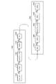
- FIG. 2 is a block diagram relating to the transmission of image data between the vehicle lighting tool 100 and the vehicle side controller 400.
- the vehicle lighting equipment 100 includes an encoder 110, a scrambler 120, a serializer 130, and a transmitter 140 in addition to the sensor 102.
- the functions of the encoder 110, the scrambler 120, the serializer 130, and the transmitter 140 can be implemented in an FPGA (Field Programmable Gate Array) or an ASIC (Application Specific Integrated Circuit).
- Encoder 110 the image data S 1 by the sensor 102 generates, into a plurality of frame data are encoded.
- the "frame data" is a frame of serial data transmission, it is noted that independent of the 1-frame image data S 1.
- the encoder 110, the image data S 1, delimited word data WD for each 8-bit is coded by 8b10b encoded word data WD. Instead of 8b10b, another coding method may be adopted.
- a predetermined number of word data are collected as frame data (payload) FD1.
- the scrambler 120 scrambles the encoded frame data FD1 using a reproducible pseudo-random signal.
- the serializer 130 converts the output FD2 of the scrambler 120 into serial data SD1.
- the transmitter 140 transmits the serial data SD1 to the vehicle side controller 400 via the cable 302.
- the vehicle-side controller 400 includes a receiver 410, a deserializer 420, a descrambler 430, a decoder 440, and a CPU (Central Processing Unit) 450.
- the receiver 410 receives the serial data SD2 from the vehicle lamp 100 via the cable 302.
- the deserializer 420 converts the serial data SD2 received by the receiver 410 into parallel frame data FD3.
- the descrambler 430 descrambles the parallel frame data FD3 using a reproducible pseudo-random signal.
- the pseudo-random signal used for descramble is the same as the pseudo-random signal used for scrambling it.
- the decoder 440 decodes the frame data FD4 after descramble by the descrambler 430, and extracts a plurality of word data WDs included in the frame data FD4.
- the decoding process in the decoder 440 is the reverse process of the coding process in the encoder 110, and after dividing every 10 bits, 8b10b decoding is performed and 8-bit word data WD is taken out.
- the original image data is restored by multiple word data WDs.
- the CPU 450 Based on the image data, the CPU 450 performs object detection processing, object identification processing, and the like to generate information necessary for automatic operation and lamp light distribution control.
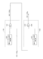
- FIG. 3 is a block diagram of the scrambler 120 and the descrambler 430.
- the scrambler 120 includes a first pseudo-random signal generator 122 and a first XOR gate 124.
- the first pseudo-random signal generator 122 generates a pseudo-random signal PRBS1.
- the configuration of the first pseudo-random signal generator 122 is not limited, and a known technique may be used.
- the first XOR gate 124 generates the exclusive logic of the pseudo-random signal PRBS1 and the frame data FD1.
- the descrambler 430 includes a second pseudo-random signal generator 432 and a second XOR gate 434.
- the second pseudo-random signal generator 432 generates the pseudo-random signal PRBS2.
- the pseudo-random signal PRBS2 is consistent with the pseudo-random signal PRBS1 used in the scrambler 120.
- the first pseudo-random signal generator 122 and the second pseudo-random signal generator 432 have the same configuration, are reset at the beginning of the frame data, and are given a common seed (initial value).
- the seeds of the first pseudo-random signal generator 122 and the second pseudo-random signal generator 432 may be changed for each frame.
- the periodicity of the serial data transmitted through the cable 302 can be further disturbed.
- the first pseudo-random signal generator 122 determines the seed of the pseudo-random signal PRBS1 to be used for scrambling the current frame data based on a part of the image data, for example, a part of the previous frame data. May be good.
- the second pseudo-random signal generator 432 also determines the seed of the pseudo-random signal PRBS2 to be used for descramble of the current frame data based on the corresponding part of the previously descrambled frame data. May be good.
- FIG. 4 is a diagram showing the structure of the frame 500 including the frame data FD.
- the frame 500 includes a preamble 502 indicating that it is the beginning of the frame 500 (SOF: Start Of Frame), a post amble 504 indicating that it is the end of the frame 500 (EOF: End Of Frame), and frame data contained therein. Includes FD. Only the frame data FD is scrambled, and the preamble 502 and the post amble 504 are added to the scrambled frame data FD'.
- FIG. 5A is a diagram showing a spectrum of radiation noise in a conventional automobile
- FIG. 5B is a diagram showing a spectrum of radiation noise in the automobile 300 according to the embodiment.
- the peak spectrum can be diffused by scrambling the serial data transmitted between the vehicle lamp 100 and the vehicle side controller 400 based on a pseudo-random signal.
- noise countermeasures can be simplified. For example, even if an inexpensive cable without a shield is adopted, the EMI specifications can be met.
- the seed used in the scrambler 120 may be included in the preamble 502 and transmitted, and the descrambler 430 may extract the seed from the preamble 502 and descramble the payload (frame data) following the preamble 502.
- the seed used for scrambling a certain frame data may be generated based on the frame data itself. For example, a bit included in a predetermined position of the frame data may be used as a seed, or a pixel value may be randomly selected from the frame data.
- the seed itself may be generated by a pseudo-random number generator different from the first pseudo-random signal generator 122.
- the present invention relates to a communication system in an automobile.
Landscapes
- Engineering & Computer Science (AREA)
- Signal Processing (AREA)
- Physics & Mathematics (AREA)
- Computer Networks & Wireless Communication (AREA)
- Spectroscopy & Molecular Physics (AREA)
- Power Engineering (AREA)
- General Physics & Mathematics (AREA)
- Multimedia (AREA)
- Dc Digital Transmission (AREA)
- Closed-Circuit Television Systems (AREA)
Abstract
自動車300は、車両用灯具100と車両側コントローラ400を備える。センサ102は、画像データを生成する。エンコーダ110は、画像データを複数のフレームデータに分割し、符号化する。スクランブラ120は、符号化後のフレームデータを、再生可能な擬似ランダム信号を用いてスクランブルする。シリアライザ130は、スクランブラ120の出力をシリアルデータに変換する。トランスミッタ140は、ケーブル302を介してシリアルデータを車両側コントローラ400に送信する。
Description
本発明は、自動車における通信システムに関する。
自動運転やヘッドランプの配光の自動制御のために、車両の周囲に存在する物体の位置および種類をセンシングする物体識別システムが利用される。物体識別システムは、センサと、センサの出力を解析する演算処理装置を含む。センサは、カメラ、LiDAR(Light Detection and Ranging、Laser Imaging Detection and Ranging)、ミリ波レーダ、超音波ソナーなどの中から、用途、要求精度やコストを考慮して選択される。
このようなセンサによって取得した画像データを、車両内で伝送する際に、ケーブルからノイズが放射される。特に、変化が少ない、あるいは同一の画像データが繰り返し伝送されると、ケーブルを伝送するシリアルデータに周期性が表れ、特定のスペクトルにノイズが集中するという問題がある。
従来の車両内の基板間通信には、ケーブルからのノイズ放射を防止するために、シールド付きのケーブルを採用する必要があり、コストが高くなるという問題があった。
本発明はこうした状況においてなされたものであり、そのある態様の例示的な目的のひとつは、ノイズ対策のコストを下げることが可能な自動車および車両用灯具の提供にある。
本発明の一態様は、灯具システムあるいは自動車に関する。システム/自動車は、車両用灯具と、車両用灯具が取得した画像データを、ケーブルを介して受信する車両側コントローラと、を備える。車両用灯具は、画像データを生成するセンサと、画像データを複数のフレームデータに分割し、符号化するエンコーダと、符号化後のフレームデータを、再生可能な擬似ランダム信号を用いてスクランブルするスクランブラと、スクランブラの出力をシリアルデータに変換するシリアライザと、ケーブルを介してシリアルデータを車両側コントローラに送信するトランスミッタと、を含む。車両側コントローラは、車両用灯具からケーブルを介してシリアルデータを受信するレシーバと、レシーバが受信したシリアルデータを、パラレルのフレームデータに変換するデシリアライザと、デシリアライザの出力を再生可能な擬似ランダム信号を用いてデスクランブルするデスクランブラと、を含む。
なお、以上の構成要素の任意の組合せ、本発明の表現を方法、装置、システム等の間で変換したものもまた、本発明の態様として有効である。
本発明のある態様によれば、ノイズ対策のコストを下げることができる。
(実施の形態の概要)
一実施の形態に係る自動車は、車両用灯具と、車両用灯具が取得した画像データを、ケーブルを介して受信する車両側コントローラと、を備える。車両用灯具は、画像データを生成するセンサと、画像データを複数のフレームデータに分割し、符号化するエンコーダと、符号化後のフレームデータを、再生可能な擬似ランダム信号を用いてスクランブルするスクランブラと、スクランブラの出力をシリアルデータに変換するシリアライザと、ケーブルを介してシリアルデータを車両側コントローラに送信するトランスミッタと、を含む。車両側コントローラは、車両用灯具からケーブルを介してシリアルデータを受信するレシーバと、レシーバが受信したシリアルデータを、パラレルのフレームデータに変換するデシリアライザと、デシリアライザの出力を再生可能な擬似ランダム信号を用いてデスクランブルするデスクランブラと、を含む。
一実施の形態に係る自動車は、車両用灯具と、車両用灯具が取得した画像データを、ケーブルを介して受信する車両側コントローラと、を備える。車両用灯具は、画像データを生成するセンサと、画像データを複数のフレームデータに分割し、符号化するエンコーダと、符号化後のフレームデータを、再生可能な擬似ランダム信号を用いてスクランブルするスクランブラと、スクランブラの出力をシリアルデータに変換するシリアライザと、ケーブルを介してシリアルデータを車両側コントローラに送信するトランスミッタと、を含む。車両側コントローラは、車両用灯具からケーブルを介してシリアルデータを受信するレシーバと、レシーバが受信したシリアルデータを、パラレルのフレームデータに変換するデシリアライザと、デシリアライザの出力を再生可能な擬似ランダム信号を用いてデスクランブルするデスクランブラと、を含む。
この態様によると、元の画像データが単調な場合でも、擬似ランダム信号によってスクランブルすることにより、単調性を乱し、スペクトルを拡散することができる。これによりノイズ対策のコストを下げることができる。
スクランブラは、擬似ランダム信号を生成する第1擬似ランダム信号発生器と、擬似ランダム信号とフレームデータの排他的論理を生成する第1XORゲートと、を含んでもよい。デスクランブラは、擬似ランダム信号を生成する第2擬似ランダム信号発生器と、擬似ランダム信号とフレームデータの排他的論理を生成する第2XORゲートと、を含んでもよい。
第1擬似ランダム信号発生器は、画像データの一部にもとづいて、擬似ランダム信号の生成のシード(初期値)を決定してもよい。
第1擬似ランダム信号発生器は、1フレームごとに、擬似ランダム信号のシードを変化させてもよい。
本発明の別の態様は、車両用灯具である。この車両用灯具は、ランプと、画像データを生成するセンサと、画像データを複数のフレームデータに分割し、符号化するエンコーダと、エンコーダの出力データを再生可能な擬似ランダム信号を用いてスクランブルするスクランブラと、スクランブラの出力をシリアルデータに変換するシリアライザと、ケーブルを介してスクランブル後のシリアルデータを車両側コントローラに送信するトランスミッタと、を備える。
以下、本発明を好適な実施の形態をもとに図面を参照しながら説明する。実施の形態は、発明を限定するものではなく例示であって、実施の形態に記述されるすべての特徴やその組み合わせは、必ずしも発明の本質的なものであるとは限らない。各図面に示される同一または同等の構成要素、部材、処理には、同一の符号を付するものとし、適宜重複した説明は省略する。
図1は、実施の形態に係る自動車300を示す図である。自動車300は、車両用灯具100L,100Rと、車両側コントローラ(ECU:Electronic Control Unit)400を備える。車両用灯具100L,100Rには、ハイビーム104やロービーム106を構成する光源、それらの点灯回路、ヒートシンクなどが内蔵される。また車両用灯具100L,100Rの少なくとも一方(この例では両方)は、センサ102を備える。センサ102は、可視光カメラや赤外線カメラ、TOFカメラなどであり、画像データを生成する。左右の車両用灯具100L,100Rでセンサの種類が異なっていてもよい。車両用灯具100は、センサ102が生成した画像データを、ケーブル302を介して車両側コントローラ400に送信する。
なお車両用灯具100と車両側コントローラ400は、ケーブル302とは別に、CAN(Controller Area Network)やLIN(Local Interconnect Network)などのインタフェースを介して接続されており、画像データ以外のデータ、制御信号を送受信可能となっている。
車両側コントローラ400は、車両用灯具100から受信した画像データにもとづいて、自動運転制御を行う。あるいは画像データは、車両側コントローラ400の自動配光制御に利用してもよい。
図2は、車両用灯具100と車両側コントローラ400の間の画像データの伝送に関するブロック図である。
車両用灯具100は、センサ102に加えて、エンコーダ110、スクランブラ120、シリアライザ130、トランスミッタ140を備える。エンコーダ110、スクランブラ120、シリアライザ130、トランスミッタ140の機能は、FPGA(Field Programmable Gate Array)やASIC(Application Specific Integrated Circuit)に実装することができる。
エンコーダ110は、センサ102が生成する画像データS1を、複数のフレームデータに分割し、符号化する。この「フレームデータ」は、シリアルデータ伝送のフレームであり、画像データS1の1フレームとは無関係であることに留意されたい。たとえば、エンコーダ110は、画像データS1を、8ビットごとのワードデータWDに区切り、ワードデータWDを8b10b符号化によって符号化する。8b10bに代えて、別の符号化方式を採用してもよい。そして、所定数のワードデータを、フレームデータ(ペイロード)FD1としてまとめる。フレームデータFD1の長さは、特に限定されず、送信するデータの内容やバス規格にもとづいて決めればよい。たとえば、バス幅64ビット、バースト長が256であるとき、1フレームデータは、8×256=1024ワードを含むことができる。
スクランブラ120は、符号化後のフレームデータFD1を、再生可能な擬似ランダム信号を用いてスクランブルする。シリアライザ130は、スクランブラ120の出力FD2をシリアルデータSD1に変換する。トランスミッタ140は、ケーブル302を介してシリアルデータSD1を車両側コントローラ400に送信する。
車両側コントローラ400は、レシーバ410、デシリアライザ420、デスクランブラ430、デコーダ440、CPU(Central Processing Unit)450を含む。レシーバ410は、車両用灯具100からケーブル302を介してシリアルデータSD2を受信する。デシリアライザ420は、レシーバ410が受信したシリアルデータSD2を、パラレルのフレームデータFD3に変換する。
デスクランブラ430は、パラレルのフレームデータFD3を、再生可能な擬似ランダム信号を用いてデスクランブルする。デスクランブルに使用する擬似ランダム信号は、それをスクランブルする際に使用した擬似ランダム信号と同一である。
デコーダ440は、デスクランブラ430によるデスクランブル後のフレームデータFD4を復号し、それに含まれる複数のワードデータWDを取り出す。デコーダ440における復号処理は、エンコーダ110における符号化処理の逆処理であり、10ビットごとに区切った後に、8b10b復号を行い、8ビットのワードデータWDを取り出す。
複数のワードデータWDによって、元の画像データが復元される。CPU450は、画像データにもとづいて、物体検出処理や、物体識別処理などを行い、自動運転やランプの配光制御に必要な情報を生成する。
図3は、スクランブラ120およびデスクランブラ430のブロック図である。スクランブラ120は、第1擬似ランダム信号発生器122、第1XORゲート124を含む。第1擬似ランダム信号発生器122は、擬似ランダム信号PRBS1を生成する。第1擬似ランダム信号発生器122の構成は限定されず、公知技術を用いればよい。第1XORゲート124は、擬似ランダム信号PRBS1とフレームデータFD1の排他的論理を生成する。
デスクランブラ430は、第2擬似ランダム信号発生器432、第2XORゲート434を含む。第2擬似ランダム信号発生器432は、擬似ランダム信号PRBS2を生成する。擬似ランダム信号PRBS2は、スクランブラ120において使用された擬似ランダム信号PRBS1と一致している。第1擬似ランダム信号発生器122と第2擬似ランダム信号発生器432は同一の構成を有し、フレームデータの先頭においてリセットされ、共通のシード(初期値)が与えられる。
好ましくは、第1擬似ランダム信号発生器122、第2擬似ランダム信号発生器432のシードは、フレーム毎ごとに変化させるとよい。これにより、ケーブル302を伝送するシリアルデータの周期性をさらに乱すことができる。
第1擬似ランダム信号発生器122は、画像データの一部、たとえば、1個前のフレームデータの一部にもとづいて、現在のフレームデータのスクランブルに使用する擬似ランダム信号PRBS1のシードを決定してもよい。第2擬似ランダム信号発生器432も同様に、1個前にデスクランブルしたフレームデータの対応する一部にもとづいて、現在のフレームデータのデスクランブルに使用する擬似ランダム信号PRBS2のシードを決定してもよい。
図4は、フレームデータFDを含むフレーム500の構造を示す図である。フレーム500は、フレーム500の先頭(SOF:Start Of Frame)であることを示すプリアンブル502、フレーム500の終端(EOF:End Of Frame)であることを示すポストアンブル504と、それらに含まれるフレームデータFDを含む。フレームデータFDのみがスクランブルされ、スクランブル後のフレームデータFD’に、プリアンブル502およびポストアンブル504が付加される。
以上が車両用灯具100の構成である。続いてその動作を説明する。図5(a)は、従来の自動車における放射ノイズのスペクトルを、図5(b)は実施の形態に係る自動車300における放射ノイズのスペクトルを示す図である。
図5(a)を参照する。スクランブルを行わない場合、スクランブルを行わないと、変化が少ないあるいは同一の画像データが繰り返し伝送されると、ケーブル302を伝送するシリアルデータに周期性が表れ、特定のスペクトルf0にノイズが集中する。したがって車載機器に要求されるEMI(Electromagnetic Interference)の仕様を満たすためには、シールドで被覆されたケーブルを採用するなどの対策が必要となる。
図5(a)を参照する。実施の形態に係る自動車300では、車両用灯具100と車両側コントローラ400の間を伝送するシリアルデータに、擬似ランダム信号にもとづくスクランブルをかけることにより、ピークスペクトルを拡散することができる。これにより、ノイズ対策を簡素化できる。たとえば、シールド無しの安価なケーブルを採用しても、EMIの仕様を満たすことができるようになる。
以上、本発明について、実施の形態をもとに説明した。この実施の形態は例示であり、それらの各構成要素や各処理プロセスの組み合わせにいろいろな変形例が可能なこと、またそうした変形例も本発明の範囲にあることは当業者に理解されるところである。以下、こうした変形例について説明する。
スクランブラ120において使用したシードを、プリアンブル502に含めて送信し、デスクランブラ430は、プリアンブル502からシードを抽出し、プリアンブル502に続くペイロード(フレームデータ)をデスクランブルしてもよい。
この場合において、あるフレームデータ(ペイロード)のスクランブルに使用するシードを、そのフレームデータ自身にもとづいて生成してもよい。たとえばフレームデータの所定の位置に含まれるビットをシードとして用いてもよいし、フレームデータの中からランダムにピクセル値を選択してもよい。
あるいはシード自体を、第1擬似ランダム信号発生器122とは別の擬似乱数発生器によって生成してもよい。
実施の形態にもとづき、具体的な語句を用いて本発明を説明したが、実施の形態は、本発明の原理、応用の一側面を示しているにすぎず、実施の形態には、請求の範囲に規定された本発明の思想を逸脱しない範囲において、多くの変形例や配置の変更が認められる。
本発明は、自動車における通信システムに関する。
100 車両用灯具
102 センサ
110 エンコーダ
120 スクランブラ
122 第1擬似ランダム信号発生器
124 第1XORゲート
130 シリアライザ
140 トランスミッタ
300 自動車
302 ケーブル
400 車両側コントローラ
410 レシーバ
420 デシリアライザ
430 デスクランブラ
432 第2擬似ランダム信号発生器
434 第2XORゲート
440 デコーダ
450 CPU
102 センサ
110 エンコーダ
120 スクランブラ
122 第1擬似ランダム信号発生器
124 第1XORゲート
130 シリアライザ
140 トランスミッタ
300 自動車
302 ケーブル
400 車両側コントローラ
410 レシーバ
420 デシリアライザ
430 デスクランブラ
432 第2擬似ランダム信号発生器
434 第2XORゲート
440 デコーダ
450 CPU
Claims (5)
- 車両用灯具と、
前記車両用灯具が取得した画像データを、ケーブルを介して受信する車両側コントローラと、
を備え、
前記車両用灯具は、
画像データを生成するセンサと、
前記画像データを複数のフレームデータに分割し、符号化するエンコーダと、
符号化後の前記フレームデータを、再生可能な擬似ランダム信号を用いてスクランブルするスクランブラと、
前記スクランブラの出力をシリアルデータに変換するシリアライザと、
前記ケーブルを介して前記シリアルデータを前記車両側コントローラに送信するトランスミッタと、
を含み、
前記車両側コントローラは、
前記車両用灯具から前記ケーブルを介して前記シリアルデータを受信するレシーバと、
前記レシーバが受信した前記シリアルデータをパラレルのフレームデータに変換するデシリアライザと、
前記デシリアライザの出力を、再生可能な擬似ランダム信号を用いてデスクランブルするデスクランブラと、
を含むことを特徴とする自動車。 - 前記スクランブラは、
前記擬似ランダム信号を生成する第1擬似ランダム信号発生器と、
前記擬似ランダム信号と前記フレームデータの排他的論理を生成する第1XORゲートと、
を含み、
前記デスクランブラは、
前記擬似ランダム信号を生成する第2擬似ランダム信号発生器と、
前記擬似ランダム信号と前記フレームデータの排他的論理を生成する第2XORゲートと、
を含むことを特徴とする請求項1に記載の自動車。 - 前記第1擬似ランダム信号発生器は、前記画像データの一部にもとづいて、前記擬似ランダム信号の生成のシードを決定することを特徴とする請求項2に記載の自動車。
- 前記第1擬似ランダム信号発生器は、1フレームごとに、前記擬似ランダム信号のシードを変化させることを特徴とする請求項2または3に記載の自動車。
- ランプと、
画像データを生成するセンサと、
前記画像データを複数のフレームデータに分割し、符号化するエンコーダと、
符号化後の前記フレームデータを、再生可能な擬似ランダム信号を用いてスクランブルするスクランブラと、
前記スクランブラの出力をシリアルデータに変換するシリアライザと、
ケーブルを介してスクランブル後のシリアルデータを車両側コントローラに送信するトランスミッタと、
を備えることを特徴とする車両用灯具。
Priority Applications (3)
| Application Number | Priority Date | Filing Date | Title |
|---|---|---|---|
| JP2021508893A JPWO2020195608A1 (ja) | 2019-03-26 | 2020-03-03 | |
| CN202080023844.1A CN113632412A (zh) | 2019-03-26 | 2020-03-03 | 汽车及车辆用灯具 |
| US17/484,673 US20220191072A1 (en) | 2019-03-26 | 2020-03-03 | Automobile |
Applications Claiming Priority (2)
| Application Number | Priority Date | Filing Date | Title |
|---|---|---|---|
| JP2019058307 | 2019-03-26 | ||
| JP2019-058307 | 2019-03-26 |
Publications (1)
| Publication Number | Publication Date |
|---|---|
| WO2020195608A1 true WO2020195608A1 (ja) | 2020-10-01 |
Family
ID=72610025
Family Applications (1)
| Application Number | Title | Priority Date | Filing Date |
|---|---|---|---|
| PCT/JP2020/008926 Ceased WO2020195608A1 (ja) | 2019-03-26 | 2020-03-03 | 自動車および車両用灯具 |
Country Status (4)
| Country | Link |
|---|---|
| US (1) | US20220191072A1 (ja) |
| JP (1) | JPWO2020195608A1 (ja) |
| CN (1) | CN113632412A (ja) |
| WO (1) | WO2020195608A1 (ja) |
Cited By (1)
| Publication number | Priority date | Publication date | Assignee | Title |
|---|---|---|---|---|
| JP2023101308A (ja) * | 2022-01-07 | 2023-07-20 | Mmiセミコンダクター株式会社 | ポンプの構造体 |
Citations (4)
| Publication number | Priority date | Publication date | Assignee | Title |
|---|---|---|---|---|
| JP2013164913A (ja) * | 2012-02-09 | 2013-08-22 | Koito Mfg Co Ltd | 車両用灯具 |
| WO2014061334A1 (ja) * | 2012-10-17 | 2014-04-24 | 株式会社ソニー・コンピュータエンタテインメント | 情報処理装置 |
| JP2014168152A (ja) * | 2013-02-28 | 2014-09-11 | Mitsubishi Electric Corp | 信号送信装置、信号受信装置及び信号伝送システム |
| JP2018148275A (ja) * | 2017-03-01 | 2018-09-20 | 株式会社メガチップス | 画像伝送システムの受信装置及び受信装置の作動方法 |
Family Cites Families (18)
| Publication number | Priority date | Publication date | Assignee | Title |
|---|---|---|---|---|
| US5561714A (en) * | 1994-12-12 | 1996-10-01 | Tektronix, Inc. | Scrambling system for serial digital video |
| US5710815A (en) * | 1995-06-07 | 1998-01-20 | Vtech Communications, Ltd. | Encoder apparatus and decoder apparatus for a television signal having embedded viewer access control data |
| FR2826727B1 (fr) * | 2001-06-29 | 2004-05-28 | Valeo Vision | Procede et dispositif pour detecter l'etat d'humidite d'une route sur laquelle circule un vehicule |
| US7672285B2 (en) * | 2004-06-28 | 2010-03-02 | Dtvg Licensing, Inc. | Method and apparatus for minimizing co-channel interference by scrambling |
| US7688231B2 (en) * | 2005-08-29 | 2010-03-30 | Mrv Communications, Inc. | Transmission of pathological data patterns |
| US20090103727A1 (en) * | 2007-10-17 | 2009-04-23 | Heywood Gareth M | Sync-bit Insertion for Timing Reference Signals to Prevent Long Runs of Static Data in Serial Digital Interfaces |
| CN101599811B (zh) * | 2008-06-02 | 2011-04-06 | 华为技术有限公司 | 一种数据处理装置,通信设备以及数据处理方法 |
| CN107181581B (zh) * | 2012-01-19 | 2021-06-01 | 太阳专利信托公司 | 用户设备和接收方法 |
| US20140247349A1 (en) * | 2013-03-04 | 2014-09-04 | GM Global Technology Operations LLC | Integrated lighting, camera and sensor unit |
| CN103873873B (zh) * | 2014-03-24 | 2018-02-13 | 上海航天电子通讯设备研究所 | 一种非可靠信道下的图像编解码方法 |
| US9444655B2 (en) * | 2014-03-25 | 2016-09-13 | Intel IP Corporation | Apparatus, method and system of scrambling a wireless transmission |
| KR102268106B1 (ko) * | 2014-11-17 | 2021-06-22 | 엘지이노텍 주식회사 | 무선 수신 장치, 이를 포함하는 차량용 후방 감지 장치 및 방법 |
| US9784839B2 (en) * | 2014-11-26 | 2017-10-10 | Magna Electronics Solutions Gmbh | Automotive lighting device and a vehicle having the same |
| JP6923310B2 (ja) * | 2016-11-29 | 2021-08-18 | 株式会社小糸製作所 | 車両用ランプの点灯制御装置 |
| CN108347281B (zh) * | 2017-01-23 | 2020-12-25 | 中国移动通信有限公司研究院 | 一种车辆通信方法、车辆通信装置和车辆 |
| CN108631924B (zh) * | 2017-03-24 | 2020-04-21 | 华为技术有限公司 | 一种资源映射方法及其装置 |
| US20190349609A1 (en) * | 2018-05-09 | 2019-11-14 | Pesa Switching Systems, Inc. | System and method of controlling access to audio and video feeds in a closed network |
| US10742237B2 (en) * | 2018-06-21 | 2020-08-11 | Western Digital Technologies, Inc. | Memory device with adaptive descrambling |
-
2020
- 2020-03-03 WO PCT/JP2020/008926 patent/WO2020195608A1/ja not_active Ceased
- 2020-03-03 JP JP2021508893A patent/JPWO2020195608A1/ja active Pending
- 2020-03-03 CN CN202080023844.1A patent/CN113632412A/zh active Pending
- 2020-03-03 US US17/484,673 patent/US20220191072A1/en not_active Abandoned
Patent Citations (4)
| Publication number | Priority date | Publication date | Assignee | Title |
|---|---|---|---|---|
| JP2013164913A (ja) * | 2012-02-09 | 2013-08-22 | Koito Mfg Co Ltd | 車両用灯具 |
| WO2014061334A1 (ja) * | 2012-10-17 | 2014-04-24 | 株式会社ソニー・コンピュータエンタテインメント | 情報処理装置 |
| JP2014168152A (ja) * | 2013-02-28 | 2014-09-11 | Mitsubishi Electric Corp | 信号送信装置、信号受信装置及び信号伝送システム |
| JP2018148275A (ja) * | 2017-03-01 | 2018-09-20 | 株式会社メガチップス | 画像伝送システムの受信装置及び受信装置の作動方法 |
Cited By (1)
| Publication number | Priority date | Publication date | Assignee | Title |
|---|---|---|---|---|
| JP2023101308A (ja) * | 2022-01-07 | 2023-07-20 | Mmiセミコンダクター株式会社 | ポンプの構造体 |
Also Published As
| Publication number | Publication date |
|---|---|
| JPWO2020195608A1 (ja) | 2020-10-01 |
| CN113632412A (zh) | 2021-11-09 |
| US20220191072A1 (en) | 2022-06-16 |
Similar Documents
| Publication | Publication Date | Title |
|---|---|---|
| US20120069184A1 (en) | Rear view device for a motor vehicle | |
| WO2020045123A1 (ja) | 受光素子および測距システム | |
| KR101685012B1 (ko) | 가시광 무선통신을 이용하는 차량간의 통신 장치 및 그 방법 | |
| WO2017130996A1 (ja) | 距離測定装置 | |
| JP2021001763A (ja) | 測距装置、測距方法、および、測距システム | |
| CN110168403A (zh) | 距离测量装置、距离测量方法和距离测量系统 | |
| US11743449B2 (en) | Imaging device and electronic apparatus | |
| KR20210015744A (ko) | 고체 촬상 소자, 촬상 장치, 및 고체 촬상 소자의 제어 방법 | |
| WO2020195608A1 (ja) | 自動車および車両用灯具 | |
| WO2020045124A1 (ja) | 受光素子および測距システム | |
| CN1291550C (zh) | 光电接近度开关 | |
| WO2021039458A1 (ja) | 測距センサおよびその駆動方法、並びに、測距モジュール | |
| DE102013002671A1 (de) | Erfassung einer Entfernungsinformation für ein Fahrzeug | |
| DE102017215614A1 (de) | Stochastisch getaktete Bilderzeugung eines Lidar-System | |
| WO2020166349A1 (ja) | 受光装置、ヒストグラム生成方法、および測距システム | |
| US11245829B2 (en) | Communication device of a motor vehicle, a motor vehicle lighting device for the communication device of a motor vehicle and a Car2Car or Car2X communication method for a motor vehicle | |
| WO2005008970A3 (fr) | Procede et dispositif de transmission de donnees | |
| CA2106744C (en) | Multiple-master digital communication technique utilizing a dedicated contention bus | |
| JP2023522667A (ja) | 画像データを管理するための方法及び車両照明システム | |
| JP2020136811A (ja) | 固体撮像装置及び撮像装置 | |
| Anitha et al. | Accident avoidance by using Li-Fi technology in automobiles | |
| US20040008624A1 (en) | Reduced peak EMI bus using variable bit rate spreading | |
| WO2021215113A1 (ja) | 固体撮像素子、センシングシステム、および、固体撮像素子の制御方法 | |
| US20060013582A1 (en) | Optical communications processing system, components and operating method thereof | |
| Bates et al. | Comparison of LED illumination patterns for camera based car to car communications |
Legal Events
| Date | Code | Title | Description |
|---|---|---|---|
| 121 | Ep: the epo has been informed by wipo that ep was designated in this application |
Ref document number: 20779554 Country of ref document: EP Kind code of ref document: A1 |
|
| ENP | Entry into the national phase |
Ref document number: 2021508893 Country of ref document: JP Kind code of ref document: A |
|
| NENP | Non-entry into the national phase |
Ref country code: DE |
|
| 122 | Ep: pct application non-entry in european phase |
Ref document number: 20779554 Country of ref document: EP Kind code of ref document: A1 |