WO2020195174A1 - 操舵特性設定装置、操舵特性設定方法、及び操舵特性設定プログラム - Google Patents
操舵特性設定装置、操舵特性設定方法、及び操舵特性設定プログラム Download PDFInfo
- Publication number
- WO2020195174A1 WO2020195174A1 PCT/JP2020/004012 JP2020004012W WO2020195174A1 WO 2020195174 A1 WO2020195174 A1 WO 2020195174A1 JP 2020004012 W JP2020004012 W JP 2020004012W WO 2020195174 A1 WO2020195174 A1 WO 2020195174A1
- Authority
- WO
- WIPO (PCT)
- Prior art keywords
- steering
- vehicle
- setting
- assist
- characteristic
- Prior art date
- Legal status (The legal status is an assumption and is not a legal conclusion. Google has not performed a legal analysis and makes no representation as to the accuracy of the status listed.)
- Ceased
Links
Images




Classifications
-
- B—PERFORMING OPERATIONS; TRANSPORTING
- B62—LAND VEHICLES FOR TRAVELLING OTHERWISE THAN ON RAILS
- B62D—MOTOR VEHICLES; TRAILERS
- B62D5/00—Power-assisted or power-driven steering
- B62D5/04—Power-assisted or power-driven steering electrical, e.g. using an electric servo-motor connected to, or forming part of, the steering gear
-
- B—PERFORMING OPERATIONS; TRANSPORTING
- B62—LAND VEHICLES FOR TRAVELLING OTHERWISE THAN ON RAILS
- B62D—MOTOR VEHICLES; TRAILERS
- B62D6/00—Arrangements for automatically controlling steering depending on driving conditions sensed and responded to, e.g. control circuits
Definitions
- the present disclosure relates to a device, a method, and a program for setting the steering characteristics of the electric power steering provided in the vehicle.
- the steering characteristics can be changed, for example, by the driver editing the steering characteristics at the timing when the mounted object is changed.
- the technique described in Patent Document 1 has room for improvement in improving the steering performance of the vehicle.
- This disclosure was devised in view of the above-mentioned problems, and one of the purposes is to improve the steering performance of the vehicle.
- the steering characteristic setting device is a steering characteristic setting device for electric power steering that gives an assist force to the steering system of the vehicle, and acquires information according to the mounted object mounted on the vehicle. It includes an acquisition unit and a setting unit that sets the characteristics of the assist force based on the information acquired by the acquisition unit.
- the information includes the height of the center of gravity of the vehicle, and the setting unit has the characteristic that the larger the height of the center of gravity, the smaller the assist force. May be set. In this case, the higher the height of the center of gravity, the more the sharp turning (sudden steering) of the vehicle is suppressed, so that the posture of the vehicle becomes more stable.
- the information includes the front axle weight of the vehicle, and the setting unit has the characteristics so that the larger the front axle weight, the larger the assist force. May be set. In this case, even if the front axle weight is large, it becomes easy to steer the vehicle.
- the steering characteristic setting device includes a storage unit that stores a plurality of maps in which the characteristics are defined, and the setting unit stores the storage unit based on the information acquired by the acquisition unit.
- One of the maps stored in the unit may be selected, and the characteristics specified in the selected map may be set. In this case, the control configuration is easily simplified.
- the vehicle may be a truck. In this case, even if the bodywork as the load is changed in the truck, the characteristics of the assist force suitable for the load can be easily set.
- the vehicle may be a bus. In this case, even if the number, arrangement, etc. of the occupants and luggage as the load are changed on the bus, the characteristics of the assist force suitable for the load can be easily set.
- the steering characteristic setting method according to the present application example is a steering characteristic setting method of electric power steering that gives an assist force to the steering system of the vehicle, and acquires information according to the mounted object mounted on the vehicle. It includes an acquisition step and a setting step for setting the characteristics of the assist force based on the information acquired in the acquisition step.
- a steering characteristic setting method of electric power steering that gives an assist force to the steering system of the vehicle, and acquires information according to the mounted object mounted on the vehicle. It includes an acquisition step and a setting step for setting the characteristics of the assist force based on the information acquired in the acquisition step.
- the information includes the height of the center of gravity of the vehicle, and in the setting step, the characteristic is such that the larger the height of the center of gravity, the smaller the assist force. May be set. In this case, the higher the height of the center of gravity, the more the sharp turning (sudden steering) of the vehicle is suppressed, so that the posture of the vehicle becomes more stable.
- the information includes the front axle weight of the vehicle, and in the setting step, the characteristic so that the larger the front axle weight, the larger the assist force. May be set. In this case, even if the front axle weight is large, it becomes easy to steer the vehicle.
- the steering characteristic setting method includes a storage step of storing a plurality of maps in which the characteristic is defined before the implementation of the setting step, and is acquired in the acquisition step in the setting step. Based on the above information, one may be selected from the maps stored in the storage process, and the characteristics specified in the selected map may be set. In this case, the control configuration is easily simplified.
- the steering characteristic setting program according to the present application example is a steering characteristic setting program of electric power steering that gives an assist force to the steering system of the vehicle, and acquires information according to the mounted object mounted on the vehicle.
- the computer is made to execute the acquisition step and the setting step of setting the characteristics of the assist force based on the information acquired in the acquisition step.
- the steering performance of the vehicle can be improved.
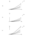
- FIG. (A) to (c) are all map examples stored in the storage unit of the steering characteristic setting device of FIG. This is a map example for selecting one from the maps stored in the storage unit.
- FIG. (A) to (c) is a map example for selecting one from the maps stored in the storage unit.
- the steering characteristic setting device the steering characteristic setting method, and the steering characteristic setting program (hereinafter, simply referred to as "setting device”, “setting method”, and “setting program") will be described with reference to the drawings.
- the embodiments shown below are merely examples, and there is no intention of excluding the application of various modifications and techniques not specified in the following embodiments.
- Each configuration of the following embodiments can be variously modified and implemented without departing from the gist thereof.
- it can be selected as needed, or can be combined as appropriate.
- the setting device, the setting method, and the setting program according to the present embodiment set the steering characteristics of the electric power steering 2 provided in the vehicle 1 shown in FIG.
- the vehicle 1 is a truck having a loading platform (pedestal portion) 11 is illustrated.
- the vehicle 1 is an electric vehicle that travels by driving a traveling motor with the electric power of a battery (not shown).
- the vehicle 1 can mount various loads (bodywork) 3 on the loading platform 11, and depending on the type of loader 3 to be mounted (bodywork), for example, a crane truck, a dump truck, a tank truck, a mixer truck, etc. Used as a wrecker truck, packer truck, van, etc.
- the shape, size, weight, etc. of the load 3 differ depending on the type of the load 3.
- the vehicle 1 is mechanically connected to a steering wheel 21 operated by a driver, a steering mechanism 22 that changes the steering angle of the front wheels 16 according to the steering angle of the steering wheel 21, and a steering wheel 21 and a steering mechanism 22.
- a steering shaft 23 and a column 24 that rotatably supports the steering shaft 23 are provided. These devices 21 to 24 constitute the steering system of the vehicle 1.
- the electric power steering (EPS) 2 is a device that gives an assist force to the steering system of the vehicle 1.
- the electric power steering 2 of the present embodiment includes an electric steering motor 2A that generates an assist torque Ta as an assist force, and a steering ECU 2B (see FIG. 2) that controls the operation of the steering motor 2A.
- the electric power steering 2 in which the steering motor 2A is a rack assist type or a pinion assist type provided in the steering mechanism 22 is illustrated.
- a column assist type electric power steering in which the steering motor 2A is provided in the column 24 may be applied. Further, although FIG.
- FIG. 1 illustrates a structure in which the steering mechanism 22 is connected to the lower end portion of the steering shaft 23, the structure of the steering system is not limited to this, and for example, between the steering shaft 23 and the steering mechanism 22
- An intermediate shaft (not shown) connected to the lower end of the steering shaft 23 via a bevel gear (bevel gear) may be provided.
- the vehicle 1 is provided with a VCU (Vehicle Control Unit) 4 for controlling the traveling motor and a setting ECU 5 as the setting device described above.
- VCU Vehicle Control Unit
- Each of these ECUs 2B, 4 and 5 is an electronic control device (computer) configured as an LSI device or an embedded electronic device in which a microprocessor, ROM, RAM, etc. are integrated, and is connected to a communication line of an in-vehicle network. Has been done.
- the setting ECU 5 of this embodiment can communicate with both the steering ECU 2B and the VCU 4.
- the vehicle 1 is provided with various sensors 12 to 15.
- the height sensor 12 is attached to, for example, the vehicle body frame (not shown) of the vehicle 1, and is located on the front side of the vehicle 1 based on the distance (relative position) between the front axle (not shown) supporting the front wheels 16 and the vehicle body frame. Detects vehicle height Hf.
- the acceleration sensor 13 detects the acceleration of the vehicle 1 in the front-rear direction. Specifically, the acceleration sensor 13 detects the acceleration ⁇ in the forward direction while the vehicle 1 is accelerating, and detects the acceleration (deceleration) ⁇ B in the rear direction while the vehicle 1 is decelerating.
- acceleration ⁇ in the forward direction is simply referred to as “acceleration ⁇ ”
- acceleration ⁇ B in the rear direction is referred to as “deceleration ⁇ B ”.
- the height sensor 12 and the acceleration sensor 13 transmit the detected information to the setting ECU 5.
- the speed sensor 14 detects the traveling speed V of the vehicle 1.
- the steering torque sensor 15 detects the steering torque Ts input from the driver to the steering wheels 21.
- the speed sensor 14 and the steering torque sensor 15 transmit the detected information to the steering ECU 2B.
- the setting control is a control for setting the steering characteristics of the electric power steering 2.
- the steering characteristic referred to here is the characteristic of the assist torque Ta described above, and is defined as, for example, the property of the assist torque Ta with respect to the steering torque Ts and the traveling speed V.
- the steering characteristics are also referred to as "assist characteristics”.
- the load 3 changes according to the application and usage conditions, even if the base vehicle body structure (structure other than the load 3) is the same, if the load 3 is different, the optimum assist characteristics are also different. there is a possibility.
- the assist characteristic that exerts a larger assist torque Ta is preferable as compared with the case where the weight of the load 3 is relatively small.
- the height Hc of the center of gravity of the vehicle 1 also changes according to the load 3.
- the optimum assist characteristics change. For example, when the height Hc of the center of gravity is relatively high, the posture of the vehicle 1 is less stable than when the height Hc of the center of gravity is relatively low, so that sudden steering (sudden turning of the vehicle 1) is suppressed.
- an assist characteristic that exerts a smaller assist torque Ta is preferable.
- the assist characteristic is set based on the parameter that changes according to the load 3.
- the height Hc of the center of gravity and the weight of the front axle (load applied to the front axle of the vehicle 1) Wf are exemplified as the above-mentioned parameters.
- the height of the center of gravity Hc and the weight of the front axle Wf are both values that change according to the load 3.
- the setting ECU 5 includes a storage unit 5A, an acquisition unit 5B, and a setting unit 5C as elements for executing setting control.
- a storage unit 5A for executing setting control.
- all of these elements 5A, 5B, and 5C are realized by software.
- these elements 5A, 5B, and 5C may be realized by hardware (electronic circuit), or may be realized by using software and hardware in combination.
- the storage unit 5A, the acquisition unit 5B, and the setting unit 5C are provided as the functions of the computer program (setting program) 7. Therefore, the setting ECU 5 executes the setting control by executing the computer program 7.
- the computer program 7 may be provided so that it can be executed by the setting ECU 5, and is stored in a storage device such as an HDD (Hard Disk Drive) or SSD (Solid State Drive) in the setting ECU 5, for example. It may be recorded in a medium that can be read by the setting ECU 5 or in an online storage on a network to which the setting ECU 5 can be connected.
- the storage unit 5A stores a plurality of maps in which assist characteristics are defined.
- each of these maps will be referred to as an "assist map".
- the assist characteristics defined in the plurality of assist maps are different from each other.
- each assist map of the present embodiment defines the steering torque Ts and the assist torque Ta with respect to the traveling speed V.
- the vertical axis is the assist torque Ta and the horizontal axis is the steering torque Ts, and the lines showing the relationship between the assist torque Ta and the steering torque Ts are for each of the plurality of traveling speeds V.
- the assist torque Ta is defined to increase as the steering torque Ts increases and as the traveling speed V increases.
- three assist maps A1, A2, and B1 are illustrated in FIGS. 3A to 3C, nine assist maps (A1 to A3, B1 to B1 to be described later) are shown in the storage unit 5A of the present embodiment. B3, C1 to C3) are stored. These assist maps are created based on the results of tests and simulations carried out in advance so that the steering performance of the vehicle 1 is ensured.
- the acquisition unit 5B acquires a parameter (information according to the load 3) that changes according to the load 3.
- the height Hc of the center of gravity of the vehicle 1 and the weight Wf of the front axle are acquired as parameters.
- the acquisition unit 5B uses the respective values Hf, ⁇ , ⁇ B detected by the height sensor 12 and the acceleration sensor 13 while the vehicle 1 is traveling, and the motor current value I transmitted from the VCU 4.
- the height Hc of the center of gravity and the weight Wf of the front axle are calculated.
- the center-of-gravity height Hc is calculated by the following equation (1) when the vehicle 1 is decelerating (when the acceleration sensor 13 detects the deceleration ⁇ B ).
- Hc ⁇ W ⁇ L / ( ⁇ B ⁇ W) ⁇ ⁇ ⁇ (1)
- ⁇ W in the equation (1) is the amount of load (load movement amount) that moves from the rear to the front of the vehicle 1 when the vehicle 1 is decelerated.
- the load transfer amount ⁇ W is calculated based on, for example, the amount of change in the vehicle height Hf detected by the height sensor 12.
- the load transfer amount ⁇ W may be calculated based on the information detected by the 3-axis acceleration sensor.
- L in the formula (1) is the wheelbase (distance between the front axle and the rear axle) of the vehicle 1. Since the wheelbase L is a value unique to the vehicle 1, for example, it is measured or set when the production of the vehicle 1 is completed, and is stored (stored) in the setting ECU 5.
- T in the formula (2) is the drive torque of the traveling motor, and is calculated based on the motor current value I transmitted from the VCU 4.
- the motor current value I may be a control value instructed by the VCU 4 to the traveling motor, or may be a detection value detected by a sensor provided in the electric circuit of the traveling motor.
- R in the formula (2) is the radius of the tire of the vehicle 1 (tire radius). The tire radius r is, for example, measured or set when the production of the vehicle 1 is completed, and is stored (stored) in the setting ECU 5.
- the acquisition unit 5B first calculates a drive torque T based on the motor current value I transmitted from the VCU 4, the drive torque T, the acceleration ⁇ detected by the acceleration sensor 13, and the tire radius r stored in advance. By applying and to the equation (2), the vehicle weight W is calculated. Further, the acquisition unit 5B calculates the load transfer amount ⁇ W based on the vehicle height Hf detected by the height sensor 12, and detects the load transfer amount ⁇ W, the wheelbase L stored in advance, and the acceleration sensor 13. The height of the center of gravity Hc is calculated by applying the deceleration ⁇ B and the vehicle weight W calculated from the equation (2) to the equation (1).
- the front axle weight Wf is calculated based on, for example, the vehicle height Hf detected by the height sensor 12. Specifically, the front axle weight Wf is the difference between the vehicle height (reference value) when the load 3 is not mounted and the vehicle height Hf when the load 3 is mounted, and the front wheels. It is calculated based on the spring constant of the suspension device (front suspension) provided in 16. As the above-mentioned reference value and spring constant, for example, those measured or set at the completion of manufacturing of the vehicle 1 and stored (stored) in the setting ECU 5 can be applied.
- the front axle weight Wf may be calculated based on the information transmitted from the steering ECU 2B.
- the front axle weight Wf is the assist torque Ta (default value) in the stationary state transmitted from the steering ECU 2B when the loading object 3 is not mounted, and the steering ECU 2B when the mounting object 3 is mounted. It may be calculated based on the difference from the assist torque Ta in the stationary state transmitted from.
- the above-mentioned default value may be acquired in advance when the production of the vehicle 1 is completed and stored (stored) in the setting ECU 5.
- the setting unit 5C sets the assist characteristic of the electric power steering 2 based on the center of gravity height Hc and the front axle weight Wf acquired by the acquisition unit 5B.
- the setting unit 5C of the present embodiment selects one from a plurality of assist maps stored in the storage unit 5A based on the center of gravity height Hc and the front axle weight Wf acquired by the acquisition unit 5B. Then, the setting unit 5C transmits the selected assist map to the steering ECU 2B to set the assist characteristics defined in the assist map for the electric power steering 2.
- the setting unit 5C applies the center of gravity height Hc and the front axle weight Wf acquired by the acquisition unit 5B to the selection map 6 illustrated in FIG. 4, so that the center of gravity height Hc at that time is applied. And select the assist map according to the front axle weight Wf.
- nine assist maps stored in the storage unit 5A are defined in association with the center of gravity height Hc and the front axle weight Wf.
- the vertical axis is the center of gravity height Hc and the horizontal axis is the front axle load Wf, and the vertical axis and the horizontal axis are each divided into three ranges (small, medium, and large). Has been done.
- the above-mentioned nine assist maps (A1 to A3, B1 to B3, C1 to C3) are assigned to a total of nine categories.
- the assist map is assigned so that the assist map having the smaller assist torque Ta is selected as the height Hc of the center of gravity is larger.
- three assist maps A1 to A3 selected when the front axle weight Wf is "small" will be described as an example. As shown in FIGS. 3A and 3B, it is selected when the center of gravity height Hc is “medium” with respect to the assist map A1 selected when the center of gravity height Hc is “small”.
- the assist map A2 defines a smaller assist torque Ta. That is, when the assist torque Ta for the same steering torque Ts and the traveling speed V is compared, the assist torque Ta is smaller in the assist map A2 than in the assist map A1.
- a smaller assist torque Ta is defined in the assist map A3 (not shown) selected when the center of gravity height Hc is "large” with respect to the assist map A2.
- the height Hc of the center of gravity is large in the assist maps B1 to B3 when the front axle weight Wf is “medium” and the assist maps C1 to C3 when the front axle weight Wf is “large”. The smaller the assist torque Ta is specified.
- the assist map is assigned so that the assist map having a larger assist torque Ta is selected as the front axle weight Wf is larger.
- three assist maps A1, B1, and C1 when the height Hc of the center of gravity is “small” will be described as an example.
- a larger assist torque Ta is defined in the assist map B1. That is, when the assist torque Ta for the same steering torque Ts and the traveling speed V is compared, the assist torque Ta becomes larger in the assist map B1 than in the assist map A1.
- a larger assist torque Ta is specified in the assist map C1 (not shown) selected when the front axle weight Wf is "large” with respect to the assist map B1.
- the assist maps A2, B2, C2 when the center of gravity height Hc is “medium” and in the assist maps A3, B3, C3 when the center of gravity height Hc is "large” the front axle The larger the weight Wf, the larger the assist torque Ta is specified.
- the assist characteristic is set so that the larger the center of gravity height Hc is, the smaller the assist torque Ta is, and the larger the front axle weight Wf is, the more the assist torque is set.
- the selection map 6 shown in FIG. 4 is an example.
- the number of assist maps defined in the selection map 6 is appropriately defined according to the number of assist maps stored in the storage unit 5A, the assumed center of gravity height Hc, and the range of the front axle load Wf.
- the steering ECU 2B determines the assist torque Ta given from the steering motor 2A to the steering mechanism 22 by using the assist map set by the setting unit 5C (transmitted from the setting unit 5C). Specifically, the steering ECU 2B applies the traveling speed V transmitted from the speed sensor 14 and the steering torque Ts transmitted from the steering torque sensor 15 to the assist map set by the setting unit 5C. Determine the assist torque Ta. Then, the steering ECU 2B controls the steering motor 2A so that the determined assist torque Ta is applied to the steering mechanism 22.
- FIG. 5 is a flowchart showing the above-mentioned setting control procedure (setting method). As shown in FIG. 5, in the setting control, first, the above-mentioned nine assist maps are stored (step S1). Step S1 is a process (storage step) performed by the storage unit 5A before the vehicle 1 is used (for example, when the vehicle 1 is manufactured).
- steps S2 to S5 after step S1 are processes performed while the vehicle 1 is traveling in the present embodiment. If the load 3 does not change (or is expected to change) while the vehicle 1 is running, these steps S2 to S5 are performed only once during the running of the vehicle 1 (for example, at the start of running). Just do it. Alternatively, these steps S2 to S5 may be repeatedly performed in a predetermined cycle while the vehicle 1 is traveling. Here, it is assumed that steps S2 to S5 are performed only once while the vehicle 1 is traveling.
- step S2 various information is input from the VCU 4, the height sensor 12, and the acceleration sensor 13.
- step S3 the height Hc of the center of gravity and the weight Wf of the front axle are acquired (calculated) using the information input in step S2, various values stored in advance, and the like.
- the processes of steps S2 and S3 are processes (acquisition steps) performed by the acquisition unit 5B.
- step S4 one is selected from the assist maps stored in step S1 based on the center of gravity height Hc and the front axle weight Wf acquired in step S3.
- step S4 the assist map selected in step S4 is transmitted to the steering ECU 2B, so that the assist characteristics defined in the assist map are set in the electric power steering 2 (step S5).
- steps S4 and S5 are processes (setting steps) performed by the setting unit 5C. Then, the setting control ends.
- the electric power is based on the information corresponding to the mounted object 3 (parameters of the center of gravity height Hc and the front axle weight Wf in this embodiment).
- the assist characteristic of the steering 2 is set. Therefore, when the mounted objects 3 are different, it is possible to set the assist characteristic suitable for the mounted objects 3 in any of the different mounted objects 3.
- the vehicle 1 is a crane truck (the load 3 is a crane mechanism) and the vehicle 1 is a mixer truck (the load 3 is composed of a drum or the like)
- the height of the center of gravity Hc and The front axle weight Wf is different, and the optimum assist characteristics of the electric power steering 2 are also different. Therefore, for example, when the assist characteristic is fixed regardless of the load 3 as in the case where hydraulic power steering is applied, the steering performance of the vehicle 1 deteriorates due to the change of the load 3. There is a risk.
- the assist characteristic is set based on the information according to the load 3, so that the vehicle 1 is a crane truck and the mixer truck. In each of the cases, it is possible to set the assist characteristic suitable for the mounted object 3. Therefore, the steering performance of the vehicle 1 can be improved.
- the vehicle 1 can be easily steered by setting the assist characteristic so that the assist torque Ta increases as the front axle weight Wf as the above-mentioned parameter increases. Therefore, the steering performance of the vehicle 1 can be further improved.
- the vehicle 1 described above is a truck
- the load 3 as a bodywork is diverse and may be frequently changed according to the use of the vehicle 1, but the setting ECU 5 and the setting method described above may be used. And, by applying the computer program 7, the steering performance of the vehicle 1 can be easily improved as described above even when the load 3 is frequently changed.
- the load 3 may be mounted on the vehicle 1, and the type thereof is not particularly limited. Further, the vehicle 1 is not limited to the truck as described above, and may be, for example, a bus. In this case, examples of the load 3 mounted on the bus include passengers, luggage, and the like. Generally, in a bus, even if the base body structure is the same, the number of occupants and the amount and position of luggage change depending on the situation, so that the optimum assist characteristics may also change. On the other hand, if the setting ECU 5, the setting method, and the computer program 7 described above are applied, as described above, even if the mounted object 3 is changed, the assist characteristic suitable for the mounted object 3 can be set. Therefore, the steering performance can be improved as in the above-described embodiment.
- the information (parameters described above) according to the load 3 is not limited to the height Hc of the center of gravity and the weight Wf of the front axle described above. This information may include, for example, only one of the center of gravity height Hc and the front axle weight Wf, or may include other than the center of gravity height Hc and the front axle weight Wf.
- the method of acquiring information according to the load 3 is not limited to the above-mentioned method.
- the driver or the operator may manually input the information corresponding to the mounted object 3 into the setting ECU 5 by using an appropriate input device.
- the acquisition unit 5B may acquire information (for example, the above-mentioned parameters) corresponding to the mounted object 3 from the input device.
- the process of storing the assist map in the storage unit 5A storage step
- the maps shown in FIGS. 3 (a) to 3 (c) and FIG. 4 are all examples.
- the above-mentioned assist map may be appropriately set according to the configuration of the vehicle 1, the characteristics of the electric power steering 2, and the like.
- the steering angular velocity of the steering wheel 21 may be used instead of the steering torque Ts.
- the setting ECU 5 may be provided as an element of the electric power steering 2. Specifically, the function of the setting ECU 5 and the function of the steering ECU 2B described above may be combined into one ECU. Further, the vehicle 1 does not have to be an electric vehicle, and may be, for example, a hybrid vehicle in which an engine and an electric motor are combined, a fuel cell vehicle, an engine vehicle, or the like.
Landscapes
- Engineering & Computer Science (AREA)
- Chemical & Material Sciences (AREA)
- Combustion & Propulsion (AREA)
- Transportation (AREA)
- Mechanical Engineering (AREA)
- Steering Control In Accordance With Driving Conditions (AREA)
Abstract
【課題】車両の操舵性能を向上させる。 【解決手段】操舵特性設定装置5は、車両の操舵系にアシスト力を与える電動パワーステアリング2に適用されるものであり、取得部5B及び設定部5Cを備えている。取得部5Bは、車両に搭載される搭載物に応じた情報を取得する。設定部5Cは、取得部5Bで取得された情報に基づき、アシスト力の特性を設定する。これにより、車両の搭載物が異なる場合に、異なる搭載物のいずれにおいても、搭載物に適合した特性を設定できる。
Description
本開示は、車両に設けられた電動パワーステアリングの操舵特性を設定する装置、方法、及びプログラムに関する。
従来、車両のドライバの操舵力をアシストするパワーステアリングが知られている。パワーステアリングのアシスト力が適切に設定されれば、車両の操舵性能やドライバの操舵フィーリングが向上する。これに関し、電動のモータでアシスト力を与える電動パワーステアリング(EPS;Electric Power Steering)の操舵特性(アシスト力の特性)を、ドライバ自身が編集できるようにすることが提案されている(例えば特許文献1参照)。
ところで、例えばトラックでは、その用途や使用状況に応じて、荷台に架装される架装物が多岐にわたる。ベース車両が同一でも架装物が異なる場合、最適な操舵特性も異なる可能性がある。このため、操舵特性が固定された電動パワーステアリングや、操舵特性を変更できない油圧式のパワーステアリングでは、トラックの架装物が変更された場合に、操舵性能の低下を招く虞がある。なお、これはトラックに限らず、トラック以外の車両において、この車両に搭載される搭載物が変更された場合も同様である。
これに対し、特許文献1に記載されているようにドライバが操舵特性を編集できる場合は、例えば搭載物が変更されたタイミングでドライバが操舵特性を編集することにより、操舵特性を変更できる。しかしながら、この場合、操舵特性をドライバの嗜好に合ったものには変更できたとしても、搭載物に適合したものとすることは困難である。したがって、特許文献1に記載された技術には、車両の操舵性能を向上させるうえで改善の余地がある。
本開示は、上述したような課題に鑑み創案されたものであり、車両の操舵性能を向上させることを目的の一つとする。
本開示は上述した課題の少なくとも一部を解決するためになされたものであり、以下の態様又は適用例として実現することができる。
(1)本適用例に係る操舵特性設定装置は、車両の操舵系にアシスト力を与える電動パワーステアリングの操舵特性設定装置であって、前記車両に搭載される搭載物に応じた情報を取得する取得部と、前記取得部で取得された前記情報に基づき、前記アシスト力の特性を設定する設定部と、を備えている。これにより、例えば同一のベース車両に対して搭載物が異なる場合に、異なる搭載物のいずれにおいても、搭載物に適合したアシスト力の特性が設定可能となる。
(1)本適用例に係る操舵特性設定装置は、車両の操舵系にアシスト力を与える電動パワーステアリングの操舵特性設定装置であって、前記車両に搭載される搭載物に応じた情報を取得する取得部と、前記取得部で取得された前記情報に基づき、前記アシスト力の特性を設定する設定部と、を備えている。これにより、例えば同一のベース車両に対して搭載物が異なる場合に、異なる搭載物のいずれにおいても、搭載物に適合したアシスト力の特性が設定可能となる。
(2)本適用例に係る操舵特性設定装置において、前記情報には前記車両の重心高さが含まれ、前記設定部は、前記重心高さが大きいほど前記アシスト力が小さくなるように前記特性を設定してもよい。この場合、重心高さが大きいほど車両の急旋回(急操舵)が抑制されるため、車両の姿勢が安定しやすくなる。
(3)本適用例に係る操舵特性設定装置において、前記情報には前記車両の前軸重量が含まれ、前記設定部は、前記前軸重量が大きいほど前記アシスト力が大きくなるように前記特性を設定してもよい。この場合、前軸重量が大きくても、車両を操舵しやすくなる。
(4)本適用例に係る操舵特性設定装置は、前記特性が規定された複数のマップを記憶する記憶部を備え、前記設定部は、前記取得部で取得された前記情報に基づき、前記記憶部に記憶された前記マップの中から一つを選択し、選択した前記マップに規定された前記特性を設定してもよい。この場合、制御構成が簡素化されやすくなる。
(5)本適用例に係る操舵特性設定装置において、前記車両がトラックであってもよい。この場合、トラックにおいて、搭載物としての架装物が変更されたとしても、搭載物に適合したアシスト力の特性が容易に設定可能となる。
(6)本適用例に係る操舵特性設定装置において、前記車両がバスであってもよい。この場合、バスにおいて、搭載物としての乗員や荷物の数、配置等が変更されたとしても、搭載物に適合したアシスト力の特性が容易に設定可能となる。
(6)本適用例に係る操舵特性設定装置において、前記車両がバスであってもよい。この場合、バスにおいて、搭載物としての乗員や荷物の数、配置等が変更されたとしても、搭載物に適合したアシスト力の特性が容易に設定可能となる。
(7)本適用例に係る操舵特性設定方法は、車両の操舵系にアシスト力を与える電動パワーステアリングの操舵特性設定方法であって、前記車両に搭載される搭載物に応じた情報を取得する取得工程と、前記取得工程で取得された前記情報に基づき、前記アシスト力の特性を設定する設定工程と、を備えている。これにより、例えば同一のベース車両に対して搭載物が異なる場合に、異なる搭載物のいずれにおいても、その搭載物に適合したアシスト力の特性が設定可能となる。
(8)本適用例に係る操舵特性設定方法において、前記情報には前記車両の重心高さが含まれ、前記設定工程では、前記重心高さが大きいほど前記アシスト力が小さくなるように前記特性を設定してもよい。この場合、重心高さが大きいほど車両の急旋回(急操舵)が抑制されるため、車両の姿勢が安定しやすくなる。
(9)本適用例に係る操舵特性設定方法において、前記情報には前記車両の前軸重量が含まれ、前記設定工程では、前記前軸重量が大きいほど前記アシスト力が大きくなるように前記特性を設定してもよい。この場合、前軸重量が大きくても、車両を操舵しやすくなる。
(10)本適用例に係る操舵特性設定方法は、前記設定工程の実施前に、前記特性が規定された複数のマップを記憶する記憶工程を備え、前記設定工程では、前記取得工程で取得された前記情報に基づき、前記記憶工程で記憶された前記マップの中から一つを選択し、選択した前記マップに規定された前記特性を設定してもよい。この場合、制御構成が簡素化されやすくなる。
(11)本適用例に係る操舵特性設定プログラムは、車両の操舵系にアシスト力を与える電動パワーステアリングの操舵特性設定プログラムであって、前記車両に搭載される搭載物に応じた情報を取得する取得工程と、前記取得工程で取得された前記情報に基づき、前記アシスト力の特性を設定する設定工程と、をコンピュータに実行させる。これにより、例えば同一のベース車両に対して搭載物が異なる場合に、異なる搭載物のいずれにおいても、その搭載物に適合したアシスト力の特性が設定可能となる。
本開示によれば、車両の操舵性能を向上させることができる。
図面を参照して、実施形態としての操舵特性設定装置、操舵特性設定方法、及び操舵特性設定プログラム(以下、単に「設定装置」、「設定方法」、及び「設定プログラム」という)について説明する。以下に示す実施形態はあくまでも例示に過ぎず、以下の実施形態で明示しない種々の変形や技術の適用を排除する意図はない。以下の実施形態の各構成は、それらの趣旨を逸脱しない範囲で種々変形して実施することができる。また、必要に応じて取捨選択することができ、あるいは適宜組み合わせることができる。
[1.全体構成]
本実施形態に係る設定装置、設定方法、及び設定プログラムは、図1に示す車両1に設けられた電動パワーステアリング2の操舵特性を設定するものである。本実施形態では、車両1が荷台(台座部)11を有するトラックである場合を例示する。車両1は、図示しないバッテリの電力で走行用モータを駆動することにより走行する電動車両である。
本実施形態に係る設定装置、設定方法、及び設定プログラムは、図1に示す車両1に設けられた電動パワーステアリング2の操舵特性を設定するものである。本実施形態では、車両1が荷台(台座部)11を有するトラックである場合を例示する。車両1は、図示しないバッテリの電力で走行用モータを駆動することにより走行する電動車両である。
車両1は、様々な搭載物(架装物)3を荷台11に搭載可能であり、搭載(架装)する搭載物3の種類に応じて、例えば、クレーン車、ダンプカー、タンクローリー、ミキサー車、レッカー車、パッカー車、バン等として使用される。なお、搭載物3の形状、大きさ、重量等は、搭載物3の種類に応じて異なる。
車両1には、ドライバにより操作される操舵輪21と、操舵輪21の操舵角に応じて前輪16の舵角を変更する操舵機構22と、操舵輪21及び操舵機構22を機械的に接続する操舵軸23と、操舵軸23を回転自在に支持するコラム24とが設けられている。これらの装置21~24は、車両1の操舵系を構成する。
電動パワーステアリング(EPS;Electric Power Steering)2は、車両1の操舵系にアシスト力を与える装置である。本実施形態の電動パワーステアリング2は、アシスト力としてのアシストトルクTaを発生させる電動の操舵モータ2Aと、操舵モータ2Aの動作を制御する操舵ECU2B(図2参照)とを有する。本実施形態では、操舵モータ2Aが操舵機構22に設けられたラックアシスト式又はピニオンアシスト式である電動パワーステアリング2を例示する。なお、これに代えて、操舵モータ2Aがコラム24に設けられたコラムアシスト式の電動パワーステアリングが適用されてもよい。また、図1では操舵機構22が操舵軸23の下端部に連結された構造を例示するが、操舵系の構造はこれに限定されず、例えば、操舵軸23と操舵機構22との間に、操舵軸23の下端部とかさ歯車(ベベルギヤ)を介して連結された中間軸(図示略)が設けられてもよい。
図2に示すように、車両1には、上述した操舵ECU2Bのほかに、走行用モータを制御するVCU(Vehicle Control Unit)4と、上述した設定装置としての設定ECU5とが設けられている。これらのECU2B、4、5はいずれも、例えばマイクロプロセッサやROM、RAM等を集積したLSIデバイスや組み込み電子デバイスとして構成された電子制御装置(コンピュータ)であって、車載ネットワーク網の通信ラインに接続されている。本実施形態の設定ECU5は、操舵ECU2B及びVCU4の双方と通信可能である。
また、車両1には、様々なセンサ12~15が設けられる。ハイトセンサ12は、例えば車両1の車体フレーム(図示略)に取り付けられ、前輪16を支持する前車軸(図示略)とこの車体フレームとの距離(相対位置)に基づいて、車両1の前側の車高Hfを検出する。加速度センサ13は、車両1の前後方向の加速度を検出する。具体的には、加速度センサ13は、車両1の加速中に前方向の加速度αを検出し、車両1の減速中に後方向の加速度(減速度)αBを検出する。以下、前方向の加速度αを単に「加速度α」といい、後方向の加速度αBを「減速度αB」という。ハイトセンサ12及び加速度センサ13は、検出した情報を設定ECU5に伝達する。
速度センサ14は、車両1の走行速度Vを検出する。操舵トルクセンサ15は、ドライバから操舵輪21に入力される操舵トルクTsを検出する。速度センサ14及び操舵トルクセンサ15は、検出した情報を操舵ECU2Bに伝達する。
[2.制御構成]
本実施形態では、設定ECU5によって実施される設定制御について説明する。設定制御は、電動パワーステアリング2の操舵特性を設定する制御である。ここでいう操舵特性とは、上述したアシストトルクTaの特性であって、例えば、操舵トルクTs及び走行速度Vに対するアシストトルクTaの性質として規定される。以下、操舵特性を「アシスト特性」ともいう。
本実施形態では、設定ECU5によって実施される設定制御について説明する。設定制御は、電動パワーステアリング2の操舵特性を設定する制御である。ここでいう操舵特性とは、上述したアシストトルクTaの特性であって、例えば、操舵トルクTs及び走行速度Vに対するアシストトルクTaの性質として規定される。以下、操舵特性を「アシスト特性」ともいう。
車両1では、用途や使用状況に応じて搭載物3が変化することから、ベースとなる車体構造(搭載物3以外の構造)が同一でも、搭載物3が異なる場合は最適なアシスト特性も異なる可能性がある。例えば、車両1において、搭載物3の重量が比較的大きい場合は、搭載物3の重量が比較的小さい場合と比べて、より大きなアシストトルクTaを発揮するアシスト特性が好適となる。
また、搭載物3の形状及び重量は様々であるため、車両1では重心高さHcも搭載物3に応じて変化する。重心高さHcが変化すると、最適なアシスト特性が変わる。例えば、重心高さHcが比較的高い場合は、重心高さHcが比較的低い場合と比べて、車両1の姿勢が安定しにくくなるため、急操舵(車両1の急旋回)を抑制するために、より小さなアシストトルクTaを発揮するアシスト特性が好適となる。
そこで、設定制御では、搭載物3に応じて変化するパラメータに基づいてアシスト特性を設定する。これにより、搭載物3が変更される場合であっても、その時点で搭載されている(あるいは、これから搭載される予定の)搭載物3に適合したアシスト特性を設定することが可能となるため、操舵性能が向上する。本実施形態では、上述したパラメータとして、重心高さHcと前軸重量(車両1の前車軸にかかる荷重)Wfとを例示する。重心高さHc及び前軸重量Wfはいずれも、搭載物3に応じて変化する値である。
本実施形態に係る設定ECU5は、設定制御を実施するための要素として、記憶部5A、取得部5B、及び設定部5Cを備えている。ここでは、これらの要素5A、5B、5Cがいずれもソフトウェアで実現されるものとする。ただし、これらの要素5A、5B、5Cは、ハードウェア(電子回路)で実現されてもよいし、ソフトウェアとハードウェアとが併用されて実現されてもよい。
本実施形態では、記憶部5A、取得部5B、及び設定部5Cがコンピュータプログラム(設定プログラム)7の機能として設けられている。したがって、設定ECU5は、コンピュータプログラム7を実行することによって設定制御を実施する。なお、コンピュータプログラム7は、設定ECU5で実行可能となるように設けられていればよく、例えば、設定ECU5内のHDD(Hard Disk Drive)やSSD(Solid State Drive)等の記憶装置に格納されていてもよいし、設定ECU5で読み取り可能な媒体や設定ECU5が接続可能なネットワーク上のオンラインストレージに記録されていてもよい。
記憶部5Aは、アシスト特性が規定された複数のマップを記憶する。以下、これらのマップのそれぞれを「アシストマップ」という。複数のアシストマップに規定されたアシスト特性は、互いに異なる。図3(a)~(c)に例示するように、本実施形態の各アシストマップには、操舵トルクTs及び走行速度Vに対するアシストトルクTaが規定されている。図3(a)~(c)には、縦軸がアシストトルクTaであるとともに横軸が操舵トルクTsであり、アシストトルクTaと操舵トルクTsとの関係を示す線が複数の走行速度Vごとに規定されたアシストマップを例示する。
本実施形態の各アシストマップにおいて、アシストトルクTaは、操舵トルクTsが大きいほど大きくなるとともに、走行速度Vが高いほど大きくなるように規定されている。なお、図3(a)~(c)には三つのアシストマップA1、A2、B1を例示するが、本実施形態の記憶部5Aには、後述する九つのアシストマップ(A1~A3、B1~B3、C1~C3)が記憶されている。これらのアシストマップは、車両1の操舵性能が確保されるように、予め実施された試験やシミュレーションの結果に基づいて作成される。
取得部5Bは、搭載物3に応じて変化するパラメータ(搭載物3に応じた情報)を取得する。上述したように、本実施形態では、パラメータとして、車両1の重心高さHc及び前軸重量Wfが取得される。取得部5Bは、具体的には、車両1の走行中にハイトセンサ12及び加速度センサ13で検出される各値Hf、α、αBとVCU4から伝達されるモータ電流値Iとを用いて、重心高さHc及び前軸重量Wfを算出する。
まず、重心高さHcの算出(取得)方法について説明する。重心高さHcは、車両1の減速時(加速度センサ13が減速度αBを検出する場合)に、下記の式(1)で算出される。
Hc=ΔW・L/(αB・W) ・・・(1)
Hc=ΔW・L/(αB・W) ・・・(1)
式(1)中のΔWは、車両1の減速時に車両1の後方から前方へ移動する荷重の量(荷重移動量)である。荷重移動量ΔWは、例えば、ハイトセンサ12で検出される車高Hfの変化量に基づいて算出される。なお、車両1に3軸加速度センサが設けられる場合には、この3軸加速度センサで検出された情報に基づいて荷重移動量ΔWが算出されてもよい。
式(1)中のLは、車両1のホイールベース(前車軸と後車軸との距離)である。ホイールベースLは、車両1に固有の値であるため、例えば、車両1の製造完了時に測定又は設定され、設定ECU5内に記憶(保存)されている。式(1)中のWは、車両1の重量(車両重量)である。車両重量Wは、車両1の加速中(加速度センサ13が加速度αを検出する場合)に、下記の式(2)で算出される。
W=T/(α・r) ・・・(2)
W=T/(α・r) ・・・(2)
式(2)中のTは、走行用モータの駆動トルクであって、VCU4から伝達されるモータ電流値Iに基づいて算出される。なお、モータ電流値Iは、VCU4から走行用モータに指示される制御値であってもよいし、走行用モータの電気回路に設けられたセンサで検出される検出値であってもよい。式(2)中のrは、車両1のタイヤの半径(タイヤ半径)である。タイヤ半径rは、例えば、車両1の製造完了時に測定又は設定され、設定ECU5内に記憶(保存)されている。
取得部5Bは、まずVCU4から伝達されたモータ電流値Iに基づいて駆動トルクTを算出し、この駆動トルクTと、加速度センサ13で検出された加速度αと、予め記憶されているタイヤ半径rとを式(2)に適用することで、車両重量Wを算出する。また、取得部5Bは、ハイトセンサ12で検出された車高Hfに基づいて荷重移動量ΔWを算出し、この荷重移動量ΔWと、予め記憶されているホイールベースLと、加速度センサ13で検出された減速度αBと、式(2)から算出した車両重量Wとを式(1)に適用することで、重心高さHcを算出する。
次に、前軸重量Wfの算出(取得)方法について説明する。前軸重量Wfは、例えば、ハイトセンサ12で検出される車高Hfに基づいて算出される。具体的には、前軸重量Wfは、搭載物3が搭載されていない状態での車高(基準値)と、搭載物3が搭載された状態での車高Hfとの差、及び、前輪16に設けられる懸架装置(フロントサスペンション)のバネ定数に基づいて算出される。なお、上述した基準値とバネ定数としては、例えば、車両1の製造完了時に測定又は設定され、設定ECU5内に記憶(保存)されたものを適用できる。
あるいは、前軸重量Wfは、操舵ECU2Bから伝達される情報に基づいて算出されてもよい。例えば、前軸重量Wfは、搭載物3が搭載されていない場合に操舵ECU2Bから伝達される据え切り状態でのアシストトルクTa(デフォルト値)と、搭載物3が搭載されている場合に操舵ECU2Bから伝達される据え切り状態でのアシストトルクTaとの差に基づいて算出されてもよい。なお、上述したデフォルト値は、例えば、車両1の製造完了時に予め取得され、設定ECU5内に記憶(保存)しておけばよい。
設定部5Cは、取得部5Bで取得された重心高さHc及び前軸重量Wfに基づき、電動パワーステアリング2のアシスト特性を設定する。本実施形態の設定部5Cは、取得部5Bで取得された重心高さHc及び前軸重量Wfに基づいて、記憶部5Aに記憶された複数のアシストマップの中から一つを選択する。そして、設定部5Cは、選択したアシストマップを操舵ECU2Bに送信することで、このアシストマップに規定されたアシスト特性を電動パワーステアリング2に対して設定する。
設定部5Cは、具体的には、取得部5Bで取得された重心高さHcと前軸重量Wfとを図4に例示する選択マップ6に適用することで、その時点での重心高さHc及び前軸重量Wfに応じたアシストマップを選択する。選択マップ6には、記憶部5Aに記憶された九つのアシストマップが、重心高さHc及び前軸重量Wfに関連付けられて規定されている。本実施形態の選択マップ6では、縦軸が重心高さHcであるとともに横軸が前軸荷重Wfであり、縦軸と横軸とのそれぞれが三つの範囲(小・中・大)に区分されている。そして、選択マップ6では、合計九つの区分に対して、上述した九つのアシストマップ(A1~A3、B1~B3、C1~C3)がそれぞれ割り当てられている。
本実施形態の選択マップ6では、重心高さHcが大きいほどアシストトルクTaの小さいアシストマップが選択されるように、アシストマップが割り当てられている。ここで、前軸重量Wfが「小」である場合に選択される三つのアシストマップA1~A3を例に挙げて説明する。図3(a),(b)に示すように、重心高さHcが「小」である場合に選択されるアシストマップA1に対し、重心高さHcが「中」である場合に選択されるアシストマップA2には、より小さいアシストトルクTaが規定されている。すなわち、同一の操舵トルクTs及び走行速度Vに対するアシストトルクTaを比較すると、アシストマップA1よりもアシストマップA2でアシストトルクTaが小さくなる。
同様に、アシストマップA2に対し、重心高さHcが「大」である場合に選択されるアシストマップA3(図示略)には、より小さいアシストトルクTaが規定されている。なお、前軸重量Wfが「中」である場合のアシストマップB1~B3、及び、前軸重量Wfが「大」である場合のアシストマップC1~C3においても同様に、重心高さHcが大きいほど、小さいアシストトルクTaが規定されている。
また、本実施形態の選択マップ6では、前軸重量Wfが大きいほどアシストトルクTaの大きいアシストマップが選択されるように、アシストマップが割り当てられている。ここで、重心高さHcが「小」である場合の三つのアシストマップA1、B1、C1を例に挙げて説明する。図3(a),(c)に示すように、前軸重量Wfが「小」である場合に選択されるアシストマップA1に対し、前軸重量Wfが「中」である場合に選択されるアシストマップB1には、より大きいアシストトルクTaが規定されている。すなわち、同一の操舵トルクTs及び走行速度Vに対するアシストトルクTaを比較すると、アシストマップA1よりもアシストマップB1でアシストトルクTaが大きくなる。
同様に、アシストマップB1に対し、前軸重量Wfが「大」である場合に選択されるアシストマップC1(図示略)には、より大きいアシストトルクTaが規定されている。なお、重心高さHcが「中」である場合のアシストマップA2、B2、C2、及び、重心高さHcが「大」である場合のアシストマップA3、B3、C3においても同様に、前軸重量Wfが大きいほど、大きいアシストトルクTaが規定されている。
本実施形態の設定部5Cは、上述した選択マップ6を用いることから、重心高さHcが大きいほどアシストトルクTaが小さくなるようにアシスト特性を設定するとともに、前軸重量Wfが大きいほどアシストトルクTaが大きくなるようにアシスト特性を設定する。なお、図4に示した選択マップ6は一例である。選択マップ6に規定されるアシストマップの個数は、記憶部5Aに記憶されたアシストマップの数や、想定される重心高さHc及び前軸荷重Wfの範囲に応じて適宜規定される。
操舵ECU2Bは、設定部5Cで設定された(設定部5Cから送信された)アシストマップを用いて、操舵モータ2Aから操舵機構22に与えるアシストトルクTaを決定する。具体的には、操舵ECU2Bは、速度センサ14から伝達された走行速度Vと、操舵トルクセンサ15から伝達された操舵トルクTsとを、設定部5Cで設定されたアシストマップに適用することで、アシストトルクTaを決定する。そして、操舵ECU2Bは、決定したアシストトルクTaが操舵機構22に付与されるように、操舵モータ2Aを制御する。
[3.フローチャート]
図5は、上述した設定制御の手順(設定方法)を示すフローチャートである。図5に示すように、設定制御では、まず、上述した九つのアシストマップが記憶される(ステップS1)。ステップS1は、車両1が使用される前(例えば車両1の製造時)に、記憶部5Aで実施される処理(記憶工程)である。
図5は、上述した設定制御の手順(設定方法)を示すフローチャートである。図5に示すように、設定制御では、まず、上述した九つのアシストマップが記憶される(ステップS1)。ステップS1は、車両1が使用される前(例えば車両1の製造時)に、記憶部5Aで実施される処理(記憶工程)である。
一方、ステップS1以降のステップS2~S5は、本実施形態では、車両1の走行中に実施される処理である。これらのステップS2~S5は、車両1の走行中に搭載物3が変わらない(あるいは、変わらないことが予想される)場合は、車両1の走行中に一度だけ(例えば走行開始時に)実施されればよい。あるいは、これらのステップS2~S5は、車両1の走行中に所定の周期で繰り返し実施されてもよい。ここではステップS2~S5が車両1の走行中に一度だけ実施されるものとする。
ステップS2では、VCU4、ハイトセンサ12、及び加速度センサ13から各種情報が入力される。続くステップS3では、ステップS2で入力された情報や予め記憶された各種の値等を用いて、重心高さHc及び前軸重量Wfが取得(算出)される。ステップS2、S3の処理は、取得部5Bで実施される処理(取得工程)である。
続くステップS4では、ステップS3で取得された重心高さHc及び前軸重量Wfに基づいて、ステップS1で記憶されたアシストマップの中から一つが選択される。次いで、ステップS4で選択されたアシストマップが操舵ECU2Bに送信されることで、このアシストマップに規定されたアシスト特性が、電動パワーステアリング2において設定される(ステップS5)。ステップS4、S5の処理は、設定部5Cにおいて実施される処理(設定工程)である。そして、設定制御が終了する。
[4.効果]
(1)上述した設定ECU5、設定方法、及びコンピュータプログラム7によれば、搭載物3に応じた情報(本実施形態では重心高さHc及び前軸重量Wfであるパラメータ)に基づいて、電動パワーステアリング2のアシスト特性が設定される。このため、搭載物3が異なる場合に、異なる搭載物3のいずれにおいても、その搭載物3に適合したアシスト特性を設定することができる。
(1)上述した設定ECU5、設定方法、及びコンピュータプログラム7によれば、搭載物3に応じた情報(本実施形態では重心高さHc及び前軸重量Wfであるパラメータ)に基づいて、電動パワーステアリング2のアシスト特性が設定される。このため、搭載物3が異なる場合に、異なる搭載物3のいずれにおいても、その搭載物3に適合したアシスト特性を設定することができる。
例えば、車両1がクレーン車である(搭載物3がクレーン機構である)場合と、車両1がミキサー車である(搭載物3がドラム等で構成される)場合とでは、重心高さHc及び前軸重量Wfが異なるとともに、電動パワーステアリング2の最適なアシスト特性も異なる。このため、例えば油圧式のパワーステアリングが適用される場合のように、アシスト特性が搭載物3によらず固定されている場合には、搭載物3の変更に伴い車両1の操舵性能が低下する虞がある。
これに対し、上述した設定ECU5、設定方法、及びコンピュータプログラム7によれば、搭載物3に応じた情報に基づいてアシスト特性が設定されるため、車両1がクレーン車である場合とミキサー車である場合とのそれぞれにおいて、搭載物3に適合したアシスト特性を設定することができる。よって、車両1の操舵性能を向上させることができる。
(2)一般に、車両は、重心高さが大きいほど旋回時の姿勢が安定しにくくなる。このため、上述したパラメータとしての重心高さHcが大きいほどアシストトルクTaが小さくなるようにアシスト特性を設定することで、車両1の急旋回(ドライバによる急操舵)を抑制して、車両1の姿勢を安定しやすくすることができる。よって、車両1の操舵性能をより向上させることができる。
(3)一般に、車両では、前軸重量が大きいほど旋回時に要する操舵力(操舵トルク)が大きくなる。このため、上述したパラメータとしての前軸重量Wfが大きいほどアシストトルクTaが大きくなるようにアシスト特性を設定することで、車両1を操舵しやすくすることができる。よって、車両1の操舵性能をより向上させることができる。
(4)アシスト特性が規定された複数のアシストマップを記憶しておき、これらのアシストマップの中から一つを選択することでアシスト特性を設定する構成とすれば、複雑な演算をしなくても、搭載物3に適合したアシスト特性を設定することができる。よって、制御構成の簡素化を図ることができる。特に、本実施形態では、複数のアシストマップとパラメータとの関係が規定された選択マップ6を参照するため、搭載物3に適合したアシスト特性を容易に選択、設定することができる。したがって、制御構成をより簡素化することができる。
(5)上述した車両1はトラックであるため、架装物としての搭載物3が多岐にわたるとともに車両1の用途に応じて頻繁に変更される可能性があるが、上述した設定ECU5、設定方法、及びコンピュータプログラム7を適用すれば、搭載物3が頻繁に変更される場合であっても、上述したように車両1の操舵性能を容易に向上させることができる。
(6)車両1の走行中に取得される各種の値(加速度αや減速度αB等)を用いてパラメータを算出(取得)する構成とすれば、搭載物3が変更された場合であっても、ドライバが車両1を走行させるだけで、その時点での搭載物3に適合したアシスト特性を自動で設定することができる。よって、利便性を高めることができる。
[5.変形例]
搭載物3は、車両1に搭載されるものであればよく、その種類は特に限定されない。また、車両1は、上述したようなトラックに限られず、例えばバスであってもよい。この場合、バスに搭載される搭載物3としては、乗員や荷物等が挙げられる。一般に、バスでは、ベースとなる車体構造が同一であっても、状況に応じて乗員の人数や荷物の量及び位置が変わることから、最適なアシスト特性も変化する可能性がある。これに対し、上述した設定ECU5、設定方法、コンピュータプログラム7を適用すれば、上述したように、搭載物3が変更されたとしても、搭載物3に適合したアシスト特性を設定することができる。よって、上述した実施形態と同様に、操舵性能を向上させることができる。
搭載物3は、車両1に搭載されるものであればよく、その種類は特に限定されない。また、車両1は、上述したようなトラックに限られず、例えばバスであってもよい。この場合、バスに搭載される搭載物3としては、乗員や荷物等が挙げられる。一般に、バスでは、ベースとなる車体構造が同一であっても、状況に応じて乗員の人数や荷物の量及び位置が変わることから、最適なアシスト特性も変化する可能性がある。これに対し、上述した設定ECU5、設定方法、コンピュータプログラム7を適用すれば、上述したように、搭載物3が変更されたとしても、搭載物3に適合したアシスト特性を設定することができる。よって、上述した実施形態と同様に、操舵性能を向上させることができる。
搭載物3に応じた情報(上述したパラメータ)は、上述した重心高さHc及び前軸重量Wfに限定されない。この情報には、例えば、重心高さHc及び前軸重量Wfのいずれか一方のみが含まれていてもよいし、重心高さHc及び前軸重量Wf以外のものが含まれていてもよい。
また、搭載物3に応じた情報の取得方法も上述した方法に限定されない。例えば、ドライバやオペレータが、適宜の入力装置を用いて、搭載物3に応じた情報を設定ECU5に手動で入力する構成としてもよい。この場合、取得部5Bは、搭載物3に応じた情報(例えば上述したパラメータ)を入力装置から取得すればよい。このような構成であれば、車両1が走行しなくても(車両1が走行する前から)、搭載物3に適合したアシスト特性を設定することができる。なお、この場合には、記憶部5Aにアシストマップを記憶する処理(記憶工程)が、搭載物3に応じた情報を取得する処理(取得工程)の後に実施されてもよい。
図3(a)~(c)及び図4に示したマップはいずれも一例である。上述したアシストマップは、車両1の構成や電動パワーステアリング2の特性等に応じて適宜設定されればよい。なお、各アシストマップでは、操舵トルクTsに代えて、操舵輪21の操舵角速度が用いられてもよい。
設定ECU5は、電動パワーステアリング2の一要素として設けられてもよい。具体的には、設定ECU5の機能と、上述した操舵ECU2Bの機能とが、一つのECUにまとめられてもよい。また、車両1は、電動車両でなくてもよく、例えば、エンジンと電動モータとを組み合わせたハイブリッド車両や燃料電池車両やエンジン車両などでもよい。
1 車両
2 電動パワーステアリング
3 搭載物
5 設定ECU(操舵特性設定装置)
5A 記憶部
5B 取得部
5C 設定部
7 コンピュータプログラム(操舵特性設定プログラム)
Hc 重心高さ(情報)
Ta アシストトルク(アシスト力)
Wf 前軸重量(情報)
2 電動パワーステアリング
3 搭載物
5 設定ECU(操舵特性設定装置)
5A 記憶部
5B 取得部
5C 設定部
7 コンピュータプログラム(操舵特性設定プログラム)
Hc 重心高さ(情報)
Ta アシストトルク(アシスト力)
Wf 前軸重量(情報)
Claims (11)
- 車両の操舵系にアシスト力を与える電動パワーステアリングの操舵特性設定装置であって、
前記車両に搭載される搭載物に応じた情報を取得する取得部と、
前記取得部で取得された前記情報に基づき、前記アシスト力の特性を設定する設定部と、を備えている
ことを特徴とする、操舵特性設定装置。 - 前記情報には前記車両の重心高さが含まれ、
前記設定部は、前記重心高さが大きいほど前記アシスト力が小さくなるように前記特性を設定する
ことを特徴とする、請求項1に記載の操舵特性設定装置。 - 前記情報には前記車両の前軸重量が含まれ、
前記設定部は、前記前軸重量が大きいほど前記アシスト力が大きくなるように前記特性を設定する
ことを特徴とする、請求項1又は2に記載の操舵特性設定装置。 - 前記特性が規定された複数のマップを記憶する記憶部を備え、
前記設定部は、前記取得部で取得された前記情報に基づき、前記記憶部に記憶された前記マップの中から一つを選択し、選択した前記マップに規定された前記特性を設定する
ことを特徴とする、請求項1~3のいずれか一項に記載の操舵特性設定装置。 - 前記車両がトラックである
ことを特徴とする、請求項1~4のいずれか一項に記載の操舵特性設定装置。 - 前記車両がバスである
ことを特徴とする、請求項1~4のいずれか一項に記載の操舵特性設定装置。 - 車両の操舵系にアシスト力を与える電動パワーステアリングの操舵特性設定方法であって、
前記車両に搭載される搭載物に応じた情報を取得する取得工程と、
前記取得工程で取得された前記情報に基づき、前記アシスト力の特性を設定する設定工程と、を備えている
ことを特徴とする、操舵特性設定方法。 - 前記情報には前記車両の重心高さが含まれ、
前記設定工程では、前記重心高さが大きいほど前記アシスト力が小さくなるように前記特性を設定する
ことを特徴とする、請求項7に記載の操舵特性設定方法。 - 前記情報には前記車両の前軸重量が含まれ、
前記設定工程では、前記前軸重量が大きいほど前記アシスト力が大きくなるように前記特性を設定する
ことを特徴とする、請求項7又は8に記載の操舵特性設定方法。 - 前記設定工程の実施前に、前記特性が規定された複数のマップを記憶する記憶工程を備え、
前記設定工程では、前記取得工程で取得された前記情報に基づき、前記記憶工程で記憶された前記マップの中から一つを選択し、選択した前記マップに規定された前記特性を設定する
ことを特徴とする、請求項7~9のいずれか一項に記載の操舵特性設定方法。 - 車両の操舵系にアシスト力を与える電動パワーステアリングの操舵特性設定プログラムであって、
前記車両に搭載される搭載物に応じた情報を取得する取得工程と、
前記取得工程で取得された前記情報に基づき、前記アシスト力の特性を設定する設定工程と、をコンピュータに実行させる
ことを特徴とする、操舵特性設定プログラム。
Applications Claiming Priority (2)
| Application Number | Priority Date | Filing Date | Title |
|---|---|---|---|
| JP2019062325A JP2020158052A (ja) | 2019-03-28 | 2019-03-28 | 操舵特性設定装置、操舵特性設定方法、及び操舵特性設定プログラム |
| JP2019-062325 | 2019-03-28 |
Publications (1)
| Publication Number | Publication Date |
|---|---|
| WO2020195174A1 true WO2020195174A1 (ja) | 2020-10-01 |
Family
ID=72610176
Family Applications (1)
| Application Number | Title | Priority Date | Filing Date |
|---|---|---|---|
| PCT/JP2020/004012 Ceased WO2020195174A1 (ja) | 2019-03-28 | 2020-02-04 | 操舵特性設定装置、操舵特性設定方法、及び操舵特性設定プログラム |
Country Status (2)
| Country | Link |
|---|---|
| JP (1) | JP2020158052A (ja) |
| WO (1) | WO2020195174A1 (ja) |
Families Citing this family (2)
| Publication number | Priority date | Publication date | Assignee | Title |
|---|---|---|---|---|
| JP2020199353A (ja) * | 2020-09-22 | 2020-12-17 | 株式会社三洋物産 | 遊技機 |
| JP2020199354A (ja) * | 2020-09-22 | 2020-12-17 | 株式会社三洋物産 | 遊技機 |
Citations (4)
| Publication number | Priority date | Publication date | Assignee | Title |
|---|---|---|---|---|
| US5072803A (en) * | 1989-07-08 | 1991-12-17 | Daimler-Benz Ag | Method of setting an assisting force in power-assisted steering |
| JPH04191172A (ja) * | 1990-11-27 | 1992-07-09 | Suzuki Motor Corp | 電動式パワーステアリング装置 |
| JP2000292316A (ja) * | 1999-04-12 | 2000-10-20 | Hino Motors Ltd | 車両の重心高さの推定演算装置 |
| JP2011051409A (ja) * | 2009-08-31 | 2011-03-17 | Nsk Ltd | 電動パワーステアリング装置 |
-
2019
- 2019-03-28 JP JP2019062325A patent/JP2020158052A/ja active Pending
-
2020
- 2020-02-04 WO PCT/JP2020/004012 patent/WO2020195174A1/ja not_active Ceased
Patent Citations (4)
| Publication number | Priority date | Publication date | Assignee | Title |
|---|---|---|---|---|
| US5072803A (en) * | 1989-07-08 | 1991-12-17 | Daimler-Benz Ag | Method of setting an assisting force in power-assisted steering |
| JPH04191172A (ja) * | 1990-11-27 | 1992-07-09 | Suzuki Motor Corp | 電動式パワーステアリング装置 |
| JP2000292316A (ja) * | 1999-04-12 | 2000-10-20 | Hino Motors Ltd | 車両の重心高さの推定演算装置 |
| JP2011051409A (ja) * | 2009-08-31 | 2011-03-17 | Nsk Ltd | 電動パワーステアリング装置 |
Also Published As
| Publication number | Publication date |
|---|---|
| JP2020158052A (ja) | 2020-10-01 |
Similar Documents
| Publication | Publication Date | Title |
|---|---|---|
| CN101472754B (zh) | 车辆驱动装置 | |
| KR101360038B1 (ko) | 인휠 모터를 이용한 차량 제어 방법 | |
| CN103895466A (zh) | 用于车辆的电子控制悬架系统 | |
| JP2008254630A (ja) | 旋回挙動制御装置、自動車、及び旋回挙動制御方法 | |
| CN114248774B (zh) | 车辆弯道控制方法、装置、计算机设备和存储介质 | |
| JP2007161032A (ja) | 走行装置 | |
| US20230391206A1 (en) | Motor torque-based vehicle roll stability | |
| WO2020195174A1 (ja) | 操舵特性設定装置、操舵特性設定方法、及び操舵特性設定プログラム | |
| JP6267440B2 (ja) | 車両制御装置 | |
| JP4707703B2 (ja) | 車両用操舵装置 | |
| JP4839778B2 (ja) | 車両の制御装置 | |
| CN115195701B (zh) | 汽车转向稳定性控制方法、装置、设备及汽车 | |
| JP5414464B2 (ja) | 車両および重心位置推定方法 | |
| JP2004224262A (ja) | 自動ブレーキ制御装置 | |
| JP7059341B1 (ja) | サスペンション制御装置、車両およびサスペンション制御方法 | |
| JP2011207310A (ja) | 操舵制御装置 | |
| JP2011161957A (ja) | 中央制御装置 | |
| US20230415748A1 (en) | Device for towing vehicle and method of controlling device for towing vehicle | |
| JP2008012972A (ja) | 走行装置及び車両姿勢制御装置 | |
| JP2008154346A (ja) | 車両姿勢制御装置及び走行装置 | |
| JP2005223970A (ja) | 車輪の接地荷重推定装置 | |
| JP2008290535A (ja) | 走行装置及び駆動制御装置 | |
| JP7131515B2 (ja) | 重量推定装置および車両 | |
| CN121246552A (zh) | 基于内后轮制动的车辆辅助转向控制方法和车辆 | |
| JP2008162525A (ja) | 操舵制御装置 |
Legal Events
| Date | Code | Title | Description |
|---|---|---|---|
| 121 | Ep: the epo has been informed by wipo that ep was designated in this application |
Ref document number: 20778534 Country of ref document: EP Kind code of ref document: A1 |
|
| NENP | Non-entry into the national phase |
Ref country code: DE |
|
| 122 | Ep: pct application non-entry in european phase |
Ref document number: 20778534 Country of ref document: EP Kind code of ref document: A1 |