WO2020195146A1 - 作業機管理システム - Google Patents
作業機管理システム Download PDFInfo
- Publication number
- WO2020195146A1 WO2020195146A1 PCT/JP2020/003492 JP2020003492W WO2020195146A1 WO 2020195146 A1 WO2020195146 A1 WO 2020195146A1 JP 2020003492 W JP2020003492 W JP 2020003492W WO 2020195146 A1 WO2020195146 A1 WO 2020195146A1
- Authority
- WO
- WIPO (PCT)
- Prior art keywords
- work machine
- work
- unit
- management server
- machine
- Prior art date
- Legal status (The legal status is an assumption and is not a legal conclusion. Google has not performed a legal analysis and makes no representation as to the accuracy of the status listed.)
- Ceased
Links
Images


Classifications
-
- A—HUMAN NECESSITIES
- A01—AGRICULTURE; FORESTRY; ANIMAL HUSBANDRY; HUNTING; TRAPPING; FISHING
- A01B—SOIL WORKING IN AGRICULTURE OR FORESTRY; PARTS, DETAILS, OR ACCESSORIES OF AGRICULTURAL MACHINES OR IMPLEMENTS, IN GENERAL
- A01B71/00—Construction or arrangement of setting or adjusting mechanisms, of implement or tool drive or of power take-off; Means for protecting parts against dust, or the like; Adapting machine elements to or for agricultural purposes
- A01B71/02—Setting or adjusting mechanisms
-
- G—PHYSICS
- G06—COMPUTING OR CALCULATING; COUNTING
- G06Q—INFORMATION AND COMMUNICATION TECHNOLOGY [ICT] SPECIALLY ADAPTED FOR ADMINISTRATIVE, COMMERCIAL, FINANCIAL, MANAGERIAL OR SUPERVISORY PURPOSES; SYSTEMS OR METHODS SPECIALLY ADAPTED FOR ADMINISTRATIVE, COMMERCIAL, FINANCIAL, MANAGERIAL OR SUPERVISORY PURPOSES, NOT OTHERWISE PROVIDED FOR
- G06Q50/00—Information and communication technology [ICT] specially adapted for implementation of business processes of specific business sectors, e.g. utilities or tourism
- G06Q50/02—Agriculture; Fishing; Forestry; Mining
-
- G—PHYSICS
- G16—INFORMATION AND COMMUNICATION TECHNOLOGY [ICT] SPECIALLY ADAPTED FOR SPECIFIC APPLICATION FIELDS
- G16Y—INFORMATION AND COMMUNICATION TECHNOLOGY SPECIALLY ADAPTED FOR THE INTERNET OF THINGS [IoT]
- G16Y10/00—Economic sectors
- G16Y10/05—Agriculture
Definitions
- the present invention relates to a work machine management system.
- Patent Document 1 is disclosed as a technique for automatically determining the type and model of the work machine mounted on the tractor when the work machine is mounted on the tractor for work.
- an RFID (Radio Frequency Identification) tag that transmits identification information of the work machine is attached to the work machine, and the identification information transmitted by the RFID tag is attached to the work vehicle.
- An RFID reader to receive is installed. Therefore, by reading the RFID tag of the work machine mounted on the work vehicle by the RFID reader, it is possible to grasp the type of the work machine mounted on the work vehicle.
- an object of the present invention is to provide a work machine management system that can easily identify the work machine mounted on the work vehicle.
- One embodiment of the present invention provides a work machine management system including a work vehicle on which a work machine is mounted and a management server that manages the work machine.
- the work vehicle has a photographing unit that photographs a work machine mounted on the work vehicle and acquires a photographed image, and a photographed image transmitting unit that transmits the photographed image to the management server.
- the management server has a work machine discriminating unit that analyzes the captured image and at least discriminates the type of the work machine mounted on the work vehicle.
- the type of working machine is determined by analyzing the captured image acquired by the photographing unit of the work vehicle by the working machine discrimination unit of the management server. Therefore, it is possible to easily determine the type of work machine mounted on the work vehicle without attaching a part for identifying the type of work machine to each work machine.
- the captured image transmission unit transmits the captured time information indicating the time when the captured image was captured to the management server.
- the management server has a storage unit that stores the photographed image and the photographed time information for each type of the working machine. Therefore, the date and time when each work is performed can be grasped by referring to the image information and the shooting time information stored in the storage unit.
- the work vehicle has a position information acquisition unit that acquires the position information of the work vehicle and a position information transmission unit that transmits the position information to the management server.
- the transmission unit is the captured image transmission unit.
- the position information transmission unit that transmits the position information of the work vehicle acquired by the position information acquisition unit to the management server can also be used as the image information transmission unit.
- an automatic travel route generation unit for generating an automatic travel route for automatically traveling the work vehicle equipped with the work machine.
- the working machine discrimination unit analyzes the captured image and discriminates the type of the working machine as well as the type of the working machine. Then, the management server stores the work machine information, which is the information of the work machine required for generating the automatic traveling path, which differs for each model of the work machine, for each model of the work machine. And a work machine information transmission unit that transmits the work machine information corresponding to the model of the work machine determined by the work machine determination unit to the automatic traveling route generation unit.
- the work machine information corresponding to the model of the work machine determined by the analysis of the image information is transmitted to the work vehicle. Therefore, the automatic traveling route generation unit can generate an automatic traveling route based on the work machine information. Therefore, the type and model of the work machine can be easily determined, and based on the result, the work machine information necessary for generating the automatic travel route can be given to the automatic travel route generation unit.
- FIG. 1 is a schematic view showing a configuration of a work equipment management system according to an embodiment of the present invention.
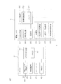
- FIG. 2 is a block diagram showing an electrical configuration of a work vehicle and a management server provided in the work machine management system.
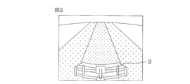
- FIG. 3 is a schematic view showing an example of a photographed image acquired by the photographing unit of the work vehicle.
- FIG. 4 is a schematic view of an image displayed on the external terminal when the user browses the captured image stored in the storage unit provided in the management server using the external terminal. It is a schematic diagram of an image for selecting a type.
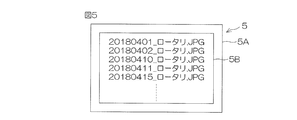
- FIG. 5 is a schematic diagram of an image displayed on the external terminal when the user browses the captured image stored in the storage unit provided in the management server using the external terminal. It is a schematic diagram of an image for selecting an image.
- FIG. 1 is a schematic diagram showing a configuration of a work machine management system 1 according to an embodiment of the present invention.
- the work machine management system 1 is a system that manages information about a work machine mounted on a tractor as a work vehicle for each user.
- the work machine management system 1 describes a tractor 2 as a work vehicle on which the work machine 3 is mounted, a management server 4 that manages information about the work machine 3, an external terminal 5 that can access the management server 4, and a tractor 2. Includes a remote control terminal 7 on which various information of the above is displayed.
- the tractor 2 is capable of manual running and autonomous running (automatic running).
- the operator may be configured to autonomously drive the tractor 2 without boarding the tractor 2. Further, the tractor 2 may be configured so that it can autonomously travel while the tractor 2 is on board.
- working machine 3 for example, various working machines such as a roll baler, a rotary, a plow, a leveler, a mower, a sowing machine, a harvester, and a sprayer can be used.
- various working machines such as a roll baler, a rotary, a plow, a leveler, a mower, a sowing machine, a harvester, and a sprayer can be used.
- the tractor 2, the external terminal 5, and the remote control terminal 7 can wirelessly communicate with the management server 4 via the communication network 6.
- the management server 4 is provided in the management center.
- the external terminal 5 is operated by the user.
- the external terminal 5 is provided in the user's home or the user's office.
- the tractor 2 can wirelessly communicate with the remote control terminal 7 via WiFi or the like.
- the remote control terminal 7 can generate an automatic traveling route, which is a traveling route when the tractor 2 automatically travels.
- the remote control terminal 7 is an example of an automatic traveling route generation unit.
- the remote control terminal 7 is provided with an operation display unit 7A that displays various information of the tractor 2 and can be operated by the user.
- FIG. 2 is a block diagram showing the electrical configurations of the tractor 2 and the management server 4.
- the tractor 2 includes a tractor control unit 40 that controls the operation of the tractor 2 (movements such as forward, reverse, stop, and turn).
- the tractor control unit 40 includes a microcomputer provided with a CPU and a memory (RAM or the like) 41.
- a wireless communication unit 42, a plurality of controllers 43, and a photographing unit 46 are electrically connected to the tractor control unit 40.
- the wireless communication unit 42 is a communication interface for wireless communication with the management server 4.
- the plurality of controllers 43 control each part of the tractor 2.
- the plurality of controllers 43 include an engine controller that controls the number of revolutions of the engine, a vehicle speed controller that controls the vehicle speed of the tractor 2, a steering controller that controls the direction of the tractor 2, and an ascending / descending control of the work equipment 3.
- an elevating controller a PTO controller that controls the rotation of the PTO shaft that transmits power to the work equipment 3, and the like.
- the satellite signal receiving antenna 44 is electrically connected to the tractor control unit 40.
- the satellite signal receiving antenna 44 receives a signal from a positioning satellite (not shown) constituting the satellite positioning system.
- the satellite positioning system is, for example, GNSS (Global Navigation Satellite System).
- the positioning signal received by the satellite signal receiving antenna 44 is input to the positioning data acquisition unit 45.
- the positioning data acquisition unit 45 acquires the positioning data of the tractor 2 at predetermined intervals (for example, 1 second intervals).
- the positioning data includes position information (for example, latitude / longitude information) of the tractor 2 (strictly speaking, the satellite signal receiving antenna 44) and time information corresponding to the position information.
- the positioning data acquisition unit 45 is an example of a position information acquisition unit.
- the photographing unit 46 photographs the working machine 3 mounted on the tractor 2 and acquires shooting data.
- the photographing unit 46 is, for example, a camera.
- the photographing unit 46 is attached to the rear portion of the tractor 2 and photographs the rear lower portion of the tractor 2.
- the shooting data includes a shooting image and a time (shooting time information) when the shooting image is acquired by the shooting unit 46.
- the captured image may be a still image or a moving image.
- FIG. 3 is a schematic view showing an example of a captured image.
- the captured image includes an image of the working machine 3 and an image of a region behind the working machine 3 in the field.
- the shooting time information may be specified based on the time information included in the positioning data acquired by the positioning data acquisition unit 45, or may be the internal time of the tractor 2.
- the photographing unit 46 acquires photography data when the engine of the tractor 2 (not shown) is started, for example.
- the photographing unit 46 may acquire the photographed image once or a plurality of times while the tractor 2 is traveling in the field.
- the wireless communication unit 42 transmits the positioning data and the shooting data to the management server 4 at a predetermined timing.
- the wireless communication unit 42 is an example of a captured image transmission unit and also an example of a position information transmission unit.
- the predetermined timing is, for example, the timing at which the engine (not shown) of the tractor 2 is stopped.
- the wireless communication unit 42 obtains the photographed image acquired while the tractor 2 is traveling in the field at the remote control terminal 7. It is also transmitted (see FIG. 1). As a result, the user can confirm whether or not the work machine 3 is operating normally while the tractor 2 is traveling via the operation display unit 7A of the remote control terminal 7.
- the management server 4 includes a server control unit 60 that controls the management server 4.
- the server control unit 60 includes a microcomputer provided with a CPU and a memory (ROM, RAM, etc.) 61.
- the wireless communication unit 62, the operation display unit 64, the operation unit 65, and the storage unit 63 are electrically connected to the server control unit 60.
- the wireless communication unit 62 is a communication interface for wireless communication with the tractor 2 and the work machine 3.
- the storage unit 63 is composed of a storage device such as a hard disk and a non-volatile memory.
- the operation display unit 64 includes, for example, a touch panel display.
- the operation unit 65 includes, for example, a keyboard, a mouse, and the like.
- the wireless communication unit 62 receives the positioning data and the shooting data transmitted from the wireless communication unit 42 of the tractor 2.
- the server control unit 60 stores the shooting data received by the wireless communication unit 62 in the memory 61.
- the server control unit 60 includes a work machine determination unit 70 that analyzes a photographed image included in the photographed data stored in the memory 61 and determines the type of the work machine 3 in the photographed image. Examples of the analysis method of the captured image include feature quantity analysis using artificial intelligence (AI).
- AI artificial intelligence
- the storage unit 63 includes a positioning data storage unit 66 that stores positioning data, and a shooting data storage unit 67 that stores shooting data together with a discrimination result by the working machine discrimination unit 70.
- the positioning data stored in the positioning data storage unit 66 can be used by the server control unit 60 to generate a movement locus of the tractor 2. After performing the work using the tractor 2, the user accesses the management server 4 using the remote control terminal 7 or the external terminal 5 to view the movement locus of the tractor 2 generated by the server control unit 60. be able to.
- the shooting data storage unit 67 folders for classifying shooting data are prepared in advance for each type of work machine.
- the shooting data storage unit 67 stores the shooting data in a folder corresponding to the type of working machine determined by the working machine discrimination unit 70.
- a file name including the type of working machine and the shooting time (shooting date) is set as the identification information.
- the user can browse the shooting data stored in the shooting data storage unit 67 by accessing the management server 4 using the external terminal 5.
- 4 and 5 are schematic images displayed on the display unit 5A such as the display of the external terminal 5 when the user browses the photographed data stored in the photographed data storage unit 67 using the external terminal 5. It is a figure.
- the type of work machine (rotary, sprayer, plow, etc.) owned by the user is in the display unit 5A of the external terminal 5. Is displayed in the predetermined display area 5B of.
- the image displayed in the display area 5B of the display unit 5A of the external terminal 5 is changed. And one or more file names of shooting data corresponding to the selected work machine type are displayed.
- FIG. 5 shows an example in the case where the user selects "rotary" as the type of work machine in FIG.
- the file name of the shooting data whose type of working machine is rotary is displayed.
- the captured image corresponding to the file name is displayed in the display area 5B of the display unit 5A of the external terminal 5. For example, if you select the file name "20180410_Rotary.JPG", the images taken by the rotary taken on April 10, 2018 will be displayed.
- the shooting date is included in the file name, but when the shooting unit 46 shoots multiple times in one day, in order to identify the shot image acquired on the same day, It is preferable that the file name includes the shooting time (shooting date and time) instead of the shooting date.
- the user can change the file name to the correct one by operating the external terminal 5. If the operator who operates the management server 4 notices that the content of the captured image and the file name do not match, the operator operates the operation unit 65 or the operation display unit 64 of the management server 4 to obtain the correct file name. It is possible to change to.
- the type of the working machine 3 is determined by analyzing the captured image of the working machine 3 acquired by the photographing unit 46 by the working machine discrimination unit 70 of the server control unit 60 of the management server 4. To. Therefore, the type of the working machine 3 can be easily identified without attaching a component for identifying the type of the working machine 3 to each working machine 3.
- the photographed data is not only determined for the type of the working machine 3, but also whether the working machine 3 is operating normally while the tractor 2 is traveling. It can also be used to confirm whether or not.
- the wireless communication unit 42 of the tractor 2 transmits the shooting time information together with the shot image to the management server 4, and the shooting data storage unit 67 of the storage unit 63 of the management server 4 sends the shooting data (shooting image and shooting time information).
- the shooting data storage unit 67 of the storage unit 63 of the management server 4 sends the shooting data (shooting image and shooting time information).
- the shooting data is acquired while the tractor 2 is running, the state of the field during work can be confirmed by referring to the shooting data.
- the wireless communication unit 42 that transmits the positioning data to the management server 4 also transmits the shooting data to the management server 4. Therefore, the wireless communication unit 42 can also be used as the image information transmission unit.
- the working machine discrimination unit 70 may be able to discriminate not only the type of the working machine 3 but also the model of the working machine 3 by analyzing the captured image. If this is the case, the working machine 3 mounted on the tractor 2 can be determined in detail.
- the storage unit 63 of the management server 4 includes a work machine information storage unit 68 (see the two-point chain line in FIG. 2) that stores the work machine information necessary for generating the automatic traveling route for each model of the work machine 3. If the wireless communication unit 62 is configured to transmit the work machine information corresponding to the model of the work machine 3 to the remote control terminal 7, the remote control terminal 7 will be based on the work machine information. An automatic travel route can be generated.
- the work machine information includes, for example, the dimensions of the work machine 3 in the width direction.
- the remote control terminal 7 can acquire the work machine information, it can generate an automatic traveling route so that the work machine 3 can work in the work area of the field without waste. Therefore, the type and model of the working machine 3 can be easily determined, and the information necessary for generating the automatic traveling route can be given to the tractor 2 based on the result.
- the shooting data is acquired by the photographing unit 46, the model of the working machine 3 is determined based on the shot image, before the tractor 2 starts the automatic running. Then, it is necessary to transmit the work machine information to the tractor 2.
- the work machine management system 1 is configured so that the user accesses the management server 4 using the external terminal 5.
- the work machine management system 1 may be configured so that the user can access the management server 4 by using the remote control terminal 7 instead of the external terminal 5.
- the images shown in FIGS. 4 and 5 are displayed on the operation display unit 7A (see FIG. 1) of the remote control terminal 7.
- the photographing unit 46 is attached to the rear portion of the tractor 2. However, if the working machine 3 is mounted in front of the tractor 2, the photographing unit 46 may be mounted in the front portion of the tractor 2.
- Work equipment management system 2 Tractor (work vehicle) 3: Working machine 4: Management server 7: Remote control terminal (automatic driving route generator) 42: Wireless communication unit (captured image transmission unit, position information transmission unit) 45: Positioning data acquisition unit (position information acquisition unit) 58: Location information calculation unit (location information acquisition unit) 62: Wireless communication unit (working machine information transmission unit) 63: Storage unit 68: Working machine information storage unit 70: Working machine discrimination unit
Landscapes
- Life Sciences & Earth Sciences (AREA)
- Engineering & Computer Science (AREA)
- Business, Economics & Management (AREA)
- General Business, Economics & Management (AREA)
- Agronomy & Crop Science (AREA)
- Economics (AREA)
- Human Resources & Organizations (AREA)
- Strategic Management (AREA)
- Computing Systems (AREA)
- Animal Husbandry (AREA)
- Marine Sciences & Fisheries (AREA)
- Mining & Mineral Resources (AREA)
- Health & Medical Sciences (AREA)
- General Health & Medical Sciences (AREA)
- Accounting & Taxation (AREA)
- Marketing (AREA)
- Primary Health Care (AREA)
- Development Economics (AREA)
- Tourism & Hospitality (AREA)
- Physics & Mathematics (AREA)
- General Physics & Mathematics (AREA)
- Theoretical Computer Science (AREA)
- Mechanical Engineering (AREA)
- Soil Sciences (AREA)
- Environmental Sciences (AREA)
- Agricultural Machines (AREA)
- Management, Administration, Business Operations System, And Electronic Commerce (AREA)
- Guiding Agricultural Machines (AREA)
Abstract
作業機管理システムは、作業機が装着される作業車両と、前記作業機を管理する管理サーバとを含む。前記作業車両は、前記作業車両に装着された作業機を撮影して撮影画像を取得する撮影部と、前記撮影画像を前記管理サーバに送信する撮影画像送信部とを有する。前記管理サーバは、前記撮影画像を解析して少なくとも前記作業車両に装着された作業機の種類を判別する作業機判別部を有する。
Description
本発明は、作業機管理システムに関する。
トラクタに作業機を装着して作業を行う場合に、トラクタに装着されている作業機の種類や型式を自動的に判定する技術として、下記特許文献1が開示されている。
下記特許文献1に開示された技術では、作業機には、作業機の識別情報を送信するRFID(Radio Frequency Identification)タグが取り付けられており、作業車両には、RFIDタグが送信する識別情報を受信するRFIDリーダが取り付けられている。そのため、作業車両に装着された作業機のRFIDタグをRFIDリーダが読み取ることで、作業車両に装着中の作業機の種類を把握することができる。
特許文献1に開示された技術では、装着され得る様々な作業機にRFIDタグを準備し、RFIDリーダが読取可能とする取付位置にRFIDタグを正確に取り付ける必要があるため、手間がかかる。
そこで、この発明の目的は、作業車両に装着される作業機を簡単に識別することができる作業機管理システムを提供することである。
この発明の一実施形態は、作業機が装着される作業車両と、前記作業機を管理する管理サーバとを含む作業機管理システムを提供する。前記作業車両が、前記作業車両に装着された作業機を撮影して撮影画像を取得する撮影部と、前記撮影画像を前記管理サーバに送信する撮影画像送信部とを有する。そして、前記管理サーバが、前記撮影画像を解析して少なくとも前記作業車両に装着された作業機の種類を判別する作業機判別部を有する。
この構成によれば、作業車両の撮影部によって取得された撮影画像が管理サーバの作業機判別部によって解析されることによって、作業機の種類が判別される。そのため、作業機の種類を識別するための部品を個々の作業機に取り付けることなく、作業車両に装着される作業機の種類を簡単に判別することができる。
この発明の一実施形態では、前記撮影画像送信部が、前記撮影画像が撮影された時刻を示す撮影時刻情報を前記管理サーバに送信する。そして、前記管理サーバが、前記撮影画像および前記撮影時刻情報を、前記作業機の種類毎に記憶する記憶部を有する。そのため、記憶部に記憶された画像情報および撮影時刻情報を参照することで、各作業が行われた日時を把握することができる。
この発明の一実施形態では、前記作業車両が、前記作業車両の位置情報を取得する位置情報取得部と、前記位置情報を前記管理サーバに送信する位置情報送信部とを有し、前記位置情報送信部が、前記撮影画像送信部である。
この構成によれば、位置情報取得部によって取得された作業車両の位置情報を管理サーバに送信する位置情報送信部を、画像情報送信部に兼用することができる。
この発明の一実施形態では、前記作業機が装着された前記作業車両を自動走行させる自動走行経路を生成する自動走行経路生成部をさらに含む。前記作業機判別部が、前記撮影画像を解析して、前記作業機の種類とともに前記作業機の型式を判別する。そして、前記管理サーバが、前記作業機の型式毎に異なり前記自動走行経路の生成に必要な前記作業機の情報である作業機情報を、前記作業機の型式毎に記憶する作業機情報記憶部と、前記作業機判別部が判別した前記作業機の型式に対応する前記作業機情報を、前記自動走行経路生成部に送信する作業機情報送信部とを有する。
この構成によれば、画像情報の解析によって判別された作業機の型式に対応する作業機情報が作業車両に送信される。そのため、自動走行経路生成部は、作業機情報に基づいて自動走行経路を生成することができる。したがって、作業機の種類および型式を簡単に判別し、その結果に基づいて、自動走行経路の生成に必要な作業機情報を自動走行経路生成部に与えることができる。
本発明における上述の、またはさらに他の目的、特徴および効果は、添付図面を参照して次に述べる実施形態の説明により明らかにされる。
図1は、本発明の一実施形態に係る作業機管理システム1の構成を示す模式図である。作業機管理システム1は、作業車両としてのトラクタに装着される作業機に関する情報をユーザ毎に管理するシステムである。
作業機管理システム1は、作業機3が装着される作業車両としてのトラクタ2と、作業機3に関する情報を管理する管理サーバ4と、管理サーバ4にアクセス可能な外部端末5と、トラクタ2についての各種情報が表示される遠隔操作端末7とを含む。
トラクタ2は、手動走行および自律走行(自動走行)が可能にされている。オペレータは、トラクタ2に搭乗することなくトラクタ2を自律走行させることができるように構成されていてもよい。また、このトラクタ2は、トラクタ2が搭乗した状態で自律走行を行えるように構成されていてもよい。
作業機3としては、たとえば、ロールベーラ、ロータリ、プラウ、レベラ、草刈機、播種機、収穫機、スプレーヤ等の種々の作業機を用いることができる。
トラクタ2、外部端末5および遠隔操作端末7は、通信網6を介して、管理サーバ4と無線通信可能である。管理サーバ4は、管理センター内に設けられている。外部端末5は、ユーザによって操作される。外部端末5は、ユーザの家やユーザの事務所に設けられている。
トラクタ2は、遠隔操作端末7とWiFi等で無線通信可能である。遠隔操作端末7は、トラクタ2が自動走行する際の走行経路である自動走行経路を生成することができる。遠隔操作端末7は、自動走行経路生成部の一例である。遠隔操作端末7には、トラクタ2の各種情報が表示されユーザが操作可能な操作表示部7Aが設けられている。
図2は、トラクタ2および管理サーバ4の電気的構成を示すブロック図である。トラクタ2は、トラクタ2の動作(前進、後進、停止、旋回等の動作)を制御するトラクタ制御部40を含む。トラクタ制御部40は、CPUおよびメモリ(RAM等)41を備えたマイクロコンピュータを含む。トラクタ制御部40には、無線通信部42、複数のコントローラ43および撮影部46が電気的に接続されている。無線通信部42は、管理サーバ4と無線通信するための通信インターフェースである。
複数のコントローラ43は、トラクタ2の各部を制御する。具体的には、複数のコントローラ43には、エンジンの回転数を制御するエンジンコントローラ、トラクタ2の車速を制御する車速コントローラ、トラクタ2の向きを制御する操向コントローラ、作業機3の昇降を制御する昇降コントローラ、作業機3に動力を伝達するPTO軸の回転を制御するPTOコントローラ等が含まれる。
トラクタ制御部40には、衛星信号受信用アンテナ44が電気的に接続されている。衛星信号受信用アンテナ44は、衛星測位システムを構成する測位衛星(図示せず)からの信号を受信するものである。衛星測位システムは、たとえば、GNSS(Global Navigation Satellite System)である。衛星信号受信用アンテナ44で受信された測位信号は、測位データ取得部45に入力される。
測位データ取得部45は、トラクタ2の測位データを所定の間隔(たとえば、1秒間隔)で取得する。測位データには、トラクタ2(厳密には、衛星信号受信用アンテナ44)の位置情報(たとえば緯度・経度情報)と、位置情報に対応する時刻情報とが含まれる。測位データ取得部45は、位置情報取得部の一例である。
撮影部46は、トラクタ2に装着された作業機3を撮影して撮影データを取得する。撮影部46は、たとえば、カメラである。撮影部46は、トラクタ2の後方部分に取り付けられており、トラクタ2の後下方を撮影する。
撮影データには、撮影画像と、撮影部46によって撮影画像が取得されたときの時刻(撮影時刻情報)とが含まれる。撮影画像は、静止画像であってもよいし、動画像であってもよい。図3は、撮影画像の一例を示す模式図である。撮影画像には、作業機3の画像、および、圃場において作業機3よりも後方の領域の画像が含まれる。
撮影時刻情報は、測位データ取得部45によって取得される測位データに含まれる時刻情報に基づいて特定されてもよいし、トラクタ2の内部時刻であってもよい。
撮影部46は、たとえば、トラクタ2のエンジン(図示せず)の始動時に撮影データを取得する。撮影部46は、圃場でのトラクタ2の走行中にも撮影画像を1回または複数回取得してもよい。
無線通信部42は、測位データおよび撮影データを所定のタイミングで管理サーバ4に送信する。無線通信部42は、撮影画像送信部の一例であり、位置情報送信部の一例でもある。所定のタイミングとは、たとえば、トラクタ2のエンジン(図示せず)が停止するタイミングである。
圃場でのトラクタ2の走行中にも撮影部46によって撮影画像が取得されている場合には、無線通信部42は、圃場でのトラクタ2の走行中に取得された撮影画像を遠隔操作端末7(図1を参照)にも送信する。これにより、ユーザは、遠隔操作端末7の操作表示部7Aを介して、トラクタ2の走行中に作業機3が正常に動作しているか否かを確認することができる。
管理サーバ4は、管理サーバ4を制御するサーバ制御部60を含む。サーバ制御部60は、CPUおよびメモリ(ROM、RAM等)61を備えたマイクロコンピュータを含む。サーバ制御部60には、無線通信部62、操作表示部64、操作部65および記憶部63が電気的に接続されている。
無線通信部62は、トラクタ2や作業機3と無線通信するための通信インターフェースである。記憶部63は、ハードディスク、不揮発性メモリ等の記憶デバイスから構成されている。操作表示部64は、たとえば、タッチパネル式ディスプレイからなる。操作部65は、たとえば、キーボード、マウス等を含む。
無線通信部62は、トラクタ2の無線通信部42から送信された測位データおよび撮影データを受信する。サーバ制御部60は、無線通信部62が受信した撮影データをメモリ61に保存する。サーバ制御部60は、メモリ61に保存された撮影データに含まれる撮影画像を解析して、撮影画像中の作業機3の種類を判別する作業機判別部70を含む。撮影画像の解析手法としては、たとえば、人工知能(AI:artificial intelligence)を用いた特徴量解析が挙げられる。
記憶部63は、測位データを記憶する測位データ記憶部66と、作業機判別部70による判別結果とともに撮影データを記憶する撮影データ記憶部67とを含む。
測位データ記憶部66に記憶された測位データは、サーバ制御部60がトラクタ2の移動軌跡を生成するために用いることができる。ユーザは、トラクタ2を用いて作業を行った後、遠隔操作端末7または外部端末5を用いて管理サーバ4にアクセスすることによって、サーバ制御部60によって生成されたトラクタ2の移動軌跡を閲覧することができる。
撮影データ記憶部67には、撮影データを分類するフォルダが作業機の種類毎に予め用意されている。撮影データ記憶部67は、作業機判別部70によって判別された作業機の種類に対応するフォルダに撮影データを記憶する。撮影データ記憶部67に記憶された撮影データには、識別情報として、作業機の種類および撮影時刻(撮影日)を含むファイル名が設定される。
ユーザは、外部端末5を用いて管理サーバ4にアクセスすることによって、撮影データ記憶部67に記憶された撮影データを閲覧することができる。図4および図5は、撮影データ記憶部67に記憶された撮影データを、外部端末5を用いてユーザが閲覧する際に、外部端末5のディスプレイ等の表示部5Aに表示される画像の模式図である。
ユーザは、外部端末5を用いて管理サーバ4にアクセスすると、図4に示すように、ユーザ自身が所有する作業機の種類(ロータリ、スプレーヤ、プラウ等)が、外部端末5の表示部5A内の所定の表示領域5Bに表示される。ユーザが外部端末5の表示部5Aの内の表示領域5Bに表示される複数の作業機種のうちから1つを選択すると、外部端末5の表示部5Aの表示領域5Bに表示される画像が変更され、選択した作業機の種類に対応する撮影データのファイル名が1つまたは複数表示される。
図5には、図4においてユーザが作業機の種類として「ロータリ」を選択した場合の例が示されている。図5に示す例では、作業機の種類がロータリである撮影データのファイル名が表示される。外部端末5の表示部5Aの表示領域5Bに表示されたファイル名を選択すると、そのファイル名に対応する撮影画像が外部端末5の表示部5Aの表示領域5Bに表示される。たとえば、「20180410_ロータリ.JPG」というファイル名を選択すると、2018年4月10日に撮影されたロータリの撮影画像が表示される。
図5に示す例では、ファイル名には撮影日が含まれているが、撮影部46が1日のうちに複数回撮影する場合には、同日に取得された撮影画像を識別するために、撮影日ではなく、撮影時刻(撮影日時)がファイル名に含まれることが好ましい。
仮に、撮影画像の内容とファイル名とが整合していない場合には、ユーザが外部端末5を操作することによって、正しいファイル名に変更することができる。管理サーバ4を操作するオペレータが撮影画像の内容とファイル名とが整合していないことに気付いた場合には、オペレータが管理サーバ4の操作部65または操作表示部64を操作して正しいファイル名に変更することが可能である。
この実施形態によれば、撮影部46によって取得された作業機3の撮影画像が管理サーバ4のサーバ制御部60の作業機判別部70によって解析されることによって、作業機3の種類が判別される。そのため、作業機3の種類を識別するための部品を個々の作業機3に取り付けることなく、作業機3の種類を簡単に判別することができる。
また、トラクタ2の走行中に撮影部46によって撮影データを取得すれば、撮影データを、作業機3の種別の判別だけでなく、トラクタ2の走行中に作業機3が正常に動作しているか否かの確認にも利用することができる。
また、トラクタ2の無線通信部42が、撮影画像とともに撮影時刻情報を管理サーバ4に送信し、管理サーバ4の記憶部63の撮影データ記憶部67が、撮影データ(撮影画像および撮影時刻情報)を記憶する。そのため、撮影データ記憶部67に記憶された撮影データを参照することで各作業が行われた日時を把握することができる。
また、撮影データが、トラクタ2の走行中に取得されたものであれば、撮影データを参照することで、作業中の圃場の状態を確認することもできる。
また、トラクタ2において、管理サーバ4に向けて測位データを送信する無線通信部42が、管理サーバ4に向けて撮影データも送信する。そのため、無線通信部42を、画像情報送信部に兼用することができる。
この発明は、以上に説明した実施形態に限定されるものではなく、さらに他の形態で実施することができる。
たとえば、作業機判別部70は、撮影画像を解析することによって、作業機3の種類だけでなく作業機3の型式を判別可能であってもよい。そうであれば、トラクタ2に装着される作業機3を詳しく判別することができる。
さらに、管理サーバ4の記憶部63が、自動走行経路の生成に必要な作業機情報を作業機3の型式毎に記憶する作業機情報記憶部68(図2の二点鎖線を参照)を含んでおり、かつ、無線通信部62が、作業機3の型式に対応する作業機情報を遠隔操作端末7に送信するように構成されていれば、遠隔操作端末7は、作業機情報に基づいて自動走行経路を生成することができる。作業機情報には、たとえば、幅方向における作業機3の寸法等が含まれる。
遠隔操作端末7は、作業機情報を取得することができれば、圃場の作業領域において作業機3が無駄なく作業可能なように、自動走行経路を生成することができる。したがって、作業機3の種類および型式を簡単に判別し、その結果に基づいて、自動走行経路の生成に必要な情報をトラクタ2に与えることができる。
ただし、自動走行経路の生成に作業機情報を利用する場合には、トラクタ2が自動走行を開始する前に、撮影部46による撮影データの取得、撮影画像に基づく作業機3の型式の判別、および、トラクタ2への作業機情報の送信が行われる必要がある。
上述の実施形態に係る作業機管理システム1では、ユーザが外部端末5を用いて管理サーバ4にアクセスするように構成されている。しかしながら、ユーザが、外部端末5の代わりに、遠隔操作端末7を用いて管理サーバ4にアクセスできるように作業機管理システム1が構成されていてもよい。この場合、図4および図5に示す画像は、遠隔操作端末7の操作表示部7A(図1参照)に表示される。
上述の実施形態に係る作業機管理システム1では、撮影部46がトラクタ2の後方部分に取り付けられている。しかしながら、トラクタ2の前方に作業機3が装着される構成であれば、撮影部46がトラクタ2の前方部分に取り付けられていてもよい。
本発明の実施形態について詳細に説明してきたが、これらは本発明の技術的内容を明らかにするために用いられた具体例に過ぎず、本発明はこれらの具体例に限定して解釈されるべきではなく、本発明の範囲は添付の請求の範囲によってのみ限定される。
この出願は、2019年3月26日に日本国特許庁に提出された特願2019-058821号に対応しており、この出願の全開示はここに引用により組み込まれるものとする。
1 :作業機管理システム
2 :トラクタ(作業車両)
3 :作業機
4 :管理サーバ
7 :遠隔操作端末(自動走行経路生成部)
42 :無線通信部(撮影画像送信部、位置情報送信部)
45 :測位データ取得部(位置情報取得部)
58 :位置情報算出部(位置情報取得部)
62 :無線通信部(作業機情報送信部)
63 :記憶部
68 :作業機情報記憶部
70 :作業機判別部
2 :トラクタ(作業車両)
3 :作業機
4 :管理サーバ
7 :遠隔操作端末(自動走行経路生成部)
42 :無線通信部(撮影画像送信部、位置情報送信部)
45 :測位データ取得部(位置情報取得部)
58 :位置情報算出部(位置情報取得部)
62 :無線通信部(作業機情報送信部)
63 :記憶部
68 :作業機情報記憶部
70 :作業機判別部
Claims (4)
- 作業機が装着される作業車両と、前記作業機を管理する管理サーバとを含む作業機管理システムであって、
前記作業車両が、前記作業車両に装着された作業機を撮影して撮影画像を取得する撮影部と、前記撮影画像を前記管理サーバに送信する撮影画像送信部とを有し、
前記管理サーバが、前記撮影画像を解析して少なくとも前記作業車両に装着された作業機の種類を判別する作業機判別部を有する、作業機管理システム。 - 前記撮影画像送信部が、前記撮影画像が撮影された時刻を示す撮影時刻情報を前記管理サーバに送信し、
前記管理サーバが、前記撮影画像および前記撮影時刻情報を、前記作業機の種類毎に記憶する記憶部を有する、請求項1に記載の作業機管理システム。 - 前記作業車両が、前記作業車両の位置情報を取得する位置情報取得部と、前記位置情報を前記管理サーバに送信する位置情報送信部とを有し、
前記位置情報送信部が、前記撮影画像送信部である、請求項1または2に記載の作業機管理システム。 - 前記作業機が装着された前記作業車両を自動走行させる自動走行経路を生成する自動走行経路生成部をさらに含み、
前記作業機判別部が、前記撮影画像を解析して、前記作業機の種類とともに前記作業機の型式を判別し、
前記管理サーバが、前記作業機の型式毎に異なり前記自動走行経路の生成に必要な前記作業機の情報である作業機情報を、前記作業機の型式毎に記憶する作業機情報記憶部と、前記作業機判別部が判別した前記作業機の型式に対応する前記作業機情報を、前記自動走行経路生成部に送信する作業機情報送信部とを有する、請求項1~3のいずれか一項に記載の作業機管理システム。
Applications Claiming Priority (2)
| Application Number | Priority Date | Filing Date | Title |
|---|---|---|---|
| JP2019-058821 | 2019-03-26 | ||
| JP2019058821A JP7150653B2 (ja) | 2019-03-26 | 2019-03-26 | 作業機管理システム |
Publications (1)
| Publication Number | Publication Date |
|---|---|
| WO2020195146A1 true WO2020195146A1 (ja) | 2020-10-01 |
Family
ID=72609988
Family Applications (1)
| Application Number | Title | Priority Date | Filing Date |
|---|---|---|---|
| PCT/JP2020/003492 Ceased WO2020195146A1 (ja) | 2019-03-26 | 2020-01-30 | 作業機管理システム |
Country Status (2)
| Country | Link |
|---|---|
| JP (1) | JP7150653B2 (ja) |
| WO (1) | WO2020195146A1 (ja) |
Cited By (1)
| Publication number | Priority date | Publication date | Assignee | Title |
|---|---|---|---|---|
| EP4487668A1 (en) * | 2023-06-29 | 2025-01-08 | Kubota Corporation | Method and system for estimating the type of implement connected to a work vehicle |
Families Citing this family (2)
| Publication number | Priority date | Publication date | Assignee | Title |
|---|---|---|---|---|
| KR102748359B1 (ko) * | 2023-12-27 | 2024-12-31 | 주식회사 대동 | 작업기 자동 인식 기능을 갖는 농기계 자율 주행 시스템과 그 제어 방법 |
| WO2025142094A1 (ja) * | 2023-12-28 | 2025-07-03 | 株式会社クボタ | 情報表示システム、作業車両および表示制御方法 |
Citations (4)
| Publication number | Priority date | Publication date | Assignee | Title |
|---|---|---|---|---|
| JP2006296261A (ja) * | 2005-04-19 | 2006-11-02 | Mitsubishi Agricult Mach Co Ltd | 農業機械 |
| WO2015118730A1 (ja) * | 2014-02-06 | 2015-08-13 | ヤンマー株式会社 | 併走作業システムの遠隔操作装置 |
| JP2017212941A (ja) * | 2016-06-01 | 2017-12-07 | 井関農機株式会社 | 作業車両の管理システム |
| US20180165502A1 (en) * | 2016-12-13 | 2018-06-14 | Caterpillar Inc. | Vehicle Classification and Vehicle Pose Estimation |
-
2019
- 2019-03-26 JP JP2019058821A patent/JP7150653B2/ja active Active
-
2020
- 2020-01-30 WO PCT/JP2020/003492 patent/WO2020195146A1/ja not_active Ceased
Patent Citations (4)
| Publication number | Priority date | Publication date | Assignee | Title |
|---|---|---|---|---|
| JP2006296261A (ja) * | 2005-04-19 | 2006-11-02 | Mitsubishi Agricult Mach Co Ltd | 農業機械 |
| WO2015118730A1 (ja) * | 2014-02-06 | 2015-08-13 | ヤンマー株式会社 | 併走作業システムの遠隔操作装置 |
| JP2017212941A (ja) * | 2016-06-01 | 2017-12-07 | 井関農機株式会社 | 作業車両の管理システム |
| US20180165502A1 (en) * | 2016-12-13 | 2018-06-14 | Caterpillar Inc. | Vehicle Classification and Vehicle Pose Estimation |
Cited By (1)
| Publication number | Priority date | Publication date | Assignee | Title |
|---|---|---|---|---|
| EP4487668A1 (en) * | 2023-06-29 | 2025-01-08 | Kubota Corporation | Method and system for estimating the type of implement connected to a work vehicle |
Also Published As
| Publication number | Publication date |
|---|---|
| JP2020160740A (ja) | 2020-10-01 |
| JP7150653B2 (ja) | 2022-10-11 |
Similar Documents
| Publication | Publication Date | Title |
|---|---|---|
| EP3618011B1 (en) | Data collection apparatus, on-vehicle device, data collection system, and data collection method | |
| US11797025B2 (en) | Autonomous work system, autonomous work setting method, and storage medium | |
| WO2020195146A1 (ja) | 作業機管理システム | |
| KR102014761B1 (ko) | 공간객체 검색결과 정렬 방법, 시스템 및 컴퓨터 독취가능 저장장치 | |
| US12487611B2 (en) | Automatic traveling system, automatic traveling method, and automatic traveling program | |
| US20040064479A1 (en) | Image information management system | |
| US10757315B2 (en) | Vehicle imaging support device, method, and program storage medium | |
| EP4295655A1 (en) | Display method, display terminal, and display program | |
| CN108458712A (zh) | 无人驾驶小车导航系统及导航方法、无人驾驶小车 | |
| EP3769598B1 (en) | Placement position notification system | |
| EP4265091B1 (en) | Automatic traveling system, automatic traveling method, and automatic traveling program | |
| JP6773523B2 (ja) | 圃場登録システム | |
| CN110825106B (zh) | 一种飞行器的避障方法、飞行器、飞行系统及存储介质 | |
| JP2012019374A (ja) | 電子アルバム作成サーバー、情報処理装置、電子アルバム作成システム、及び、電子アルバム作成サーバーの制御方法 | |
| US20200242861A1 (en) | Management apparatus, control method for management apparatus, and non-transitory computer-readable storage medium | |
| CN110574365B (zh) | 图像生成装置以及图像生成方法 | |
| JP2014011687A (ja) | 自走式撮影装置、制御プログラム、および、制御プログラムを記録したコンピュータ読み取り可能な記録媒体 | |
| CN112528699B (zh) | 用于获得场景中的设备或其用户的标识信息的方法和系统 | |
| CN115129042A (zh) | 用于自主作业机器许可的系统和方法 | |
| CN113470047A (zh) | 点云的处理方法和装置 | |
| JP2019066191A (ja) | 情報処理装置 | |
| CN118471011A (zh) | 基于嵌入距离模型的检测网络 | |
| US12290015B2 (en) | Work assistance system, work system, work assistance method, and program | |
| JP7057468B1 (ja) | 管理システム、管理方法及びプログラム | |
| JP2022152550A (ja) | 遠隔運転代行システム、制御方法、及びプログラム |
Legal Events
| Date | Code | Title | Description |
|---|---|---|---|
| 121 | Ep: the epo has been informed by wipo that ep was designated in this application |
Ref document number: 20779178 Country of ref document: EP Kind code of ref document: A1 |
|
| NENP | Non-entry into the national phase |
Ref country code: DE |
|
| 122 | Ep: pct application non-entry in european phase |
Ref document number: 20779178 Country of ref document: EP Kind code of ref document: A1 |