WO2020194847A1 - 自動変速機 - Google Patents
自動変速機 Download PDFInfo
- Publication number
- WO2020194847A1 WO2020194847A1 PCT/JP2019/044468 JP2019044468W WO2020194847A1 WO 2020194847 A1 WO2020194847 A1 WO 2020194847A1 JP 2019044468 W JP2019044468 W JP 2019044468W WO 2020194847 A1 WO2020194847 A1 WO 2020194847A1
- Authority
- WO
- WIPO (PCT)
- Prior art keywords
- control valve
- valve assembly
- automatic transmission
- drain port
- pressure
- Prior art date
- Legal status (The legal status is an assumption and is not a legal conclusion. Google has not performed a legal analysis and makes no representation as to the accuracy of the status listed.)
- Ceased
Links
Images


Classifications
-
- F—MECHANICAL ENGINEERING; LIGHTING; HEATING; WEAPONS; BLASTING
- F16—ENGINEERING ELEMENTS AND UNITS; GENERAL MEASURES FOR PRODUCING AND MAINTAINING EFFECTIVE FUNCTIONING OF MACHINES OR INSTALLATIONS; THERMAL INSULATION IN GENERAL
- F16H—GEARING
- F16H61/00—Control functions within control units of change-speed- or reversing-gearings for conveying rotary motion ; Control of exclusively fluid gearing, friction gearing, gearings with endless flexible members or other particular types of gearing
- F16H61/02—Control functions within control units of change-speed- or reversing-gearings for conveying rotary motion ; Control of exclusively fluid gearing, friction gearing, gearings with endless flexible members or other particular types of gearing characterised by the signals used
- F16H61/0262—Control functions within control units of change-speed- or reversing-gearings for conveying rotary motion ; Control of exclusively fluid gearing, friction gearing, gearings with endless flexible members or other particular types of gearing characterised by the signals used the signals being hydraulic
- F16H61/0276—Elements specially adapted for hydraulic control units, e.g. valves
-
- F—MECHANICAL ENGINEERING; LIGHTING; HEATING; WEAPONS; BLASTING
- F16—ENGINEERING ELEMENTS AND UNITS; GENERAL MEASURES FOR PRODUCING AND MAINTAINING EFFECTIVE FUNCTIONING OF MACHINES OR INSTALLATIONS; THERMAL INSULATION IN GENERAL
- F16H—GEARING
- F16H61/00—Control functions within control units of change-speed- or reversing-gearings for conveying rotary motion ; Control of exclusively fluid gearing, friction gearing, gearings with endless flexible members or other particular types of gearing
- F16H61/0003—Arrangement or mounting of elements of the control apparatus, e.g. valve assemblies or snapfittings of valves; Arrangements of the control unit on or in the transmission gearbox
- F16H61/0009—Hydraulic control units for transmission control, e.g. assembly of valve plates or valve units
-
- F—MECHANICAL ENGINEERING; LIGHTING; HEATING; WEAPONS; BLASTING
- F16—ENGINEERING ELEMENTS AND UNITS; GENERAL MEASURES FOR PRODUCING AND MAINTAINING EFFECTIVE FUNCTIONING OF MACHINES OR INSTALLATIONS; THERMAL INSULATION IN GENERAL
- F16K—VALVES; TAPS; COCKS; ACTUATING-FLOATS; DEVICES FOR VENTING OR AERATING
- F16K27/00—Construction of housing; Use of materials therefor
- F16K27/04—Construction of housing; Use of materials therefor of sliding valves
-
- F—MECHANICAL ENGINEERING; LIGHTING; HEATING; WEAPONS; BLASTING
- F16—ENGINEERING ELEMENTS AND UNITS; GENERAL MEASURES FOR PRODUCING AND MAINTAINING EFFECTIVE FUNCTIONING OF MACHINES OR INSTALLATIONS; THERMAL INSULATION IN GENERAL
- F16H—GEARING
- F16H61/00—Control functions within control units of change-speed- or reversing-gearings for conveying rotary motion ; Control of exclusively fluid gearing, friction gearing, gearings with endless flexible members or other particular types of gearing
- F16H61/02—Control functions within control units of change-speed- or reversing-gearings for conveying rotary motion ; Control of exclusively fluid gearing, friction gearing, gearings with endless flexible members or other particular types of gearing characterised by the signals used
- F16H61/0262—Control functions within control units of change-speed- or reversing-gearings for conveying rotary motion ; Control of exclusively fluid gearing, friction gearing, gearings with endless flexible members or other particular types of gearing characterised by the signals used the signals being hydraulic
- F16H61/0276—Elements specially adapted for hydraulic control units, e.g. valves
- F16H2061/0279—Details of hydraulic valves, e.g. lands, ports, spools or springs
Definitions
- the present invention relates to an automatic transmission.
- Patent Document 1 discloses an automatic transmission having a built-in control valve and a control valve assembly having a drain port that communicates with the outside.
- the present invention has been made in view of such technical problems, and an object of the present invention is to provide an automatic transmission provided with a control valve assembly that suppresses large deformation.
- the automatic transmission provided with the control valve assembly of the present invention is characterized in that the control valve assembly is provided with a reinforcing portion straddling a drain port that communicates the inside and the outside of the control valve assembly.
- FIG. 5 is a schematic view seen from the side of an automatic transmission including the control valve assembly of the first embodiment. It is a perspective view seen from the lower body side of the control valve assembly of Embodiment 1.
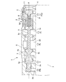
- FIG. 2 is a cross-sectional view taken along the line AA of FIG.
- FIG. 1 is a schematic view of an automatic transmission AT including the control valve assembly 1 of the first embodiment as viewed from the side surface.
- the automatic transmission AT has a control valve assembly 1 having a built-in control valve and a drain port for communicating with the outside, which is composed of a lower body 2 and an upper body 3.
- FIG. 2 is a perspective view of the control valve assembly 1 of the first embodiment as viewed from the lower body side
- FIG. 3 is a sectional view taken along the line AA of FIG.
- the lower body 2 includes a pressure regulator valve (control valve for control) 6 that regulates the line pressure PL that is the main pressure of the hydraulic oil of the automatic transmission AT, and a lockup control valve (control) that controls the operation of a lockup clutch (not shown).
- Control valve) 7 etc. are housed.
- a plurality of solenoids 5 for generating control pressure for controlling the pressure regulator valve 6, the lockup control valve 7, and the like are arranged on the side surface of the lower body 2.
- the lower body 2 of the control valve assembly 1 is integrated with the upper body 3 via a separate plate 4 by a plurality of fastening bolts B.
- the lower body 2 including the pressure regulator valve 6 for adjusting the pressure of the hydraulic oil of the automatic transmission AT is provided with a drain port 2a for adjusting the pressure.
- a rib R on the outer surface of the lower body 2, parallel to the axial center P of the spool 9 of the pressure regulator valve 6) straddling the drain port 2a ( The reinforcing portion) is formed to have a length substantially the same as the axial length of the spool 9.
- a bore 10 is formed inside the lower body 2, and the spool 9 of the pressure regulator valve 6 is housed in the bore 10.
- the adapter 11 is press-fitted and fixed to the right end portion in the drawing.
- the spool 9 is slidably housed in the bore 10 via a spring 8 arranged between the adapter 11 and the land 9d of the spool 9.
- the lower body 2 between the adapter 11 and the land 9d of the spool 9 is formed with a port 2f to which hydraulic oil of the solenoid pressure Psol for line pressure control controlled by the solenoid 5 for line pressure control is supplied.
- a port 2e for supplying the hydraulic oil of the torque converter pressure Pt to a torque converter (not shown) is formed in the lower body 2 between the lands 9d and the lands 9c of the spool 9. Further, the lower body 2 between the lands 9c and the lands 9b of the spool 9 is formed with a port 2d to which the hydraulic oil of the oil pump discharge pressure discharged by the oil pump (not shown) is supplied.
- the spool 9 of the pressure regulator valve 6 is an oil pump due to the balance between the line pressure control solenoid pressure Psol supplied to the port 2f and the urging force of the spring 8 and the feedback pressure Pfb (line pressure PL) supplied to the feedback port 2b.
- the line pressure PL is adjusted and generated by discharging the hydraulic oil of the discharge pressure to the drain port 2a and the port 2e formed in the lower body 2 between the lands 9b and the lands 9a of the spool 9.
- the drain port 2c discharges the leaked hydraulic oil.
- the drain port 2a is closed by the rib R.
- the drain port 2a since the drain port 2a is open in the direction orthogonal to the axial center P of the spool 9, there is no problem with the operation of the pressure regulator valve 6. As a result, the rigidity in the vicinity of the drain port 2a that communicates the inside and the outside of the control valve assembly 1 can be increased, and large deformation can be suppressed.
- the automatic transmission AT including the control valve assembly 1 of the first embodiment has the effects listed below.
- a rib R is formed on the outer surface of the lower body 2 in parallel with the axial center P of the spool 9 of the pressure regulator valve 6 and straddling the drain port 2a having a length substantially the same as the axial length of the spool 9. I made it. Therefore, the rigidity in the vicinity where the drain port 2a is formed can be increased, and large deformation can be suppressed.
Landscapes
- Engineering & Computer Science (AREA)
- General Engineering & Computer Science (AREA)
- Mechanical Engineering (AREA)
- Control Of Transmission Device (AREA)
Abstract
本発明のコントロールバルブアッセンブリ(1)を備える自動変速機では、コントロールバルブアッセンブリ(1)の内部と外部を連通するドレンポート(2a)を跨いだリブ(R)を、コントロールバルブアッセンブリ(1)に設けた。これにより、大きな変形を抑制したコントロールバルブアッセンブリ(1)を備える自動変速機を提供する。
Description
本発明は、自動変速機に関する。
特許文献1には、コントロールバルブを内蔵し、外部と連通するドレンポートを有するコントロールバルブアッセンブリを備える自動変速機が開示されている。
しかしながら、特許文献1のコントロールバルブアッセンブリでは、外部と連通するドレンポート付近の剛性が弱いため、締結用のボルトの軸力や高圧の作動油により、大きく変形するおそれがある。
本発明は、このような技術的課題に鑑みてなされたもので、大きな変形を抑制したコントロールバルブアッセンブリを備える自動変速機を提供することを目的とする。
本発明のコントロールバルブアッセンブリを備える自動変速機では、コントロールバルブアッセンブリの内部と外部を連通するドレンポートを跨いだ補強部を、コントロールバルブアッセンブリに設けたことを特徴とする。
よって、本発明のコントロールバルブアッセンブリを備える自動変速機では、外部と連通するドレンポート付近の剛性を高めたため、大きな変形を抑制することができる。
[実施形態1]
図1は、実施形態1のコントロールバルブアッセンブリ1を備える自動変速機ATの側面から見た模式図である。
図1は、実施形態1のコントロールバルブアッセンブリ1を備える自動変速機ATの側面から見た模式図である。
自動変速機ATは、コントロールバルブを内蔵し、外部と連通するドレンポートを有するロアボディ2とアッパボディ3から構成されるコントロールバルブアッセンブリ1を、その下部に有している。
図2は、実施形態1のコントロールバルブアッセンブリ1のロアボディ側から見た斜視図であり、図3は、図2のA-A断面図である。
ロアボディ2は、自動変速機ATの作動油の元圧となるライン圧PLを調圧するプレッシャレギュレータバルブ(制御用コントロールバルブ)6や不図示のロックアップクラッチの作動を制御するロックアップコントロールバルブ(制御用コントロールバルブ)7等を収容している。
また、プレッシャレギュレータバルブ6やロックアップコントロールバルブ7等を制御するための制御圧を発生する複数のソレノイド5が、ロアボディ2の側面に配置されている。
コントロールバルブアッセンブリ1のロアボディ2は、セパレートプレート4を介してアッパボディ3と、複数の締結用のボルトBにより一体化されている。
また、プレッシャレギュレータバルブ6やロックアップコントロールバルブ7等を制御するための制御圧を発生する複数のソレノイド5が、ロアボディ2の側面に配置されている。
コントロールバルブアッセンブリ1のロアボディ2は、セパレートプレート4を介してアッパボディ3と、複数の締結用のボルトBにより一体化されている。
また、自動変速機ATの作動油の圧力を調整するプレッシャレギュレータバルブ6を収容しているロアボディ2には、圧力を調整するためのドレンポート2aが設けられている。
さらに、ドレンポート2a付近の剛性を高めるため、図3に示すように、ロアボディ2の外表面に、プレッシャレギュレータバルブ6のスプール9の軸心Pに平行に、ドレンポート2aを跨いだリブR(補強部)が、スプール9の軸方向長さとほぼ同様の長さで形成されている。
さらに、ドレンポート2a付近の剛性を高めるため、図3に示すように、ロアボディ2の外表面に、プレッシャレギュレータバルブ6のスプール9の軸心Pに平行に、ドレンポート2aを跨いだリブR(補強部)が、スプール9の軸方向長さとほぼ同様の長さで形成されている。
図3に基づき、プレッシャレギュレータバルブ6の構成を説明する。
ロアボディ2の内部には、ボア10が形成され、このボア10内にプレッシャレギュレータバルブ6のスプール9が収納されている。
ボア10内には、図示右側端部に、アダプタ11が圧入固定されている。
また、アダプタ11とスプール9のランド9d間に配置されたスプリング8を介して、スプール9がボア10内を摺動可能に収納されている。
アダプタ11とスプール9のランド9d間のロアボディ2には、ライン圧制御用のソレノイド5が制御するライン圧制御用ソレノイド圧Psolの作動油が供給されるポート2fが形成されている。
ロアボディ2の内部には、ボア10が形成され、このボア10内にプレッシャレギュレータバルブ6のスプール9が収納されている。
ボア10内には、図示右側端部に、アダプタ11が圧入固定されている。
また、アダプタ11とスプール9のランド9d間に配置されたスプリング8を介して、スプール9がボア10内を摺動可能に収納されている。
アダプタ11とスプール9のランド9d間のロアボディ2には、ライン圧制御用のソレノイド5が制御するライン圧制御用ソレノイド圧Psolの作動油が供給されるポート2fが形成されている。
また、スプール9のランド9dとランド9c間のロアボディ2には、不図示のトルクコンバータへトルクコンバータ圧Ptの作動油を供給するポート2eが形成されている。
さらに、スプール9のランド9cとランド9b間のロアボディ2には、不図示のオイルポンプが吐出するオイルポンプ吐出圧の作動油が供給されるポート2dが形成されている。
プレッシャレギュレータバルブ6のスプール9は、ポート2fに供給されるライン圧制御用ソレノイド圧Psolおよびスプリング8の付勢力とフィードバックポート2bに供給されるフィードバック圧Pfb(ライン圧PL)のバランスにより、オイルポンプ吐出圧の作動油を、スプール9のランド9bとランド9a間のロアボディ2に形成されたドレンポート2aやポート2eに作動油を排出することで、ライン圧PLを調圧、生成している。
なお、ドレンポート2cは、リークしてきた作動油を排出する。
さらに、スプール9のランド9cとランド9b間のロアボディ2には、不図示のオイルポンプが吐出するオイルポンプ吐出圧の作動油が供給されるポート2dが形成されている。
プレッシャレギュレータバルブ6のスプール9は、ポート2fに供給されるライン圧制御用ソレノイド圧Psolおよびスプリング8の付勢力とフィードバックポート2bに供給されるフィードバック圧Pfb(ライン圧PL)のバランスにより、オイルポンプ吐出圧の作動油を、スプール9のランド9bとランド9a間のロアボディ2に形成されたドレンポート2aやポート2eに作動油を排出することで、ライン圧PLを調圧、生成している。
なお、ドレンポート2cは、リークしてきた作動油を排出する。
また、ドレンポート2aは、図3に示すように、リブRにより、塞がれている。
しかし、ドレンに関しては、図2に示すように、スプール9の軸心Pと直交する方向にドレンポート2aは、開口しているので、プレッシャレギュレータバルブ6の作動に関しては、問題はない。
これにより、コントロールバルブアッセンブリ1の内部と外部を連通するドレンポート2aが形成されている付近の剛性を高めることができ、大きな変形を抑制することができる。
しかし、ドレンに関しては、図2に示すように、スプール9の軸心Pと直交する方向にドレンポート2aは、開口しているので、プレッシャレギュレータバルブ6の作動に関しては、問題はない。
これにより、コントロールバルブアッセンブリ1の内部と外部を連通するドレンポート2aが形成されている付近の剛性を高めることができ、大きな変形を抑制することができる。
次に、作用効果を説明する。
実施形態1のコントロールバルブアッセンブリ1を備える自動変速機ATにあっては、以下に列挙する作用効果を奏する。
実施形態1のコントロールバルブアッセンブリ1を備える自動変速機ATにあっては、以下に列挙する作用効果を奏する。
(1)ロアボディ2の外表面に、プレッシャレギュレータバルブ6のスプール9の軸心Pに平行に、スプール9の軸方向長さとほぼ同様の長さのドレンポート2aを跨いだリブRを形成するようにした。
よって、ドレンポート2aが形成されている付近の剛性を高めることができ、大きな変形を抑制することができる。
よって、ドレンポート2aが形成されている付近の剛性を高めることができ、大きな変形を抑制することができる。
[他の実施形態]
以上、本発明を実施するための形態を実施形態に基づいて説明したが、本発明の具体的な構成は実施形態に示した構成に限定されるものではなく、発明の要旨を逸脱しない範囲の設計変更等があっても本発明に含まれる。
以上、本発明を実施するための形態を実施形態に基づいて説明したが、本発明の具体的な構成は実施形態に示した構成に限定されるものではなく、発明の要旨を逸脱しない範囲の設計変更等があっても本発明に含まれる。
Claims (1)
- 制御用コントロールバルブと前記制御用コントロールバルブを収納する少なくともアッパボディとロアボディで構成するコントロールバルブアッセンブリを備える自動変速機において、
前記コントロールバルブアッセンブリの内部と外部を連通するドレンポートを跨いだ補強部を、前記コントロールバルブアッセンブリに設けた、
自動変速機。
Priority Applications (3)
| Application Number | Priority Date | Filing Date | Title |
|---|---|---|---|
| JP2021508715A JP7202446B2 (ja) | 2019-03-27 | 2019-11-13 | 自動変速機 |
| US17/442,266 US20220154818A1 (en) | 2019-03-27 | 2019-11-13 | Automatic transmission |
| CN201980093893.XA CN113557383B (zh) | 2019-03-27 | 2019-11-13 | 自动变速器 |
Applications Claiming Priority (2)
| Application Number | Priority Date | Filing Date | Title |
|---|---|---|---|
| JP2019-059694 | 2019-03-27 | ||
| JP2019059694 | 2019-03-27 |
Publications (1)
| Publication Number | Publication Date |
|---|---|
| WO2020194847A1 true WO2020194847A1 (ja) | 2020-10-01 |
Family
ID=72611264
Family Applications (1)
| Application Number | Title | Priority Date | Filing Date |
|---|---|---|---|
| PCT/JP2019/044468 Ceased WO2020194847A1 (ja) | 2019-03-27 | 2019-11-13 | 自動変速機 |
Country Status (4)
| Country | Link |
|---|---|
| US (1) | US20220154818A1 (ja) |
| JP (1) | JP7202446B2 (ja) |
| CN (1) | CN113557383B (ja) |
| WO (1) | WO2020194847A1 (ja) |
Citations (3)
| Publication number | Priority date | Publication date | Assignee | Title |
|---|---|---|---|---|
| JPS6062643U (ja) * | 1983-10-06 | 1985-05-01 | 日産自動車株式会社 | 自動変速機のバルブボデイ |
| JPH02110750U (ja) * | 1989-02-22 | 1990-09-05 | ||
| US5235746A (en) * | 1992-03-19 | 1993-08-17 | Atlas Fluid Controls Inc. | Method of manufacturing a high-capacity servo valve body |
Family Cites Families (4)
| Publication number | Priority date | Publication date | Assignee | Title |
|---|---|---|---|---|
| JP3670024B2 (ja) * | 1993-03-19 | 2005-07-13 | ジヤトコ株式会社 | 変速機の油圧制御装置 |
| JP4861455B2 (ja) * | 2009-07-15 | 2012-01-25 | ジヤトコ株式会社 | 自動変速機 |
| DE102013221218A1 (de) * | 2013-10-18 | 2015-04-23 | Robert Bosch Gmbh | Schieberventil, insbesondere für ein Automatikgetriebe eines Kraftfahrzeugs |
| DE102016008641B4 (de) * | 2015-07-21 | 2020-08-06 | Mazda Motor Corporation | Automatikgetriebe und Herstellungsverfahren hierfür |
-
2019
- 2019-11-13 JP JP2021508715A patent/JP7202446B2/ja active Active
- 2019-11-13 CN CN201980093893.XA patent/CN113557383B/zh active Active
- 2019-11-13 WO PCT/JP2019/044468 patent/WO2020194847A1/ja not_active Ceased
- 2019-11-13 US US17/442,266 patent/US20220154818A1/en not_active Abandoned
Patent Citations (3)
| Publication number | Priority date | Publication date | Assignee | Title |
|---|---|---|---|---|
| JPS6062643U (ja) * | 1983-10-06 | 1985-05-01 | 日産自動車株式会社 | 自動変速機のバルブボデイ |
| JPH02110750U (ja) * | 1989-02-22 | 1990-09-05 | ||
| US5235746A (en) * | 1992-03-19 | 1993-08-17 | Atlas Fluid Controls Inc. | Method of manufacturing a high-capacity servo valve body |
Also Published As
| Publication number | Publication date |
|---|---|
| JP7202446B2 (ja) | 2023-01-11 |
| CN113557383B (zh) | 2023-03-14 |
| JPWO2020194847A1 (ja) | 2020-10-01 |
| CN113557383A (zh) | 2021-10-26 |
| US20220154818A1 (en) | 2022-05-19 |
Similar Documents
| Publication | Publication Date | Title |
|---|---|---|
| EP2912322B1 (en) | Electro-hydraulic pressure reducing and relieving valve with flow force control for large flow capacity | |
| JP6162487B2 (ja) | 油圧制御装置 | |
| JP5617830B2 (ja) | 油圧制御装置 | |
| WO2014102273A1 (en) | Hydraulically actuated continuously variable transmission | |
| KR100376692B1 (ko) | 차량용 자동변속기 유압 제어 시스템의 매뉴얼 밸브 | |
| JP2002195392A (ja) | 自動変速機用ライン圧制御システム | |
| US6681794B2 (en) | Unloading valve | |
| DE102015118005B4 (de) | Normal durchlassend wirkendes Linearkraftsolenoid | |
| EP3892865B1 (en) | Valve spool with flow force mitigation features | |
| US20180172146A1 (en) | Valve body for hydraulic control device, and production method therefor | |
| US12291848B2 (en) | Flow control valve | |
| WO2020194847A1 (ja) | 自動変速機 | |
| KR102699028B1 (ko) | 릴리프 밸브 | |
| DE102009034047B4 (de) | Kettenantriebsspannersystem mit variablem Durchlass | |
| DE102018218301A1 (de) | Verdrängungssteuerungsvorrichtung | |
| EP2107277B1 (en) | Hydraulic control valve apparatus for automatic transmission | |
| KR20210028566A (ko) | 압력 조정 밸브 및 건설 기계 | |
| JP7091681B2 (ja) | 制御弁 | |
| JP3603007B2 (ja) | 可変容量型油圧モータの容量制御装置 | |
| CN108930681B (zh) | 一种分段控制的平衡阀 | |
| JP2002089727A (ja) | 圧力制御弁 | |
| CN110088486B (zh) | 液压伺服机构 | |
| US12480587B2 (en) | Hydraulic control unit valve porting, routing, checkball, and orifice integration with additive manufacturing | |
| KR20200055097A (ko) | 릴리프 밸브 | |
| US10480642B2 (en) | Multi speed transmission device with hydraulically actuated shift rods |
Legal Events
| Date | Code | Title | Description |
|---|---|---|---|
| 121 | Ep: the epo has been informed by wipo that ep was designated in this application |
Ref document number: 19920671 Country of ref document: EP Kind code of ref document: A1 |
|
| ENP | Entry into the national phase |
Ref document number: 2021508715 Country of ref document: JP Kind code of ref document: A |
|
| NENP | Non-entry into the national phase |
Ref country code: DE |
|
| 122 | Ep: pct application non-entry in european phase |
Ref document number: 19920671 Country of ref document: EP Kind code of ref document: A1 |