WO2020189771A1 - 消費エネルギー推定装置、消費エネルギー推定方法、及びプログラム - Google Patents
消費エネルギー推定装置、消費エネルギー推定方法、及びプログラム Download PDFInfo
- Publication number
- WO2020189771A1 WO2020189771A1 PCT/JP2020/012418 JP2020012418W WO2020189771A1 WO 2020189771 A1 WO2020189771 A1 WO 2020189771A1 JP 2020012418 W JP2020012418 W JP 2020012418W WO 2020189771 A1 WO2020189771 A1 WO 2020189771A1
- Authority
- WO
- WIPO (PCT)
- Prior art keywords
- energy consumption
- vehicle
- estimation device
- time cycle
- information
- Prior art date
- Legal status (The legal status is an assumption and is not a legal conclusion. Google has not performed a legal analysis and makes no representation as to the accuracy of the status listed.)
- Ceased
Links
Images




Classifications
-
- B—PERFORMING OPERATIONS; TRANSPORTING
- B60—VEHICLES IN GENERAL
- B60H—ARRANGEMENTS OF HEATING, COOLING, VENTILATING OR OTHER AIR-TREATING DEVICES SPECIALLY ADAPTED FOR PASSENGER OR GOODS SPACES OF VEHICLES
- B60H1/00—Heating, cooling or ventilating devices
- B60H1/22—Heating, cooling or ventilating devices the heat source being other than the propulsion plant
-
- B—PERFORMING OPERATIONS; TRANSPORTING
- B60—VEHICLES IN GENERAL
- B60L—PROPULSION OF ELECTRICALLY-PROPELLED VEHICLES; SUPPLYING ELECTRIC POWER FOR AUXILIARY EQUIPMENT OF ELECTRICALLY-PROPELLED VEHICLES; ELECTRODYNAMIC BRAKE SYSTEMS FOR VEHICLES IN GENERAL; MAGNETIC SUSPENSION OR LEVITATION FOR VEHICLES; MONITORING OPERATING VARIABLES OF ELECTRICALLY-PROPELLED VEHICLES; ELECTRIC SAFETY DEVICES FOR ELECTRICALLY-PROPELLED VEHICLES
- B60L1/00—Supplying electric power to auxiliary equipment of vehicles
-
- B—PERFORMING OPERATIONS; TRANSPORTING
- B60—VEHICLES IN GENERAL
- B60L—PROPULSION OF ELECTRICALLY-PROPELLED VEHICLES; SUPPLYING ELECTRIC POWER FOR AUXILIARY EQUIPMENT OF ELECTRICALLY-PROPELLED VEHICLES; ELECTRODYNAMIC BRAKE SYSTEMS FOR VEHICLES IN GENERAL; MAGNETIC SUSPENSION OR LEVITATION FOR VEHICLES; MONITORING OPERATING VARIABLES OF ELECTRICALLY-PROPELLED VEHICLES; ELECTRIC SAFETY DEVICES FOR ELECTRICALLY-PROPELLED VEHICLES
- B60L3/00—Electric devices on electrically-propelled vehicles for safety purposes; Monitoring operating variables, e.g. speed, deceleration or energy consumption
Definitions
- the present invention relates to an energy consumption estimation device, an energy consumption estimation method, and a program.
- the present application claims priority based on Japanese Patent Application No. 2019-52844 filed on March 20, 2019, the contents of which are incorporated herein by reference.
- the electric power of the battery is also consumed by the operation of the air conditioner mounted on the electric vehicle, and when the air conditioner is operated, a large amount of electric power is consumed.
- the calculation device includes ON map data when the air conditioner is in the ON state and OFF map data when the air conditioner is in the OFF state.
- the calculation device calculates the cruising distance per unit power consumption using the map data at the time of ON when the air conditioner is in the ON state and the first predetermined time or more has passed since the previous ON of the air conditioner. ..
- the calculation device obtains the cruising distance per unit power consumption using the map data at the time of ON when the air conditioner is in the OFF state and the second predetermined time or more has passed since the previous OFF of the air conditioner. ..
- the cruising distance per unit power consumption is calculated by turning the air conditioner on and off, but the operating state according to the load of the air conditioner is not taken into consideration. Therefore, in the calculation device of Patent Document 1, there is room for improving the accuracy of estimating the cruising distance per unit power consumption and the power consumption of the battery for obtaining the cruising distance.
- the present invention has been made in consideration of such circumstances, and an object of the present invention is to provide an energy consumption estimation device, an energy consumption estimation method, and a program capable of estimating battery power consumption more accurately. Let it be one.
- the energy consumption estimation device, the energy consumption estimation method, and the program according to the present invention have adopted the following configurations.
- the energy consumption estimation device according to one aspect of the present invention is an energy consumption estimation device that estimates the energy consumption of an air conditioner mounted on a vehicle and operating under set operating conditions, and is around the vehicle.
- An acquisition unit that acquires information including the environmental state, and a calculation unit that calculates the energy consumption in the next time cycle based on the feedback value of the energy consumption in the previous time cycle and the information acquired by the acquisition unit. To prepare.
- the calculation unit further calculates the room temperature in the next time cycle based on the feedback value of the room temperature of the vehicle in the previous time cycle and the information.
- the prediction unit for predicting the running state of the vehicle in the next time cycle is further provided, and the calculation unit further includes the running state predicted by the prediction unit. Based on this, the energy consumption of the next time cycle is calculated.
- the calculation unit prohibits the calculation of the energy consumption in the next time cycle based on the traveling state when the prediction unit does not satisfy a predetermined condition. ..
- the generation unit generates the model by machine learning.
- a providing unit that provides information based on the energy consumption calculated by the calculating unit is further provided.
- the environmental condition is at least one of the humidity around the vehicle, the outside air temperature, and the amount of solar radiation.
- the vehicle is an electric vehicle that receives electric power for traveling by a battery.
- the energy consumption estimation device for estimating the energy consumption of the air conditioner mounted on the vehicle and operating under the set operating conditions is the environment around the vehicle. Information including the state is acquired, and the energy consumption in the next time cycle is calculated based on the feedback value of the energy consumption in the previous time cycle and the acquired information.
- the program according to another aspect of the present invention includes an environmental condition around the vehicle in the energy consumption estimation device that estimates the energy consumption of the air conditioner mounted on the vehicle and operating under the set operating conditions. The information is acquired, and the energy consumption in the next time cycle is calculated based on the feedback value of the energy consumption in the previous time cycle and the acquired information.
- the power consumption of the battery can be estimated more accurately.
- the vehicle 10 is assumed to be an electric vehicle (electric vehicle), but the vehicle 10 may be a vehicle equipped with a secondary battery that supplies electric power for traveling, and is a hybrid vehicle or a fuel cell vehicle. It may be.
- the energy consumption estimation device may be referred to as an estimation device, and the energy consumption estimation system may be referred to as an estimation system.
- FIG. 1 is a diagram showing an example of the configuration of the vehicle 10 including the estimation device 100.
- the vehicle 10 includes, for example, a motor 12, a drive wheel 14, a braking device 16, a vehicle sensor 20, a PCU (Power Control Unit) 30, a battery 40, a voltage sensor, and a current sensor.
- Battery sensor 42 such as temperature sensor, communication device 50, air conditioner 60, charging port 70, converter 72, outside temperature sensor 82, humidity sensor 84, sunshine sensor 86, room temperature sensor 88,
- a display device 90 and an estimation device 100 are provided.
- the motor 12 is, for example, a three-phase AC motor.
- the rotor of the motor 12 is connected to the drive wheels 14.
- the motor 12 outputs power to the drive wheels 14 using the supplied electric power.
- the motor 12 uses the kinetic energy of the vehicle to generate electricity when the vehicle decelerates.
- the brake device 16 includes, for example, a brake caliper, a cylinder that transmits hydraulic pressure to the brake caliper, and an electric motor that generates hydraulic pressure in the cylinder.
- the brake device 16 may include a mechanism for transmitting the hydraulic pressure generated by the operation of the brake pedal to the cylinder via the master cylinder as a backup.
- the brake device 16 is not limited to the configuration described above, and may be an electronically controlled hydraulic brake device that transmits the hydraulic pressure of the master cylinder to the cylinder.
- the vehicle sensor 20 includes an accelerator opening sensor, a vehicle speed sensor, and a brake depression sensor.
- the accelerator opening sensor is attached to the accelerator pedal, detects the amount of operation of the accelerator pedal, and outputs the accelerator opening to the control unit 36.
- the vehicle speed sensor includes, for example, a wheel speed sensor attached to each wheel and a speed calculator, integrates the wheel speed detected by the wheel speed sensor, derives the vehicle speed (vehicle speed), and outputs the vehicle speed (vehicle speed) to the control unit 36.
- the brake depression sensor is attached to the brake pedal, detects the operation amount of the brake pedal, and outputs the brake depression amount to the control unit 36.
- the PCU 30 includes, for example, a converter 32, a VCU (Voltage Control Unit) 34, and a control unit 36. It is only an example that these components are grouped as a PCU 34, and these components may be arranged in a distributed manner.
- VCU Voltage Control Unit
- the converter 32 is, for example, an AC-DC converter.
- the DC side terminal of the converter 32 is connected to the DC link DL.
- the battery 40 is connected to the DC link DL via the VCU 34.
- the converter 32 converts the alternating current generated by the motor 12 into direct current and outputs it to the direct current link DL.
- the VCU 34 is, for example, a DC-DC converter.
- the VCU 34 boosts the power supplied from the battery 40 and outputs it to the DC link DL.
- the control unit 36 includes, for example, a motor control unit, a brake control unit, and a battery / VCU control unit.
- the motor control unit, the brake control unit, and the battery / VCU control unit may be replaced with separate control devices such as a motor ECU, a brake ECU, and a battery ECU.
- the control unit 36 controls the motor 12 in the motor control unit based on the output of the vehicle sensor 20.
- the control unit 36 controls the brake device 16 in the brake control unit based on the output of the vehicle sensor 20.
- the control unit 36 calculates the SOC (State Of Charge; hereinafter also referred to as “battery charge rate”) of the battery 40 based on the output of the battery sensor 42 attached to the battery 40 in the battery / VCU control unit, and VCU34 And output to the estimation device 100.
- the control unit 36 outputs the vehicle speed information for which the vehicle speed is output by the vehicle sensor 20 to the estimation device 100.
- the VCU 34 raises the voltage of the DC link DL in response to an instruction from the battery / VCU control.
- the battery 40 is a secondary battery such as a lithium ion battery, for example.
- the battery 40 stores electric power introduced from the charger 200 outside the vehicle 10 and discharges the electric power for traveling of the vehicle 10.
- the battery sensor 42 includes, for example, a current sensor, a voltage sensor, and a temperature sensor.
- the battery sensor 42 detects, for example, the current value, the voltage value, and the temperature of the battery 40.
- the battery sensor 42 outputs the detected current value, voltage value, temperature, etc. to the control unit 36.
- the communication device 50 includes a wireless module for connecting a cellular network or a Wi-Fi network.
- the communication device 50 communicates with a weather information server or the like (not shown), and receives and acquires the weather information or the like provided by the weather information server.
- Meteorological information includes, for example, information such as outside air temperature, humidity, and amount of solar radiation.
- the communication device 50 outputs the acquired weather information to the estimation device 100.
- the air conditioner 60 is mounted on the vehicle 10 and adjusts the environment inside the vehicle by adjusting the air condition in the vehicle interior.
- the air conditioner 60 is controlled by an air conditioner ECU that has received settings set by the user.
- the air conditioner ECU controls the air conditioner 60 under operating conditions set by the user. For example, when the user performs an operation to turn on the air conditioner 60, the air conditioner ECU activates the air conditioner 60, and when the user performs an operation to turn off the air conditioner 60, the air conditioner ECU stops the air conditioner 60. Let me.
- the air conditioner 60 can set operating conditions such as a set temperature, a set air volume, and an operating time.
- the set temperature of the air conditioner 60 can be adjusted in three stages of "high”, “medium”, and “low”, and the operating time can be adjusted in three stages of "long”, “medium”, and “short”. Is adjustable in three stages: “strong”, “medium”, and “weak”.
- the air conditioner ECU adjusts the set temperature of the air conditioner 60 to "low”.
- These adjustment stages may be stages other than the three stages.
- the operating conditions such as the set temperature "28 ° C.” may be specified.
- the energy consumption of the air conditioner 60 increases as the set temperature of the air conditioner 60 decreases.
- the energy consumption of the air conditioner 60 increases as the set air volume of the air conditioner 60 increases.
- the energy consumption of the air conditioner 60 increases as the operating time increases.
- the energy consumption of the air conditioner 60 is the energy consumption (power consumption) of the battery 40 due to the operation of the air conditioner 60.
- the air conditioner ECU of the air conditioner 60 outputs ON-OFF information of the air conditioner 60 and information on operating conditions to the estimation device 100.
- the air conditioner 60 outputs, for example, ON-OFF information to the estimation device 100 when the air conditioner 60 is turned ON or OFF, and operates when the air conditioner 60 is turned ON or the operating conditions are changed.
- the condition information is output to the estimation device 100.
- the charging port 70 is provided toward the outside of the vehicle body of the vehicle 10.
- the charging port 70 is connected to the charger 200 via the charging cable 220.
- the charging cable 220 includes a first plug 222 and a second plug 224.
- the first plug 222 is connected to the charger 200, and the second plug 224 is connected to the charging port 70.
- the electricity supplied from the charger 200 is supplied to the charging port 70 via the charging cable 220.
- the charging cable 220 includes a signal cable attached to the power cable.
- the signal cable mediates communication between the vehicle 10 and the charger 200. Therefore, each of the first plug 222 and the second plug 224 is provided with a power connector for connecting the power cable and a signal connector for connecting the signal cable.
- the converter 72 is provided between the charging port 70 and the battery 40.
- the converter 72 converts a current introduced from the charger 200 via the charging port 70, for example, an alternating current, into a current for supplying the battery 40, for example, a direct current.
- the converter 72 outputs the converted direct current to the battery 40.
- the outside air temperature sensor 82 and the humidity sensor 84 are installed, for example, in a place that is not easily affected by the heat of the engine, the vehicle body, and the road surface, for example, near the front bumper.
- the outside air temperature sensor 82 measures the outside air temperature of the vehicle 10.
- the outside air temperature sensor 82 outputs the measured outside air temperature information to the estimation device 100.
- the humidity sensor 84 measures the humidity outside the vehicle 10.
- the humidity sensor 84 outputs the detected humidity information to the estimation device 100.
- the sunshine sensor 86 is installed on the instrument panel of the vehicle 10, the front windshield, or the like, and measures the amount of solar radiation around the vehicle 10.
- the sunshine sensor 86 outputs the measured amount of solar radiation information to the estimation device 100.
- the room temperature sensor 88 is mounted on the inside of the lower part of the instrument panel, for example, and measures the temperature inside the vehicle 10 (room temperature).
- the room temperature sensor 88 outputs the measured vehicle interior temperature information to the estimation device 100.
- the outside air temperature sensor 82, the humidity sensor 84, the sunshine sensor 86, and the room temperature sensor 88 output their respective information at predetermined time intervals.
- the predetermined time here may be any time, for example, 1 second, 10 seconds, 1 minute or 1 hour. In the embodiment, the predetermined time is 1 second.
- the outside air temperature sensor 82, the humidity sensor 84, the sunshine sensor 86, and the room temperature sensor 88 may output each information at the same time and at the same time interval, or may output each information at different times and at different time intervals. ..
- the display device 90 includes a display unit 92 and a display control unit 94.
- the display unit 92 displays information according to the control of the display control unit 94.
- the display control unit 94 causes the display unit 92 to display information output by the estimation device 100, for example, information on the cruising range.
- the cruising range means a distance at which the vehicle 10 can travel by the electric power of the battery 40.
- the information based on the power consumption of the battery 40 may be information other than the cruising range of the vehicle 10, for example, information such as a deteriorated state of the battery 40.
- the display device 90 and the estimation device 100 may be collectively referred to as an estimation display system.
- the estimation device 100 includes an acquisition unit 110, a vehicle speed prediction unit 120, a generation unit 130, a calculation unit 140, a derivation unit 150, a provision unit 160, and a storage unit 170.
- a hardware processor such as a CPU (Central Processing Unit) executes a program (software). It will be realized.
- CPU Central Processing Unit
- Some or all of these components are hardware (circuit section; It may be realized by (including circuits), or it may be realized by the cooperation of software and hardware.
- the program may be stored in advance in a storage device (non-transient storage medium) such as an HDD (Hard Disk Drive) or flash memory, or a removable storage medium (non-transient) such as a DVD or CD-ROM. It is stored in a sexual storage medium), and may be installed by attaching the storage medium to a drive device.
- a storage device non-transient storage medium
- HDD Hard Disk Drive
- flash memory or a removable storage medium (non-transient) such as a DVD or CD-ROM. It is stored in a sexual storage medium), and may be installed by attaching the storage medium to a drive device.
- the storage unit 170 is realized by the storage device described above.
- the estimation device 100 derives the energy consumption of the air conditioner 60 based on the environmental conditions around the vehicle and the operating conditions of the air conditioner 60 set by the user, and the vehicle is based on the derived energy consumption and the SOC of the battery 40. Estimate the cruising range of 10 and present it to the user.
- the estimation device 100 derives the energy consumption of the air conditioner 60 as a numerical value for each time cycle.
- the one time cycle may be any time interval, for example, a relatively short time interval such as 0.1 msec, or a relatively long time interval such as 1 second.
- the one time cycle may be the same as the predetermined time for the outside air temperature sensor 82, the humidity sensor 84, the sunshine sensor 86, and the room temperature sensor 88 to output each information, and may be short or long.
- One time cycle in the embodiment is 0.1 ms. In the embodiment, one time cycle is longer than a predetermined time.
- the acquisition unit 110 acquires information output by the control unit 36, for example, information on the SOC of the battery 40 and the vehicle speed of the vehicle 10.
- the acquisition unit 110 acquires information output by the air conditioner 60, for example, ON-OFF of the air conditioner 60 and information on operating conditions.
- the acquisition unit 110 acquires information on the outside air temperature, humidity, the amount of solar radiation, and the temperature inside the vehicle, which are output by the outside air temperature sensor 82, the humidity sensor 84, the sunshine sensor 86, and the room temperature sensor 88, respectively.
- the outside air temperature, humidity, and amount of solar radiation are examples of the "environmental state" of the present invention.
- the acquisition unit 110 replaces or adds to the weather information provided by the weather server in place of or in addition to the outside air temperature, humidity, and amount of solar radiation output by the outside air temperature sensor 82, the humidity sensor 84, the sunshine sensor 86, and the room temperature sensor 88, respectively.
- Information such as the included outside air temperature, humidity, and amount of solar radiation may be acquired.
- the acquisition unit 110 corrects the outside air temperature, humidity, and amount of solar radiation output by the outside air temperature sensor 82, the humidity sensor 84, the sunshine sensor 86, and the room temperature sensor 88, respectively, based on the weather information provided by the weather server. May be good.
- the acquisition unit 110 calculates and acquires the output value of the air conditioner 60 based on the information of the operating conditions output by the air conditioner 60.
- the estimation device 100 acquires environmental state information at intervals longer than, for example, one time cycle. Therefore, the acquisition unit 110 acquires information such as the outside air temperature every several time cycles.
- the acquisition unit 110 stores various acquired information in the storage unit 170.
- the acquisition unit 110 consumes the energy of the air conditioner 60 (hereinafter referred to as "air conditioning consumption energy”) for a few seconds immediately after the air conditioner 60 starts operating (hereinafter referred to as "initial time”). ") Is calculated.
- the acquisition unit 110 calculates the output of the air conditioner 60 based on the operating conditions output by the air conditioner 60.
- the acquisition unit 110 stores the vehicle interior temperature output by the room temperature sensor 88 and the calculated air conditioning energy consumption information in the storage unit 170.
- the initial time immediately after the air conditioner 60 starts operation may be set to any time, for example, 1 second, 10 seconds, 30 seconds, or the like.
- the initial time in the embodiment is 3 seconds.
- the vehicle speed prediction unit 120 predicts the vehicle speed of the vehicle 10 in the next time cycle based on the vehicle speed information output by the control unit 36. For example, the vehicle speed prediction unit 120 stores the vehicle speed information for the past several times within a predetermined time output by the control unit 36 in the storage unit 170, and based on the vehicle speed information for the past several times, the vehicle speed of the vehicle 10 in the next time cycle. Predict.
- the vehicle speed prediction unit 120 predicts the vehicle speed of the vehicle 10 in the next time cycle when the predetermined conditions are satisfied, for example, when the vehicle speed information for the past several times within the predetermined time is gathered, and the vehicle speed for the past several times within the predetermined time. If the information is not available, the prediction of the vehicle speed of the vehicle 10 in the next time cycle is prohibited and the vehicle speed is not predicted. When predicting the vehicle speed of the vehicle 10 in the next time cycle, the vehicle speed prediction unit 120 also predicts whether or not the vehicle 10 is stopped. The vehicle speed prediction unit 120 stores information on the vehicle speed of the vehicle 10 in the predicted next time cycle and whether or not the vehicle is stopped in the storage unit 170. The vehicle speed of the vehicle 10 and the presence / absence of a stop are examples of the traveling state.
- the generation unit 130 generates an air conditioning energy consumption estimation model for estimating the air conditioning energy consumption using each information acquired by the acquisition unit 110.
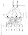
- the generation unit 130 performs machine learning using each information from the acquisition unit 110 as input data and the vehicle interior temperature and air conditioning energy consumption as output data and external input data, and obtains the air conditioning energy consumption estimation model 172 shown in FIG. Generate.
- the generation unit 130 inputs the outside air temperature, humidity, amount of solar radiation, vehicle speed, and presence / absence of a stop acquired by the acquisition unit 110, and inputs the temperature inside the vehicle (estimated temperature inside the vehicle) and the energy consumption of air conditioning (estimated energy consumption of air conditioning).
- the vehicle interior temperature estimated value estimated by the air-conditioning energy consumption estimation model 172 and the past value of the air-conditioning energy consumption are used as external inputs of the air-conditioning energy consumption estimation model 172.
- the input may be at least one of outside air temperature, humidity, amount of solar radiation, vehicle speed, and whether or not the vehicle is stopped.
- the temperature inside the vehicle does not have to be included in the external input.
- the generation unit 130 learns about a single step.
- the air-conditioning energy consumption estimation model 172 is composed of, for example, a NARX (Nonlinear Auto Regressive eXogenous) neural network model.
- the NARX neural network model is a nonlinear autoregressive time series model, which feeds back the data obtained as an output and utilizes it as an external input with autocorrelation.
- the generation unit 130 stores the generated air conditioning energy consumption estimation model 172 in the storage unit 170.
- the calculation unit 140 reads out the air-conditioning energy consumption estimation model 172 and the vehicle interior temperature and the air-conditioning energy consumption estimation value of this time cycle by the storage unit 170.
- the calculation unit 140 further reads out information on the outside air temperature, humidity, and amount of solar radiation acquired by the acquisition unit 110, and information on the vehicle speed predicted by the vehicle speed prediction unit 120 and whether or not the vehicle is stopped.
- the calculation unit 140 When estimating the air-conditioning energy consumption, the calculation unit 140 first turns on the ignition switch and then uses the past value of the air-conditioning energy consumption before the estimation start as an input to estimate the single-step air-conditioning energy consumption. Do. After that, the estimated value of air-conditioning energy consumption is fed back and the single-step estimation is repeated to perform the multi-step estimation.
- the outside air temperature, humidity, and solar radiation amount information acquired by the acquisition unit 110 are information obtained every several time cycles, and here, the latest information is read out.
- the calculation unit 140 inputs each information of the outside air temperature, humidity, the amount of solar radiation, the vehicle speed, the presence / absence of a stop, the estimated value of the temperature inside the vehicle and the estimated value of the air conditioning consumption energy of this time cycle into the air conditioning consumption energy estimation model 172, and the next time. Calculate the estimated value of the temperature inside the car and the estimated value of the air conditioning energy consumption of the cycle.
- the air-conditioning energy consumption estimation model 172 used for the vehicle interior temperature estimation value and the air-conditioning energy consumption energy estimation value is composed of a NARX neural network model, and feeds back the vehicle interior temperature estimation value and the air-conditioning energy consumption estimation value as output data. Use as input data.
- the vehicle interior temperature and the air conditioning energy consumption estimated value of the next time cycle are calculated excluding the vehicle speed of the vehicle 10 and the presence / absence of a stop. calculate.
- the calculation unit 140 stores the calculated vehicle interior temperature and air conditioning energy consumption in the next time cycle in the storage unit 170.
- the out-licensing unit 150 reads out the air-conditioning energy consumption calculated by the calculation unit 140 and the SOC of the battery 40 acquired by the acquisition unit 110 from the storage unit 170, and estimates the cruising distance of the vehicle 10.
- the out-licensing unit 150 calculates, for example, the amount of energy for calculating the cruising distance by subtracting a numerical value corresponding to the energy consumption of the air conditioner from the SOC of the battery 40.
- the out-licensing unit 150 estimates the cruising distance of the vehicle 10 based on the calculated energy amount for calculating the cruising distance.
- the derivation unit 150 stores the estimated cruising distance information of the vehicle 10 in the storage unit 170.
- the providing unit 160 outputs the information on the cruising range estimated by the out-licensing unit 150 to the display device 90 and provides it.
- the providing unit 160 outputs information on the cruising range of the vehicle 10, which is information based on the power consumption of the battery 40, to the display device 90.
- the cruising range information is provided to the user by displaying the information on the cruising range on the display unit 92 by the display device 90.
- the estimation device 100 updates the air conditioning energy consumption estimation model 172 when the ignition switch of the vehicle 10 is turned on and the switch of the air conditioning device 60 is turned on. Subsequently, the estimation device 100 derives the air conditioning consumption energy of the air conditioning device 60 by using the updated air conditioning energy consumption estimation model 172, and estimates the cruising range of the vehicle 10.
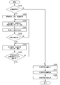
- FIG. 3 is a flowchart showing an example of the flow of processing executed by the estimation device 100.
- the estimation device 100 is activated after the ignition switch of the vehicle 10 is turned on, and as shown in FIG. 3, determines whether or not the air conditioner 60 is turned on (step S110). If it is determined that the air conditioner 60 is not ON, the process proceeds to step S200.
- the acquisition unit 110 acquires information on the SOC of the battery 40 and the vehicle speed of the vehicle 10 output by the control unit 36 (step S120).
- the acquisition unit 110 acquires information on the outside air temperature, humidity, and the amount of solar radiation as environmental conditions output by the outside air temperature sensor 82, the humidity sensor 84, and the sunshine sensor 86, respectively (step S120).
- the acquisition unit 110 acquires the vehicle interior temperature information of the vehicle 10 output by the room temperature sensor 88 and the operating condition information output by the air conditioner 60, and acquires the vehicle interior temperature of the vehicle 10 and the air conditioner 60.
- the output value of the air conditioner 60 is calculated and acquired based on the operating conditions (step S130).
- the acquisition unit 110 calculates and acquires the air conditioning energy consumption of the air conditioner 60 based on the acquired vehicle interior temperature information and the output value of the air conditioner 60 (step S130).
- the acquisition unit 110 stores the acquired vehicle interior temperature and air conditioning energy consumption information in the storage unit 170 (step S140).
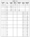
- FIG. 4 to 6 are diagrams showing an example of a data generation process created in the process of estimating the air conditioning energy consumption.
- FIG. 4 shows an example of data before the initial time elapses.
- the acquisition unit 110 acquires the vehicle interior temperature measurement value, the air conditioning output calculation value, and the air conditioning consumption energy calculation value (air conditioning consumption E calculation value), and FIG. It is stored in the storage unit 170 as the data shown in.
- the estimated device time and the actual time match.
- the vehicle interior temperature estimate and the air conditioning energy consumption estimated value air conditioning consumption E estimated value
- the measured value of the vehicle interior temperature is the vehicle interior temperature information output by the room temperature sensor 88, and the air conditioning output calculated value is based on the operating condition information output by the air conditioning device 60. It is the calculated output value of the air conditioner 60.
- the calculated air-conditioning energy consumption value is a value of the energy consumption of the air-conditioning device 60 obtained by integrating the output value of the air-conditioning device 60.
- the model input value in FIG. 2 is a predicted value obtained by a prediction device different from the estimation device 100 for estimating the outside air temperature, humidity, solar radiation, etc. based on the weather information.
- the acquisition unit 110 sets "28" for the in-vehicle room temperature measurement value item, "0” for the air conditioning output calculation value item, and air conditioning.
- the numerical value of "0” is stored in the item of the energy consumption calculation value.
- the acquisition unit 110 sets "27.99” for the in-vehicle room temperature measurement value item, "50” for the air conditioning output calculation value item, and air conditioning.
- a numerical value of "0" is added to the item of the calculated energy consumption value and stored.
- the acquisition unit 110 sets "27.98” for the room temperature measurement value in the vehicle, "100” for the air conditioning output calculation value, and air conditioning when the actual time is 2 seconds.
- a numerical value of "50” is added to the item of the calculated energy consumption value and stored.
- the estimation device 100 determines whether or not the initial time has elapsed (step S150). If it is determined that the initial time has not elapsed, the process returns to step S130, and the acquisition unit 110 repeats the processes of step S130 and step S140. When it is determined that the initial time has passed, the calculation unit 140 informs the air-conditioning energy consumption estimation model 172 stored in the storage unit 170, the environmental state, the vehicle speed, whether or not the vehicle is stopped, the temperature inside the vehicle in this time cycle, and the air-conditioning energy consumption. Is read out to estimate the vehicle interior temperature and air conditioning energy consumption in the next time cycle (step S170).
- the calculation unit 140 uses the information excluding the vehicle speed of the vehicle 10 and the presence / absence of a stop in the next time cycle. Estimate vehicle interior temperature and air conditioning energy consumption.
- FIG. 5 shows an example of data generated in the process of estimating the air conditioning energy consumption, from the time when the initial time has elapsed until the estimated value of the air conditioning display energy for the specified time is calculated.
- the specified time is 20 seconds.
- the specified time does not have to be this time, and may be a short time such as 1 minute or 5 minutes, or a long time such as 30 minutes, 1 hour or 3 hours.
- the calculation unit 140 calculates the in-vehicle room temperature estimated value and the air conditioning energy consumption estimated value for each time cycle after the initial time elapses until the specified time is reached. As shown in FIG. 5, the calculation unit 140 stores the calculated estimated value of the vehicle interior temperature and the estimated value of the air conditioning energy consumption. At this time, the measured value of the temperature inside the vehicle, the calculated value of the air conditioning output, and the calculated value of the air conditioning energy consumption are not stored. After the initial time has elapsed, the real time is much shorter than the estimated device time.
- the estimated value of the vehicle interior temperature and the estimated value of the air-conditioning energy consumption are both numerical values output by the air-conditioning energy consumption estimation model 172 shown in FIG.
- the air conditioning energy consumption estimation model 172 is calculated and stored for each time cycle.
- the calculation unit 140 when the actual time is 3 seconds and the estimation device time is "3", the item of the room temperature measurement value in the vehicle is "27.97” and the item of the air conditioning output calculation value is "150". , The number of "150” is added to the item of the air-conditioning energy consumption calculation value and stored, and the numerical value is not stored in the item of the vehicle interior temperature estimated value and the air-conditioning energy consumption energy estimated value.
- the estimation device time is "4"
- the calculation unit 140 sets "27.96” in the vehicle interior temperature estimation value item and "300” in the air conditioning energy consumption estimation value item when the actual time is 3.0001 seconds. "Is added and stored.
- the calculation unit 140 sets "27.95” in the vehicle interior temperature estimation value item and "500” in the air conditioning energy consumption estimation value item. "Is added and stored. In the same manner thereafter, the calculation unit 140 adds and stores numerical values to the items of the vehicle interior temperature estimated value and the air conditioning energy consumption estimated value at the estimation device time every time the actual time increases by 0.0001 seconds. For example, the numerical values of the items of the vehicle interior temperature estimated value and the air conditioning energy consumption estimated value at the stage of 3.005 seconds in real time are as shown in FIG.
- the calculation unit 140 determines whether or not the estimated value of air conditioning energy consumption for the specified time has been calculated (step S180). If it is determined that the estimated air-conditioning energy consumption for the specified time has not been calculated, the calculation unit 140 returns to step S170 and repeats the process of step S170.
- FIG. 6 shows an example of data obtained by calculating the estimated air-conditioning energy consumption for a specified time in the data generation process created in the process of estimating the air-conditioning energy consumption.
- the calculation unit 140 sets the estimated value of the room temperature in the vehicle and the energy consumption of the air conditioner for 17 time cycles in which the estimation device time is “4” to “20” at the stage of the actual time of 3.016 seconds.
- the estimated value is calculated, and the calculated value is added to and stored in the storage unit 170.
- the air conditioner 60 is not ON, the air conditioning energy consumption becomes zero.
- the out-licensing unit 150 estimates the cruising range of the vehicle 10 based on the SOC information of the battery 40 and the air-conditioning energy consumption information stored in the storage unit 170 (step S200).
- the cruising range is calculated as, for example, the distance at which the vehicle 10 can travel by the electric power obtained by subtracting the electric power based on the estimated value of air conditioning energy consumption in the SOC of the battery 40.
- the out-licensing unit 150 calculates the cruising distance of the vehicle 10 with the estimated air conditioning energy consumption as 0.
- the derivation unit 150 stores the estimated cruising distance information in the storage unit 170 (step S210).
- the providing unit 160 outputs the cruising range information stored in the storage unit 170 to the display device 90 (step S220). In this way, the estimation device 100 ends the process shown in FIG.
- the energy consumption of the air conditioner 60 is used when estimating the energy consumption of the battery 40 used when calculating the cruising range of the vehicle 10. Therefore, since the energy consumption of the battery 40 including the energy consumption of the air conditioner 60 can be estimated, the energy consumption of the battery 40 can be estimated more accurately.
- the energy consumption of the air conditioner 60 in the next time cycle is calculated based on the information including the energy consumption estimated value which is the feedback value of the energy consumption and the information of the environmental state. Therefore, since the calculated energy consumption of the air conditioner 60 is fed back and obtained, the energy consumption of the air conditioner 60 can be estimated more accurately.
- the air conditioning energy consumption estimation model 172 used when estimating the energy consumption of the air conditioner 60 a NARX neural network model that feeds back the data obtained as an output and uses it as an external input is used. Therefore, regarding the learning stage, the logic from data collection to learning can be simply configured, and a robust system can be constructed. Even if the logging times of the training data having different driving cycles are different, the learning can be performed without adjusting the time length between the data, and overfitting can be less likely to occur. Furthermore, since the estimation stage can be estimated at any time with the same model, it is possible to flexibly deal with the length of the estimation time.
- a neural network of the NARX neural network model particularly another neural network model that feeds back the output as an external input may be used.
- the air conditioning energy consumption may be estimated by a rule base based on each data input to the input layer of the air conditioning energy consumption estimation model 172 without using a neural network.
- FIG. 7 is an overall configuration diagram showing an example of the estimation system 1 including the estimation device 100 of the second embodiment.
- the estimation device 100 of the first embodiment is provided in the vehicle 10, but the estimation device 100 of the second embodiment is provided in, for example, an external server 400 operating on the cloud.
- the external server 400 includes an estimation device 100 and an external communication device 410.
- the external communication device 410 includes a wireless module for connecting to a cellular network or a Wi-Fi network.
- the external communication device 410 is communicably connected to the communication device 50 of the vehicle 10 via the network NW.
- the network NW includes, for example, the Internet, a WAN (Wide Area Network), a LAN (Local Area Network), a provider device, a wireless base station, and the like.
- the vehicle 10 transmits various information provided to the estimation device 100 in the first embodiment to the external server 400 by using the communication device 50.
- the external server 400 receives various information transmitted by the vehicle 10 by the external communication device 410 and outputs it to the estimation device 100.
- the estimation device 100 stores various information and the like transmitted by the vehicle 10 in the storage unit 170, estimates the cruising range information, and transmits the information to the vehicle 10 using the external communication device 410.
- the vehicle 10 receives the cruising range information transmitted by the estimation device 100 by the communication device 50 and outputs it to the display device 90.
- the display device 90 displays the output cruising range information on the display unit 92.
- the energy consumption of the battery 40 can be estimated more accurately. Since the estimation device 100 is provided on an external server outside the vehicle 10, the device mounted on the vehicle 10 can be simplified. A part of the estimation device 100 may be provided outside the vehicle 10, information may be generated by each of the estimation device 100 outside and inside the vehicle 10, and the generated information may be transmitted and received. For example, the generation unit 130 in the estimation device 100 included in the vehicle 10 in the first embodiment is omitted. The generation unit 130 may be provided in the external server 400 or the like of the second embodiment.
Landscapes
- Engineering & Computer Science (AREA)
- Power Engineering (AREA)
- Mechanical Engineering (AREA)
- Transportation (AREA)
- Life Sciences & Earth Sciences (AREA)
- Sustainable Development (AREA)
- Sustainable Energy (AREA)
- Physics & Mathematics (AREA)
- Thermal Sciences (AREA)
- Air-Conditioning For Vehicles (AREA)
- Electric Propulsion And Braking For Vehicles (AREA)
Abstract
車両の周囲の環境状態を取得する取得部と、前記車両に搭載され、ユーザの設定による稼働条件で稼働する空調装置の消費エネルギーを、前記環境状態に基づいて算出する算出部と、前記消費エネルギーに基づく情報を提供する提供部と、を備え、前記算出部は、前記消費エネルギーのフィードバック値及び前記環境状態に基づいて、次タイムサイクルの前記消費エネルギーを算出する消費エネルギー推定装置。
Description
本発明は、消費エネルギー推定装置、消費エネルギー推定方法、及びプログラムに関する。
本願は、2019年3月20日に出願された日本国特許出願2019-52844号に基づき優先権を主張し、その内容をここに援用する。
本願は、2019年3月20日に出願された日本国特許出願2019-52844号に基づき優先権を主張し、その内容をここに援用する。
走行用のモータ及びモータに電力を供給するバッテリを搭載する電動車両では、例えば航続可能距離の情報をドライバに提供する。電動車両の航続可能距離はバッテリの消費電力によって変動するため、バッテリの消費電力は、電動車両の航続可能距離を求めるための要素となる。
ところで、バッテリの電力は、電動車両に搭載される空調装置の稼働によっても消費され、空調装置が稼働すると、多くの電力が消費される。バッテリが消費した電力を検出するために、空調装置の稼働状態を考慮してバッテリの電力消費量を求める算出装置がある(例えば、特許文献1参照)。算出装置は、空調装置がON状態であるときのON時マップデータとOFF状態であるときのOFF時マップデータを備える。算出装置は、空調装置がON状態であって前回の空調装置のONよりも第1所定時間以上経過している場合に、ON時マップデータを用いて単位電力消費量あたりの航続可能距離を求める。算出装置は、空調装置がOFF状態であって前回の空調装置のOFFよりも第2所定時間以上経過している場合に、ON時マップデータを用いて単位電力消費量あたりの航続可能距離を求める。
上記特許文献1の算出装置では、空調装置のON、OFFによって単位電力消費量あたりの航続可能距離を算出するが、空調装置の負荷等に応じた稼働状態については考慮されていない。このため、上記特許文献1の算出装置では、単位電力消費量あたりの航続可能距離、さらには航続可能距離を求めるためのバッテリの消費電力を推定する精度を高める余地がある。
本発明は、このような事情を考慮してなされたものであり、より精度よくバッテリの消費電力を推定することができる消費エネルギー推定装置、消費エネルギー推定方法、及びプログラムを提供することを目的の一つとする。
この発明に係る消費エネルギー推定装置、消費エネルギー推定方法、及びプログラムは、以下の構成を採用した。
(1):この発明の一態様に係る消費エネルギー推定装置は、車両に搭載され、設定された稼働条件で稼働する空調装置の消費エネルギーを推定する消費エネルギー推定装置であって、車両の周囲の環境状態を含む情報を取得する取得部と、前タイムサイクルの前記消費エネルギーのフィードバック値及び前記取得部が取得した前記情報に基づいて、次タイムサイクルの前記消費エネルギーを算出する算出部と、を備えるものである。
(1):この発明の一態様に係る消費エネルギー推定装置は、車両に搭載され、設定された稼働条件で稼働する空調装置の消費エネルギーを推定する消費エネルギー推定装置であって、車両の周囲の環境状態を含む情報を取得する取得部と、前タイムサイクルの前記消費エネルギーのフィードバック値及び前記取得部が取得した前記情報に基づいて、次タイムサイクルの前記消費エネルギーを算出する算出部と、を備えるものである。
(2):上記(1)の態様において、前記算出部は、前タイムサイクルの前記車両の室温のフィードバック値及び前記情報に基づいて、次タイムサイクルの前記室温を更に算出するものである。
(3):上記(1)または(2)の態様において、次タイムサイクルの前記車両の走行状態を予測する予測部を更に備え、前記算出部は、前記予測部が予測した前記走行状態に更に基づいて、次タイムサイクルの前記消費エネルギーを算出するものである。
(4):上記(3)の態様において、前記算出部は、前記予測部が所定条件を満たさない場合に、前記走行状態に更に基づく次タイムサイクルの前記消費エネルギーの算出を禁止するものである。
(5):上記(1)から(4)のいずれかの態様において、前タイムサイクルの前記消費エネルギーのフィードバック値及び前記情報を入力データとし、次タイムサイクルの前記消費エネルギーを出力データとするモデルを生成する生成部を更に備え、前記算出部は、前記生成部が生成した前記モデルを用いて次タイムサイクルの前記消費エネルギーを算出するものである。
(6):上記(5)の態様において、前記生成部は、機械学習により前記モデルを生成するものである。
(7):上記(1)から(6)のいずれかの態様において、前記算出部が算出した前記消費エネルギーに基づく情報を提供する提供部を更に備えるものである。
(8):上記(1)から(7)のいずれかの態様において、前記環境状態は、前記車両の周囲の湿度、外気温、及び日射量のうち少なくとも1つである。
(9):上記(1)から(8)のいずれかの態様において、前記車両は、バッテリにより走行用の電力の供給を受ける電動車両である。
(10):この発明の他の態様に係る消費エネルギー推定方法は、車両に搭載され、設定された稼働条件で稼働する空調装置の消費エネルギーを推定する消費エネルギー推定装置が、車両の周囲の環境状態を含む情報を取得し、前タイムサイクルの前記消費エネルギーのフィードバック値及び取得した前記情報に基づいて、次タイムサイクルの前記消費エネルギーを算出するものである。
(11):この発明の他の態様に係るプログラムは、車両に搭載され、設定された稼働条件で稼働する空調装置の消費エネルギーを推定する消費エネルギー推定装置に、車両の周囲の環境状態を含む情報を取得させ、前タイムサイクルの前記消費エネルギーのフィードバック値及び取得した前記情報に基づいて、次タイムサイクルの前記消費エネルギーを算出させるものである。
(1)~(11)によれば、より精度よくバッテリの消費電力を推定することができる。
以下、図面を参照し、本発明の消費エネルギー推定装置、消費エネルギー推定方法、及びプログラムの実施形態について説明する。以下の説明において、車両10は電動車両(電気自動車)であるものとするが、車両10は、走行用の電力を供給する二次電池を搭載した車両であればよく、ハイブリッド自動車や燃料電池車両であってもよい。以下の明細書において、消費エネルギー推定装置を推定装置といい、消費エネルギー推定システムを推定システムということがある。
<第1実施形態>
本発明の第1実施形態について説明する。
本発明の第1実施形態について説明する。
[車両10]
図1は、推定装置100を含む車両10の構成の一例を示す図である。図1に示すように、車両10は、例えば、モータ12と、駆動輪14と、ブレーキ装置16と、車両センサ20と、PCU(Power Control Unit)30と、バッテリ40と、電圧センサ、電流センサ、温度センサなどのバッテリセンサ42と、通信装置50と、空調装置60と、充電口70と、コンバータ72と、外気温センサ82と、湿度センサ84と、日照センサ86と、室温センサ88と、表示装置90と、推定装置100と、を備える。
図1は、推定装置100を含む車両10の構成の一例を示す図である。図1に示すように、車両10は、例えば、モータ12と、駆動輪14と、ブレーキ装置16と、車両センサ20と、PCU(Power Control Unit)30と、バッテリ40と、電圧センサ、電流センサ、温度センサなどのバッテリセンサ42と、通信装置50と、空調装置60と、充電口70と、コンバータ72と、外気温センサ82と、湿度センサ84と、日照センサ86と、室温センサ88と、表示装置90と、推定装置100と、を備える。
モータ12は、例えば、三相交流電動機である。モータ12のロータは、駆動輪14に連結される。モータ12は、供給される電力を用いて動力を駆動輪14に出力する。モータ12は、車両の減速時に車両の運動エネルギーを用いて発電する。
ブレーキ装置16は、例えば、ブレーキキャリパーと、ブレーキキャリパーに油圧を伝達するシリンダと、シリンダに油圧を発生させる電動モータと、を備える。ブレーキ装置16は、ブレーキペダルの操作によって発生した油圧を、マスターシリンダを介してシリンダに伝達する機構をバックアップとして備えてよい。ブレーキ装置16は、上記説明した構成に限らず、マスターシリンダの油圧をシリンダに伝達する電子制御式油圧ブレーキ装置であってもよい。
車両センサ20は、アクセル開度センサと、車速センサと、ブレーキ踏量センサと、を備える。アクセル開度センサは、アクセルペダルに取り付けられ、アクセルペダルの操作量を検出し、アクセル開度として制御部36に出力する。車速センサは、例えば、各車輪に取り付けられた車輪速センサと速度計算機とを備え、車輪速センサにより検出された車輪速を統合して車両の速度(車速)を導出し、制御部36に出力する。ブレーキ踏量センサは、ブレーキペダルに取り付けられ、ブレーキペダルの操作量を検出し、ブレーキ踏量として制御部36に出力する。
PCU30は、例えば、変換器32と、VCU(Voltage Control Unit)34と、制御部36と、を備える。これらの構成要素をPCU34として一まとまりの構成としたのは、あくまで一例であり、これらの構成要素は分散的に配置されても構わない。
変換器32は、例えば、AC-DC変換器である。変換器32の直流側端子は、直流リンクDLに接続されている。直流リンクDLには、VCU34を介してバッテリ40が接続されている。変換器32は、モータ12により発電された交流を直流に変換して直流リンクDLに出力する。
VCU34は、例えば、DC―DCコンバータである。VCU34は、バッテリ40から供給される電力を昇圧して直流リンクDLに出力する。
制御部36は、例えば、モータ制御部と、ブレーキ制御部と、バッテリ・VCU制御部と、を備える。モータ制御部、ブレーキ制御部、及びバッテリ・VCU制御部は、それぞれ別体の制御装置、例えば、モータECU、ブレーキECU、バッテリECUといった制御装置に置き換えられてもよい。
制御部36は、モータ制御部において、車両センサ20の出力に基づいて、モータ12を制御する。制御部36は、ブレーキ制御部において、車両センサ20の出力に基づいて、ブレーキ装置16を制御する。制御部36は、バッテリ・VCU制御部において、バッテリ40に取り付けられたバッテリセンサ42の出力に基づいて、バッテリ40のSOC(State Of Charge;以下「バッテリ充電率」ともいう)を算出し、VCU34及び推定装置100に出力する。制御部36は、車両センサ20により車速が出力された車速の情報を推定装置100に出力する。VCU34は、バッテリ・VCU制御からの指示に応じて、直流リンクDLの電圧を上昇させる。
バッテリ40は、例えば、リチウムイオン電池などの二次電池である。バッテリ40には、車両10の外部の充電器200から導入される電力を蓄え、車両10の走行のための放電を行う。バッテリセンサ42は、例えば、電流センサ、電圧センサ、温度センサを備える。バッテリセンサ42は、例えば、バッテリ40の電流値、電圧値、温度を検出する。バッテリセンサ42は、検出した電流値、電圧値、温度等を制御部36に出力する。
通信装置50は、セルラー網やWi-Fi網を接続するための無線モジュールを含む。通信装置50は、不図示の気象情報サーバ等と通信し、気象情報サーバにより提供される気象情報等を受信して取得する。気象情報には、例えば、外気温、湿度、日射量などの情報が含まれる。通信装置50は、取得した気象情報を推定装置100に出力する。
空調装置60は、車両10に搭載され、車室内の空気の状態を調整することにより、車室内の環境を調整する。空調装置60は、ユーザの操作による設定を受け付けたエアコンECUによって制御される。エアコンECUは、ユーザの設定による稼働条件で空調装置60を制御する。例えば、空調装置60をONする操作がユーザによりなされると、エアコンECUは、空調装置60を起動させ、空調装置60をOFFする操作がユーザによりなされると、エアコンECUは、空調装置60を停止させる。
空調装置60は、設定温度、設定風量、稼働時間等の稼働条件を設定可能とされている。例えば、空調装置60の設定温度は「高」「中」「低」の3段階に調整可能とされ、稼働時間は「長」「中」「短」の3段階に調整可能とされ、設定風量は「強」「中」「弱」の3段階に調整可能とされている。例えば、ユーザにより空調装置60の設定温度が「低」とする操作がなされると、エアコンECUは、空調装置60の設定温度を「低」に調整する。これらの調整段階は3段階以外の段階でもよい。設定温度「28℃」等、稼働条件を具体的にしてできるようにしてもよい。
空調装置60の消費エネルギーは、空調装置60の設定温度が低いほど大きくなる。空調装置60の消費エネルギーは、空調装置60の設定風量が大きいほど大きくなる。空調装置60の消費エネルギーは、稼働時間が長いほど、大きくなる。空調装置60の消費エネルギーとは、空調装置60の稼働によるバッテリ40の消費エネルギー(消費電力)である。空調装置60のエアコンECUは、空調装置60のON-OFFの情報、及び稼働条件の情報を推定装置100に出力する。空調装置60は、例えば、空調装置60がONまたはOFFされた場合にON-OFFの情報を推定装置100に出力し、空調装置60がONされた場合または稼働条件が変更された場合に、稼働条件の情報を推定装置100に出力する。
充電口70は、車両10の車体外部に向けて設けられている。充電口70は、充電ケーブル220を介して充電器200に接続される。充電ケーブル220は、第1プラグ222と第2プラグ224を備える。第1プラグ222は、充電器200に接続され、第2プラグ224は、充電口70に接続される。充電器200から供給される電気は、充電ケーブル220を介して充電口70に供給される。
充電ケーブル220は、電力ケーブルに付設された信号ケーブルを含む。信号ケーブルは、車両10と充電器200の間の通信を仲介する。したがって、第1プラグ222と第2プラグ224のそれぞれには、電力ケーブルを接続する電力コネクタと信号ケーブルを接続する信号コネクタが設けられている。
コンバータ72は、充電口70とバッテリ40の間に設けられる。コンバータ72は、充電口70を介して充電器200から導入される電流、例えば交流電流を、バッテリ40に供給するための電流、例えば直流電流に変換する。コンバータ72は、変換した直流電流をバッテリ40に対して出力する。
外気温センサ82及び湿度センサ84は、例えば、エンジン、車体、路面の熱の影響を受けにくい箇所、例えば、フロントバンパー付近に設置される。外気温センサ82は、車両10の外気温を測定する。外気温センサ82は、測定した外気温の情報を推定装置100に出力する。湿度センサ84は、車両10の外の湿度を測定する。湿度センサ84は、検出した湿度の情報を推定装置100に出力する。
日照センサ86は、車両10のインストルメントパネルあるいはフロントウインドシールド等に設置され、車両10の周囲の日射量を測定する。日照センサ86は、測定した日射量の情報を推定装置100に出力する。室温センサ88は、例えば、インストルメントパネルの下部内側に装着され、車両10の車内温度(室温)を測定する。室温センサ88は、測定した車内温度の情報を推定装置100に出力する。
外気温センサ82、湿度センサ84、日照センサ86、及び室温センサ88は、所定時間間隔ごとにそれぞれの情報を出力する。ここでの所定時間は、どのような時間でもよく、例えば、1秒でもよいし、10秒でもよいし、1分や1時間でもよい。実施形態では、所定時間は1秒である。外気温センサ82、湿度センサ84、日照センサ86、及び室温センサ88は同じ時間、同じ時間間隔で各情報を出力してもよいし、異なる時間、異なる時間間隔で各情報を出力してもよい。
表示装置90は、表示部92と、表示制御部94と、を備える。表示部92は、表示制御部94の制御に応じた情報を表示する。表示制御部94は、推定装置100により出力される情報、例えば航続可能距離の情報を表示部92に表示させる。航続可能距離とは、バッテリ40の電力によって車両10が走行可能となる距離をいう。表示装置90は、バッテリ40の消費電力に基づく情報は、車両10の航続可能距離以外の情報、例えばバッテリ40の劣化状態などの情報であってもよい。表示装置90と推定装置100を合わせて推定表示システムと称してもよい。
推定装置100は、取得部110と、車速予測部120と、生成部130と、算出部140と、導出部150と、提供部160と、記憶部170と、を備える。取得部110、車速予測部120、生成部130、算出部140、導出部150、及び提供部160は、例えば、CPU(Central Processing Unit)などのハードウェアプロセッサがプログラム(ソフトウェア)を実行することにより実現される。これらの構成要素のうち一部または全部は、LSI(Large Scale Integration)やASIC(Application Specific Integrated Circuit)、FPGA(Field-Programmable Gate Array)、GPU(Graphics Processing Unit)などのハードウェア(回路部;circuitryを含む)によって実現されてもよいし、ソフトウェアとハードウェアの協働によって実現されてもよい。プログラムは、予めHDD(Hard Disk Drive)やフラッシュメモリなどの記憶装置(非一過性記憶媒体)に格納されていてもよいし、DVDやCD-ROMなどの着脱可能な記憶媒体(非一過性記憶媒体)に格納されており、記憶媒体がドライブ装置に装着されることでインストールされてもよい。記憶部170は、前述した記憶装置により実現される。
推定装置100は、車両の周囲の環境状態及びユーザの設定による空調装置60の稼働条件に基づいて、空調装置60の消費エネルギーを導出し、導出した消費エネルギー及びバッテリ40のSOCに基づいて、車両10の航続可能距離を推定してユーザに提示する。推定装置100は、空調装置60の消費エネルギーを1タイムサイクルごとの数値として導出する。1タイムサイクルは任意の時間間隔でよく、例えば、0.1m秒等の比較的短い時間間隔でもよいし、1秒等の比較的長い時間間隔でもよい。
1タイムサイクルは、外気温センサ82、湿度センサ84、日照センサ86、及び室温センサ88が各情報を出力する所定時間と同じでもよいし、短くてもよいし長くてもよい。実施形態における1タイムサイクルは、0.1m秒である。実施形態では、1タイムサイクルは、所定時間より長くされている。
取得部110は、制御部36により出力される情報、例えばバッテリ40のSOC及び車両10の車速の情報を取得する。取得部110は、空調装置60により出力される情報、例えば空調装置60のON-OFFや稼働条件の情報を取得する。取得部110は、外気温センサ82、湿度センサ84、日照センサ86、及び室温センサ88によりそれぞれ出力される外気温、湿度、日射量、及び車内温度の各情報を取得する。外気温、湿度、及び日射量は、本発明の「環境状態」の一例である。取得部110は、外気温センサ82、湿度センサ84、日照センサ86、及び室温センサ88によりそれぞれ出力される外気温、湿度、日射量に代えてまたは加えて、気象サーバにより提供される気象情報に含まれる外気温、湿度、日射量などの情報を取得してもよい。取得部110は、外気温センサ82、湿度センサ84、日照センサ86、及び室温センサ88によりそれぞれ出力される外気温、湿度、日射量を、気象サーバにより提供される気象情報に基づいて補正してもよい。
取得部110は、空調装置60により出力される稼働条件の情報に基づいて、空調装置60の出力値を算出して取得する。推定装置100は、例えば、1タイムサイクルよりも長い間隔を空けて環境状態の情報を取得する。このため、取得部110は、外気温等の情報を数タイムサイクルごとに取得する。取得部110は、取得した各種の情報を記憶部170に格納する。
取得部110は、車室内温度及び稼働条件の情報に基づいて、空調装置60が稼働を開始した直後の数秒間(以下「初期時間」という)における空調装置60の消費エネルギー(以下「空調消費エネルギー」という)を算出する。取得部110は、空調装置60により出力された稼働条件に基づいて、空調装置60の出力を算出する。取得部110は、室温センサ88により出力された車内温度及び算出した空調消費エネルギーの情報を記憶部170に格納する。空調装置60が稼働を開始した直後の初期時間は、どのような時間に設定してもよく、例えば、1秒、10秒、30秒などとしてもよい。実施形態における初期時間は3秒である。
車速予測部120は、制御部36により出力された車速の情報に基づいて、次タイムサイクルの車両10の車速を予測する。車速予測部120は、例えば、制御部36により出力された所定時間内における過去数回分の車速情報を記憶部170に格納し、過去数回分の車速情報に基づいて次タイムサイクルの車両10の車速を予測する。
車速予測部120は、所定条件を満たす場合、例えば、所定時間内における過去数回分の車速情報が揃う場合に、次タイムサイクルの車両10の車速を予測し、所定時間内における過去数回分の車速情報が揃わない場合には、次タイムサイクルの車両10の車速の予測を禁止して、車速を予測しない。車速予測部120は、次タイムサイクルの車両10の車速を予測する際に、車両10の停車の有無も合わせて予測する。車速予測部120は、予測した次タイムサイクルの車両10の車速及び停車の有無の情報を記憶部170に格納する。車両10の車速及び停車の有無は、走行状態の一例である。
生成部130は、取得部110により取得された各情報を用いて空調消費エネルギーを推定するための空調消費エネルギー推定モデルを生成する。生成部130は、取得部110によりの各情報を入力データとするとともに、車内温度及び空調消費エネルギーを出力データ及び外部入力データとした機械学習を行い、図2に示す空調消費エネルギー推定モデル172を生成する。
例えば、生成部130は、取得部110により取得された外気温、湿度、日射量、車速、停車の有無を入力とし、車内温度(車内温度推定値)及び空調消費エネルギー(空調消費エネルギー推定値)を出力とするニューラルネットワークモデルからなる空調消費エネルギー推定モデル172を生成する。さらに、空調消費エネルギー推定モデル172により推定された車内温度推定値及び空調消費エネルギーの過去値が、空調消費エネルギー推定モデル172の外部入力となる。入力は、外気温、湿度、日射量、車速、停車の有無のうち少なくとも1つでもよい。車内温度は、外部入力に含まれなくてもよい。生成部130は、シングルステップについて学習を行う。
空調消費エネルギー推定モデル172は、例えば、NARX(Nonlinear Auto Regressive eXogenous)ニューラルネットワークモデルからなる。NARXニューラルネットワークモデルは、非線形自己回帰型の時系列モデルであり、出力として得たデータをフィードバックして、外部入力として自己相関をもって活かすモデルである。生成部130は、生成した空調消費エネルギー推定モデル172を記憶部170に格納する。
算出部140は、記憶部170により空調消費エネルギー推定モデル172及び今回タイムサイクルの車内温度と空調消費エネルギー推定値を読み出す。算出部140は、更に、取得部110により取得した外気温、湿度、日射量の各情報、及び車速予測部120により予測した車速、停車の有無の情報を読み出す。
算出部140は、空調消費エネルギーを推定する際、最初は、イグニッションスイッチをONにした後、推定開始前の空調消費エネルギーの過去値を入力に使用して、シングルステップの空調消費エネルギーの推定を行う。その後、空調消費エネルギー推定値をフィードバックして、シングルステップの推定を繰り返すことで、マルチステップの推定を行う。
取得部110により取得した外気温、湿度、日射量の各情報は、数タイムサイクルごとに得られた情報であり、ここでは、最も新しい情報を読み出す。算出部140は、外気温、湿度、日射量、車速、停車の有無、今回タイムサイクルの車内温度推定値及び空調消費エネルギー推定値の各情報を空調消費エネルギー推定モデル172に入力して、次タイムサイクルの車内温度推定値及び空調消費エネルギー推定値を算出する。このように、車内温度推定値及び空調消費エネルギー推定値に用いられる空調消費エネルギー推定モデル172は、NARXニューラルネットワークモデルからなり、出力データとなる車内温度推定値及び空調消費エネルギー推定値をフィードバックして入力データとして利用する。
車速予測部120により今回タイムサイクルの車両10の車速及び停車の有無が予測されていない場合には、車両10の車速及び停車の有無を除いて次タイムサイクルの車内温度及び空調消費エネルギー推定値を算出する。算出部140は、算出した次タイムサイクルの車内温度及び空調消費エネルギーを記憶部170に格納する。
導出部150は、算出部140で算出した空調消費エネルギー及び取得部110で取得したバッテリ40のSOC等を記憶部170から読み出し、車両10の航続可能距離を推定する。導出部150は、例えば、バッテリ40のSOCから空調消費エネルギーに応じた数値を減じて、航続可能距離算出用エネルギー量を算出する。導出部150は、算出した航続可能距離算出用エネルギー量に基づいて、車両10の航続可能距離を推定する。導出部150は、推定した車両10の航続可能距離の情報を記憶部170に格納する。
提供部160は、導出部150により推定された航続可能距離の情報を、表示装置90に出力して提供する。提供部160は、バッテリ40の消費電力に基づく情報である車両10の航続可能距離の情報を表示装置90に出力する。航続可能距離の情報は、表示装置90が表示部92に表示することにより、ユーザに提供される。
次に、推定装置100における処理の一例について説明する。推定装置100は、車両10のイグニッションスイッチをONにし、空調装置60のスイッチをONにしたときに空調消費エネルギー推定モデル172を更新する。続いて、推定装置100は、更新した空調消費エネルギー推定モデル172を用いて、空調装置60の空調消費エネルギーを導出し、車両10の航続可能距離を推定する。
図3は、推定装置100において実行される処理の流れの一例を示すフローチャートである。推定装置100は、車両10のイグニッションスイッチがONとなった後に起動し、図3に示すように、空調装置60がONであるか否かを判定する(ステップS110)。空調装置60がONでないと判定した場合、ステップS200に進む。
空調装置60がONであると判定した場合、取得部110は、制御部36により出力されるバッテリ40のSOC及び車両10の車速の情報を取得する(ステップS120)。取得部110は、外気温センサ82、湿度センサ84、及び日照センサ86によりそれぞれ出力される環境状態としての外気温、湿度、及び日射量の各情報を取得する(ステップS120)。続いて、取得部110は、室温センサ88により出力される車両10の車内温度の情報及び空調装置60により出力される稼働条件の情報を取得し、取得した車両10の車内温度及び空調装置60の稼働条件に基づいて、空調装置60の出力値を算出して取得する(ステップS130)。取得部110は、取得した車内温度の情報及び空調装置60の出力値に基づいて、空調装置60の空調消費エネルギーを算出して取得する(ステップS130)。取得部110は、取得した車内温度及び空調消費エネルギーの情報を記憶部170に格納する(ステップS140)。
図4から図6は、空調消費エネルギーを推定する工程で作成されるデータの生成工程の一例を示す図である。図4には、初期時間が経過する前のデータの一例を示す。空調消費エネルギーを推定するにあたり、初期時間が経過する前は、取得部110が、車内温度測定値、空調出力算出値、空調消費エネルギー算出値(空調消費E算出値)を取得して、図4に示すデータとして記憶部170に格納する。初期時間が経過する前は、推定装置時刻と実時間が一致している。初期時間が経過する前は、車内温度推定値や空調消費エネルギー推定値(空調消費E推定値)は格納されない。
図4に示される数値のうち、車内温度の測定値は、室温センサ88により出力される車内温度の情報であり、空調出力算出値は、空調装置60により出力された稼働条件の情報に基づいて算出された空調装置60の出力値である。空調消費エネルギー算出値は、空調装置60の出力値を積分して得られる空調装置60の消費エネルギーの値である。図2におけるモデル入力値は、気象情報に基づく外気温、湿度、日射量等の推定装置100とは異なる予測装置によって得られる予測値である。
例えば、取得部110は、実時間が0秒の段階では、推定装置時刻が「0」のときに、車内室温測定値の項目に「28」、空調出力算出値の項目に「0」、空調消費エネルギー算出値の項目に「0」の数値を格納する。取得部110は、実時間が1秒の段階では、推定装置時刻が「1」のときに、車内室温測定値の項目に「27.99」、空調出力算出値の項目に「50」、空調消費エネルギー算出値の項目に「0」の数値を追加して格納する。取得部110は、実時間が2秒の段階では、推定装置時刻が「2」のときに、車内室温測定値の項目に「27.98」、空調出力算出値の項目に「100」、空調消費エネルギー算出値の項目に「50」の数値を追加して格納する。
続いて、推定装置100は、初期時間が経過したか否かを判定する(ステップS150)。初期時間が経過していないと判定した場合、ステップS130に戻り、取得部110は、ステップS130及びステップS140の処理を繰り返す。初期時間が経過したと判定した場合、算出部140は、記憶部170に格納された空調消費エネルギー推定モデル172及び環境状態、車速、停車の有無、今回タイムサイクルの車内温度、空調消費エネルギーの情報を読み出し、次タイムサイクルの車内温度及び空調消費エネルギーを推定する(ステップS170)。車速予測部120により今回タイムサイクルの車両10の車速及び停車の有無が予測されていない場合には、算出部140は、車両10の車速及び停車の有無を除いた情報を用いて次タイムサイクルの車内温度及び空調消費エネルギーを推定する。
図5には、空調消費エネルギーを推定する工程で作成されるデータの生成工程のうち、初期時間が経過した後、規定時間分の空調表示エネルギー推定値を算出するまでのデータの一例を示す。実施形態では、規定時間を20秒としている。規定時間は、この時間でなくてもよく、例えば、1分、5分、といった短時間であってもよいし、30分、1時間、3時間等の長時間であってもよい。
算出部140は、初期時間が経過した後、規定時間となるまでの間は、1タイムサイクルごとに車内室温推定値及び空調消費エネルギー推定値を算出する。算出部140は、図5に示すように、算出した車内温度の推定値及び空調消費エネルギー推定値を格納する。このとき、車内温度の測定値、空調出力算出値、空調消費エネルギー算出値を格納しない状態となっている。初期時間が経過した後は、実時間は、推定装置時刻よりも非常に短くなっている。車内温度の推定値及び空調消費エネルギー推定値は、いずれも図2に示す空調消費エネルギー推定モデル172により出力された数値である。空調消費エネルギー推定モデル172は、1タイムサイクルごとに算出されて格納される。
例えば、算出部140は、実時間が3秒の段階では、推定装置時刻が「3」のときに、車内室温測定値の項目に「27.97」、空調出力算出値の項目に「150」、空調消費エネルギー算出値の項目に「150」の数を追加して格納し、車内温度の推定値及び空調消費エネルギー推定値の項目には数値を格納しない。算出部140は、実時間が3.0001秒の段階では、推定装置時刻が「4」のときに、車内温度推定値の項目に「27.96」、空調消費エネルギー推定値の項目に「300」の数値を追加して格納する。
算出部140は、実時間が3.0002秒の段階では、推定装置時刻が「5」のときに、車内温度推定値の項目に「27.95」、空調消費エネルギー推定値の項目に「500」の数値を追加して格納する。算出部140は、以後同様にして、実時間が0.0001秒増加するごとに推定装置時刻における車内温度推定値及び空調消費エネルギー推定値の項目に数値を追加して格納する。例えば、実時間3.0005秒の段階での車内温度推定値及び空調消費エネルギー推定値の項目の数値は、図5に示すようになる。
続いて、算出部140は、規定時間分の空調消費エネルギー推定値を算出したか否かを判定する(ステップS180)。規定時間分の空調消費エネルギー推定値を算出していないと判定した場合、算出部140は、ステップS170に戻り、ステップS170の処理を繰り返す。
図6には、空調消費エネルギーを推定する工程で作成されるデータの生成工程のうち、規定時間分の空調消費エネルギー推定値を算出したデータの一例を示す。例えば、図6に示すように、算出部140は、実時間が3.0016秒の段階では、推定装置時刻が「4」~「20」の17タイムサイクルについて、車内室温推定値及び空調消費エネルギー推定値を算出し、算出した数値を記憶部170に追加して格納している。空調装置60がONでない場合には、空調消費エネルギーは0となる。
続いて、導出部150は、記憶部170に格納されたバッテリ40のSOCの情報及び空調消費エネルギーの情報に基づいて車両10の航続可能距離を推定する(ステップS200)。航続可能距離は、例えば、バッテリ40のSOCのうち、空調消費エネルギー推定値に基づく電力を減じた電力によって車両10が走行可能となる距離として算出される。ステップS110において空調装置がONでないと判定された場合には、導出部150は、空調消費エネルギー推定値を0として車両10の航続可能距離を算出する。導出部150は、推定した航続可能距離の情報を記憶部170に格納する(ステップS210)。続いて、提供部160は、記憶部170に格納された航続可能距離の情報を表示装置90に出力する(ステップS220)。こうして、推定装置100は、図3に示す処理を終了する。
上記の第1実施形態によれば、車両10の航続可能距離を算出する際に用いるバッテリ40の消費エネルギーを推定する際に、空調装置60の消費エネルギーを用いている。このため、空調装置60消費エネルギーを加味したバッテリ40の消費エネルギーを推定できるので、より精度よくバッテリ40の消費エネルギーを推定することができる。空調装置60の消費エネルギーを推定する際に、消費エネルギーのフィードバック値である消費エネルギー推定値及び環境状態の情報を含む情報に基づいて、次タイムサイクルの空調装置60の消費エネルギーを算出する。このため、算出した空調装置60の消費エネルギーをフィードバックして求めるので、より精度よく空調装置60の消費エネルギーを推定することができる。
空調装置60の消費エネルギーを推定する際に用いる空調消費エネルギー推定モデル172として、出力として得たデータをフィードバックして、外部入力とするNARXニューラルネットワークモデルを用いている。このため、学習段階に関して、データの収集から学習までのロジックをシンプルに構成することができ、ロバストなシステムを構築することができる。ドライビングサイクルの異なる学習データのロギング時間が異なっていても、データ間時間長を合わせることなく学習を行うことができるとともに、過学習を起こしにくくすることができる。さらに、推定段階に関しては、同じモデルで任意の時間で推定ができるので、推定時間の長さに関して柔軟に対応することができる。
空調消費エネルギー推定モデルとしては、NARXニューラルネットワークモデルのニューラルネットワーク、特に出力を外部入力としてフィードバックする他のニューラルネットワークモデルを用いてもよい。ニューラルネットワークを用いることなく、空調消費エネルギー推定モデル172の入力層に入力された各データに基づくルールベースによって空調消費エネルギーを推定してもよい。
<第2実施形態>
次に、本発明の第2実施形態について説明する。
次に、本発明の第2実施形態について説明する。
図7は、第2実施形態の推定装置100を含む推定システム1の一例を示す全体構成図である。第1実施形態の推定装置100は、車両10に備えられていたが、第2実施形態の推定装置100は、例えばクラウド上で動作する外部サーバ400に設けられている。外部サーバ400は、推定装置100と、外部通信装置410と、を備える。
外部通信装置410は、セルラー網やWi-Fi網に接続するための無線モジュールを含む。外部通信装置410は、ネットワークNWを介して車両10の通信装置50と通信可能に接続されている。ネットワークNWは、例えば、インターネット、WAN(Wide Area Network)、LAN(Local Area Network)、プロバイダ装置、無線基地局などを含む。
車両10は、第1実施形態において推定装置100に提供する各種情報を、通信装置50を用いて、外部サーバ400に送信する。外部サーバ400は、車両10により送信された各種の情報を、外部通信装置410によって受信し、推定装置100に出力する。
推定装置100は、車両10により送信された各種の情報等を記憶部170に格納するとともに、航続可能距離の情報を推定し、外部通信装置410を用いて車両10に送信する。車両10は、推定装置100により送信される航続可能距離の情報を通信装置50によって受信し、表示装置90に出力する。表示装置90は、出力された航続可能距離の情報を表示部92に表示する。
上記の第2実施形態によれば、より精度よくバッテリ40の消費エネルギーを推定することができる。推定装置100が、車両10の外部における外部サーバに設けられているので、車両10に搭載される装置を簡素なものとすることができる。推定装置100の一部を車両10の外部に設け、車両10の外部と内部の推定装置100のそれぞれにおいて情報を生成して、生成した情報を送受信するようにしてもよい。例えば、第1実施形態における車両10が備える推定装置100における生成部130を省略し。生成部130を第2実施形態の外部サーバ400等に設けるようにしてもよい。
以上、本発明を実施するための形態について実施形態を用いて説明したが、本発明はこうした実施形態に何等限定されるものではなく、本発明の要旨を逸脱しない範囲内において種々の変形及び置換を加えることができる。
1…推定システム
10…車両
12…モータ
20…車両センサ
36…制御部
40…バッテリ
42…バッテリセンサ
50…通信装置
60…空調装置
70…充電口
82…外気温センサ
84…湿度センサ
86…日照センサ
88…室温センサ
90…表示装置
92…表示部
94…表示制御部
100…推定装置
110…取得部
120…車速予測部
130…生成部
140…算出部
150…導出部
160…提供部
170…記憶部
172…空調消費エネルギー推定モデル
10…車両
12…モータ
20…車両センサ
36…制御部
40…バッテリ
42…バッテリセンサ
50…通信装置
60…空調装置
70…充電口
82…外気温センサ
84…湿度センサ
86…日照センサ
88…室温センサ
90…表示装置
92…表示部
94…表示制御部
100…推定装置
110…取得部
120…車速予測部
130…生成部
140…算出部
150…導出部
160…提供部
170…記憶部
172…空調消費エネルギー推定モデル
Claims (11)
- 車両に搭載され、設定された稼働条件で稼働する空調装置の消費エネルギーを推定する消費エネルギー推定装置であって、
車両の周囲の環境状態を含む情報を取得する取得部と、
前タイムサイクルの前記消費エネルギーのフィードバック値及び前記取得部が取得した前記情報に基づいて、次タイムサイクルの前記消費エネルギーを算出する算出部と、を備える、
消費エネルギー推定装置。 - 前記算出部は、前タイムサイクルの前記車両の室温のフィードバック値及び前記情報に基づいて、次タイムサイクルの前記室温を更に算出する、
請求項1に記載の消費エネルギー推定装置。 - 次タイムサイクルの前記車両の走行状態を予測する予測部を更に備え、
前記算出部は、前記予測部が予測した前記走行状態に更に基づいて、次タイムサイクルの前記消費エネルギーを算出する、
請求項1または2に記載の消費エネルギー推定装置。 - 前記算出部は、前記予測部が所定条件を満たさない場合に、前記走行状態に更に基づく次タイムサイクルの前記消費エネルギーの算出を禁止する、
請求項3に記載の消費エネルギー推定装置。 - 前タイムサイクルの前記消費エネルギーのフィードバック値及び前記情報を入力データとし、次タイムサイクルの前記消費エネルギーを出力データとするモデルを生成する生成部を更に備え、
前記算出部は、前記生成部が生成した前記モデルを用いて次タイムサイクルの前記消費エネルギーを算出する、
請求項1から4のうちいずれか1項に記載の消費エネルギー推定装置。 - 前記生成部は、機械学習により前記モデルを生成する、
請求項5に記載の消費エネルギー推定装置。 - 前記算出部が算出した前記消費エネルギーに基づく情報を提供する提供部を更に備える、
請求項1から6のうちいずれか1項に記載の消費エネルギー推定装置。 - 前記環境状態は、前記車両の周囲の湿度、外気温、及び日射量のうち少なくとも1つである、
請求項1から7のうちいずれか1項に記載の消費エネルギー推定装置。 - 前記車両は、バッテリにより走行用の電力の供給を受ける電動車両である、
請求項1から8のうちいずれか1項に記載の消費エネルギー推定装置。 - 車両に搭載され、設定された稼働条件で稼働する空調装置の消費エネルギーを推定する消費エネルギー推定装置が、
車両の周囲の環境状態を含む情報を取得し、
前タイムサイクルの前記消費エネルギーのフィードバック値及び取得した前記情報に基づいて、次タイムサイクルの前記消費エネルギーを算出する、
消費エネルギー推定方法。 - 車両に搭載され、設定された稼働条件で稼働する空調装置の消費エネルギーを推定する消費エネルギー推定装置に、
車両の周囲の環境状態を含む情報を取得させ、
前タイムサイクルの前記消費エネルギーのフィードバック値及び取得した前記情報に基づいて、次タイムサイクルの前記消費エネルギーを算出させる、
プログラム。
Priority Applications (1)
| Application Number | Priority Date | Filing Date | Title |
|---|---|---|---|
| JP2021507425A JP7471274B2 (ja) | 2019-03-20 | 2020-03-19 | 消費エネルギー推定装置、消費エネルギー推定方法、及びプログラム |
Applications Claiming Priority (2)
| Application Number | Priority Date | Filing Date | Title |
|---|---|---|---|
| JP2019052844 | 2019-03-20 | ||
| JP2019-052844 | 2019-03-20 |
Publications (1)
| Publication Number | Publication Date |
|---|---|
| WO2020189771A1 true WO2020189771A1 (ja) | 2020-09-24 |
Family
ID=72520302
Family Applications (1)
| Application Number | Title | Priority Date | Filing Date |
|---|---|---|---|
| PCT/JP2020/012418 Ceased WO2020189771A1 (ja) | 2019-03-20 | 2020-03-19 | 消費エネルギー推定装置、消費エネルギー推定方法、及びプログラム |
Country Status (2)
| Country | Link |
|---|---|
| JP (1) | JP7471274B2 (ja) |
| WO (1) | WO2020189771A1 (ja) |
Cited By (6)
| Publication number | Priority date | Publication date | Assignee | Title |
|---|---|---|---|---|
| CN114005195A (zh) * | 2021-11-17 | 2022-02-01 | 中国第一汽车股份有限公司 | 一种续驶里程的显示方法、装置、车辆及存储介质 |
| CN115195396A (zh) * | 2022-06-24 | 2022-10-18 | 珠海格力电器股份有限公司 | 一种驻车空调节能控制方法 |
| JP2023030978A (ja) * | 2021-08-24 | 2023-03-08 | スズキ株式会社 | 車室内温度の表示制御装置 |
| CN116587810A (zh) * | 2023-04-03 | 2023-08-15 | 四川欣智造科技有限公司 | 一种热交换方法和热交换系统 |
| CN117162792A (zh) * | 2023-09-04 | 2023-12-05 | 浙江智马达智能科技有限公司 | 一种车辆的空调能耗预测方法及空调能耗预测系统 |
| JP2024077364A (ja) * | 2022-11-28 | 2024-06-07 | トヨタ自動車株式会社 | 車両の制御装置 |
Citations (2)
| Publication number | Priority date | Publication date | Assignee | Title |
|---|---|---|---|---|
| WO2014162526A1 (ja) * | 2013-04-02 | 2014-10-09 | パイオニア株式会社 | 消費エネルギー量推定装置、消費エネルギー量推定方法、消費エネルギー量推定プログラムおよび記録媒体 |
| US20170038222A1 (en) * | 2014-08-29 | 2017-02-09 | Ford Global Technologies, Llc | Route-Based Distance to Empty Calculation For A Vehicle |
Family Cites Families (3)
| Publication number | Priority date | Publication date | Assignee | Title |
|---|---|---|---|---|
| JP3584571B2 (ja) * | 1995-10-19 | 2004-11-04 | 日産自動車株式会社 | 電気自動車用事前空調装置 |
| JP2004297854A (ja) * | 2003-03-25 | 2004-10-21 | Hitachi Information & Control Systems Inc | デマンド監視システム |
| JP2014054124A (ja) * | 2012-09-10 | 2014-03-20 | Suzuki Motor Corp | 電動車両の航続可能距離算出装置 |
-
2020
- 2020-03-19 WO PCT/JP2020/012418 patent/WO2020189771A1/ja not_active Ceased
- 2020-03-19 JP JP2021507425A patent/JP7471274B2/ja active Active
Patent Citations (2)
| Publication number | Priority date | Publication date | Assignee | Title |
|---|---|---|---|---|
| WO2014162526A1 (ja) * | 2013-04-02 | 2014-10-09 | パイオニア株式会社 | 消費エネルギー量推定装置、消費エネルギー量推定方法、消費エネルギー量推定プログラムおよび記録媒体 |
| US20170038222A1 (en) * | 2014-08-29 | 2017-02-09 | Ford Global Technologies, Llc | Route-Based Distance to Empty Calculation For A Vehicle |
Cited By (9)
| Publication number | Priority date | Publication date | Assignee | Title |
|---|---|---|---|---|
| JP2023030978A (ja) * | 2021-08-24 | 2023-03-08 | スズキ株式会社 | 車室内温度の表示制御装置 |
| JP7627430B2 (ja) | 2021-08-24 | 2025-02-06 | スズキ株式会社 | 車室内温度の送信装置および通信端末 |
| CN114005195A (zh) * | 2021-11-17 | 2022-02-01 | 中国第一汽车股份有限公司 | 一种续驶里程的显示方法、装置、车辆及存储介质 |
| CN114005195B (zh) * | 2021-11-17 | 2024-03-26 | 中国第一汽车股份有限公司 | 一种续驶里程的显示方法、装置、车辆及存储介质 |
| CN115195396A (zh) * | 2022-06-24 | 2022-10-18 | 珠海格力电器股份有限公司 | 一种驻车空调节能控制方法 |
| JP2024077364A (ja) * | 2022-11-28 | 2024-06-07 | トヨタ自動車株式会社 | 車両の制御装置 |
| JP7798010B2 (ja) | 2022-11-28 | 2026-01-14 | トヨタ自動車株式会社 | 車両の制御装置 |
| CN116587810A (zh) * | 2023-04-03 | 2023-08-15 | 四川欣智造科技有限公司 | 一种热交换方法和热交换系统 |
| CN117162792A (zh) * | 2023-09-04 | 2023-12-05 | 浙江智马达智能科技有限公司 | 一种车辆的空调能耗预测方法及空调能耗预测系统 |
Also Published As
| Publication number | Publication date |
|---|---|
| JP7471274B2 (ja) | 2024-04-19 |
| JPWO2020189771A1 (ja) | 2020-09-24 |
Similar Documents
| Publication | Publication Date | Title |
|---|---|---|
| JP7471274B2 (ja) | 消費エネルギー推定装置、消費エネルギー推定方法、及びプログラム | |
| US11267316B2 (en) | Air conditioning control device, air conditioning control method, and program | |
| US11043043B2 (en) | Dynamic driving range prediction for electric vehicles | |
| CN110549876B (zh) | 一种能量输出控制方法、装置和氢燃料混合动力汽车 | |
| JP5372561B2 (ja) | 電気自動車の制御装置 | |
| US20210146785A1 (en) | Driver model estimation, classification, and adaptation for range prediction | |
| US20210291698A1 (en) | Diagnostic device, diagnostic method, and program | |
| US11364813B2 (en) | Battery state determination system, battery state determination method, and recording medium | |
| US20140121956A1 (en) | System and method for range calculation in vehicles | |
| US9020671B2 (en) | Vehicle control using an estimated outside air temperature | |
| JP6713030B2 (ja) | 診断システム、診断方法、及びプログラム | |
| US20140188304A1 (en) | Optimal electric vehicle battery recommendation system | |
| US9539998B2 (en) | System and method for improved control, response and energy management of a vehicle | |
| US20210323419A1 (en) | Vehicle, server device, display control method, and program | |
| EP2940780A2 (en) | Battery management apparatus | |
| KR20140095780A (ko) | 전기 자동차의 주행 가능 거리를 예측하기 위한 장치 및 그 방법 | |
| US20200298724A1 (en) | Intelligent soc reset system for autonomous vehicle | |
| CN112534671B (zh) | 提示装置、提示方法以及存储介质 | |
| JP6100595B2 (ja) | 航続可能距離算出装置 | |
| AU2024263431A1 (en) | Battery thermal management method and apparatus, electronic device, and storage medium | |
| CN102700426A (zh) | 电动汽车的行驶控制系统及行驶控制方法 | |
| JP2016173957A (ja) | 二次電池冷却システム | |
| CN106553550A (zh) | 电动汽车的剩余里程估算方法、系统及电动汽车 | |
| KR20180065741A (ko) | 고성능 네트워크 차량의 vcu를 이용한 연산 시스템 및 방법 | |
| KR20140083555A (ko) | 전기 자동차의 주행 가능 거리를 예측하기 위한 장치 및 그 방법 |
Legal Events
| Date | Code | Title | Description |
|---|---|---|---|
| 121 | Ep: the epo has been informed by wipo that ep was designated in this application |
Ref document number: 20774241 Country of ref document: EP Kind code of ref document: A1 |
|
| ENP | Entry into the national phase |
Ref document number: 2021507425 Country of ref document: JP Kind code of ref document: A |
|
| NENP | Non-entry into the national phase |
Ref country code: DE |
|
| 122 | Ep: pct application non-entry in european phase |
Ref document number: 20774241 Country of ref document: EP Kind code of ref document: A1 |