WO2020189691A1 - 入力デバイス - Google Patents
入力デバイス Download PDFInfo
- Publication number
- WO2020189691A1 WO2020189691A1 PCT/JP2020/011828 JP2020011828W WO2020189691A1 WO 2020189691 A1 WO2020189691 A1 WO 2020189691A1 JP 2020011828 W JP2020011828 W JP 2020011828W WO 2020189691 A1 WO2020189691 A1 WO 2020189691A1
- Authority
- WO
- WIPO (PCT)
- Prior art keywords
- light
- light emitting
- input device
- tracked
- shielding
- Prior art date
- Legal status (The legal status is an assumption and is not a legal conclusion. Google has not performed a legal analysis and makes no representation as to the accuracy of the status listed.)
- Ceased
Links
Images


Classifications
-
- G—PHYSICS
- G06—COMPUTING OR CALCULATING; COUNTING
- G06F—ELECTRIC DIGITAL DATA PROCESSING
- G06F3/00—Input arrangements for transferring data to be processed into a form capable of being handled by the computer; Output arrangements for transferring data from processing unit to output unit, e.g. interface arrangements
- G06F3/01—Input arrangements or combined input and output arrangements for interaction between user and computer
- G06F3/03—Arrangements for converting the position or the displacement of a member into a coded form
- G06F3/0304—Detection arrangements using opto-electronic means
-
- G—PHYSICS
- G06—COMPUTING OR CALCULATING; COUNTING
- G06F—ELECTRIC DIGITAL DATA PROCESSING
- G06F3/00—Input arrangements for transferring data to be processed into a form capable of being handled by the computer; Output arrangements for transferring data from processing unit to output unit, e.g. interface arrangements
- G06F3/01—Input arrangements or combined input and output arrangements for interaction between user and computer
- G06F3/011—Arrangements for interaction with the human body, e.g. for user immersion in virtual reality
- G06F3/014—Hand-worn input/output arrangements, e.g. data gloves
-
- G—PHYSICS
- G06—COMPUTING OR CALCULATING; COUNTING
- G06F—ELECTRIC DIGITAL DATA PROCESSING
- G06F3/00—Input arrangements for transferring data to be processed into a form capable of being handled by the computer; Output arrangements for transferring data from processing unit to output unit, e.g. interface arrangements
- G06F3/01—Input arrangements or combined input and output arrangements for interaction between user and computer
- G06F3/03—Arrangements for converting the position or the displacement of a member into a coded form
- G06F3/033—Pointing devices displaced or positioned by the user, e.g. mice, trackballs, pens or joysticks; Accessories therefor
- G06F3/0346—Pointing devices displaced or positioned by the user, e.g. mice, trackballs, pens or joysticks; Accessories therefor with detection of the device orientation or free movement in a three-dimensional [3D] space, e.g. 3D mice, 6-DOF [six degrees of freedom] pointers using gyroscopes, accelerometers or tilt-sensors
Definitions
- the present disclosure relates to an input device having a tracked portion.
- Japanese Unexamined Patent Publication No. 2011-164932 discloses an input device for game operation provided with a spherical light emitting unit.
- the input device proposed in the present disclosure has a grip, a plurality of light emitting parts, and a tracked part extending in one direction.
- the tracked portion is provided with a first light emitting portion and has a first outer surface extending in the extending direction of the tracked portion and a second outer surface provided with a second light emitting portion and extending in the extending direction of the tracked portion. And a light-shielding part.
- the first outer surface and the second outer surface are arranged in a direction orthogonal to the extending direction of the tracked portion.
- the first outer surface faces the first direction.
- the second outer surface faces a second direction different from the first direction.
- the light-shielding portion is located outside the first light emitting portion and the second light emitting portion. According to this structure, it is possible to prevent the two light emitting parts from overlapping in the image obtained through the camera.
- the directions indicated by Z1 and Z2 in FIG. 2 are referred to as upward and downward, respectively, the directions indicated by X1 and X2 in FIG. 2 are referred to as right and left, respectively, and the directions indicated by Y1 and Y2 in FIG. Are referred to as anterior and posterior, respectively. These directions correspond to the directions seen by the user when the user holds and uses the input device 100 as shown in FIG.
- the input device 100 is used, for example, with a head-mounted display (HMD) 2.
- the user wears the HMD2 on his head and holds the input device 100 in his right and / or left hand.
- the HMD2 has a camera facing forward.
- the input device 100 is provided with a plurality of light emitting units H, which will be described later.
- the position of the light emitting unit H is detected through the camera, and the position and posture of the input device 100 (that is, the position and orientation of the user's hand) are calculated based on the position of the light emitting unit.
- the input device 100 has a plurality of operation units (for example, operation buttons, operation sticks, touch sensors, etc.) that the user operates with a finger.
- a moving image (for example, a game image) generated based on the position of the input device 100, its posture, an operation performed on the operation unit, or the like is displayed on the display unit of the HMD2.
- the calculation of the position and orientation of the input device 100 may be executed by an information processing device mounted on the HMD2, or by an external information processing device (for example, a game device separate from the HMD2 or a personal computer). May be done.
- the input device 100 may have a motion sensor (for example, an acceleration sensor or a gyro sensor).
- the information processing device may calculate the position and orientation of the input device 100 based not only on the position of the light emitting unit H but also on the output of the motion sensor. Further, the generation of the moving image may also be executed by the information processing device mounted on the HMD2, or may be executed by an external information processing device.
- the image information acquired by the camera of the HMD2 is transmitted to the external information processing device wirelessly or by wire.
- the moving image information generated by the external information processing device is transmitted to the HMD2 wirelessly or by wire.
- the input device 100 may be used separately from the HMD2.
- the camera for tracking the position and orientation of the input device 100 does not necessarily have to be provided in the HMD2, and may be arranged at a position distant from the user in front.
- the camera may be attached to an external display device (eg, a television or personal computer monitor) that displays a moving image generated based on the position or orientation of the input device 100.
- the outer shape of the right-hand input device 100 and the outer shape of the left-hand input device 100 may be symmetrical.
- the input device 100 for the right hand will be described in detail.
- the main body 10 of the input device 100 has a grip 11B and an operation area 11A in which a plurality of operation units are arranged.
- the main body 10 has an operation area 11A in the upper part thereof, and the grip 11B extends downward from the operation area 11A.
- the operation unit arranged in the operation area 11A can be operated by the thumb or the index finger while holding the grip 11B.
- the grip 11B is held by, for example, the thumb ball, the middle finger, the ring finger, and the little finger.
- the operation buttons 13, 14, 15 and the operation stick 16 are arranged as operation units in the operation area 11A.
- the operation button 13 is arranged on the front surface 11a of the operation area 11A (see FIG. 3), and is operated by, for example, the index finger.
- the operation buttons 14 and 15 and the operation stick 16 are arranged on the back surface 11b of the operation area 11A (see FIG. 2) and are operated by, for example, the thumb.
- the operation stick 16 is an operation unit that can be tilted or slid in the radial direction.
- the operation unit provided in the operation area 11A is not limited to the example described here.
- a touch sensor, a trigger button, and a button with a touch sensor may be provided in the operation area 11A.
- the number of operation units provided in the operation area 11A may be one, two, or four or more.
- the input device 100 has a tracked unit 30 in which a plurality of light emitting units H are arranged (the light emitting unit is indicated by a black circle in the figure).
- the tracked portion 30 is located on the right side of the main body 10 and is connected to the uppermost portion of the main body 10 and the lowermost portion of the main body 10.
- the tracked portion 30 extends downward from the uppermost portion of the main body 10 while being curved so as to bulge outward in the left-right direction.
- the position and shape of the tracked unit 30 are not limited to the examples shown in the figure as long as the light emitting unit H can be stably detected by the camera mounted on the HMD2.
- the tracked portion 30 may be located to the left of the main body 10 or may be located above, below, behind, or in front of the main body 10.
- the shape of the tracked portion 30 may be not a curved rod shape but a straight rod shape or an annular shape.
- the tracked portion 30 may be arranged so as to surround the hand or wrist of the user holding the grip 11B.
- the main body 10 may also be provided with a light emitting unit H.
- a plurality of light emitting units H may be provided on the front surface 11a or the back surface 11b of the operation area 11A, or a plurality of light emitting units H may be provided on the lower portion 11e of the grip 11B as shown in FIG.
- the tracked portion 30 has an exterior member 31 constituting the outer surface A of the tracked portion 30, and a plurality of light sources S arranged inside the exterior member 31.
- the light source S for example, a light emitting diode (LED) can be used.
- the light source S is arranged along the exterior member 31 inside, for example, the exterior member 31. In this case, the positions of the plurality of light sources S correspond to the positions of the light emitting unit H, respectively.
- the light source S is mounted on, for example, a flexible substrate (FPC) supported by a frame (not shown).
- the exterior member 31 is made of, for example, an opaque material.
- the exterior member 31 itself may be formed of an opaque material, or the surface of the exterior member 31 may be coated with a light-impermeable material.
- the exterior member 31 is made of an opaque material, only the position of the light emitting portion H in the exterior member 31 is formed of a material that allows light to pass through. A hole through which light passes may be formed at the position of the light emitting portion H on the exterior member 31.
- the outer surface A includes a first outer surface A1 and a second outer surface A2.
- the two outer surfaces A1 and A2 extend in the stretching direction of the tracked portion 30, and are arranged in a direction orthogonal to the stretching direction.
- the tracked portion 30 is curved so as to extend in the vertical direction and bulge to the right (see FIG. 2). Therefore, the two outer surfaces A1 and A2 are curved so as to extend in the vertical direction and bulge to the right as shown in FIG.
- the outer surfaces A1 and A2 are formed adjacent to each other in the front-rear direction and are connected to each other.
- the outer surface A is gently curved from the first outer surface A1 to the second outer surface A2.
- the outer surface A may be bent between the two outer surfaces A1 and A2 and have an angle between them.
- a plurality of light emitting portions H are provided on each of the two outer surfaces A1 and A2.
- the plurality of light emitting portions H are arranged in the extending direction of the tracked portion 30.
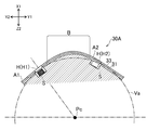
- the direction in which the first outer surface A1 faces (the direction of the normal line D1 shown in FIG. 5) and the direction in which the second outer surface A2 faces (the direction of the normal line D2 shown in FIG. 5) are different.
- the outer surface A1 faces backward and right, and the outer surface A2 faces forward and right.
- X1, Y1, and Y2 represent the right, front, and rear of the input device 100, respectively).
- a light-shielding portion B is provided in the tracked portion 30.
- the light-shielding portion B is a part of the exterior member 31, and is located between the light-emitting portion H1 on the first outer surface A1 and the light-emitting portion H2 on the second outer surface A2.
- the light emitting units H1 and H2 are the two light emitting parts H on the first outer surface A1 and the plurality of light emitting parts H on the second outer surface A2, which are the shortest distances.
- It is a portion located outside the two light emitting portions H1 and H2.
- the light-shielding portion B is a portion located outside the straight line L3 connecting the two light-emitting portions H1 and H2.
- the light-shielding portion B is located to the right of the straight line L3. According to such a light-shielding unit B, it is possible to prevent the two light-emitting units H1 and H2 from overlapping in the image acquired by the camera.
- the distance D from the top Ap of the light-shielding portion B to the line L3 may be larger than the diameter R1 of the light-emitting portion H.
- the distance D from the top Ap of the light-shielding portion B to the line L3 may be larger than 1.5 times the diameter R1 of the light-emitting portion H.
- the light-shielding portion B is a virtual contact with the first outer surface A1 and the second outer surface A2 when viewed in a cross section obtained by a plane orthogonal to the stretching direction of the tracked portion 30. It is desirable to include a portion located outside the arc Va.
- the arc Va is, for example, an arc that is in contact with the first outer surface A1 and in contact with the second outer surface A2 at the position of the light emitting portion H1 of the first outer surface A1.
- the arc Va is, for example, an arc that is in contact with the first outer surface A1 at the position of the light emitting portion H1 of the first outer surface A1 and is in contact with the virtual plane including the second outer surface A2.
- the arc Va is a part of a perfect circle having a center Pc.
- the distance N1 from the top Ap of the outer surface A to the light emitting unit H1 is larger than the distance N2 from the top Ap of the outer surface A to the light emitting unit H2.
- the above-mentioned arc Va is an arc defined by the light emitting unit H1 having the larger distance among the two light emitting units H1 and H2.
- the light-shielding portion B extends in the stretching direction of the tracked portion 30. It is desirable that the light-shielding portion B is formed over the entire region where the light-emitting portion H of the tracked portion 30 is provided.
- the position of the light-shielding portion B is not limited to the example of the input device 100.
- the light-shielding portion B may be formed intermittently, for example, in the stretching direction of the tracked portion 30.
- two light emitting parts H first light emitting part H of the first outer surface A1 and a light emitting part H of the second outer surface A2 are formed with a light emitting part B, but the distance is large.
- the light-shielding portion B may not be formed between another light-emitting portion H on the outer surface A1 and another light-emitting portion H on the second outer surface A2).
- the "outer surface A” is a surface composed of the outermost member of the tracked portion 30, and is composed of an opaque exterior member and a transparent exterior member.
- the "light emitting portion H” is a portion of the exterior member through which light passes. For example, as shown in FIGS. 4 and 5, in a structure in which the exterior member 31 is made of an opaque material and a light-transmitting material or a hole is formed at the position of the light source S, the light-transmitting material is formed.
- the light emitting portion H is the portion where the light is formed or the portion where the hole for passing light is formed.
- the structure see FIG.
- FIG. 8 a structure described later in which a transparent exterior member is arranged on the outermost surface of the tracked portion 30, a light guide member is arranged inside the exterior member, and the light of the light source S is guided by the light guide member (FIG. 8).
- the portion of the light guide member facing the end surface (light emitting surface) is the light emitting portion H.
- the direction of the optical axis of the light emitting unit H is substantially the same as the direction in which the outer surfaces A1 and A2 are facing.
- the light-shielding portion B is formed, for example, as a part of an opaque exterior member 31. According to this structure, the light-shielding portion B can be secured without increasing the number of parts.
- a part of the outer surface A including the boundary between the first outer surface A1 and the second outer surface A2 functions as the light shielding portion B. More specifically, a ridge line (in other words, a corner portion) between the first outer surface A1 and the second outer surface A2 connected to the first outer surface A1 is formed, and this ridge line functions as a light-shielding portion B.
- the exterior member 31 has a rib (wall portion) integrally formed with the exterior member 31 between the first outer surface A1 and the second outer surface A2. ), And this rib may function as a light-shielding portion B.
- the light-shielding portion B may be a member formed separately from the exterior member 31.
- the light-shielding portion B may be formed of a material such as sponge, silicone, rubber, or plastic separately from the exterior member 31, and may be attached to the exterior member 31 or the frame of the tracked portion 30.
- the first outer surface A1 is located behind the second outer surface A2. Therefore, when the user holds the input device 100, the first outer surface A1 becomes a surface closer to the camera than the second outer surface A2, that is, a surface closer to the user's body. Therefore, the first outer surface A1 is more likely to be displayed in the image acquired by the camera than the second outer surface A2. As shown in FIG. 5, when the cross section orthogonal to the stretching direction of the tracked portion 30 is viewed, the width W1 of the first outer surface A1 is larger than the width W2 of the second outer surface A2.
- the width W1 of the first outer surface A1 closer to the camera is larger than the width W2 of the second outer surface A2 farther from the camera.
- the degree of freedom regarding the position and number of the light emitting portions H provided on the first outer surface A1 can be increased.
- N1 is larger than the distance N2 from the top Ap to the light emitting portion H2.
- the top Ap is the portion having the largest curvature on the outer surface A of the tracked portion 30 when the cross section of the tracked portion 30 is viewed.
- This relationship of distance is provided on the first outer surface A1.
- the other light emitting unit H and the other light emitting unit H provided on the second outer surface A2 may also be established.
- the background formed around the light emitting portion H1 on the first outer surface A1 becomes large.
- the light emitting unit H1 can be easily recognized correctly through the camera, and the tracking accuracy can be improved.
- the light emitting portion H is located in the range W3 of the width W1 in the front-rear direction of the first outer surface A1 from the rear end Ae of the first outer surface A1 to the range W3 of 2/3 of the width W1. In other words, it is desirable that the light emitting portion H is located in the range W3 of 2/3 of the width W1 from the end portion Ae in the direction toward the camera. It is more desirable that the light emitting portion H is located in a range of 1/2 of the width W1 from the end portion Ae in the direction toward the camera.
- the first outer surface A1 is provided with a plurality of light emitting portions H arranged in the stretching direction of the tracked portion 30, and the second outer surface A2 is also provided with a plurality of light emitting portions H arranged in the same stretching direction.
- a second light emitting unit H is provided. Therefore, the tracking accuracy can be improved.
- the number of light emitting units H provided on the first outer surface A1 is larger than the number of light emitting units H on the second outer surface A2. That is, the number of light emitting units H that are easily displayed in the image acquired by the camera is large.
- the position of the light emitting portion H on the first outer surface A1 and the position of the light emitting portion H on the second outer surface A2 are the extending directions of the tracked portion 30 (up and down in the example of the input device 100). (Direction) is out of alignment. Therefore, a sufficient distance is secured between the light emitting unit H on the first outer surface A1 and the light emitting unit H on the second outer surface A2, and as a result, the light emitting unit H on the first outer surface A1 and the camera are connected.
- the angle ⁇ between the straight line L1 and the straight line L2 connecting the light emitting portion H on the second outer surface A2 and the camera can be sufficiently secured.
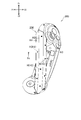
- the light-shielding portion B may be made of a member different from the exterior member 31. 7 to 9 are views for explaining a modified example of the tracked portion 30. In these figures, the same reference numerals as those described above are attached.
- the tracked portion 30A has a frame 33 that is arranged inside the exterior member 31 and supports the light source S.
- the light source S may be mounted on a substrate (not shown), and this substrate may be attached to the frame 33.
- the exterior member 31 is made of a transparent material.
- a part of the frame 33 may be the light-shielding portion B.
- This light-shielding portion B is also located outside the virtual arc Va. According to this structure, the frame 33 supporting the light source S can function as the light-shielding portion B, so that an increase in the number of parts can be suppressed.
- the tracked portion 30B has a substrate 34 and light guide members 35a and 35b arranged along the stretching direction of the tracked portion 30B.
- the light source S is mounted on both sides of the substrate 34 (first substrate surface 34a and second substrate surface 34b).
- the substrate 34 is, for example, a rigid substrate.
- the substrate 34 is arranged so that the first substrate surface 34a faces the first outer surface A1 and the second substrate surface 34b faces the second outer surface A2.
- the light of the light source S mounted on the first substrate surface 34a is guided by the light guide member 35a to the light emitting portion H1 on the first outer surface A1, and the light of the light source S mounted on the second substrate surface 34a is guided.
- the light member 35b guides the light source H2 on the second outer surface A2.
- the exterior member 31 is made of a transparent material. In this structure, a part of the substrate 34 may function as a light-shielding portion B. The light-shielding portion B is also located outside the virtual arc Va.
- the substrate 34 is arranged along the top Ap of the outer surface A. That is, the position of the substrate 34 in the front-rear direction coincides with the position of the top Ap. However, the substrate 34 may be displaced rearward (Y2 direction) from the position of the top Ap as shown by the alternate long and short dash line in the figure, or may be displaced forward (Y1 direction).
- the tracked portion 30C has a substrate 134 arranged along the extending direction of the tracked portion 30C, light guide members 135a and 135b, and a wall member 136.
- the light source S is mounted only on one substrate surface 134a of the substrate 134.
- the substrate 134 is arranged so that the substrate surface 134a faces the first outer surface A1 and the second outer surface A2.
- the light of the two light sources S mounted on the substrate surface 134a is guided by the light guide members 135a and 135b to the light emitting unit H1 on the first outer surface A1 and the light emitting unit H2 on the second outer surface A2, respectively.
- the exterior member 31 is made of a transparent or light-transmitting material.
- the wall member 136 is arranged so as to stand with respect to the substrate 134, and a part of the wall member 136 functions as a light-shielding portion B.
- the light-shielding portion B is also located outside the virtual arc Va.
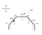
- the tracked portion 230 is arranged on the left side of the main body 210.
- the tracked portion 230 has a first outer surface A1, a second outer surface A2, and a third outer surface A3 extending in the extending direction of the tracked portion 230.
- the three outer surfaces A1, A2, and A3 are arranged in a direction orthogonal to the stretching direction of the tracked portion 230 (in the example of the input device 200, the front-rear direction).
- Light emitting portions H are provided on the outer surfaces A1, A2, and A3.
- the light-shielding portion B1 is located between the light-emitting portion H1 on the first outer surface A1 and the light-emitting portion H2 on the second outer surface A2.
- the light-shielding portion B2 is located between the light-emitting portion H2 on the second outer surface A2 and the light-emitting portion H3 on the third outer surface A3.
- the light-shielding portion B1 includes a portion located outside the two light-emitting portions H1 and H2, and the light-shielding portion B2 includes a portion located outside the two light-emitting portions H2 and H3.
- the relationship between the light emitting portions H1 and H2, the outer surfaces A1 and A2, and the light shielding portion B1 shown in FIG. 10C is the same as the relationship between the light emitting portions H1 and H2 and the light emitting portion B described with reference to FIG. You can.
- the relationship between the light emitting portions H2 / H3, the outer surfaces A2 / A3, and the light shielding portion B2 shown in FIG. 10C may be the same as the relationship between the light emitting portions H1 / H2 and the light shielding portion B described with reference to FIG. .. That is, it is desirable that the light-shielding portion B1 includes a portion located outside the virtual arc Va in contact with the first outer surface A1 and the second outer surface A2.
- the light-shielding portion B2 also includes a portion located outside the virtual arc Va in contact with the second outer surface A2 and the third outer surface A3. (The arc in contact with the two outer surfaces A1 and A2 and the arc in contact with the two outer surfaces A2 and A3 do not have to be the same.)
- the above is the description of the input device 200 shown in FIGS. 10A to 10C.
- the shape of the tracked portion 30 may be annular.
- the two outer surfaces A1 and A2 extend in the circumferential direction and are aligned in a direction perpendicular to the circumferential direction (direction along the center line of the annular tracked portion 30). Then, a light-shielding portion B that also extends in the circumferential direction is formed between the two adjacent outer surfaces A1 and A2.
- the light-shielding portion B was formed over the entire region where the light-emitting portion H of the tracked portion 30 was provided.
- the light-shielding portion B may be provided only between one light-emitting portion H on the first outer surface A1 and one light-emitting portion H provided on the second outer surface A2.
- the input device 100 does not have to have an operation unit operated by a finger, such as operation buttons 13, 14, 15, and an operation stick 16. Even in this case, the user may be able to reflect the movement in the moving image displayed on the HMD2 by moving the input device 100 while holding the grip 11B.
- the camera for tracking the position and orientation of the input device 100 does not necessarily have to be provided in the HMD2, and may be arranged at a position distant from the user in front.
- the camera may be attached to an external display device (eg, a television or personal computer monitor) that displays a moving image generated based on the position or orientation of the input device 100.
- the type of camera for tracking the position and orientation of the input device 100 is not particularly limited.
- the camera may have an image sensor that detects visible light, or may be an infrared image sensor. Further, the camera may be equipped with a sensor (Dynamic vision sensor, Event Driven Sensor, etc.) that outputs only the information of the pixel that has changed in the entire angle of view.
- a sensor Dynamic vision sensor, Event Driven Sensor, etc.
Landscapes
- Engineering & Computer Science (AREA)
- General Engineering & Computer Science (AREA)
- Theoretical Computer Science (AREA)
- Human Computer Interaction (AREA)
- Physics & Mathematics (AREA)
- General Physics & Mathematics (AREA)
- Position Input By Displaying (AREA)
- User Interface Of Digital Computer (AREA)
- Studio Devices (AREA)
- Stroboscope Apparatuses (AREA)
- Image Input (AREA)
Priority Applications (7)
| Application Number | Priority Date | Filing Date | Title |
|---|---|---|---|
| CN202080019738.6A CN113544628B (zh) | 2019-03-18 | 2020-03-17 | 输入装置 |
| CN202411024729.2A CN119088209A (zh) | 2019-03-18 | 2020-03-17 | 输入装置 |
| US17/436,232 US12602104B2 (en) | 2019-03-18 | 2020-03-17 | Input device |
| EP20774631.4A EP3944059A4 (en) | 2019-03-18 | 2020-03-17 | INPUT DEVICE |
| JP2021507381A JP7328322B2 (ja) | 2019-03-18 | 2020-03-17 | 入力デバイス |
| JP2023127005A JP7568799B2 (ja) | 2019-03-18 | 2023-08-03 | 入力デバイス |
| US18/787,253 US20240385680A1 (en) | 2019-03-18 | 2024-07-29 | Input Device |
Applications Claiming Priority (2)
| Application Number | Priority Date | Filing Date | Title |
|---|---|---|---|
| JP2019050278 | 2019-03-18 | ||
| JP2019-050278 | 2019-03-18 |
Related Child Applications (2)
| Application Number | Title | Priority Date | Filing Date |
|---|---|---|---|
| US17/436,232 A-371-Of-International US12602104B2 (en) | 2019-03-18 | 2020-03-17 | Input device |
| US18/787,253 Continuation US20240385680A1 (en) | 2019-03-18 | 2024-07-29 | Input Device |
Publications (1)
| Publication Number | Publication Date |
|---|---|
| WO2020189691A1 true WO2020189691A1 (ja) | 2020-09-24 |
Family
ID=72520162
Family Applications (1)
| Application Number | Title | Priority Date | Filing Date |
|---|---|---|---|
| PCT/JP2020/011828 Ceased WO2020189691A1 (ja) | 2019-03-18 | 2020-03-17 | 入力デバイス |
Country Status (5)
| Country | Link |
|---|---|
| US (2) | US12602104B2 (https=) |
| EP (1) | EP3944059A4 (https=) |
| JP (2) | JP7328322B2 (https=) |
| CN (2) | CN119088209A (https=) |
| WO (1) | WO2020189691A1 (https=) |
Cited By (1)
| Publication number | Priority date | Publication date | Assignee | Title |
|---|---|---|---|---|
| JP2023181132A (ja) * | 2022-06-10 | 2023-12-21 | 株式会社ソニー・インタラクティブエンタテインメント | Ir及び周囲光(または深度センサ)を使用したハイブリッド画素による動的視覚センサの追跡 |
Families Citing this family (4)
| Publication number | Priority date | Publication date | Assignee | Title |
|---|---|---|---|---|
| US12059609B2 (en) | 2022-06-10 | 2024-08-13 | Sony Interactive Entertainment Inc. | Asynchronous dynamic vision sensor LED AI tracking system and method |
| US11995226B2 (en) | 2022-06-10 | 2024-05-28 | Sony Interactive Entertainment Inc. | Dynamic vision sensor tracking based on light source occlusion |
| US12210674B2 (en) | 2022-06-10 | 2025-01-28 | Sony Interactive Entertainment Inc. | Dynamic vision sensor based eye and/or facial tracking |
| US12064682B2 (en) | 2022-06-10 | 2024-08-20 | Sony Interactive Entertainment Inc. | Deployment of dynamic vision sensor hybrid element in method for tracking a controller and simultaneous body tracking, slam or safety shutter |
Citations (3)
| Publication number | Priority date | Publication date | Assignee | Title |
|---|---|---|---|---|
| JP2011164932A (ja) | 2010-02-09 | 2011-08-25 | Sony Computer Entertainment Inc | 操作デバイス |
| WO2017213818A1 (en) * | 2016-06-11 | 2017-12-14 | Sony Interactive Entertainment Inc. | Directional interface object |
| JP2018106258A (ja) * | 2016-12-22 | 2018-07-05 | 株式会社コロプラ | 仮想空間を提供するための方法、および当該方法をコンピュータに実行させるためのプログラム、および当該プログラムを実行するための情報処理装置 |
Family Cites Families (17)
| Publication number | Priority date | Publication date | Assignee | Title |
|---|---|---|---|---|
| CN101213774B (zh) | 2005-07-01 | 2012-01-04 | 希尔克瑞斯特实验室公司 | 3d定位装置 |
| US20070080940A1 (en) * | 2005-10-07 | 2007-04-12 | Sharp Kabushiki Kaisha | Remote control system, and display device and electronic device using the remote control system |
| US8344325B2 (en) * | 2009-05-22 | 2013-01-01 | Motorola Mobility Llc | Electronic device with sensing assembly and method for detecting basic gestures |
| EP2634670A1 (en) | 2012-03-01 | 2013-09-04 | Asplund Data AB | A data input device |
| KR102138510B1 (ko) * | 2013-08-27 | 2020-07-28 | 엘지전자 주식회사 | 근접 터치 기능을 구비한 전자 장치 및 그 제어 방법 |
| EP3193238A4 (en) | 2014-09-10 | 2018-07-18 | Sony Corporation | Detection device, detection method, control device, and control method |
| US9898091B2 (en) * | 2015-06-03 | 2018-02-20 | Oculus Vr, Llc | Virtual reality system with head-mounted display, camera and hand-held controllers |
| US9983709B2 (en) | 2015-11-02 | 2018-05-29 | Oculus Vr, Llc | Eye tracking using structured light |
| US10007339B2 (en) * | 2015-11-05 | 2018-06-26 | Oculus Vr, Llc | Controllers with asymmetric tracking patterns |
| US9977494B2 (en) * | 2015-12-30 | 2018-05-22 | Oculus Vr, Llc | Tracking constellation assembly for use in a virtual reality system |
| JP6881896B2 (ja) | 2016-04-20 | 2021-06-02 | キヤノン株式会社 | 頭部装着装置および把持装置 |
| JP6731787B2 (ja) | 2016-06-02 | 2020-07-29 | 株式会社Subaru | 繊維強化複合材料の製造方法及び穿孔・接合装置 |
| CN205899500U (zh) | 2016-07-27 | 2017-01-18 | 上海拆名晃信息科技有限公司 | 用于实现人机交互的手柄 |
| US10549183B2 (en) * | 2016-10-11 | 2020-02-04 | Valve Corporation | Electronic controller with a hand retainer, outer shell, and finger sensing |
| US10579151B2 (en) * | 2017-01-04 | 2020-03-03 | Htc Corporation | Controller for finger gesture recognition and method for recognizing finger gesture |
| JP2018016493A (ja) | 2017-11-01 | 2018-02-01 | 東芝テック株式会社 | 作業支援装置及びプログラム |
| JP2019012536A (ja) | 2018-08-17 | 2019-01-24 | 株式会社コロプラ | 情報提供方法、プログラム、および、情報提供装置 |
-
2020
- 2020-03-17 JP JP2021507381A patent/JP7328322B2/ja active Active
- 2020-03-17 US US17/436,232 patent/US12602104B2/en active Active
- 2020-03-17 WO PCT/JP2020/011828 patent/WO2020189691A1/ja not_active Ceased
- 2020-03-17 CN CN202411024729.2A patent/CN119088209A/zh active Pending
- 2020-03-17 EP EP20774631.4A patent/EP3944059A4/en active Pending
- 2020-03-17 CN CN202080019738.6A patent/CN113544628B/zh active Active
-
2023
- 2023-08-03 JP JP2023127005A patent/JP7568799B2/ja active Active
-
2024
- 2024-07-29 US US18/787,253 patent/US20240385680A1/en active Pending
Patent Citations (3)
| Publication number | Priority date | Publication date | Assignee | Title |
|---|---|---|---|---|
| JP2011164932A (ja) | 2010-02-09 | 2011-08-25 | Sony Computer Entertainment Inc | 操作デバイス |
| WO2017213818A1 (en) * | 2016-06-11 | 2017-12-14 | Sony Interactive Entertainment Inc. | Directional interface object |
| JP2018106258A (ja) * | 2016-12-22 | 2018-07-05 | 株式会社コロプラ | 仮想空間を提供するための方法、および当該方法をコンピュータに実行させるためのプログラム、および当該プログラムを実行するための情報処理装置 |
Non-Patent Citations (1)
| Title |
|---|
| See also references of EP3944059A4 |
Cited By (2)
| Publication number | Priority date | Publication date | Assignee | Title |
|---|---|---|---|---|
| JP2023181132A (ja) * | 2022-06-10 | 2023-12-21 | 株式会社ソニー・インタラクティブエンタテインメント | Ir及び周囲光(または深度センサ)を使用したハイブリッド画素による動的視覚センサの追跡 |
| JP7591616B2 (ja) | 2022-06-10 | 2024-11-28 | 株式会社ソニー・インタラクティブエンタテインメント | Ir及び周囲光(または深度センサ)を使用したハイブリッド画素による動的視覚センサの追跡 |
Also Published As
| Publication number | Publication date |
|---|---|
| JP2023145707A (ja) | 2023-10-11 |
| US20240385680A1 (en) | 2024-11-21 |
| JPWO2020189691A1 (https=) | 2020-09-24 |
| US12602104B2 (en) | 2026-04-14 |
| CN113544628B (zh) | 2024-08-16 |
| JP7328322B2 (ja) | 2023-08-16 |
| CN119088209A (zh) | 2024-12-06 |
| CN113544628A (zh) | 2021-10-22 |
| EP3944059A1 (en) | 2022-01-26 |
| EP3944059A4 (en) | 2022-12-21 |
| JP7568799B2 (ja) | 2024-10-16 |
| US20220155848A1 (en) | 2022-05-19 |
Similar Documents
| Publication | Publication Date | Title |
|---|---|---|
| JP7568799B2 (ja) | 入力デバイス | |
| JP7271245B2 (ja) | 入力デバイス | |
| JP7704824B2 (ja) | 入力デバイス | |
| WO2013088725A1 (en) | Head-mounted display and information display apparatus | |
| US20180299972A1 (en) | Input device and image display system | |
| CN221239141U (zh) | 显示装置以及头戴式显示装置 | |
| JP7353773B2 (ja) | 複数のマーカを備えたデバイス | |
| JP2009104429A (ja) | ヘッドマウントディスプレイ装置及び携帯装置 | |
| US12242099B2 (en) | Input device | |
| JP2021047771A (ja) | 制御装置、撮像装置、制御方法、および、プログラム | |
| CN121057991A (zh) | 用于使用手势移动虚拟对象的可穿戴设备及其方法 | |
| JP2018151852A (ja) | 入力装置、入力制御方法、およびコンピュータープログラム | |
| WO2023100515A1 (ja) | 触覚センサ装置、接触センサモジュールおよびロボットアーム装置 | |
| US20240377899A1 (en) | Input device | |
| EP3531247B1 (en) | Traceable optical device | |
| WO2023047495A1 (ja) | 入力デバイス | |
| JP6669183B2 (ja) | 頭部装着型表示装置および頭部装着型表示装置の制御方法 | |
| KR20240062849A (ko) | 휠을 포함하는 웨어러블 전자 장치 |
Legal Events
| Date | Code | Title | Description |
|---|---|---|---|
| 121 | Ep: the epo has been informed by wipo that ep was designated in this application |
Ref document number: 20774631 Country of ref document: EP Kind code of ref document: A1 |
|
| ENP | Entry into the national phase |
Ref document number: 2021507381 Country of ref document: JP Kind code of ref document: A |
|
| NENP | Non-entry into the national phase |
Ref country code: DE |
|
| ENP | Entry into the national phase |
Ref document number: 2020774631 Country of ref document: EP Effective date: 20211018 |