WO2020189591A1 - 給電装置および電力給電システム - Google Patents
給電装置および電力給電システム Download PDFInfo
- Publication number
- WO2020189591A1 WO2020189591A1 PCT/JP2020/011300 JP2020011300W WO2020189591A1 WO 2020189591 A1 WO2020189591 A1 WO 2020189591A1 JP 2020011300 W JP2020011300 W JP 2020011300W WO 2020189591 A1 WO2020189591 A1 WO 2020189591A1
- Authority
- WO
- WIPO (PCT)
- Prior art keywords
- power
- power supply
- signal
- unit
- supply system
- Prior art date
- Legal status (The legal status is an assumption and is not a legal conclusion. Google has not performed a legal analysis and makes no representation as to the accuracy of the status listed.)
- Ceased
Links
Images






Classifications
-
- H—ELECTRICITY
- H04—ELECTRIC COMMUNICATION TECHNIQUE
- H04B—TRANSMISSION
- H04B1/00—Details of transmission systems, not covered by a single one of groups H04B3/00 - H04B13/00; Details of transmission systems not characterised by the medium used for transmission
- H04B1/69—Spread spectrum techniques
- H04B1/707—Spread spectrum techniques using direct sequence modulation
-
- H—ELECTRICITY
- H02—GENERATION; CONVERSION OR DISTRIBUTION OF ELECTRIC POWER
- H02J—ELECTRIC POWER NETWORKS; CIRCUIT ARRANGEMENTS OR SYSTEMS FOR SUPPLYING OR DISTRIBUTING ELECTRIC POWER; SYSTEMS FOR STORING ELECTRIC ENERGY
- H02J50/00—Circuit arrangements or systems for wireless supply or distribution of electric power
- H02J50/10—Circuit arrangements or systems for wireless supply or distribution of electric power using inductive coupling
- H02J50/12—Circuit arrangements or systems for wireless supply or distribution of electric power using inductive coupling of the resonant type
-
- H—ELECTRICITY
- H02—GENERATION; CONVERSION OR DISTRIBUTION OF ELECTRIC POWER
- H02J—ELECTRIC POWER NETWORKS; CIRCUIT ARRANGEMENTS OR SYSTEMS FOR SUPPLYING OR DISTRIBUTING ELECTRIC POWER; SYSTEMS FOR STORING ELECTRIC ENERGY
- H02J50/00—Circuit arrangements or systems for wireless supply or distribution of electric power
- H02J50/20—Circuit arrangements or systems for wireless supply or distribution of electric power using microwaves or radio frequency waves
-
- H—ELECTRICITY
- H02—GENERATION; CONVERSION OR DISTRIBUTION OF ELECTRIC POWER
- H02J—ELECTRIC POWER NETWORKS; CIRCUIT ARRANGEMENTS OR SYSTEMS FOR SUPPLYING OR DISTRIBUTING ELECTRIC POWER; SYSTEMS FOR STORING ELECTRIC ENERGY
- H02J50/00—Circuit arrangements or systems for wireless supply or distribution of electric power
- H02J50/40—Circuit arrangements or systems for wireless supply or distribution of electric power using two or more transmitting or receiving devices
-
- H—ELECTRICITY
- H02—GENERATION; CONVERSION OR DISTRIBUTION OF ELECTRIC POWER
- H02J—ELECTRIC POWER NETWORKS; CIRCUIT ARRANGEMENTS OR SYSTEMS FOR SUPPLYING OR DISTRIBUTING ELECTRIC POWER; SYSTEMS FOR STORING ELECTRIC ENERGY
- H02J50/00—Circuit arrangements or systems for wireless supply or distribution of electric power
- H02J50/80—Circuit arrangements or systems for wireless supply or distribution of electric power involving the exchange of data, concerning supply or distribution of electric power, between transmitting devices and receiving devices
-
- H—ELECTRICITY
- H04—ELECTRIC COMMUNICATION TECHNIQUE
- H04J—MULTIPLEX COMMUNICATION
- H04J13/00—Code division multiplex systems
- H04J13/10—Code generation
- H04J13/12—Generation of orthogonal codes
-
- H—ELECTRICITY
- H04—ELECTRIC COMMUNICATION TECHNIQUE
- H04L—TRANSMISSION OF DIGITAL INFORMATION, e.g. TELEGRAPHIC COMMUNICATION
- H04L27/00—Modulated-carrier systems
- H04L27/26—Systems using multi-frequency codes
-
- H—ELECTRICITY
- H04—ELECTRIC COMMUNICATION TECHNIQUE
- H04B—TRANSMISSION
- H04B1/00—Details of transmission systems, not covered by a single one of groups H04B3/00 - H04B13/00; Details of transmission systems not characterised by the medium used for transmission
- H04B1/69—Spread spectrum techniques
-
- Y—GENERAL TAGGING OF NEW TECHNOLOGICAL DEVELOPMENTS; GENERAL TAGGING OF CROSS-SECTIONAL TECHNOLOGIES SPANNING OVER SEVERAL SECTIONS OF THE IPC; TECHNICAL SUBJECTS COVERED BY FORMER USPC CROSS-REFERENCE ART COLLECTIONS [XRACs] AND DIGESTS
- Y02—TECHNOLOGIES OR APPLICATIONS FOR MITIGATION OR ADAPTATION AGAINST CLIMATE CHANGE
- Y02E—REDUCTION OF GREENHOUSE GAS [GHG] EMISSIONS, RELATED TO ENERGY GENERATION, TRANSMISSION OR DISTRIBUTION
- Y02E60/00—Enabling technologies; Technologies with a potential or indirect contribution to GHG emissions mitigation
-
- Y—GENERAL TAGGING OF NEW TECHNOLOGICAL DEVELOPMENTS; GENERAL TAGGING OF CROSS-SECTIONAL TECHNOLOGIES SPANNING OVER SEVERAL SECTIONS OF THE IPC; TECHNICAL SUBJECTS COVERED BY FORMER USPC CROSS-REFERENCE ART COLLECTIONS [XRACs] AND DIGESTS
- Y04—INFORMATION OR COMMUNICATION TECHNOLOGIES HAVING AN IMPACT ON OTHER TECHNOLOGY AREAS
- Y04S—SYSTEMS INTEGRATING TECHNOLOGIES RELATED TO POWER NETWORK OPERATION, COMMUNICATION OR INFORMATION TECHNOLOGIES FOR IMPROVING THE ELECTRICAL POWER GENERATION, TRANSMISSION, DISTRIBUTION, MANAGEMENT OR USAGE, i.e. SMART GRIDS
- Y04S40/00—Systems for electrical power generation, transmission, distribution or end-user application management characterised by the use of communication or information technologies, or communication or information technology specific aspects supporting them
- Y04S40/12—Systems for electrical power generation, transmission, distribution or end-user application management characterised by the use of communication or information technologies, or communication or information technology specific aspects supporting them characterised by data transport means between the monitoring, controlling or managing units and monitored, controlled or operated electrical equipment
- Y04S40/126—Systems for electrical power generation, transmission, distribution or end-user application management characterised by the use of communication or information technologies, or communication or information technology specific aspects supporting them characterised by data transport means between the monitoring, controlling or managing units and monitored, controlled or operated electrical equipment using wireless data transmission
Definitions
- the disclosure in this specification relates to a power supply device that transmits a power signal to supply power to the power receiving device and also transmits / receives data related to the transmission, and a power power supply system having the power supply device.
- the power receiving device transmits the required power, which is the power requested to be supplied by itself, to the plurality of power feeding devices, and when the power receiving device receives the required power from the power receiving device, the power receiving device is based on the received requested power.
- the power receiving device generates judgment standard information used as a judgment standard when selecting a power feeding device, transmits the generated judgment standard information to the power receiving device, and the power receiving device receives the judgment standard information and itself based on the judgment standard information.
- orthogonal frequency division multiplexing OFDM
- OFDM orthogonal frequency division multiplexing
- the magnetic resonance coupling method that is, the LC resonator composed of the coil (L) and the condenser (C) having the same resonance frequency for both the power transmitting and receiving devices is used to obtain a resonance state. It is known that high efficiency and high power can be realized in a large air gap by the method of producing (see, for example, Non-Patent Document 3).
- the power trading platform is a mechanism for virtually confirming that the power consumption and the power generation amount match, the recorded data in the ledger and the power supplied are processed and transmitted in a different system. Since the routes are different, it is not guaranteed that both will accompany them in real time, and there is a problem that the system configuration becomes complicated.
- each power feeding device when a power receiving device requests power supply to a plurality of power receiving devices, each power feeding device obtains and obtains a distance from the current position of the power receiving device to the power receiving device.
- the transmission efficiency when transmitting power to the power receiving device is calculated based on the distance and transmitted to the power receiving device.
- the power receiving device has a configuration in which the received transmission efficiency is received as judgment reference information, a power feeding device having good transmission efficiency is selected, a power feeding start request is transmitted, and power feeding is started from the selected power feeding device. .. Therefore, the power feeding device is not configured to be able to freely select the power transmission destination desired by the consumer, only selecting within the range limited to the determination criterion information based on the transmission efficiency. Further, as in the case of the electric power trading platform, since the electric power power supply process and the determination standard information transmission / reception processing process are separate systems, there is the same problem as described above.
- the disclosure in this specification is for solving the above-mentioned problems, the consumer side can freely select the electric power, the transmission source can be specified at the time of receiving power, and the parties to the transaction (power supply side and power receiving side).
- the power supply device is A baseband unit that generates a power signal to supply power to the power receiving device, A modulation processing unit that modulates the power signal in order to assign a code that identifies a transmission source of the power signal generated in the baseband unit, and generates a modulation signal that can be demodulated by the power receiving device.
- a transmission unit that transmits the modulation signal generated by the modulation processing unit, and The most important feature is to have.
- the power signal itself can be encoded and modulated in advance, and transmitted to the power receiving device together with the information that identifies the transmission source.
- a chaotic diffusion code or an almost periodic function code can be used.
- the modulation processing unit generates the modulation signal by the almost periodic function code that specifies the power signal of at least one transmission source, and the transmission unit generates a plurality of subcarriers different from each other in a predetermined frequency band.
- the modulated signal may be assigned and transmitted by a multi-carrier.
- the power supply device and the power supply system according to the disclosure of the present specification have an effect that the consumer can freely select the power supplier and specify the power transmission source at the time of power reception. It also has the effect of promoting the active use of renewable energy power and accelerating the spread of non-contact power transfer.
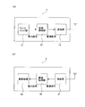
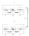
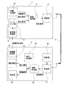
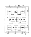
- FIG. 1A is a block configuration diagram of a power supply device
- FIG. 1B is a block configuration diagram of a power receiving device constituting the power supply system according to the disclosure of the present specification.
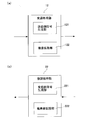
- 2A and 2B are diagrams for explaining a modulation processing unit and a demodulation processing unit of a power feeding device and a power receiving device by spectrum diffusion modulation processing
- FIG. 2A is a block configuration diagram of a modulation processing unit of the power feeding device
- FIG. It is a block block diagram of the modulation processing part of a power receiving device.
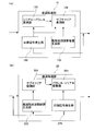
- FIG. 3 is a diagram illustrating a modulation processing unit of a power feeding device and a power receiving device in which the frequency arrangement of the multicarriers is asynchronous between the multicarriers and the frequency intervals are unequal and the frequency arrangement is approximately periodic.
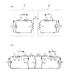
- FIG. 4 is a diagram illustrating a case where an approximate periodic frequency is transmitted as a resonance frequency of a magnetic field resonance method in a multicarrier of a power signal.
- FIG. 4A is a basic circuit configuration diagram
- FIG. 4B is the basic configuration. It is an equivalent circuit diagram of a circuit.
- FIG. 6 is a block configuration diagram of the power supply system according to the first embodiment.
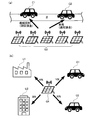
- 7A and 7B are views showing a specific embodiment of the first embodiment
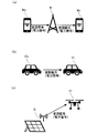
- FIG. 7A is a schematic diagram showing a state of electric power supply by a smartphone provided with a power supply device and a power receiving device
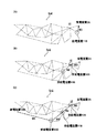
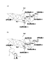
- (C) is a schematic diagram showing a state of power supply by an unmanned aerial vehicle (drone) equipped with a power supply device and a power receiving device. is there.
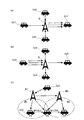
- FIG. 8 is a schematic view showing a power feeding mode in the case where the power feeding device and the power receiving device according to the first embodiment are automobiles, and FIG. 8A shows a plurality of moving bodies on the power feeding side and moving bodies on the power receiving side. Is singular, (B) is a case where the moving body on the power feeding side is singular and there are a plurality of moving bodies on the power receiving side, and (C) is a case where the moving body on the power receiving side continuously moves to an adjacent cell. It shows the power supply status of.
- FIG. 9 is a block configuration diagram of the power supply system according to the second embodiment.
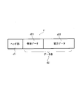
- FIG. 10 is. It is a schematic block diagram of the communication data transmitted to the power receiving device of 2nd Embodiment.
- FIG. 10 is a schematic block diagram of the communication data transmitted to the power receiving device of 2nd Embodiment.
- FIG. 11 is a block configuration diagram of the power supply system according to the third embodiment.
- FIG. 12 is a diagram showing a screen display example in the display unit of the power receiving device according to the third embodiment.
- FIG. 13 is a block configuration diagram of the power supply system according to the fourth embodiment.
- FIG. 14 is a block configuration diagram of the power supply system according to the fifth embodiment.
- FIG. 15 is a schematic view showing a state in which only the power supply device preset in the setting unit of the power receiving device according to the fourth embodiment receives power.
- FIG. 16 is a block configuration diagram of the power supply system according to the sixth embodiment.
- FIG. 17 is a diagram showing a specific embodiment when the power supply system according to the sixth embodiment is applied to a portable vital data measuring instrument.
- FIG. 18 is a block configuration diagram of the power supply system according to the seventh embodiment.
- FIG. 19 is a block configuration diagram of the power supply system according to the eighth embodiment.
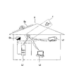
- FIG. 20 is a schematic view showing a state in which power is supplied to power receiving devices having different power supply conditions in the power supply condition processing unit of the power supply system according to the eighth embodiment, and
- FIG. 20A is a schematic diagram of an automobile passing through a predetermined place.
- FIG. 21 is a block configuration diagram of the power supply system according to the eighth embodiment.
- FIG. 21 is a block configuration diagram of the power supply system according to the eighth embodiment.
- FIG. 22 is a schematic view showing a state in which a power supply target is selected and power is supplied according to a status information signal from the power receiving device in the selection unit of the power supply device of the power supply system according to the eighth embodiment.
- FIG. 23 is a block configuration diagram of the power supply system according to the ninth embodiment.
- FIG. 24 is a block configuration diagram of the power supply system according to the tenth embodiment.
- FIG. 25 is a diagram showing processing of a power storage unit, a log information generation unit, and a calculation unit when power reception and power supply are performed in the power supply system according to the tenth embodiment.
- FIG. 26 is a block configuration diagram of a modified example of the power supply system according to the tenth embodiment.
- FIG. 27 is a schematic diagram showing a specific embodiment when the power supply system according to the tenth embodiment is applied to a smart home.
- FIG. 28 is a block configuration diagram of the power supply system according to the eleventh embodiment.
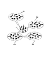
- FIG. 29 is a schematic diagram showing a specific embodiment when the power supply system according to the eleventh embodiment is applied to a smart city.
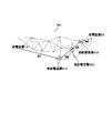
- FIG. 30 is a schematic diagram showing a supply system by selecting the shortest path of the power supply system.
- FIG. 31 is a schematic diagram showing a supply system by dynamic route selection of a power supply system, (A) is route selection at time t1, and (B) is route selection at time t2. (C) is a schematic diagram showing the route selection at the time t3.
- FIG. 31 is a schematic diagram showing a supply system by dynamic route selection of a power supply system, (A) is route selection at time t1, and (B) is route selection at time t2.
- (C) is a schematic diagram showing the route selection at the time t3.
- FIG. 32 is a schematic diagram showing a supply system by route selection according to the priority condition of the power supply system, (A) is route selection according to the priority condition on the power receiving device side, and (B) is a power supply device. It is a schematic diagram which showed the route selection according to the priority condition of the side.
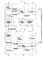
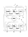
- FIG. 1 is a block configuration diagram showing an outline of a power supply device according to the disclosure of the present specification and a power receiving device constituting the power power supply system.
- the block configuration diagram of FIG. 1 is a schematic diagram composed of only necessary components for explaining the features of the disclosure of the present specification, and the general components required for power transmission / reception are simplified. ing.
- the power supply device and the power receiving device are each configured as a dedicated device, and as will be described later, they are mobile terminals having functions other than the power feeding and power receiving functions, and the power feeding device and the power receiving device are provided. Some have both functions of receiving power.
- FIG. 1A is a block configuration diagram of the power feeding device.
- the power feeding device 1 assigns a baseband signal before modulation, that is, a baseband unit 11 that generates a power signal, and a code that identifies a transmission source of the power signal generated by the baseband unit 11, the power signal. It is composed of a modulation processing unit 12 that modulates the above and generates a modulation signal that can be demolished by a power receiving device described later, and a transmission unit 13 that transmits the modulation signal generated by the modulation processing unit 12.
- FIG. 1B is a block configuration diagram of the power receiving device.
- the power receiving device 2 is obtained by the receiving unit 21 that receives the modulated signal generated by the power feeding device 1 via a predetermined transmission line, the demodulation processing unit 22 that demodulates the received modulated signal, and the demodulation processing. It is composed of a power receiving unit 23 that receives the power signal.
- the transmission line between the power supply device 1 and the power receiving device 2 is a power line by power line carrier communication (PLC: Power Line Communication) and high-speed power line carrier communication (BPL: Broadband over Power Lines), in addition to non-contact (wireless). It may be through. Further, also in the case of the wireless, the power transmission method is not particularly limited. That is, transmission via any of non-radiative magnetic field coupling type (electromagnetic induction type, magnetic field resonance type), electric field coupling type, evanescent wave type, radiative radio wave type (microwave, etc.), laser type, etc. It may be a road.
- non-radiative magnetic field coupling type electromagagnetic induction type, magnetic field resonance type
- electric field coupling type evanescent wave type
- radiative radio wave type microwave, etc.
- laser type etc. It may be a road.
- FIG. 2 is a diagram illustrating a modulation processing unit 12 and a demodulation processing unit 22 of a power feeding device and a power receiving device by spectral diffusion modulation processing. That is, the power signal is given a spread code by the spectral spread modulation process, and is multiplied by the power signal to generate a modulated signal.
- the modulation processing unit 12 uses a high-speed code sequence to generate a spreading code, a transmitting side code generating unit 121, and a complex spreading unit that executes complex number diffusion from the two code sequences. It has a portion 122.
- FIG. 2 is a diagram illustrating a modulation processing unit 12 and a demodulation processing unit 22 of a power feeding device and a power receiving device by spectral diffusion modulation processing. That is, the power signal is given a spread code by the spectral spread modulation process, and is multiplied by the power signal to generate a modulated signal.
- the modulation processing unit 12 uses a high-speed code sequence to generate a
- the demodulation processing unit 22 of the power receiving device includes the receiving side code generating unit 221 that generates the same diffusion code as the transmitting side code generating unit 121 and the receiving unit 22 shown in FIG. 1 (b).
- the unit 21 has a complex despreading unit 222 that is transmitted from the transmitting unit 13 of the feeding device 1 and despreads the modulated signal received by the receiving unit 21.
- the chaotic spreading code with a constant power has a high SN ratio of the received signal, and even among the spreading codes, the amount of information carried on the radio wave increases dramatically and the fading resistance is strong. Therefore, when transmitting the power signal, the power signal is transmitted. Is also suitable.
- the transmitting side code generation unit 121 first generates a diffusion code for any one of ⁇ (p-1) primitive roots q 1 , q 2 , ..., Q ⁇ (p-1) with respect to the prime number p.
- any of the integers 0, 1, 2, ..., P-1 is accepted as the number k for generating the diffusion code.
- the complex diffusion code b (q, k) of length p (exp (i ⁇ ), exp (2 ⁇ i ⁇ q 0 + k / p), exp (2 ⁇ i) ⁇ q 1 + k / p), exp (2 ⁇ i ⁇ q 2 + k / p), ..., exp (2 ⁇ i ⁇ q (p-2) + k / p)) is generated.
- the complex diffusion code b (q, k) (exp (i ⁇ ), 1,1, ..., 1) having a length p is generated.
- the primitive root q is given as a primitive root for generating a chaos diffusion code
- the integer k is given as an identification number for generating a chaos diffusion code
- one complex diffusion code b (q, k) is generated.
- the complex diffusion unit 122 diffuses one power signal to be transmitted by the complex diffusion code b (q, k) generated for the integer k.
- the receiving side code generation unit 221 of the demodulation processing unit 22 also gives the primitive root q as the primitive root for generating the diffusion code, and gives the integer k as the identification number for generating the diffusion code, and is complex. Generate a diffusion code. That is, since the power feeding device 1 and the power receiving device 2 share the primitive root q and the identification number k, they share the complex diffusion code b (q, k) of length p.
- the complex despreading unit 222 of the demodulation processing unit 22 receives the received power signal.
- the power signal is obtained by despreading by the spreading code b (q, k) generated for the integer k.
- the complex diffusion code b (q, k) has perfect orthogonality and has good autocorrelation characteristics.
- the parameters for determining each of the K almost periodic function codes are It is represented by ⁇ + (k-1) / K.
- the number of codes corresponding to the number of users or the number of channels is used for modulation.
- K is preferably N or 2N (N is the code length of the almost periodic function code), and ⁇ is preferably a real number larger than 0 and less than 1 / N.
- the power feeding device 1 using the almost periodic function code includes a modulation processing unit 12 that modulates the power signal, as shown in FIG. 1A.
- the modulation processing unit 12 outputs a modulation signal by applying an almost periodic function code to the power signal.
- the modulation signal (transmission data) transmitted by the transmission unit 13 may be one to which primary modulation such as BPSK, QPSK, 16QAM is applied.
- the modulation signal output from the modulation processing unit 12 is received by the power receiving device 2 through the transmission line, demodulated by the demodulation processing unit 22, and supplied with power by the power receiving unit 23.
- the frequency arrangement of the multicarriers is asynchronous between the multicarriers, and the frequency intervals are non-equal intervals will be described.
- the almost periodic frequency arrangement is a frequency arrangement that is asynchronous between any subcarriers with respect to the frame time length that divides the signal string, includes non-equidistant intervals, and is an almost periodic frequency (Almost).
- Period Frequency refers to the frequency of each subcarrier on the almost periodic frequency arrangement.
- each subcarrier has an almost periodic frequency arrangement that is asynchronous with respect to the frame time length, it is possible to suppress an increase in PAPR even if the number of carriers is increased.
- FIG. 3 is a diagram illustrating a modulation processing unit 12 and a demodulation processing unit 22 of a power feeding device and a power receiving device in which the frequency arrangement of the multicarriers is an almost periodic frequency arrangement.
- the serial / parallel conversion unit 124 converts the power signal (serial code) into a parallel number corresponding to the multiplex code length N. Convert to the parallel code you have.
- a parallel code having a code length N is a transmission code.
- the subcarrier modulation unit 125 performs almost periodic frequency multiplex modulation according to Equation 1.
- the subcarrier modulation unit 125 performs subcarrier modulation of the transmission code (d 1 d 2 d 3 ... d N-1 d N ) having a code length N, and performs a code sequence (y 1 y 2 y 3 .... y N-1 Outputs the approximate periodic frequency arrangement multicarrier signal indicated by y N ).
- the subcarrier modulation unit 125 performs multicarrier modulation based on the multicarriers given by the almost periodic frequency arrangement generation unit 123.
- the approximate periodic frequency arrangement generation unit 123 includes, for example, a prime number group storage unit (not shown), an approximate periodic frequency group calculation / storage unit, a reference frequency arrangement calculation / storage unit, and an approximate periodic frequency arrangement search / storage unit. Anything that has The prime number group storage unit stores a large number (for example, 10 million) of prime numbers used for calculating the almost periodic frequency.
- the approximate periodic frequency group calculation / storage unit calculates and stores the approximate periodic frequency using the prime numbers stored in the prime number group storage unit.
- the calculation / storage unit of the reference frequency arrangement calculates and stores the reference frequency arrangement used for determining the almost periodic frequency arrangement.
- the search / storage unit of the general periodic frequency arrangement searches for and selects an approximate periodic frequency close to the reference carrier frequency in the reference frequency arrangement from the general periodic frequency group, determines the general periodic frequency arrangement, and determines the said. Memorize the almost periodic frequency arrangement.
- Equation 1 the matrix having the elements ak bk to pk (1 ⁇ k ⁇ N) is an N ⁇ N matrix.
- ⁇ dk is a prime number used to generate the kth frequency in an almost periodic frequency arrangement having N carriers.
- ⁇ k is an arbitrary real number and may be 0.
- Equation 1 although not explicitly defined elements a k b k other elements c k ⁇ p k, A k included in the definition of the elements a k b k, the B k , C k to P k .
- C k ⁇ P k are A k, the amplitude value of the k-th carrier in the same manner as B k.
- the subcarrier signal output from the subcarrier modulation unit 125 is given to the transmission unit 13 in FIG. 1A and transmitted to the power receiving device 2 as an almost periodic subcarrier output signal (almost periodic frequency subcarrier synthesis signal). ..
- the serial / parallel conversion unit 124, the subcarrier modulation unit 125, and the transmission unit 13 operate based on the synchronization signal given from the synchronization signal generation unit 126.
- the demodulation processing unit 22 includes a subcarrier demodulation unit 224, an almost periodic frequency arrangement generation unit 223, a parallel / serial conversion unit 225, and a synchronization signal generation unit 226.
- the receiving unit 21 of FIG. 1B receives the input of the received modulation signal (almost periodic frequency subcarrier synthesis signal) and gives the received modulation signal to the subcarrier demodulation unit 224.
- the subcarrier demodulation unit 224 has a mutual correlation value (complex correlation) between the approximate periodic frequency used on the transmitting side of the received modulated signal (approximately periodic frequency arrangement for demodulation; approximate periodic complex carrier wave) and the received modulated signal. Demodulation is performed by obtaining the value).
- the frequency of the almost periodic frequency arrangement for demodulation is given by the almost periodic frequency arrangement generation unit 223.
- the cross-correlation value of the signal for example, the “method of obtaining on the time axis” of the formula 2 or the “method of obtaining from the cross spectrum” of the formula 3 can be adopted.
- the signal output from the subcarrier demodulation unit 224 is converted into serial data by the parallel / serial conversion unit 225.
- This serial data is output as a demodulated power signal to the power supply unit 23 shown in FIG. 1 (b), and power is supplied.
- the receiving unit 21, the subcarrier demodulation unit 224, the almost periodic frequency arrangement generation unit 223, and the parallel serial conversion unit 225 in FIG. 1B operate based on the synchronization signal given from the synchronization signal generation unit 226.
- FIG. 4A is a basic circuit configuration diagram for transmitting an approximate periodic frequency as a resonance frequency of a magnetic field resonance coupling method (magnetic field resonance method) in the multicarrier of the power signal described with reference to FIG. That is, it is a circuit diagram of a series secondary series capacitor system (SS system) in which the modulation processing unit 12 of the power feeding device 1 has a primary side circuit and the demodulation processing unit 22 of the power receiving device 2 has a secondary side circuit. Since modulation by the approximate periodic frequency arrangement (signals of different frequencies corresponding to the sources) can be realized by matching the frequency with the resonance frequency of the magnetic field resonance method, the power signal is transmitted by a known basic circuit. To do. As shown in FIG.
- SS system series secondary series capacitor system
- both the primary side circuit and the secondary side circuit have an RLC series circuit configuration
- C 1 is the resonance capacitance of the primary side circuit
- r 1 is the primary side.
- the line resistance of the circuit L 1 is the reactance of the coil of the primary side circuit
- C 2 is the resonance capacitance of the secondary side circuit
- r 2 is the line resistance of the secondary side circuit
- L 2 is the secondary side circuit.
- It is the reactance of the coil of the side circuit
- RL is the load of the secondary side circuit
- L m is the mutual inductance between L 1 and L 2 .
- FIG. 4B is an equivalent circuit diagram of the basic circuit configuration diagram.
- ⁇ L m of leakage inductance is integrated with L m and described, but it is explicitly shown in FIG. 4 (b).
- the primary circuit side V 1 the voltage (power supply side), the secondary circuit side (load R L side) of the V 2 voltage
- the primary circuit V C1 the voltage across the resonant capacitor C 1 of the primary the voltage applied to the reactance L 1 of the coil side circuit V L1
- the voltage across the resonant capacitor C 2 of the secondary side circuit V C2 the secondary circuit reactance L 2 voltage V L2 according to the coil, the secondary line resistance r 2 in accordance with the voltage V r2 of the circuit
- the primary circuit of the output voltage V Lm1 input of the secondary circuit
- the voltage of the primary side circuit and the voltage of the secondary side circuit are given in Equations 4 and 5
- the resonance condition of the secondary circuit is mathematical formula 8
- the resonance frequency of the primary circuit is mathematical formula 9.
- the resonance frequency will be as shown in Equation 10.
- the power signal of the approximate periodic frequency transmitted from the power supply device 1 having the primary side circuit resonates with the power signal of the approximate periodic frequency of the power receiving device 2 having the secondary side circuit. It is possible to receive power only at.
- only the desired power signal can be identified on the power receiving device 2 side, and power can be selectively received.
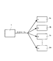
- FIG. 6 shows the basic configuration of the power supply system.
- a transmission line 3 is interposed for transmitting a power signal from the power supply device 1 described in FIG. 1 (a) to the power receiving device 2 described in FIG. 1 (b).
- the transmission line 3 indicates a frequency band.
- FIG. 7A is an example in the case where the mobile body is a smartphone, in which a modulation signal, that is, a power signal is transmitted from the power supply side smartphone Ms to the power reception side smartphone Mr via the power supply base station B. Is shown.
- a smartphone Ms connected to an information communication base station on an information communication network transmits power supply instruction data to a remote smartphone Mr. via the information communication base station. And based on this power supply instruction data, power may be supplied from the power supply base station B within the range in which the smartphone Mr can receive power (not shown).
- the power supply base station B itself is also connected on the information communication network so that the power supply instruction data can be received. Further, a plurality of power supply base stations B are connected to the information communication network, and any of the power supply base stations B can receive the power supply instruction data, and the power supply base station B most suitable for the smartphone Mr. (Usually, the power supply base station B that exists at the shortest distance from the smartphone Mr.) may be used for power supply.
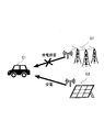
- FIG. 7B is an example in the case where the moving body is an automobile, and shows a case where a power signal is transmitted from the moving power supply side automobile Cs to the power receiving side automobile Cr moving in the same direction. Is. FIG.
- FIG. 7C is an example in the case where the moving body is an unmanned aerial vehicle (drone), and shows a case where a power signal is transmitted from the power generation device G to the drone Fr.
- the moving body is an unmanned aerial vehicle (drone)
- FIG. 8A power is supplied from the power feeding side vehicles Cs1, Cs2 and Cs3 (three units) to the power receiving side vehicle Cr1 via the power supply base station B. That is, it is possible to supply power from a plurality of power supply side vehicles to a single power receiving side vehicle, and in this case, there is a “many-to-one” power supply relationship.
- power is supplied from the power feeding side vehicle Cs4 (1 unit) to the power receiving side vehicles Cr2, Cr3 and Cr4 (3 units) via the power supply base station B. That is, it is possible to supply power from a single power supply side vehicle to a plurality of power receiving side vehicles, and in this case, there is a “one-to-many” power supply relationship.
- a "many-to-many" power supply relationship including both the “many-to-one” and “one-to-many” relationships is also established.
- the disclosure of the present specification is that since the electric power to be supplied can be signalized and transmitted together with the information signal, it is possible to supply power from a plurality of moving vehicles (moving bodies) to a plurality of moving vehicles (moving bodies) at the same time. It has a remarkable effect that is not found in.
- FIG. 8C is a schematic diagram in the case where the power feeding side vehicle Cs5 supplies power to the power receiving side vehicle Cr5 in motion via the power supply base station B1.
- the vehicle At the start of power supply from the power supply side vehicle Cs5 to the power supply side vehicle Cr5, the vehicle is traveling in the cell R1 of the power supply base station B1, but when it moves into the cell R2 of the power supply base station B2 during the power supply, it is so-called.
- the modulation signal is inherited from the power feeding base station B1 to the power feeding base station B2 by the soft handover, and power is continuously supplied to the power receiving side automobile Cr5.
- the power is continuously supplied by the soft handover.
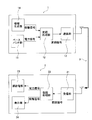
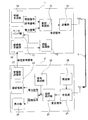
- FIG. 9 is a block configuration diagram of a second embodiment of the power supply system.
- the power feeding device 1 includes an information generation unit 14 that generates an information signal related to the power signal.
- the information signal generated by the information generation unit 14 is multiplexed together with the power signal generated by the baseband unit 11 and generated as a modulation signal by the modulation processing unit 12.
- the communication data d of the power signal and the modulation signal generated from the information signal has the structure shown in FIG. That is, the communication data d is composed of a fixed-length header unit d1 such as source information, destination information, and length information, and a variable-length data unit d2, and the data unit d2 includes information data d21 and power data d22. Consists of.
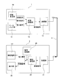
- FIG. 11 is a block configuration diagram of a third embodiment of the power supply system.
- the power receiving device 2 that has received the modulated signal has a display unit 24 that displays the information signal obtained together with the power signal after demodulation processing by the demodulation processing unit 22 with at least either visible information or audible information.
- the display unit 24 may be, for example, a display, a speaker, or the like.
- the display unit 24 displays predetermined information related to the power signal based on the information signal.
- receiver information 24a, source information 24b, environmental value information 24c, electric energy information 24d, and billing information 24e are displayed as an example.
- environmental value information means, for example, that the company issuing the certificate obtains the environmental value added value of electricity generated by natural energy and obtains the securitized environmental value certificate from a third-party certification body. Information that indicates that you are doing something.
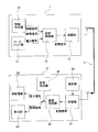
- FIG. 13 is a block configuration diagram of a fourth embodiment of the power supply system.
- the information generation unit 14 of the power feeding device 1 generates an encrypted signal
- the modulation processing unit 12 generates an encrypted modulation signal.
- the power receiving device 2 demodulates the encrypted modulated signal in the demodulation processing unit, decodes it in the decoding processing unit 25, and returns it to plain text. By interposing such processing, it is possible to prevent so-called power hacking.
- FIG. 14 is a block configuration diagram of a fifth embodiment of the power supply system.
- FIG. 14 has a setting unit 26 that receives only a power signal based on predetermined power supply condition information in advance in the power receiving device 2.
- the power supply condition information signal is included as the information signal generated by the information generation unit 14 of the power supply device 1, and when the power supply condition information signal is received by the reception unit 21 of the power reception device 2, the power supply condition information signal becomes. It is determined whether or not the power signal is based on the power supply condition set by the setting unit 26, and the received modulation signal is demodulated by the demodulation processing unit 22 only when the power signal is based on the power supply condition set. ..
- the power supply condition information is, for example, power generation-derived proof information (power generated from a predetermined power generation) that certifies whether the power to be supplied is generated by renewable energy or fossil energy.
- Power supply condition information for receiving only power power generation-derived proof information (power generated from a predetermined power generation) that certifies whether the power to be supplied is generated by renewable energy or fossil energy.
- Power supply condition information for receiving only power power charge information (power supply condition information for receiving only power of a predetermined power charge), etc., but are not limited thereto. That is, the conditions may be such that the consumer side contributes to the determination of whether or not to accept the power received from the power supply device 1.
- the power generation origin certification information of the power plant G1 is fossil energy. If the power generation origin certification information of the power plant G2 is based on renewable energy (for example, solar energy), the automobile C has only the power signal derived from renewable energy in the setting unit 26. When it is set to accept, the reception of the power signal from the power plant G1 is rejected, and only the power signal from the power plant G2 is received.
- renewable energy for example, solar energy
- FIG. 16 is a block configuration diagram of a sixth embodiment of the power supply system.
- the power receiving device 2 has a power receiving side transmitting unit 27 that transmits a power feeding request signal to a predetermined power feeding device 1, and the power receiving device 1 has a power feeding side receiving unit 15 that receives the power feeding request signal.
- an oscillation circuit (not shown) is activated by the reception of the power supply request signal as a trigger. Then, a power signal is generated in the baseband unit 11.
- the power supply request signal may be transmitted from the power receiving side transmitting unit 27 when the power receiving device 2 reaches a predetermined threshold value.
- the predetermined threshold value may be at least the remaining amount of electricity stored in the power receiving device 2, the usage time of the power receiving device 2, and the like. For example, when the load connected on the power receiving device 2 side is a device that is required to be constantly operated, the remaining stored amount, the usable time with respect to the charged amount, and the like are measured, and the predetermined remaining amount of electricity and the predetermined cumulative usage time are measured. Is set in advance as a threshold value, and when it is detected that the threshold value has been reached, the power supply request signal may be transmitted.
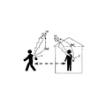
- FIG. 17 is a portable vital data measuring instrument V, which is worn on the arm of the person to be measured, for example.
- the charging unit of the portable vital data measuring instrument V is connected to the power receiving device (not shown), detects the remaining charge amount and the cumulative usage time of the charging unit, and determines a predetermined threshold value. When it reaches, the power supply request signal Ds1 is transmitted to the indoor power supply device 1A. Similarly, when the person to be measured is outdoors, when a predetermined threshold value is reached, the power supply request signal Ds2 is transmitted to the outdoor power supply device 1B.
- Vital data for example, blood glucose level, blood pressure level, etc.
- Vital data can be accurately medically judged by continuously measuring how it changes with changes in the environment.
- the power supply request signal is associated with the ID signal of each person to be measured, and each subject is linked.
- the measurer may be distinguished and power may be supplied from one power supply device according to each person to be measured.
- the device since power can be supplied to various devices frequently, it is possible to reduce the size (lightening) of the charging equipment held by the various devices. For example, if the device is a smartphone, it may be smaller.
- the usage time can be extended, and the cruising range can be extended for moving objects such as automobiles and unmanned aerial vehicles.
- FIG. 18 is a block configuration diagram of a seventh embodiment of the power supply system.
- the power supply side receiving unit 15 of the power feeding device 1 receives the power supply request signal from the power receiving device 2, it authenticates in order to determine whether or not to feed the power receiving device 2 that has transmitted the power supply request signal. Authentication processing is performed by the processing unit 16. Therefore, the power receiving device 2 transmits the authentication information (for example, ID, password) required for the authentication process together with the power supply request signal (not shown).
- the authentication information for example, ID, password
- the power receiving device 2 that has received the modulation signal from the transmission unit 13 of the power supply device 1 by the reception unit 21 is described.
- the authentication process may be performed after the power supply side receiving unit 15 receives the transmission of the authentication information by requesting the transmission of the authentication information (not shown).
- FIG. 19 is a block configuration diagram of an eighth embodiment of the power supply system.
- the power supply device 1 has a power supply condition processing unit 17 that changes the power supply condition depending on whether the power receiving device 2 is authenticated or not in the authentication processing unit 16 described with reference to FIG.
- the power supply condition processing unit 17 generates each power signal from the baseband unit 11 based on different power supply conditions depending on whether or not the authentication is permitted or not. For example, when a power signal is transmitted to all automobiles passing through a predetermined place such as a so-called drive-through, the authentication processing unit 16 identifies a member and a non-member of a store that provides the drive-through, and performs power supply condition processing. In part 17, processing such as changing the amount of electric power supplied to each automobile becomes possible.
- FIG. 20 shows a processing example in the power supply condition processing unit 17.
- FIG. 20A shows an automobile C1 as a power receiving device that constantly uses the road R and an automobile that accidentally uses the photovoltaic power generation device group G3 as a power supply device installed in a predetermined passing area (road R). It is a figure which showed the state which performs the process of changing the power supply condition so as to change the charge of the power which is supplied from the photovoltaic power generation apparatus group G3 with C2. That is, since the automobile C1 concludes a continuation contract and has an ID as a contractor, it is authenticated by the authentication processing unit 16 and charged by the power supply condition processing unit 17 at a bargain rate under the continuation contract. Will be processed. On the other hand, since the automobile C2 does not have the ID as the contractor, it is not authenticated by the authentication processing unit 16 and is processed so as to be charged by the power supply condition processing unit 17 at a normal charge.
- FIG. 20B shows authentication when power is supplied from the photovoltaic power generation device G4 as the power supply device to each power receiving device (vehicle C1, vehicle C2, fixed equipment U1, fixed equipment U2) of the power supply destination.
- the processing unit 16 individually identifies each of the power receiving devices by performing authentication processing, and the power supply condition processing unit 17 prioritizes the power supply so that the power supply amount of each power receiving device can be changed. Is. That is, the total amount of power supplied by the photovoltaic power generation device G4 at a certain point in time is not evenly divided among the four power receiving devices to which the power is supplied, but different amounts of power can be supplied according to the priority. In the present embodiment, it is shown that 10% of the total palaceable amount of the photovoltaic power generation device G4 is transmitted to the automobile C1, 20% to the automobile C2, 40% to the fixed equipment U1, and 30% to the fixed equipment U2. There is.
- FIG. 21 is a block configuration diagram of a ninth embodiment of the power supply system.
- the power feeding device 1 receives the power receiving side status information from the power receiving side transmitting unit 27 of the power receiving device 2, it collates with the power feeding side status information of the power feeding device 1 and collates with the power receiving side status information, and has a predetermined relationship with the power receiving side status information.
- It has a selection unit 18 that selects the power receiving device 2 that has transmitted the status information as the power supply destination.
- the status information includes, for example, the position of the moving body (distance between the power feeding device 1 and the power receiving device 2), the time (for example, the sunshine time when the power feeding means is a person who uses renewable energy), and so on.
- the predetermined relationship means a relationship in which power can be efficiently supplied, for example, when the power feeding device 1 and the power receiving device are moving bodies, or when the moving directions are the same or similar.
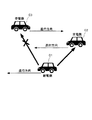
- FIG. 22 is a diagram showing the movement direction of the moving body as an example of the predetermined relationship in the status information. That is, when the power feeding side vehicle C1 is traveling in a predetermined direction, the power receiving side vehicle C2 and the power feeding side vehicle C1 moving in the same traveling direction as the power feeding side vehicle C1 travel in the opposite directions. It shows a state in which the power receiving side automobile C3 is present.
- the selection unit 18 of the power feeding side vehicle C1 receives the power receiving side status information indicating that the vehicle is traveling in the same direction from the power receiving side vehicle C2, and is traveling in the opposite direction from the power receiving side vehicle C3. Receives power receiving side status information indicating.
- the selection unit 18 collates its own power supply side status information with the two power receiving side status information, and determines that the selection unit 18 has a predetermined relationship that the power receiving side status information of the power receiving side vehicle C2 is traveling in the same direction. Then, the power receiving side vehicle C2 is selected as the power supply destination. On the other hand, the power receiving side vehicle C3 that has transmitted the power receiving side status information indicating that the vehicle is traveling in the opposite direction is not selected as the power supply destination from the viewpoint of efficiency when comparing the relationship with the power receiving side vehicle C2.
- the power supply side vehicle C1 refuses the power supply.
- FIG. 23 is a block configuration diagram showing a power receiving / receiving device 4 constituting the tenth embodiment of the power feeding system.
- the power receiving and feeding device 4 can receive power from the power feeding device 1 and also supply power to the power receiving device 2. It mainly functions as a relay device (node) in the power supply network described later.
- the configuration of the power receiving device 4 has the same configuration as that of the power receiving device 1 and the power receiving device 2.
- the power receiving unit 41 of the power receiving / feeding device 4 has a receiving unit 413, a demodulation processing unit 412, and a power receiving unit 411, and the power feeding unit 42 has a baseband unit 421, a modulation processing unit 422, and a transmitting unit 423 (
- the same embodiment of the 1st embodiment is illustrated in this embodiment, it may be the same as the configuration of the 2nd embodiment to the 9th embodiment).
- the power receiving / receiving device 4 may include a power storage unit 43 that stores a part or all of the received electricity.
- the power storage unit 43 can store the electric power received by the power receiving / power receiving device 4 in the power storage unit 43, and supply power to the other power receiving device 2 and the power receiving / power receiving device 4 at an arbitrary timing.
- FIG. 24 is a first modification of the power receiving / receiving device 4 according to the tenth embodiment.
- a log information generation unit that generates information on the power receiving source and the amount of power received, information on the power supply destination, and the power supply amount at predetermined time intervals, and a calculation unit that calculates the difference between the power reception amount and the power supply amount.
- the generation unit 44 generates log information regarding power reception and power supply
- the calculation unit 45 calculates the difference between the power reception amount and the power supply amount.
- FIG. 26 is a second modification of the power receiving / receiving device 4.
- the power receiving / receiving device 4 has a control unit 46 that distributes the received power to a plurality of load facilities supplied from the power receiving / power receiving device 4 as needed. Further, the control unit 46 distributes electric power that complements the electric power that is distributed from the existing power distribution equipment other than the power receiving / receiving device 4 to the plurality of load equipment.
- FIG. 27 is a diagram showing a specific embodiment of the second modification.
- the power receiving / receiving device 4 is installed in the so-called smart home H.
- the control unit 46 of the power receiving / receiving device 4 supplies electric power to the load facilities L1 to L3 used in the smart home (in this modified example, L1 is a refrigerator, L2 is a television set, and L3 air conditioner). .. Further, the control unit 46 distributes power from the existing distribution equipment (solar panel Sp, existing distribution equipment supplied from the distribution line of the electric power company via the distribution board Db) to the load equipment L1 to L3. Distributes power that complements power.
- the existing distribution equipment solar panel Sp, existing distribution equipment supplied from the distribution line of the electric power company via the distribution board Db
- control unit 46 may monitor the excess of the amperage capacity in the existing power contract, and if there is a possibility of exceeding the ampere capacity, switch only the predetermined load equipment to receive the power supply from the power receiving / receiving device 4. Further, the control unit 46 may monitor the power consumption of the entire smart home H and control the standby power of various load facilities. Further, the control unit 46 may monitor the power consumption of the entire smart home H and operate the power supply unit 42 in order to sell the surplus power. In this case, the log information generation unit 44 and the calculation unit 45 can also know the information of the power sale destination.
- the power receiving / feeding device 4 may be in a form in which the power receiving unit 31 and the power feeding unit 42 are integrated, or in a form in which the power receiving unit 41 and the power feeding unit 42 are connected separately.
- FIG. 28 is a block configuration diagram of the eleventh embodiment of the power supply system.
- a plurality of power feeding devices 1, a power receiving device 2, and a power receiving and power receiving device 4 in a predetermined area are formed as a cluster CL1, and a collecting unit 61 and another cluster CL2 for collecting power for feeding the cluster CL1.
- It has a collection / delivery server 6 including a distribution control unit 62 that supplies power collected for power supply to the cluster CL3.
- each power feeding device 1, power receiving device 2, and power receiving device 4 includes a meteorological observation detection unit 5, and detects various meteorological data at each location.
- the meteorological data is, for example, temperature data, humidity data, atmospheric pressure data, wind direction data, sunshine time data, and crustal movement data, but is not limited thereto.
- the meteorological observation detection unit 5 is fed by the power feeding device 1 or the power receiving / receiving device 4 so as to always operate.
- the collection / delivery server 6 predicts the excess / deficiency data of the power of another cluster unit based on the storage unit 63 that stores the weather data detected by each weather observation detection unit 5 and the accumulated weather data.
- It has a power demand forecasting unit 64.
- the electric power demand forecasting unit 64 may, for example, predict the electric power demand for each cluster by using the past data of the correlation between the change of the meteorological data and the electric power consumption.
- the distribution control unit 62 calculates excess / deficiency data based on the power demand predicted by the power demand forecasting unit 64, and supplies power to the cluster predicted to be short of power.
- the collection unit 61, the distribution control unit 62, the storage unit 63, and the power demand forecast unit 64 have been described as elements constituting the collection / delivery server 6, but each of them is connected by another device. It may be a thing. Further, in the present embodiment, the example of detecting the meteorological observation data by the meteorological observation detection unit 5 has been described, but the configuration is not limited to the meteorological observation data, but the satellite data and other data contributing to the power demand forecast are detected (data). It may be a detection unit).
- FIG. 29 is a specific example in which the power supply system described in FIG. 28 is formed in a smart city.
- Clusters CL1 to CL4 are formed, and the power feeding device 1, the power receiving device 2, and the power receiving device 4 constituting each cluster are mobile bodies that temporarily exist in the cluster, such as an automobile, in addition to the smart home described with reference to FIG. It may be.
- a smart city is formed as in the present embodiment, it is possible to provide effective and timely support for power supply when another area (cluster) is damaged in units of areas (clusters).
- the clusters CL1 to CL3 are supporting the power supply to the cluster CL4. Note that, unlike the cluster CL3, the power may be directly supplied to the cluster CL4 without going through the collection / delivery server 6.
- the collection / delivery server 6 is installed in an area that does not belong to any cluster, but it may be installed in any cluster. In any case, power may be supplied to various devices (particularly mobile bodies) around the place where the collection / delivery server 6 is installed.
- the data obtained from the portable vital data measuring instrument V as described in FIG. 17 can be aggregated in cluster units, and by acquiring and aggregating the vital data of residents by region, it is related to health. It will be possible to identify regional characteristics and can be expected to contribute to medical measures.
- the (12th Embodiment) 30 to 32 are schematic views of a power supply network for explaining the twelfth embodiment of the power supply system.
- the power supply system according to the present embodiment has a calculation unit that calculates a route in order to form a power supply network that supplies power from the power supply device to the power reception device via a plurality of power reception devices (nodes).
- the arithmetic unit may be calculated by P2P communication in addition to the server dedicated to the arithmetic unit (hereinafter, the arithmetic unit is not shown in the present embodiment).
- FIG. 30 is a schematic diagram showing the supply system Sn1 by selecting the shortest path of the power supply system.
- the calculation unit calculates the shortest distance route.
- a known algorithm for example, Dijkstra's algorithm
- the shortest distance may change dynamically due to the installation of a new node, etc., but basically the power supply route can be determined before power supply, so it can be fixedly set in advance.
- the shortest distance feeding network Sn1 is formed by the paths W1, W2, W3 and W3 between the power receiving device 1A, the power receiving device 41A, the power receiving device 42A, and the power receiving device 2A via the power receiving device 43A.
- the power receiving and receiving devices 41A to 43A can receive the transaction fee associated with the power feeding (the same applies to the respective modes of FIGS. 31 and 32 below).
- the long-distance feeding path can be configured in short-distance units, so that the feeding efficiency is improved.
- FIG. 31 shows a form in which the route of the power supply network Sn2 changes dynamically.
- the calculation unit selects the path W1 from the power supply device 11B as the optimum path at time t1 as the power supply path to the power receiving device 2A (FIG. 31 (A)), but receives and supplies power as the optimum path at time t2.
- the paths W2 and W3 via the device 41B and the power receiving / power receiving device 42B are selected (FIG. 31 (B)), and the power feeding device 12B, the power receiving / power receiving device 43B, the power receiving / receiving device 41B, and the power receiving / receiving power are supplied as the optimum paths at the time t3.
- the paths W4, W5, W2, and W3 via the device 42B are selected (FIG. 31 (C)).
- the calculation unit measures the power consumption of the plurality of routes of the power supply network Sn2 and dynamically changes the route based on the power supply reserve capacity data, so that the route is changed as time elapses from t1 to t3.
- the route changes dynamically.
- at least the power receiving / receiving device located in the middle of the path is provided with a power storage unit because it is in a standby state as a node.
- the power supply efficiency is improved when many-to-many power supply is performed.
- FIG. 32 is a schematic diagram showing a supply network by route selection according to the priority conditions of the power supply system.
- the power supply network Sn3 of FIG. 32 (A) is a schematic diagram showing route selection according to the priority condition on the power receiving device 2A side.
- the calculation unit selects the route according to the priority condition (described in FIGS. 14 and 15). This configuration is applied to the route selection of the entire power supply network).
- the calculation unit when the power receiving device 2A sets a predetermined priority condition, the calculation unit performs the paths Wp1, Wp2, Wp3 via the power feeding device 1C, the power receiving / power receiving device 41C, the power receiving / power receiving device 42C, and the power receiving / power receiving device 44C. , Wp4, Wp5 are selected.
- the power supply network Sn4 in FIG. 32 (B) is a schematic diagram showing route selection according to the priority conditions on the power supply device 1D side.
- the power supply device 1D is connected to the weather forecast server 7 via the Internet I and receives information (signal) about the disaster forecast in the area where the power receiving device 2A exists from the server 7, such reception is used as a trigger for calculation.
- the unit starts and calculates the optimum route from the power feeding device 1D to the power receiving device 2A.
- the calculation unit when the power supply device 1D sets a predetermined priority condition, the calculation unit performs the paths Wp6, Wp7, Wp8 via the power supply device 1D, the power supply / reception device 41D, the power supply / reception device 42D, and the power supply / reception device 44D. , Wp9, Wp10 are selected.
- the activation of the arithmetic unit is triggered by the reception of a signal from the server 7, but the arithmetic unit may be activated and the priority condition may be set without depending on an external signal.
- the power receiving / receiving device 44D may be, for example, one installed in a medical facility, one installed in a disaster countermeasures headquarters, one installed in a public evacuation center, or the like.
- the power supply device and the power supply system according to the disclosure of the present specification transmit the power signal after encoding the power signal in advance, they are highly robust and can supply power with a good SN ratio. Further, since a plurality of power signals can be transmitted without interfering with the coding, fading resistance is high, and radiative wireless power transmission between a plurality of moving bodies (many-to-one, one-to-many, many-to-many). It is suitable for.
- Power supply device Power receiving device 11
- Baseband unit Modulation processing unit 13
- Transmitter Information generator 15
- Power supply side receiver 21
- Receiver 22 Demodulation processing unit 23
- Power receiving unit 24
- Decoding processing unit 26
- Setting unit 27 Power receiving side transmitter
Landscapes
- Engineering & Computer Science (AREA)
- Computer Networks & Wireless Communication (AREA)
- Power Engineering (AREA)
- Signal Processing (AREA)
- Charge And Discharge Circuits For Batteries Or The Like (AREA)
- Battery Electrode And Active Subsutance (AREA)
- Near-Field Transmission Systems (AREA)
Abstract
Description
両方に共振周波数を一致させたコイル(L)とコンデ ンサ(C)で構成されるLC共振器を用いることで共鳴状態を作り出す方式では、大エアギャップ時に高効率かつ大電力が実現できることが知られている(例えば、非特許文献3参照。)
受電装置に給電するための電力信号を生成するベースバンド部と、
前記ベースバンド部で生成された前記電力信号の送電元を特定する符号を付与するために前記電力信号を変調し、前記受電装置で復調可能な変調信号を生成する変調処理部と、
前記変調処理部によって生成された変調信号を伝送する送信部と、
を有することを最も主要な特徴とする。
(第1実施形態)
図2は、スペクトル拡散変調処理による給電装置および受電装置の変調処理部12および復調処理部22を説明する図である。すなわち、電力信号が、スペクトル拡散変調処理によって、拡散符号が付与され、電力信号に乗積して変調信号を生成する。図2(a)で示す通り、変調処理部12は、高速符号系列を用いて、拡散符号を生成する送信側符号生成部121と、これを2つの符号系列から複素数の拡散を実行する複素拡散部122を有する。一方、図2(b)で示す通り、受電装置の復調処理部22は、送信側符号生成部121同様の拡散符号を生成する受信側符号生成部221と、図1(b)で示した受信部21で給電装置1の送信部13から送信され、受信部21で受信した変調信号を逆拡散する複素逆拡散部222とを有する。
k=0,1,2,…,p-2である場合、長さpの複素拡散符号 b(q,k)=(exp(iθ),exp(2πi×q0+k/p),exp(2πi×q1+k/p),exp(2πi×q2+k/p),…,exp(2πi×q(p-2)+k/p))を生成する。一方、k=p-1である場合、長さpの複素拡散符号 b(q,k)=(exp(iθ),1,1,…,1)を生成する。
第2実施形態では、前記拡散符号として、概周期関数符号を利用した形態を説明する。
第3実施形態では、マルチキャリアで伝送する場合であって、マルチキャリアの周波数配置が、マルチキャリア間で非同期であり、周波数間隔が非等間隔である概周期周波数配置とする形態を説明する。ここで、概周期周波数配置とは、信号列の区切りとするフレーム時間長に対して何れのサブキャリア間においても非同期である周波数配置であり、非等間隔な配置を含み、概周期周波数(Almost Periodic Frequnecy)とは、概周期周波数配置上の各々のサブキャリアの周波数をいう。



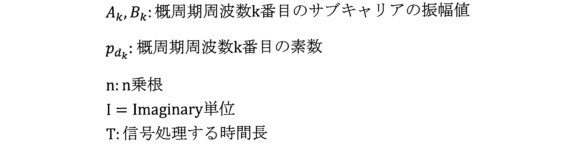


図4(a)は、図3で説明した電力信号のマルチキャリアにおいて、概周期周波数を磁界共振結合方式(磁界共鳴方式)の共振周波数として送電するための基本回路構成図である。すなわち、給電装置1の変調処理部12に一次側回路を有し、受電装置2の復調処理部22に二次側回路を有する直列二次直列コンデンサ方式(SS方式)の回路図である。概周期周波数配置による変調(送信元に対応するそれぞれ異なる周波数の信号)は、当該周波数を磁界共鳴方式の共振周波数に一致させることで実現可能であることから、既知の基本回路によって電力信号を送信するものである。なお、図4(a)で示す通り、前記一次側回路、二次側回路は、ともにRLC直列回路の構成を有し、C1は前記一次側回路の共振用キャパシタンス、r1は前記一次側回路の線路抵抗、L1は前記一次側回路のコイルのリアクタンスであり、C2は前記二次側回路の共振用キャパシタンス、r2は前記二次側回路の線路抵抗、L2は前記二次側回路のコイルのリアクタンスであり、RLは、二次側回路の負荷、Lmは前記L1とL2の間の相互インダクタンスである。







以下、図6から図32で、本明細書で開示する電力給電システムの構成について説明する。
図6は、電力給電システムの基本構成である。電力給電システムは、図1(a)で説明した給電装置1から、図1(b)で説明した受電装置2に電力信号を送信するために、伝送路3が介在する。以下、本実施の形態では、ワイヤレス伝送による電力給電システムについて説明するため、伝送路3は、周波数帯域を示す。
図9は、電力給電システムの第2実施形態のブロック構成図である。給電装置1は、前記電力信号にかかわる情報信号を生成する情報生成部14を備える。情報生成部14で生成された情報信号は、ベースバンド部11で生成された電力信号とともに多重化されて変調処理部12で変調信号として生成される。
図11は、電力給電システムの第3実施形態のブロック構成図である。前記変調信号を受信した受電装置2は、復調処理部22によって復調処理後、電力信号とともに得られた前記情報信号を可視情報または可聴情報の少なくともいずれかで表示する表示部24を有する。表示部24は、例えば、ディスプレイ、スピーカなどであればよい。
図13は、電力給電システムの第4実施形態のブロック構成図である。図13は、給電装置1の情報生成部14において暗号信号を生成し、変調処理部12において、暗号化された変調信号が生成される。受電装置2は、前記暗号化された変調信号を復調処理部で復調するとともに、復号処理部25において復号化し、平文に戻す。このような処理を介在させることにより、いわゆる電力ハッキングを阻止することが可能となる。
図14は、電力給電システムの第5実施形態のブロック構成図である。図14は、あらかじめ受電装置2で所定の給電条件情報に基づく電力信号のみを受け付ける設定部26を有する。給電装置1の情報生成部14で生成される情報信号として、給電条件情報信号が含まれ、受電装置2の受信部21で、前記給電条件情報信号を受信した場合、前記給電条件情報信号が、設定部26で設定した給電条件に基づく電力信号であるか否かを判別し、前記設定された給電条件に基づく電力信号である場合にのみ、受信した変調信号を復調処理部22において復調処理する。なお、ここで、給電条件情報とは、たとえば、給電する電力が、再生可能エネルギーによって生成されたものか、化石エネルギーによって生成されたものかを証明する発電由来証明情報(所定の発電由来の電力のみを受電するための給電条件情報)、電力料金情報(所定の電力料金の電力のみを受電するための給電条件情報)などであるがこれに限定されない。すなわち、需要家側が、給電装置1からの受電を受け付けるかどうかの判断に資する条件であればよい。
図16は、電力給電システムの第6実施形態のブロック構成図である。受電装置2は、所定の給電装置1に対して、給電要求信号を発信する受電側送信部27を有し、給電装置1は、前記給電要求信号を受信する給電側受信部15を有する。
図18は、電力給電システムの第7実施形態のブロック構成図である。図16で説明した通り、給電装置1の給電側受信部15は、受電装置2から給電要求信号を受信すると、前記給電要求信号を送信した受電装置2に対する給電の許否について判断するために、認証処理部16で認証処理を行う。したがって、受電装置2は、給電要求信号とともに、前記認証処理に必要な認証情報(例えば、ID、パスワード)を送信する(図示せず。)。
図19は、電力給電システムの第8実施形態のブロック構成図である。給電装置1は、図18で説明した認証処理部16において、受電装置2が、認証されたものと認証されなかったものとで、給電条件を変更する給電条件処理部17を有する。給電条件処理部17は、前記認証の許否の有無に対応して、異なる給電条件に基づき、ベースバンド部11から各々の電力信号を生成する。例えば、いわゆるドライブスルーなどの所定の場所を通過するすべての自動車に電力信号を送信する場合に、当該ドライブスルーを提供する店舗の会員と非会員とを認証処理部16で識別し、給電条件処理部17で、各自動車に給電する電力量を変える、などの処理が可能となる。
図21は、電力給電システムの第9実施形態のブロック構成図である。給電装置1は、受電装置2の受電側送信部27から、受電側ステータス情報を受信すると、給電装置1の給電側ステータス情報と照合し、前記給電側ステータス情報と所定の関係性を有する受電側ステータス情報を発信した受電装置2を給電先として選択する選択部18を有する。ここでステータス情報とは、たとえば、移動体の位置(給電装置1と受電装置2との距離)、時間(例えば、電力給電手段が、再生可能エネルギーを利用する者である場合の日照時間)、位置の変化量(給電装置1と受電装置2が移動体の場合の移動速度)など、経時的に変化する情報をいう。また、所定の関係性とは、例えば、給電装置1及び受電装置が移動体の場合、移動方向が同一又は近似する方向に向かって移動している場合など、効率的に給電できる関係をいう。
図23は、電力給電システムの第10実施形態を構成する受給電装置4を示すブロック構成図である。受給電装置4は、給電装置1から受電するとともに、受電装置2に給電することができる。主に、後述する給電網において中継装置(ノード)として機能する。受給電装置4の構成は、給電装置1、受電装置2と同じ構成を併せ持つものである。すなわち、受給電装置4の受電部41は、受信部413、復調処理部412、被給電部411を有し、給電部42は、ベースバンド部421、変調処理部422、送信部423を有する(なお、本実施の形態では、第1実施形態の同一の形態を例示したが、第2実施形態乃至第9実施形態の構成と同じものであってもよい。)。
図28は、電力給電システムの第11実施形態のブロック構成図である。本実施の形態では、所定の領域内の複数の給電装置1、受電装置2及び受給電装置4をクラスタCL1として形成し、クラスタCL1の給電用電力を収集する収集部61と他のクラスタCL2、クラスタCL3に収集された給電用電力を給電する分配制御部62とから構成される集配サーバ6を有する。
図30乃至図32は、電力給電システムの第12実施形態を説明する給電網の模式図である。本実施形態にかかる電力給電システムは、給電装置から、複数の受給電装置(ノード)を介して受電装置に給電する給電網を形成するために、ルートを算定する演算部を有する。演算部は、演算部専用のサーバのほか、P2P通信によって、算定するものであってもよい(以下本実施の形態では、演算部は図示せず。)。
2 受電装置
11 ベースバンド部
12 変調処理部
13 送信部
14 情報生成部
15 給電側受信部
21 受信部
22 復調処理部
23 被給電部
24 表示部
25 復号処理部
26 設定部
27 受電側送信部
Claims (35)
- 受電装置に給電するために電力信号を伝送するとともに、前記伝送に関するデータの送受信を行う給電装置であって、
前記電力信号を生成するベースバンド部と、
前記ベースバンド部で生成された前記電力信号の送電元を特定する符号を付与するために前記電力信号を変調し、前記受電装置で復調可能な変調信号を生成する変調処理部と、
前記変調処理部によって生成された変調信号を伝送する送信部と、
を有する給電装置。 - 前記電力信号は、前記変調処理部で、スペクトル拡散変調処理によって、拡散符号が付与され、前記電力信号に乗積して変調信号を生成し、前記送信部は、前記受電装置に対して非接触で前記変調信号を伝送する請求項1記載の給電装置。
- 前記拡散符号は、パワー一定のカオス拡散符号である請求項2記載の給電装置。
- 前記拡散符号は、概周期関数による拡散符号である請求項2記載の給電装置。
- 前記電力信号は、前記変調処理部で、所定の概周期周波数が磁界共鳴方式の共振周波数である請求項1記載の給電装置。
- 前記変調処理部は、少なくとも1以上の送電元の電力信号を特定する概周期関数によって前記変調信号を生成し、前記送信部は、所定の周波数帯域において、互いに異なる複数のサブキャリアに対して、前記変調信号を割当ててマルチキャリアで伝送する請求項4又は請求項5記載の給電装置。
- 前記受電装置からの給電要求信号を受け付ける給電側受信部を有し、前記給電要求信号の受信によって前記ベースバンド部で生成された前記電力信号を生成する回路が起動する請求項1から請求項6までのいずれか1項に記載の給電装置。
- 電力信号を生成するベースバンド部と、前記ベースバンド部で生成された前記電力信号の送電元を特定する符号を付与するために前記電力信号を変調し、受電装置で復調可能な変調信号を生成する変調処理部と、前記変調処理部によって生成された変調信号を伝送する送信部とを有する請求項1から請求項7のいずれか1項に記載の給電装置と、前記変調信号を所定の伝送路を介して受信する受信部と、受信した前記変調信号を復調処理する復調処理部と、前記復調処理によって得られた前記電力信号を受電する被給電部とを備えた受電装置と、を有する電力給電システム。
- 前記給電装置または前記受電装置の少なくともいずれか一方が移動体である請求項8に記載の電力給電システム。
- 前記給電装置から、移動中の前記移動体を含む複数の移動体に対して、同時に前記電力信号を送信する請求項9記載の電力給電システム。
- 前記電力信号は、給電基地局を介して前記移動体に給電される請求項9または請求項10記載の電力給電システム。
- 前記電力信号を相互に送受信可能な前記給電基地局が複数介在し、前記複数の給電基地局は、情報通信ネットワークで接続されている請求項11記載の電力給電システム。
- 前記給電装置は、前記電力信号にかかわる所定の情報信号を生成する情報生成部を有し、前記変調処理部は、前記電力信号とともに、前記情報信号を変調して前記変調信号を生成する請求項8から請求項12までのいずれか1項に記載の電力給電システム。
- 前記受電装置は、前記情報信号を表示する表示部を有している請求項13に記載の電力給電システム。
- 前記情報信号は、少なくとも、送信元情報信号、電力量情報信号、課金情報信号、環境価値情報信号のいずれか一つを含む請求項13又は請求項14記載の電力給電システム。
- 前記情報信号として暗号信号が含まれ、当該暗号信号を受信した前記受電装置は、前記暗号信号を復号化する復号処理部を有している請求項13から請求項15までのいずれか1項に記載の電力給電システム。
- 前記情報信号として給電条件情報信号が含まれ、当該給電条件情報信号を受信した前記受電装置は、所定の給電条件情報信号とともに送信された電力信号のみを受信する設定部を有する請求項13から請求項16までのいずれか1項に記載の電力給電システム。
- 前記受電装置は、前記給電装置に対して給電要求信号を送信する受電側送信部を有し、前記給電装置は、前記給電要求信号を受け付ける給電側受信部を有し、前記給電側受信部で前記給電要求信号を受け付けると、前記ベースバンド部で生成された前記電力信号を生成する回路が起動する請求項8から請求項17までのいずれか1項に記載の電力給電システム。
- 前記給電要求信号は、所定の閾値に達すると、送信される請求項18記載の電力給電システム。
- 前記所定の閾値は、少なくとも、前記受電装置の蓄電残量または前記受電装置の所定の使用時間のいずれかである請求項19記載の電力給電システム。
- 前記給電装置は、前記受電装置に対して、受電のための認証情報を要求し、前記受電装置から前記認証情報を受信すると、認証処理を行う認証処理部を有する請求項8から請求項20までのいずれか1項に記載の電力給電システム。
- 前記給電装置は、前記認証処理によって認証された受電装置と認証されない受電装置とで給電の条件を変更する給電条件処理部を有する請求項21記載の電力給電システム。
- 前記給電装置は、前記受電装置から発信される受電側ステータス情報を受信すると、前記給電装置の給電側ステータス情報と照合し、前記給電側ステータス情報と所定の関係性を有する受電側ステータス情報を発信した受電装置を選択して、前記電力信号を送信する選択部を有する請求項8から請求項22までのいずれか1項に記載の電力給電システム。
- 前記給電装置から電力を受電するとともに、受電した電力を他の受電装置に給電可能な受給電装置を有する請求項8から請求項23までのいずれか1項に記載の電力給電システム。
- 前記受給電装置は、前記受電した電気の一部または全部を蓄電する蓄電装置を有する請求項24記載の電力給電システム。
- 前記受給電装置は、少なくとも、受電元の情報と受電量及び給電先の情報と給電量を所定時間ごとに生成するログ情報生成部と、前記受電量と前記給電量の差異を算出する算出部とを有する請求項24または請求項25記載の電力給電システム。
- 前記受給電装置は、受電した電力を所定の複数の負荷設備に必要に応じて分電するとともに、前記受給電装置以外の既存の配電設備から前記負荷設備に分電される電力を補完する電力を分電する制御部を有する請求項24から請求項26までのいずれか1項に記載の電力給電システム。
- 複数の給電装置、受電装置及び受給電装置を所定の領域ごとに複数のクラスタとして形成し、クラスタ単位で給電用電力を収集する収集部と、他のクラスタに前記収集された給電用電力を給電する分配制御部とを有する請求項24から請求項27までのいずれか1項に記載の電力給電システム。
- 前記クラスタを構成する各給電装置、受電装置及び受給電装置に設置されたデータ検知部が常時稼働するように、電力を給電するとともに、前記データ検知部で検知されたデータを蓄積する蓄積部と、前記蓄積されたデータに基づいて、クラスタ単位の電力の過不足データを予測する電力需要予測部とを有し、前記分配制御部は、前記電力需要予測部で予測された過不足データに基づいて前記クラスタに電力を給電する請求項28記載の電力給電システム。
- 前記データ検知部で検知するデータは、少なくとも、気象観測データ、衛星データのいずれか1つである請求項29記載の電力給電システム。
- 前記給電装置から、複数の前記受給電装置を介して前記受電装置に給電する給電網を形成するために、経路を算定する演算部を有する請求項24から請求項30までのいずれか1項に記載の電力給電システム。
- 前記演算部は、前記給電網における前記給電装置から前記受電装置までの最短距離の経路を算定する請求項31記載の電力給電システム。
- 前記演算部は、前記給電網の複数の経路における電力消費量を計測し、給電余力データに基づいて動的に経路を変更する請求項31または請求項32記載の電力給電システム。
- 前記演算部は、前記受電装置で設定した所定の条件に従って前記給電網の経路を算定する請求項31から請求項33までのいずれか1項に記載の電力給電システム。
- 前記演算部は、前記給電装置で設定した所定の条件に従って前記給電網の経路を算定する請求項31から請求項33までのいずれか1項に記載の電力給電システム。
Priority Applications (3)
| Application Number | Priority Date | Filing Date | Title |
|---|---|---|---|
| US17/439,128 US11791668B2 (en) | 2019-03-15 | 2020-03-13 | Power supply device and power supply system |
| CN202080018173.XA CN113574767B (zh) | 2019-03-15 | 2020-03-13 | 供电装置以及电力供给系统 |
| JP2021507326A JP7036333B2 (ja) | 2019-03-15 | 2020-03-13 | 給電装置および電力給電システム |
Applications Claiming Priority (2)
| Application Number | Priority Date | Filing Date | Title |
|---|---|---|---|
| JP2019-048219 | 2019-03-15 | ||
| JP2019048219 | 2019-03-15 |
Publications (1)
| Publication Number | Publication Date |
|---|---|
| WO2020189591A1 true WO2020189591A1 (ja) | 2020-09-24 |
Family
ID=72520817
Family Applications (1)
| Application Number | Title | Priority Date | Filing Date |
|---|---|---|---|
| PCT/JP2020/011300 Ceased WO2020189591A1 (ja) | 2019-03-15 | 2020-03-13 | 給電装置および電力給電システム |
Country Status (4)
| Country | Link |
|---|---|
| US (1) | US11791668B2 (ja) |
| JP (1) | JP7036333B2 (ja) |
| CN (1) | CN113574767B (ja) |
| WO (1) | WO2020189591A1 (ja) |
Cited By (1)
| Publication number | Priority date | Publication date | Assignee | Title |
|---|---|---|---|---|
| WO2023171144A1 (ja) * | 2022-03-08 | 2023-09-14 | 出光興産株式会社 | 電力管理方法、情報処理装置、及びプログラム |
Families Citing this family (3)
| Publication number | Priority date | Publication date | Assignee | Title |
|---|---|---|---|---|
| CN114513275B (zh) * | 2020-10-29 | 2024-01-05 | 海鹰航空通用装备有限责任公司 | 一种基于混沌扩频的时分复用无人机蜂群通信方法 |
| US12684551B2 (en) * | 2021-09-23 | 2026-07-14 | Apple Inc. | Systems and methods for de-correlating coded signals in dual port transmissions |
| JP2024076488A (ja) * | 2022-11-25 | 2024-06-06 | 日本電気株式会社 | 配車情報出力装置、配車情報出力システム、配車情報出力方法および配車情報出力プログラム |
Citations (8)
| Publication number | Priority date | Publication date | Assignee | Title |
|---|---|---|---|---|
| JP2011525789A (ja) * | 2008-06-06 | 2011-09-22 | パワー タギング テクノロジーズ | インテリジェントな電力システムおよびその使用の方法 |
| JP2014138452A (ja) * | 2013-01-15 | 2014-07-28 | Nec Corp | 電力ネットワークシステムの運用方法 |
| JP2016192846A (ja) * | 2015-03-31 | 2016-11-10 | トヨタ自動車株式会社 | 電動車両 |
| JP2017085871A (ja) * | 2015-10-23 | 2017-05-18 | パナソニックIpマネジメント株式会社 | 電力ルータ装置及び電力伝送システム |
| JP2017118237A (ja) * | 2015-12-22 | 2017-06-29 | Necプラットフォームズ株式会社 | 通信装置、通信方法、及びプログラム |
| JP2017121007A (ja) * | 2015-12-28 | 2017-07-06 | 国立大学法人京都大学 | 通信方法及び通信機 |
| WO2018105695A1 (ja) * | 2016-12-09 | 2018-06-14 | パナソニックIpマネジメント株式会社 | 電力伝送システム |
| JP2018156540A (ja) * | 2017-03-21 | 2018-10-04 | 株式会社日立製作所 | 予測装置および予測方法 |
Family Cites Families (13)
| Publication number | Priority date | Publication date | Assignee | Title |
|---|---|---|---|---|
| JPS5116904B1 (ja) | 1970-12-18 | 1976-05-28 | ||
| US6393047B1 (en) * | 1998-06-16 | 2002-05-21 | Telefonaktiebolaget Lm Ericsson (Publ) | Quadriphase spreading codes in code division multiple access communications |
| EP1401100A4 (en) * | 2001-03-26 | 2005-06-22 | Independent Administrative Institution Japan Science & Technology Agency | FILTER DEVICE, RECEIVING DEVICE, TRANSMISSION DEVICE, DIFFUSION MODULATION DEVICE, PSEUDO ACCUMULATOR SEQUENCE OUTPUT DEVICE, FILTER PROCESS, RECEIVING METHOD, TRANSMISSION METHOD, DIFFUSION MODULATION METHOD, PSEUDOZUFALLSZAHLENSEQUENZAUSGABE PROGRAMS AND PROGRAM |
| JP4725664B2 (ja) * | 2008-06-25 | 2011-07-13 | セイコーエプソン株式会社 | 送電制御装置、送電装置、受電制御装置、受電装置、電子機器、送電制御方法、及び受電制御方法 |
| JP5131550B2 (ja) | 2008-07-23 | 2013-01-30 | 株式会社カオスウェア | 拡散符号計算装置、通信システム、送信装置、受信装置、ならびに、プログラム |
| US9244500B2 (en) * | 2011-05-23 | 2016-01-26 | Intel Corporation | System integration supporting completely wireless peripheral applications |
| EP2793355B1 (en) * | 2011-12-13 | 2018-12-05 | LG Electronics Inc. | Method of modulating wireless power transmission signal |
| CN104137387B (zh) | 2012-02-29 | 2016-12-07 | 中国电力株式会社 | 非接触供电系统、供电装置、受电装置及非接触供电系统的控制方法 |
| KR20160022823A (ko) * | 2013-06-19 | 2016-03-02 | 르네사스 일렉트로닉스 가부시키가이샤 | 송전 장치, 비접촉 급전 시스템 및 제어 방법 |
| GB2526332B (en) * | 2014-05-21 | 2017-03-01 | Reactive Tech Ltd | Device management in an electric power grid |
| CN106300576B (zh) * | 2015-05-11 | 2021-04-20 | 恩智浦美国有限公司 | 用于无线充电系统的双向通信解调方法 |
| CN205959029U (zh) * | 2016-07-21 | 2017-02-15 | 盐城工学院 | 一种监控系统 |
| KR101870688B1 (ko) * | 2018-02-19 | 2018-06-25 | (주)해양정보기술 | 실시간 해상 수질 모니터링 시스템 |
-
2020
- 2020-03-13 JP JP2021507326A patent/JP7036333B2/ja active Active
- 2020-03-13 CN CN202080018173.XA patent/CN113574767B/zh active Active
- 2020-03-13 WO PCT/JP2020/011300 patent/WO2020189591A1/ja not_active Ceased
- 2020-03-13 US US17/439,128 patent/US11791668B2/en active Active
Patent Citations (8)
| Publication number | Priority date | Publication date | Assignee | Title |
|---|---|---|---|---|
| JP2011525789A (ja) * | 2008-06-06 | 2011-09-22 | パワー タギング テクノロジーズ | インテリジェントな電力システムおよびその使用の方法 |
| JP2014138452A (ja) * | 2013-01-15 | 2014-07-28 | Nec Corp | 電力ネットワークシステムの運用方法 |
| JP2016192846A (ja) * | 2015-03-31 | 2016-11-10 | トヨタ自動車株式会社 | 電動車両 |
| JP2017085871A (ja) * | 2015-10-23 | 2017-05-18 | パナソニックIpマネジメント株式会社 | 電力ルータ装置及び電力伝送システム |
| JP2017118237A (ja) * | 2015-12-22 | 2017-06-29 | Necプラットフォームズ株式会社 | 通信装置、通信方法、及びプログラム |
| JP2017121007A (ja) * | 2015-12-28 | 2017-07-06 | 国立大学法人京都大学 | 通信方法及び通信機 |
| WO2018105695A1 (ja) * | 2016-12-09 | 2018-06-14 | パナソニックIpマネジメント株式会社 | 電力伝送システム |
| JP2018156540A (ja) * | 2017-03-21 | 2018-10-04 | 株式会社日立製作所 | 予測装置および予測方法 |
Cited By (3)
| Publication number | Priority date | Publication date | Assignee | Title |
|---|---|---|---|---|
| WO2023171144A1 (ja) * | 2022-03-08 | 2023-09-14 | 出光興産株式会社 | 電力管理方法、情報処理装置、及びプログラム |
| JP2023130922A (ja) * | 2022-03-08 | 2023-09-21 | 出光興産株式会社 | 電力管理方法、情報処理装置、及びプログラム |
| JP7902600B2 (ja) | 2022-03-08 | 2026-08-10 | 出光興産株式会社 | 電力管理方法、情報処理装置、及びプログラム |
Also Published As
| Publication number | Publication date |
|---|---|
| CN113574767B (zh) | 2025-05-13 |
| CN113574767A (zh) | 2021-10-29 |
| JPWO2020189591A1 (ja) | 2020-09-24 |
| US20220149670A1 (en) | 2022-05-12 |
| JP7036333B2 (ja) | 2022-03-16 |
| US11791668B2 (en) | 2023-10-17 |
Similar Documents
| Publication | Publication Date | Title |
|---|---|---|
| JP7036333B2 (ja) | 給電装置および電力給電システム | |
| Ekanayake et al. | Smart grid: technology and applications | |
| CA3054546C (en) | Distributed 802.11s mesh network using transformer module hardware for the capture and transmission of data | |
| Kayastha et al. | Smart grid sensor data collection, communication, and networking: a tutorial | |
| Gungor et al. | Smart grid technologies: Communication technologies and standards | |
| Cao et al. | A decentralized deadline-driven electric vehicle charging recommendation | |
| Di Fazio et al. | Integration of renewable energy sources, energy storage systems, and electrical vehicles with smart power distribution networks | |
| Gharbaoui et al. | An advanced smart management system for electric vehicle recharge | |
| US8755303B2 (en) | Powerline carrier zero-crossing transformer mapping with asymmetric RF return path | |
| EP2329505A1 (en) | Wireless energy transfer system | |
| US11447032B2 (en) | Power reception/billing between multiple portable power supply devices | |
| Gharavi et al. | Scalable synchrophasors communication network design and implementation for real-time distributed generation grid | |
| Kong | Radio resource allocation scheme for reliable demand response management using D2D communications in smart grid | |
| CN108600967A (zh) | 基于区块链的预装式变电站无线传感器网络测控装置 | |
| JP2012518952A5 (ja) | ||
| CN116827389B (zh) | 一种基于边缘计算深度融合的中压载波通信系统 | |
| Hikihara et al. | Power packetization and routing for smart management of electricity | |
| Vivek et al. | Role of telecommunication technologies in microgrids and smart grids | |
| KR20140129944A (ko) | 스마트 가전 장치 및 네트워크 관리 시스템 | |
| Bulbul et al. | Application of WSN in smart grid: Present and future perspectives | |
| US20220337082A1 (en) | Methods of securely controlling utility grid edge devices | |
| CN110049053A (zh) | 一种基于大数据的数据传输系统 | |
| EP3138207B1 (en) | Mimo communication channel identification in a power line communication network | |
| Mathaba | Optimal sink-node placement and routing for an energy efficient two-tier wireless sensor network | |
| Matta et al. | Putting sensor data to the service of the smart grid: from the substation to the AMI |
Legal Events
| Date | Code | Title | Description |
|---|---|---|---|
| 121 | Ep: the epo has been informed by wipo that ep was designated in this application |
Ref document number: 20774302 Country of ref document: EP Kind code of ref document: A1 |
|
| DPE1 | Request for preliminary examination filed after expiration of 19th month from priority date (pct application filed from 20040101) | ||
| ENP | Entry into the national phase |
Ref document number: 2021507326 Country of ref document: JP Kind code of ref document: A |
|
| NENP | Non-entry into the national phase |
Ref country code: DE |
|
| 122 | Ep: pct application non-entry in european phase |
Ref document number: 20774302 Country of ref document: EP Kind code of ref document: A1 |
|
| WWG | Wipo information: grant in national office |
Ref document number: 202080018173.X Country of ref document: CN |