WO2020189490A1 - 熱交換器 - Google Patents
熱交換器 Download PDFInfo
- Publication number
- WO2020189490A1 WO2020189490A1 PCT/JP2020/010780 JP2020010780W WO2020189490A1 WO 2020189490 A1 WO2020189490 A1 WO 2020189490A1 JP 2020010780 W JP2020010780 W JP 2020010780W WO 2020189490 A1 WO2020189490 A1 WO 2020189490A1
- Authority
- WO
- WIPO (PCT)
- Prior art keywords
- flow path
- path forming
- refrigerant
- flow
- fluid
- Prior art date
- Legal status (The legal status is an assumption and is not a legal conclusion. Google has not performed a legal analysis and makes no representation as to the accuracy of the status listed.)
- Ceased
Links
Images





Classifications
-
- B—PERFORMING OPERATIONS; TRANSPORTING
- B60—VEHICLES IN GENERAL
- B60H—ARRANGEMENTS OF HEATING, COOLING, VENTILATING OR OTHER AIR-TREATING DEVICES SPECIALLY ADAPTED FOR PASSENGER OR GOODS SPACES OF VEHICLES
- B60H1/00—Heating, cooling or ventilating devices
- B60H1/32—Cooling devices
-
- F—MECHANICAL ENGINEERING; LIGHTING; HEATING; WEAPONS; BLASTING
- F25—REFRIGERATION OR COOLING; COMBINED HEATING AND REFRIGERATION SYSTEMS; HEAT PUMP SYSTEMS; MANUFACTURE OR STORAGE OF ICE; LIQUEFACTION SOLIDIFICATION OF GASES
- F25B—REFRIGERATION MACHINES, PLANTS OR SYSTEMS; COMBINED HEATING AND REFRIGERATION SYSTEMS; HEAT PUMP SYSTEMS
- F25B39/00—Evaporators; Condensers
-
- F—MECHANICAL ENGINEERING; LIGHTING; HEATING; WEAPONS; BLASTING
- F28—HEAT EXCHANGE IN GENERAL
- F28D—HEAT-EXCHANGE APPARATUS, NOT PROVIDED FOR IN ANOTHER SUBCLASS, IN WHICH THE HEAT-EXCHANGE MEDIA DO NOT COME INTO DIRECT CONTACT
- F28D1/00—Heat-exchange apparatus having stationary conduit assemblies for one heat-exchange medium only, the media being in contact with different sides of the conduit wall, in which the other heat-exchange medium is a large body of fluid, e.g. domestic or motor car radiators
- F28D1/02—Heat-exchange apparatus having stationary conduit assemblies for one heat-exchange medium only, the media being in contact with different sides of the conduit wall, in which the other heat-exchange medium is a large body of fluid, e.g. domestic or motor car radiators with heat-exchange conduits immersed in the body of fluid
- F28D1/04—Heat-exchange apparatus having stationary conduit assemblies for one heat-exchange medium only, the media being in contact with different sides of the conduit wall, in which the other heat-exchange medium is a large body of fluid, e.g. domestic or motor car radiators with heat-exchange conduits immersed in the body of fluid with tubular conduits
- F28D1/053—Heat-exchange apparatus having stationary conduit assemblies for one heat-exchange medium only, the media being in contact with different sides of the conduit wall, in which the other heat-exchange medium is a large body of fluid, e.g. domestic or motor car radiators with heat-exchange conduits immersed in the body of fluid with tubular conduits the conduits being straight
-
- F—MECHANICAL ENGINEERING; LIGHTING; HEATING; WEAPONS; BLASTING
- F28—HEAT EXCHANGE IN GENERAL
- F28F—DETAILS OF HEAT-EXCHANGE AND HEAT-TRANSFER APPARATUS, OF GENERAL APPLICATION
- F28F1/00—Tubular elements; Assemblies of tubular elements
-
- F—MECHANICAL ENGINEERING; LIGHTING; HEATING; WEAPONS; BLASTING
- F28—HEAT EXCHANGE IN GENERAL
- F28F—DETAILS OF HEAT-EXCHANGE AND HEAT-TRANSFER APPARATUS, OF GENERAL APPLICATION
- F28F9/00—Casings; Header boxes; Auxiliary supports for elements; Auxiliary members within casings
- F28F9/02—Header boxes; End plates
-
- F—MECHANICAL ENGINEERING; LIGHTING; HEATING; WEAPONS; BLASTING
- F28—HEAT EXCHANGE IN GENERAL
- F28F—DETAILS OF HEAT-EXCHANGE AND HEAT-TRANSFER APPARATUS, OF GENERAL APPLICATION
- F28F9/00—Casings; Header boxes; Auxiliary supports for elements; Auxiliary members within casings
- F28F9/22—Arrangements for directing heat-exchange media into successive compartments, e.g. arrangements of guide plates
-
- F—MECHANICAL ENGINEERING; LIGHTING; HEATING; WEAPONS; BLASTING
- F28—HEAT EXCHANGE IN GENERAL
- F28F—DETAILS OF HEAT-EXCHANGE AND HEAT-TRANSFER APPARATUS, OF GENERAL APPLICATION
- F28F9/00—Casings; Header boxes; Auxiliary supports for elements; Auxiliary members within casings
- F28F9/26—Arrangements for connecting different sections of heat-exchange elements, e.g. of radiators
Definitions
- the present invention relates to, for example, a heat exchanger used in an air conditioner.
- this type of heat exchanger has a straight tube portion and a bent portion, and is composed of a heat transfer tube extending in a meandering manner and a plurality of metal plates, and each of the straight tube portions of the heat transfer tube is spaced apart from each other.
- a so-called fin tube type heat exchanger provided with plate fins arranged on an outer peripheral portion is known (see, for example, Patent Document 1).
- the heat transfer area is increased by the plate fins to exchange heat between the refrigerant flowing inside the heat transfer tube and the air flowing outside the heat transfer tube.
- a flow path for the refrigerant is formed by communicating a plurality of straight pipe portions in which plate fins are arranged by a bent portion.
- the amount of heat exchange between the refrigerant and air at the bent portion where the plate fins are not arranged is small, but in order to suppress an increase in the flow resistance of the refrigerant, it is necessary to increase the bending radius of the bent portion. ..
- the range occupied by the bent portions located on both sides in the width direction is large, and an installation space larger than the size in the width direction of the air flow path is required, which makes it difficult to save space. is there.
- An object of the present invention is to provide a heat exchanger that can save space and can exchange heat with high efficiency even in a limited installation space.
- the heat exchanger of the present invention is a heat exchanger that exchanges heat between a first fluid flowing inside the heat exchange tube and a second fluid flowing outside the heat exchange tube in order to achieve the above object.
- the first fluid flow chamber is provided at intervals in a direction orthogonal to the flow direction of the second fluid, and a plurality of first fluid flow chambers through which the first fluid flows are arranged in the flow direction of the second fluid.
- the first fluid flow chambers facing each other in the pair of flow path forming portions include a pair of flow path forming portions in which a plurality of rows of the above are arranged in a direction orthogonal to the flow direction of the second fluid, and the heat exchange
- the first fluid flow path is communicated by the tubes, and a part of the adjacent first fluid flow chambers in the flow path forming portion is communicated with each other to set the flow order of the refrigerant in the plurality of heat exchange tubes. Is formed by.
- the flow of the first fluid does not increase the outward extension dimension. Since it is possible to set a route, it is possible to save space.
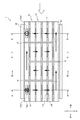
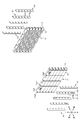
- FIG. 4 It is an overall perspective view of the heat exchanger which shows 1st Embodiment of this invention. It is an exploded perspective view of the flow path forming part.
- A An exploded perspective view of the flow path forming unit seen from the first member side, and (b) an exploded perspective view of the flow path forming unit seen from the second member side. It is a side view of the heat exchanger explaining the flow path of a refrigerant.
- A) is a cross-sectional view taken along the line AA in FIG. 4
- (b) is a cross-sectional view taken along the line BB in FIG. 4
- (c) is a cross-sectional view taken along the line CC in FIG. 4
- (d) is a cross-sectional view taken along the line DD in FIG.
- 1 to 5 show the first embodiment of the present invention.
- the directions are indicated with reference to the front-back direction, the left-right direction (width direction), and the up-down direction indicated by the solid arrows in FIG.
- the heat exchanger 1 of the present invention is provided for each of a plurality of seats provided in the vehicle interior of a vehicle, and blows air as a second fluid whose temperature and humidity are adjusted toward a occupant seated on the seat. It is used in vehicle air conditioners.
- This vehicle air conditioner is equipped with an air conditioner unit in which equipment such as a compressor, a heat exchanger 1, and an expansion valve are integrally formed.
- the air conditioning unit is arranged, for example, at the lower part of the seat, the ceiling of the vehicle interior, the door trim, the lower part of the armrest at the center in the width direction of the vehicle interior, and the like.
- the air supplied from the air conditioning unit into the passenger compartment is blown out from the air outlets provided in the backrest and seat surface of the seat, the lower part of the seat, the ceiling of the passenger compartment, the B pillar of the vehicle, and the like.
- the heat exchanger 1 is used in the air conditioning unit as a condenser for condensing the refrigerant as the first fluid discharged from the compressor and as an evaporator for evaporating the refrigerant decompressed by the expansion valve after flowing out of the condenser. Be done.
- the heat exchanger 1 is a pair of heat exchangers 1 provided at intervals in the width direction, which is a direction orthogonal to the front-rear direction, which is the air flow direction (indicated by the white arrow in FIG. 1).
- a plurality of heat exchange tubes 20 connecting between the flow path forming portion 10 and the pair of flow path forming portions 10, and a plurality of heat exchange tubes 20 provided between the heat exchange tube 20 and the heat exchange tubes 20 and on both outer sides in the vertical direction.
- the heat transfer fins 30 and the pair of covers 40 that cover the heat transfer fins 30 located at the uppermost side from above and the heat transfer fins 30 located at the lowermost side from below are provided.
- Each of the pair of flow path forming portions 10 has a refrigerant flow chamber 10a as a plurality of first fluid flow chambers through which the refrigerant flows.
- a plurality of rows of refrigerant flow chambers 10a in which a plurality of refrigerant flow chambers 10a are arranged in the air flow direction are arranged in a plurality of rows in the vertical direction.
- each of the flow path forming portions 10 constituting the pair of flow path forming portions 10 forms a plurality of refrigerant flow chambers 10a by assembling a plurality of bent plate members.
- each of the pair of flow path forming portions 10 in each of the pair of flow path forming portions 10, six rows in which four refrigerant flow chambers 10a are arranged in the front-rear direction are arranged in the vertical direction, and a total of 24 refrigerant flow chambers 10a are formed. There is.
- the pair of flow path forming units 10 each have a plurality of flow path forming units 11 in which the refrigerant flow chambers 10a are linearly arranged in the front-rear direction and are laminated in the vertical direction.
- the flow path forming unit 11 is provided so as to extend in the front-rear direction, and has a first member 12 located outside in the width direction and a second member 13 located inside in the width direction, and includes the first member 12 and the second member 13. By assembling the second members 13 to each other, a space extending in the front-rear direction is formed.
- the pair of flow path forming portions 10 are each laminated with a pair of closing members 14 that close one end portion and the other end portion in the front-rear direction of the plurality of flow path forming units 11 laminated in the vertical direction.
- Each of the flow path forming units 11 of the above has a plurality of partitioning members 15 for partitioning the refrigerant flow chambers 10a adjacent to each other in the front-rear direction.
- the first member 12 includes a side surface portion 12a extending in the vertical direction, an upper surface portion 12b extending inward in the width direction from the upper end of the side surface portion 12a, and a lower surface extending inward in the width direction from the lower end of the side surface portion 12a. It has a part 12c and.
- the side surface portion 12a is provided with a partition member insertion hole 12a1 for inserting the partition member 15. Further, as shown in FIG. 2, some side surface portions 12a of the plurality of flow path forming units 11 are provided with a refrigerant inflow port 12a2 for allowing the refrigerant to flow into the heat exchanger 1 and a refrigerant from the heat exchanger 1. A refrigerant outlet 12a3 for flowing out is provided.
- the upper surface portion 12b is provided with a refrigerant flow hole 12b1 for communicating the refrigerant flow chamber 10a and the refrigerant flow chamber 10a of the flow path forming unit 11 adjacent to the upper side.
- a claw engaging notch portion 12b2 with which a claw portion described later of the second member 13 engages is provided at an end portion on the inner side in the width direction of the upper surface portion 12b.
- a connecting portion engaging notch portion 12b3 with which a connecting portion described later of the closing member 14 is engaged is provided.
- the lower surface portion 12c is provided with a refrigerant flow hole 12c1 for communicating the refrigerant flow chamber 10a and the refrigerant flow chamber 10a of the flow path forming unit 11 adjacent to the lower side.
- a claw engaging notch portion 12c2 with which a claw portion described later of the second member 13 engages is provided at an end portion on the inner side in the width direction of the lower surface portion 12c.
- a connecting portion engaging notch portion 12c3 with which the connecting portion described later of the closing member 14 is engaged is provided.
- the second member 13 includes a side surface portion 13a extending in the vertical direction, a plurality of upper engaging claw portions 13b extending outward in the width direction from the upper end of the side surface portion 13a, and a plurality of lower portions extending outward in the width direction from the lower end of the side surface portion 13a. It has an engaging claw portion 13c and.
- the side surface portion 13a is provided with a plurality of tube insertion holes 13a1 for inserting the heat exchange tube 20.
- the plurality of upper engaging claws 13b are provided at predetermined intervals, and are engaged with the upper surface of the upper surface portion 12b of the first member 12, and the lower engaging claws of the flow path forming units 11 adjacent to each other upward.
- the upper surface is flat so as to make surface contact with the portion 13c.
- the plurality of lower engaging claws 13c are provided at predetermined intervals, and are engaged with the lower surface of the lower surface portion 12c of the first member 12, and the upper engaging claws of the flow path forming units 11 adjacent to each other below.
- the lower surface is flat so as to make surface contact with the portion 13b.
- a refrigerant flow hole for communicating the refrigerant flow chambers 10a of the flow path forming units 11 adjacent to each other vertically according to the flow path of the refrigerant to be formed. 13b1 and 13c1 are provided. That is, when the refrigerant flow holes 13b1 and 13c1 are not provided, the upper engaging claw portion 13b and the lower engaging claw portion 13c are attached to the first member 12 in a state where the first member 12 and the second member 13 are assembled. The provided refrigerant flow holes 12b1 and 12c1 are closed.
- the upper engaging claw portion 13b and the lower engaging claw portion 13c are attached to the first member 12 in a state where the first member 12 and the second member 13 are assembled when the refrigerant flow holes 13b1 and 13c1 are provided.
- the provided refrigerant flow holes 12b1 and 12c1 are opened.
- the refrigerant flow holes can be closed even when the refrigerant flow holes 12b1 and 12c1 are not provided on the upper surface portion 12b and the lower surface portion 12c of the first member 12.
- Each of the pair of closing members 14 is a plate-shaped member extending in the vertical direction, and the closing portion 14a for closing the opening at the front end portion or the rear end portion of the flow path forming unit 11 and the closing portion 14a adjacent to each other in the vertical direction. It has a connecting portion 14b provided between them.
- the closing member 14 closes the opening of the front end portion or the rear end portion of each flow path forming unit 11 by the closing portion 14a in a state where the plurality of flow path forming units 11 are stacked in the vertical direction.
- Each of the plurality of partition members 15 is a plate-shaped member extending in the vertical direction, and is a connecting portion provided between the partition portion 15a for partitioning the refrigerant flow chambers 10a adjacent to each other in the front-rear direction and the partition portions 15a adjacent to each other in the vertical direction. It has 15b and.
- the partition member 15 has a plurality of flow path forming units 11 stacked in the vertical direction, and by inserting the partition portion 15a into the partition member insertion hole 12a1 of the first member 12, the refrigerant flow chambers 10a adjacent to each other in the front-rear direction To partition.
- the plurality of heat exchange tubes 20 are made of a flat-shaped tube member, and an extruded tube or a plate-shaped member formed by bending a refrigerant flow path or the like is used. Each of the plurality of heat exchange tubes 20 extends in the width direction, and the longitudinal direction of the cross section is directed in the front-rear direction. Further, a plurality of heat exchange tubes 20 are arranged in the front-rear direction in the pair of flow path forming units 11 facing each other in the width direction. In the present embodiment, four heat exchange tubes 20 are connected in the front-rear direction to a pair of flow path forming units 11 facing each other in the width direction.
- the heat transfer fin 30 a corrugated fin or the like obtained by bending a metal plate into a corrugated shape is used.
- the heat transfer fin 30 has a corrugated apex portion formed in a planar shape, and is connected to the heat exchange tube 20 with the apex portion in surface contact.
- the pair of covers 40 are plate-shaped members that extend in the width direction from one flow path forming portion 10 to the other flow path forming portion 10 and have substantially the same dimensions as the heat transfer fins 30 in the front-rear direction. is there.
- the heat exchanger 1 includes a pair of flow path forming portions 10 (first member 12, second member 13, pair of closing members 14, a plurality of partition members 15), a plurality of heat exchange tubes 20, and a plurality of heat transfer fins 30. And, in a state where all the members of the pair of covers 40 are integrally assembled, they are fixed to each other by brazing.
- the heat exchanger 1 configured as described above is formed on a part of the upper engaging claw portion 13b and the lower engaging claw portion 13c of the second member 13 of the flow path forming unit 11.
- the refrigerant flow path is set by providing the refrigerant flow holes 13b1 and 13c1 and providing a partition by the partition member 15 except for a part between the refrigerant flow chambers 10a adjacent to each other in the front-rear direction in the flow path forming unit 11. ..
- the pair of flow path forming units 10 are provided with six flow path forming units 11 in the vertical direction in which four refrigerant flow chambers 10a are arranged in the front-rear direction to form a row. By stacking, a total of 24 refrigerant flow chambers 10a are formed.
- the refrigerant inflow port 12a2 is provided in the refrigerant flow chamber 10a located on the most downstream side and the uppermost side in the air flow direction in one of the flow path forming portions 10.
- a refrigerant outlet 12a3 is provided in the refrigerant flow chamber 10a located on the uppermost flow side and the uppermost side in the air flow direction.
- each refrigerant flow chamber 10a of the second flow path forming unit 11 from the uppermost side and each refrigerant flow chamber 10a of the third flow path forming unit 11 from the uppermost side communicate with each other. Has been done. Further, in one of the flow path forming units 10, each refrigerant flow chamber 10a of the fourth flow path forming unit 11 from the uppermost side and each refrigerant flow chamber 10a of the fifth flow path forming unit 11 from the uppermost side are connected. They are in communication with each other.
- the second refrigerant flow chamber 10a and the third refrigerant flow chamber 10a from the upstream side in the air flow direction of the flow path forming unit 11 located on the uppermost side communicate with each other. ..
- the first refrigerant flow chamber 10a and the second refrigerant flow chamber 10a from the upstream side in the air flow direction of the flow path forming unit 11 located on the lowermost side communicate with each other to provide air.
- the third refrigerant flow chamber 10a and the fourth refrigerant flow chamber 10a communicate with each other from the upstream side in the distribution direction.
- each refrigerant flow chamber 10a of the first flow path forming unit 11 from the uppermost side and each refrigerant flow chamber 10a of the second flow path forming unit 11 from the uppermost side are connected. They are in communication with each other.
- each refrigerant flow chamber 10a of the third flow path forming unit 11 from the uppermost side and each refrigerant flow chamber 10a of the fourth flow path forming unit 11 from the uppermost side are connected. They are in communication with each other.
- each refrigerant flow chamber 10a of the fifth flow path forming unit 11 from the uppermost side and each refrigerant flow chamber 10a of the sixth flow path forming unit 11 from the uppermost side are formed. They are in communication with each other. Further, in the other flow path forming unit 10, the refrigerant flow chambers 10a adjacent to each other in the front-rear direction are partitioned by the partition member 15 in all the flow path forming units 11 in the vertical direction.
- the refrigerant that has flowed into the refrigerant flow chamber 10a located on the most downstream side and the uppermost side in the air flow direction in one flow path forming portion 10 through the refrigerant inflow port 12a2 is on the most downstream side in the air flow direction.
- the refrigerant flow chamber 10a and the heat exchange tube 20 are circulated so as to meander from the uppermost side to the lowermost side.
- the refrigerant that has flowed from the most downstream side in the air flow direction to the lowest side flows into the refrigerant flow chamber 10a located at the second and lowest side from the most downstream side in the air flow direction in one flow path forming portion 10.
- the refrigerant flow chamber 10a and the heat exchange tube 20 are circulated so as to meander from the lowermost side to the uppermost side.
- the refrigerant circulated from the most downstream side in the air flow direction to the uppermost side is sent to the refrigerant flow chamber 10a located on the third and uppermost side in the air flow direction from the most downstream side in one flow path forming portion 10. As shown in FIG. 5C, the refrigerant flowing through the refrigerant flow chamber 10a and the heat exchange tube 20 so as to meander from the uppermost side to the lowermost side.
- the refrigerant that has flowed from the most downstream side in the air flow direction to the bottom side is sent to the refrigerant flow chamber 10a located at the fourth and bottom side from the most downstream side in the air flow direction in one flow path forming portion 10. As shown in FIG. 5D, the refrigerant flows through the refrigerant flow chamber 10a and the heat exchange tube 20 so as to meander from the lowermost side to the uppermost side, and flows out from the refrigerant outlet 12a3.
- a plurality of refrigerant flow chambers 10a provided at intervals in the width direction of the air flow path and through which the refrigerant flows are arranged in the air flow direction.
- the rows of the chambers 10a include a pair of flow path forming portions 10 arranged in a plurality of rows in the vertical direction, and the refrigerant flow chambers 10a facing each other in the pair of flow path forming portions 10 are communicated with each other by the heat exchange tube 20 to provide a refrigerant.
- the flow path is formed by communicating a part of the adjacent refrigerant flow chambers 10a in the flow path forming portion 10 and setting the order in which the refrigerant flows in the plurality of heat exchange tubes 20.
- the flow path forming unit 10 has a plurality of flow path forming units 11 in which a plurality of refrigerant flow chambers 10a are linearly arranged and are laminated in the vertical direction, and the refrigerant flows in the flow path forming units 11 adjacent to each other.
- Refrigerant flow holes 12b1 and 12c1 are formed in the portions communicating with the chambers 10a, respectively, and the partition member 15 is inserted in the portions of the flow path forming unit 11 that partition the adjacent refrigerant flow chambers 10a.
- the closing member 14'that closes both ends of the flow path forming unit 11 in the front-rear direction is a first member 12 on both ends of the flow path forming unit 11 in the front-rear direction, as shown in FIGS. 6 to 8. It is inserted into the closing member insertion hole 12a4 formed in the side surface portion 12a.
- the refrigerant flow chambers 10a adjacent to each other in the front-rear direction are partitioned by the partition member 15 regardless of whether or not they communicate with each other. Further, as shown in FIGS. 6 and 7, a communication hole 15c is provided in the partition portion 15a between the refrigerant flow chambers 10a adjacent to each other in the front-rear direction.
- two refrigerant flow holes 12b1 formed in the upper surface portion 12b of the first member 12 are provided for each refrigerant flow chamber 10a, and two refrigerant flow holes 12c1 formed in the lower surface portion 12c are provided for each refrigerant flow chamber 10a. It is provided.
- a plurality of upper engaging claws 13b are provided at predetermined intervals, respectively, and engage with the upper surface of the upper surface portion 12b of the first member 12, as in the above embodiment. It is provided in. Further, the plurality of lower engaging claw portions 13c are also provided at predetermined intervals as in the above embodiment, and are provided so as to engage with the lower surface of the lower surface portion 12c of the first member 12. ..
- the upper engaging claw portion 13b is fitted between the lower engaging claw portion 13c and the lower engaging claw portion 13c of the flow path forming unit 11 adjacent to the upper side, and is adjacent to the upper part.
- the upper surface is flat so as to make surface contact with the lower surface portion 12c of the first member 12 of the matching flow path forming unit 11.
- the lower engaging claw portion 13c fits between the upper engaging claw portion 13b and the upper engaging claw portion 13b of the flow path forming unit 11 adjacent to the lower side, and the flow path forming unit adjacent to the lower side.
- the lower surface is flat so as to come into surface contact with the upper surface portion 12b of the first member 12 of 11.
- each of the pair of flow path forming portions 10 in each of the pair of flow path forming portions 10, a part of the adjacent refrigerant flow chambers 10a is communicated with each other to the outside. Since it is possible to set the flow path of the refrigerant without increasing the overhanging dimension to, it is possible to save space.
- the upper engaging claw portion 13b is fitted between the lower engaging claw portion 13c and the lower engaging claw portion 13c in the flow path forming unit 11 adjacent to the upper side, and the lower engaging claw portion 13c is downward. It is fitted between the upper engaging claw portion 13b and the upper engaging claw portion 13b in the flow path forming unit 11 adjacent to the above.
- FIG. 9 shows a third embodiment of the present invention.
- the same components as those in the above embodiment are designated by the same reference numerals.
- the upper engaging claw portion 13b and the lower engaging claw portion 13c of the second member 13 have the upper surface portion 12b and the lower surface portion of the first member 12, respectively, as shown in FIG.
- the tip portion extends along the 12c and is curved toward the side surface portion 12a adjacent to the upper surface portion 12b and the lower surface portion 12c.
- each of the pair of flow path forming portions 10 in each of the pair of flow path forming portions 10, a part of the adjacent refrigerant flow chambers 10a is communicated with each other to the outside. Since it is possible to set the flow path of the refrigerant without increasing the overhanging dimension to, it is possible to save space.
- the upper engaging claw portion 13b and the lower engaging claw portion 13c of the second member 13 extend along the upper surface portion 12b and the lower surface portion 12c of the first member 12, respectively, and the tip portion thereof is the upper surface portion of the first member 12. It is curved toward the side surface portion 12a adjacent to the portion 12b and the lower surface portion 12c.
- the heat exchanger of the present invention is applied to an air conditioner for vehicles, but the present invention is not limited to this.
- the present invention can be applied to an air conditioner in a building, a heat exchanger used in a freezing showcase, a refrigerating showcase, and the like.
- the present invention is applied to a heat exchanger that exchanges heat between a refrigerant and air, but the present invention is not limited to this.
- the present invention may be applied to a heat exchanger that exchanges heat between water or antifreeze and air.
- the flow path forming units 11 in which a plurality of refrigerant flow chambers 10a are linearly arranged in the front-rear direction, which is the air flow direction, are laminated in the vertical direction. It is not limited to.
- a flow path forming unit in which a plurality of refrigerant flow chambers are linearly arranged in the vertical direction, which is a direction orthogonal to the air flow direction, may be stacked in the air flow direction.
- the pair of flow path forming portions 10 are arranged at intervals in the width direction, but the present invention is not limited to this.
- the pair of flow path forming portions 10 may be arranged at intervals in the vertical direction.
- the front-rear direction, the width direction, and the vertical direction of the heat exchanger 1 are defined as the flow direction of the air that exchanges heat with the refrigerant from the rear to the front, but the present invention is not limited to this. ..
Landscapes
- Engineering & Computer Science (AREA)
- Physics & Mathematics (AREA)
- Thermal Sciences (AREA)
- Mechanical Engineering (AREA)
- General Engineering & Computer Science (AREA)
- Heat-Exchange Devices With Radiators And Conduit Assemblies (AREA)
- Details Of Heat-Exchange And Heat-Transfer (AREA)
- Air-Conditioning For Vehicles (AREA)
Abstract
省スペース化を図ることができ、限られた設置スペースであっても、高効率な熱交換が可能である熱交換器を提供する。空気の流路の幅方向において互いに間隔をおいて設けられ、冷媒が流通する冷媒流通室10aが、空気の流通方向及び上下方向に複数設けられた一対の流路形成部10を備え、一対の流路形成部10における互いに対向する冷媒流通室10aは、幅方向に延びる熱交換チューブ20によって連通され、冷媒の流通経路は、流路形成部10における隣り合う冷媒流通室10aの一部を連通させて、複数の熱交換チューブ20における冷媒の流通する順序を設定することによって形成される。
Description
本発明は、例えば、空気調和装置に用いられる熱交換器に関するものである。
従来、この種の熱交換器としては、直管部と屈曲部とを有し、蛇行するように延びる伝熱管と、複数の金属板からなり、それぞれ間隔をおいて伝熱管の直管部の外周部に配置されたプレートフィンと、を備えた所謂フィンチューブ式の熱交換器が知られている(例えば、特許文献1参照)。前記熱交換器は、プレートフィンによって伝熱面積を大きくすることで、伝熱管の内側を流通する冷媒と、伝熱管の外側を流通する空気と、を熱交換している。
前記熱交換器は、プレートフィンが配置された複数の直管部を、屈曲部によって連通することによって冷媒の流通経路が形成される。前記熱交換器は、プレートフィンが配置されていない屈曲部における冷媒と空気との熱交換量が小さいが、冷媒の流通抵抗の増大を抑制するため、屈曲部の曲げ半径を大きくする必要がある。
したがって、前記熱交換器は、幅方向の両側に位置する屈曲部の占める範囲が大きく、空気の流通路の幅方向の大きさよりも大きな設置スペースが必要となり、省スペース化を図ることが困難である。
本発明の目的とするところは、省スペース化を図ることができ、限られた設置スペースであっても、高効率な熱交換が可能である熱交換器を提供することにある。
本発明の熱交換器は、前記目的を達成するために、熱交換チューブの内側を流通する第1流体と前記熱交換チューブの外側を流通する第2流体とを熱交換する熱交換器であって、第2流体の流通方向と直交する方向に互いに間隔をおいて設けられ、第1流体が流通する第1流体流通室が第2流体の流通方向に複数配置された前記第1流体流通室の列を、第2流体の流通方向と直交する方向に複数列配置した一対の流路形成部を備え、一対の前記流路形成部における互いに対向する前記第1流体流通室は、前記熱交換チューブによって連通され、第1流体の流通経路は、前記流路形成部における隣り合う第1流体流通室の一部を連通させて、複数の前記熱交換チューブにおける冷媒の流通する順序を設定することによって形成されている。
本発明によれば、一対の流路形成部のそれぞれにおいて、隣り合う第1流体流通室の一部を互いに連通させることによって、外側への張出寸法を大きくすることなく、第1流体の流通経路を設定することが可能となるので、省スペース化を図ることが可能となる。
図1乃至図5は、本発明の第1実施形態を示すものである。尚、本実施形態では、図1の実線の矢印で示す、前後方向、左右方向(幅方向)、上下方向を基準として方向を表記する。
本発明の熱交換器1は、例えば、車両の車室内に設けられた複数のシート毎に設けられ、シートに着座した乗員に向かって温度及び湿度を調整した第2流体としての空気を吹き出させる車両用空気調和装置に用いられるものである。
この車両用空気調和装置は、圧縮機、熱交換器1及び膨張弁等の機器が一体に形成された空調ユニットを備えている。空調ユニットは、例えば、シートの下部、車室の天井部、ドアトリム、車室内の幅方向中央部のアームレストの下部等に配置されている。空調ユニットから車室内に供給される空気は、シートの背もたれや座面、シートの下部、車室の天井部、車両のBピラー等に設けられた吹出口から吹き出される。
熱交換器1は、空調ユニットにおいて、圧縮機から吐出された第1流体としての冷媒を凝縮する凝縮器として、及び、凝縮器から流出した後に膨張弁によって減圧した冷媒を蒸発させる蒸発器として用いられる。
熱交換器1は、図1に示すように、空気の流通方向(図1において白抜き矢印で示す)である前後方向と直交する方向である幅方向に互いに間隔をおいて設けられた一対の流路形成部10と、一対の流路形成部10の間を接続する複数の熱交換チューブ20と、熱交換チューブ20と熱交換チューブ20との間及び上下方向の両外側に設けられた複数の伝熱フィン30と、最も上側に位置する伝熱フィン30を上方から覆うとともに、最も下側に位置する伝熱フィン30を下方から覆う一対のカバー40と、を備えている。
一対の流路形成部10は、それぞれ、冷媒が流通する複数の第1流体流通室としての冷媒流通室10aを有している。一対の流路形成部10には、それぞれ、冷媒流通室10aを空気の流通方向に複数配置した冷媒流通室10aの列が、上下方向に複数列配置されている。本発明において、一対の流路形成部10を構成する各流路形成部10は、折曲形成した複数の板材を組み付けることにより、複数の冷媒流通室10aを構成することが好ましい。図1では、一対の流路形成部10のそれぞれにおいて、4つの冷媒流通室10aを前後方向に配置した列が、上下方向に6つ配置され、合計24個の冷媒流通室10aが形成されている。
具体的に、一対の流路形成部10は、図2に示すように、それぞれ、冷媒流通室10aが前後方向に直線状に並ぶとともに、上下方向に積層された複数の流路形成ユニット11を有している。流路形成ユニット11は、それぞれ前後方向に延びるように設けられ、幅方向外側に位置する第1部材12と、幅方向内側に位置する第2部材13と、を有し、第1部材12及び第2部材13を互いに組み付けることによって前後方向に延びる空間を形成する。さらに、一対の流路形成部10は、それぞれ、上下方向に積層された複数の流路形成ユニット11における前後方向の一端部及び他端部を閉鎖する一対の閉鎖部材14と、積層された複数の流路形成ユニット11のそれぞれにおいて前後に隣り合う冷媒流通室10aを仕切る複数の仕切部材15と、を有している。
第1部材12は、図3に示すように、上下方向に延びる側面部12aと、側面部12aの上端から幅方向内側に延びる上面部12bと、側面部12aの下端から幅方向内側に延びる下面部12cと、を有している。
側面部12aには、仕切部材15を挿入するための仕切部材挿入孔12a1が設けられている。また、複数の流路形成ユニット11における一部の側面部12aには、図2に示すように、熱交換器1に冷媒を流入させるための冷媒流入口12a2と、熱交換器1から冷媒を流出させるための冷媒流出口12a3と、が設けられる。
上面部12bには、図3に示すように、冷媒流通室10aと上方に隣り合う流路形成ユニット11の冷媒流通室10aとを連通するための冷媒流通孔12b1が設けられている。また、上面部12bの幅方向内側の端部には、第2部材13の後述する爪部が係合する爪係合切欠き部12b2が設けられている。さらに、上面部12bの前後方向両側の端部には、閉鎖部材14の後述する連結部が係合する連結部係合切欠き部12b3が設けられている。
下面部12cには、図3に示すように、冷媒流通室10aと下方に隣り合う流路形成ユニット11の冷媒流通室10aとを連通するための冷媒流通孔12c1が設けられている。また、下面部12cの幅方向内側の端部には、第2部材13の後述する爪部が係合する爪係合切欠き部12c2が設けられている。さらに、下面部12cの前後方向両側の端部には、閉鎖部材14の後述する連結部が係合する連結部係合切欠き部12c3が設けられている。
第2部材13は、上下方向に延びる側面部13aと、側面部13aの上端から幅方向外側に延びる複数の上部係合爪部13bと、側面部13aの下端から幅方向外側に延びる複数の下部係合爪部13cと、を有している。
側面部13aには、熱交換チューブ20を挿入するための複数のチューブ挿入孔13a1が設けられている。
複数の上部係合爪部13bは、それぞれ所定の間隔をおいて設けられ、第1部材12の上面部12bの上面に係合するとともに、上方に隣り合う流路形成ユニット11の下部係合爪部13cと面接触するように上面が平面を成している。
複数の下部係合爪部13cは、それぞれ所定の間隔をおいて設けられ、第1部材12の下面部12cの下面に係合するとともに、下方に隣り合う流路形成ユニット11の上部係合爪部13bと面接触するように下面が平面を成している。
上下方向に隣り合う流路形成ユニット11の間には、上側の第1部材12の下面部12c、上側の第2部材13の下部係合爪部13c、下側の第2部材13の上部係合爪部13b及び下側の第1部材12の上面部12bの四つの部材が介在することになる。
また、上部係合爪部13b及び下部係合爪部13cには、形成する冷媒の流通経路に応じて、上下に隣り合う流路形成ユニット11の冷媒流通室10aを連通するための冷媒流通孔13b1,13c1が設けられる。即ち、上部係合爪部13b及び下部係合爪部13cは、冷媒流通孔13b1,13c1が設けられていない場合に、第1部材12及び第2部材13を組み付けた状態で第1部材12に設けられた冷媒流通孔12b1,12c1を閉鎖する。また、上部係合爪部13b及び下部係合爪部13cは、冷媒流通孔13b1,13c1が設けられている場合に、第1部材12及び第2部材13を組み付けた状態で第1部材12に設けられた冷媒流通孔12b1,12c1を開放する。同様に、第1部材12の上面部12b及び下面部12cに冷媒流通孔12b1,12c1が設けられていない場合でも冷媒流通孔を閉鎖することができる。
一対の閉鎖部材14は、それぞれ、上下方向に延びる板状の部材であり、流路形成ユニット11の前端部または後端部の開口を閉鎖する閉鎖部14aと、上下に隣り合う閉鎖部14aの間に設けられた連結部14bと、を有している。閉鎖部材14は、複数の流路形成ユニット11を上下方向に積層した状態で、それぞれの流路形成ユニット11の前端部または後端部の開口を閉鎖部14aによって閉鎖する。
複数の仕切部材15は、それぞれ、上下方向に延びる板状の部材であり、前後に隣り合う冷媒流通室10aを仕切る仕切部15aと、上下に隣り合う仕切部15aの間に設けられた連結部15bと、を有している。仕切部材15は、複数の流路形成ユニット11を上下方向に積層した状態で、第1部材12の仕切部材挿入孔12a1に仕切部15aを挿入することにより、前後方向に隣り合う冷媒流通室10aを仕切る。
複数の熱交換チューブ20は、扁平形状の管部材からなり、押出チューブ、あるいは板状の部材を折り曲げて冷媒流路を形成したもの等が用いられる。複数の熱交換チューブ20は、それぞれ、幅方向に延びるとともに、横断面の長手方向が前後方向に向けられている。また、互いに幅方向に対向する一対の流路形成ユニット11には、複数の熱交換チューブ20が前後方向に配置されている。本実施形態では、互いに幅方向に対向する一対の流路形成ユニット11に対して前後方向に4本の熱交換チューブ20が接続されている。
伝熱フィン30は、金属板を波形に屈曲したコルゲートフィン等が用いられる。伝熱フィン30は、波形の頂点部分が面状に形成され、熱交換チューブ20に頂点部分が面接触した状態で接続されている。
一対のカバー40は、それぞれ、一方の流路形成部10から他方の流路形成部10にわたって幅方向に延びるとともに、伝熱フィン30の前後方向の寸法と略同一の寸法を有する板状部材である。
熱交換器1は、一対の流路形成部10(第1部材12、第2部材13、一対の閉鎖部材14、複数の仕切部材15)、複数の熱交換チューブ20、複数の伝熱フィン30及び一対のカバー40の全ての部材を一体に組み付けた状態で、互いにロウ付けによって固定することで製造される。
以上のように構成された熱交換器1は、一対の流路形成部10において、流路形成ユニット11の第2部材13の上部係合爪部13b及び下部係合爪部13cの一部に冷媒流通孔13b1,13c1を設け、仕切部材15によって流路形成ユニット11における前後方向に隣り合う冷媒流通室10aの間の一部を除いて仕切りを設けることによって、冷媒の流通経路が設定される。
ここで、一対の流路形成部10には、図4に示すように、それぞれ、4つの冷媒流通室10aを前後方向に配置して列を成す流路形成ユニット11を、上下方向に6段積層することによって、合計24個の冷媒流通室10aが形成されている。
また、一方の流路形成部10における、空気流通方向の最下流側に位置すると共に最上部側に位置する冷媒流通室10aには、冷媒流入口12a2が設けられている。空気流通方向の最上流側に位置するとともに最上部側に位置する冷媒流通室10aには、冷媒流出口12a3が設けられている。
一方の流路形成部10では、最上部側から2番目の流路形成ユニット11の各冷媒流通室10aと最上部側から3番目の流路形成ユニット11の各冷媒流通室10aとが互いに連通されている。また、一方の流路形成部10では、最上部側から4番目の流路形成ユニット11の各冷媒流通室10aと最上部側から5番目の流路形成ユニット11の各冷媒流通室10aとが互いに連通されている。さらに、一方の流路形成部10では、最上部側に位置する流路形成ユニット11の空気流通方向上流側から2番目の冷媒流通室10aと3番目の冷媒流通室10aとが連通している。また、一方の流路形成部10では、最下部側に位置する流路形成ユニット11の空気流通方向上流側から1番目の冷媒流通室10aと2番目の冷媒流通室10aとが連通し、空気流通方向上流側から3番目の冷媒流通室10aと4番目の冷媒流通室10aとが連通している。
また、他方の流路形成部10では、最上部側から1番目の流路形成ユニット11の各冷媒流通室10aと最上部側から2番目の流路形成ユニット11の各冷媒流通室10aとが互いに連通されている。また、他方の流路形成部10では、最上部側から3番目の流路形成ユニット11の各冷媒流通室10aと最上部側から4番目の流路形成ユニット11の各冷媒流通室10aとが互いに連通されている。さらに、他方の流路形成部10では、最上部側から5番目の流路形成ユニット11の各冷媒流通室10aと最上部側から6番目の流路形成ユニット11の各冷媒流通室10aとが互いに連通されている。また、他方の流路形成部10では、上下方向の全ての流路形成ユニット11において、前後方向に隣り合う冷媒流通室10aが仕切部材15によって仕切られている。
これにより、冷媒流入口12a2を介して一方の流路形成部10における空気流通方向の最下流側且つ最上部側に位置する冷媒流通室10aに流入した冷媒は、空気流通方向の最下流側において、図5(a)に示すように、最上部側から最下部側に向かって蛇行するように、冷媒流通室10a及び熱交換チューブ20を流通する。
空気流通方向の最下流側を最下部側まで流通した冷媒は、一方の流路形成部10における空気流通方向の最下流側から2番目且つ最下部側に位置する冷媒流通室10aに流入し、図5(b)に示すように、最下部側から最上部側に向かって蛇行するように、冷媒流通室10a及び熱交換チューブ20を流通する。
空気流通方向の最下流側から2番目を最上部側まで流通した冷媒は、一方の流路形成部10における空気流通方向の最下流側から3番目且つ最上部側に位置する冷媒流通室10aに流入し、図5(c)に示すように、最上部側から最下部側に向かって蛇行するように、冷媒流通室10a及び熱交換チューブ20を流通する。
空気流通方向の最下流側から3番目を最下部側まで流通した冷媒は、一方の流路形成部10における空気流通方向の最下流側から4番目且つ最下部側に位置する冷媒流通室10aに流入し、図5(d)に示すように、最下部側から最上部側に向かって蛇行するように、冷媒流通室10a及び熱交換チューブ20を流通し、冷媒流出口12a3から流出する。
このように、本実施形態の熱交換器によれば、空気の流路の幅方向において互いに間隔をおいて設けられ、冷媒が流通する冷媒流通室10aを空気の流通方向に複数配置した冷媒流通室10aの列が、上下方向に複数列配置された一対の流路形成部10を備え、一対の流路形成部10における互いに対向する冷媒流通室10aが、熱交換チューブ20によって連通され、冷媒の流通経路が、流路形成部10における隣り合う冷媒流通室10aの一部を連通させて、複数の熱交換チューブ20における冷媒の流通する順序を設定することによって形成される。
これにより、一対の流路形成部10のそれぞれにおいて、隣り合う冷媒流通室10aの一部を互いに連通させることによって、外側への張出寸法を大きくすることなく、冷媒の流通経路を設定することが可能となるので、省スペース化を図ることが可能となる。
また、流路形成部10は、複数の冷媒流通室10aが直線状に並ぶとともに、上下方向に積層される複数の流路形成ユニット11を有し、互いに隣り合う流路形成ユニット11における冷媒流通室10aを連通する部分には、それぞれ冷媒流通孔12b1,12c1が形成され、流路形成ユニット11における隣り合う冷媒流通室10aを仕切る部分には、仕切部材15が挿入される。
これにより、流路形成ユニット11の積層数を変更することによって、熱交換器1の設置スペースに合わせた熱交換器1、必要な熱交換の性能を満たす熱交換器1を形成することが可能となる。
図6乃至図8は、本発明の第2実施形態を示すものである。尚、前記実施形態と同様の構成部分には、同一の符号を付して示す。
本実施形態において、流路形成ユニット11の前後方向両端部を閉鎖する閉鎖部材14´は、図6乃至図8に示すように、流路形成ユニット11の前後方向両端側における第1部材12の側面部12aに形成された閉鎖部材挿入孔12a4に挿入されるようになっている。
また、流路形成ユニット11は、互いに連通するか否かにかかわらず前後方向に隣り合う冷媒流通室10aが仕切部材15によって仕切られている。さらに、互いに連通する前後方向に隣り合う冷媒流通室10aの間の仕切部15aには、図6及び図7に示すように、連通孔15cが設けられている。
また、第1部材12の上面部12bに形成される冷媒流通孔12b1が冷媒流通室10a毎に2つ設けられ、下面部12cに形成される冷媒流通孔12c1が冷媒流通室10a毎に2つ設けられている。
また、第2部材13は、前記実施形態と同様に、複数の上部係合爪部13bが、それぞれ所定の間隔をおいて設けられ、第1部材12の上面部12bの上面に係合するように設けられている。また、複数の下部係合爪部13cについても、前記実施形態と同様に、それぞれ所定の間隔をおいて設けられ、第1部材12の下面部12cの下面に係合するように設けられている。
さらに、本実施形態では、上部係合爪部13bが、上方に隣り合う流路形成ユニット11の下部係合爪部13cと下部係合爪部13cとの間に嵌合するとともに、上方に隣り合う流路形成ユニット11の第1部材12の下面部12cに面接触するように上面が平面を成している。また、下部係合爪部13cが、下方に隣り合う流路形成ユニット11の上部係合爪部13bと上部係合爪部13bとの間に嵌合するとともに、下方に隣り合う流路形成ユニット11の第1部材12の上面部12bに面接触するように下面が平面を成している。
上下方向に隣り合う流路形成ユニット11の間には、上側の第1部材12の下面部12c、上側の第2部材13の下部係合爪部13cまたは下側の第2部材13の上部係合爪部13b、下側の第1部材12の上面部12bの三つの部材が介在することになる。
このように、本実施形態の熱交換器によれば、前記実施形態と同様に、一対の流路形成部10のそれぞれにおいて、隣り合う冷媒流通室10aの一部を互いに連通させることによって、外側への張出寸法を大きくすることなく、冷媒の流通経路を設定することが可能となるので、省スペース化を図ることが可能となる。
また、上部係合爪部13bは、上方に隣り合う流路形成ユニット11における下部係合爪部13cと下部係合爪部13cとの間に嵌合し、下部係合爪部13cは、下方に隣り合う流路形成ユニット11における上部係合爪部13bと上部係合爪部13bとの間に嵌合する。
これにより、熱交換器1を組付ける際に、積層する流路形成ユニット11の位置決めが可能となり、熱交換器1の組付け精度の向上を図ることが可能となる。また、上下方向に隣り合う流路形成ユニット11の間に介在する部材数を少なくすることができるので、流路形成ユニット11を積層する方向における大きさについて、小型化を図ることが可能となる。
図9は、本発明の第3実施形態を示すものである。尚、前記実施形態と同様の構成部分には、同一の符号を付して示す。
本実施形態の流路形成ユニット11は、第2部材13の上部係合爪部13b及び下部係合爪部13cが、図9に示すように、それぞれ第1部材12における上面部12b及び下面部12cに沿って延びるとともに、先端部が上面部12b及び下面部12cと隣り合う側面部12aに向かって湾曲している。
このように、本実施形態の熱交換器によれば、前記実施形態と同様に、一対の流路形成部10のそれぞれにおいて、隣り合う冷媒流通室10aの一部を互いに連通させることによって、外側への張出寸法を大きくすることなく、冷媒の流通経路を設定することが可能となるので、省スペース化を図ることが可能となる。
また、第2部材13の上部係合爪部13b及び下部係合爪部13cは、それぞれ第1部材12における上面部12b及び下面部12cに沿って延びるとともに、先端部が第1部材12における上面部12b及び下面部12cと隣り合う側面部12aに向かって湾曲している。
これにより、熱交換器1を組み付ける際に、第1部材12に対して第2部材13の組付け状態を保持することが可能となるので、熱交換器1の組付け精度を向上させることが可能となる。
尚、前記実施形態では、本発明の熱交換器を車両用空気調和装置に適用したものを示したが、これに限られるものではない。例えば、建物の室内の空気調和装置や、冷凍ショーケース及び冷蔵ショーケース等に用いられる熱交換器に、本発明を適用することが可能である。
また、前記実施形態では、冷媒と空気とを熱交換する熱交換器に対して本発明を適用したものを示したが、これに限られるものではない。例えば、水や不凍液と空気とを熱交換する熱交換器に本発明を適用してもよい。
また、前記実施形態では、空気の流通方向である前後方向に複数の冷媒流通室10aが直線状に配置された流路形成ユニット11を上下方向に積層するようにしたものを示したが、これに限られるものではない。空気の流通方向に直交する方向である上下方向に複数の冷媒流通室が直線状に配置された流路形成ユニットを空気の流通方向に積層するようにしてもよい。
また、前記実施形態では、一対の流路形成部10を幅方向に互いに間隔をおいて配置したものを示したが、これに限られるものではない。一対の流路形成部10を上下方向に互いに間隔をおいて配置してもよい。
また、前記実施形態では、冷媒と熱交換する空気の流通方向を後方から前方に向かう向きとして、熱交換器1の前後方向、幅方向及び上下方向を定義したが、これに限られるものではない。例えば、空気の流通方向を下方から上方に向かう向きとして熱交換器1を配置し、熱交換器1の前後方向、幅方向及び上下方向を定義することも可能である。
1…熱交換器、10…流路形成部、10a…冷媒流通室、11…流路形成ユニット、12…第1部材、12a…側面部、12b…上面部、12c…下面部、13…第2部材、13a…側面部、13b…上部係合爪部、13c…下部係合爪部、14,14´…閉鎖部材、15…仕切部材、15c…連通孔、20…熱交換チューブ。
Claims (4)
- 熱交換チューブの内側を流通する第1流体と前記熱交換チューブの外側を流通する第2流体とを熱交換する熱交換器であって、
第2流体の流通方向と直交する方向に互いに間隔をおいて設けられ、第1流体が流通する第1流体流通室が第2流体の流通方向に複数配置された前記第1流体流通室の列を、第2流体の流通方向と直交する方向に複数列配置した一対の流路形成部を備え、
一対の前記流路形成部における互いに対向する前記第1流体流通室は、前記熱交換チューブによって連通され、
第1流体の流通経路は、前記流路形成部における隣り合う第1流体流通室の一部を連通させて、複数の前記熱交換チューブにおける冷媒の流通する順序を設定することによって形成される
熱交換器。 - 前記流路形成部は、複数の前記第1流体流通室が直線状に並ぶとともに、積層される複数の流路形成ユニットを有し、
互いに隣り合う前記流路形成ユニットにおける前記第1流体流通室を連通する部分には、それぞれ冷媒流通孔が形成され、
前記流路形成ユニットにおける隣り合う前記第1流体流通室を仕切る部分には、仕切部材が挿入される
請求項1に記載の熱交換器。 - 前記流路形成ユニットは、第1部材と、前記第1部材における隣り合う前記流路形成ユニットと対向する平面に係合する複数の係合爪部が複数の前記第1流体流通室の並ぶ方向に間隔をおいて形成された第2部材と、を有し、
前記係合爪部は、隣り合う前記流路形成ユニットの前記第2部材における係合爪部と係合爪部との間に嵌合する
請求項2に記載の熱交換器。 - 前記係合爪部は、前記第1部材における前記平面に沿って延びるとともに、先端部が前記第1部材における前記平面と隣り合う面に向かって湾曲している
請求項3に記載の熱交換器。
Priority Applications (1)
| Application Number | Priority Date | Filing Date | Title |
|---|---|---|---|
| CN202080020220.4A CN113557396B (zh) | 2019-03-20 | 2020-03-12 | 热交换器 |
Applications Claiming Priority (2)
| Application Number | Priority Date | Filing Date | Title |
|---|---|---|---|
| JP2019053547A JP7263072B2 (ja) | 2019-03-20 | 2019-03-20 | 熱交換器 |
| JP2019-053547 | 2019-03-20 |
Publications (1)
| Publication Number | Publication Date |
|---|---|
| WO2020189490A1 true WO2020189490A1 (ja) | 2020-09-24 |
Family
ID=72519806
Family Applications (1)
| Application Number | Title | Priority Date | Filing Date |
|---|---|---|---|
| PCT/JP2020/010780 Ceased WO2020189490A1 (ja) | 2019-03-20 | 2020-03-12 | 熱交換器 |
Country Status (3)
| Country | Link |
|---|---|
| JP (1) | JP7263072B2 (ja) |
| CN (1) | CN113557396B (ja) |
| WO (1) | WO2020189490A1 (ja) |
Cited By (3)
| Publication number | Priority date | Publication date | Assignee | Title |
|---|---|---|---|---|
| WO2022045094A1 (ja) * | 2020-08-25 | 2022-03-03 | サンデン・アドバンストテクノロジー株式会社 | 熱交換器 |
| CN114777324A (zh) * | 2022-04-12 | 2022-07-22 | 安徽美博新能源科技有限公司 | 一种空调冷凝管的辅助安装装置 |
| WO2022185817A1 (ja) * | 2021-03-04 | 2022-09-09 | 株式会社デンソー | 熱交換器 |
Citations (4)
| Publication number | Priority date | Publication date | Assignee | Title |
|---|---|---|---|---|
| US1539267A (en) * | 1923-03-29 | 1925-05-26 | Schutte & Koerting Co | Heat-exchange apparatus |
| GB2078361A (en) * | 1980-06-24 | 1982-01-06 | Delanair Ltd | Heat exchangers and heat exchanger headers |
| US5303770A (en) * | 1993-06-04 | 1994-04-19 | Dierbeck Robert F | Modular heat exchanger |
| ES2332619A1 (es) * | 2006-06-15 | 2010-02-09 | Hrs Spiratube, S.L. | Intercambiador de calor de carcasa y tubos compacto. |
Family Cites Families (10)
| Publication number | Priority date | Publication date | Assignee | Title |
|---|---|---|---|---|
| JP2002205230A (ja) * | 2000-12-28 | 2002-07-23 | Calsonic Kansei Corp | ヘッダー仮保持装置 |
| JP5002797B2 (ja) * | 2007-03-16 | 2012-08-15 | 株式会社ケーヒン・サーマル・テクノロジー | 熱交換器 |
| JP5002798B2 (ja) * | 2007-04-16 | 2012-08-15 | 株式会社ケーヒン・サーマル・テクノロジー | 熱交換器 |
| WO2013160954A1 (ja) * | 2012-04-26 | 2013-10-31 | 三菱電機株式会社 | 熱交換器及びこの熱交換器を備えた冷凍サイクル装置 |
| JP2013257095A (ja) * | 2012-06-13 | 2013-12-26 | Sanden Corp | フィンレス熱交換器 |
| JP5920167B2 (ja) * | 2012-10-17 | 2016-05-18 | 株式会社デンソー | 熱交換器 |
| KR102122257B1 (ko) * | 2013-12-24 | 2020-06-26 | 엘지전자 주식회사 | 열교환기 |
| JP6234321B2 (ja) * | 2014-05-16 | 2017-11-22 | 三菱電機株式会社 | 熱交換器の製造装置 |
| JP6274709B2 (ja) * | 2016-01-21 | 2018-02-07 | 株式会社Uacj | 熱交換器用ヒートシンク及び該ヒートシンクを備えた熱交換器 |
| JP2018071895A (ja) * | 2016-10-31 | 2018-05-10 | パナソニックIpマネジメント株式会社 | 熱交換器 |
-
2019
- 2019-03-20 JP JP2019053547A patent/JP7263072B2/ja active Active
-
2020
- 2020-03-12 CN CN202080020220.4A patent/CN113557396B/zh active Active
- 2020-03-12 WO PCT/JP2020/010780 patent/WO2020189490A1/ja not_active Ceased
Patent Citations (4)
| Publication number | Priority date | Publication date | Assignee | Title |
|---|---|---|---|---|
| US1539267A (en) * | 1923-03-29 | 1925-05-26 | Schutte & Koerting Co | Heat-exchange apparatus |
| GB2078361A (en) * | 1980-06-24 | 1982-01-06 | Delanair Ltd | Heat exchangers and heat exchanger headers |
| US5303770A (en) * | 1993-06-04 | 1994-04-19 | Dierbeck Robert F | Modular heat exchanger |
| ES2332619A1 (es) * | 2006-06-15 | 2010-02-09 | Hrs Spiratube, S.L. | Intercambiador de calor de carcasa y tubos compacto. |
Cited By (5)
| Publication number | Priority date | Publication date | Assignee | Title |
|---|---|---|---|---|
| WO2022045094A1 (ja) * | 2020-08-25 | 2022-03-03 | サンデン・アドバンストテクノロジー株式会社 | 熱交換器 |
| US12578146B2 (en) | 2020-08-25 | 2026-03-17 | Sanden Corporation | Heat exchanger |
| WO2022185817A1 (ja) * | 2021-03-04 | 2022-09-09 | 株式会社デンソー | 熱交換器 |
| CN114777324A (zh) * | 2022-04-12 | 2022-07-22 | 安徽美博新能源科技有限公司 | 一种空调冷凝管的辅助安装装置 |
| CN114777324B (zh) * | 2022-04-12 | 2023-12-26 | 安徽美博新能源科技有限公司 | 一种空调冷凝管的辅助安装装置 |
Also Published As
| Publication number | Publication date |
|---|---|
| JP7263072B2 (ja) | 2023-04-24 |
| CN113557396A (zh) | 2021-10-26 |
| CN113557396B (zh) | 2023-06-27 |
| JP2020153605A (ja) | 2020-09-24 |
Similar Documents
| Publication | Publication Date | Title |
|---|---|---|
| CN104121727B (zh) | 蒸发器及使用该蒸发器的车辆用空调装置 | |
| CN107816824B (zh) | 热交换器 | |
| US9366463B2 (en) | Evaporator | |
| CN104121728B (zh) | 蒸发器及使用该蒸发器的车辆用空调装置 | |
| JP6310386B2 (ja) | 熱交換器、当該熱交換器を備えたハウジングおよび空気調和回路 | |
| JP5002797B2 (ja) | 熱交換器 | |
| US9163881B2 (en) | Heat exchanger | |
| US20130299150A1 (en) | Heat Exchanger For A Motor Vehicle | |
| JP5408951B2 (ja) | 冷媒蒸発器およびそれを用いた空調装置 | |
| CN113557396B (zh) | 热交换器 | |
| JP5875918B2 (ja) | 車室内熱交換器及び車室内熱交換器のヘッダ間接続部材 | |
| CN113939705A (zh) | 热交换器 | |
| JP4945399B2 (ja) | 熱交換器 | |
| JP5990402B2 (ja) | 熱交換器 | |
| JP6415204B2 (ja) | エバポレータおよびこれを用いた車両用空調装置 | |
| US20150328950A1 (en) | Light weight hvac module | |
| JP2021014943A (ja) | 熱交換器 | |
| KR100640068B1 (ko) | 일체형 열교환기 | |
| WO2020066393A1 (ja) | 熱交換器 | |
| JP2006505759A (ja) | 自動車用のマルチ通路熱交換器 | |
| WO2020066394A1 (ja) | 熱交換器 | |
| WO2020189488A1 (ja) | 温度調節装置 | |
| WO2020059416A1 (ja) | 熱交換器 | |
| KR20240165744A (ko) | 자동차용 열교환기 | |
| JP2021050828A (ja) | 熱交換器 |
Legal Events
| Date | Code | Title | Description |
|---|---|---|---|
| 121 | Ep: the epo has been informed by wipo that ep was designated in this application |
Ref document number: 20774532 Country of ref document: EP Kind code of ref document: A1 |
|
| NENP | Non-entry into the national phase |
Ref country code: DE |
|
| 122 | Ep: pct application non-entry in european phase |
Ref document number: 20774532 Country of ref document: EP Kind code of ref document: A1 |