WO2020189425A1 - ランキンサイクルシステム及びその制御方法 - Google Patents
ランキンサイクルシステム及びその制御方法 Download PDFInfo
- Publication number
- WO2020189425A1 WO2020189425A1 PCT/JP2020/010415 JP2020010415W WO2020189425A1 WO 2020189425 A1 WO2020189425 A1 WO 2020189425A1 JP 2020010415 W JP2020010415 W JP 2020010415W WO 2020189425 A1 WO2020189425 A1 WO 2020189425A1
- Authority
- WO
- WIPO (PCT)
- Prior art keywords
- flow path
- working fluid
- condenser
- liquid state
- storage unit
- Prior art date
- Legal status (The legal status is an assumption and is not a legal conclusion. Google has not performed a legal analysis and makes no representation as to the accuracy of the status listed.)
- Ceased
Links
Images

Classifications
-
- F—MECHANICAL ENGINEERING; LIGHTING; HEATING; WEAPONS; BLASTING
- F01—MACHINES OR ENGINES IN GENERAL; ENGINE PLANTS IN GENERAL; STEAM ENGINES
- F01K—STEAM ENGINE PLANTS; STEAM ACCUMULATORS; ENGINE PLANTS NOT OTHERWISE PROVIDED FOR; ENGINES USING SPECIAL WORKING FLUIDS OR CYCLES
- F01K25/00—Plants or engines characterised by use of special working fluids, not otherwise provided for; Plants operating in closed cycles and not otherwise provided for
- F01K25/08—Plants or engines characterised by use of special working fluids, not otherwise provided for; Plants operating in closed cycles and not otherwise provided for using special vapours
- F01K25/10—Plants or engines characterised by use of special working fluids, not otherwise provided for; Plants operating in closed cycles and not otherwise provided for using special vapours the vapours being cold, e.g. ammonia, carbon dioxide, ether
Definitions
- This disclosure relates to the Rankine cycle system and its control method.
- a condensed water tank for storing the condensed water (condensate) generated in the refrigerant pipe is provided in the refrigerant pipe near the outlet of the turbine (expansor), and the condensed water stored in the condensed water tank is steamed by a heating device.
- a waste heat recovery device (Rankine cycle system for vehicles) that returns the water to a condenser (condenser) has been proposed (see, for example, Patent Document 1).
- the present disclosure is to provide a Rankine cycle system and a control method thereof that can process the condensate stored in the flow path between the outlet of the expander and the inlet of the condenser with energy saving.
- the Rankin cycle system of the embodiment of the present disclosure for achieving the above object includes a flow path for circulating a working fluid, an expander arranged in the flow path for expanding the working fluid, and a downstream side of the expander.
- a condenser whose inlet is arranged higher than the outlet of the expander to condense the working fluid, and a condenser downstream of the condenser and upstream of the expander.
- a Rankin cycle system configured to include a circulation device arranged in the flow path of the above to pump the working fluid, the first flow path between the outlet of the inflator and the inlet of the condenser.
- a bypass that is arranged in the flow path and communicates the storage section that stores the working fluid in a liquid state and the second flow path that is the flow path between the outlet of the condenser and the inlet of the circulation device and the storage section.
- a liquid level estimation device for estimating the liquid level of the working fluid in a state and a control device for controlling the Rankin cycle system are provided, and the control device is based on the liquid level estimated by the liquid level estimation device.
- the transfer device is controlled. Then, it is configured to control the transfer of the working fluid in the liquid state from the storage unit to the second flow path.
- control method of the Rankin cycle system includes a flow path for circulating a working fluid, an expander arranged in the flow path for expanding the working fluid, and the above.
- a condenser that is arranged in the flow path on the downstream side of the inflator and whose inlet is arranged at a position higher than the outlet of the inflator to condense the working fluid, and a condenser that is downstream of the condenser and said. It is arranged in the circulation device which is arranged in the flow path on the upstream side of the inflator and pumps the working fluid, and in the first flow path which is the flow path between the outlet of the inflator and the inlet of the condenser.
- the storage section for storing the working fluid in a liquid state
- the bypass flow path for communicating the second flow path and the storage section, which is the flow path between the outlet of the condenser and the inlet of the circulation device, and the bypass.
- a control method of a Rankin cycle system which is arranged in a flow path and is provided with a transfer device for transferring the working fluid in a liquid state from the storage unit to the second flow path as needed. Based on the first step of estimating the liquid level of the working fluid in the liquid state stored in the storage unit and the liquid level of the working fluid in the liquid state estimated in the first step, the storage unit.
- the method is characterized by having a third step of controlling the transfer device to transfer the working fluid in the liquid state from the storage unit to the second flow path.
- the condensate stored in the flow path between the outlet of the expander and the inlet of the condenser can be treated with energy saving.
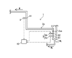
- FIG. 1 is a diagram illustrating the Rankine cycle system of the present embodiment.
- FIG. 2 is an enlarged view of the flow path for the working fluid between the expander and the condenser of FIG.
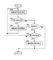
- FIG. 3 is a diagram illustrating a control method of the Rankine cycle system of the present embodiment in the form of a control flow.
- the Rankine cycle system 1 of the present embodiment has a tank 3, a pump (circulator) 4, an evaporator 5, and an expander in a flow path (flow path) 2 for a working fluid. It is a system including 6 and a condenser 7.
- the flow path 2 for the working fluid is a closed flow path for circulating the working fluid W.
- the tank 3 is arranged in the flow path 2 for the working fluid and stores the working fluid W.
- the pump 4 is arranged in the flow path 2 for the working fluid on the downstream side of the tank 3 and on the upstream side of the evaporator 5 and the expander 6, and pumps the working fluid W. When the working fluid W is pumped by the pump 4, the working fluid W circulates in the flow path 2 for the working fluid.
- the evaporator 5 is arranged in the flow path 2 for the working fluid on the downstream side of the pump 4, and heats and evaporates the working fluid W by exchanging heat with the exhaust G of the engine (internal combustion engine).
- the inflator 6 is arranged in the flow path 2 for the working fluid on the downstream side of the evaporator 5 to expand the working fluid W.
- a drive device (engine, motor, etc.) is connected to the output shaft 6a of the expander 6 via a disconnection device (clutch, etc.), and is generated in the output shaft 6a due to expansion of the working fluid W when the disconnection device is connected. The generated power is transmitted to the drive device.
- the condenser 7 is arranged in the flow path 2 for the working fluid on the downstream side of the expander 6 to condense the working fluid W.
- the inlet 7a of the condenser 7 is located higher than the outlet 6b of the expander 6.
- the outlet 7b of the condenser 7 is arranged higher than the inlet 3a of the tank 3.
- the flow path between the outlet 6b of the expander 6 and the inlet 7a of the condenser 7 is referred to as a first flow path 2a.
- a U-shaped tube-shaped storage portion 2aa is formed directly below the outlet 6b of the inflator 6.
- a working fluid in a gaseous state flows through the first flow path 2a, but a condensed liquid WL which is a working fluid in a liquid state may be generated.
- This condensate WL is stored in the storage unit 2aa.
- the liquid level (liquid level) LS of the condensate WL increases.
- the shape of the storage portion 2aa is not limited to the U-shaped tube shape as long as it can store the condensate WL.
- the flow path between the outlet 7b of the condenser 7 and the inlet of the pump 4 is referred to as a second flow path 2b.
- a liquid working fluid flows through the second flow path 2b.
- a pressure sensor 8 for acquiring the pressure of the working fluid W passing through the first flow path 2a is arranged in the first flow path 2a. Since the pressure of the working fluid W hardly changes in the first flow path 2a, the position of the pressure sensor 8 may be any position in the first flow path 2a where there is no possibility that the condensate WL is generated. In the present embodiment, the pressure sensor 8 is arranged at the position A1 of the first flow path 2a on the downstream side of the storage portion 2aa.
- a plurality of (two in this embodiment) temperature sensors 9 (9a, 9b) are arranged at intervals of each in the storage portion 2aa of the first flow path 2a.
- the temperature sensor 9a is arranged at the position B1 in the storage unit 2aa.
- the temperature sensor 9b is arranged at the position B2 on the downstream side of the position B1 in the storage unit 2aa.
- Position B2 is higher than position B1.
- the liquid level LS of the condensate WL rises in the direction from the position B1 to the position B2 as the amount of the condensate WL stored in the storage portion 2aa increases.
- the Rankine cycle system 1 of the present embodiment is provided with a liquid level estimation device 10.
- the liquid level estimation device 10 estimates the liquid level LS of the condensate WL stored in the storage unit 2aa based on the acquired value of the pressure sensor 8 and the acquired value of the temperature sensor 9.
- the liquid level estimation device 10 is composed of a CPU (Central Processing Unit) that performs various information processing, an internal storage device that can read and write programs and information processing results used for performing various information processing, and various interfaces. It is hardware.
- the liquid level acquisition device 10 may be configured as a separate body from the control device 13 described later, or may be incorporated as a part of the control device 13.
- the liquid level estimation device 10 determines the phase state of the working fluid W at the installation position B1 (B2) of the corresponding temperature sensor 9a (9b). Estimate the gas or liquid state).
- the liquid level estimation device 10 estimates that the liquid level LS of the condensate WL is at the position of the first flow path 2a lower than the position B1.
- the liquid level estimation device 10 has the liquid level LS of the condensate WL.
- the liquid level estimation device 10 estimates that the liquid level LS of the condensate WL is at the position of the first flow path 2a higher than the position B2. To do.
- the Rankine cycle system 1 of the present embodiment is provided with a bypass flow path 11.
- the bypass flow path 11 is a flow path that communicates the second flow path 2b and the storage portion 2aa.
- the bypass flow path 11 is provided with a second pump 12 (transfer device) 12.
- the second pump 12 transfers the condensate WL from the storage unit 2aa to the second flow path 2b at the time of driving the second pump 12 based on a control signal from the control device 13 described later (if necessary).
- the second pump 12 is a device having a smaller output than the pump 4.
- the Rankine cycle system 1 of the present embodiment is provided with a control device 13 for controlling the Rankine cycle system 1.
- the control device 13 is hardware composed of a CPU (Central Processing Unit) that performs various information processing, an internal storage device that can read and write programs and information processing results used for performing various information processing, and various interfaces. Is.
- Various devices such as a liquid level estimation device 10, a pump 4, and a second pump 12 are electrically connected to the control device 13.
- the control device 13 transfers the condensate WL from the storage unit 2aa to the second flow path 2b based on the liquid level LS estimated by the liquid level estimation device 10. judge.
- the second pump 12 is controlled to transfer the condensate WL from the storage unit 2aa to the second flow path 2b. For example, when the liquid level LS estimated by the liquid level estimation device 10 is higher than the set position B2, it is determined that the condensate WL is transferred.
- This set position is a position preset by an experiment or the like as a position where the condensate WL may affect the output of the expander 6 if the liquid level LS of the condensate WL is higher than this set position. ..
- the set position may be position B1 instead of position B2.
- the condensed liquid WL is transferred from the storage unit 2aa to the second flow path 2b through which the working fluid in the liquid state flows according to the liquid level LS of the condensed liquid WL stored in the storage unit 2aa, thereby condensing.
- the liquid WL can be processed with energy saving without transitioning to a gaseous state.
- the energy consumed for driving the second pump 12 is the sum of the energy required for the transition of the condensate WL to the gas state and the energy required for the retransition of the condensate WL that has transitioned to the gas state to the liquid state. Very small compared to.
- the control flow based on the Rankine cycle system 1 of the present embodiment in other words, the control method of the Rankine cycle system will be described with reference to FIG. 3 in the form of an example of the control flow.
- the control flow shown in FIG. 3 is a control flow that is periodically performed when the engine is in an operating state.
- step S10 the liquid level estimation device 10 estimates the liquid level LS of the condensate WL stored in the storage unit 2aa. After performing step S10, the process proceeds to step S20.
- step S20 does the control device 13 transfer the condensate WL from the storage unit 2aa to the second flow path 2b based on the liquid level LS of the condensate WL estimated in step S10? Whether or not it is determined (first liquid level determination). In other words, it is determined whether or not the liquid level LS of the condensate WL is higher than the position B2. If the liquid level LS of the condensate WL is higher than the position B2 (S20: YES), the process proceeds to step S30. If the liquid level LS of the condensate WL is lower than the position B2 and the transfer is not performed (S20: NO), the process proceeds to step S40.
- step S30 the control device 13 controls (drives) the second pump 12 and starts transferring the condensate WL from the storage unit 2aa to the second flow path 2b. After performing step S30, the process returns to step S10.
- step S40 the control device 13 determines whether or not the condensate WL is being transferred by the second pump 12. In other words, it is determined whether or not the step S30 has been passed.
- the process proceeds to step S50.
- the condensate WL is not transferred by the second pump 12 (S40: NO)
- the process proceeds to return and the main control flow is terminated.
- step S50 the liquid level estimation device 10 determines whether or not the liquid level LS of the condensate WL estimated in step S10 is lower than the position B1 (second liquid level determination). If the liquid level LS of the estimated condensate WL is lower than the position B1 (S50: YES), the process proceeds to step S60. When the liquid level LS of the estimated condensate WL is higher than the position B1 (S50: NO), the process returns to step S10.
- step S60 the control device 13 controls (stops) the second pump 12 to end the transfer of the condensate WL from the storage unit 2aa to the second flow path 2b. After executing step S60, the process proceeds to return and the present control flow is terminated.
- the condensate WL stored in the first flow path 2a between the outlet 6b of the expander 6 and the inlet 7a of the condenser 7 can be saved in energy. Can be processed.
- the second pump is used as the transfer device 12 in this embodiment, an on-off valve may be used.
- the bypass flow path 11 is stored in the bypass flow path 11 to such an extent that the condensate WL can flow from the storage unit 2aa to the second flow path 2b when the on-off valve is in the open state.
- the differential pressure between the portion 2aa and the second flow path 2b needs to be large.
- the diameter of the pipe constituting the bypass flow path 11 is made smaller than the diameter of the pipe constituting the first flow path 2a (reservoir 2aa), the differential pressure between the storage portion 2aa and the second flow path 2b is relatively small.
- the condensate WL tends to flow from the bottom of the storage portion 2aa toward the bypass flow path 11 communicating with the bottom, which is preferable.
- the diameter of the pipes constituting the bypass flow path 11 is smaller than the diameter of the pipes constituting the second flow path 2b so that the working fluid W passes through the second flow path 2b from the tank 3 toward the pump 4. Will be done.
- the present invention has the effect of being able to process the condensate stored in the flow path between the outlet of the expander and the inlet of the condenser with energy saving, and is useful for the Rankine cycle system and its control method. ..
Landscapes
- Engineering & Computer Science (AREA)
- Chemical & Material Sciences (AREA)
- Combustion & Propulsion (AREA)
- Mechanical Engineering (AREA)
- General Engineering & Computer Science (AREA)
- Engine Equipment That Uses Special Cycles (AREA)
Abstract
膨張器6の出口6bと凝縮器7の入口7aの間の第1流路2aに配置される貯留部2aaに貯留された凝縮液WLの液位を推定し、この推定した液位に基づいて凝縮液WLを貯留部2aaから凝縮器7の出口7bとポンプ4の入口の間の第2流路2bに移送するか否かを判定する。移送すると判定した場合に、貯留部2aaと第2流路2bを連通するバイパス流路11に配置された移送装置12を制御して、貯留部2aaに貯留された凝縮液WLをバイパス流路11を経由して第2流路2bに移送する。
Description
本開示は、ランキンサイクルシステム及びその制御方法に関する。
タービン(膨張器)の出口部近傍の冷媒管にこの冷媒管内に発生した凝縮水(凝縮液)を貯留する凝縮水タンクを設けるとともに、この凝縮水タンクに貯留された凝縮水を加熱装置で蒸気とした後にコンデンサ(凝縮器)に戻す廃熱回収装置(車両のランキンサイクルシステム)が提案されている(例えば、特許文献1参照)。
特許文献1の車両のランキンサイクルシステムでは、凝縮液(液体状態の作動流体)を加熱装置により蒸気(気体状態の作動流体)に遷移させた後、この蒸気を凝縮器により再び凝縮液に遷移させており、この2回の遷移に不必要にエネルギーを使用しているという問題があった。
本開示は、膨張器の出口と凝縮器の入口の間の流路に貯留される凝縮液を省エネルギーで処理することができるランキンサイクルシステム及びその制御方法を提供することにある。
上記の目的を達成するための本開示の態様のランキンサイクルシステムは、作動流体を循環させる流路と、前記流路に配置されて前記作動流体を膨張させる膨張器と、前記膨張器より下流側の前記流路に配置されるとともにその入口が前記膨張器の出口より高い位置に配置されて前記作動流体を凝縮させる凝縮器と、前記凝縮器より下流側で、かつ、前記膨張器より上流側の前記流路に配置されて前記作動流体を圧送する循環装置と、を備えて構成されるランキンサイクルシステムにおいて、前記膨張器の出口と前記凝縮器の入口の間の前記流路である第1流路に配置されて、液体状態の作動流体を貯留する貯留部と、前記凝縮器の出口と前記循環装置の入口の間の前記流路である第2流路と前記貯留部を連通するバイパス流路と、前記バイパス流路に配置されて、必要に応じて前記液体状態の前記作動流体を前記貯留部から前記第2流路に移送する移送装置と、前記貯留部に貯留された前記液体状態の前記作動流体の液位を推定する液位推定装置と、前記ランキンサイクルシステムを制御する制御装置と、を備えて、前記制御装置が、前記液位推定装置の推定した前記液位に基づいて、前記液体状態の前記作動流体を前記貯留部から前記第2流路に移送するか否かを判定し、前記液体状態の前記作動流体を移送すると判定した場合には、前記移送装置を制御して前記液体状態の前記作動流体を前記貯留部から前記第2流路に移送する制御を行うように構成される。
また、上記の目的を達成するための本開示の態様のランキンサイクルシステムの制御方法は、作動流体を循環させる流路と、前記流路に配置されて前記作動流体を膨張させる膨張器と、前記膨張器より下流側の前記流路に配置されるとともにその入口が前記膨張器の出口より高い位置に配置されて前記作動流体を凝縮させる凝縮器と、前記凝縮器より下流側で、かつ、前記膨張器より上流側の前記流路に配置されて前記作動流体を圧送する循環装置と、前記膨張器の出口と前記凝縮器の入口の間の前記流路である第1流路に配置されて、液体状態の作動流体を貯留する貯留部と、前記凝縮器の出口と前記循環装置の入口の間の前記流路である第2流路と前記貯留部を連通するバイパス流路と、前記バイパス流路に配置されて、必要に応じて前記貯留部から前記第2流路への前記液体状態の前記作動流体の移送を行う移送装置と、を備えて構成されるランキンサイクルシステムの制御方法において、前記貯留部に貯留された前記液体状態の前記作動流体の液位を推定する第1ステップと、前記第1ステップで推定した前記液体状態の前記作動流体の液位に基づいて、前記貯留部から前記第2流路への前記液体状態の前記作動流体の移送を行うか否かを判定する第2ステップと、前記第2ステップで前記液体状態の前記作動流体の移送を行うと判定した場合に、前記移送装置を制御して、前記貯留部から前記第2流路への前記液体状態の前記作動流体の移送を行う第3ステップと、を有することを特徴とする方法である。
本開示によれば、膨張器の出口と凝縮器の入口の間の流路に貯留される凝縮液を省エネルギーで処理することができる。
以下、本開示のランキンサイクルシステムについて、図面を参照しながら説明する。図1に例示するように、本実施形態のランキンサイクルシステム1は、作動流体用の流路(流路)2に、タンク3と、ポンプ(循環装置)4と、蒸発器5と、膨張器6と、凝縮器7と、を備えて構成されるシステムである。
作動流体用の流路2は、作動流体Wを循環させる閉流路である。タンク3は、作動流体用の流路2に配置されて作動流体Wを貯留する。ポンプ4は、タンク3より下流側で、かつ、蒸発器5及び膨張器6より上流側の作動流体用の流路2に配置されて作動流体Wを圧送する。ポンプ4により作動流体Wが圧送されることで、作動流体Wは作動流体用の流路2を循環する。
蒸発器5は、ポンプ4より下流側の作動流体用の流路2に配置されて、エンジン(内燃機関)の排気Gと熱交換することで作動流体Wを加熱及び蒸発させる。膨張器6は、蒸発器5より下流側の作動流体用の流路2に配置されて作動流体Wを膨張させる。膨張器6の出力軸6aには断接装置(クラッチ等)を介して駆動装置(エンジンやモータ等)が接続されており、断接装置の接続時に作動流体Wの膨張により出力軸6aに発生した動力が駆動装置に伝達される。
凝縮器7は、膨張器6より下流側の作動流体用の流路2に配置されて作動流体Wを凝縮させる。凝縮器7の入口7aは膨張器6の出口6bより高い位置に配置されている。凝縮器7の出口7bはタンク3の入口3aより高い位置に配置されている。
本実施形態では、膨張器6の出口6bと凝縮器7の入口7aの間の流路を第1流路2aと称す。第1流路2aに関して、膨張器6の出口6bの直下にU字管形状の貯留部2aaが形成される。第1流路2aには気体状態の作動流体が流通するが、液体状態の作動流体である凝縮液WLが発生することがある。貯留部2aaにはこの凝縮液WLが貯留される。貯留される凝縮液WLの量が多くなるにつれて凝縮液WLの液面(液位)LSは高くなる。なお、貯留部2aaの形状は、凝縮液WLを貯留できる形状であればよく、U字管形状に限定されない。
また、本実施形態では、凝縮器7の出口7bとポンプ4の入口の間の流路を第2流路2bと称す。第2流路2bには液体状態の作動流体が流通する。
図2に例示するように、第1流路2aには、第1流路2aを通過する作動流体Wの圧力を取得する圧力センサ8が配置されている。圧力センサ8の配置位置は、第1流路2a内では作動流体Wの圧力は殆ど変化しないため、凝縮液WLが発生する虞のない第1流路2a内の位置であればよい。本実施形態では、圧力センサ8は貯留部2aaより下流側の第1流路2aの位置A1に配置している。
第1流路2aの貯留部2aaには、複数(本実施形態では2個)の温度センサ9(9a、9b)が各々の間隔をあけて配置されている。温度センサ9aは貯留部2aa内の位置B1に配置されている。温度センサ9bは貯留部2aa内で位置B1より下流側の位置B2に配置されている。位置B2は位置B1より高い位置である。凝縮液WLの液位LSは、貯留部2aaに貯留される凝縮液WLの量が多くなるにつれて位置B1から位置B2に向かう方向に上昇していく。
本実施形態のランキンサイクルシステム1には液位推定装置10が備わる。液位推定装置10は、圧力センサ8の取得値と温度センサ9の取得値とに基づいて、貯留部2aaに貯留された凝縮液WLの液位LSを推定する。液位推定装置10は、各種情報処理を行うCPU(Central Processing Unit)、その各種情報処理を行うために用いられるプログラムや情報処理結果を読み書き可能な内部記憶装置、及び各種インターフェースなどから構成されるハードウエアである。液位取得装置10は後述する制御装置13とは別体として構成してもよいし、制御装置13の一部として組み込んでもよい。
液位推定装置10は、圧力センサ8の取得値と温度センサ9a(9b)の取得値とから、対応する温度センサ9a(9b)の設置位置B1(B2)での作動流体Wの相状態(気体状態または液体状態)を推定する。位置B1での作動流体Wの相状態が気体状態である場合に、液位推定装置10は凝縮液WLの液位LSが位置B1より低い第1流路2aの位置にあると推定する。位置B1での作動流体Wの相状態が液体状態であり、かつ、位置B2での作動流体Wの相状態が気体状態である場合に、液位推定装置10は凝縮液WLの液位LSが位置B1と位置B2の間の第1流路2aの位置にあると推定する。位置B1、B2での作動流体Wの相状態がともに液体状態である場合に、液位推定装置10は凝縮液WLの液位LSが位置B2より高い第1流路2aの位置にあると推定する。
本実施形態のランキンサイクルシステム1にはバイパス流路11が備わる。バイパス流路11は、第2流路2bと貯留部2aaとを連通する流路である。バイパス流路11には、第2ポンプ12(移送装置)12が備わる。第2ポンプ12は、後述する制御装置13からの制御信号に基づいて(必要に応じて)その駆動時に凝縮液WLを貯留部2aaから第2流路2bに移送する。第2ポンプ12はポンプ4より小出力の装置である。
本実施形態のランキンサイクルシステム1には、このランキンサイクルシステム1を制御する制御装置13が備わる。制御装置13は、各種情報処理を行うCPU(Central Processing Unit)、その各種情報処理を行うために用いられるプログラムや情報処理結果を読み書き可能な内部記憶装置、及び各種インターフェースなどから構成されるハードウエアである。制御装置13には、液位推定装置10、ポンプ4、第2ポンプ12等の各種装置が電気的に接続される。
本実施形態のランキンサイクルシステム1では、制御装置13が、液位推定装置10の推定した液位LSに基づいて、凝縮液WLを貯留部2aaから第2流路2bに移送するか否かを判定する。移送すると判定した場合には、第2ポンプ12を制御して、凝縮液WLを貯留部2aaから第2流路2bに移送する制御を行う。例えば、液位推定装置10の推定した液位LSが設定位置である位置B2より高い位置にある場合には、凝縮液WLの移送を行うと判定する。この設定位置は、凝縮液WLの液位LSがこの設定位置より高い位置にあると凝縮液WLが膨張器6の出力に影響を及ぼす虞のある位置として実験等により予め設定される位置である。設定位置は位置B2ではなく位置B1でもよい。
このように、貯留部2aaに貯留された凝縮液WLの液位LSに応じて、凝縮液WLを貯留部2aaから液体状態の作動流体が流通する第2流路2bに移送することで、凝縮液WLを気体状態に遷移させることなく省エネルギーで処理することができる。なお、第2ポンプ12の駆動のために消費するエネルギーは、凝縮液WLの気体状態への遷移に要するエネルギー及び気体状態に遷移した凝縮液WLの液体状態への再遷移に要するエネルギーの合算量と比較して非常に小さい。
本実施形態のランキンサイクルシステム1を基にした制御フローについて、言い換えれば、ランキンサイクルシステムの制御方法について、その一例を制御フローの形で図3を参照しながら説明する。図3に示す制御フローは、エンジンが運転状態であるときに周期的に行われる制御フローである。
図3に示す制御フローがスタートすると、ステップS10(第1ステップ)にて、液位推定装置10により、貯留部2aaに貯留された凝縮液WLの液位LSを推定する。ステップS10を実施後、ステップS20に進む。
ステップS20(第2ステップ)にて、制御装置13は、ステップS10で推定した凝縮液WLの液位LSに基づいて、貯留部2aaから第2流路2bへの凝縮液WLの移送を行うか否かを判定する(第1液位判定)。言い換えれば、凝縮液WLの液位LSが位置B2より高いか否かを判定する。凝縮液WLの液位LSが位置B2より高く移送を行う場合(S20:YES)には、ステップS30に進む。凝縮液WLの液位LSが位置B2より低く移送を行わない場合(S20:NO)には、ステップS40に進む。
ステップS30(第3ステップ)にて、制御装置13は、第2ポンプ12を制御して(駆動して)、貯留部2aaから第2流路2bへの凝縮液WLの移送を開始する。ステップS30を実施後、ステップS10に戻る。
ステップS40にて、制御装置13は、第2ポンプ12による凝縮液WLの移送が行われている状態であるか否かを判定する。言い換えれば、ステップS30を通過しているか否かを判定する。第2ポンプ12による凝縮液WLの移送が行われている状態である場合(S40:YES)には、ステップS50に進む。第2ポンプ12による凝縮液WLの移送が行われていない状態である場合(S40:NO)には、リターンに進んで、本制御フローを終了する。
ステップS50にて、液位推定装置10により、ステップS10で推定した凝縮液WLの液位LSが位置B1より低いか否かを判定する(第2液位判定)。推定した凝縮液WLの液位LSが位置B1より低い場合(S50:YES)には、ステップS60に進む。推定した凝縮液WLの液位LSが位置B1より高い場合(S50:NO)にはステップS10に戻る。
ステップS60にて、制御装置13は、第2ポンプ12を制御して(停止して)、貯留部2aaから第2流路2bへの凝縮液WLの移送を終了する。ステップS60を実施後、リターンに進んで、本制御フローを終了する。
以上により、本実施形態のランキンサイクルシステム1及びその制御方法によれば、膨張器6の出口6bと凝縮器7の入口7aの間の第1流路2aに貯留される凝縮液WLを省エネルギーで処理することができる。
なお、本実施形態では移送装置12として第2ポンプを採用したが、開閉弁でもよい。移送装置12を開閉弁として構成した場合には、この開閉弁が開状態であるときにバイパス流路11を貯留部2aaから第2流路2bに向かって凝縮液WLが流通できる程度に、貯留部2aaと第2流路2bの間の差圧が大きい必要がある。バイパス流路11を構成する配管の径を第1流路2a(貯留部2aa)を構成する配管の径より小さくすると、貯留部2aaと第2流路2bの間の差圧が比較的小さい場合でも開閉弁が開状態であるときに貯留部2aaの底部からこの底部に連通するバイパス流路11に向かって凝縮液WLが流通しやすくなるので好ましい。また、作動流体Wがタンク3からポンプ4に向かって第2流路2bを通過するように、バイパス流路11を構成する配管の径は第2流路2bを構成する配管の径より小さく構成される。
本出願は、2019年3月18日付で出願された日本国特許出願(特願2019-049437)に基づくものであり、その内容はここに参照として取り込まれる。
本発明は、膨張器の出口と凝縮器の入口の間の流路に貯留される凝縮液を省エネルギーで処理することができるという効果を有し、ランキンサイクルシステム及びその制御方法等に有用である。
1 ランキンサイクルシステム
2 作動流体用の流路
2a 第1流路
2aa 貯留部
2b 第2流路
3 タンク
3a タンクの入口
4 ポンプ(循環装置)
5 蒸発器
6 膨張器
6a 出力軸
6b 膨張器の出口
7 凝縮器
7a 凝縮器の入口
7b 凝縮器の出口
8 圧力センサ
9、9a、9b 温度センサ
10 液位推定装置
11 バイパス流路
12 第2ポンプ(移送装置)
13 制御装置
WL 凝縮液
LS 凝縮液の液面
2 作動流体用の流路
2a 第1流路
2aa 貯留部
2b 第2流路
3 タンク
3a タンクの入口
4 ポンプ(循環装置)
5 蒸発器
6 膨張器
6a 出力軸
6b 膨張器の出口
7 凝縮器
7a 凝縮器の入口
7b 凝縮器の出口
8 圧力センサ
9、9a、9b 温度センサ
10 液位推定装置
11 バイパス流路
12 第2ポンプ(移送装置)
13 制御装置
WL 凝縮液
LS 凝縮液の液面
Claims (4)
- 作動流体を循環させる流路と、前記流路に配置されて前記作動流体を膨張させる膨張器と、前記膨張器より下流側の前記流路に配置されるとともにその入口が前記膨張器の出口より高い位置に配置されて前記作動流体を凝縮させる凝縮器と、前記凝縮器より下流側で、かつ、前記膨張器より上流側の前記流路に配置されて前記作動流体を圧送する循環装置と、を備えて構成されるランキンサイクルシステムにおいて、
前記膨張器の出口と前記凝縮器の入口の間の前記流路である第1流路に配置されて、液体状態の作動流体を貯留する貯留部と、
前記凝縮器の出口と前記循環装置の入口の間の前記流路である第2流路と前記貯留部を連通するバイパス流路と、
前記バイパス流路に配置されて、必要に応じて前記液体状態の前記作動流体を前記貯留部から前記第2流路に移送する移送装置と、
前記貯留部に貯留された前記液体状態の前記作動流体の液位を推定する液位推定装置と、
前記ランキンサイクルシステムを制御する制御装置と、を備えて、
前記制御装置が、
前記液位推定装置の推定した前記液位に基づいて、前記液体状態の前記作動流体を前記貯留部から前記第2流路に移送するか否かを判定し、前記液体状態の前記作動流体を移送すると判定した場合には、前記移送装置を制御して前記液体状態の前記作動流体を前記貯留部から前記第2流路に移送する制御を行うように構成されるランキンサイクルシステム。 - 前記移送装置を開閉弁として構成するとともに、
前記バイパス流路を構成する配管の径を、前記第1流路を構成する配管の径より小さくすることを特徴とする請求項1に記載のランキンサイクルシステム。 - 前記凝縮器より下流側で、かつ、前記循環装置より上流側の前記第第2流路に配置されて前記作動流体を貯留するタンクをさらに備え、
前記凝縮器の前記出口は前記タンクの入口より高い位置に配置されていることを特徴とする請求項1に記載のランキンサイクルシステム。 - 作動流体を循環させる流路と、前記流路に配置されて前記作動流体を膨張させる膨張器と、前記膨張器より下流側の前記流路に配置されるとともにその入口が前記膨張器の出口より高い位置に配置されて前記作動流体を凝縮させる凝縮器と、前記凝縮器より下流側で、かつ、前記膨張器より上流側の前記流路に配置されて前記作動流体を圧送する循環装置と、前記膨張器の出口と前記凝縮器の入口の間の前記流路である第1流路に配置されて、液体状態の作動流体を貯留する貯留部と、前記凝縮器の出口と前記循環装置の入口の間の前記流路である第2流路と前記貯留部を連通するバイパス流路と、前記バイパス流路に配置されて、必要に応じて前記貯留部から前記第2流路への前記液体状態の前記作動流体の移送を行う移送装置と、を備えて構成されるランキンサイクルシステムの制御方法において、
前記貯留部に貯留された前記液体状態の前記作動流体の液位を推定する第1ステップと、
前記第1ステップで推定した前記液体状態の前記作動流体の前記液位に基づいて、前記貯留部から前記第2流路への前記液体状態の前記作動流体の移送を行うか否かを判定する第2ステップと、
前記第2ステップで前記液体状態の前記作動流体の移送を行うと判定した場合に、前記移送装置を制御して、前記貯留部から前記第2流路への前記液体状態の前記作動流体の移送を行う第3ステップと、
を有することを特徴とするランキンサイクルシステムの制御方法。
Applications Claiming Priority (2)
| Application Number | Priority Date | Filing Date | Title |
|---|---|---|---|
| JP2019-049437 | 2019-03-18 | ||
| JP2019049437A JP7147641B2 (ja) | 2019-03-18 | 2019-03-18 | ランキンサイクルシステム及びその制御方法 |
Publications (1)
| Publication Number | Publication Date |
|---|---|
| WO2020189425A1 true WO2020189425A1 (ja) | 2020-09-24 |
Family
ID=72519830
Family Applications (1)
| Application Number | Title | Priority Date | Filing Date |
|---|---|---|---|
| PCT/JP2020/010415 Ceased WO2020189425A1 (ja) | 2019-03-18 | 2020-03-11 | ランキンサイクルシステム及びその制御方法 |
Country Status (2)
| Country | Link |
|---|---|
| JP (1) | JP7147641B2 (ja) |
| WO (1) | WO2020189425A1 (ja) |
Families Citing this family (1)
| Publication number | Priority date | Publication date | Assignee | Title |
|---|---|---|---|---|
| JP7716288B2 (ja) * | 2021-09-17 | 2025-07-31 | 三菱重工マリンマシナリ株式会社 | 動力回収システム |
Citations (4)
| Publication number | Priority date | Publication date | Assignee | Title |
|---|---|---|---|---|
| WO2011118000A1 (ja) * | 2010-03-25 | 2011-09-29 | トヨタ自動車株式会社 | ランキンサイクルシステム |
| JP2015108339A (ja) * | 2013-12-05 | 2015-06-11 | トヨタ自動車株式会社 | 廃熱回収装置 |
| US20160169079A1 (en) * | 2014-12-16 | 2016-06-16 | Ford Global Technologies, Llc | Rankine cycle for a vehicle |
| JP2016164380A (ja) * | 2015-03-06 | 2016-09-08 | ヤンマー株式会社 | 動力発生装置 |
Family Cites Families (1)
| Publication number | Priority date | Publication date | Assignee | Title |
|---|---|---|---|---|
| KR101087544B1 (ko) | 2009-10-06 | 2011-11-29 | 한국에너지기술연구원 | 랭킨 사이클 장치 및 이에 따른 제어방법 |
-
2019
- 2019-03-18 JP JP2019049437A patent/JP7147641B2/ja active Active
-
2020
- 2020-03-11 WO PCT/JP2020/010415 patent/WO2020189425A1/ja not_active Ceased
Patent Citations (4)
| Publication number | Priority date | Publication date | Assignee | Title |
|---|---|---|---|---|
| WO2011118000A1 (ja) * | 2010-03-25 | 2011-09-29 | トヨタ自動車株式会社 | ランキンサイクルシステム |
| JP2015108339A (ja) * | 2013-12-05 | 2015-06-11 | トヨタ自動車株式会社 | 廃熱回収装置 |
| US20160169079A1 (en) * | 2014-12-16 | 2016-06-16 | Ford Global Technologies, Llc | Rankine cycle for a vehicle |
| JP2016164380A (ja) * | 2015-03-06 | 2016-09-08 | ヤンマー株式会社 | 動力発生装置 |
Also Published As
| Publication number | Publication date |
|---|---|
| JP2020153236A (ja) | 2020-09-24 |
| JP7147641B2 (ja) | 2022-10-05 |
Similar Documents
| Publication | Publication Date | Title |
|---|---|---|
| JP5551508B2 (ja) | ランキンサイクルに従って動作する閉じた循環路内を循環する作動流体の制御装置及びその使用方法 | |
| US8713939B2 (en) | Exhaust heat recovery system | |
| JP2008231981A (ja) | 内燃機関の廃熱利用装置 | |
| JP5008441B2 (ja) | 内燃機関の廃熱利用装置 | |
| EP2947284B1 (en) | Heat energy recovery device | |
| WO2009133620A1 (ja) | 内燃機関の廃熱利用装置 | |
| JP5999651B2 (ja) | 排熱回収装置 | |
| US20150322821A1 (en) | Thermal energy recovery device and start-up method of thermal energy recovery device | |
| JP6604355B2 (ja) | 廃熱回収装置 | |
| JP2009185773A (ja) | 廃熱利用装置 | |
| US10006316B2 (en) | Waste heat recovery system | |
| JP5605557B2 (ja) | ヒートポンプ式蒸気発生装置 | |
| CN110295959A (zh) | 一种有机朗肯循环余热回收系统及启动控制方法 | |
| JP2013113192A (ja) | 廃熱回生システム | |
| JP2009222253A (ja) | 排気熱回収器 | |
| JP7147641B2 (ja) | ランキンサイクルシステム及びその制御方法 | |
| EP3375989B1 (en) | Waste heat recovery apparatus and method for controlling waste heat recovery apparatus | |
| JP6119895B1 (ja) | ヒートポンプ装置 | |
| JP6406583B2 (ja) | ランキンサイクル装置 | |
| JP2008169760A (ja) | 廃熱回収装置 | |
| JP6159411B2 (ja) | 冷媒システム、冷媒システムの制御システム、および冷媒システムの制御方法 | |
| CN106460573A (zh) | 控制兰金循环的系统 | |
| WO2020189427A1 (ja) | ランキンサイクルシステム及びその制御方法 | |
| JP4803103B2 (ja) | 廃熱回収装置 | |
| JP7056253B2 (ja) | ランキンサイクルシステム、及び、ランキンサイクルシステムの制御方法 |
Legal Events
| Date | Code | Title | Description |
|---|---|---|---|
| 121 | Ep: the epo has been informed by wipo that ep was designated in this application |
Ref document number: 20773288 Country of ref document: EP Kind code of ref document: A1 |
|
| NENP | Non-entry into the national phase |
Ref country code: DE |
|
| 122 | Ep: pct application non-entry in european phase |
Ref document number: 20773288 Country of ref document: EP Kind code of ref document: A1 |