WO2020189331A1 - トルク発生装置 - Google Patents
トルク発生装置 Download PDFInfo
- Publication number
- WO2020189331A1 WO2020189331A1 PCT/JP2020/009625 JP2020009625W WO2020189331A1 WO 2020189331 A1 WO2020189331 A1 WO 2020189331A1 JP 2020009625 W JP2020009625 W JP 2020009625W WO 2020189331 A1 WO2020189331 A1 WO 2020189331A1
- Authority
- WO
- WIPO (PCT)
- Prior art keywords
- shaft
- yoke
- sealing member
- magnetic
- magnetic field
- Prior art date
- Legal status (The legal status is an assumption and is not a legal conclusion. Google has not performed a legal analysis and makes no representation as to the accuracy of the status listed.)
- Ceased
Links
Images






Classifications
-
- F—MECHANICAL ENGINEERING; LIGHTING; HEATING; WEAPONS; BLASTING
- F16—ENGINEERING ELEMENTS AND UNITS; GENERAL MEASURES FOR PRODUCING AND MAINTAINING EFFECTIVE FUNCTIONING OF MACHINES OR INSTALLATIONS; THERMAL INSULATION IN GENERAL
- F16F—SPRINGS; SHOCK-ABSORBERS; MEANS FOR DAMPING VIBRATION
- F16F9/00—Springs, vibration-dampers, shock-absorbers, or similarly-constructed movement-dampers using a fluid or the equivalent as damping medium
- F16F9/32—Details
- F16F9/53—Means for adjusting damping characteristics by varying fluid viscosity, e.g. electromagnetically
- F16F9/535—Magnetorheological [MR] fluid dampers
-
- F—MECHANICAL ENGINEERING; LIGHTING; HEATING; WEAPONS; BLASTING
- F16—ENGINEERING ELEMENTS AND UNITS; GENERAL MEASURES FOR PRODUCING AND MAINTAINING EFFECTIVE FUNCTIONING OF MACHINES OR INSTALLATIONS; THERMAL INSULATION IN GENERAL
- F16D—COUPLINGS FOR TRANSMITTING ROTATION; CLUTCHES; BRAKES
- F16D37/00—Clutches in which the drive is transmitted through a medium consisting of small particles, e.g. centrifugally speed-responsive
- F16D37/02—Clutches in which the drive is transmitted through a medium consisting of small particles, e.g. centrifugally speed-responsive the particles being magnetisable
-
- F—MECHANICAL ENGINEERING; LIGHTING; HEATING; WEAPONS; BLASTING
- F16—ENGINEERING ELEMENTS AND UNITS; GENERAL MEASURES FOR PRODUCING AND MAINTAINING EFFECTIVE FUNCTIONING OF MACHINES OR INSTALLATIONS; THERMAL INSULATION IN GENERAL
- F16F—SPRINGS; SHOCK-ABSORBERS; MEANS FOR DAMPING VIBRATION
- F16F9/00—Springs, vibration-dampers, shock-absorbers, or similarly-constructed movement-dampers using a fluid or the equivalent as damping medium
- F16F9/10—Springs, vibration-dampers, shock-absorbers, or similarly-constructed movement-dampers using a fluid or the equivalent as damping medium using liquid only; using a fluid of which the nature is immaterial
- F16F9/12—Devices with one or more rotary vanes turning in the fluid any throttling effect being immaterial, i.e. damping by viscous shear effect only
- F16F9/125—Devices with one or more rotary vanes turning in the fluid any throttling effect being immaterial, i.e. damping by viscous shear effect only characterised by adjustment means
-
- F—MECHANICAL ENGINEERING; LIGHTING; HEATING; WEAPONS; BLASTING
- F16—ENGINEERING ELEMENTS AND UNITS; GENERAL MEASURES FOR PRODUCING AND MAINTAINING EFFECTIVE FUNCTIONING OF MACHINES OR INSTALLATIONS; THERMAL INSULATION IN GENERAL
- F16F—SPRINGS; SHOCK-ABSORBERS; MEANS FOR DAMPING VIBRATION
- F16F9/00—Springs, vibration-dampers, shock-absorbers, or similarly-constructed movement-dampers using a fluid or the equivalent as damping medium
- F16F9/32—Details
- F16F9/50—Special means providing automatic damping adjustment, i.e. self-adjustment of damping by particular sliding movements of a valve element, other than flexions or displacement of valve discs; Special means providing self-adjustment of spring characteristics
- F16F9/52—Special means providing automatic damping adjustment, i.e. self-adjustment of damping by particular sliding movements of a valve element, other than flexions or displacement of valve discs; Special means providing self-adjustment of spring characteristics in case of change of temperature
-
- F—MECHANICAL ENGINEERING; LIGHTING; HEATING; WEAPONS; BLASTING
- F16—ENGINEERING ELEMENTS AND UNITS; GENERAL MEASURES FOR PRODUCING AND MAINTAINING EFFECTIVE FUNCTIONING OF MACHINES OR INSTALLATIONS; THERMAL INSULATION IN GENERAL
- F16D—COUPLINGS FOR TRANSMITTING ROTATION; CLUTCHES; BRAKES
- F16D37/00—Clutches in which the drive is transmitted through a medium consisting of small particles, e.g. centrifugally speed-responsive
- F16D2037/002—Clutches in which the drive is transmitted through a medium consisting of small particles, e.g. centrifugally speed-responsive characterised by a single substantially axial gap in which the fluid or medium consisting of small particles is arranged
-
- F—MECHANICAL ENGINEERING; LIGHTING; HEATING; WEAPONS; BLASTING
- F16—ENGINEERING ELEMENTS AND UNITS; GENERAL MEASURES FOR PRODUCING AND MAINTAINING EFFECTIVE FUNCTIONING OF MACHINES OR INSTALLATIONS; THERMAL INSULATION IN GENERAL
- F16F—SPRINGS; SHOCK-ABSORBERS; MEANS FOR DAMPING VIBRATION
- F16F2222/00—Special physical effects, e.g. nature of damping effects
- F16F2222/06—Magnetic or electromagnetic
-
- F—MECHANICAL ENGINEERING; LIGHTING; HEATING; WEAPONS; BLASTING
- F16—ENGINEERING ELEMENTS AND UNITS; GENERAL MEASURES FOR PRODUCING AND MAINTAINING EFFECTIVE FUNCTIONING OF MACHINES OR INSTALLATIONS; THERMAL INSULATION IN GENERAL
- F16F—SPRINGS; SHOCK-ABSORBERS; MEANS FOR DAMPING VIBRATION
- F16F2224/00—Materials; Material properties
- F16F2224/04—Fluids
- F16F2224/045—Fluids magnetorheological
-
- F—MECHANICAL ENGINEERING; LIGHTING; HEATING; WEAPONS; BLASTING
- F16—ENGINEERING ELEMENTS AND UNITS; GENERAL MEASURES FOR PRODUCING AND MAINTAINING EFFECTIVE FUNCTIONING OF MACHINES OR INSTALLATIONS; THERMAL INSULATION IN GENERAL
- F16F—SPRINGS; SHOCK-ABSORBERS; MEANS FOR DAMPING VIBRATION
- F16F2232/00—Nature of movement
- F16F2232/02—Rotary
-
- F—MECHANICAL ENGINEERING; LIGHTING; HEATING; WEAPONS; BLASTING
- F16—ENGINEERING ELEMENTS AND UNITS; GENERAL MEASURES FOR PRODUCING AND MAINTAINING EFFECTIVE FUNCTIONING OF MACHINES OR INSTALLATIONS; THERMAL INSULATION IN GENERAL
- F16F—SPRINGS; SHOCK-ABSORBERS; MEANS FOR DAMPING VIBRATION
- F16F2236/00—Mode of stressing of basic spring or damper elements or devices incorporating such elements
- F16F2236/10—Shear
- F16F2236/106—Shear rotational
-
- F—MECHANICAL ENGINEERING; LIGHTING; HEATING; WEAPONS; BLASTING
- F16—ENGINEERING ELEMENTS AND UNITS; GENERAL MEASURES FOR PRODUCING AND MAINTAINING EFFECTIVE FUNCTIONING OF MACHINES OR INSTALLATIONS; THERMAL INSULATION IN GENERAL
- F16F—SPRINGS; SHOCK-ABSORBERS; MEANS FOR DAMPING VIBRATION
- F16F9/00—Springs, vibration-dampers, shock-absorbers, or similarly-constructed movement-dampers using a fluid or the equivalent as damping medium
- F16F9/10—Springs, vibration-dampers, shock-absorbers, or similarly-constructed movement-dampers using a fluid or the equivalent as damping medium using liquid only; using a fluid of which the nature is immaterial
- F16F9/12—Devices with one or more rotary vanes turning in the fluid any throttling effect being immaterial, i.e. damping by viscous shear effect only
Definitions
- the present invention relates to a torque generator capable of changing rotational resistance using a magnetically responsive material.
- a ferrofluid is interposed between two members provided so as to be able to rotate relative to each other, and a magnetic field generating portion for applying a magnetic field to the ferrofluid is provided. Further, a sealing material for sealing the gap between the shaft and the casing member is provided so that the ferrofluid does not leak out of the main body of the apparatus.
- a flexible member that operates to scale the volume of the space in which the ferrofluid is enclosed is provided so as to follow the expansion and contraction of the volume of the ferrofluid.
- the present invention expands or contracts the volume of the space in which the ferrofluid is enclosed by following the expansion and contraction of the volume of the ferrofluid without increasing the number of parts and significantly changing the manufacturing process. It is an object of the present invention to provide a torque generator capable of providing a torque generator.
- the torque generator of the present invention is connected to a shaft and can rotate around the rotation axis of the shaft, and is arranged outside the rotor and is relative to the rotor around the rotation axis.
- a magnetically responsive material arranged in a rotatably provided external member, a gap between the rotor and the external member, a magnetic field generating portion for generating a magnetic field passing through the magnetically responsive material, and
- the adjusting portion is provided between the shaft and the external member, the adjusting portion has an accommodation space having an adjustment sealing member inside, and the magnetically responsive material is a gap, an accommodation space, and an accommodation space.
- the adjustment part adjusts according to the volume change of the magnetically responsive material. It is characterized in that the volume of the space can be changed.
- a torque generator capable of scaling the volume can be provided. Therefore, even if the volume of the magnetically responsive material changes due to temperature change, aging, or the like, a stable and desired resistance force (torque) can be applied to the rotor.
- the adjusting sealing member can move the adjusting sealing member along the axial direction of the rotating shaft in the accommodation space.
- the volume of the adjustment space can be changed by moving the adjustment sealing member in the accommodation space, and the volume of the space in which the magnetic responsive material is enclosed is scaled according to the expansion and contraction of the volume of the magnetic responsive material. be able to. Further, by providing the torque generator along the axial direction, the accommodation space can be widened without significantly changing the configuration of the torque generator.
- the adjustment space is formed between the recess provided in the external member and the outer peripheral surface of the shaft. Further, it is preferable that the adjustment space is formed between the small diameter portion provided on the shaft and the external member. As a result, the adjustment space can be changed according to the volume change of the magnetically responsive material without requiring the addition of a new member or a major change in the manufacturing process.
- the adjusting sealing member is preferably a ring member having elasticity.
- the adjustment sealing member can be moved in the adjustment space while ensuring the liquidtightness of the adjustment space. Therefore, since the magnetic responsive material can be prevented from flowing out from the adjustment space, the adjustment space can be changed with high accuracy in response to the volume change of the magnetic responsive material.
- the rotor is a rotating plate having a surface perpendicular to the rotating shaft, and the external member faces the first bearing portion that supports the shaft so as to be relatively rotatable and one surface of the rotating plate.
- the adjustment space has a first facing portion and is provided at a position between the first bearing portion and the first facing portion in the axial direction of the rotation shaft.
- the magnetic field generating unit includes a coil that generates a magnetic field by energization
- the external member includes a first yoke and a second yoke that induce the magnetic field generated by the coil.
- an adjustment space is provided between the shaft and the first yoke, the first yoke includes a first bearing portion and a first facing portion, and the second yoke is a rotating plate. It is preferable to have a second facing portion facing the other surface.
- the second yoke includes a second bearing portion that rotatably supports the shaft, and the shaft is supported from the outside in the radial direction by the first bearing portion and is supported by the second bearing portion. , It is preferable that the bearing is supported from the axial direction of the rotating shaft. As a result, it is possible to realize a configuration in which the rotating shaft is stably rotated without adding a new member.
- the first facing portion has a thin plate shape. As a result, the height of the entire device can be kept small.
- the external member is a first sealing member having a first bearing portion and a first facing portion, and a first sealing member on the outer peripheral side of the rotating plate with a rotating plate and a gap interposed therebetween. It is preferable to include a second sealing member connected to.
- the first sealing member and the second sealing member can be joined to each other so as to enclose the magnetic responsive material in the gap between the rotating plate, so that the device can be securely held while holding the magnetic responsive material. It can be disassembled and reused according to the specifications of the device.
- the second sealing member includes a second bearing portion that supports the shaft so as to be relatively rotatable, and the shaft is supported by the first bearing portion from the outside in the radial direction and the second bearing. It is preferable that the portion is supported from the axial direction of the rotating shaft. As a result, it is possible to realize a configuration in which the rotating shaft is stably rotated without adding a new member.
- the magnetic field generating unit includes a coil that generates a magnetic field by energization, and the external member further includes a first yoke that induces a magnetic field generated by the coil, and a rotating plate and a second sealing member.
- the first sealing member is preferably made of a non-magnetic material. As a result, the influence on the magnetic circuit can be suppressed, so that the resistance force can be efficiently generated.
- the shaft is preferably made of a non-magnetic material.
- the magnetic field lines do not pass through the shaft and efficiently enter the outer side of the rotor, so that the control range of the resistance force can be widened.
- the accommodation space is formed so that the area in a plan view becomes larger as it approaches the rotor.
- the adjusting sealing member easily moves to the rotor side when the pressure of the magnetic responsive material decreases, so that the position of the adjusting sealing member changes smoothly and quickly with respect to the volume change of the magnetic responsive material. ..
- the adjusting sealing member is preferably a ring member having at least a shape that can be elastically deformed along the axial direction of the rotating shaft.
- the adjustment sealing member is elastically deformed in the accommodation space, so that the volume change of the adjustment space can be increased, and the expansion and contraction of the volume of the magnetically responsive material can be compensated.
- the ring member consists of two V-rings having a V-shaped cross section orthogonal to the circumferential direction centered on the rotation axis, and each of the above V-shapes is formed from one base end position in the direction along the rotation axis.
- Two arm-shaped parts extend to the other end position, and the start ends of the two arm-shaped parts are joined to each other at the base end position, and the distance increases in the radial direction toward the end position.
- the starting ends of the two V-rings are arranged so as to be in contact with or close to each other in the direction along the rotation axis.
- the adjusting unit is provided with a ventilation unit that allows outside air to flow in and out of the accommodation space.
- a ventilation unit that allows outside air to flow in and out of the accommodation space.
- the volume of the space in which the ferrofluid is enclosed can be scaled by following the expansion and contraction of the volume of the ferrofluid without increasing the number of parts and without significantly changing the manufacturing process.
- a torque generator can be provided.
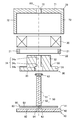
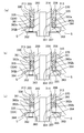
- FIG. 2A is a perspective view of the torque generator according to the first embodiment of the present invention as viewed from above, and (b) is a perspective view of the torque generator of (a) as viewed from below.
- FIG. 2A is a cross-sectional view showing a schematic configuration of the torque generator according to the first embodiment
- (b) is a functional block diagram showing a control system of the torque generator according to the first embodiment. It is an exploded sectional view of the torque generator shown in FIG. 2A. It is explanatory drawing which conceptually shows the magnetic field generated by the exciting coil in the torque generator shown in FIG. It is a partially enlarged view of FIG. 2 (a). It is sectional drawing which partially enlarged the schematic structure of the torque generator which concerns on the modification.
- FIG. (A) is a cross-sectional view showing a schematic configuration of a torque generator according to a third embodiment
- (b) is a partially enlarged view including a shaft 210a in (a)
- (c) is a shaft 210b in (a).
- It is sectional drawing along the rotation axis which shows the structure of the torque generator which concerns on 4th Embodiment.
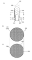
- (A) is a cross-sectional view along the rotation axis showing the configuration of the shaft
- (b) is a cross-sectional view taken along the line CC'of (a)
- (c) is a cross-sectional view taken along the line DD'of (a).
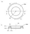
- (A) and (b) are views showing the structure of a V ring as an adjustment sealing member
- (a) is a plan view
- (b) is a sectional view taken along the line BB'of (a).
- .. (A), (b), and (c) are sectional views showing an enlarged view of a shaft, a guide portion, a ventilation portion, an accommodation space, two V-rings, and an adjustment space.
- (A) is a partially enlarged view of FIG. 15 (c)
- (b) is a cross-sectional view showing a state after air has flowed out from the adjustment space to the outside.
- FIG. 1A is a perspective view of the torque generator 10 according to the first embodiment as viewed from above
- FIG. 1B is a perspective view of the torque generator 10 as viewed from below
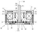
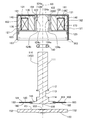
- FIG. 2A is a cross-sectional view showing a schematic configuration of the torque generator 10
- FIG. 2B is a functional block diagram showing a control system of the torque generator 10.
- FIG. 2A is a cross-sectional view taken along the line AA'of FIG. 1A.
- FIG. 3 is an exploded cross-sectional view of the torque generator 10 shown in FIG. 2 (a).
- FIG. 4 is an explanatory diagram conceptually showing the magnetic field generated by the exciting coil 20 in the torque generator 10 shown in FIG. 3 with arrows.
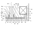
- FIG. 5 is a partially enlarged view of FIG. 2 (a).
- the vertical direction is defined along the rotation axis AX, but the direction in actual use is not limited.
- the direction along the rotation axis AX is referred to as an axial direction or a vertical direction, and the direction orthogonal to the rotation axis AX from the rotation axis AX is referred to as a radial direction.
- a state in which the lower side is viewed from the upper side along the rotation axis AX may be referred to as a plan view.
- the torque generator 10 includes a holding unit 11 and an operating unit 12.
- the operation unit 12 includes a shaft 50 and a magnetic disc 80, and is supported by a holding unit 11 so as to be rotatable in both directions around the rotation shaft AX of the shaft 50.
- the operating portion 12 is supported by the holding portion 11 in a rotatable state via the first bearing portion 34c and the second bearing portion 43 (see FIG. 5).
- the holding portion 11 includes a first yoke 30 including a first bearing portion 34c, a second yoke 40 including a second bearing portion 43, a third yoke 70, an annular member 21, and an exciting coil 20 as a magnetic field generating portion. ..
- the first yoke 30, the second yoke 40, the third yoke 70, and the annular member 21 constitute an external member.
- the shaft 50 is made of a non-magnetic material and includes a columnar base portion 51 having a constant diameter and a large diameter portion 52 provided at the lower end portion of the base portion 51 in the axial direction so as to have a diameter larger than that of the base portion 51. ..
- a magnetic disk 80 as a rotor is fixed to the bottom surface of the shaft 50 (the bottom surface of the large diameter portion 52).
- the magnetic disk 80 is arranged so that its central axis coincides with the rotation axis AX, and its upper surface 81 and lower surface 82 are perpendicular to the rotation axis AX.
- the magnetic disk 80 is a rotating plate that can rotate around the rotating shaft AX together with the shaft 50.
- a protrusion 84 projecting downward is provided at the center of the lower surface 82 of the magnetic disk 80.
- An external member is arranged on the outside of the magnetic disk 80.
- the outside of the magnetic disk 80 includes the upper side of the upper surface 81 in the vertical direction, the lower side of the lower surface 82, and the outer side of the outer peripheral edge 83 in the radial direction.
- the external member includes a first yoke 30, a second yoke 40, a third yoke 70, and an annular member 21, the first yoke 30 is arranged so as to cover the upper side of the magnetic disk 80, and the second yoke 40 is The third yoke 70 is arranged below the magnetic disk 80 so as to cover the upper side of the first yoke 30 and the radial outside of the magnetic disk 80.
- the first yoke 30, the second yoke 40, and the third yoke 70 are made of, for example, iron or steel and have a magnetic material.
- the first yoke 30 includes an annular portion 31 and a cylindrical portion 32 integrally provided so as to extend upward from the upper surface of the annular portion 31 concentrically with the annular portion 31.
- the annular portion 31 and the cylindrical portion 32 have a circular shape centered on the rotation axis AX in a plan view, and the outer diameter thereof of the cylindrical portion 32 is smaller than that of the annular portion 31. Due to the difference in outer diameter between the annular portion 31 and the cylindrical portion 32, the step portion 33 is formed on the outer side of the outer peripheral surface of the cylindrical portion 32.
- the first yoke 30 has a central hole 34 having a circular shape in a plan view around the rotation axis AX into which the shaft 50 can be inserted.
- the central hole portion 34 includes a first hole portion 34a and a second hole portion 34b having different inner diameters from each other along the direction of the rotation axis AX via the first bearing portion 34c.
- the first bearing portion 34c is provided at substantially the same position as the step portion 33 in the axial direction.
- the first hole portion 34a has an inner diameter substantially the same as the diameter of the base portion 51 of the shaft 50.
- the second hole portion 34b has an inner diameter larger than that of the large diameter portion 52 so as to form a storage space 61 (FIGS. 2A and 5) with the large diameter portion 52 of the shaft 50. It is a recess of an external member that is recessed radially outward from the first hole 34a.
- the shaft 50 When the shaft 50 is inserted into the central hole portion 34, the stepped portion between the base portion 51 and the large diameter portion 52 abuts on the first bearing portion 34c, so that the shaft 50 is supported from the outside in the radial direction by the first bearing portion 34c. And it can rotate relative to the first yoke 30.
- the lower surface of the first yoke 30 is formed as a first facing surface 35 as a first facing portion facing the upper surface 81 of the magnetic disk 80.
- the first facing surface 35 is formed so as to extend in the radial direction from the position of the second hole portion 34b of the central hole portion 34 to the position corresponding to the outer peripheral edge 83 of the magnetic disk 80.
- the second yoke 40 has a substantially disk shape and is arranged below the lower surface 82 of the magnetic disk 80.
- the upper surface of the second yoke 40 is formed as a second facing surface 41 as a second facing portion facing the lower surface 82 of the magnetic disk 80. Therefore, the first facing surface 35 as the first facing portion faces one surface (upper surface 81) of the magnetic disk 80, and the second facing surface 41 as the second facing portion faces the other surface (lower surface 82). To do.
- a second bearing portion 43 that receives the protrusion 84 of the magnetic disk 80 is provided at the center of the second yoke 40 in the radial direction.
- the second bearing portion 43 is a recess recessed downward from the second facing surface 41 corresponding to the shape of the protrusion 84, or a hole portion that penetrates the second yoke 40 up and down. It is preferable to have.
- the shaft 50 and the magnetic disk 80 are supported in the axial direction by the protrusion 84 of the magnetic disk 80 being supported by the second bearing 43.
- the third yoke 70 includes an upper wall portion 71 that covers the first yoke 30 and is in contact with the upper surface of the first yoke 30, and a side wall portion 72 that extends downward from the outer circumference of the upper wall portion 71.
- the plan-view shape of the upper wall portion 71 may be, for example, a circle in addition to the rectangle as shown in FIGS. 1A and 1B.
- the third yoke 70 has a substantially cylindrical through hole 73 in the region including the rotation axis AX (FIG. 2A).
- the through hole 73 penetrates the third yoke 70 in the vertical direction. As shown in FIG. 2A, the space in the through hole 73 communicates vertically with the space surrounded by the central hole portion 34 of the first yoke 30, and the shaft 50 can be inserted.
- a radial outer edge portion 42 of the second yoke 40 is connected to the inner surface of the side wall portion 72 of the third yoke 70.
- annular member 21 (external member)> In the radial direction, an annular member 21 made of a non-magnetic member and forming an annular shape is arranged between the first yoke 30 and the side wall portion 72 of the third yoke 70.
- the annular member 21 has a circular shape having substantially the same outer diameter as the exciting coil 20 arranged on the stepped portion 33 in a plan view.
- the annular member 21 is made of a non-magnetic material such as a thermosetting material, and is between the first yoke 30 and the third yoke 70 in the radial direction and between the exciting coil 20 and the second yoke 40 in the axial direction. Is fixed to.
- the lower surface 22 of the annular member 21 is arranged so as to form the same height as the first facing surface 35 of the first yoke 30 in the axial direction.
- the upper surface 81 of the magnetic disk 80 is separated from the first facing surface 35 of the first yoke 30 and the lower surface 22 of the annular member 21, while the outer peripheral edge 83 is the third yoke. It is separated from the side wall portion 72 of 70. Further, the lower surface 82 of the magnetic disk 80 is also arranged so as to be separated from the second facing surface 41 of the second yoke 40, except for the second bearing portion 43.
- a continuous gap S is formed between them.
- a magnetic viscous fluid 90 as a magnetically responsive material is arranged in this gap S.
- the gap S may be filled with only the ferrofluid 90, but air may be contained as long as the resistance to the shaft 50 can be secured.
- the shaft 50 is supported from the outside in the radial direction by the first bearing portion 34c of the central hole portion 34, and the magnetic disc 80 fixed to the shaft 50 is rotated by the second bearing portion 43 of the second yoke 40. It is supported in the axial direction of the shaft AX.
- the shaft 50 and the magnetic disc 80 can stably rotate relative to the first yoke 30 and the second yoke 40 as external members about the rotation axis AX.
- An annular exciting coil 20 wound around the rotation axis AX is arranged between the first yoke 30 and the third yoke 70 on the stepped portion 33 of the first yoke 30 in the radial direction. ing.
- the exciting coil 20 is arranged in the radial direction in a range corresponding to the outer portion of the magnetic disk 80 including the outer peripheral edge 83 of the magnetic disk 80 and the annular member 21. Further, the exciting coil 20 faces the magnetic disk 80 in the axial direction via the first yoke 30 and the annular member 21.
- the exciting coil 20 generates a magnetic field as a magnetic field generating unit by energizing from the control unit 25 (FIG. 2B).
- the control unit 25 controls the magnitude of the current applied to the exciting coil 20, thereby controlling the magnitude of the magnetic field generated by the exciting coil 20.
- the control unit 25 includes, for example, an energizing unit that energizes the coil, a central processing unit, and a storage device, and is supplied with electric power from a power source and executes a program stored in the storage device in the central processing unit. By performing control.
- FIG. 2A and FIGS. 3 to 5 the wiring between the control unit 25 and the exciting coil 20 is omitted.
- the exciting coil 20 is surrounded by a first yoke 30 and a third yoke 70 from inside and outside in the radial direction, and is surrounded by a second yoke 40 at the bottom and a third yoke 70 at the top. Therefore, the magnetic field generated by the exciting coil 20 is guided through the path formed by the first yoke 30, the second yoke 40, and the third yoke 70, and a magnetic circuit is formed.
- the first yoke 30 and the side wall portion 72 of the third yoke 70 are magnetically separated below the exciting coil 20. Therefore, the magnetic field lines do not pass in the radial direction between them, and the magnetic field lines flow in the vertical direction in the first yoke 30, and the magnetic force lines efficiently cross the magnetic disk 80 in the vertical direction.
- the direction of energization of the exciting coil 20 is reversed, a magnetic field line opposite to the magnetic field line shown in FIG. 4 is generated.
- the magnetic field lines of the magnetic field shown in FIG. 4 pass through the magnetic viscous fluid 90 in the gap S, the magnetic flux in the vertical direction crosses the magnetic disk 80, and the magnetic flux lines in the magnetic viscous fluid 90 along the radial direction. No magnetic flux is generated, or even if it is generated, its magnetic flux density is small.
- the magnetic viscous fluid 90 is a substance whose viscosity changes when a magnetic field is applied, and is, for example, a fluid in which particles (magnetic particles) made of a magnetic material are dispersed in a non-magnetic liquid (solvent). ..
- the magnetic particles contained in the ferrofluid 90 for example, carbon-containing iron-based particles and ferrite particles are preferable.
- the diameter of the magnetic particles is preferably 0.5 ⁇ m or more, more preferably 1 ⁇ m or more.
- the ferrofluid 90 preferably contains a coupling material that prevents the precipitation of magnetic particles.
- the ferrofluid 90 when a current is applied to the exciting coil 20 to generate a magnetic field, the ferrofluid 90 is given a magnetic field along the vertical direction. Due to this magnetic field, the magnetic particles dispersed in the magnetic viscous fluid 90 gather along the magnetic field lines, and the magnetic particles arranged in the vertical direction are magnetically connected to each other to form clusters. In this state, when a force for rotating the shaft 50 is applied in the direction centered on the rotation shaft AX, a shearing force acts on the connected magnetic particles, and a resistance force (torque) is generated by these magnetic particles. Therefore, the operator can feel the resistance as compared with the state where the magnetic field is not generated.
- a storage space 61 is formed in a hollow ring along the outer circumference of the shaft 50. It is provided in. In other words, the accommodation space 61 is formed between the outer peripheral surface 52a of the large diameter portion 52 of the shaft 50 and the recess provided in the first yoke 30 which is an external member.
- the O-ring 62 is a ring member made of an elastic material, and is an inner surface of the accommodation space 61, that is, an inner surface of the second hole portion 34b of the first yoke 30, and an outer circumference of the large diameter portion 52 of the shaft 50. It is in close contact with the surface 52a in a movable state while sliding up and down along the axial direction of the rotating shaft AX.
- the accommodation space 61 is connected to the gap S via the connecting portion 64 as a route.
- the ferrofluid 90 put into the gap S flows into the accommodation space 61 as well as the gap S. Since the O-ring 62 is in close contact with the inner surface in the accommodation space 61, the inflowing ferrofluid 90 stays at the position where the O-ring 62 is provided in the accommodation space 61 and does not flow above this position. ..
- the space below the position where the O-ring 62 is provided in the accommodation space 61 is the adjustment space 63.
- the accommodation space 61 including the adjustment space 63 is provided at a position between the first bearing portion 34c and the first facing surface 35 as the first facing portion in the axial direction. Further, the adjustment space 63 included in the accommodation space 61 is surrounded by the outer peripheral surface 52a of the large diameter portion 52 of the shaft 50, the recess provided in the first yoke 30 which is an external member, and the O-ring 62. It is formed.
- the accommodation space 61, the O-ring 62 as the adjustment sealing member, and the adjustment space 63 form an adjustment portion along the outer circumference of the shaft 50.
- the adjusting portion is formed between the shaft 50 and the external member in the radial direction.
- the O-ring 62 can move up and down in the accommodation space 61 while maintaining the liquidtightness of the adjustment space 63.
- the volume of the adjustment space 63 can be changed according to the volume change of the ferrofluid 90.
- the accommodation space 61 is provided so as to extend along the rotation axis AX, no new member is added, so that no major change in the manufacturing process is required, and the volume of the ferrofluid 90 is not required.
- the volume of the adjustment space 63 in which the ferrofluid 90 is enclosed can be scaled in a wide range according to the expansion and contraction of the magnetic viscous fluid 90. Therefore, even if the volume of the magnetically responsive material changes due to temperature change, aging, or the like, a stable and desired resistance force (torque) can be applied to the rotor.
- the adjusting sealing member is not limited to the O-ring 62 (O-ring), and for example, an X-ring can be used.
- the O-ring 62 easily moves downward when the pressure of the ferrofluid 90 decreases, so that the position of the O-ring 62 with respect to the volume change of the ferrofluid 90 Changes are smooth and quick.
- FIG. 6 is a partially enlarged cross-sectional view of the schematic configuration of the torque generator according to the modified example, and is a view at a position corresponding to FIG.
- FIG. 7 is a cross-sectional view showing a schematic configuration of the torque generator 100 according to the second embodiment.
- the torque generator 100 has an outer shape similar to that of the torque generator 10 of the first embodiment, and FIG. 7 is a cross-sectional view at a position corresponding to FIG.
- FIG. 8 is an exploded cross-sectional view of the torque generator 100 shown in FIG. 7.
- FIG. 9 is an explanatory diagram conceptually showing the magnetic field lines of the magnetic field generated by the exciting coil 170 in the torque generator 100 shown in FIG. 7 with arrows.
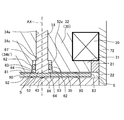
- FIG. 10 is a partially enlarged view of FIG. 7. In the following description, detailed description of the same configuration, action, and effect as in the first embodiment will be omitted.
- the torque generator 100 includes a holding unit 101 and an operating unit 102.
- the operation unit 102 includes a shaft 110 and a magnetic disk 180, and is supported by a holding unit 101 so as to be rotatable in both directions about the rotation shaft AX.
- the operating portion 102 is supported by the holding portion 101 in a rotatable state via the first bearing portion 124c and the second bearing portion 153 (see FIG. 10).
- the holding portion 101 includes a first sealing member 120 including a first bearing portion 124c, an inner yoke 130 (first yoke), an outer yoke 140, a second sealing member 150 including a second bearing portion 153, a housing 160, and a housing 160.
- the exciting coil 170 is provided as a magnetic field generating unit.
- the first sealing member 120, the inner yoke 130, the outer yoke 140, the second sealing member 150, and the housing 160 constitute an outer member.
- the shaft 110 is made of a non-magnetic material and includes a base portion 111, a flange portion 112, a concave portion 113, a large diameter portion 114, and a disk portion 115, which are continuously formed from the upper side to the lower side (FIG. 8).
- the base portion 111 has a columnar shape having a constant diameter, and the flange portion 112 is formed so as to spread outward from the lower end of the base portion 111 in a flange shape.
- the recess 113 is provided so as to be recessed inward in the radial direction from the lower surface of the flange portion 112, and is a small diameter portion having a diameter smaller than that of the base portion 111.
- the large diameter portion 114 is formed from the lower end of the recess 113 and has a columnar shape having the same diameter as the flange portion 112.
- the disc portion 115 extends outward from the lower end of the large diameter portion 114 and has a disc shape having a diameter larger than that of the large diameter portion 114. Further, a protruding portion 116 projecting downward is provided at the center of the lower surface of the disc portion 115.
- a magnetic disk 180 as a rotor is fixed to the outer edge of the disk portion 115 of the shaft 110.
- the magnetic disk 180 has an annular shape, and its central axis is arranged so as to coincide with the rotation axis AX.
- the upper surface 181 and the lower surface 182 of the magnetic disk 180 are perpendicular to the rotation axis AX.
- the magnetic disc 180 can rotate around the rotation shaft AX together with the shaft 110.
- An external member is arranged on the outside of the magnetic disk 180.
- the outside of the magnetic disk 180 includes an upper side of the upper surface 181 in the vertical direction, a lower side of the lower surface 182, and an outer side of the outer peripheral edge 183 in the radial direction.
- the external member includes a first sealing member 120, an inner yoke 130, an outer yoke 140, a second sealing member 150, and a housing 160.
- the first sealing member 120 is arranged so as to surround the upper side and the radial outer side of the magnetic disk 180, and the inner yoke 130 and the outer yoke 140 are arranged so as to cover the upper side of the first sealing member 120 and the magnetic disk 180.
- the second sealing member 150 is arranged below the magnetic disk 180.
- the housing 160 is arranged so as to surround the first sealing member 120, the inner yoke 130, the outer yoke 140, and the outer side of the second sealing member 150, which surround the magnetic disk 180.
- the first sealing member 120 is made of a non-magnetic material
- the inner yoke 130, the outer yoke 140, the second sealing member 150, and the housing 160 are made of, for example, iron or steel and have a magnetic material. ..
- the first sealing member 120 includes a disk portion 121, a cylindrical portion 122, and an annular portion 123.
- the cylindrical portion 122 is integrally provided so as to extend upward from the upper surface of the thin plate-shaped disc portion 121 concentrically with the disc portion 121.
- the annular portion 123 is provided so as to extend downward from the outer edge of the disc portion 121.
- the disk portion 121 and the cylindrical portion 122 have a circular shape centered on the rotation axis AX in a plan view, and the outer diameter thereof of the cylindrical portion 122 is smaller than that of the disk portion 121.
- the first sealing member 120 has a central hole portion 124 having a circular shape in a plan view around the rotation axis AX and into which a shaft 110 can be inserted.
- the central hole portion 124 includes a first hole portion 124a and a second hole portion 124b having different inner diameters along the direction of the rotation axis AX via the first bearing portion 124c.
- the first hole portion 124a has substantially the same inner diameter as the diameter of the base portion 111 of the shaft 110
- the second hole portion 124b has substantially the same inner diameter as the flange portion 112 and the large diameter portion 114 of the shaft 110.
- the accommodation space 191 is formed between the second hole portion 124b and the recess 113 of the shaft 110.
- the shaft 110 When the shaft 110 is inserted into the central hole portion 124, the stepped portion between the base portion 111 and the flange portion 112 abuts on the first bearing portion 124c, so that the shaft 110 is supported from the outside in the radial direction by the first bearing portion 124c. Moreover, it can rotate relative to the first sealing member 120.
- a gap P1 extending in the axial direction is provided between the cylindrical portion 122 of the first sealing member 120 and the large diameter portion 114 of the shaft 110, and the gap P1 is continuous with the gap P1.
- a gap P2 extending in the radial direction is provided between the disk portion 121 of the sealing member 120 and the disk portion 115 of the shaft 110.
- the disk portion 121 of the first sealing member 120 faces the upper surface 181 of the magnetic disk 180 as the first facing portion, and the lower surface of the disk portion 121 becomes the first facing surface 125 facing the magnetic disk 180. ing.
- the annular portion 123 is arranged so as to cover the radial outside of the magnetic disk 180, and the side wall portion 162 of the housing 160 is arranged outside the annular portion 123. Therefore, the magnetic disk 180 and the housing 160 are magnetically separated.
- the inner yoke 130 as the first yoke is made of a magnetic material and is arranged above the disk portion 121 of the first sealing member 120 in the axial direction and outside the cylindrical portion 122 in the radial direction. There is.
- the upper portion of the inner yoke 130 is a disk portion 131 extending in the radial direction above the exciting coil 170. With this configuration, the internal yoke 130 is arranged so as to cover the inside and the upper side of the exciting coil 170.
- the outer yoke 140 is an annular member arranged outside the inner yoke 130 with the exciting coil 170 interposed therebetween in the radial direction, and is connected to the radial outer end surface of the disk portion 131 of the inner yoke 130.
- the inner inner yoke 130 and the outer outer yoke 140 in the radial direction of the exciting coil 170 are magnetically connected via the disk portion 131.
- the second sealing member 150 has a substantially disk shape, and is arranged below the disk portion 115 of the shaft 110 and the magnetic disk 180 fixed to the disk portion 115.
- the upper surface of the second sealing member 150 is the second facing surface 151 as the second facing portion, and faces the lower surface 182 of the magnetic disk 180.
- a second bearing portion 153 that receives the protrusion 116 of the shaft 110 is provided at the center in the radial direction of the second sealing member 150.
- the second bearing portion 153 has a concave shape that is recessed downward from the second facing surface 151, corresponding to the shape of the protrusion 116.
- the shaft 110 and the magnetic disc 180 are supported in the axial direction by the protrusion 116 being supported by the second bearing 153.
- the housing 160 is made of a magnetic material and includes an upper wall portion 161 and a side wall portion 162 extending downward from the outer periphery of the upper wall portion 161.
- the inner surface (lower surface) of the upper wall portion 161 is fixed in contact with the upper surfaces of the inner yoke 130 and the outer yoke 140, and covers them.
- the inner surface of the side wall portion 162 is fixed in contact with the outer yoke 140, the outer side surface of the annular portion 123 of the first sealing member 120, and the outer peripheral surface 152 of the second sealing member 150, respectively.
- a tip locking portion 163 is provided at the lower end of the side wall portion 162.
- the plan view shape of the upper wall portion 161 may be, for example, a circle in addition to the rectangle as shown in FIGS. 1 (a) and 1 (b).
- the housing 160 has a substantially cylindrical through hole 164 in the region including the rotation shaft AX (FIGS. 7 and 8).
- the through hole 164 penetrates the housing 160 in the vertical direction.
- the first sealing member 120 is inserted into the through hole 164.
- the housing 160 is assembled to the first sealing member 120, the inner yoke 130, the outer yoke 140, and the exciting coil 170, which are fixed to each other, from the upper side in the axial direction.
- the side wall portion 162 and the tip locking portion 163 of the housing 160 are in a state of extending along the axial direction (solid line in FIG. 8).
- a shaft 110 to which the O-ring 192 and the magnetic disk 180 are mounted in advance is inserted into the first sealing member 120, and then the second sealing member 150 is inserted into the housing 160 so as to be located below the shaft 110.
- the shaft 110 and the second sealing member 150 are assembled in the housing 160 by bending the tip locking portion 163 inward in the radial direction (the state of the broken line in FIG. 8) (state in FIG. 7).
- the magnetic disk 180 is sandwiched from above and below by the inner yoke 130, the outer yoke 140, and the second sealing member 150, and in the radial direction, the annular portion 123 made of a non-magnetic material is formed. Through, it is surrounded by a housing 160.
- the upper surface 181 of the magnetic disk 180 is separated from the first facing surface 125 (disk portion 121) of the first sealing member 120, while the outer peripheral edge 183 is first sealed. It is separated from the annular portion 123 of the member 120. Further, the lower surface 182 is also arranged so as to be separated from the second facing surface 151 of the second sealing member 150.
- the magnetic disk 180, the first facing surface 125 (disk portion 121) of the first sealing member 120, the annular portion 123, the second sealing member 150, and the magnetic disk 180 surrounding the magnetic disk 180 are fixed.
- a continuous gap S is formed between the shaft 110 and the large diameter portion 114.
- a magnetically viscous fluid 190 as a magnetically responsive material is arranged in this gap S (FIG. 10).
- the shaft 110 is supported from the outside in the radial direction by the first bearing portion 124c of the first sealing member 120, and the magnetic disc 180 fixed to the shaft 110 is the second bearing of the second sealing member 150. It is supported by the portion 153 in the axial direction of the rotating shaft AX.
- the shaft 110 and the magnetic disk 180 have the rotating shaft AX with respect to the first sealing member 120, the inner yoke 130, the outer yoke 140, the second sealing member 150, and the housing 160 as external members. It is stable as a center and can rotate relative to each other.
- the shaft 110 to which the O-ring 192 and the magnetic disk 180 are mounted in advance is inserted into the first sealing member 120, and the magnetic viscous fluid 190 is sealed in the gap S.
- the second sealing member 150 is joined to the annular portion 123 of the first sealing member 120 so as to be integrated with the housing 160 in which the inner yoke 130, the outer yoke 140, and the exciting coil 170 are arranged. It may be a procedure.
- An annular exciting coil 170 wound around the rotation axis AX is arranged between the inner yoke 130 and the outer yoke 140 on the disk portion 121 of the first sealing member 120 in the radial direction. Has been done.
- the exciting coil 170 is arranged in a range corresponding to the magnetic disk 180 in the radial direction. Further, the exciting coil 170 faces the magnetic disk 180 in the axial direction via the disk portion 121 of the first sealing member 120.
- the exciting coil 170 generates a magnetic field as a magnetic field generating unit by energizing from a control unit similar to the control unit 25 of the first embodiment.
- the exciting coil 170 is surrounded from inside and outside in the radial direction by the inner yoke 130 and the outer yoke 140, and is surrounded from above and below by the disk portion 131 of the inner yoke 130 and the second sealing member 150. Further, it is surrounded by the housing 160 from above and below and from the outside in the radial direction. Therefore, the magnetic field generated by the exciting coil 170 is guided through the path (magnetic circuit) formed by the inner yoke 130, the outer yoke 140, the second sealing member 150, and the housing 160.
- magnetic force lines are generated in the direction opposite to the magnetic field lines in the second sealing member 150 and in the radial direction, and further, the inner yoke At 130, magnetic lines of force are generated in the direction opposite to the lines of magnetic force in the side wall portion 162 of the housing 160 and the outer yoke 140 in the vertical direction. As a result, the magnetic field lines pass up and down in the magnetic disk 180.
- the magnetic disk 180 and the side wall portion 162 are magnetically separated by arranging the annular portion 123 of the first sealing member 120 between the outer peripheral edge 183 of the magnetic disk 180 and the side wall portion 162 of the housing 160. Therefore, the magnetic field lines do not pass in the radial direction between them, and the magnetic field lines flow in the vertical direction in the internal yoke 130, and the magnetic field lines efficiently cross the magnetic disk 180 in the vertical direction.
- the direction of energization of the exciting coil 170 is reversed, a magnetic field line opposite to the magnetic field line shown in FIG. 9 is generated.
- the magnetic field lines of the magnetic field shown in FIG. 9 pass through the magnetic viscous fluid 190 in the gap S, the magnetic flux in the vertical direction crosses the magnetic disk 180, and the magnetic flux lines in the magnetic viscous fluid 190 along the radial direction. No magnetic flux is generated, or even if it is generated, its magnetic flux density is small.
- the magnetic viscous fluid 190 is the same as that of the first embodiment.
- a storage space 191 is provided in a hollow annular shape between the second hole portion 124b of the first sealing member 120, which is an external member, and the recess 113 (small diameter portion) of the shaft 110. ..
- the accommodation space 191 is connected to the gap S via the gaps P1 and P2.
- An O-ring 192 (O-ring) as an adjustment sealing member is arranged in the accommodation space 191.
- the O-ring 192 is made of an elastic material with respect to the inner surface of the accommodation space 191, that is, the inner surface of the second hole portion 124b of the first sealing member 120, and the outer peripheral surface 113a of the recess 113 of the shaft 110.
- the rotating shaft AX is in close contact with each other so as to be slidable up and down along the axial direction.
- the ferrofluid 190 put into the gap S flows into the accommodation space 191 not only through the gap S but also through the gaps P1 and P2 as a path.
- the inflowing ferrofluid 190 stays at the position where the O-ring 192 is provided in the accommodation space 191 and is above this position. Does not flow in.
- the space below the position where the O-ring 192 is provided in the accommodation space 191 is the adjustment space 193.
- the accommodation space 191 including the adjustment space 193 is provided at a position between the first bearing portion 124c and the first facing surface 125 in the axial direction.
- the accommodation space 191 and the O-ring 192 as the adjustment sealing member, and the adjustment space 193 form an adjustment portion along the outer circumference of the shaft 110.
- the adjusting portion is formed between the shaft 110 and the external member in the radial direction.
- the ferrofluid 190 is provided in the gap S, the adjustment space 193 in the accommodation space 191 and the gaps P1 and P2 as a path connecting the gap S and the adjustment space 193. It is enclosed.
- the O-ring 192 can move up and down in the accommodation space 191 while maintaining the liquidtightness of the adjustment space 193.
- the volume of the adjustment space 193 can be changed according to the volume change of the ferrofluid 190.
- FIG. 11 is a cross-sectional view showing a schematic configuration of the torque generator 200 according to the third embodiment, (b) is a partially enlarged view of (a) including a shaft 210a, and (c) is (a). It is a partially enlarged view including the shaft 210b.
- a magnetic disk is used as the rotor, and in this magnetic disk, the magnetic field lines of the magnetic field generated by the exciting coil cross in the direction along the rotation axis AX, but other than this.
- the torque generator 200 of the third embodiment can be configured.
- two shafts 210a and 210b arranged vertically are used, and a rotor provided with an internal yoke 220 and an exciting coil 250 is fixed between these shafts. ..
- the external member arranged on the outside of the rotor includes an external yoke 230 and a pair of fixing plates 241 and 242.
- the two shafts 210a and 210b are made of a non-magnetic material and are integrated with each other via an internal yoke 220 and an exciting coil 250 arranged between them in the axial direction of the rotating shaft AX.
- the shafts 210a and 210b can rotate around the rotation shaft AX together with the internal yoke 220 and the exciting coil 250. Therefore, the internal yoke 220 and the exciting coil 250 rotate around the rotation shaft AX as a rotor.
- the shaft 210a arranged on the upper side in the axial direction includes a shaft portion 211a extending along the axial direction and a disc portion 212a extending in the radial direction from the lower end of the shaft portion 211a.
- the shaft 210b arranged on the lower side in the axial direction includes a shaft portion 211b extending along the axial direction and a disc portion 212b extending in the radial direction from the upper end of the shaft portion 211b.
- the inner yoke 220 is made of a magnetic material and is fixed to both ends of a columnar core portion 221 extending in a direction orthogonal to the axial direction and both ends of the core portion 221 and facing each other with the rotation axis AX in between. , 222b and the like.
- the disc portion 212a of the upper shaft 210a is fixed to the upper surface of the two opposing portions 222a and 222b
- the disc portion 212b of the lower shaft 210b is fixed to the lower surface of the two opposing portions 222a and 222b.
- the radial outer surfaces of the two opposing portions 222a and 222b are formed as outer peripheral surfaces 223a and 223b that form a part of one circle in a plan view, respectively.
- the exciting coil 250 as the magnetic field generating portion is wound around the central axis of the columnar core portion 221 (the axis orthogonal to the rotation axis AX).
- An outer yoke 230 made of a magnetic material is arranged outside the inner yoke 220 as a rotor in the radial direction.
- the outer yoke 230 has a hollow cylindrical shape centered on the rotation axis AX, and its inner peripheral surface 231 faces the outer peripheral surfaces 223a and 223b of the two opposing portions 222a and 222b, respectively, via a gap S. are doing.
- a magnetic viscous fluid 290 as a magnetically responsive material is sealed in the gap S.
- Fixing plates 241 and 242 made of non-magnetic material are fixed to the upper part and the lower part of the outer yoke 230, respectively.
- the fixing plates 241 and 242 are disks arranged around the rotation axis AX, and holes 241a and 242a penetrating in the axial direction (thickness direction) are formed at the centers thereof, respectively.
- a magnetic field having a magnetic field line indicated by an arrow in FIG. 11 is generated.
- the magnetic lines of force reach the second facing portion 222b from the first facing portion 222a through the core portion 221 and flow from the second facing portion 222b to the outer yoke 230 facing the outer peripheral surface 223b. Further, a magnetic field line toward the first facing portion 222a is generated from the outer yoke 230 facing the outer peripheral surface 223a of the first facing portion 222a. As a result, the magnetic field lines pass in the radial direction in the gap S.
- the shaft portion 211a of the shaft 210a is inserted into the hole portion 241a of the upper fixing plate 241, and the shaft portion 211b of the shaft 210b is inserted into the hole portion 242a of the lower fixing plate 242.
- a storage space 261a is formed between the inner peripheral surface of the hole 241a and the outer peripheral surface 213a (FIG. 11 (b)) of the shaft portion 211a, and the inner peripheral surface of the hole 242a and the outer peripheral surface 213b of the shaft portion 211b (
- a storage space 261b is formed between the space and the space (C).
- the same O-ring 262a as in the first embodiment and the second embodiment is arranged as an adjustment sealing member.
- the O-ring 262a is in close contact with the inner peripheral surface of the hole 241a and the outer peripheral surface 213a of the shaft portion 211a in a state of being slidable up and down along the axial direction.
- the same O-ring 262b as in the first embodiment and the second embodiment is arranged as an adjustment sealing member.
- the O-ring 262b is in close contact with the inner peripheral surface of the hole 242a and the outer peripheral surface 213b of the shaft portion 211b in a state of being slidable up and down along the axial direction.
- a gap P21 is provided between the fixed plate 241 and the disk portion 212a facing each other.
- a gap P22 is provided between the fixing plates 242 facing each other and the disk portion 212b.
- the ferrofluid 290 in the gap S is arranged in a space connected to the adjustment spaces 263a and 263b in the accommodation spaces 261a and 261b up to the O-rings 262a and 262b through the gaps P21 and P22.
- the upper accommodation space 261a, the O-ring 262a, and the adjustment space 263a, and the lower accommodation space 261b, the O-ring 262b, and the adjustment space 263b form an adjustment portion along the outer periphery of the shafts 210a and 210b.
- the adjusting portion is formed between the shafts 210a and 210b and the external member in the radial direction.
- the accommodation spaces 261a and 261b are configured to have recesses in one of the shafts 210a and 210b and the fixing plates 241 and 242 as in the first embodiment and the second embodiment, the O-rings 262a and 262b This is preferable because the range of movement can be reliably regulated.
- the O-rings 262a and 262b maintain the liquidtightness of the adjustment spaces 263a and 263b in the accommodation spaces 261a and 261b, respectively. While doing so, you can move up and down. As a result, the volume of the adjustment space 263a and 263b can be changed according to the volume change of the ferrofluid 290.
- the other configurations, actions, and effects are the same as those in the first embodiment or the second embodiment.
- FIG. 12 is a cross-sectional view taken along the rotating shaft AX showing the configuration of the torque generator 300 according to the fourth embodiment
- FIG. 13A is a cross-sectional view taken along the rotating shaft AX showing the configuration of the shaft 350.
- (B) is a cross-sectional view taken along the line CC'of (a)
- (c) is a cross-sectional view taken along the line DD'of (a).
- 14 (a) and 14 (b) are views showing the configuration of the V ring 362b as the adjusting sealing member, (a) is a plan view, and (b) is a cross section taken along the line BB'of (a). It is a figure.
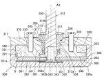
- FIG. 15 (a), (b), and (c) are enlarged cross-sectional views showing the shaft 350, the guide portion 313, the ventilation portion 314, the accommodation space 361, the two V-rings 362a and 362b, and the adjustment space 363.
- FIG. 15A is a partially enlarged view of FIG. 12, showing the initial state of the volume of the ferrofluid 390.
- FIG. 15 (b) shows a state in which the volume of the ferrofluid 390 increases and the two V-rings 362a and 362b are displaced upward until they abut on the lower surface of the guide portion 313, and
- FIG. 15 (c) is magnetic with respect to (b).
- FIG. 16A is a partially enlarged view of FIG. 15 (c)
- FIG. 16 (b) is a cross-sectional view showing a state after air has flowed out from the adjustment space 363.
- the torque generator 300 includes a holding unit 311 and an operating unit 312.
- the operation unit 312 includes a shaft 350 and a magnetic disk 380, and is supported by a holding unit 311 so as to be rotatable in both directions around the rotation shaft AX of the shaft 350.
- the operating portion 312 is supported by the holding portion 311 in a rotatable state via the guide portion 313 and the bearing portion 343.
- the holding portion 311 includes a guide portion 313, a first yoke 330, a second yoke 340 including a bearing portion 343, a third yoke 370, an annular member 321 and an exciting coil 320 as a magnetic field generating portion.
- the guide portion 313, the first yoke 330, the second yoke 340, the third yoke 370, and the annular member 321 constitute an external member.
- the shaft 350 is made of a non-magnetic material and has a substantially columnar shape. As shown in FIG. 12 or FIG. 16A, the shaft 350 includes a range corresponding to the guide portion 313 in the axial direction among the portions inserted into the holding portion 311 and includes the bottom surface 313a of the guide portion 313. A notch 356 is formed up to a predetermined position P3 in the accommodation space 361 with the upper limit of the above. As shown in FIG. 13 (c), the cutout portion 356 is a cutout portion of the outer peripheral surface 355 and forms a plane along the axial direction.
- the shaft 350 has an outer peripheral surface 355 having a circular shape in a plan view at the lower base portion 351 of the predetermined position P3 (see FIGS. 13A, 13B, and 13C).
- a step portion 357 is formed as a displacement portion that displaces the outer diameter of the shaft 350 by providing the notch portion 356.
- a flange portion 352 protruding in the radial direction is provided below the base portion 351, and a protruding portion 353 protruding downward is provided in the radial center portion of the flange portion 352.
- a magnetic disk 380 as a rotor is fixed to the outer peripheral surface of the protrusion 353 at the bottom of the shaft 350.
- the magnetic disk 380 is arranged so that its central axis coincides with the rotation axis AX, and its upper surface 381 and lower surface 382 are perpendicular to the rotation axis AX.
- the magnetic disc 380 is a rotating plate that can rotate around the rotating shaft AX together with the shaft 350, and can be rotated by a bearing portion 343 provided in the center of the second yoke 340 located below the magnetic disc 380. It is supported.
- An external member is arranged on the outside of the magnetic disk 380.
- the outside of the magnetic disk 380 includes the upper side of the upper surface 381 and the lower side of the lower surface 382 in the vertical direction, and the outer side of the outer peripheral edge 383 in the radial direction.
- the external member includes a guide portion 313, a first yoke 330, a second yoke 340, a third yoke 370, and an annular member 321 (FIG. 12).
- the guide portion 313 is arranged so that its inner peripheral surface 313b faces the outer peripheral surface of the shaft 350, and the first yoke 330 and the third yoke 370 are arranged outside the guide portion 313.
- the first yoke 330 is arranged so as to cover the upper side of the magnetic disk 380
- the second yoke 340 is arranged so as to cover the lower side of the magnetic disk 380 and the radial outer side of the first yoke 330.
- the third yoke 370 is arranged so as to cover the upper side of the first yoke 330 and the second yoke 340.
- the guide portion 313 is made of a non-magnetic material, and the first yoke 330, the second yoke 340, and the third yoke 370 are made of, for example, iron or steel and have a magnetic material.
- the guide portion 313 is a tubular member having an inner peripheral surface 313b having an inner diameter corresponding to the outer peripheral surface 355 of the shaft 350.
- the inner peripheral surface 313b and the outer peripheral surface 355 of the shaft 350 are arranged so as to be in contact with each other, whereby the shaft 350 is rotatably supported by the guide portion 313 and rotates relative to the external member. It will be possible.
- a ventilation portion 314 is formed between the guide portion 313 and the shaft 350 as a gap extending along the axial direction.
- the upper side of the ventilation portion 314 is connected to the outside in the axial direction, and the lower side in the axial direction is connected to the accommodation space 361. Therefore, the accommodation space 361 is connected to the outside through the ventilation portion 314.
- the first yoke 330 includes an annular portion 331 and a cylindrical portion 332, and a stepped portion 333 is formed on the outer side of the outer peripheral surface of the cylindrical portion, similarly to the first yoke 30 of the first embodiment. Will be done.
- the first yoke 330 has a central hole portion 334 having a circular shape in a plan view around the rotation axis AX into which the guide portion 313 can be inserted.
- a guide portion 313 is inserted into the central hole portion 334 up to a substantially intermediate position in the axial direction, and a storage space 361 is formed between the central hole portion 334 and the shaft 350 below the bottom surface 313a of the guide portion 313. There is.
- the lower surface 330a of the first yoke 330 is a first facing portion facing the upper surface 381 of the magnetic disk 380 as in the first embodiment, and is a position corresponding to the outer peripheral edge 383 of the magnetic disk 380 in the radial direction. It is formed by spreading to.
- the second yoke 340 includes a bottom wall portion 341 having a substantially disk shape in a plan view, and a side wall portion 342 extending axially upward from the peripheral edge portion of the bottom wall portion 341.
- the bottom wall portion 341 is arranged below the lower surface 382 of the magnetic disk 380, and the side wall portion 342 is arranged so as to cover the first yoke 330, the annular member 321 and the exciting coil 320 from the radial outside.
- the upper surface of the bottom wall portion 341 faces the lower surface 382 of the magnetic disk 380 as the second facing portion.
- one surface (upper surface 381) of the magnetic disk 380 faces the lower surface 330a of the first yoke 330 as the first facing portion, and the other surface (lower surface 382) faces the bottom wall portion as the second facing portion.
- the upper surfaces of 341 face each other.
- a bearing portion 343 that supports the shaft 350 is provided at the center in the radial direction of the second yoke 340, and the magnetic disc 380 fixed to the shaft 350 is also rotatably supported.
- the third yoke 370 has a substantially disk shape, and is arranged so as to cover the first yoke 330 and the side wall portion 342 of the second yoke 340 from above.
- the third yoke 370 has a substantially cylindrical through hole 371 that penetrates vertically in the region including the rotation axis AX.
- the through hole 371 communicates with the central hole portion 334 of the first yoke 330 in the vertical direction.
- a guide portion 313 is inserted and fixed in the through hole 371, and a shaft 350 is further inserted inside the guide portion 313.
- annular member 321 (external member)> As shown in FIG. 12, in the radial direction, an annular member 321 made of a non-magnetic member and forming an annular shape is arranged between the first yoke 330 and the side wall portion 342 of the second yoke 340.
- the annular member 321 has a circular shape having substantially the same outer diameter as the exciting coil 320 arranged on the step portion 333 in a plan view.
- the annular member 321 is fixed between the first yoke 330 and the second yoke 340 in the radial direction by a thermosetting material or the like which is a non-magnetic material.
- a material having appropriate elasticity may be used as the annular member 321 and may be pressure-welded between the first yoke 330 and the second yoke 340.
- the upper surface 381 is separated from the lower surface 330a of the first yoke 330 and the lower surface 321a of the annular member 321 while the outer peripheral edge 383 is separated from the side wall portion 342 of the second yoke 340. .. Further, the lower surface 382 of the magnetic disk 380 is also arranged so as to be separated from the bottom wall portion 341 of the second yoke 340.
- a continuous gap S is formed between the magnetic disk 380, the lower surface 330a of the first yoke 330, the lower surface 321a of the annular member 321 and the second yoke 340 surrounding the magnetic disk 380.
- a magnetic viscous fluid 390 as a magnetically responsive material is arranged in this gap S.
- the gap S may be filled with only the ferrofluid 390, but air may be contained as long as the resistance to the shaft 350 can be secured.
- the shaft 350 is supported from the outside in the radial direction by the inner peripheral surface 313b of the guide portion 313, and is supported in the axial direction of the rotating shaft AX by the bearing portion 343 of the second yoke 340.
- the shaft 350 and the magnetic disk 380 are stably relative to the guide portion 313, the first yoke 330, the second yoke 340, and the third yoke 370 as external members about the rotation axis AX. It becomes rotatable.
- ⁇ Magnetic field generator> As shown in FIG. 12, it is wound around the rotation axis AX on the stepped portion 333 of the first yoke 330 and between the first yoke 330 and the side wall portion 342 of the second yoke 340 in the radial direction.
- An annular exciting coil 320 is arranged.
- the exciting coil 320 is arranged in the radial direction in a range corresponding to the outer portion of the magnetic disk 380 including the outer peripheral edge 383 of the magnetic disk 380 and the annular member 321. Further, the exciting coil 320 faces the magnetic disk 380 in the axial direction via the first yoke 330 and the annular member 321.
- the control and operation of the exciting coil 320 is the same as that of the exciting coil 20 of the first embodiment.
- the exciting coil 320 is surrounded from inside and outside in the radial direction by the side wall portions 342 of the first yoke 330 and the second yoke 340, and below, the annular portion 331 of the first yoke 330 and the bottom wall portion 341 of the second yoke 340. Above, it is surrounded by a third yoke 370. Therefore, the magnetic field generated by the exciting coil 320 is guided through the path formed by the first yoke 330, the second yoke 340, and the third yoke 370 to form a magnetic circuit.
- the magnetic field lines of the magnetic field generated by the exciting coil 320 pass through the magnetic viscous fluid 390 in the gap S, and the magnetic flux in the vertical direction crosses the magnetic disk 380.
- the magnetic viscous fluid 390 uses the same substance as the magnetic viscous fluid 90 of the first embodiment.
- the dispersed magnetic particles gather along the lines of magnetic force and line up along the vertical direction, as in the case of the magnetic viscous fluid 90 of the first embodiment.
- the magnetic particles are magnetically connected to each other to form a cluster and a force is applied to rotate the shaft 350 in the direction centered on the rotation axis AX, a shearing force acts on the connected magnetic particles, and these Resistance (torque) is generated by magnetic particles. Therefore, the operator can feel the resistance as compared with the state where the magnetic field is not generated.
- the magnetic field generated by the exciting coil 320 is not generated, the magnetic particles are dispersed in the solvent, and when the operator operates the shaft 350, the holding unit 311 does not receive a large resistance force and is placed on the operating unit 312. It rotates relative to the relative.
- the outer peripheral surface of the shaft 350 is between the first yoke 330 and the shaft 350 in the radial direction and between the guide portion 313 and the flange portion 352 of the shaft 350 in the axial direction.
- the accommodation space 361 is provided in a hollow annular shape along the above.
- the inner wall of the accommodation space 361 includes a step portion 357 of the shaft 350, and the position of the step portion 357 in the axial direction is a specification for ventilation from the accommodation space 361 and two V rings 362a and 362b to be accommodated. It is determined according to the elasticity and shape of the.
- V-rings 362a and 362b as adjusting sealing members are arranged in the accommodation space 361.
- the V-rings 362a and 362b are ring members made of an elastic material, and have the same shape although they have different orientations. Taking the V-ring 362b arranged on the lower side as an example, as shown in FIG. 14A, the V-ring 362b is an annular shape centered on the rotation axis AX, and the above-mentioned annulus in a plan view.
- the circumferential direction D1 is defined so as to follow the outer shape of.
- the V-ring 362b is orthogonal to the circumferential direction D1 and has a V-shaped cross section including the rotation axis AX.
- the V-shape of the V-ring 362b is from one base point position P11 (upper surface position in FIG. 14 (b)) in the direction along the rotation axis AX to the other end position P12 (lower surface position in FIG. 14 (b)).
- the two arm-shaped portions A11 and A12 have a shape in which they extend respectively.
- the two arm-shaped portions A11 and A12 have the start end portions As joined to each other, and the distance increases in the radial direction toward the end point position P12.
- the basic feature of this shape is the same for the V ring 362a arranged on the upper side.
- the two V-rings 362a and 362b are arranged so as to be vertically upside down and overlapped in a direction along the rotation axis AX so that the base point position P11 is proximal to each other. That is, the upper V-ring 362a is arranged in a V-shape with the upper side open in the direction along the rotation axis AX, and the lower V-ring 362b is arranged in an inverted V-shape with the lower side open.
- the starting ends As of the two V-rings 362a and 362b are arranged in contact with or close to each other in the direction along the rotation axis AX.
- the cross-sections of the two V-rings 362a and 362b orthogonal to the circumferential direction D1 and including the rotation axis AX form an X-shape.
- the two V-rings 362a and 362b are arranged so that their V-shapes open as they are separated from each other along the axial direction of the rotation axis AX.
- the two V-rings 362a and 362b can be elastically deformed along the axial direction of the rotation axis AX and along the radial direction depending on the shape and the physical properties of the constituent materials. For example, in the state shown in FIG. 15A, the lower 362b is in contact with both the inner peripheral surface 335 of the first yoke 330 and the outer peripheral surface 355 of the shaft 350 in the radial direction due to elastic deformation.
- the fact that the two V-rings 362a and 362b come into contact with the surrounding members means that they are in close contact with each other so as to be slidable and movable up and down while blocking the passage of gas and liquid.
- the accommodation space 361 is connected to the gap S via the connecting portion 364 as a route.
- the gap S is filled with the ferrofluid 390, and the connection portion 364 and the accommodation space 361 are filled with air.
- the ferrofluid 390 placed in the gap S can flow into the accommodation space 361 through the connecting portion 364 as well as the gap S.
- the space below the position where the lower V ring 362b is provided is the adjustment space 363.
- the pressure of air inside the connection portion 364 and the adjustment space 363 increases or decreases. Therefore, the two V-rings 362a and 362b are integrally moved up and down by the pressure change of the air inside the connecting portion 364 and the adjusting space 363, and the upper end position of the adjusting space 363 is moved up and down according to the up and down. From the initial state shown in FIG. 15 (a), when the pressure of air in the adjustment space 363 increases due to the volume increase of the ferrofluid 390, as shown in FIG. 15 (b), there are two due to the increased pressure of air.
- the V-rings 362a and 362b are pushed upward.
- the two V-rings 362a and 362b abut on the bottom surface 313a of the guide portion 313 and contract vertically as shown in FIGS. 15 (c) and 16 (a).
- the lower V-ring 362b is located above the predetermined position P3 corresponding to the step portion 357.
- the magnetic viscous fluid 390 is used so that the amount of air inside the connection portion 364 and the adjustment space 363 is optimized. The filling amount can be adjusted.
- the upper part of the accommodation space 361 is connected to the ventilation portion 314, and the accommodation space 361, the two V-rings 362a and 362b, the adjustment space 363, and the ventilation portion 314 provide an adjustment portion along the outer circumference of the shaft 350. It is composed.
- the accommodation space 361 is connected to the outside air through the ventilation portion 314, and the two V-rings 362a and 362b are more than the stepped portion 357 (predetermined position P3) of the shaft 350 as the volume of the ferrofluid 390 increases.
- air can flow in and out between the adjustment space 363 and the outside through the ventilation portion 314 (FIGS. 15 (c) and 16 (a)).
- the air in the adjustment space 363 is on the lower side.
- the V-ring 362b suppresses the outflow into the accommodation space 361 above the adjustment space 363.
- FIG. 16A in a state where the two V-rings 362a and 362b are located above the predetermined position P3 corresponding to the step portion 357 due to the increase in the volume of the ferrofluid 390, the lower part is displayed.
- a gap G is formed between the V ring 362b on the side and the stepped portion 357 of the shaft 350. Due to the shape of the notch 356 and the stepped portion 357, the elasticity of the two V-rings 362a and 362b, and the viscosity of the ferrofluid 390, the air from the adjustment space 363 in the gap G (FIG. 16A).
- the space between the stepped portion 357 and the lower V-ring 362b is defined so that the two-dot chain line) can flow out and the ferrofluid 390 does not flow out above P3. Thereby, the increased pressure in the adjustment space 363 can be reduced. Further, after the pressure is lowered, as shown in FIG. 16B, the two V-rings 362a and 362b recover from the contracted state, and the lower V-ring 362b is displaced below the step portion 357. Therefore, the outflow of air to the outside is stopped and the desired pressure can be maintained.
- the other configurations, actions, and effects are the same as those in the first embodiment.
- the shaft 350 is provided with the notch portion 356, but instead of this, the first yoke 330 may be provided with the notch portion recessed outward in the radial direction. Further, instead of these, a through hole connecting to the outside is provided in the shaft 350 or the first yoke 330, and the outlet of the through hole is provided at the predetermined position P3, so that the two V rings 362a and 362b are in the predetermined positions. When the position beyond P3 is reached, the air in the adjustment space 363 may be discharged. Further, similarly to the ventilation portion 314 in the fourth embodiment, in the configurations of the first embodiment, the second embodiment, the third embodiment, and the modified examples thereof, the ventilation portion is provided between the shaft and the external member. It is also possible. Although the present invention has been described with reference to the above-described embodiment, the present invention is not limited to the above-described embodiment, and can be improved or modified within the purpose of improvement or the idea of the present invention.
- the ferrofluid is sealed by following the expansion and contraction of the volume of the ferrofluid without increasing the number of parts and without significantly changing the manufacturing process. It is useful in that the volume of the created space can be enlarged or reduced.
Landscapes
- Engineering & Computer Science (AREA)
- General Engineering & Computer Science (AREA)
- Mechanical Engineering (AREA)
- Physics & Mathematics (AREA)
- Electromagnetism (AREA)
- Braking Arrangements (AREA)
- Fluid-Damping Devices (AREA)
- Dynamo-Electric Clutches, Dynamo-Electric Brakes (AREA)
- Power Steering Mechanism (AREA)
Abstract
本発明のトルク発生装置は、シャフトに接続され、シャフトの回転軸を中心に回転動作可能なロータと、ロータの外側に配置され、回転軸を中心にロータと相対回転可能に設けられた外部部材と、ロータと外部部材との間の隙間に配置された磁気応答性材料と、磁気応答性材料を通過する磁界を発生させる磁界発生部と、シャフトの外周に沿ってシャフトと外部部材との間に設けられた調整部とを備える。調整部は、調整封止部材を内部に備えた収容空間を有し、磁気応答性材料は、隙間、収容空間、及び、これらをつなぐ経路に封入され、かつ、収容空間においては調整封止部材が設けられた位置から経路に至る調整空間に封入されており、調整部は、磁気応答性材料の体積変化に応じて調整空間の容積が変化可能とされている。このため、磁気粘性流体の体積の膨張収縮に追従して、磁気粘性流体が封入された空間の容積を拡大縮小することができる。
Description
本発明は、磁気応答性材料を用いて回転抵抗を変化させることができるトルク発生装置に関する。
特許文献1に記載の磁気粘性流体装置においては、互いに相対回転可能に設けられた2つの部材の間に磁気粘性流体が介在し、この磁気粘性流体に磁場を付与するための磁場発生部が設けられ、さらに、磁気粘性流体が装置本体外へ漏出しないように、シャフトとケーシング部材との隙間をシールするシール材が設けられている。そして、磁気粘性流体の体積の膨張収縮に追従して、磁気粘性流体が封入された空間の容積を拡大縮小するように動作する可撓性部材が設けられている。
しかしながら、特許文献1に記載の磁気粘性流体装置では、磁気粘性流体が封入された空間の容積を拡大縮小するための可撓性部材を新たに設けなければならないため、部品点数が増加するとともに、製造工程を変更することが必要となっていた。
そこで本発明は、部品点数を増やすことなく、かつ、製造工程を大きく変更することなく、磁気粘性流体の体積の膨張収縮に追従して、磁気粘性流体が封入された空間の容積を拡大縮小することができるトルク発生装置を提供することを目的とする。
上記課題を解決するために、本発明のトルク発生装置は、シャフトに接続され、シャフトの回転軸を中心に回転動作可能なロータと、ロータの外側に配置され、回転軸を中心にロータと相対回転可能に設けられた外部部材と、ロータと外部部材との間の隙間に配置された磁気応答性材料と、磁気応答性材料を通過する磁界を発生させる磁界発生部と、シャフトの外周に沿ってシャフトと外部部材との間に設けられた調整部とを備え、調整部は、調整封止部材を内部に備えた収容空間を有し、磁気応答性材料は、隙間、収容空間、及び、これらをつなぐ経路に封入され、かつ、収容空間においては調整封止部材が設けられた位置から経路に至る調整空間に封入されており、調整部は、磁気応答性材料の体積変化に応じて調整空間の容積が変化可能とされていることを特徴としている。
これにより、可撓性部材などの新たな部材を追加することなく、かつ、製造工程の大きな変更なく、磁気応答性材料の体積の膨張収縮に応じて、磁気応答性材料が封入された空間の容積を拡大縮小することができるトルク発生装置を提供することができる。よって、温度変化、経時変化等によって磁気応答性材料の体積に変化が生じたとしても、ロータに対して安定した、所望の抵抗力(トルク)を与えることができる。
本発明のトルク発生装置において、調整部は、収容空間において調整封止部材が回転軸の軸方向に沿って移動可能であることが好ましい。
収容空間内で調整封止部材が移動することによって調整空間の容積が変化可能となり、磁気応答性材料の体積の膨張収縮に応じて、磁気応答性材料が封入された空間の容積を拡大縮小することができる。また、回転軸の軸方向に沿って設けることにより、トルク発生装置の構成を大きく変えることなく、収容空間を広くとることができる。
収容空間内で調整封止部材が移動することによって調整空間の容積が変化可能となり、磁気応答性材料の体積の膨張収縮に応じて、磁気応答性材料が封入された空間の容積を拡大縮小することができる。また、回転軸の軸方向に沿って設けることにより、トルク発生装置の構成を大きく変えることなく、収容空間を広くとることができる。
本発明のトルク発生装置において、調整空間は、外部部材に設けられた凹部とシャフトの外周面との間に形成されていることが好ましい。
また、調整空間は、シャフトに設けられた小径部と、外部部材との間に形成されていることが好ましい。
これにより、新たな部材の追加や製造工程の大きな変更を要することなく、磁気応答性材料の体積変化に応じて調整空間を変化させることができる。
また、調整空間は、シャフトに設けられた小径部と、外部部材との間に形成されていることが好ましい。
これにより、新たな部材の追加や製造工程の大きな変更を要することなく、磁気応答性材料の体積変化に応じて調整空間を変化させることができる。
本発明のトルク発生装置において、調整封止部材は弾性を有するリング部材であることが好ましい。
これにより、調整空間の液密性を確保しつつ、調整封止部材を調整空間内で移動させることができる。よって、磁気応答性材料が調整空間から流出することを防げるため、磁気応答性材料の体積変化に対して精度良く調整空間を変化させることができる。
これにより、調整空間の液密性を確保しつつ、調整封止部材を調整空間内で移動させることができる。よって、磁気応答性材料が調整空間から流出することを防げるため、磁気応答性材料の体積変化に対して精度良く調整空間を変化させることができる。
本発明のトルク発生装置において、ロータは回転軸に垂直な面を有する回転板であり、外部部材は、シャフトを相対回転可能に支持する第1軸受部と、回転板の一方の面と対向する第1対向部とを有し、調整空間は、回転軸の軸方向において、第1軸受部と第1対向部との間の位置に設けられていることが好ましい。
これにより、ロータに対して広い面積で磁気応答性材料を接触させることが可能となるため、シャフトに与える抵抗力(トルク)の制御幅を広くとることができる。
これにより、ロータに対して広い面積で磁気応答性材料を接触させることが可能となるため、シャフトに与える抵抗力(トルク)の制御幅を広くとることができる。
本発明のトルク発生装置において、磁界発生部は、通電により磁界を発生するコイルを備え、外部部材は、コイルが発生する磁界を誘導する第1ヨークと第2ヨークとを備えることが好ましい。
これにより、磁界発生部が発生した磁界の磁力線が流れる磁気回路を構成でき、磁気応答性材料に対して効率的に磁力線を効果的に与えることで、所望の抵抗力を発生させることができる。
これにより、磁界発生部が発生した磁界の磁力線が流れる磁気回路を構成でき、磁気応答性材料に対して効率的に磁力線を効果的に与えることで、所望の抵抗力を発生させることができる。
本発明のトルク発生装置において、調整空間は、シャフトと第1ヨークとの間に設けられ、第1ヨークは、第1軸受部と第1対向部とを備え、第2ヨークは、回転板の他方の面と対向する第2対向部を有することが好ましい。
これにより、磁界発生部が発生した磁界を誘導するヨークをロータに接近して配置でき、効率良くロータに磁力線を通過させることができる。
これにより、磁界発生部が発生した磁界を誘導するヨークをロータに接近して配置でき、効率良くロータに磁力線を通過させることができる。
本発明のトルク発生装置において、第2ヨークは、シャフトを相対回転可能に支持する第2軸受部を備え、シャフトは、第1軸受部によって径方向外側から支持され、かつ、第2軸受部によって、回転軸の軸方向から支持されることが好ましい。
これにより、新たな部材を追加することなく、回転軸を安定して回転させる構成が実現できる。
これにより、新たな部材を追加することなく、回転軸を安定して回転させる構成が実現できる。
本発明のトルク発生装置において、第1対向部は薄板状をなしていることが好ましい。
これにより、装置全体の高さを小さく抑えることができる。
これにより、装置全体の高さを小さく抑えることができる。
本発明のトルク発生装置において、外部部材は、第1軸受部と第1対向部とを備える第1封止部材と、回転板及び隙間を挟んで、回転板の外周側で第1封止部材に接続される第2封止部材とを含むことが好ましい。
これにより、回転板との隙間に磁気応答性材料を封入するように第1封止部材と第2封止部材を互いに接合することができるため、磁気応答性材料を確実に保持しながら装置を解体することが可能となり、また、装置の仕様に応じて再利用することができる。
これにより、回転板との隙間に磁気応答性材料を封入するように第1封止部材と第2封止部材を互いに接合することができるため、磁気応答性材料を確実に保持しながら装置を解体することが可能となり、また、装置の仕様に応じて再利用することができる。
本発明のトルク発生装置において、第2封止部材は、シャフトを相対回転可能に支持する第2軸受部を備え、シャフトは、第1軸受部によって径方向外側から支持され、かつ、第2軸受部によって、回転軸の軸方向から支持されることが好ましい。
これにより、新たな部材を追加することなく、回転軸を安定して回転させる構成が実現できる。
これにより、新たな部材を追加することなく、回転軸を安定して回転させる構成が実現できる。
本発明のトルク発生装置において、磁界発生部は、通電により磁界を発生するコイルを備え、外部部材は、コイルが発生する磁界を誘導する第1ヨークをさらに備え、回転板と第2封止部材は磁性体からなることが好ましい。
これにより、磁界発生部が発生した磁界の磁力線が流れる磁気回路を構成でき、磁気応答性材料に対して効率的に磁力線を効果的に与えることで、所望の抵抗力を発生させることができる。
これにより、磁界発生部が発生した磁界の磁力線が流れる磁気回路を構成でき、磁気応答性材料に対して効率的に磁力線を効果的に与えることで、所望の抵抗力を発生させることができる。
本発明のトルク発生装置において、第1封止部材は非磁性体からなることが好ましい。
これにより、磁気回路への影響を抑えることができるため、効率的に抵抗力を発生させることができる。
これにより、磁気回路への影響を抑えることができるため、効率的に抵抗力を発生させることができる。
本発明のトルク発生装置において、シャフトは非磁性体からなることが好ましい。
これにより、磁力線がシャフトを通過せず、ロータのより外側に効率的に入るようになるため、抵抗力の制御幅を広くすることができる。
これにより、磁力線がシャフトを通過せず、ロータのより外側に効率的に入るようになるため、抵抗力の制御幅を広くすることができる。
本発明のトルク発生装置において、収容空間は、ロータに近づくほど平面視の面積が大きくなるように形成されていることが好ましい。
これにより、磁気応答性材料の圧力が低下したときに調整封止部材がロータ側へ移動しやすくなるため、磁気応答性材料の体積変化に対する調整封止部材の位置変化がスムーズかつ迅速に行われる。
これにより、磁気応答性材料の圧力が低下したときに調整封止部材がロータ側へ移動しやすくなるため、磁気応答性材料の体積変化に対する調整封止部材の位置変化がスムーズかつ迅速に行われる。
本発明のトルク発生装置において、調整封止部材は、少なくとも、回転軸の軸方向に沿って弾性変形可能な形状を有するリング部材であることが好ましい。
これにより、収容空間内で調整封止部材が弾性変形することによって調整空間の容積変化を大きくすることが可能となり、磁気応答性材料の体積の膨張収縮を補償することができる。
これにより、収容空間内で調整封止部材が弾性変形することによって調整空間の容積変化を大きくすることが可能となり、磁気応答性材料の体積の膨張収縮を補償することができる。
リング部材は、回転軸を中心とする周方向に直交する断面がV字状をなす2つのVリングからなり、上記V字状として、それぞれ、回転軸に沿った方向の一方の基端位置から他方の終端位置へ2本の腕状部が延び、かつ、2本の腕状部は、基端位置では始端部が互いに接合されており、終端位置へ向かうほど径方向に距離を広げており、さらに2つのVリングにおける始端部が回転軸に沿った方向において互いに接触又は近接するように配置されることが好ましい。
これにより、磁気応答性材料の体積の増減があったときは、調整封止部材が軸方向に移動しやすくなる。
これにより、磁気応答性材料の体積の増減があったときは、調整封止部材が軸方向に移動しやすくなる。
調整部は、収容空間に対して外部の空気の流出入を可能とする通気部を備えることが好ましい。
これにより、調整空間内の圧力が予め定めた値よりも高くなったときに限り、調整空間内の空気を外部へ逃がすことが可能となり、圧力を一定値以下に維持することができる。
これにより、調整空間内の圧力が予め定めた値よりも高くなったときに限り、調整空間内の空気を外部へ逃がすことが可能となり、圧力を一定値以下に維持することができる。
本発明によると、部品点数を増やすことなく、かつ、製造工程を大きく変更することなく、磁気粘性流体の体積の膨張収縮に追従して、磁気粘性流体が封入された空間の容積を拡大縮小可能なトルク発生装置を提供することができる。
以下、本発明の実施形態に係るトルク発生装置について図面を参照しつつ詳しく説明する。
<第1実施形態>
図1(a)は第1実施形態に係るトルク発生装置10を上側から見た斜視図、(b)はトルク発生装置10を下側から見た斜視図である。図2(a)はトルク発生装置10の概略構成を示す断面図、(b)はトルク発生装置10の制御系統を示す機能ブロック図である。図2(a)は、図1(a)のA-A’線に沿った断面図である。図3は図2(a)に示すトルク発生装置10の分解断面図である。図4は、図3に示すトルク発生装置10において励磁コイル20が発生した磁界を矢印で概念的に示す説明図である。図5は、図2(a)の一部拡大図である。
<第1実施形態>
図1(a)は第1実施形態に係るトルク発生装置10を上側から見た斜視図、(b)はトルク発生装置10を下側から見た斜視図である。図2(a)はトルク発生装置10の概略構成を示す断面図、(b)はトルク発生装置10の制御系統を示す機能ブロック図である。図2(a)は、図1(a)のA-A’線に沿った断面図である。図3は図2(a)に示すトルク発生装置10の分解断面図である。図4は、図3に示すトルク発生装置10において励磁コイル20が発生した磁界を矢印で概念的に示す説明図である。図5は、図2(a)の一部拡大図である。
各図において、説明の便宜上、回転軸AXに沿って上下方向を規定するが、実際の使用時における方向を制限するものではない。回転軸AXに沿った方向を軸方向又は上下方向とし、回転軸AXから、回転軸AXに直交する方向を径方向と称する。以下の説明において、回転軸AXに沿って、上側から下側を見た状態を平面視ということがある。
図2(a)に示すように、トルク発生装置10は、保持部11と操作部12とを備える。操作部12は、シャフト50と磁性ディスク80とを含み、シャフト50の回転軸AXを中心として両方向に回転動作可能に保持部11に支持されている。操作部12は、第1軸受部34cと第2軸受部43を介して、回転可能な状態で保持部11に支持されている(図5参照)。保持部11は、第1軸受部34cを含む第1ヨーク30、第2軸受部43を含む第2ヨーク40、第3ヨーク70、環状部材21、及び、磁界発生部としての励磁コイル20を備える。第1ヨーク30、第2ヨーク40、第3ヨーク70、及び、環状部材21は外部部材を構成する。
<シャフト50、磁性ディスク80>
シャフト50は非磁性体からなり、一定の直径の円柱状の基部51と、基部51の軸方向の下端部において、基部51よりも大きな直径を有するように設けられた大径部52とを備える。
シャフト50は非磁性体からなり、一定の直径の円柱状の基部51と、基部51の軸方向の下端部において、基部51よりも大きな直径を有するように設けられた大径部52とを備える。
シャフト50の底面(大径部52の底面)には、ロータとしての磁性ディスク80が固定されている。磁性ディスク80は、その中心軸が回転軸AXに一致するように配置されており、その上面81と下面82は回転軸AXに垂直となっている。磁性ディスク80は、シャフト50とともに回転軸AXを中心に回転動作可能とされた回転板である。
磁性ディスク80の下面82の中心には、下方に突出する突起部84が設けられている。
磁性ディスク80の下面82の中心には、下方に突出する突起部84が設けられている。
<外部部材>
磁性ディスク80の外側には外部部材が配置されている。磁性ディスク80の外側には、上下方向において上面81の上側、及び、下面82の下側、さらに、径方向において外周縁83の外側が含まれる。
磁性ディスク80の外側には外部部材が配置されている。磁性ディスク80の外側には、上下方向において上面81の上側、及び、下面82の下側、さらに、径方向において外周縁83の外側が含まれる。
外部部材は、第1ヨーク30、第2ヨーク40、第3ヨーク70、及び、環状部材21を備え、第1ヨーク30は、磁性ディスク80の上側を覆うように配置され、第2ヨーク40は磁性ディスク80の下側に配置され、さらに、第3ヨーク70は第1ヨーク30の上側と、磁性ディスク80の径方向外側を覆うように配置される。第1ヨーク30、第2ヨーク40、及び、第3ヨーク70は、例えば鉄や鋼であって磁性を有する材料で構成される。
<第1ヨーク30(外部部材)>
第1ヨーク30は、円環部31と、円環部31の上面から円環部31と同心状に上側へ延びるように一体に設けられた円筒部32とを備える。円環部31と円筒部32は、平面視において、回転軸AXを中心とする円形状をなしており、その外径は、円環部31よりも円筒部32の方が小さくされている。円環部31と円筒部32の外径の違いにより、円筒部32の外周面の外側に段差部33が形成される。
第1ヨーク30は、円環部31と、円環部31の上面から円環部31と同心状に上側へ延びるように一体に設けられた円筒部32とを備える。円環部31と円筒部32は、平面視において、回転軸AXを中心とする円形状をなしており、その外径は、円環部31よりも円筒部32の方が小さくされている。円環部31と円筒部32の外径の違いにより、円筒部32の外周面の外側に段差部33が形成される。
第1ヨーク30は、回転軸AXを中心とし、シャフト50を挿入可能な平面視円形状の中央孔部34を有する。中央孔部34は、回転軸AXの方向に沿って、第1軸受部34cを介して、内径が互いに異なる第1孔部34aと第2孔部34bとを備える。第1軸受部34cは軸方向において、段差部33と略同一位置に設けられている。
第1孔部34aは、シャフト50の基部51の直径と略同一の内径を有する。第2孔部34bは、シャフト50の大径部52との間に収容空間61(図2(a)、図5)を形成するように、大径部52よりも大きな内径を備えており、第1孔部34aよりも径方向外側へ凹んだ、外部部材の凹部をなしている。
中央孔部34内にシャフト50を挿通させると、基部51と大径部52との段差部分が第1軸受部34cに当接するため、第1軸受部34cによって、シャフト50が径方向外側から支持され、かつ、第1ヨーク30に対して相対回転可能となる。
第1ヨーク30の下面は、磁性ディスク80の上面81と対向する第1対向部としての第1対向面35として形成されている。この第1対向面35は、径方向において、中央孔部34の第2孔部34bの位置から磁性ディスク80の外周縁83に対応する位置まで広がって形成されている。
<第2ヨーク40(外部部材)>
第2ヨーク40は、略円板状をなし、磁性ディスク80の下面82の下方に配置される。第2ヨーク40の上面は、磁性ディスク80の下面82と対向する第2対向部としての第2対向面41として形成される。よって、磁性ディスク80の一方の面(上面81)に第1対向部としての第1対向面35が対向し、他方の面(下面82)に第2対向部としての第2対向面41が対向する。
第2ヨーク40は、略円板状をなし、磁性ディスク80の下面82の下方に配置される。第2ヨーク40の上面は、磁性ディスク80の下面82と対向する第2対向部としての第2対向面41として形成される。よって、磁性ディスク80の一方の面(上面81)に第1対向部としての第1対向面35が対向し、他方の面(下面82)に第2対向部としての第2対向面41が対向する。
第2ヨーク40の径方向の中央には、磁性ディスク80の突起部84を受容する第2軸受部43が設けられている。各図では簡略化しているが、第2軸受部43は突起部84の形状に対応して第2対向面41から下方に凹んだ凹部、又は、第2ヨーク40を上下に貫通する孔部であることが好ましい。磁性ディスク80の突起部84が第2軸受部43に支持されることによって、シャフト50と磁性ディスク80が軸方向において支持される。
<第3ヨーク70(外部部材)>
第3ヨーク70は、第1ヨーク30を覆い、かつ、第1ヨーク30の上面と接触する上壁部71と、上壁部71の外囲から下向きに延びる側壁部72とを備える。上壁部71の平面視形状は図1(a)、(b)に示すような矩形のほか、例えば円形とすることができる。
第3ヨーク70は、第1ヨーク30を覆い、かつ、第1ヨーク30の上面と接触する上壁部71と、上壁部71の外囲から下向きに延びる側壁部72とを備える。上壁部71の平面視形状は図1(a)、(b)に示すような矩形のほか、例えば円形とすることができる。
第3ヨーク70は、回転軸AXを含む領域に略円柱形の貫通孔73を有する(図2(a))。この貫通孔73は、第3ヨーク70を上下方向に貫通している。図2(a)に示すように、貫通孔73内の空間は、第1ヨーク30の中央孔部34に囲まれた空間と、上下方向に連通しており、シャフト50を挿入可能である。
さらに、第3ヨーク70の側壁部72の内面には、第2ヨーク40の径方向の外縁部42が接続される。これによって、磁性ディスク80が第1ヨーク30と第2ヨーク40によって挟まれるとともに、第3ヨーク70によって径方向外側が囲まれる。
<環状部材21(外部部材)>
径方向において、第1ヨーク30と第3ヨーク70の側壁部72との間には、非磁性部材からなり円環状をなす環状部材21が配置されている。この環状部材21は、平面視において、段差部33に配設された励磁コイル20と略同一の外径の円形状を有する。環状部材21は、非磁性材料である熱硬化性材料などにより、径方向においては第1ヨーク30と第3ヨーク70との間に、軸方向においては励磁コイル20と第2ヨーク40との間に固定される。図5に示すように、環状部材21は、その下面22が、軸方向において、第1ヨーク30の第1対向面35と同一高さをなすように配置されている。
径方向において、第1ヨーク30と第3ヨーク70の側壁部72との間には、非磁性部材からなり円環状をなす環状部材21が配置されている。この環状部材21は、平面視において、段差部33に配設された励磁コイル20と略同一の外径の円形状を有する。環状部材21は、非磁性材料である熱硬化性材料などにより、径方向においては第1ヨーク30と第3ヨーク70との間に、軸方向においては励磁コイル20と第2ヨーク40との間に固定される。図5に示すように、環状部材21は、その下面22が、軸方向において、第1ヨーク30の第1対向面35と同一高さをなすように配置されている。
図2(a)と図5に示すように、磁性ディスク80は、上面81が第1ヨーク30の第1対向面35及び環状部材21の下面22と離間する一方、外周縁83が第3ヨーク70の側壁部72と離間している。さらに、磁性ディスク80の下面82も、第2軸受部43を除いて、第2ヨーク40の第2対向面41と離間するように配置されている。
これにより、磁性ディスク80と、これを囲む、第1ヨーク30の第1対向面35、環状部材21、第3ヨーク70の側壁部72、及び、第2ヨーク40の第2対向面41との間に連続する隙間Sが形成される。この隙間Sには磁気応答性材料としての磁気粘性流体90が配置される。隙間S内は、磁気粘性流体90のみを充填してもよいが、シャフト50に対する抵抗力を確保できれば空気が入っていても良い。
以上のように、シャフト50が中央孔部34の第1軸受部34cによって径方向外側から支持され、かつ、シャフト50に固定された磁性ディスク80が第2ヨーク40の第2軸受部43によって回転軸AXの軸方向において支持されている。これにより、シャフト50と磁性ディスク80は、外部部材としての第1ヨーク30及び第2ヨーク40に対して、回転軸AXを中心として安定して相対回転可能となる。
<磁界発生部>
第1ヨーク30の段差部33上であって、径方向において第1ヨーク30と第3ヨーク70との間には、回転軸AXを中心として巻回された円環状の励磁コイル20が配置されている。励磁コイル20は、径方向において、磁性ディスク80の外周縁83を含む、磁性ディスク80の外側部分、及び、環状部材21に対応する範囲に配置されている。また、励磁コイル20は、軸方向において、第1ヨーク30及び環状部材21を介して磁性ディスク80と対向している。
第1ヨーク30の段差部33上であって、径方向において第1ヨーク30と第3ヨーク70との間には、回転軸AXを中心として巻回された円環状の励磁コイル20が配置されている。励磁コイル20は、径方向において、磁性ディスク80の外周縁83を含む、磁性ディスク80の外側部分、及び、環状部材21に対応する範囲に配置されている。また、励磁コイル20は、軸方向において、第1ヨーク30及び環状部材21を介して磁性ディスク80と対向している。
励磁コイル20は、磁界発生部として、制御部25(図2(b))からの通電により磁界を発生する。制御部25は、励磁コイル20に印加する電流の大きさを制御し、これによって励磁コイル20が発生する磁界の大きさを制御する。制御部25は、例えば、コイルに通電する通電部、中央演算処理装置、及び、記憶装置を含み、電源から電力が供給されるとともに、記憶装置に記憶されたプログラムを中央演算処理装置で実行することにより制御を実行する。
なお、図2(a)、及び、図3~図5においては制御部25と励磁コイル20との間の配線を省略している。
なお、図2(a)、及び、図3~図5においては制御部25と励磁コイル20との間の配線を省略している。
励磁コイル20は、第1ヨーク30と第3ヨーク70によって径方向の内外から囲まれるとともに、下方では第2ヨーク40により、上方では第3ヨーク70によって囲まれている。したがって、励磁コイル20が発生した磁界は、第1ヨーク30、第2ヨーク40、及び、第3ヨーク70によって形成される経路を通じて誘導され、磁気回路が形成される。
励磁コイル20に対して電流が印加されると、図4において矢印で示す磁力線を有する磁界が発生し、第2ヨーク40においては径方向に沿った磁力線が生じ、第3ヨーク70の側壁部72では上下方向に沿った方向の磁力線が生じる。さらに、第3ヨーク70の上壁部71では、第2ヨーク40における磁力線とは逆方向であって径方向に沿った方向の磁力線が生じ、さらに、第1ヨーク30では、側壁部72における磁力線とは逆方向で上下方向に沿った方向の磁力線が生じる。これによって、磁性ディスク80では磁力線が上下に通過する。
ここで、環状部材21を配置したことにより、励磁コイル20の下方において、第1ヨーク30と、第3ヨーク70の側壁部72とが磁気的に分離される。よって、これらの間で径方向に磁力線が通過することがなく、第1ヨーク30においては上下方向に沿って磁力線が流れ、この磁力線が磁性ディスク80を上下に効率よく横断する。
なお、励磁コイル20に対する通電方向を逆にすると、図4に示す磁力線とは逆向きの磁力線が生じる。
なお、励磁コイル20に対する通電方向を逆にすると、図4に示す磁力線とは逆向きの磁力線が生じる。
図4に示す磁界の磁力線は隙間S内の磁気粘性流体90を通過し、磁性ディスク80においては上下方向に沿った方向の磁束が横断し、磁気粘性流体90の内部では、径方向に沿った磁束は生じないか生じてもその磁束密度はわずかである。
ここで、磁気粘性流体90は、磁界が印加されると粘度が変化する物質であり、例えば、非磁性の液体(溶媒)中に磁性材料からなる粒子(磁性粒子)が分散された流体である。磁気粘性流体90に含まれる磁性粒子としては、例えば、カーボンを含有した鉄系の粒子やフェライト粒子が好ましい。磁性粒子の直径は、例えば0.5μm以上が好ましく、さらには1μm以上が好ましい。磁気粘性流体90は、磁性粒子が重力で沈殿しにくくなるように、溶媒と磁性粒子を選定することが望ましい。さらに、磁気粘性流体90は、磁性粒子の沈殿を防ぐカップリング材を含むことが望ましい。
磁気粘性流体90においては、励磁コイル20に電流を印加して磁界を発生させると、磁気粘性流体90には上下方向に沿った磁界が与えられる。この磁界により、磁気粘性流体90中で分散していた磁性粒子は磁力線に沿って集まり、上下方向に沿って並んだ磁性粒子が磁気的に互いに連結され、クラスタが形成される。この状態において、回転軸AXを中心とする方向にシャフト50を回転させようとする力を与えると、連結された磁性粒子にせん断力がはたらき、これらの磁性粒子による抵抗力(トルク)が生じる。このため、磁界を発生させていない状態と比べて操作者に抵抗力を感じさせることができる。
一方、励磁コイル20による磁界が生じていないときには、磁性粒子は溶媒内で分散されている。したがって、操作者がシャフト50を操作すると、保持部11は、大きな抵抗力を受けずに、操作部12に対して相対的に回転する。
<調整部>
図5に示すように、第1ヨーク30の中央孔部34の第2孔部34bと、シャフト50の大径部52との間には、シャフト50の外周に沿って収容空間61が中空環状に設けられている。別言すると、収容空間61は、シャフト50の大径部52の外周面52aと外部部材である第1ヨーク30に設けられた凹部との間に形成されている。
図5に示すように、第1ヨーク30の中央孔部34の第2孔部34bと、シャフト50の大径部52との間には、シャフト50の外周に沿って収容空間61が中空環状に設けられている。別言すると、収容空間61は、シャフト50の大径部52の外周面52aと外部部材である第1ヨーク30に設けられた凹部との間に形成されている。
収容空間61内には調整封止部材としてのオーリング62(Oリング)が配置されている。オーリング62は、弾性を有する材料で構成されたリング部材であり、収容空間61の内面、すなわち、第1ヨーク30の第2孔部34bの内面、及び、シャフト50の大径部52の外周面52aに対して、回転軸AXの軸方向に沿って上下に摺動しつつ移動可能な状態で密着している。
収容空間61は、経路としての接続部64を介して、隙間Sに連なっている。隙間S内に入れられた磁気粘性流体90は、隙間Sだけでなく、収容空間61内へ流入する。収容空間61内ではオーリング62が内面に密着しているため、流入した磁気粘性流体90は、収容空間61のうちオーリング62が設けられた位置でとどまり、この位置よりも上側には流入しない。
ここで、収容空間61のうちオーリング62が設けられた位置より下側の空間は調整空間63である。調整空間63を含む収容空間61は、軸方向において、第1軸受部34cと、第1対向部としての第1対向面35との間の位置に設けられている。また、収容空間61に含まれる調整空間63は、シャフト50の大径部52の外周面52aと、外部部材である第1ヨーク30に設けられた凹部と、オーリング62とで囲まれるように形成される。
収容空間61、調整封止部材としてのオーリング62、及び、調整空間63により調整部がシャフト50の外周に沿って構成される。調整部は、径方向において、シャフト50と外部部材との間に形成される。このような調整部を設けたことにより、磁気粘性流体90は、隙間Sと、収容空間61のうちの調整空間63、及び、隙間Sと調整空間63をつなぐ経路としての接続部64に封入される。
磁気粘性流体90の体積が変化すると、オーリング62は収容空間61内で、調整空間63の液密性を維持しつつ、上下に移動することができる。これにより、磁気粘性流体90の体積変化に応じて調整空間63の容積が変化可能となる。ここで、収容空間61を回転軸AXに沿って延びるように設けているため、新たな部材を追加することがないことから、製造工程の大きな変更を要することがなく、磁気粘性流体90の体積の膨張収縮に応じて、磁気粘性流体90が封入された調整空間63の容積を広い範囲で拡大縮小させることができる。よって、温度変化、経時変化等によって磁気応答性材料の体積に変化が生じたとしても、ロータに対して安定した、所望の抵抗力(トルク)を与えることができる。
また、調整封止部材としては、オーリング62(Oリング)に限定されず、例えばXリングを用いることもできる。また、上述の第2孔部34b及び収容空間61に代えて、図6に示すように、収容空間61’が、下側(磁性ディスク80(ロータ)側)に近づくほど平面視の面積が大きくなるように第2孔部34b’を形成すると、磁気粘性流体90の圧力が低下したときにオーリング62が下側へ移動しやすくなるため、磁気粘性流体90の体積変化に対するオーリング62の位置変化がスムーズかつ迅速に行われる。ここで、図6は、変形例に係るトルク発生装置の概略構成を一部拡大した断面図であって、図5に対応する位置における図である。
<第2実施形態>
図7は、第2実施形態に係るトルク発生装置100の概略構成を示す断面図である。このトルク発生装置100は第1実施形態のトルク発生装置10と同様の外形形状を備え、図7は図2に対応する位置における断面図である。図8は、図7に示すトルク発生装置100の分解断面図である。図9は、図7に示すトルク発生装置100において励磁コイル170が発生した磁界の磁力線を概念的に矢印で示す説明図である。図10は、図7の一部拡大図である。以下の説明において第1実施形態と同様の構成、作用、効果については詳細な説明を省略する。
図7は、第2実施形態に係るトルク発生装置100の概略構成を示す断面図である。このトルク発生装置100は第1実施形態のトルク発生装置10と同様の外形形状を備え、図7は図2に対応する位置における断面図である。図8は、図7に示すトルク発生装置100の分解断面図である。図9は、図7に示すトルク発生装置100において励磁コイル170が発生した磁界の磁力線を概念的に矢印で示す説明図である。図10は、図7の一部拡大図である。以下の説明において第1実施形態と同様の構成、作用、効果については詳細な説明を省略する。
図7に示すように、トルク発生装置100は、保持部101と操作部102とを備える。操作部102は、シャフト110と磁性ディスク180とを含み、回転軸AXを中心として両方向に回転動作可能に保持部101に支持されている。操作部102は、第1軸受部124cと第2軸受部153を介して、回転可能な状態で保持部101に支持されている(図10参照)。保持部101は、第1軸受部124cを含む第1封止部材120、内部ヨーク130(第1ヨーク)、外部ヨーク140、第2軸受部153を含む第2封止部材150、ハウジング160、及び、磁界発生部としての励磁コイル170を備える。第1封止部材120、内部ヨーク130、外部ヨーク140、第2封止部材150、及び、ハウジング160は外部部材を構成する。
<シャフト110、磁性ディスク180>
シャフト110は非磁性体からなり、上側から下側へ順に連続して形成された、基部111と、フランジ部112と、凹部113と、大径部114と、円板部115とを備える(図8参照)。基部111は一定の直径の円柱状をなしており、フランジ部112は、基部111の下端から外方へ鍔状に広がるように形成されている。凹部113は、フランジ部112の下面から径方向内側に凹むように設けられ、基部111よりも小さな直径を有する小径部とされている。大径部114は、凹部113の下端から形成され、フランジ部112と同一の直径の円柱状をなしている。円板部115は大径部114の下端から外方へ広がって、大径部114よりも大きな直径を有する円板状をなしている。さらに、円板部115の下面の中心には、下方に突出する突起部116が設けられている。
シャフト110は非磁性体からなり、上側から下側へ順に連続して形成された、基部111と、フランジ部112と、凹部113と、大径部114と、円板部115とを備える(図8参照)。基部111は一定の直径の円柱状をなしており、フランジ部112は、基部111の下端から外方へ鍔状に広がるように形成されている。凹部113は、フランジ部112の下面から径方向内側に凹むように設けられ、基部111よりも小さな直径を有する小径部とされている。大径部114は、凹部113の下端から形成され、フランジ部112と同一の直径の円柱状をなしている。円板部115は大径部114の下端から外方へ広がって、大径部114よりも大きな直径を有する円板状をなしている。さらに、円板部115の下面の中心には、下方に突出する突起部116が設けられている。
シャフト110の円板部115の外縁部には、ロータとしての磁性ディスク180が固定されている。磁性ディスク180は、円環状をなしており、その中心軸が回転軸AXに一致するように配置されている。磁性ディスク180の上面181と下面182は回転軸AXに垂直となっている。磁性ディスク180は、シャフト110とともに回転軸AXを中心に回転動作可能とされている。
<外部部材>
磁性ディスク180の外側には外部部材が配置されている。磁性ディスク180の外側には、上下方向において上面181の上側、及び、下面182の下側、さらに、径方向において外周縁183の外側が含まれる。
磁性ディスク180の外側には外部部材が配置されている。磁性ディスク180の外側には、上下方向において上面181の上側、及び、下面182の下側、さらに、径方向において外周縁183の外側が含まれる。
外部部材は、第1封止部材120、内部ヨーク130、外部ヨーク140、第2封止部材150、及び、ハウジング160を備える。第1封止部材120は、磁性ディスク180の上側及び径方向外側を囲んで配置され、内部ヨーク130と外部ヨーク140は、第1封止部材120及び磁性ディスク180の上側を覆うように配置される。第2封止部材150は磁性ディスク180の下側に配置される。ハウジング160は、磁性ディスク180を囲んだ、第1封止部材120、内部ヨーク130、外部ヨーク140、及び、第2封止部材150の外側を囲むように配置される。第1封止部材120は非磁性材料で構成され、内部ヨーク130、外部ヨーク140、第2封止部材150、及び、ハウジング160は、例えば鉄や鋼であって磁性を有する材料で構成される。
<第1封止部材120(外部部材)>
第1封止部材120は、円板部121、円筒部122、及び、環状部123を備える。円筒部122は、薄板状の円板部121の上面から円板部121と同心状に上側へ延びるように一体に設けられている。環状部123は、円板部121の外縁から下方に延びるように設けられている。円板部121と円筒部122は、平面視において、回転軸AXを中心とする円形状をなしており、その外径は、円板部121よりも円筒部122の方が小さくされている。
第1封止部材120は、円板部121、円筒部122、及び、環状部123を備える。円筒部122は、薄板状の円板部121の上面から円板部121と同心状に上側へ延びるように一体に設けられている。環状部123は、円板部121の外縁から下方に延びるように設けられている。円板部121と円筒部122は、平面視において、回転軸AXを中心とする円形状をなしており、その外径は、円板部121よりも円筒部122の方が小さくされている。
図7に示すように、第1封止部材120は、回転軸AXを中心とし、シャフト110を挿入可能な平面視円形状の中央孔部124を有する。図8に示すように、中央孔部124は、回転軸AXの方向に沿って、第1軸受部124cを介して、内径が互いに異なる第1孔部124aと第2孔部124bとを備える。
第1孔部124aは、シャフト110の基部111の直径と略同一の内径を有し、第2孔部124bは、シャフト110のフランジ部112及び大径部114と略同一の内径を有する。これにより、第2孔部124bと、シャフト110の凹部113との間に収容空間191が形成される。
中央孔部124内にシャフト110を挿通させると、基部111とフランジ部112との段差部分が第1軸受部124cに当接するため、第1軸受部124cによって、シャフト110が径方向外側から支持され、かつ、第1封止部材120に対して相対回転可能となる。
図10に示すように、第1封止部材120の円筒部122とシャフト110の大径部114との間には軸方向に延びる間隙P1が設けられ、この間隙P1に連続するように、第1封止部材120の円板部121とシャフト110の円板部115との間には径方向に延びる間隙P2が設けられている。
第1封止部材120の円板部121は、第1対向部として磁性ディスク180の上面181と対向しており、円板部121の下面は磁性ディスク180と対向する第1対向面125となっている。
環状部123は、磁性ディスク180の径方向外側を覆うように配置されており、環状部123の外側にハウジング160の側壁部162が配置されている。したがって、磁性ディスク180とハウジング160は磁気的には隔離される。
<内部ヨーク130(外部部材)>
第1ヨークとしての内部ヨーク130は、磁性材料で構成され、軸方向において第1封止部材120の円板部121よりも上側であって、径方向において円筒部122よりも外側に配置されている。内部ヨーク130の上部は、励磁コイル170の上方において径方向に広がる円板部131とされている。この構成により、内部ヨーク130は励磁コイル170の内側と上側を覆うように配置される。
第1ヨークとしての内部ヨーク130は、磁性材料で構成され、軸方向において第1封止部材120の円板部121よりも上側であって、径方向において円筒部122よりも外側に配置されている。内部ヨーク130の上部は、励磁コイル170の上方において径方向に広がる円板部131とされている。この構成により、内部ヨーク130は励磁コイル170の内側と上側を覆うように配置される。
<外部ヨーク140(外部部材)>
外部ヨーク140は、径方向において、励磁コイル170を挟んで内部ヨーク130の外側に配置された円環状部材であり、内部ヨーク130の円板部131の径方向外側の端面に接続されている。これにより、励磁コイル170の径方向の内側の内部ヨーク130と外側の外部ヨーク140が円板部131を介して磁気的に接続される。
外部ヨーク140は、径方向において、励磁コイル170を挟んで内部ヨーク130の外側に配置された円環状部材であり、内部ヨーク130の円板部131の径方向外側の端面に接続されている。これにより、励磁コイル170の径方向の内側の内部ヨーク130と外側の外部ヨーク140が円板部131を介して磁気的に接続される。
<第2封止部材150(外部部材)>
第2封止部材150は、略円板状をなし、シャフト110の円板部115及びこれに固定された磁性ディスク180の下方に配置されている。第2封止部材150の上面は、第2対向部としての第2対向面151であって、磁性ディスク180の下面182と対向する。
第2封止部材150は、略円板状をなし、シャフト110の円板部115及びこれに固定された磁性ディスク180の下方に配置されている。第2封止部材150の上面は、第2対向部としての第2対向面151であって、磁性ディスク180の下面182と対向する。
第2封止部材150の径方向の中央には、シャフト110の突起部116を受容する第2軸受部153が設けられている。第2軸受部153は、突起部116の形状に対応して第2対向面151から下方に凹んだ凹部形状を有している。突起部116が第2軸受部153に支持されることによって、シャフト110と磁性ディスク180が軸方向において支持される。
<ハウジング160(外部部材)>
ハウジング160は、磁性材料で構成され、上壁部161と、上壁部161の外囲から下向きに延びる側壁部162とを備える。上壁部161は、その内面(下面)が内部ヨーク130及び外部ヨーク140の上面と接触して固定され、かつ、これらを覆う。側壁部162は、その内面が、外部ヨーク140、第1封止部材120の環状部123の外側の側面、及び、第2封止部材150の外周面152にそれぞれ接触して固定されている。側壁部162の下端には先端係止部163が設けられている。上壁部161の平面視形状は図1(a)、(b)に示すような矩形のほか、例えば円形とすることができる。
ハウジング160は、磁性材料で構成され、上壁部161と、上壁部161の外囲から下向きに延びる側壁部162とを備える。上壁部161は、その内面(下面)が内部ヨーク130及び外部ヨーク140の上面と接触して固定され、かつ、これらを覆う。側壁部162は、その内面が、外部ヨーク140、第1封止部材120の環状部123の外側の側面、及び、第2封止部材150の外周面152にそれぞれ接触して固定されている。側壁部162の下端には先端係止部163が設けられている。上壁部161の平面視形状は図1(a)、(b)に示すような矩形のほか、例えば円形とすることができる。
ハウジング160は、回転軸AXを含む領域に略円柱形の貫通孔164を有する(図7、図8)。貫通孔164は、ハウジング160を上下方向に貫通している。この貫通孔164内には、第1封止部材120が挿通される。
図7と図8に示すように、ハウジング160は、互いに固定された、第1封止部材120、内部ヨーク130、外部ヨーク140、及び、励磁コイル170に対して、軸方向上側から組み付けられる。組み付けの際には、ハウジング160の側壁部162と先端係止部163は軸方向に沿って延びた状態となっている(図8の実線)。
さらに、第1封止部材120内に、予めオーリング192と磁性ディスク180を装着させたシャフト110を挿通させ、その後、シャフト110の下方に位置するようにハウジング160内に第2封止部材150を挿入する。この状態において、先端係止部163を径方向内側に屈曲(図8の破線の状態)させることにより、ハウジング160内にシャフト110と第2封止部材150が組み付けられる(図7の状態)。
このような組み付け工程により、磁性ディスク180は、内部ヨーク130及び外部ヨーク140と第2封止部材150とによって上下から挟まれるとともに、径方向においては、非磁性材料で構成される環状部123を介して、ハウジング160によって囲まれる。
図7と図10に示すように、磁性ディスク180は、上面181が、第1封止部材120の第1対向面125(円板部121)と離間する一方、外周縁183が第1封止部材120の環状部123と離間している。さらに、下面182も第2封止部材150の第2対向面151と離間するように配置されている。
これにより、磁性ディスク180と、これを囲む、第1封止部材120の第1対向面125(円板部121)、環状部123、第2封止部材150、及び、磁性ディスク180が固定されたシャフト110の大径部114との間に連続する隙間Sが形成される。この隙間Sには磁気応答性材料としての磁気粘性流体190が配置される(図10)。
以上のように、シャフト110が第1封止部材120の第1軸受部124cによって径方向外側から支持され、かつ、シャフト110に固定された磁性ディスク180が第2封止部材150の第2軸受部153によって回転軸AXの軸方向において支持されている。これにより、シャフト110と磁性ディスク180は、外部部材としての、第1封止部材120、内部ヨーク130、外部ヨーク140、第2封止部材150、及び、ハウジング160に対して、回転軸AXを中心として安定して相対回転可能となる。
なお、ハウジング160内に順に組み付けていく手順でなく、第1封止部材120内に、予めオーリング192と磁性ディスク180を装着させたシャフト110を挿通させ、隙間Sに磁気粘性流体190を封入するように第2封止部材150を第1封止部材120の環状部123に接合しておいてから、内部ヨーク130、外部ヨーク140、及び、励磁コイル170を配置したハウジング160と一体化する手順としてもよい。
なお、ハウジング160内に順に組み付けていく手順でなく、第1封止部材120内に、予めオーリング192と磁性ディスク180を装着させたシャフト110を挿通させ、隙間Sに磁気粘性流体190を封入するように第2封止部材150を第1封止部材120の環状部123に接合しておいてから、内部ヨーク130、外部ヨーク140、及び、励磁コイル170を配置したハウジング160と一体化する手順としてもよい。
<磁界発生部>
第1封止部材120の円板部121上であって、径方向において内部ヨーク130と外部ヨーク140との間には、回転軸AXを中心として巻回された円環状の励磁コイル170が配置されている。励磁コイル170は、径方向において、磁性ディスク180に対応する範囲に配置されている。また、励磁コイル170は、軸方向において、第1封止部材120の円板部121を介して磁性ディスク180と対向している。
第1封止部材120の円板部121上であって、径方向において内部ヨーク130と外部ヨーク140との間には、回転軸AXを中心として巻回された円環状の励磁コイル170が配置されている。励磁コイル170は、径方向において、磁性ディスク180に対応する範囲に配置されている。また、励磁コイル170は、軸方向において、第1封止部材120の円板部121を介して磁性ディスク180と対向している。
励磁コイル170は、磁界発生部として、第1実施形態の制御部25と同様の制御部からの通電により磁界を発生する。
励磁コイル170は、内部ヨーク130と外部ヨーク140によって径方向の内外から囲まれるとともに、内部ヨーク130の円板部131と第2封止部材150によって上下から囲まれている。さらに、ハウジング160によって、上下及び径方向外側から囲まれている。よって、励磁コイル170が発生した磁界は、内部ヨーク130、外部ヨーク140、第2封止部材150、及び、ハウジング160によって形成される経路(磁気回路)を通じて誘導される。
励磁コイル170に対して電流が印加されると、図9において矢印で示す磁力線を有する磁界が発生し、第2封止部材150においては径方向に沿った磁力線が生じ、ハウジング160の側壁部162及び外部ヨーク140では上下方向に沿った方向の磁力線が生じる。さらに、ハウジング160の上壁部161及び内部ヨーク130の円板部131では、第2封止部材150における磁力線とは逆方向であって径方向に沿った方向の磁力線が生じ、さらに、内部ヨーク130では、ハウジング160の側壁部162及び外部ヨーク140における磁力線とは逆方向で上下方向に沿った方向の磁力線が生じる。これによって、磁性ディスク180では磁力線が上下に通過する。
ここで、磁性ディスク180の外周縁183とハウジング160の側壁部162との間に第1封止部材120の環状部123を配置したことにより、磁性ディスク180と側壁部162とが磁気的に分離されるため、これらの間で径方向に磁力線が通過することがなく、内部ヨーク130においては上下方向に沿って磁力線が流れ、この磁力線が磁性ディスク180を上下に効率よく横断する。
なお、励磁コイル170に対する通電方向を逆にすると、図9に示す磁力線とは逆向きの磁力線が生じる。
なお、励磁コイル170に対する通電方向を逆にすると、図9に示す磁力線とは逆向きの磁力線が生じる。
図9に示す磁界の磁力線は隙間S内の磁気粘性流体190を通過し、磁性ディスク180においては上下方向に沿った方向の磁束が横断し、磁気粘性流体190の内部では、径方向に沿った磁束は生じないか生じてもその磁束密度はわずかである。
ここで、磁気粘性流体190は第1実施形態と同様のものを用いている。
ここで、磁気粘性流体190は第1実施形態と同様のものを用いている。
<調整部>
図10に示すように、外部部材である第1封止部材120の第2孔部124bと、シャフト110の凹部113(小径部)との間には収容空間191が中空環状に設けられている。この収容空間191は、上記間隙P1、P2を経路として、隙間Sに連なっている。
図10に示すように、外部部材である第1封止部材120の第2孔部124bと、シャフト110の凹部113(小径部)との間には収容空間191が中空環状に設けられている。この収容空間191は、上記間隙P1、P2を経路として、隙間Sに連なっている。
収容空間191内には調整封止部材としてのオーリング192(Oリング)が配置されている。オーリング192は、弾性を有する材料で構成され、収容空間191の内面、すなわち、第1封止部材120の第2孔部124bの内面、及び、シャフト110の凹部113の外周面113aに対して、回転軸AXの軸方向に沿って上下に摺動可能な状態で密着している。
隙間S内に入れられた磁気粘性流体190は、隙間Sだけでなく、経路としての間隙P1、P2を介して収容空間191内へ流入する。ここで、収容空間191内ではオーリング192が内面に密着しているため、流入した磁気粘性流体190は、収容空間191のうちオーリング192が設けられた位置でとどまり、この位置よりも上側には流入しない。
ここで、収容空間191のうちオーリング192が設けられた位置より下側の空間は調整空間193である。調整空間193を含む収容空間191は、軸方向において、第1軸受部124cと、第1対向面125との間の位置に設けられている。
収容空間191、調整封止部材としてのオーリング192、及び、調整空間193により調整部がシャフト110の外周に沿って構成される。調整部は、径方向において、シャフト110と外部部材との間に形成されている。
以上のような調整部を設けたことにより、磁気粘性流体190は、隙間Sと、収容空間191のうちの調整空間193と、隙間Sと調整空間193をつなぐ経路としての間隙P1、P2とに封入される。
磁気粘性流体190の体積が変化すると、オーリング192は収容空間191内で、調整空間193の液密性を維持しつつ、上下に移動することができる。これにより、磁気粘性流体190の体積変化に応じて調整空間193の容積が変化可能となる。
なお、その他の構成、作用、効果は第1実施形態と同様である。
なお、その他の構成、作用、効果は第1実施形態と同様である。
<第3実施形態>
図11(a)は、第3実施形態に係るトルク発生装置200の概略構成を示す断面図、(b)は(a)のうちシャフト210aを含む一部拡大図、(c)は(a)のうちシャフト210bを含む一部拡大図である。第1実施形態と第2実施形態においては、ロータとして磁性ディスクを用い、この磁性ディスクにおいては、励磁コイルが発生した磁界の磁力線が回転軸AXに沿った方向に横断していたが、これ以外の形態として第3実施形態のトルク発生装置200のような構成とすることもできる。
図11(a)は、第3実施形態に係るトルク発生装置200の概略構成を示す断面図、(b)は(a)のうちシャフト210aを含む一部拡大図、(c)は(a)のうちシャフト210bを含む一部拡大図である。第1実施形態と第2実施形態においては、ロータとして磁性ディスクを用い、この磁性ディスクにおいては、励磁コイルが発生した磁界の磁力線が回転軸AXに沿った方向に横断していたが、これ以外の形態として第3実施形態のトルク発生装置200のような構成とすることもできる。
第3実施形態に係るトルク発生装置200では、上下に分かれて配置された2つのシャフト210a、210bを用い、これらのシャフトの間に内部ヨーク220と励磁コイル250を備えたロータが固定されている。このロータの外側に配置される外部部材は、外部ヨーク230と一対の固定板241、242とを備える。
2つのシャフト210a、210bは、非磁性材料からなり、回転軸AXの軸方向において、その間に配置された、内部ヨーク220と励磁コイル250を介して互いに一体化されている。シャフト210a、210bは、内部ヨーク220及び励磁コイル250とともに回転軸AXを中心として回転可能とされている。よって、内部ヨーク220と励磁コイル250は、ロータとして、回転軸AXを中心に回転動作する。
軸方向上側に配置されるシャフト210aは、軸方向に沿って延びる軸部211aと、軸部211aの下端から径方向に広がる円板部212aを備える。同様に、軸方向下側に配置されるシャフト210bは、軸方向に沿って延びる軸部211bと、軸部211bの上端から径方向に広がる円板部212bを備える。
内部ヨーク220は、磁性材料で構成され、軸方向に直交する方向に延びる柱状のコア部221と、コア部221の両端にそれぞれ固定され、回転軸AXを挟んで互いに対向する2つの対向部222a、222bとを備える。
2つの対向部222a、222bの上面には、上側のシャフト210aの円板部212aが固定され、2つの対向部222a、222bの下面には、下側のシャフト210bの円板部212bが固定される。2つの対向部222a、222bの径方向の外面は、平面視において、1つの円の一部を構成する外周面223a、223bとしてそれぞれ形成されている。
磁界発生部としての励磁コイル250は、柱状のコア部221の中心軸(回転軸AXに直交する軸)を中心として巻回されている。
ロータとしての内部ヨーク220の径方向の外側には、磁性材料で構成される外部ヨーク230が配置されている。外部ヨーク230は、回転軸AXを中心とする中空の円筒形状を有し、その内周面231は、2つの対向部222a、222bそれぞれの外周面223a、223bに対して隙間Sを介して対向している。この隙間Sには、磁気応答性材料としての磁気粘性流体290が封入される。
外部ヨーク230の上部と下部には、非磁性材料からなる固定板241、242がそれぞれ固定されている。固定板241、242は、回転軸AXを中心として配置される円板であり、その中心には、軸方向(厚み方向)に貫通する孔部241a、242aがそれぞれ形成されている。
励磁コイル250に対して電流が印加されると、図11において矢印で示す磁力線を有する磁界が発生する。この磁力線は、第1対向部222aからコア部221を通って第2対向部222bへ至り、第2対向部222bから、この外周面223bに対向する外部ヨーク230へ流れる。また、第1対向部222aの外周面223aに対向する外部ヨーク230からは、第1対向部222aへ向かう磁力線が生じる。これによって、隙間Sにおいては磁力線が径方向に通過する。
上側の固定板241の孔部241aには、シャフト210aの軸部211aが挿通され、下側の固定板242の孔部242aには、シャフト210bの軸部211bが挿通される。孔部241aの内周面と軸部211aの外周面213a(図11(b))との間には収容空間261aが形成され、孔部242aの内周面と軸部211bの外周面213b(図11(c))との間には収容空間261bが形成されている。
上側の収容空間261a内には、調整封止部材として、第1実施形態と第2実施形態と同様のオーリング262aが配置されている。オーリング262aは、孔部241aの内周面と軸部211aの外周面213aに対して、軸方向に沿って上下に摺動可能な状態で密着している。また、下側の収容空間261b内にも、調整封止部材として、第1実施形態と第2実施形態と同様のオーリング262bが配置されている。オーリング262bは、孔部242aの内周面と軸部211bの外周面213bに対して、軸方向に沿って上下に摺動可能な状態で密着している。
互いに対向する、固定板241と円板部212aの間には間隙P21が設けられる。同様に、互いに対向する固定板242と円板部212bの間には間隙P22が設けられている。隙間S内の磁気粘性流体290は、これらの間隙P21、P22を経路として、収容空間261a、261b内のオーリング262a、262bまでの調整空間263a、263bまで連なる空間に配置される。
上側の収容空間261a、オーリング262a、及び、調整空間263a、並びに、下側の収容空間261b、オーリング262b、及び、調整空間263bにより、調整部がシャフト210a、210bの外周に沿って構成される。調整部は、径方向において、シャフト210a、210bと外部部材との間に形成されている。
ここで、収容空間261a、261bは、第1実施形態及び第2実施形態と同様に、シャフト210a、210b及び固定板241、242の一方に凹部を設けた構成にすると、オーリング262a、262bの移動範囲を確実に規制できるため好ましい。
以上のような調整部を設けたことにより、磁気粘性流体290の体積が変化すると、オーリング262a、262bは、それぞれ、収容空間261a、261b内で、調整空間263a、263bの液密性を維持しつつ、上下に移動することができる。これにより、磁気粘性流体290の体積変化に応じて調整空間263a、263bの容積が変化可能となる。
なお、その他の構成、作用、効果は第1実施形態又は第2実施形態と同様である。
なお、その他の構成、作用、効果は第1実施形態又は第2実施形態と同様である。
<第4実施形態>
図12は、第4実施形態に係るトルク発生装置300の構成を示す、回転軸AXに沿った断面図、図13(a)はシャフト350の構成を示す、回転軸AXに沿った断面図、(b)は(a)のC-C’線における断面図、(c)は(a)のD-D’における断面図である。図14(a)、(b)は、調整封止部材としてのVリング362bの構成を示す図であり、(a)は平面図、(b)は(a)のB-B’線における断面図である。図15(a)、(b)、(c)は、シャフト350、ガイド部313、通気部314、収容空間361、2つのVリング362a、362b、及び、調整空間363を拡大して示す断面図である。図15(a)は、図12の一部拡大図であって、磁気粘性流体390の体積が初期の状態を示している。図15(b)は磁気粘性流体390の体積が増加し、2つのVリング362a、362bがガイド部313の下面に当接するまで上側へ変位した状態、(c)は(b)に対して磁気粘性流体390の体積がさらに増加し、2つのVリング362a、362bが所定位置P3(図16(a))を超えた位置まで収縮した状態を示している。図16(a)は図15(c)の一部拡大図、(b)は調整空間363から外部へ空気が流出した後の状態を示す断面図である。
図12は、第4実施形態に係るトルク発生装置300の構成を示す、回転軸AXに沿った断面図、図13(a)はシャフト350の構成を示す、回転軸AXに沿った断面図、(b)は(a)のC-C’線における断面図、(c)は(a)のD-D’における断面図である。図14(a)、(b)は、調整封止部材としてのVリング362bの構成を示す図であり、(a)は平面図、(b)は(a)のB-B’線における断面図である。図15(a)、(b)、(c)は、シャフト350、ガイド部313、通気部314、収容空間361、2つのVリング362a、362b、及び、調整空間363を拡大して示す断面図である。図15(a)は、図12の一部拡大図であって、磁気粘性流体390の体積が初期の状態を示している。図15(b)は磁気粘性流体390の体積が増加し、2つのVリング362a、362bがガイド部313の下面に当接するまで上側へ変位した状態、(c)は(b)に対して磁気粘性流体390の体積がさらに増加し、2つのVリング362a、362bが所定位置P3(図16(a))を超えた位置まで収縮した状態を示している。図16(a)は図15(c)の一部拡大図、(b)は調整空間363から外部へ空気が流出した後の状態を示す断面図である。
図12に示すように、トルク発生装置300は、保持部311と操作部312とを備える。操作部312は、シャフト350と磁性ディスク380とを含み、シャフト350の回転軸AXを中心として両方向に回転動作可能に保持部311に支持されている。操作部312は、ガイド部313と軸受部343を介して、回転可能な状態で保持部311に支持されている。保持部311は、ガイド部313、第1ヨーク330、軸受部343を含む第2ヨーク340、第3ヨーク370、環状部材321、及び、磁界発生部としての励磁コイル320を備える。ガイド部313、第1ヨーク330、第2ヨーク340、第3ヨーク370、及び、環状部材321は外部部材を構成する。
<シャフト350、磁性ディスク380>
シャフト350は非磁性体からなり、略円柱状の形状を備える。図12又は図16(a)に示すように、シャフト350には、保持部311内に挿入される部分のうち、軸方向において、ガイド部313に対応する範囲を含み、ガイド部313の底面313aを上限とする収容空間361内の所定位置P3まで切り欠き部356が形成されている。切り欠き部356は、図13(c)に示すように、外周面355の一部を切り欠いたものであり、軸方向に沿った平面をなしている。シャフト350は、上記所定位置P3の下側の基部351では平面視円形状の外周面355を有している(図13(a)、(b)、(c)参照)。上記所定位置P3においては、切り欠き部356を設けたことによってシャフト350の外径を変位させる変位部としての段差部357が形成される。さらに、基部351の下方には径方向に突出したフランジ部352が設けられ、フランジ部352の径方向中央部には下方に突出する突起部353が設けられている。
シャフト350は非磁性体からなり、略円柱状の形状を備える。図12又は図16(a)に示すように、シャフト350には、保持部311内に挿入される部分のうち、軸方向において、ガイド部313に対応する範囲を含み、ガイド部313の底面313aを上限とする収容空間361内の所定位置P3まで切り欠き部356が形成されている。切り欠き部356は、図13(c)に示すように、外周面355の一部を切り欠いたものであり、軸方向に沿った平面をなしている。シャフト350は、上記所定位置P3の下側の基部351では平面視円形状の外周面355を有している(図13(a)、(b)、(c)参照)。上記所定位置P3においては、切り欠き部356を設けたことによってシャフト350の外径を変位させる変位部としての段差部357が形成される。さらに、基部351の下方には径方向に突出したフランジ部352が設けられ、フランジ部352の径方向中央部には下方に突出する突起部353が設けられている。
図12に示すように、シャフト350の底部の突起部353の外周面には、ロータとしての磁性ディスク380が固定されている。磁性ディスク380は、その中心軸が回転軸AXに一致するように配置されており、その上面381と下面382は回転軸AXに垂直となっている。磁性ディスク380は、シャフト350とともに回転軸AXを中心に回転動作可能とされた回転板であり、磁性ディスク380の下方に位置する第2ヨーク340の中心に設けられた軸受部343によって回転可能に支持されている。
<外部部材>
磁性ディスク380の外側には外部部材が配置されている。磁性ディスク380の外側には、上下方向において上面381の上側、及び、下面382の下側、さらに、径方向において外周縁383の外側が含まれる。
磁性ディスク380の外側には外部部材が配置されている。磁性ディスク380の外側には、上下方向において上面381の上側、及び、下面382の下側、さらに、径方向において外周縁383の外側が含まれる。
外部部材は、ガイド部313、第1ヨーク330、第2ヨーク340、第3ヨーク370、及び、環状部材321を備える(図12)。ガイド部313は、その内周面313bがシャフト350の外周面に対向するように配置され、第1ヨーク330と第3ヨーク370はガイド部313の外側に配置される。第1ヨーク330は、磁性ディスク380の上側を覆うように配置され、第2ヨーク340は、磁性ディスク380の下側と第1ヨーク330の径方向外側を覆うように配置される。第3ヨーク370は、第1ヨーク330と第2ヨーク340の上側を覆うように配置される。ガイド部313は非磁性体で構成され、第1ヨーク330、第2ヨーク340、及び、第3ヨーク370は、例えば鉄や鋼であって磁性を有する材料で構成される。
<ガイド部313(外部部材)>
図12に示すように、ガイド部313は、シャフト350の外周面355に対応する内径の内周面313bを有する筒状部材である。ガイド部313においては、内周面313bとシャフト350の外周面355とが互いに接触するように配置され、これによって、シャフト350はガイド部313によって回転可能に支持され、外部部材に対して相対回転可能となる。
図12に示すように、ガイド部313は、シャフト350の外周面355に対応する内径の内周面313bを有する筒状部材である。ガイド部313においては、内周面313bとシャフト350の外周面355とが互いに接触するように配置され、これによって、シャフト350はガイド部313によって回転可能に支持され、外部部材に対して相対回転可能となる。
ガイド部313において、シャフト350の切り欠き部356に対向する部分では、シャフト350との間に、軸方向に沿って延びる隙間としての通気部314が形成される。この通気部314は、軸方向の上側は外部に通じており、軸方向の下側は収容空間361に連なっている。したがって、収容空間361は、通気部314を介して外部に通じている。
<第1ヨーク330(外部部材)>
図12に示すように、第1ヨーク330は、第1実施形態の第1ヨーク30と同様に、円環部331と円筒部332を備え、円筒部の外周面の外側に段差部333が形成される。
図12に示すように、第1ヨーク330は、第1実施形態の第1ヨーク30と同様に、円環部331と円筒部332を備え、円筒部の外周面の外側に段差部333が形成される。
第1ヨーク330は、回転軸AXを中心とし、ガイド部313を挿入可能な平面視円形状の中央孔部334を有する。中央孔部334には、軸方向の略中間位置までの上側部分に、ガイド部313が挿入され、ガイド部313の底面313aより下側では、シャフト350との間に収容空間361が形成されている。
第1ヨーク330の下面330aは、第1実施形態と同様に、磁性ディスク380の上面381と対向する第1対向部となっており、径方向において、磁性ディスク380の外周縁383に対応する位置まで広がって形成されている。
<第2ヨーク340(外部部材)>
第2ヨーク340は、平面視で略円板状の底壁部341と、底壁部341の周縁部から軸方向上側へ延びた側壁部342とを備える。底壁部341は、磁性ディスク380の下面382の下方に配置され、側壁部342は、第1ヨーク330、環状部材321、及び励磁コイル320を径方向外側から覆うように配置される。底壁部341の上面は、第2対向部として、磁性ディスク380の下面382と対向する。よって、磁性ディスク380の一方の面(上面381)は、第1対向部としての第1ヨーク330の下面330aが対向し、他方の面(下面382)は、第2対向部としての底壁部341の上面が対向する。
第2ヨーク340は、平面視で略円板状の底壁部341と、底壁部341の周縁部から軸方向上側へ延びた側壁部342とを備える。底壁部341は、磁性ディスク380の下面382の下方に配置され、側壁部342は、第1ヨーク330、環状部材321、及び励磁コイル320を径方向外側から覆うように配置される。底壁部341の上面は、第2対向部として、磁性ディスク380の下面382と対向する。よって、磁性ディスク380の一方の面(上面381)は、第1対向部としての第1ヨーク330の下面330aが対向し、他方の面(下面382)は、第2対向部としての底壁部341の上面が対向する。
第2ヨーク340の径方向の中央には、シャフト350を支持する軸受部343が設けられており、シャフト350に固定された磁性ディスク380も回転可能に支持される。
<第3ヨーク370(外部部材)>
図12に示すように、第3ヨーク370は、略円板状をなし、第1ヨーク330と、第2ヨーク340の側壁部342とを上から覆うように配置される。
図12に示すように、第3ヨーク370は、略円板状をなし、第1ヨーク330と、第2ヨーク340の側壁部342とを上から覆うように配置される。
第3ヨーク370は、回転軸AXを含む領域において上下に貫通する略円柱形の貫通孔371を有する。この貫通孔371は、第1ヨーク330の中央孔部334に、上下方向に連通している。この貫通孔371には、ガイド部313が挿通・固定され、さらに、その内部にシャフト350が挿入される。
<環状部材321(外部部材)>
図12に示すように、径方向において、第1ヨーク330と第2ヨーク340の側壁部342との間には、非磁性部材からなり円環状をなす環状部材321が配置されている。この環状部材321は、平面視において、段差部333に配設された励磁コイル320と略同一の外径の円形状を有する。環状部材321は、非磁性材料である熱硬化性材料などにより、径方向においては第1ヨーク330と第2ヨーク340との間に固定される。なお、環状部材321として適度な弾性を有する材料を用い、第1ヨーク330と第2ヨーク340との間に圧接配置してもよい。
図12に示すように、径方向において、第1ヨーク330と第2ヨーク340の側壁部342との間には、非磁性部材からなり円環状をなす環状部材321が配置されている。この環状部材321は、平面視において、段差部333に配設された励磁コイル320と略同一の外径の円形状を有する。環状部材321は、非磁性材料である熱硬化性材料などにより、径方向においては第1ヨーク330と第2ヨーク340との間に固定される。なお、環状部材321として適度な弾性を有する材料を用い、第1ヨーク330と第2ヨーク340との間に圧接配置してもよい。
ここで、磁性ディスク380は、上面381が第1ヨーク330の下面330a、及び、環状部材321の下面321aと離間し、一方、外周縁383は第2ヨーク340の側壁部342と離間している。さらに、磁性ディスク380の下面382も、第2ヨーク340の底壁部341と離間するように配置されている。
これにより、磁性ディスク380と、これを囲む、第1ヨーク330の下面330a、環状部材321の下面321a、及び、第2ヨーク340との間に連続する隙間Sが形成される。この隙間Sには磁気応答性材料としての磁気粘性流体390が配置される。隙間S内は、磁気粘性流体390のみを充填してもよいが、シャフト350に対する抵抗力を確保できれば空気が入っていても良い。
以上のように、シャフト350は、ガイド部313の内周面313bによって径方向外側から支持され、かつ、第2ヨーク340の軸受部343によって回転軸AXの軸方向において支持されている。これにより、シャフト350と磁性ディスク380は、外部部材としての、ガイド部313、第1ヨーク330、第2ヨーク340、及び、第3ヨーク370に対して、回転軸AXを中心として安定して相対回転可能となる。
<磁界発生部>
図12に示すように、第1ヨーク330の段差部333上であって、径方向において第1ヨーク330と第2ヨーク340の側壁部342との間には、回転軸AXを中心として巻回された円環状の励磁コイル320が配置されている。励磁コイル320は、径方向において、磁性ディスク380の外周縁383を含む、磁性ディスク380の外側部分、及び、環状部材321に対応する範囲に配置されている。また、励磁コイル320は、軸方向において、第1ヨーク330及び環状部材321を介して磁性ディスク380と対向している。励磁コイル320の制御・動作については第1実施形態の励磁コイル20と同様である。
図12に示すように、第1ヨーク330の段差部333上であって、径方向において第1ヨーク330と第2ヨーク340の側壁部342との間には、回転軸AXを中心として巻回された円環状の励磁コイル320が配置されている。励磁コイル320は、径方向において、磁性ディスク380の外周縁383を含む、磁性ディスク380の外側部分、及び、環状部材321に対応する範囲に配置されている。また、励磁コイル320は、軸方向において、第1ヨーク330及び環状部材321を介して磁性ディスク380と対向している。励磁コイル320の制御・動作については第1実施形態の励磁コイル20と同様である。
励磁コイル320は、第1ヨーク330と第2ヨーク340の側壁部342によって径方向の内外から囲まれるとともに、下方では第1ヨーク330の円環部331と第2ヨーク340の底壁部341により、上方では第3ヨーク370によって囲まれている。したがって、励磁コイル320が発生した磁界は、第1ヨーク330、第2ヨーク340、及び、第3ヨーク370によって形成される経路を通じて誘導され、磁気回路が形成される。
励磁コイル320に対して電流が印加されると、磁力線を有する磁界が発生し、図4に示す第1実施形態の場合と同様に、励磁コイル320の周囲を囲むように、第1ヨーク330、第2ヨーク340、及び、第3ヨーク370を順に通過する磁力線が生じる。ここで、環状部材321を配置したことにより、励磁コイル320の下方において、第1ヨーク330と、第2ヨーク340の側壁部342とが磁気的に分離される点も第1実施形態と同様である。
励磁コイル320によって発生した磁界の磁力線は隙間S内の磁気粘性流体390を通過し、磁性ディスク380においては上下方向に沿った方向の磁束が横断する。磁気粘性流体390は第1実施形態の磁気粘性流体90と同様の物質を用いる。
磁気粘性流体390に対して上下方向に沿った磁界を与えると、第1実施形態の磁気粘性流体90と同様に、分散していた磁性粒子は磁力線に沿って集まり、上下方向に沿って並んだ磁性粒子が磁気的に互いに連結され、クラスタが形成され、回転軸AXを中心とする方向にシャフト350を回転させようとする力を与えると、連結された磁性粒子にせん断力がはたらき、これらの磁性粒子による抵抗力(トルク)が生じる。このため、磁界を発生させていない状態と比べて操作者に抵抗力を感じさせることができる。また、励磁コイル320による磁界が生じていないときには、磁性粒子は溶媒内で分散されており、操作者がシャフト350を操作すると、保持部311は、大きな抵抗力を受けずに、操作部312に対して相対的に回転する。
<調整部>
図15(a)に示すように、径方向において第1ヨーク330とシャフト350の間であって、軸方向においてガイド部313とシャフト350のフランジ部352との間には、シャフト350の外周面に沿って収容空間361が中空環状に設けられている。収容空間361の内壁には、シャフト350の段差部357が含まれ、軸方向における段差部357の位置は、収容空間361からの通気のための仕様や、収容される2つのVリング362a、362bの弾性や形状などに応じて定められている。
図15(a)に示すように、径方向において第1ヨーク330とシャフト350の間であって、軸方向においてガイド部313とシャフト350のフランジ部352との間には、シャフト350の外周面に沿って収容空間361が中空環状に設けられている。収容空間361の内壁には、シャフト350の段差部357が含まれ、軸方向における段差部357の位置は、収容空間361からの通気のための仕様や、収容される2つのVリング362a、362bの弾性や形状などに応じて定められている。
収容空間361内には、調整封止部材としての2つのVリング362a、362bが配置されている。Vリング362a、362bは、弾性を有する材料で形成されたリング部材であって、向きは異なるが同一形状を有する。下側に配置されるVリング362bを例に挙げると、図14(a)に示すように平面視で、Vリング362bは回転軸AXを中心とする円環状であり、平面視で上記円環の外形に沿うように周方向D1が定義される。そして、図14(b)に示すように、Vリング362bは、周方向D1に直交し回転軸AXを含む断面の形状がV字状をなしている。このVリング362bのV字状は、回転軸AXに沿った方向の一方の基点位置P11(図14(b)の上面位置)から、他方の終端位置P12(図14(b)の下面位置)へ、2本の腕状部A11、A12がそれぞれ延びる形態を有する。2本の腕状部A11、A12は基点位置P11では始端部Asが互いに接合されており、終端位置P12へ向かうほど径方向に互いに距離を広げていく。この形状の基本的特徴は上側に配置されるVリング362aも同一である。2つのVリング362a、362bは、上下逆向きとして互いの基点位置P11が近位になるように回転軸AXに沿った方向に重ねて配置される。すなわち、上側のVリング362aは回転軸AXに沿った方向において、上側が開いたV字状に配置され、下側のVリング362bは下側が開いた逆V字状に配置される。2つのVリング362a、362bのそれぞれの始端部Asが、回転軸AXに沿った方向において、互いに接触又は近接した状態に配置される。2つのVリング362a、362bが互いに接触した状態では、2つのVリング362a、362bにおける、周方向D1に直交し回転軸AXを含む断面が作る形状はX字状をなす。これにより、2つのVリング362a、362bは、回転軸AXの軸方向に沿って互いに離れるほどそれぞれのV字が開く向きで配置される。
2つのVリング362a、362bは、その形状及び構成材料の物性により、回転軸AXの軸方向に沿って、及び、径方向に沿って弾性変形可能である。例えば図15(a)に示す状態では、下側の362bは、弾性変形により、径方向において第1ヨーク330の内周面335とシャフト350の外周面355の両方に接触している。
以下の説明において、2つのVリング362a、362bが周囲の部材と接触するというのは、気体及び液体の通過を阻止しつつ、上下に摺動移動可能に密着していることを意味する。
図15(a)、(b)、(c)に示すように、収容空間361は、経路としての接続部364を介して、隙間Sに連なっている。図15(a)及び図12に示す初期状態においては、隙間Sに磁気粘性流体390が充填され、接続部364及び収容空間361は空気が充満している。隙間S内に入れられた磁気粘性流体390は、隙間Sだけでなく、接続部364を通じて収容空間361内へ流入可能である。
収容空間361のうち、下側のVリング362bが設けられた位置より下側の空間は調整空間363である。磁気粘性流体390の体積が変化すると、接続部364及び調整空間363の内部の空気の圧力が増減する。このため、接続部364及び調整空間363の内部の空気の圧力変化によって2つのVリング362a、362bが一体となって上下し、この上下に応じて調整空間363の上端位置が上下する。図15(a)に示す初期状態から、磁気粘性流体390の体積増加によって、調整空間363内の空気の圧力が高まると、図15(b)に示すように、高まった空気の圧力によって2つのVリング362a、362bが上側へ押し上げられる。さらに調整空間363内の空気の圧力が高まると、図15(c)と図16(a)に示すように、2つのVリング362a、362bはガイド部313の底面313aに当接して上下に収縮し、下側のVリング362bは、段差部357に対応する所定位置P3よりも上側に位置するようになる。なお、調整空間363の容積と、2つのVリング362a、362bの弾性や形状とを考慮して、接続部364及び調整空間363の内部の空気量が最適となるように、磁気粘性流体390の充填量を調整することができる。
収容空間361は、その上部が上記通気部314に連なっており、収容空間361、2つのVリング362a、362b、調整空間363、及び、通気部314によって、シャフト350の外周に沿って調整部が構成される。これによって、通気部314を通じて収容空間361は外気と繋がっており、さらに、磁気粘性流体390の体積増加にともなって2つのVリング362a、362bがシャフト350の段差部357(所定位置P3)よりも上に位置したときには、通気部314を介して調整空間363と外部の間で空気の流出入が可能となる(図15(c)、図16(a))。
図15(a)、(b)に示すように、少なくとも下側のVリング362bが第1ヨーク330とシャフト350に弾性接触している状態においては、調整空間363中の空気は、下側のVリング362bによって、調整空間363より上側の収容空間361内への流出が抑えられる。
図16(a)に示すように、磁気粘性流体390の体積の増加によって2つのVリング362a、362bが、段差部357に対応する所定位置P3を上側に超えた位置にある状態においては、下側のVリング362bと、シャフト350の段差部357との間に隙間Gが生じる。切り欠き部356と段差部357の形状、2つのVリング362a、362bの弾性、及び、磁気粘性流体390の粘性などの設定により、隙間Gにおいては、調整空間363から空気(図16(a)の二点鎖線)を外部へ流出させることができ、かつ、磁気粘性流体390をP3よりも上側へ流出させないように、段差部357と下側のVリング362bとの間隔が定められている。これにより、調整空間363で高まった圧力を低下させることができる。さらに、圧力低下後は、図16(b)に示すように、2つのVリング362a、362bが収縮状態から回復し、かつ、下側のVリング362bが段差部357よりも下側へ変位するため、外部への空気の流出が止まって所望の圧力の維持が可能となる。
なお、その他の構成、作用、効果は第1実施形態と同様である。
なお、その他の構成、作用、効果は第1実施形態と同様である。
第4実施形態においては、シャフト350に切り欠き部356を設けていたが、これに代えて第1ヨーク330に径方向外側へ向けて凹んだ切り欠き部を設けても良い。また、これらに代えて、シャフト350又は第1ヨーク330内に、外部へつながる貫通孔を設け、この貫通孔の出口を、所定位置P3に設けることにより、2つのVリング362a、362bが所定位置P3を超えた位置に達したときに調整空間363内の空気を流出させるようにしてもよい。
また、第4実施形態における通気部314と同様に、第1実施形態、第2実施形態、第3実施形態、及びこれらの変形例の構成において、シャフトと外部部材との間に通気部を設けることも可能である。
本発明について上記実施形態を参照しつつ説明したが、本発明は上記実施形態に限定されるものではなく、改良の目的又は本発明の思想の範囲内において改良又は変更が可能である。
また、第4実施形態における通気部314と同様に、第1実施形態、第2実施形態、第3実施形態、及びこれらの変形例の構成において、シャフトと外部部材との間に通気部を設けることも可能である。
本発明について上記実施形態を参照しつつ説明したが、本発明は上記実施形態に限定されるものではなく、改良の目的又は本発明の思想の範囲内において改良又は変更が可能である。
以上のように、本発明に係るトルク発生装置は、部品点数を増やすことなく、かつ、製造工程を大きく変更することなく、磁気粘性流体の体積の膨張収縮に追従して、磁気粘性流体が封入された空間の容積を拡大縮小することができる点で有用である。
10、100、200、300 トルク発生装置
11、101、311 保持部
12、102、312 操作部
20、320 励磁コイル(磁界発生部)
21 環状部材(外部部材)
22 下面
25 制御部
30 第1ヨーク(外部部材)
31 円環部
32 円筒部
33 段差部
34 中央孔部
34a 第1孔部
34b、34b’ 第2孔部
34c 第1軸受部
35 第1対向面
40 第2ヨーク(外部部材)
41 第2対向面
42 外縁部
43 第2軸受部
50 シャフト
51 基部
52 大径部
52a 外周面
61、61’ 収容空間
62 オーリング(Oリング、調整封止部材)
63 調整空間
64 接続部(経路)
70 第3ヨーク(外部部材)
71 上壁部
72 側壁部
73 貫通孔
80 磁性ディスク(ロータ)
81 上面
82 下面
83 外周縁
84 突起部
90、190、290 磁気粘性流体(磁気応答性材料)
110 シャフト
111 基部
112 フランジ部
113 凹部
113a 外周面
114 大径部
115 円板部
116 突起部
120 第1封止部材
121 円板部
122 円筒部
123 環状部
124 中央孔部
124a 第1孔部
124b 第2孔部
124c 第1軸受部
125 第1対向面
130 内部ヨーク
131 円板部
140 外部ヨーク
150 第2封止部材
151 第2対向面
152 外周面
153 第2軸受部
160 ハウジング
161 上壁部
162 側壁部
163 先端係止部
164 貫通孔
170 励磁コイル
180 磁性ディスク
181 上面
182 下面
183 外周縁
191 収容空間
192 オーリング(Oリング、調整封止部材)
193 調整空間
210a、210b シャフト
211a、211b 軸部
212a、212b 円板部
213a、213b 外周面
220 内部ヨーク
221 コア部
222a、222b 対向部
223a、223b 外周面
230 外部ヨーク
231 内周面
241a、242a 孔部
241、242 固定板
250 励磁コイル
261a、261b 収容空間
262a、262b オーリング(Oリング、調整封止部材)
263a、263b 調整空間
313 ガイド部(外部部材)
313a ガイド部の底面
313b ガイド部の内周面
314 通気部
321 環状部材(外部部材)
321a 環状部材の下面
330 第1ヨーク(外部部材)
330a 第1ヨークの下面
331 円環部
332 円筒部
333 段差部
334 中央孔部
335 第1ヨークの内周面
340 第2ヨーク(外部部材)
341 底壁部
342 側壁部
343 軸受部
350 シャフト
351 基部
352 フランジ部
353 突起部
355 外周面
356 切り欠き部(変位部)
357 段差部(変位部)
361 収容空間
362a、362b Vリング(調整封止部材)
363 調整空間
364 接続部(経路)
370 第3ヨーク(外部部材)
371 貫通孔
380 磁性ディスク(ロータ)
381 磁性ディスクの上面
382 磁性ディスクの下面
383 磁性ディスクの外周縁
390 磁気粘性流体(磁気応答性材料)
G 隙間
P1、P2、P21、P22 間隙
P3 所定位置
S 隙間
AX 回転軸
11、101、311 保持部
12、102、312 操作部
20、320 励磁コイル(磁界発生部)
21 環状部材(外部部材)
22 下面
25 制御部
30 第1ヨーク(外部部材)
31 円環部
32 円筒部
33 段差部
34 中央孔部
34a 第1孔部
34b、34b’ 第2孔部
34c 第1軸受部
35 第1対向面
40 第2ヨーク(外部部材)
41 第2対向面
42 外縁部
43 第2軸受部
50 シャフト
51 基部
52 大径部
52a 外周面
61、61’ 収容空間
62 オーリング(Oリング、調整封止部材)
63 調整空間
64 接続部(経路)
70 第3ヨーク(外部部材)
71 上壁部
72 側壁部
73 貫通孔
80 磁性ディスク(ロータ)
81 上面
82 下面
83 外周縁
84 突起部
90、190、290 磁気粘性流体(磁気応答性材料)
110 シャフト
111 基部
112 フランジ部
113 凹部
113a 外周面
114 大径部
115 円板部
116 突起部
120 第1封止部材
121 円板部
122 円筒部
123 環状部
124 中央孔部
124a 第1孔部
124b 第2孔部
124c 第1軸受部
125 第1対向面
130 内部ヨーク
131 円板部
140 外部ヨーク
150 第2封止部材
151 第2対向面
152 外周面
153 第2軸受部
160 ハウジング
161 上壁部
162 側壁部
163 先端係止部
164 貫通孔
170 励磁コイル
180 磁性ディスク
181 上面
182 下面
183 外周縁
191 収容空間
192 オーリング(Oリング、調整封止部材)
193 調整空間
210a、210b シャフト
211a、211b 軸部
212a、212b 円板部
213a、213b 外周面
220 内部ヨーク
221 コア部
222a、222b 対向部
223a、223b 外周面
230 外部ヨーク
231 内周面
241a、242a 孔部
241、242 固定板
250 励磁コイル
261a、261b 収容空間
262a、262b オーリング(Oリング、調整封止部材)
263a、263b 調整空間
313 ガイド部(外部部材)
313a ガイド部の底面
313b ガイド部の内周面
314 通気部
321 環状部材(外部部材)
321a 環状部材の下面
330 第1ヨーク(外部部材)
330a 第1ヨークの下面
331 円環部
332 円筒部
333 段差部
334 中央孔部
335 第1ヨークの内周面
340 第2ヨーク(外部部材)
341 底壁部
342 側壁部
343 軸受部
350 シャフト
351 基部
352 フランジ部
353 突起部
355 外周面
356 切り欠き部(変位部)
357 段差部(変位部)
361 収容空間
362a、362b Vリング(調整封止部材)
363 調整空間
364 接続部(経路)
370 第3ヨーク(外部部材)
371 貫通孔
380 磁性ディスク(ロータ)
381 磁性ディスクの上面
382 磁性ディスクの下面
383 磁性ディスクの外周縁
390 磁気粘性流体(磁気応答性材料)
G 隙間
P1、P2、P21、P22 間隙
P3 所定位置
S 隙間
AX 回転軸
Claims (19)
- シャフトに接続され、前記シャフトの回転軸を中心に回転動作可能なロータと、
前記ロータの外側に配置され、前記回転軸を中心に前記ロータと相対回転可能に設けられた外部部材と、
前記ロータと前記外部部材との間の隙間に配置された磁気応答性材料と、
前記磁気応答性材料を通過する磁界を発生させる磁界発生部と、
前記シャフトの外周に沿って前記シャフトと前記外部部材との間に設けられた調整部とを備え、
前記調整部は、調整封止部材を内部に備えた収容空間を有し、
前記磁気応答性材料は、前記隙間、前記収容空間、及び、これらをつなぐ経路に封入され、かつ、前記収容空間においては前記調整封止部材が設けられた位置から前記経路に至る調整空間に封入されており、
前記調整部は、前記磁気応答性材料の体積変化に応じて前記調整空間の容積が変化可能とされていることを特徴とするトルク発生装置。 - 前記調整部は、前記収容空間において前記調整封止部材が前記回転軸の軸方向に沿って移動可能である請求項1に記載のトルク発生装置。
- 前記調整空間は、前記外部部材に設けられた凹部と前記シャフトの外周面との間に形成されている請求項2に記載のトルク発生装置。
- 前記調整空間は、前記シャフトに設けられた小径部と、前記外部部材との間に形成されている請求項2に記載のトルク発生装置。
- 前記調整封止部材は弾性を有するリング部材である請求項1から請求項4のいずれか1項に記載のトルク発生装置。
- 前記ロータは前記回転軸に垂直な面を有する回転板であり、
前記外部部材は、前記シャフトを相対回転可能に支持する第1軸受部と、前記回転板の一方の面と対向する第1対向部とを有し、
前記調整空間は、前記回転軸の軸方向において、前記第1軸受部と前記第1対向部との間の位置に設けられている請求項1から請求項5のいずれか1項に記載のトルク発生装置。 - 前記磁界発生部は、通電により磁界を発生するコイルを備え、
前記外部部材は、前記コイルが発生する磁界を誘導する第1ヨークと第2ヨークとを備える請求項6に記載のトルク発生装置。 - 前記調整空間は、前記シャフトと前記第1ヨークとの間に設けられ、
前記第1ヨークは、前記第1軸受部と前記第1対向部とを備え、
前記第2ヨークは、前記回転板の他方の面と対向する第2対向部を有する請求項7に記載のトルク発生装置。 - 前記第2ヨークは、前記シャフトを相対回転可能に支持する第2軸受部を備え、
前記シャフトは、前記第1軸受部によって径方向外側から支持され、かつ、前記第2軸受部によって、前記回転軸の軸方向から支持される請求項8に記載のトルク発生装置。 - 前記第1対向部は薄板状をなしている請求項6に記載のトルク発生装置。
- 前記外部部材は、前記第1軸受部と前記第1対向部とを備える第1封止部材と、前記回転板及び前記隙間を挟んで、前記回転板の外周側で前記第1封止部材に接続される第2封止部材とを含む請求項10に記載のトルク発生装置。
- 前記第2封止部材は、前記シャフトを相対回転可能に支持する第2軸受部を備え、
前記シャフトは、前記第1軸受部によって径方向外側から支持され、かつ、前記第2軸受部によって、前記回転軸の軸方向から支持される請求項11に記載のトルク発生装置。 - 前記磁界発生部は、通電により磁界を発生するコイルを備え、
前記外部部材は、前記コイルが発生する磁界を誘導する第1ヨークをさらに備え、
前記回転板と前記第2封止部材は磁性体からなる請求項12に記載のトルク発生装置。 - 前記第1封止部材は非磁性体からなる請求項13に記載のトルク発生装置。
- 前記シャフトは非磁性体からなる請求項1から請求項14のいずれか1項に記載のトルク発生装置。
- 前記収容空間は、前記ロータに近づくほど平面視の面積が大きくなるように形成されている請求項1から請求項15のいずれか1項に記載のトルク発生装置。
- 前記調整封止部材は、少なくとも、前記回転軸の軸方向に沿って弾性変形可能な形状を有するリング部材である請求項1又は請求項2に記載のトルク発生装置。
- 前記リング部材は、前記回転軸を中心とする周方向に直交する断面がV字状をなす2つのVリングからなり、前記V字状として、それぞれ、前記回転軸に沿った方向の一方の基端位置から他方の終端位置へ2本の腕状部が延び、かつ、前記2本の腕状部は、前記基端位置では始端部が互いに接合されており、前記終端位置へ向かうほど径方向に距離を広げており、さらに、前記2つのVリングにおける前記始端部が前記回転軸に沿った方向において互いに接触又は近接するように配置される請求項17に記載のトルク発生装置。
- 前記調整部は、前記収容空間に対して外部の空気の流出入を可能とする通気部を備える請求項2に記載のトルク発生装置。
Priority Applications (3)
| Application Number | Priority Date | Filing Date | Title |
|---|---|---|---|
| CN202080012401.2A CN113396293B (zh) | 2019-03-15 | 2020-03-06 | 转矩产生装置 |
| JP2021507202A JP7256259B2 (ja) | 2019-03-15 | 2020-03-06 | トルク発生装置 |
| US17/466,197 US12345311B2 (en) | 2019-03-15 | 2021-09-03 | Torque generation device |
Applications Claiming Priority (4)
| Application Number | Priority Date | Filing Date | Title |
|---|---|---|---|
| JP2019048873 | 2019-03-15 | ||
| JP2019-048873 | 2019-03-15 | ||
| JP2019108211 | 2019-06-10 | ||
| JP2019-108211 | 2019-06-10 |
Related Child Applications (1)
| Application Number | Title | Priority Date | Filing Date |
|---|---|---|---|
| US17/466,197 Continuation US12345311B2 (en) | 2019-03-15 | 2021-09-03 | Torque generation device |
Publications (1)
| Publication Number | Publication Date |
|---|---|
| WO2020189331A1 true WO2020189331A1 (ja) | 2020-09-24 |
Family
ID=72520972
Family Applications (1)
| Application Number | Title | Priority Date | Filing Date |
|---|---|---|---|
| PCT/JP2020/009625 Ceased WO2020189331A1 (ja) | 2019-03-15 | 2020-03-06 | トルク発生装置 |
Country Status (4)
| Country | Link |
|---|---|
| US (1) | US12345311B2 (ja) |
| JP (1) | JP7256259B2 (ja) |
| CN (1) | CN113396293B (ja) |
| WO (1) | WO2020189331A1 (ja) |
Cited By (3)
| Publication number | Priority date | Publication date | Assignee | Title |
|---|---|---|---|---|
| JP2023061172A (ja) * | 2021-10-19 | 2023-05-01 | 株式会社栗本鐵工所 | 磁気粘性流体装置 |
| JP2023061174A (ja) * | 2021-10-19 | 2023-05-01 | 株式会社栗本鐵工所 | 磁気粘性流体装置 |
| JP2023061173A (ja) * | 2021-10-19 | 2023-05-01 | 株式会社栗本鐵工所 | 磁気粘性流体装置 |
Citations (3)
| Publication number | Priority date | Publication date | Assignee | Title |
|---|---|---|---|---|
| US4335928A (en) * | 1980-06-30 | 1982-06-22 | General Electric Company | High voltage connector for x-ray equipment |
| JP2017044215A (ja) * | 2015-08-24 | 2017-03-02 | 株式会社栗本鐵工所 | 磁気粘性流体装置 |
| JP2017182147A (ja) * | 2016-03-28 | 2017-10-05 | アルプス電気株式会社 | 操作装置 |
Family Cites Families (27)
| Publication number | Priority date | Publication date | Assignee | Title |
|---|---|---|---|---|
| US4896754A (en) * | 1988-08-25 | 1990-01-30 | Lord Corporation | Electrorheological fluid force transmission and conversion device |
| US5992582A (en) * | 1994-04-19 | 1999-11-30 | Lou; Zheng | Electrorheological rotary pure-shear damping devices |
| US5816372A (en) * | 1994-09-09 | 1998-10-06 | Lord Corporation | Magnetorheological fluid devices and process of controlling force in exercise equipment utilizing same |
| DE19610997B4 (de) * | 1996-03-21 | 2006-07-13 | Sennheiser Electronic Gmbh & Co. Kg | Elektrodynamischer Schallwandler mit Magnetspaltenabdichtung und Hörhilfe |
| DE19651315A1 (de) * | 1996-12-11 | 1998-06-18 | A B Elektronik Gmbh | Rastschaltwerk |
| DE19735897A1 (de) * | 1997-08-19 | 1999-02-25 | Bayer Ag | Kupplung |
| US6679508B2 (en) * | 2001-10-01 | 2004-01-20 | Delphi Technologies, Inc. | Flexible no-lash drive plate |
| US6854573B2 (en) * | 2001-10-25 | 2005-02-15 | Lord Corporation | Brake with field responsive material |
| DE10304140B3 (de) * | 2003-02-03 | 2004-10-21 | Gkn Driveline International Gmbh | Reibungskupplung mit Verstellung durch magneto-rheologisches Fluid |
| JP2007538301A (ja) * | 2004-01-29 | 2007-12-27 | プレー・ゲゼルシャフト・ミト・ベシュレンクテル・ハフツング | ばね部品を用いたプログラム可能な回転トルク供給装置 |
| FR2930654B1 (fr) * | 2008-04-29 | 2013-02-08 | Commissariat Energie Atomique | Interface haptique a effort de freinage augmente |
| US8245679B2 (en) * | 2008-10-22 | 2012-08-21 | Denso Corporation | Variable valve timing apparatus |
| WO2010085233A1 (en) * | 2009-01-26 | 2010-07-29 | United Hydro Technologies Corporation | Method, system and computer program product for producing renewable electrical power |
| DE102009030639A1 (de) * | 2009-03-03 | 2010-09-09 | Hochschule Ostwestfalen-Lippe | Vorrichtung für eine Übertragung von Drehmomenten |
| US10502271B2 (en) * | 2010-09-15 | 2019-12-10 | Inventus Engineering Gmbh | Haptic operating device with a rotating element and method for operating electronic equipment with the haptic operating device |
| US10007290B2 (en) * | 2010-09-15 | 2018-06-26 | Inventus Engineering Gmbh | Haptic operating device with a rotating element and method |
| JP5397411B2 (ja) * | 2011-05-17 | 2014-01-22 | 株式会社日本自動車部品総合研究所 | 流体ブレーキ装置及びバルブタイミング調整装置 |
| CN102562857B (zh) * | 2011-12-27 | 2014-01-22 | 浙江师范大学 | 一种锥形挤压-剪切式磁流变离合器 |
| JP6010727B2 (ja) * | 2012-03-14 | 2016-10-19 | 株式会社栗本鐵工所 | 磁気粘性流体装置 |
| DE102012220636B3 (de) * | 2012-11-13 | 2013-12-19 | Siemens Aktiengesellschaft | Röntgenstrahlergehäuse und Röntgenstrahler |
| FR3026553B1 (fr) * | 2014-09-29 | 2021-03-19 | Commissariat Energie Atomique | Interface haptique prenant en compte l'intention d'action de l'utilisateur |
| WO2016168934A1 (en) * | 2015-04-21 | 2016-10-27 | Exonetik Inc. | Magnetorheological fluid clutch apparatus with cylindrical fluid gap |
| JP2017111464A (ja) * | 2015-12-14 | 2017-06-22 | シンフォニアマイクロテック株式会社 | Mrfデバイス、ジョイスティック装置 |
| CN108700907B (zh) * | 2016-02-18 | 2020-10-30 | 阿尔卑斯阿尔派株式会社 | 操作装置 |
| CN108700908B (zh) * | 2016-02-26 | 2021-06-01 | 阿尔卑斯阿尔派株式会社 | 操作装置 |
| JP6544804B2 (ja) * | 2016-03-22 | 2019-07-17 | アルプスアルパイン株式会社 | 入力装置 |
| CN110114736B (zh) * | 2016-12-21 | 2021-06-01 | 阿尔卑斯阿尔派株式会社 | 操作装置 |
-
2020
- 2020-03-06 JP JP2021507202A patent/JP7256259B2/ja active Active
- 2020-03-06 WO PCT/JP2020/009625 patent/WO2020189331A1/ja not_active Ceased
- 2020-03-06 CN CN202080012401.2A patent/CN113396293B/zh active Active
-
2021
- 2021-09-03 US US17/466,197 patent/US12345311B2/en active Active
Patent Citations (3)
| Publication number | Priority date | Publication date | Assignee | Title |
|---|---|---|---|---|
| US4335928A (en) * | 1980-06-30 | 1982-06-22 | General Electric Company | High voltage connector for x-ray equipment |
| JP2017044215A (ja) * | 2015-08-24 | 2017-03-02 | 株式会社栗本鐵工所 | 磁気粘性流体装置 |
| JP2017182147A (ja) * | 2016-03-28 | 2017-10-05 | アルプス電気株式会社 | 操作装置 |
Cited By (6)
| Publication number | Priority date | Publication date | Assignee | Title |
|---|---|---|---|---|
| JP2023061172A (ja) * | 2021-10-19 | 2023-05-01 | 株式会社栗本鐵工所 | 磁気粘性流体装置 |
| JP2023061174A (ja) * | 2021-10-19 | 2023-05-01 | 株式会社栗本鐵工所 | 磁気粘性流体装置 |
| JP2023061173A (ja) * | 2021-10-19 | 2023-05-01 | 株式会社栗本鐵工所 | 磁気粘性流体装置 |
| JP7737863B2 (ja) | 2021-10-19 | 2025-09-11 | 株式会社栗本鐵工所 | 磁気粘性流体装置 |
| JP7749404B2 (ja) | 2021-10-19 | 2025-10-06 | 株式会社栗本鐵工所 | 磁気粘性流体装置 |
| JP7749403B2 (ja) | 2021-10-19 | 2025-10-06 | 株式会社栗本鐵工所 | 磁気粘性流体装置 |
Also Published As
| Publication number | Publication date |
|---|---|
| CN113396293A (zh) | 2021-09-14 |
| US20210396280A1 (en) | 2021-12-23 |
| CN113396293B (zh) | 2023-10-13 |
| JP7256259B2 (ja) | 2023-04-11 |
| JPWO2020189331A1 (ja) | 2021-11-11 |
| US12345311B2 (en) | 2025-07-01 |
Similar Documents
| Publication | Publication Date | Title |
|---|---|---|
| JP7256259B2 (ja) | トルク発生装置 | |
| CN109933125B (zh) | 输入装置以及输入装置的控制方法 | |
| US8675304B2 (en) | Disk drive spindle motor with hole volume and component density relationship | |
| US20180135759A1 (en) | Shaft seal assembly | |
| CN106795880B (zh) | 用于带导向的涡旋压缩机的固定板 | |
| JP2009524776A (ja) | ポンプの流量制限装置 | |
| US6770995B1 (en) | Passive radial magnetic bearing | |
| KR102353686B1 (ko) | 조립 분해 및 가공이 용이한 자기유변유체 기반의 초소형 회전 타입 액추에이터 | |
| US20210207680A1 (en) | Torque Generating Device | |
| WO2019026566A1 (ja) | 操作装置 | |
| JPWO2020044639A1 (ja) | 操作装置及び操作装置の制御方法 | |
| JP6839285B2 (ja) | トルク発生装置 | |
| US10969818B1 (en) | Rotational resistance apparatus and operation apparatus | |
| JP2023061174A (ja) | 磁気粘性流体装置 | |
| JP2021080986A (ja) | 流体軸受装置 | |
| Rakhio et al. | Design and Testing of a Novel Vane Type Magnetorheological Damper | |
| JP2023052720A (ja) | トルク発生装置 | |
| JP2020148326A (ja) | トルク発生装置 | |
| JP2023061173A (ja) | 磁気粘性流体装置 | |
| JP2023061172A (ja) | 磁気粘性流体装置 | |
| JPH03169247A (ja) | モータ | |
| JP2019207021A (ja) | Mr流体装置 | |
| JP2008164110A (ja) | 流体軸受装置用軸部材、およびその製造方法 |
Legal Events
| Date | Code | Title | Description |
|---|---|---|---|
| 121 | Ep: the epo has been informed by wipo that ep was designated in this application |
Ref document number: 20773854 Country of ref document: EP Kind code of ref document: A1 |
|
| ENP | Entry into the national phase |
Ref document number: 2021507202 Country of ref document: JP Kind code of ref document: A |
|
| NENP | Non-entry into the national phase |
Ref country code: DE |
|
| 122 | Ep: pct application non-entry in european phase |
Ref document number: 20773854 Country of ref document: EP Kind code of ref document: A1 |