WO2020189178A1 - 伸縮部材及びこの伸縮部材を有する使い捨て着用物品 - Google Patents
伸縮部材及びこの伸縮部材を有する使い捨て着用物品 Download PDFInfo
- Publication number
- WO2020189178A1 WO2020189178A1 PCT/JP2020/007036 JP2020007036W WO2020189178A1 WO 2020189178 A1 WO2020189178 A1 WO 2020189178A1 JP 2020007036 W JP2020007036 W JP 2020007036W WO 2020189178 A1 WO2020189178 A1 WO 2020189178A1
- Authority
- WO
- WIPO (PCT)
- Prior art keywords
- sheet
- elastic
- sheet layer
- joint
- contraction
- Prior art date
- Legal status (The legal status is an assumption and is not a legal conclusion. Google has not performed a legal analysis and makes no representation as to the accuracy of the status listed.)
- Ceased
Links
Images


Classifications
-
- A—HUMAN NECESSITIES
- A61—MEDICAL OR VETERINARY SCIENCE; HYGIENE
- A61F—FILTERS IMPLANTABLE INTO BLOOD VESSELS; PROSTHESES; DEVICES PROVIDING PATENCY TO, OR PREVENTING COLLAPSING OF, TUBULAR STRUCTURES OF THE BODY, e.g. STENTS; ORTHOPAEDIC, NURSING OR CONTRACEPTIVE DEVICES; FOMENTATION; TREATMENT OR PROTECTION OF EYES OR EARS; BANDAGES, DRESSINGS OR ABSORBENT PADS; FIRST-AID KITS
- A61F13/00—Bandages or dressings; Absorbent pads
- A61F13/15—Absorbent pads, e.g. sanitary towels, swabs or tampons for external or internal application to the body; Supporting or fastening means therefor; Tampon applicators
- A61F13/51—Absorbent pads, e.g. sanitary towels, swabs or tampons for external or internal application to the body; Supporting or fastening means therefor; Tampon applicators characterised by the outer layers of the pads
- A61F13/514—Backsheet, i.e. the impermeable cover or layer furthest from the skin
- A61F13/51474—Backsheet, i.e. the impermeable cover or layer furthest from the skin characterised by its structure
- A61F13/51478—Backsheet, i.e. the impermeable cover or layer furthest from the skin characterised by its structure being a laminate, e.g. multi-layered or with several layers
-
- A—HUMAN NECESSITIES
- A61—MEDICAL OR VETERINARY SCIENCE; HYGIENE
- A61F—FILTERS IMPLANTABLE INTO BLOOD VESSELS; PROSTHESES; DEVICES PROVIDING PATENCY TO, OR PREVENTING COLLAPSING OF, TUBULAR STRUCTURES OF THE BODY, e.g. STENTS; ORTHOPAEDIC, NURSING OR CONTRACEPTIVE DEVICES; FOMENTATION; TREATMENT OR PROTECTION OF EYES OR EARS; BANDAGES, DRESSINGS OR ABSORBENT PADS; FIRST-AID KITS
- A61F13/00—Bandages or dressings; Absorbent pads
- A61F13/15—Absorbent pads, e.g. sanitary towels, swabs or tampons for external or internal application to the body; Supporting or fastening means therefor; Tampon applicators
- A61F13/45—Absorbent pads, e.g. sanitary towels, swabs or tampons for external or internal application to the body; Supporting or fastening means therefor; Tampon applicators characterised by the shape
- A61F13/49—Absorbent pads, e.g. sanitary towels, swabs or tampons for external or internal application to the body; Supporting or fastening means therefor; Tampon applicators characterised by the shape specially adapted to be worn around the waist, e.g. diapers, nappies
- A61F13/49007—Form-fitting, self-adjusting disposable diapers
- A61F13/49009—Form-fitting, self-adjusting disposable diapers with elastic means
- A61F13/49019—Form-fitting, self-adjusting disposable diapers with elastic means the elastic means being placed longitudinally, transversely or diagonally over the article
-
- A—HUMAN NECESSITIES
- A61—MEDICAL OR VETERINARY SCIENCE; HYGIENE
- A61F—FILTERS IMPLANTABLE INTO BLOOD VESSELS; PROSTHESES; DEVICES PROVIDING PATENCY TO, OR PREVENTING COLLAPSING OF, TUBULAR STRUCTURES OF THE BODY, e.g. STENTS; ORTHOPAEDIC, NURSING OR CONTRACEPTIVE DEVICES; FOMENTATION; TREATMENT OR PROTECTION OF EYES OR EARS; BANDAGES, DRESSINGS OR ABSORBENT PADS; FIRST-AID KITS
- A61F13/00—Bandages or dressings; Absorbent pads
- A61F13/15—Absorbent pads, e.g. sanitary towels, swabs or tampons for external or internal application to the body; Supporting or fastening means therefor; Tampon applicators
- A61F13/15203—Properties of the article, e.g. stiffness or absorbency
-
- A—HUMAN NECESSITIES
- A61—MEDICAL OR VETERINARY SCIENCE; HYGIENE
- A61F—FILTERS IMPLANTABLE INTO BLOOD VESSELS; PROSTHESES; DEVICES PROVIDING PATENCY TO, OR PREVENTING COLLAPSING OF, TUBULAR STRUCTURES OF THE BODY, e.g. STENTS; ORTHOPAEDIC, NURSING OR CONTRACEPTIVE DEVICES; FOMENTATION; TREATMENT OR PROTECTION OF EYES OR EARS; BANDAGES, DRESSINGS OR ABSORBENT PADS; FIRST-AID KITS
- A61F13/00—Bandages or dressings; Absorbent pads
- A61F13/15—Absorbent pads, e.g. sanitary towels, swabs or tampons for external or internal application to the body; Supporting or fastening means therefor; Tampon applicators
- A61F13/51—Absorbent pads, e.g. sanitary towels, swabs or tampons for external or internal application to the body; Supporting or fastening means therefor; Tampon applicators characterised by the outer layers of the pads
- A61F13/514—Backsheet, i.e. the impermeable cover or layer furthest from the skin
- A61F13/51496—Backsheet, i.e. the impermeable cover or layer furthest from the skin having visual effects
-
- B—PERFORMING OPERATIONS; TRANSPORTING
- B32—LAYERED PRODUCTS
- B32B—LAYERED PRODUCTS, i.e. PRODUCTS BUILT-UP OF STRATA OF FLAT OR NON-FLAT, e.g. CELLULAR OR HONEYCOMB, FORM
- B32B27/00—Layered products comprising a layer of synthetic resin
- B32B27/06—Layered products comprising a layer of synthetic resin as the main or only constituent of a layer, which is next to another layer of the same or of a different material
- B32B27/10—Layered products comprising a layer of synthetic resin as the main or only constituent of a layer, which is next to another layer of the same or of a different material of paper or cardboard
-
- B—PERFORMING OPERATIONS; TRANSPORTING
- B32—LAYERED PRODUCTS
- B32B—LAYERED PRODUCTS, i.e. PRODUCTS BUILT-UP OF STRATA OF FLAT OR NON-FLAT, e.g. CELLULAR OR HONEYCOMB, FORM
- B32B27/00—Layered products comprising a layer of synthetic resin
- B32B27/12—Layered products comprising a layer of synthetic resin next to a fibrous or filamentary layer
-
- B—PERFORMING OPERATIONS; TRANSPORTING
- B32—LAYERED PRODUCTS
- B32B—LAYERED PRODUCTS, i.e. PRODUCTS BUILT-UP OF STRATA OF FLAT OR NON-FLAT, e.g. CELLULAR OR HONEYCOMB, FORM
- B32B27/00—Layered products comprising a layer of synthetic resin
- B32B27/18—Layered products comprising a layer of synthetic resin characterised by the use of special additives
- B32B27/20—Layered products comprising a layer of synthetic resin characterised by the use of special additives using fillers, pigments, thixotroping agents
-
- B—PERFORMING OPERATIONS; TRANSPORTING
- B32—LAYERED PRODUCTS
- B32B—LAYERED PRODUCTS, i.e. PRODUCTS BUILT-UP OF STRATA OF FLAT OR NON-FLAT, e.g. CELLULAR OR HONEYCOMB, FORM
- B32B27/00—Layered products comprising a layer of synthetic resin
- B32B27/32—Layered products comprising a layer of synthetic resin comprising polyolefins
-
- B—PERFORMING OPERATIONS; TRANSPORTING
- B32—LAYERED PRODUCTS
- B32B—LAYERED PRODUCTS, i.e. PRODUCTS BUILT-UP OF STRATA OF FLAT OR NON-FLAT, e.g. CELLULAR OR HONEYCOMB, FORM
- B32B29/00—Layered products comprising a layer of paper or cardboard
- B32B29/02—Layered products comprising a layer of paper or cardboard next to a fibrous or filamentary layer
-
- B—PERFORMING OPERATIONS; TRANSPORTING
- B32—LAYERED PRODUCTS
- B32B—LAYERED PRODUCTS, i.e. PRODUCTS BUILT-UP OF STRATA OF FLAT OR NON-FLAT, e.g. CELLULAR OR HONEYCOMB, FORM
- B32B3/00—Layered products comprising a layer with external or internal discontinuities or unevennesses, or a layer of non-planar shape; Layered products comprising a layer having particular features of form
- B32B3/02—Layered products comprising a layer with external or internal discontinuities or unevennesses, or a layer of non-planar shape; Layered products comprising a layer having particular features of form characterised by features of form at particular places, e.g. in edge regions
- B32B3/04—Layered products comprising a layer with external or internal discontinuities or unevennesses, or a layer of non-planar shape; Layered products comprising a layer having particular features of form characterised by features of form at particular places, e.g. in edge regions characterised by at least one layer folded at the edge, e.g. over another layer ; characterised by at least one layer enveloping or enclosing a material
-
- B—PERFORMING OPERATIONS; TRANSPORTING
- B32—LAYERED PRODUCTS
- B32B—LAYERED PRODUCTS, i.e. PRODUCTS BUILT-UP OF STRATA OF FLAT OR NON-FLAT, e.g. CELLULAR OR HONEYCOMB, FORM
- B32B3/00—Layered products comprising a layer with external or internal discontinuities or unevennesses, or a layer of non-planar shape; Layered products comprising a layer having particular features of form
- B32B3/26—Layered products comprising a layer with external or internal discontinuities or unevennesses, or a layer of non-planar shape; Layered products comprising a layer having particular features of form characterised by a particular shape of the outline of the cross-section of a continuous layer; characterised by a layer with cavities or internal voids ; characterised by an apertured layer
- B32B3/266—Layered products comprising a layer with external or internal discontinuities or unevennesses, or a layer of non-planar shape; Layered products comprising a layer having particular features of form characterised by a particular shape of the outline of the cross-section of a continuous layer; characterised by a layer with cavities or internal voids ; characterised by an apertured layer characterised by an apertured layer, the apertures going through the whole thickness of the layer, e.g. expanded metal, perforated layer, slit layer regular cells B32B3/12
-
- B—PERFORMING OPERATIONS; TRANSPORTING
- B32—LAYERED PRODUCTS
- B32B—LAYERED PRODUCTS, i.e. PRODUCTS BUILT-UP OF STRATA OF FLAT OR NON-FLAT, e.g. CELLULAR OR HONEYCOMB, FORM
- B32B3/00—Layered products comprising a layer with external or internal discontinuities or unevennesses, or a layer of non-planar shape; Layered products comprising a layer having particular features of form
- B32B3/26—Layered products comprising a layer with external or internal discontinuities or unevennesses, or a layer of non-planar shape; Layered products comprising a layer having particular features of form characterised by a particular shape of the outline of the cross-section of a continuous layer; characterised by a layer with cavities or internal voids ; characterised by an apertured layer
- B32B3/30—Layered products comprising a layer with external or internal discontinuities or unevennesses, or a layer of non-planar shape; Layered products comprising a layer having particular features of form characterised by a particular shape of the outline of the cross-section of a continuous layer; characterised by a layer with cavities or internal voids ; characterised by an apertured layer characterised by a layer formed with recesses or projections, e.g. hollows, grooves, protuberances, ribs
-
- B—PERFORMING OPERATIONS; TRANSPORTING
- B32—LAYERED PRODUCTS
- B32B—LAYERED PRODUCTS, i.e. PRODUCTS BUILT-UP OF STRATA OF FLAT OR NON-FLAT, e.g. CELLULAR OR HONEYCOMB, FORM
- B32B5/00—Layered products characterised by the non- homogeneity or physical structure, i.e. comprising a fibrous, filamentary, particulate or foam layer; Layered products characterised by having a layer differing constitutionally or physically in different parts
- B32B5/02—Layered products characterised by the non- homogeneity or physical structure, i.e. comprising a fibrous, filamentary, particulate or foam layer; Layered products characterised by having a layer differing constitutionally or physically in different parts characterised by structural features of a fibrous or filamentary layer
- B32B5/022—Non-woven fabric
-
- B—PERFORMING OPERATIONS; TRANSPORTING
- B32—LAYERED PRODUCTS
- B32B—LAYERED PRODUCTS, i.e. PRODUCTS BUILT-UP OF STRATA OF FLAT OR NON-FLAT, e.g. CELLULAR OR HONEYCOMB, FORM
- B32B5/00—Layered products characterised by the non- homogeneity or physical structure, i.e. comprising a fibrous, filamentary, particulate or foam layer; Layered products characterised by having a layer differing constitutionally or physically in different parts
- B32B5/02—Layered products characterised by the non- homogeneity or physical structure, i.e. comprising a fibrous, filamentary, particulate or foam layer; Layered products characterised by having a layer differing constitutionally or physically in different parts characterised by structural features of a fibrous or filamentary layer
- B32B5/08—Layered products characterised by the non- homogeneity or physical structure, i.e. comprising a fibrous, filamentary, particulate or foam layer; Layered products characterised by having a layer differing constitutionally or physically in different parts characterised by structural features of a fibrous or filamentary layer the fibres or filaments of a layer being of different substances, e.g. conjugate fibres, mixture of different fibres
-
- B—PERFORMING OPERATIONS; TRANSPORTING
- B32—LAYERED PRODUCTS
- B32B—LAYERED PRODUCTS, i.e. PRODUCTS BUILT-UP OF STRATA OF FLAT OR NON-FLAT, e.g. CELLULAR OR HONEYCOMB, FORM
- B32B5/00—Layered products characterised by the non- homogeneity or physical structure, i.e. comprising a fibrous, filamentary, particulate or foam layer; Layered products characterised by having a layer differing constitutionally or physically in different parts
- B32B5/22—Layered products characterised by the non- homogeneity or physical structure, i.e. comprising a fibrous, filamentary, particulate or foam layer; Layered products characterised by having a layer differing constitutionally or physically in different parts characterised by the presence of two or more layers which are next to each other and are fibrous, filamentary, formed of particles or foamed
- B32B5/24—Layered products characterised by the non- homogeneity or physical structure, i.e. comprising a fibrous, filamentary, particulate or foam layer; Layered products characterised by having a layer differing constitutionally or physically in different parts characterised by the presence of two or more layers which are next to each other and are fibrous, filamentary, formed of particles or foamed one layer being a fibrous or filamentary layer
- B32B5/26—Layered products characterised by the non- homogeneity or physical structure, i.e. comprising a fibrous, filamentary, particulate or foam layer; Layered products characterised by having a layer differing constitutionally or physically in different parts characterised by the presence of two or more layers which are next to each other and are fibrous, filamentary, formed of particles or foamed one layer being a fibrous or filamentary layer another layer next to it also being fibrous or filamentary
-
- B—PERFORMING OPERATIONS; TRANSPORTING
- B32—LAYERED PRODUCTS
- B32B—LAYERED PRODUCTS, i.e. PRODUCTS BUILT-UP OF STRATA OF FLAT OR NON-FLAT, e.g. CELLULAR OR HONEYCOMB, FORM
- B32B7/00—Layered products characterised by the relation between layers; Layered products characterised by the relative orientation of features between layers, or by the relative values of a measurable parameter between layers, i.e. products comprising layers having different physical, chemical or physicochemical properties; Layered products characterised by the interconnection of layers
- B32B7/02—Physical, chemical or physicochemical properties
- B32B7/022—Mechanical properties
-
- B—PERFORMING OPERATIONS; TRANSPORTING
- B32—LAYERED PRODUCTS
- B32B—LAYERED PRODUCTS, i.e. PRODUCTS BUILT-UP OF STRATA OF FLAT OR NON-FLAT, e.g. CELLULAR OR HONEYCOMB, FORM
- B32B7/00—Layered products characterised by the relation between layers; Layered products characterised by the relative orientation of features between layers, or by the relative values of a measurable parameter between layers, i.e. products comprising layers having different physical, chemical or physicochemical properties; Layered products characterised by the interconnection of layers
- B32B7/02—Physical, chemical or physicochemical properties
- B32B7/023—Optical properties
-
- B—PERFORMING OPERATIONS; TRANSPORTING
- B32—LAYERED PRODUCTS
- B32B—LAYERED PRODUCTS, i.e. PRODUCTS BUILT-UP OF STRATA OF FLAT OR NON-FLAT, e.g. CELLULAR OR HONEYCOMB, FORM
- B32B7/00—Layered products characterised by the relation between layers; Layered products characterised by the relative orientation of features between layers, or by the relative values of a measurable parameter between layers, i.e. products comprising layers having different physical, chemical or physicochemical properties; Layered products characterised by the interconnection of layers
- B32B7/04—Interconnection of layers
- B32B7/12—Interconnection of layers using interposed adhesives or interposed materials with bonding properties
-
- A—HUMAN NECESSITIES
- A61—MEDICAL OR VETERINARY SCIENCE; HYGIENE
- A61F—FILTERS IMPLANTABLE INTO BLOOD VESSELS; PROSTHESES; DEVICES PROVIDING PATENCY TO, OR PREVENTING COLLAPSING OF, TUBULAR STRUCTURES OF THE BODY, e.g. STENTS; ORTHOPAEDIC, NURSING OR CONTRACEPTIVE DEVICES; FOMENTATION; TREATMENT OR PROTECTION OF EYES OR EARS; BANDAGES, DRESSINGS OR ABSORBENT PADS; FIRST-AID KITS
- A61F13/00—Bandages or dressings; Absorbent pads
- A61F13/15—Absorbent pads, e.g. sanitary towels, swabs or tampons for external or internal application to the body; Supporting or fastening means therefor; Tampon applicators
- A61F13/15203—Properties of the article, e.g. stiffness or absorbency
- A61F2013/15243—Properties of the article, e.g. stiffness or absorbency printed or coloured, e.g. to match skin
-
- A—HUMAN NECESSITIES
- A61—MEDICAL OR VETERINARY SCIENCE; HYGIENE
- A61F—FILTERS IMPLANTABLE INTO BLOOD VESSELS; PROSTHESES; DEVICES PROVIDING PATENCY TO, OR PREVENTING COLLAPSING OF, TUBULAR STRUCTURES OF THE BODY, e.g. STENTS; ORTHOPAEDIC, NURSING OR CONTRACEPTIVE DEVICES; FOMENTATION; TREATMENT OR PROTECTION OF EYES OR EARS; BANDAGES, DRESSINGS OR ABSORBENT PADS; FIRST-AID KITS
- A61F13/00—Bandages or dressings; Absorbent pads
- A61F13/15—Absorbent pads, e.g. sanitary towels, swabs or tampons for external or internal application to the body; Supporting or fastening means therefor; Tampon applicators
- A61F13/15203—Properties of the article, e.g. stiffness or absorbency
- A61F2013/15284—Properties of the article, e.g. stiffness or absorbency characterized by quantifiable properties
- A61F2013/15544—Permeability
- A61F2013/15552—Air permeability
-
- A—HUMAN NECESSITIES
- A61—MEDICAL OR VETERINARY SCIENCE; HYGIENE
- A61F—FILTERS IMPLANTABLE INTO BLOOD VESSELS; PROSTHESES; DEVICES PROVIDING PATENCY TO, OR PREVENTING COLLAPSING OF, TUBULAR STRUCTURES OF THE BODY, e.g. STENTS; ORTHOPAEDIC, NURSING OR CONTRACEPTIVE DEVICES; FOMENTATION; TREATMENT OR PROTECTION OF EYES OR EARS; BANDAGES, DRESSINGS OR ABSORBENT PADS; FIRST-AID KITS
- A61F13/00—Bandages or dressings; Absorbent pads
- A61F13/15—Absorbent pads, e.g. sanitary towels, swabs or tampons for external or internal application to the body; Supporting or fastening means therefor; Tampon applicators
- A61F13/45—Absorbent pads, e.g. sanitary towels, swabs or tampons for external or internal application to the body; Supporting or fastening means therefor; Tampon applicators characterised by the shape
- A61F13/49—Absorbent pads, e.g. sanitary towels, swabs or tampons for external or internal application to the body; Supporting or fastening means therefor; Tampon applicators characterised by the shape specially adapted to be worn around the waist, e.g. diapers, nappies
- A61F13/49007—Form-fitting, self-adjusting disposable diapers
- A61F13/49009—Form-fitting, self-adjusting disposable diapers with elastic means
- A61F2013/49038—Form-fitting, self-adjusting disposable diapers with elastic means the elastic means is located all around the absorbent article's perimeter
-
- A—HUMAN NECESSITIES
- A61—MEDICAL OR VETERINARY SCIENCE; HYGIENE
- A61F—FILTERS IMPLANTABLE INTO BLOOD VESSELS; PROSTHESES; DEVICES PROVIDING PATENCY TO, OR PREVENTING COLLAPSING OF, TUBULAR STRUCTURES OF THE BODY, e.g. STENTS; ORTHOPAEDIC, NURSING OR CONTRACEPTIVE DEVICES; FOMENTATION; TREATMENT OR PROTECTION OF EYES OR EARS; BANDAGES, DRESSINGS OR ABSORBENT PADS; FIRST-AID KITS
- A61F13/00—Bandages or dressings; Absorbent pads
- A61F13/15—Absorbent pads, e.g. sanitary towels, swabs or tampons for external or internal application to the body; Supporting or fastening means therefor; Tampon applicators
- A61F13/51—Absorbent pads, e.g. sanitary towels, swabs or tampons for external or internal application to the body; Supporting or fastening means therefor; Tampon applicators characterised by the outer layers of the pads
- A61F13/514—Backsheet, i.e. the impermeable cover or layer furthest from the skin
- A61F13/51401—Backsheet, i.e. the impermeable cover or layer furthest from the skin characterised by the material
- A61F2013/51441—Backsheet, i.e. the impermeable cover or layer furthest from the skin characterised by the material being a fibrous material
- A61F2013/51452—Backsheet, i.e. the impermeable cover or layer furthest from the skin characterised by the material being a fibrous material being nonwovens
-
- B—PERFORMING OPERATIONS; TRANSPORTING
- B32—LAYERED PRODUCTS
- B32B—LAYERED PRODUCTS, i.e. PRODUCTS BUILT-UP OF STRATA OF FLAT OR NON-FLAT, e.g. CELLULAR OR HONEYCOMB, FORM
- B32B2255/00—Coating on the layer surface
- B32B2255/02—Coating on the layer surface on fibrous or filamentary layer
-
- B—PERFORMING OPERATIONS; TRANSPORTING
- B32—LAYERED PRODUCTS
- B32B—LAYERED PRODUCTS, i.e. PRODUCTS BUILT-UP OF STRATA OF FLAT OR NON-FLAT, e.g. CELLULAR OR HONEYCOMB, FORM
- B32B2255/00—Coating on the layer surface
- B32B2255/10—Coating on the layer surface on synthetic resin layer or on natural or synthetic rubber layer
-
- B—PERFORMING OPERATIONS; TRANSPORTING
- B32—LAYERED PRODUCTS
- B32B—LAYERED PRODUCTS, i.e. PRODUCTS BUILT-UP OF STRATA OF FLAT OR NON-FLAT, e.g. CELLULAR OR HONEYCOMB, FORM
- B32B2264/00—Composition or properties of particles which form a particulate layer or are present as additives
- B32B2264/10—Inorganic particles
- B32B2264/102—Oxide or hydroxide
-
- B—PERFORMING OPERATIONS; TRANSPORTING
- B32—LAYERED PRODUCTS
- B32B—LAYERED PRODUCTS, i.e. PRODUCTS BUILT-UP OF STRATA OF FLAT OR NON-FLAT, e.g. CELLULAR OR HONEYCOMB, FORM
- B32B2264/00—Composition or properties of particles which form a particulate layer or are present as additives
- B32B2264/10—Inorganic particles
- B32B2264/104—Oxysalt, e.g. carbonate, sulfate, phosphate or nitrate particles
-
- B—PERFORMING OPERATIONS; TRANSPORTING
- B32—LAYERED PRODUCTS
- B32B—LAYERED PRODUCTS, i.e. PRODUCTS BUILT-UP OF STRATA OF FLAT OR NON-FLAT, e.g. CELLULAR OR HONEYCOMB, FORM
- B32B2307/00—Properties of the layers or laminate
- B32B2307/40—Properties of the layers or laminate having particular optical properties
- B32B2307/402—Coloured
- B32B2307/4023—Coloured on the layer surface, e.g. ink
-
- B—PERFORMING OPERATIONS; TRANSPORTING
- B32—LAYERED PRODUCTS
- B32B—LAYERED PRODUCTS, i.e. PRODUCTS BUILT-UP OF STRATA OF FLAT OR NON-FLAT, e.g. CELLULAR OR HONEYCOMB, FORM
- B32B2307/00—Properties of the layers or laminate
- B32B2307/40—Properties of the layers or laminate having particular optical properties
- B32B2307/41—Opaque
-
- B—PERFORMING OPERATIONS; TRANSPORTING
- B32—LAYERED PRODUCTS
- B32B—LAYERED PRODUCTS, i.e. PRODUCTS BUILT-UP OF STRATA OF FLAT OR NON-FLAT, e.g. CELLULAR OR HONEYCOMB, FORM
- B32B2307/00—Properties of the layers or laminate
- B32B2307/50—Properties of the layers or laminate having particular mechanical properties
- B32B2307/51—Elastic
-
- B—PERFORMING OPERATIONS; TRANSPORTING
- B32—LAYERED PRODUCTS
- B32B—LAYERED PRODUCTS, i.e. PRODUCTS BUILT-UP OF STRATA OF FLAT OR NON-FLAT, e.g. CELLULAR OR HONEYCOMB, FORM
- B32B2307/00—Properties of the layers or laminate
- B32B2307/50—Properties of the layers or laminate having particular mechanical properties
- B32B2307/54—Yield strength; Tensile strength
-
- B—PERFORMING OPERATIONS; TRANSPORTING
- B32—LAYERED PRODUCTS
- B32B—LAYERED PRODUCTS, i.e. PRODUCTS BUILT-UP OF STRATA OF FLAT OR NON-FLAT, e.g. CELLULAR OR HONEYCOMB, FORM
- B32B2307/00—Properties of the layers or laminate
- B32B2307/70—Other properties
- B32B2307/718—Weight, e.g. weight per square meter
-
- B—PERFORMING OPERATIONS; TRANSPORTING
- B32—LAYERED PRODUCTS
- B32B—LAYERED PRODUCTS, i.e. PRODUCTS BUILT-UP OF STRATA OF FLAT OR NON-FLAT, e.g. CELLULAR OR HONEYCOMB, FORM
- B32B2307/00—Properties of the layers or laminate
- B32B2307/70—Other properties
- B32B2307/724—Permeability to gases, adsorption
-
- B—PERFORMING OPERATIONS; TRANSPORTING
- B32—LAYERED PRODUCTS
- B32B—LAYERED PRODUCTS, i.e. PRODUCTS BUILT-UP OF STRATA OF FLAT OR NON-FLAT, e.g. CELLULAR OR HONEYCOMB, FORM
- B32B2307/00—Properties of the layers or laminate
- B32B2307/70—Other properties
- B32B2307/726—Permeability to liquids, absorption
- B32B2307/7265—Non-permeable
-
- B—PERFORMING OPERATIONS; TRANSPORTING
- B32—LAYERED PRODUCTS
- B32B—LAYERED PRODUCTS, i.e. PRODUCTS BUILT-UP OF STRATA OF FLAT OR NON-FLAT, e.g. CELLULAR OR HONEYCOMB, FORM
- B32B2307/00—Properties of the layers or laminate
- B32B2307/70—Other properties
- B32B2307/732—Dimensional properties
-
- B—PERFORMING OPERATIONS; TRANSPORTING
- B32—LAYERED PRODUCTS
- B32B—LAYERED PRODUCTS, i.e. PRODUCTS BUILT-UP OF STRATA OF FLAT OR NON-FLAT, e.g. CELLULAR OR HONEYCOMB, FORM
- B32B2437/00—Clothing
-
- B—PERFORMING OPERATIONS; TRANSPORTING
- B32—LAYERED PRODUCTS
- B32B—LAYERED PRODUCTS, i.e. PRODUCTS BUILT-UP OF STRATA OF FLAT OR NON-FLAT, e.g. CELLULAR OR HONEYCOMB, FORM
- B32B2555/00—Personal care
- B32B2555/02—Diapers or napkins
Definitions
- the present invention relates to an elastic member having an elastic structure in which an elastic sheet such as an elastic film is sandwiched between a first sheet layer and a second sheet layer, and a disposable wearable article having the elastic member.
- the elastic film is laminated between the first sheet layer and the second sheet layer, and the elastic film is stretched in the expansion and contraction direction, and the first sheet layer and the second sheet
- the layers are formed by joining through joint holes formed in an elastic film with a large number of point-shaped sheet joints arranged at intervals in the stretching direction and the direction orthogonal to the stretching direction. Then, in the natural length state of this elastic member, as the elastic sheet contracts between the sheet joints, the interval between the sheet joints becomes narrower, and between the sheet joints in the first sheet layer and the second sheet layer. Folds extending in the direction intersecting the stretching direction are formed.
- the elastic sheet extends between the sheet joints, the distance between the sheet joints and the folds in the first sheet layer and the second sheet layer expand, and the first sheet layer and the second sheet layer are completely extended.
- Elastic elongation is possible up to the unfolded state.
- the stretchable region formed by the elastic sheet is not only excellent in surface fit, but also has no bonding between the first sheet layer and the second sheet layer and the elastic sheet, and the first sheet layer and the second sheet layer are also bonded. Since it is extremely small, it is very flexible, and there is an advantage that the joint holes of the elastic sheet also contribute to the improvement of air permeability.
- the elastic members used in disposable wear articles are not only functional requirements such as breathability, fit and flexibility, but also fabrics. A close appearance is also required.
- the sheet joint portion and the joint hole of the elastic film are basically arranged in a non-directional pattern such as a staggered pattern, so that folds are formed. It was basically perceived as a plain appearance and lacked aesthetics.
- Japanese Unexamined Patent Publication No. 2016-189932 Japanese Unexamined Patent Publication No. 2015-204982 JP-A-2016-140477 Japanese Unexamined Patent Publication No. 2016-189931 Japanese Unexamined Patent Publication No. 2016-189933 Japanese Unexamined Patent Publication No. 2017-064224 JP-A-2017-148169 JP-A-2017-225508
- the main object of the present invention is to improve the aesthetic appearance of the elastic member including the elastic sheet.
- the telescopic members that have solved the above problems and the disposable wearable articles having the telescopic members are as follows.
- An elastic sheet is interposed between the outer sheet layer having an exposed portion and the lower sheet layer, and the elastic sheet is formed by a large number of sheet joints in which the outer sheet layer and the lower sheet layer are arranged at intervals. It has an elastic sheet telescopic structure that is joined through a through hole or through the elastic sheet.
- the region having the elastic sheet expansion / contraction structure has an expansion / contraction region that is contracted in the expansion / contraction direction due to the contraction of the elastic sheet and is expandable in the expansion / contraction direction.
- the edge of the joint hole has a ventilation hole that opens away from the outer peripheral edge of the sheet joint portion in the expansion / contraction direction.
- the color of the outer surface of the elastic sheet and the color of the portion of the outer surface of the lower sheet layer seen through the ventilation holes can be seen through the outer sheet layer.
- the color difference ⁇ E between the color of the outer surface of the elastic sheet and the color of the outer surface of the lower sheet layer is 30 or more.
- the ventilation holes opened in this elastic sheet expansion / contraction structure are a part of the joint holes that penetrate the elastic sheet and improve the ventilation. Therefore, it is a product that the user can see these ventilation holes. It is nothing but a functional aesthetic.
- the outer sheet layer is a sheet having a certain degree of translucency such as a non-woven fabric, the shape of the ventilation holes can be seen through slightly. However, in the conventional one, the shape of the ventilation hole is not easy to see.
- the L * value of CIELAB is 20 to 60
- the absolute value of at least one of the a * value and the b * value is 0 to 40.
- the color of the outer surface of the elastic sheet has a CIELAB L * value of 50 to 90, and an absolute value of at least one of the a * value and the b * value is 0 to 40.
- the color of the outer surface of the elastic sheet and the color of the outer surface of the lower sheet layer can be appropriately determined, but in this elastic member, the color of the outer surface of the elastic sheet is white or a light color close to white, and the color of the outer surface of the lower sheet layer is Since the color is darker than that of the elastic sheet, the ventilation holes are dark and the other parts are light in color and appear as a mesh. Therefore, this telescopic member is suitable for a bright color tone because white or a light color close to white continues in a mesh pattern. Further, it is also preferable that the elastic member can be realized only by coloring the lower sheet layer without coloring the elastic sheet.
- the L * value of CIELAB is 20 to 60
- the absolute value of at least one of the a * value and the b * value is 0 to 40.
- the color of the outer surface of the lower sheet layer has an L * value of CIELAB of 50 to 90, and an absolute value of at least one of the a * value and the b * value is 0 to 40.
- the color of the outer surface of the elastic sheet and the color of the outer surface of the lower sheet layer can be appropriately determined, but in this elastic member, the color of the outer surface of the lower sheet layer is white or a light color close to white, and the color of the outer surface of the elastic sheet is Since the color is darker than that of the lower sheet layer, the ventilation holes are light in color, and the other parts are dark in color and appear as a mesh. Therefore, since the dark color is continuous in a mesh pattern, the elastic member is suitable for a dark or dark color tone. Further, it is also preferable that the elastic member can be realized only by coloring the elastic sheet without coloring the lower sheet layer.
- the outer sheet layer is a non-woven fabric having a light transmittance of 50% or more according to the light transmittance (JIS method) specified in JIS L 1913: 2010.
- JIS method the light transmittance
- the translucency of the outer sheet layer is not particularly limited as long as the color of the outer surface of the elastic sheet and the color of the portion of the outer surface of the lower sheet layer seen through the ventilation holes can be seen through the outer sheet layer.
- a non-woven fabric having a light transmittance of 50% or more is preferable because the shape of the ventilation holes becomes excellent in visibility.
- the expansion and contraction region has the ventilation holes opened in a state of natural length.
- the vent hole is a portion where the edge of the joint hole is formed apart from the outer peripheral edge of the sheet joint portion in the expansion / contraction direction, it is deformed by the elongation of the elastic sheet and becomes larger as it approaches the expanded state. Further, depending on the shape of the sheet joint portion (for example, circular shape), the edge of the joint hole and the outer peripheral edge of the sheet joint portion may be in close contact with each other in a natural length state, and a ventilation hole may not be formed. Even in this case, in a state of being stretched to some extent such as in a mounted state, the joint holes are stretched in the expansion / contraction direction, so that ventilation holes are opened at least on both sides of the sheet joint in the expansion / contraction direction.
- this type of product is sold in its natural length. Therefore, if the elastic sheet does not have an opening in the natural length state, the aesthetic appearance of improving the breathability cannot be felt unless the product is stretched. Therefore, like this telescopic member, it is preferable that the stretchable region has a vent hole in a natural length state.
- the portion having no sheet joint is a continuous non-joined band, and the first non-joined linearly continuous along the first direction at an acute angle with respect to the stretch direction.
- the bands repeatedly exist at intervals in the direction orthogonal to the first direction.
- a large number of the sheet joint portion and the joint hole are provided at intervals between the adjacent first non-joint bands in the expansion / contraction region.
- the portion having no sheet joint is a continuous non-joined band
- the second stretched region is linearly continuous along the second direction intersecting the stretch direction at an acute angle.
- the bands repeatedly exist at intervals in the direction orthogonal to the second direction.
- a large number of the sheet joint portion and the joint hole are provided at intervals between the adjacent second non-joint bands in the expansion / contraction region.
- the positive and negative of the inclination with respect to the expansion and contraction direction are opposite to each other.
- the acute angle side intersection angles with respect to the expansion / contraction direction in the first direction and the second direction are 5 to 45 degrees, respectively.
- the elastic sheet exists in an oblique lattice pattern (the first non-joint band and the second non-joint band intersect diagonally), and this is easily visible due to the above-mentioned color difference, so that the elastic sheet has an oblique lattice pattern. It will show excellent aesthetics.
- ⁇ 7th aspect> An integrated exterior body extending from the front body to the back body, or an exterior body separately provided on the front body and the back body, and an interior body attached to the middle part in the width direction of the exterior body and covering both front and rear sides of the crotch part.
- the exterior body on at least one of the front body and the rear body has elasticity in any one of the first to sixth aspects over a width direction range corresponding to the side seal portions in at least a part range in the front-rear direction. It is an elastic member provided with a sheet elastic structure so that the elastic direction of the elastic region is the width direction. Disposable wear goods characterized by that.
- the above-mentioned elastic member is suitable for the outer body of a pants-type disposable wear article as in this embodiment.
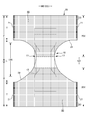
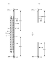
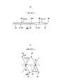
- FIG. 1 is a sectional view taken along the line AA of FIG. It is a cross-sectional view of BB of FIG. It is a plan view (outer surface side) of the pants type disposable diaper in the unfolded state.
- A) is a sectional view taken along the line CC of FIG.
- FIG. 7B is a sectional view taken along the line EE of FIG.
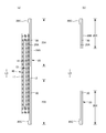
- (A) is a plan view of a main part of the expansion / contraction region
- (b) is a sectional view taken along line DD of (a)
- (c) is a sectional view taken in a mounted state
- (d) is a sectional view taken in a natural length state.
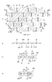
- It is a top view which shows various shapes of a sheet joint part.
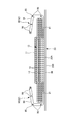
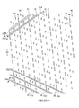
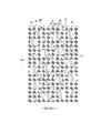
- It is a top view of the expansion and contraction area in the expanded state.
- (A) is a cross-sectional view taken along the line DD of FIG. 12, and (b) is a cross-sectional view taken along the line in the natural length state. It is a top view of the expansion and contraction area in the expanded state. It is a top view which shows the main part of the expansion and contraction area in an expanded state in an enlarged manner. It is a top view which shows the main part of the expansion and contraction region of a natural length state in an enlarged manner. It is sectional drawing which shows roughly the cross section of the main part of the exterior body extended to some extent. It is sectional drawing which shows roughly the cross section of the main part of the exterior body extended to some extent.
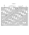
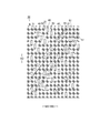
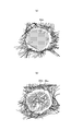
- (A) is a trace view of a plan photograph of a sheet joint formed in the first welded form
- (b) is a trace view of a plan photograph of a sheet joint formed in the third welded form.
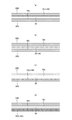
- It is the schematic of the ultrasonic sealing apparatus. It is a top view which shows the main part of the expansion and contraction area in an expanded state in an enlarged manner. It is a top view which shows the main part of the expansion and contraction region of a natural length state in an enlarged manner. It is sectional drawing which shows typically the elastic sheet expansion and contraction structure.
- (A) is a plan view of a main part of a non-stretchable region
- (b) is a sectional view taken along line DD of (a)
- (c) is a sectional view taken in a mounted state
- (d) is a sectional view taken in a natural length state. It is a main part plan view of a non-stretchable region.
- the dotted pattern portion in the figure shows an adhesive as a joining means for joining the constituent members located on the front side and the back side, and is a solid, bead, curtain, summit or spiral coating of hot melt adhesive, or
- the fixed portion of the elastic member is formed by pattern coating (transfer of hot melt adhesive by the letterpress method) or by coating the elastic member on the outer peripheral surface of the elastic member such as comb gun or sure wrap coating instead of or together with this. It is a thing.
- the hot melt adhesive include EVA type, adhesive rubber type (elastomer type), olefin type, polyester / polyamide type and the like, but they can be used without particular limitation.
- a means by welding materials such as a heat seal and an ultrasonic seal can also be used.
- non-woven fabric in the following description, a known non-woven fabric can be appropriately used depending on the site and purpose.
- the constituent fibers of the non-woven fabric include olefin-based fibers such as polyethylene and polypropylene, polyester-based and polyamide-based synthetic fibers (including single-component fibers and composite fibers such as core sheaths), as well as recycled rayon and cupra. Fibers, natural fibers such as cotton, and the like can be selected without particular limitation, and these can be mixed and used. In order to increase the flexibility of the non-woven fabric, it is preferable that the constituent fibers are crimped fibers.
- the non-woven fabric generally has a short fiber non-woven fabric, a long fiber non-woven fabric, a spunbond non-woven fabric, a melt blown non-woven fabric, a spunlace non-woven fabric, a thermal bond (air-through) non-woven fabric, and a needle punch depending on the fiber length, the sheet forming method, the fiber bonding method, and the laminated structure.
- Laminated non-woven fabric means that it is manufactured as an integral non-woven fabric including all layers and fiber-bonding processing is performed over all layers, and a plurality of separately manufactured non-woven fabrics are attached by a joining means such as a hot melt adhesive. Does not include combined items.
- FIGS. 1 to 6 show pants-type disposable diapers.
- the symbol LD vertical direction
- WD indicates the width direction.
- This pants-type disposable diaper (hereinafter, also simply referred to as a diaper) has an outer body 20 forming a front body F and a back body B, and an inner body 10 fixed and integrated to the inner surface of the outer body 20.
- the interior body 10 is formed by interposing an absorber 13 between the liquid-permeable top sheet 11 and the liquid-impermeable sheet 12.
- a joining means such as a hot melt adhesive
- the waist opening and the left and right sides are formed by folding at the center of the front-rear direction LD (longitudinal direction), which is the boundary between the two, and joining the both side portions to each other by heat welding or hot melt adhesive to form the side seal portion 21.
- LD longitudinal direction
- the interior body 10 has a structure in which an absorber 13 is interposed between a top sheet 11 and a liquid-impermeable sheet 12 made of polyethylene or the like, and has a top. It absorbs and retains the excrement liquid that has passed through the sheet 11.
- the planar shape of the interior body 10 is not particularly limited, but it is generally substantially rectangular as shown in FIG.
- a perforated or non-perforated non-woven fabric, a porous plastic sheet, or the like is preferably used as the top sheet 11 that covers the front side (skin side) of the absorber 13.
- liquid-impermeable sheet 12 that covers the back side (non-skin contact side) of the absorber 13
- a liquid-impermeable plastic sheet such as polyethylene or polypropylene
- a microporous sheet obtained by melting and kneading an inorganic filler in an olefin resin such as polyethylene or polypropylene to form a sheet and then stretching it in a uniaxial or biaxial direction can be preferably used.
- the absorber 13 is basically a known material, for example, a stack of pulp fibers, an aggregate of filaments such as cellulose acetate, or a non-woven fabric, and a highly absorbent polymer is mixed or fixed as necessary. Can be used.
- the absorber 13 can be wrapped with a wrapping sheet 14 having liquid permeability and liquid retention, such as crepe paper, if necessary, in order to retain the shape and polymer.
- the shape of the absorber 13 is formed in a substantially hourglass shape having a constricted portion 13N narrower than both front and rear sides in the crotch portion.
- the dimensions of the constricted portion 13N can be appropriately determined, but the length of the constricted portion 13N in the front-rear direction can be about 20 to 50% of the total length of the diaper, and the width of the narrowest portion is 40 of the total width of the absorber 13. It can be about 60%.
- the planar shape of the interior body 10 is substantially rectangular, the portion of the interior body 10 corresponding to the constricted portion 13N of the absorber 13 does not have the absorber 13.
- the absorber side portion 17 is formed.
- the liquid impermeable sheet 12 is folded back together with the top sheet 11 on both sides of the absorber 13 in the width direction.
- the liquid permeable sheet 12 it is desirable to use an opaque sheet so that brown color such as defecation and urine does not appear.
- the opacity a plastic in which pigments such as calcium carbonate, titanium oxide, zinc oxide, white carbon, clay, talc, and barium sulfate and a filler are added and formed into a film is preferably used.
- Three-dimensional gathers 90 that fit around the legs are formed on both sides of the interior body 10.
- the three-dimensional gather 90 has a fixed portion 91 fixed to the side portion of the back surface of the interior body 10, and the interior body 10 from the fixed portion 91 via the side of the interior body 10.
- the hot melt adhesive 95b or the like is applied to the side of the surface (top sheet 11 in the illustrated example) of the interior body 10. It has an inverted portion 93 formed by being fixed, and a free portion 94 formed so as not to be fixed between the inverted portions 93.
- Each of these parts is formed of a gather sheet 95 made by folding a sheet such as a non-woven fabric into a double sheet.
- the gather sheet 95 is attached to the entire interior body 10 in the front-rear direction, the inverted portion 93 is provided on the front side and the rear side of the non-absorbent body side portion 17, and the free portion 94 is provided on both front and rear sides of the non-absorbent body side portion 17. It has been postponed.
- a gather elastic member 96 is arranged at the tip of a free portion or the like. The gather elastic member 96 is for raising the free portion 94 by the elastic contraction force as shown in FIG. 5 in the product state.
- the fixed structure of the gather elastic member 96 and the gather sheet 95 is not particularly limited, and as in the examples shown in FIGS. 5 and 6, for example, except for the lodging portion 93, the gather elastic member 96 is located at the position of the gather elastic member 96 via a hot melt adhesive.
- the gather elastic member 96 is adhesively fixed to the gather sheet 95 and the facing surfaces of the gather sheet 95 are joined, there is no hot melt adhesive at the position of the gather elastic member 96 in the inverted portion 93, and therefore the gather elasticity.
- a structure can be adopted in which the member 96 and the gather sheet 95 are not adhered to each other, and the facing surfaces of the gather sheet 95 are not joined at the position where the gather elastic member 96 is held.
- the gather elastic member 96 commonly used materials such as styrene rubber, olefin rubber, urethane rubber, ester rubber, polyurethane, polyethylene, polystyrene, styrene butadiene, silicone, and polyester can be used. Further, in order to make it difficult to see from the outside, it is preferable to dispose of the thickness at 925 dtex or less, the tension at 150 to 350%, and the interval at 7.0 mm or less. As the gather elastic member 96, in addition to the elongated shape as shown in the illustrated example, a tape shape having a certain width can also be used.
- non-woven fabrics can be used as the gather sheet 95, but in particular, it is preferable to use a non-woven fabric having a low basis weight and excellent breathability in order to prevent stuffiness. Further, regarding the gather sheet 95, in order to prevent the permeation of urine and the like, prevent fogging, and enhance the feel (dry feeling) to the skin, silicone-based, paraffin metal-based, alkylchromic chloride-based water repellent, etc. It is desirable to use a water-repellent treated non-woven fabric coated with.
- the back surface of the interior body 10 is joined to the inner surface of the exterior body 20 by a hot melt adhesive or the like in the inner / outer fixed region 10B (diagonal line region).
- the inside / outside fixed region 10B can be appropriately defined and can be almost the entire width direction WD of the interior body 10, but it is preferable that both ends in the width direction are not fixed to the exterior body 20.
- the exterior body 20 has at least a waist circumference T of the front body F and a waist circumference T of the back body B, and in the illustrated example, between the waist circumference T of the front body F and the waist circumference T of the back body B. It further has an intermediate portion L which is a range in the front-rear direction of. In the crotch portion of the exterior body 20, the side edge of the exterior body 20 may be located on the center side in the width direction of the side edge of the interior body 10, or may be located on the outside in the width direction.
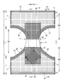
- the exterior body 20 of the illustrated example as shown in FIGS. 2 and 4 to 6, except for the middle portion L in the front-rear direction, between the first sheet layer 20A and the second sheet layer 20B.
- the elastic sheet 30 is interposed, and as shown in FIG. 9, the first sheet layer 20A and the second sheet layer 20B penetrate the elastic sheet 30 at a large number of sheet joints 40 arranged at intervals. It has an elastic sheet telescopic structure 20X joined through a joining hole 31 to be joined. Then, the region having the elastic sheet expansion / contraction structure is contracted in the width direction due to the contraction of the elastic sheet 30 and is expandable in the width direction (that is, the expansion / contraction direction ED becomes the width direction WD of the diaper). Have.
- the planar shape of the exterior body 20 is formed by concave leg circumference lines 29 so that both side edges in the width direction of the intermediate portion L form leg openings, respectively, and has a shape similar to an hourglass as a whole.
- the exterior body 20 may be individually formed by the front body F and the back body B, and may be arranged so as to be separated from each other in the front-rear direction LD of the diaper at the crotch portion.
- the form shown in FIGS. 1 and 2 is a form in which the elastic sheet telescopic structure 20X extends to the waist end portion 23, but when the elastic sheet telescopic structure 20X is used for the waist end portion 23, the waist end portion 23 If necessary, such as insufficient tightening, the waist end 23 is not provided with the elastic sheet elastic structure 20X as shown in FIGS. 7 and 8, and is expanded and contracted by the conventional elongated waist elastic member 24.
- a structure can also be provided.
- the waist elastic member 24 is an elongated elastic member such as a plurality of elastic threads arranged at intervals in the front-rear direction LD, and gives an elastic force so as to tighten around the waist of the body.
- the waist elastic members 24 are not substantially arranged as a bundle at close intervals, but are three or more at intervals of about 3 to 8 mm in the front-rear direction so as to form a predetermined expansion / contraction zone. , Preferably 5 or more are arranged.
- the elongation rate at the time of fixing the waist elastic member 24 can be appropriately determined, but in the case of a normal adult, it can be about 230 to 320%.
- thread rubber is used in the illustrated example, but other elongated elastic members such as flat rubber may be used.
- an elastic sheet 30 may be provided at the waist end 23, and an elongated waist elastic member 24 may be provided at a position overlapping the elastic sheet 30 to form an elastic structure composed of both elastic members.
- the edge portion of the leg opening in the exterior body 20 is not provided with the elongated elastic member extending along the leg opening, but at a position overlapping with the elastic sheet 30 in the edge portion or the edge.
- An elongated elastic member may be provided instead of the elastic sheet 30 of the portion.
- the elastic sheet elastic structure 20X is not provided in the intermediate portion L between the waist circumference T of the front body F and the waist circumference T of the back body B, or the front body.
- An elastic sheet elastic structure 20X is continuously provided in the front-rear direction LD from the inside of the waist circumference T of F through the middle portion L to the inside of the waist circumference T of the back body B, or either the front body F or the back body B is provided.
- Appropriate deformation is also possible, such as providing an elastic sheet telescopic structure 20X only on the surface.
- the region of the exterior body 20 having the elastic sheet telescopic structure 20X has a stretchable region that can be stretched in the width direction WD.
- the elastic sheet 30 is contracted in the width direction WD due to the contraction force, and can be expanded in the width direction WD. More specifically, in a state where the elastic sheet 30 is extended in the width direction WD, the elastic sheet 30 is separated from each other in the width direction WD and the front-rear direction LD (direction LD orthogonal to the expansion / contraction direction) orthogonal to the width direction WD.
- the elastic sheet elastic structure 20X is formed by joining the first sheet layer 20A and the second sheet layer 20B through the joint hole 31 to form a large number of sheet joint portions 40, and the elastic sheet 30 is formed in the elastic region 80.
- the sheet joint 40 is arranged so that the first sheet layer 20A and the second sheet layer 20B are contracted by the contraction force of the elastic sheet 30 to form the contraction folds 25, while remaining uninterrupted in the width direction WD. Thereby, such elasticity can be imparted.
- the stretchable region 80 expands in the direction in which the first sheet layer 20A and the second sheet layer 20B between the sheet joints 40 are separated from each other as shown in FIGS.
- the contraction folds 25 extending in the direction LD are formed, and the contraction folds 25 are extended but remain even in the wearing state in which the contraction folds 25 extend in the width direction WD to some extent.
- the first sheet layer 20A and the second sheet layer 20B are not joined to the elastic sheet 30 except between the first sheet layer 20A and the second sheet layer 20B at least in the sheet joining portion 40.
- FIG. 9C assuming a mounted state and FIG.
- the elastic sheet 30 Even if the edge of the joint hole 31 is separated from the outer peripheral edge of the sheet joint 40 in the expansion / contraction direction and the ventilation hole 33 (gap) is opened, and the material of the elastic sheet 30 is a non-perforated film or sheet, this passage is achieved. Breathability is added by the pores 33.
- the elastic sheet 30 has a portion 32 linearly continuous along the width direction WD, in the natural length state, the joint hole 31 is narrowed due to further contraction of the elastic sheet 30, and the joint hole 31 is narrowed. A gap is hardly formed between the 31 and the sheet joint 40, and when the elastic sheet 30 does not have a linearly continuous portion along the width direction WD, the ventilation hole 33 remains.
- the maximum elongation of the WD in the width direction of the expansion / contraction region 80 is 190% or more (preferably 200 to 220%).
- the maximum elongation of the stretchable region 80 is substantially determined by the stretch ratio of the elastic sheet 30 at the time of manufacture, but based on this, it is lowered by a factor that inhibits the shrinkage of the WD in the width direction.
- the main factor of such an inhibitory factor is the ratio of the length L of the sheet joint 40 to the unit length in the width direction WD, and the larger the ratio, the lower the maximum elongation.
- the maximum elongation of the expansion / contraction region 80 can be adjusted by the area ratio of the sheet joint 40.
- the elongation stress of the expansion / contraction region 80 is mainly the width of the elastic sheet 30 when the elastic sheet 30 has a portion 32 linearly continuous along the width direction WD as shown in the example shown in FIG. It can be adjusted by the sum of the orthogonal dimensions 32w (equal to the joint hole spacing 31d) of the portions 32 (see FIG. 9A) that are linearly continuous along the direction WD.
- the elastic sheet 30 does not have a portion linearly continuous along the width direction WD as in the example shown in FIG. 11 and the example shown in FIG. 15, the elongation stress of the expansion / contraction region 80 is increased.
- the area ratio of the sheet joint 40 in the expansion / contraction region 80 and the area of each sheet joint 40 can be appropriately determined, but usually, it is preferably within the following range.
- Area of sheet joint 40 0.14 to 3.5 mm 2 (particularly 0.14 to 1.0 mm 2 )
- Area ratio of sheet joint 40 1.8 to 19.1% (especially 1.8 to 10.6%)
- the maximum elongation and elongation stress of the expansion / contraction region 80 can be adjusted by the area of the sheet joint 40. Therefore, as shown in FIG. 7, a plurality of regions having different area ratios of the sheet joint 40 are formed in the expansion / contraction region 80. It can be provided and the fit can be changed according to the part.
- the edge region 82 of the leg opening has a higher area ratio of the sheet joint 40 than the other regions, and therefore has a weak elongation stress and is a region that flexibly expands and contracts.
- the shapes of the individual sheet joints 40 and the joint holes 31 in their natural lengths can be appropriately determined, but are perfect circles, ellipses, triangles, rectangles (see FIGS. 9, 11, and 15), and diamonds (see FIGS. 9, 11, and 15). It can be a polygon such as 10 (b)), a convex lens shape (see FIG. 10 (a)), a concave lens shape (see FIG. 10 (c)), a star shape, a cloud shape, or any other shape.
- the dimensions of the individual sheet joints are not particularly limited, but the maximum length 40y (approximately equal to the dimension 31y in the orthogonal direction of the joint hole 31) is 0.5 to 3.0 mm, particularly 0.7 to 1.1 mm.
- the maximum width of 40x is preferably 0.1 to 3.0 mm, and particularly preferably 0.1 to 1.1 mm in the case of a shape long in the direction XD orthogonal to the expansion / contraction direction.
- the arrangement pattern of the sheet joint portion 40 of the expansion / contraction region 80 is not particularly limited, and any pattern (see, for example, Patent Documents 1 to 8) can be adopted, and in particular, the example shown in FIG. 9 and the example shown in FIG. 11 And, as in the example shown in FIG. 15, it is preferable that non-joining bands having continuous portions having no sheet joining portion exist in an oblique lattice pattern.
- the illustrated example shows a particularly preferable example, and the stretchable region 80 has an acute angle (with respect to the stretchable direction ED) as non-joint bands 51 and 52 in which the portions having no sheet joint portion 40 are continuous in the expanded state.
- the first non-joint band 51 that is linearly continuous along the first direction 51d intersecting the acute angle side crossing angle ⁇ 1) exists repeatedly at intervals in the direction orthogonal to the first direction 51d. Further, a large number of sheet joint portions 40 and joint holes 31 are provided at intervals between the adjacent first non-joining bands 51 in the expansion / contraction region 80. And characteristically, the unit structure including a plurality of first non-joining bands 51 having different first widths 51w determined as widths in the direction orthogonal to the first direction 51d is orthogonal to the first direction 51d in the expansion / contraction region 80. It exists repeatedly in the direction.
- the unit structure including the plurality of first non-joining bands 51 having different first widths 51w repeatedly exists in the direction orthogonal to the first direction 51d in the elastic region 80, the inside of the first non-joining band 51
- a similar width change of magnitude relation is formed in the continuous portion of the elastic sheet 30 of the above. That is, if the width 51w of the first non-joining band 51 is narrow, the width of the continuous portion of the internal elastic sheet 30 is also narrow, and if the width 51w of the first non-joining band 51 is wide, the continuous portion of the internal elastic sheet 30 is continuous. The width of the part also becomes wider.
- the size of the contraction folds 25 in the first non-joining band 51 changes according to the first width 51w of the first non-joining band 51, and therefore, the diagonal stripes due to the influence of the contraction folds 25. The pattern will appear more clearly.
- the above-mentioned unit structure is not limited by the degree of the size of the width 51w as long as it includes a plurality of first non-joining bands 51 having different first widths 51w, but the first unit structure in the first non-joining band 51
- the width 51w is preferably 1.2 to 60 times larger and 0.01 to 0.8 times smaller than the first non-joining band 51 having the nearest first width 51w.
- the first width 51w in all the first non-joining bands 51 may be different and is shown.
- the first width 51w of some of the plurality of first non-joining bands 51 may be different from the first width 51w of the other single or plurality of first non-joining bands 51.
- the maximum value of the first width 51w in the first non-joining zone 51 is the maximum value of the width in the direction orthogonal to the continuous direction in all the non-joining zones 51 and 52 having different and common inclination directions.
- the diagonal stripe pattern due to the contraction fold 25 of the first non-joining band 51 and the continuous portion of the elastic sheet 30 inside the contraction fold 25 becomes more strongly visible, which is preferable.
- the maximum value of the first width 51w in the first non-joining band 51 can be appropriately determined, but is 1.2 to 60 times that of the nearest first non-joining band 51 having the first width 51w. Is preferable.
- the width of all the non-joining bands 51 and 52 including the first non-joining band 51 is not limited in the direction orthogonal to the continuous direction, but is usually within the range of 0.02 to 5 mm. Is preferable. Needless to say, the width of the non-joining bands 51 and 52 in the direction orthogonal to the continuous direction is the first width 51w in the first non-joining band 51, which is a linearly continuous portion. Because it is the same width.
- the first spacing 51s which is determined as the spacing in the direction orthogonal to the first direction 51d in the adjacent first non-joining zones 51, can be appropriately determined. Therefore, the first interval 51s may be the same as the first width 51w in the adjacent first non-joining zone 51, may be wider, or may be narrower. As one preferable example, in the unit structure, the maximum value of the first width 51w in the first non-joining zone 51 may be smaller than the maximum value of the first interval 51s. By forming a wide interval portion in the unit structure in this way, the diagonal stripe pattern due to the contraction fold 25 of the first non-joint band 51 and the continuous portion of the elastic sheet 30 inside the contraction fold 25 becomes more strongly visible. ..
- the maximum value of the first width 51w in the first non-joining zone 51 can be appropriately determined, but it is preferably 0.01 to 9 times the maximum value of the first interval 51s.
- the distance between all the non-joining zones 51 and 52 including the first non-joining zone 51 in the direction orthogonal to the continuous direction is not particularly limited, but is usually within the range of 0.3 to 50 mm. Is preferable.
- the interval in the direction orthogonal to the continuous direction in the non-joining zones 51 and 52 is the first interval 51s in the first non-joining zone 51, which is equal to the continuous direction. ..
- the non-joint bands 51 and 52 are linearly continuous along the second direction 52d intersecting the acute angle (acute angle side intersection angle ⁇ 2) with respect to the extension / contraction direction ED other than the first direction 51d.
- the two non-joining bands 52 may repeatedly exist at intervals in the direction orthogonal to the second direction 52d, or the second non-joining band 52 may not exist.
- One preferable form having the second non-joining band 52 is that the non-joining bands 51 and 52 are formed in a diagonal grid pattern in the expansion / contraction region 80, and the first non-joining band 51 is a diagonal grid-like non-joining band.
- the second non-joint band 52 is a portion of the diagonal grid-like non-joint bands 51 and 52 that is continuous in the other direction.
- the positive and negative of the inclination with respect to the expansion / contraction direction ED are opposite to each other.
- the expansion / contraction region 80 is in the expanded state.
- the acute-angled crossing angles ⁇ 1 and ⁇ 2 with respect to the expansion / contraction direction ED in the first direction 51d and the second direction 52d are 5 to 45 degrees, particularly 10 to 30, so that sufficient elasticity in the expansion / contraction region 80 is ensured. Can be done.
- the diagonal stripe pattern along the diagonal direction of the second non-joining band 52 is more strongly visually recognized in the same stretchable region 80, the contraction fold 25 of the first non-joining band 51 and the continuous portion of the elastic sheet 30 inside the contraction fold 25
- the diagonal stripe pattern may become inconspicuous. Therefore, when the second non-joining band 52 is provided as in the example shown in FIG. 15, the second width 52w determined as the width in the direction orthogonal to the second direction in the second non-joining band 52 is all the same or is the same. It is desirable to arrange the sheet joint portion 40 so as not to have the second non-joint band 52. As a result, in the expansion / contraction region 80, the diagonal stripe pattern due to the contraction fold 25 of the first non-joining band 51 and the continuous portion of the elastic sheet 30 inside the contraction fold 25 becomes more strongly visible.
- the sheet joints 40 are aligned in the first direction 51d between the adjacent first non-joint bands 51.
- all the sheet joints 40 expand and contract.
- the acute angle side intersection angle ⁇ 3 in the longitudinal direction with respect to the direction orthogonal to the direction ED is within 10 degrees and the maximum dimension 40e of the expansion / contraction direction ED is 0.1 to 0.4 mm, the first non-joint zone is formed. It is preferable because the size of the expansion / contraction direction ED of 51 can be secured larger and the decrease in elasticity can be suppressed.
- the unit structure includes a wide first non-joining band 51 having a maximum first width 51w and a narrow first non-joining band 51 having a narrower first width 51w.
- the acute angle side intersection angle in the longitudinal direction with respect to the second direction 52d is within 5 degrees between the adjacent wide first unjoined bands 51.
- the sheet joints 40 having an elongated shape with a maximum dimension 40f in the direction orthogonal to the longitudinal direction of 0.1 to 0.4 mm are aligned in the first direction 51d at intervals.
- the acute angle side crossing angle ⁇ 3 in the longitudinal direction with respect to the first direction 51d is 45 degrees or more, and the maximum dimension 40 g in the direction orthogonal to the longitudinal direction is 0.
- the sheet joints 40 having an elongated shape of 1 to 0.4 mm are arranged at intervals in the first direction 51d. Due to the shape and arrangement of the sheet joint 40 in this way, the shrinkage fold 25 of the first non-joint band 51 and the continuous portion of the elastic sheet 30 inside the shrinkage fold 25 are particularly visually emphasized with a smaller area of the sheet joint 40. Become so.
- the row of the sheet joints 40 (rows in the continuous direction of the non-joining bands 51 and 52) located between the adjacent non-joining bands 51 and 52 may be one row or a plurality of rows. Further, although the spacing between the sheet joints 40 in the row direction is preferably regular, not all spacings need to be constant, and some spacings may be different.
- a non-stretchable region 70 can be provided on at least one side of the stretchable region 80 in the width direction in the region of the exterior body 20 having the elastic sheet stretchable structure 20X.
- the non-stretchable region 70 means that the maximum stretch in the stretch direction is 120% or less.
- the maximum elongation of the non-stretchable region 70 is preferably 110% or less, and more preferably 100%.
- the arrangement of the stretchable region 80 and the non-stretchable region 70 can be appropriately determined.
- the non-stretchable region 70 is defined as the non-stretchable region 70) (preferably including almost the entire inner / outer fixed region 10B).
- the non-stretchable region 70 can be provided from the region that overlaps with the absorber 13 to the region that does not overlap with the absorber 13 located in the width direction WD or the front-back direction LD, and the non-stretchable region is provided only in the region that does not overlap with the absorber 13. 70 can also be provided.
- each sheet joint 40 in the non-stretchable region 70 is not particularly limited, and can be appropriately selected from the same shapes as those described in the section of the stretchable region 80.
- the area ratio of the sheet joint 40 and the area of each sheet joint 40 in the non-stretchable region can be appropriately determined, but in the normal case, the area of each sheet joint 40 is small if it is within the following range. Moreover, it is preferable that the non-stretchable region 70 does not become hard due to the low area ratio of the sheet joint portion 40.
- Area of sheet joint 40 0.10 to 0.75 mm 2 (particularly 0.10 to 0.35 mm 2 )
- Area ratio of sheet joint 40 4 to 13% (especially 5 to 10%)
- the non-stretchable region 70 may be formed by densely arranging the sheet joints 40 so that the first sheet layer 20A and the second sheet layer 20B do not shrink due to the contraction force of the elastic sheet 30 to form folds. it can.
- Specific examples of the method for forming the non-stretchable region 70 include those described in Patent Documents 3 to 6. 25 and 26 show an example of the non-stretchable region 70 described in Patent Document 6.
- the joint holes 31 are arranged in a staggered pattern in a dense arrangement to some extent, and the elastic sheet 30 is continuous with the expansion / contraction direction ED, but due to the presence of the joint holes 31, it is linear along the expansion / contraction direction ED. It does not have a continuous part.
- the ventilation holes 33 are opened with a size that is almost the same in both the natural length state and the unfolded state.
- the joining means of the first sheet layer 20A and the second sheet layer 20B in the sheet joining portion 40 is not particularly limited.
- the first sheet layer 20A and the second sheet layer 20B in the sheet bonding portion 40 may be bonded by a hot melt adhesive or by a bonding means such as heat sealing or ultrasonic sealing. ..
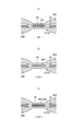
- the form in which the sheet joining portion 40 is formed by material welding is the first in the sheet joining portion 40.
- a first welded form in which the first sheet layer 20A and the second sheet layer 20B are joined only by a molten solidified product 20m of at least one of the first sheet layer 20A and the second sheet layer 20B (FIG. 18 (a)).
- a second welded form in which the first sheet layer 20A and the second sheet layer 20B are joined only by the molten solidified product 30 m of all or most or part of the elastic sheet 30 at the sheet joining portion 40 (FIG. 18 (FIG. 18).
- b)) or a third welded form in which both of these are combined may be used, but the second and third welded forms are preferable.
- the first sheet layer consisting of a part of the molten solidified product 20 m of the first sheet layer 20A and the second sheet layer 20B and the molten solidified product 30 m of all or most of the elastic sheet 30 at the sheet joint 40. It is a form in which 20A and the second sheet layer 20B are joined.
- the elastic sheet 30 shown in white is shown between the melt-solidified 20 m of the fibers of the first sheet layer 20A or the second sheet layer 20B shown in black.
- the elastic sheet 30 is formed between the melt-solidified 20 m of the fibers of the first sheet layer 20A or the second sheet layer 20B. No melted solidified material is found.
- the first sheet layer 20A and the second sheet layer 20A and the second sheet layer 20A and the second sheet layer 20A and the second sheet layer 20A and the second sheet layer 20A and the second sheet layer 20B use at least one of at least one of the 1st sheet layer 20A and the 2nd sheet layer 20B as an adhesive.
- the sheet layer 20B it is preferable that a part of the first sheet layer 20A and the second sheet layer 20B is not melted because the sheet bonding portion 40 is not hardened.
- the core (the core of all the fibers of the sheet joint 40 is required so that a part of the first sheet layer 20A and the second sheet layer 20B does not melt. Not only the core of the composite fiber but also the central part of the single component fiber remains), but the peripheral part (including not only the sheath of the composite fiber but also the surface layer side part of the single component fiber) is in a melted form or a part. The fibers do not melt at all, but the remaining fibers are all melted or the core remains but the surrounding part is melted.
- the peel strength becomes high.
- the first sheet layer 20A is under the condition that the melting point of at least one of the first sheet layer 20A and the second sheet layer 20B is higher than the melting point of the elastic sheet 30 and the heating temperature at the time of forming the sheet joint 40. It can be manufactured by sandwiching the elastic sheet 30 between the second sheet layer 20B, pressurizing and heating the portion to be the sheet joint portion 40, and melting only the elastic sheet 30.
- the third welded form between the first sheet layer 20A and the second sheet layer 20B under the condition that the melting point of at least one of the first sheet layer 20A and the second sheet layer 20B is higher than the melting point of the elastic sheet 30. It can be produced by sandwiching the elastic sheet 30 and pressurizing and heating the portion to be the sheet joint portion 40 to melt at least one of the first sheet layer 20A and the second sheet layer 20B and the elastic sheet 30.
- the melting point of the elastic sheet 30 is preferably about 80 to 145 ° C., and the melting points of the first sheet layer 20A and the second sheet layer 20B are about 85 to 190 ° C., particularly about 150 to 190 ° C.
- the difference between the melting points of the first sheet layer 20A and the second sheet layer 20B and the melting points of the elastic sheet 30 is preferably about 60 to 90 ° C.
- the heating temperature is preferably about 100 to 150 ° C.
- the molten solidified product 30 m of the elastic sheet 30 is a sheet joint portion as shown in FIG. 19 (c).
- the first sheet layer 20A and the second sheet layer 20B in No. 40 may permeate between the fibers over the entire thickness direction, but as shown in FIG. 19A, they permeate between the fibers to the middle in the thickness direction, or As shown in FIG. 19B, the flexibility of the sheet joint 40 is higher in the form in which the fibers of the first sheet layer 20A and the second sheet layer 20B hardly permeate.
- FIG. 21 shows an example of an ultrasonic sealing device suitable for forming the second welding form and the third welding form.
- this ultrasonic sealing device when forming the sheet joint 40, the first sheet layer 20A, between the anvil roll 60 having the protrusion 60a formed in the pattern of the sheet joint 40 on the outer surface and the ultrasonic horn 61, The elastic sheet 30 and the second sheet layer 20B are fed.
- the feed transfer speed of the elastic sheet 30 on the upstream side by the feed drive roll 63 and the nip roll 62 slower than the transfer speed after the anvil roll 60 and the ultrasonic horn 61
- the feed drive roll 63 and the nip roll 62 The elastic sheet 30 is extended to a predetermined elongation rate in the MD direction (machine direction, flow direction) by the path from the nip position by the anvil roll 60 to the seal position by the ultrasonic horn 61.
- the elongation rate of the elastic sheet 30 can be set by selecting the speed difference between the anvil roll 60 and the feed drive roll 63, and can be set to, for example, about 300% to 500%.
- the joint hole 31 is formed from the portions on both sides in the expansion / contraction direction by the joint holes 31 as shown in FIGS. 9A, 12 and 13. Since it will be cut and lose the support on both sides in the contraction direction, it contracts until the center side of the LD in the direction orthogonal to the expansion / contraction direction ED is balanced with the center side in the expansion / contraction direction within the range where continuity in the direction orthogonal to the contraction direction can be maintained. Then, the joint hole 31 expands in the expansion / contraction direction ED.
- the constituent materials of the first sheet layer 20A and the second sheet layer 20B can be used without particular limitation, but are preferably breathable. Therefore, it is preferable to use a non-woven fabric from these viewpoints and from the viewpoint of flexibility. When a non-woven fabric is used, the texture is preferably about 10 to 25 g / m 2 . Further, a part or all of the first sheet layer 20A and the second sheet layer 20B may be a pair of layers in which one material is folded back and opposed to each other. For example, as shown in the illustrated figure, in the waist end portion 23, the constituent material located on the outside is the second sheet layer 20B, and the folded portion 20C formed by folding back toward the inner surface side at the waist opening edge is used as the first sheet layer 20A.
- the constituent material located inside is the first sheet layer 20A and the constituent material located outside is the second sheet layer 20B, and the elastic sheet 30 is placed between them. Can be intervened.
- the constituent material of the first sheet layer 20A and the constituent material of the second sheet layer 20B are individually provided over the entire front-rear direction LD, and the constituent material of the first sheet layer 20A and the second sheet are not folded back.
- An elastic sheet 30 can also be interposed between the constituent members of the layer 20B.
- the elastic sheet 30 is not particularly limited, and may be an elastic non-woven fabric as long as it is a sheet made of a thermoplastic resin having elasticity by itself. Further, as the elastic sheet 30, in addition to a non-perforated sheet, a sheet having a large number of holes and slits formed for ventilation can also be used.
- the tensile strength in the width direction WD (extension direction ED, MD direction) is 8 to 25 N / 35 mm
- the tensile strength in the front-rear direction LD (direction XD, CD direction orthogonal to the extension direction) is 5 to 20 N / 35 mm, and the width direction.
- the elastic sheet 30 has a tensile elongation of 450 to 1050% in the WD and a tensile elongation of 450 to 1400% in the front-rear LD.
- the thickness of the elastic sheet 30 is not particularly limited, but is preferably about 20 to 40 ⁇ m.
- the ventilation hole 33 is a portion where the edge of the joint hole 31 is formed apart from the outer peripheral edge of the sheet joint portion 40 in the expansion / contraction direction ED, the ventilation hole 33 is deformed by the extension of the elastic sheet 30 and is in the expanded state. The closer it gets, the bigger it gets. Further, depending on the shape (for example, circular shape) of the sheet joint 40, the edge of the joint hole 31 and the outer peripheral edge of the sheet joint 40 may be in close contact with each other in the natural length state, and the ventilation hole 33 may not be formed.
- the joint holes 31 are extended in the expansion / contraction direction ED, so that ventilation holes 33 are opened at least on both sides of the expansion / contraction direction ED of the sheet joint portion 40. Since the ventilation holes 33 improve the air permeability, being visible to the user brings a functional aesthetic appearance to the product. Therefore, the color difference ⁇ E between the color of the outer surface of the elastic sheet 30 and the color of the outer surface of the first sheet layer 20A (lower sheet layer) is set to 30 or more, and the color of the outer surface of the elastic sheet 30 and the outer surface of the first sheet layer 20A are passed through. As shown in FIGS. 12 and 13, FIGS.
- the shape of the ventilation hole 33 is changed to the second sheet layer 20B (outer sheet layer) due to the difference from the color of the portion viewed from the pore 33. ) To make it easier to see.
- the color difference ⁇ E between the color of the outer surface 30s of the elastic sheet 30 and the color of the outer surface 20s of the first sheet layer 20A is particularly preferably 40 or more.
- the region where the color difference ⁇ E between the color of the outer surface 30s of the elastic sheet 30 and the color of the outer surface 20s of the first sheet layer 20A is 30 or more is the entire region having the elastic sheet elastic structure 20X. However, it may be a part of the region, for example, only the exposed portion exposed on the outer surface. However, it is desirable that the aesthetic improvement region is a region including the entire one or a plurality of ventilation holes 33 (preferably the joint holes 31).
- the aesthetic improvement region can be provided in only one of the stretchable region 80 and the non-stretchable region 70, or can be provided in both.
- the aesthetic improvement areas may be provided at a plurality of places at intervals, or the aesthetic improvement areas having different color differences may be provided at a plurality of places at intervals or adjacent to each other.
- the stretchable region 80 and the non-stretchable region may be provided with different color difference aesthetic improvement regions, or the waist end 23 region and other regions may be provided with different color difference aesthetic improvement regions.
- the pattern of the joint hole 31 is not particularly limited, but as in the examples shown in FIGS. 12 and 13, FIGS. 16 and 17, and 22 and 23, the portion having no sheet joint 40 is continuous. If the non-joining bands 51 and 52 are present in an oblique lattice pattern, the arrangement of the joining holes 31 is also the same. As a result, the elastic sheet 30 exists in a diagonal grid pattern (the first non-joint band 51 and the second non-joint band 52 diagonally intersect), which is easily visible due to the above-mentioned color difference, and the diagonal lattice shape is excellent. It is preferable because it gives an aesthetic appearance.
- one or both of the elastic sheet 30 and the first sheet layer 20A can be colored.
- the coloring method is not particularly limited, but when a single material is colored in multiple colors, printing or post-dyeing can be performed, and when the entire material is colored in a single color, printing or post-dyeing is adopted.
- a method of mixing a dye or a pigment with a raw material so-called dyeing.
- a non-woven fabric a non-woven fabric is formed by a stock-colored fiber colored by mixing a dye or a pigment with a stock solution before spinning). You can also.
- FIG. 24 (a) shows an example in which the colored layer 100 by printing is provided on the outer surface 30s of the elastic sheet 30, and FIG. 24 (b) shows an example in which the elastic sheet 30 is colored by the original coating.
- FIG. 24 (c) shows an example in which the colored layer 100 by printing is provided on the outer surface 20s of the first sheet layer 20A
- FIG. 24 (d) shows the first sheet layer 20A colored by the original coating.
- An example is shown.
- the case where the first sheet layer 20A is a non-woven fabric and the colored layer 100 is provided not only on the outer surface 20s of the first sheet layer 20A but also on the inside due to the penetration of ink. I'm assuming.
- the entire first sheet layer 20A in the thickness direction is colored, but the first sheet layer 20A is made of a laminated non-woven fabric, and a part of the layers (for example, a layer including the outer surface 20s) is used. ), It is also possible to color only a part in the thickness direction.
- the aesthetic improvement region may be colored, or a wider area including the aesthetic improvement region, for example, the entire material may be colored. Further, when a plurality of aesthetic areas are provided, different colors may be used for each aesthetic area.
- the color of the outer surface 30s of the elastic sheet 30 and the color of the outer surface 20s of the first sheet layer 20A can be appropriately determined.
- the coloring of the first sheet layer 20A has an L * value of CIELAB of 20 to 60 and an absolute value of at least one of the a * value and the b * value. Is 0 to 40, and the color of the outer surface 30s of the elastic sheet 30 is that the L * value of CIELAB is 50 to 90 and the absolute value of at least one of the a * value and the b * value is 0 to 40. preferable.
- the color of the outer surface 30s of the elastic sheet 30 is white or a light color close to white, and the color of the outer surface 20s of the first sheet layer 20A is the elastic sheet 30. Since the color is darker than that (the part of the dot pattern in the figure), the ventilation holes 33 are dark and the other parts are light and look like a mesh. That is, this color scheme is suitable when the outer surface of the product has a bright color tone because white or a light color close to white continues in a mesh pattern. Further, this color scheme can be realized only by coloring the first sheet layer 20A without coloring the elastic sheet 30 (that is, keeping the raw material color).
- the CIELAB L * value is 20 to 60
- the absolute value of at least one of the a * value and the b * value is 0 to 40
- the color of the outer surface 20s of the first sheet layer 20A preferably has an L * value of CIELAB of 50 to 90 and an absolute value of at least one of the a * value and the b * value of 0 to 40.
- the color of the outer surface 20s of the first sheet layer 20A is white or a light color close to white, and the color of the outer surface 30s of the elastic sheet 30 is white.
- the ventilation holes 33 are light in color, and the other parts are dark in color (dotted parts in the figure) and appear as a mesh. That is, this color scheme is suitable for dark or dark tones because the dark colors are continuous in a mesh pattern. It is also preferable that this color scheme can be realized only by coloring the elastic sheet 30 without coloring the first sheet layer 20A (that is, keeping the raw material color).
- the translucency of the second sheet layer 20B is as long as the color of the outer surface 30s of the elastic sheet 30 and the color of the portion of the outer surface 20s of the first sheet layer 20A seen through the ventilation holes 33 can be seen through the second sheet layer 20B.
- a non-woven fabric having a translucency (JIS method) defined in JIS L 1913: 2010 having a translucency of 50% or more, particularly 65% or more, has a shape of a vent 33. This is preferable because it provides excellent visibility.
- the second sheet layer 20B is preferably uncolored (that is, the raw material color remains), but may be colored.
- Front body and rear body mean the front and rear parts of the pants-type disposable diaper with the center in the front-back direction as the boundary, respectively.
- the crotch portion means a front-rear direction range including the center in the front-rear direction of the pants-type disposable diaper, and when the absorber has a constricted portion, it means the front-rear direction range of the portion having the constricted portion.
- Maximum elongation means the maximum value of elongation in the expansion / contraction direction ED (in other words, elongation in the expanded state in which the first sheet layer and the second sheet layer are expanded flat without shrinkage or slack), and is in the expanded state.
- the length is expressed as a percentage when the natural length is 100%.
- the "area ratio” means the ratio of the target portion to the unit area, and the target portion (for example, the sheet joint portion 40, the opening of the joint hole 31, the ventilation hole) in the target region (for example, the stretchable region 80 and the non-stretchable region 70). ) Is divided by the area of the target area and expressed as a percentage.
- the “area ratio” in the region having a stretchable structure means the area ratio in the expanded state. In a form in which a large number of target portions are provided at intervals, it is desirable to set the target area to a size that includes 10 or more target portions and obtain the area ratio.
- Elongation rate means the value when the natural length is 100%. For example, an elongation rate of 200% is synonymous with an elongation ratio of 2 times.
- ⁇ "Graining" is measured as follows. After pre-drying the sample or test piece, leave it in a test room or device under standard conditions (test location: temperature 23 ⁇ 1 ° C., relative humidity 50 ⁇ 2%) to bring it to a constant weight. Pre-drying refers to constant weight of a sample or test piece in an environment at a temperature of 100 ° C. It is not necessary to pre-dry the fibers having an official moisture content of 0.0%. A sample having a size of 100 mm ⁇ 100 mm is cut out from the test piece in a constant weight state using a sampling template (100 mm ⁇ 100 mm). The weight of the sample is measured and multiplied by 100 to calculate the weight per square meter, which is used as the index.
- the "thickness" of the absorber is the thickness measuring instrument of Ozaki Seisakusho Co., Ltd. (peacock, dial thickness gauge large type, model JB (measurement range 0 to 35 mm) or model K-4 (measurement range 0 to 50 mm)) Measure with the sample and the thickness measuring device horizontal.
- the "thickness" other than the above is automatically measured using an automatic thickness measuring device (KES-G5 handy compression measurement program) under the conditions of a load of 0.098 N / cm 2 and a pressurized area of 2 cm 2 .
- KS-G5 handy compression measurement program automatic thickness measuring device
- test piece has a rectangular shape with a width of 35 mm and a length of 80 mm. It means a value measured with an initial chuck interval (distance between marked lines) of 50 mm and a tensile speed of 300 mm / min.
- initial chuck interval distance between marked lines
- tensile speed 300 mm / min.
- AUTOGRAPH AGS-G100N manufactured by SHIMADZU can be used as the tensile tester.
- Elongation stress is defined by a tensile test in which the initial chuck interval (distance between marked lines) is 50 mm and the tensile speed is 300 mm / min according to JIS K7127: 1999 "Plastic-Test method for tensile properties”. , Means the tensile stress (N / 35 mm) measured when stretching in the elastic region, and the degree of stretching can be appropriately determined depending on the test object.
- the test piece is preferably rectangular with a width of 35 mm and a length of 80 mm or more, but if a test piece having a width of 35 mm cannot be cut out, a test piece is prepared with a width that can be cut out, and the measured value is measured with a width of 35 mm.
- the L * value, a * value and b * value of "CIELAB” shall be measured as follows according to JIS Z 8781-4 "Part 4: CIE 1976 L * a * b * color space”.
- the first sheet layer (lower sheet layer) and the elastic sheet are taken out in their respective states and used as a sample. Then, for example, using a measuring device such as X-Rite eXact Standard (measurement diameter: 1.5 mm) manufactured by X-Rite, a white reflection standard (white plate) is arranged on the inner surface of the sample in the unfolded state, and the sample is prepared.
- the measurement diameter of the measuring device is large with respect to the sheet joint and the joint interval, and it is not possible to measure only the portion of the first sheet layer (lower sheet layer) where there is no sheet joint, or there is no joint hole in the elastic sheet. If it is not possible to measure only the portion, a sample can be prepared using the same material as the product, and the L * value, a * value and b * value can be measured.
- the L * value, the a * value, and the b * value may be measured by pasting them side by side so that
- ⁇ E (( ⁇ L *) 2 + ( ⁇ a *) 2 + ( ⁇ b *) 2 ) 1/2
- Expanded state means a state in which it is deployed flat without shrinkage or slack.
- the dimensions of each part mean the dimensions in the unfolded state, not in the natural length state.
- test or measurement shall be performed in a test room or equipment under standard conditions (test location: temperature 23 ⁇ 1 ° C, relative humidity 50 ⁇ 2%). To do.
- the present invention includes pants-type disposable diapers as in the above example, various disposable diapers such as tape type and pad type, sanitary napkins, swimming, etc., as long as they have an elastic area to which the elastic sheet elastic structure can be applied. It can be used as an elastic member for all disposable wearable articles such as disposable wearable articles for playing in water.
Landscapes
- Health & Medical Sciences (AREA)
- Engineering & Computer Science (AREA)
- Animal Behavior & Ethology (AREA)
- General Health & Medical Sciences (AREA)
- Biomedical Technology (AREA)
- Heart & Thoracic Surgery (AREA)
- Vascular Medicine (AREA)
- Life Sciences & Earth Sciences (AREA)
- Veterinary Medicine (AREA)
- Epidemiology (AREA)
- Public Health (AREA)
- Dermatology (AREA)
- Mechanical Engineering (AREA)
- Textile Engineering (AREA)
- Absorbent Articles And Supports Therefor (AREA)
- Laminated Bodies (AREA)
- Professional, Industrial, Or Sporting Protective Garments (AREA)
- Orthopedics, Nursing, And Contraception (AREA)
Priority Applications (3)
| Application Number | Priority Date | Filing Date | Title |
|---|---|---|---|
| CN202080009394.0A CN113316439B (zh) | 2019-03-18 | 2020-02-21 | 伸缩部件和具有该伸缩部件的一次性穿着物品 |
| EP20773997.0A EP3906910B1 (en) | 2019-03-18 | 2020-02-21 | Elastic member and disposable wearable article having elastic member |
| US17/422,936 US12150843B2 (en) | 2019-03-18 | 2020-02-21 | Stretchable member and disposable wearable article having stretchable member |
Applications Claiming Priority (2)
| Application Number | Priority Date | Filing Date | Title |
|---|---|---|---|
| JP2019050236A JP7103986B2 (ja) | 2019-03-18 | 2019-03-18 | 伸縮部材及びこの伸縮部材を有する使い捨て着用物品 |
| JP2019-050236 | 2019-03-18 |
Publications (1)
| Publication Number | Publication Date |
|---|---|
| WO2020189178A1 true WO2020189178A1 (ja) | 2020-09-24 |
Family
ID=72519822
Family Applications (1)
| Application Number | Title | Priority Date | Filing Date |
|---|---|---|---|
| PCT/JP2020/007036 Ceased WO2020189178A1 (ja) | 2019-03-18 | 2020-02-21 | 伸縮部材及びこの伸縮部材を有する使い捨て着用物品 |
Country Status (6)
| Country | Link |
|---|---|
| US (1) | US12150843B2 (enExample) |
| EP (1) | EP3906910B1 (enExample) |
| JP (1) | JP7103986B2 (enExample) |
| CN (1) | CN113316439B (enExample) |
| TW (1) | TWI810434B (enExample) |
| WO (1) | WO2020189178A1 (enExample) |
Cited By (1)
| Publication number | Priority date | Publication date | Assignee | Title |
|---|---|---|---|---|
| WO2022190620A1 (ja) * | 2021-03-08 | 2022-09-15 | 大王製紙株式会社 | パンツタイプ使い捨て着用物品及びその製造方法 |
Families Citing this family (2)
| Publication number | Priority date | Publication date | Assignee | Title |
|---|---|---|---|---|
| JP7092954B1 (ja) * | 2020-11-13 | 2022-06-28 | 株式会社瑞光 | 伸縮積層シート、使い捨て着用物品、伸縮積層シートの製造方法および製造装置 |
| EP4410251A1 (en) * | 2023-01-31 | 2024-08-07 | ConvaTec Limited | Ostomy pouch |
Citations (12)
| Publication number | Priority date | Publication date | Assignee | Title |
|---|---|---|---|---|
| JP2015204982A (ja) | 2014-04-18 | 2015-11-19 | 日本製紙クレシア株式会社 | パンツ型吸収性物品 |
| JP2016140477A (ja) | 2015-01-30 | 2016-08-08 | 大王製紙株式会社 | 吸収性物品の伸縮構造、及びこれを用いたパンツタイプ使い捨ておむつ |
| JP2016189932A (ja) | 2015-03-31 | 2016-11-10 | 大王製紙株式会社 | 吸収性物品 |
| JP2016189933A (ja) | 2015-03-31 | 2016-11-10 | 大王製紙株式会社 | 吸収性物品の製造方法 |
| JP2016189931A (ja) | 2015-03-31 | 2016-11-10 | 大王製紙株式会社 | 吸収性物品及びその製造方法 |
| JP2017035412A (ja) * | 2015-08-14 | 2017-02-16 | ユニ・チャーム株式会社 | 使い捨ての着用物品 |
| JP2017064224A (ja) | 2015-09-30 | 2017-04-06 | 大王製紙株式会社 | 吸収性物品 |
| JP2017148169A (ja) | 2016-02-23 | 2017-08-31 | 大王製紙株式会社 | 吸収性物品及びその製造方法 |
| JP2017225508A (ja) | 2016-06-20 | 2017-12-28 | 大王製紙株式会社 | 使い捨て着用物品 |
| JP2018516654A (ja) * | 2015-05-11 | 2018-06-28 | エスセーアー・ハイジーン・プロダクツ・アーベー | おむつ、衛生パンツ、又は失禁パンツのような、パンツの形態の吸収性物品 |
| WO2019235244A1 (ja) * | 2018-06-04 | 2019-12-12 | 大王製紙株式会社 | 使い捨て着用物品 |
| JP2020032071A (ja) * | 2018-08-31 | 2020-03-05 | 日本製紙クレシア株式会社 | パンツ型吸収性物品 |
Family Cites Families (14)
| Publication number | Priority date | Publication date | Assignee | Title |
|---|---|---|---|---|
| JP3527368B2 (ja) * | 1996-09-03 | 2004-05-17 | ユニ・チャーム株式会社 | 使い捨ておむつ |
| WO2005054577A1 (ja) * | 2003-12-02 | 2005-06-16 | Daio Paper Corporation | 着色衛生薄葉紙及びその製造方法 |
| JP4845383B2 (ja) * | 2005-01-19 | 2011-12-28 | ユニ・チャーム株式会社 | 使い捨て着用物品 |
| JP5102504B2 (ja) * | 2007-02-02 | 2012-12-19 | ユニ・チャーム株式会社 | 吸収性物品 |
| JP5383064B2 (ja) * | 2008-03-04 | 2014-01-08 | ユニ・チャーム株式会社 | 図柄入り吸収性物品 |
| JP5773604B2 (ja) * | 2010-09-30 | 2015-09-02 | ユニ・チャーム株式会社 | 吸収性物品および使い捨ておむつ |
| JP5745576B2 (ja) * | 2013-07-23 | 2015-07-08 | ユニ・チャーム株式会社 | 吸収性物品 |
| WO2016073727A1 (en) | 2014-11-06 | 2016-05-12 | The Procter & Gamble Company | Absorbent articles comprising garment-facing laminates |
| KR102519506B1 (ko) * | 2015-01-30 | 2023-04-06 | 다이오 페이퍼 코퍼레이션 | 흡수성 물품 및 그 제조 방법 |
| KR101927040B1 (ko) * | 2015-10-30 | 2018-12-07 | 킴벌리-클라크 월드와이드, 인크. | 채널 및 성형 탄성 부재를 구비한 흡수 용품 |
| JP6240701B2 (ja) * | 2016-03-30 | 2017-11-29 | 大王製紙株式会社 | パンツタイプ使い捨ておむつ |
| US20170290713A1 (en) * | 2016-04-07 | 2017-10-12 | The Procter & Gamble Company | Absorbent articles comprising graphics |
| JP6240733B1 (ja) * | 2016-09-30 | 2017-11-29 | 大王製紙株式会社 | 使い捨て着用物品及びその製造方法 |
| JP7121679B2 (ja) * | 2019-03-18 | 2022-08-18 | 大王製紙株式会社 | 使い捨て着用物品 |
-
2019
- 2019-03-18 JP JP2019050236A patent/JP7103986B2/ja active Active
-
2020
- 2020-02-19 TW TW109105296A patent/TWI810434B/zh active
- 2020-02-21 EP EP20773997.0A patent/EP3906910B1/en active Active
- 2020-02-21 CN CN202080009394.0A patent/CN113316439B/zh active Active
- 2020-02-21 US US17/422,936 patent/US12150843B2/en active Active
- 2020-02-21 WO PCT/JP2020/007036 patent/WO2020189178A1/ja not_active Ceased
Patent Citations (12)
| Publication number | Priority date | Publication date | Assignee | Title |
|---|---|---|---|---|
| JP2015204982A (ja) | 2014-04-18 | 2015-11-19 | 日本製紙クレシア株式会社 | パンツ型吸収性物品 |
| JP2016140477A (ja) | 2015-01-30 | 2016-08-08 | 大王製紙株式会社 | 吸収性物品の伸縮構造、及びこれを用いたパンツタイプ使い捨ておむつ |
| JP2016189932A (ja) | 2015-03-31 | 2016-11-10 | 大王製紙株式会社 | 吸収性物品 |
| JP2016189933A (ja) | 2015-03-31 | 2016-11-10 | 大王製紙株式会社 | 吸収性物品の製造方法 |
| JP2016189931A (ja) | 2015-03-31 | 2016-11-10 | 大王製紙株式会社 | 吸収性物品及びその製造方法 |
| JP2018516654A (ja) * | 2015-05-11 | 2018-06-28 | エスセーアー・ハイジーン・プロダクツ・アーベー | おむつ、衛生パンツ、又は失禁パンツのような、パンツの形態の吸収性物品 |
| JP2017035412A (ja) * | 2015-08-14 | 2017-02-16 | ユニ・チャーム株式会社 | 使い捨ての着用物品 |
| JP2017064224A (ja) | 2015-09-30 | 2017-04-06 | 大王製紙株式会社 | 吸収性物品 |
| JP2017148169A (ja) | 2016-02-23 | 2017-08-31 | 大王製紙株式会社 | 吸収性物品及びその製造方法 |
| JP2017225508A (ja) | 2016-06-20 | 2017-12-28 | 大王製紙株式会社 | 使い捨て着用物品 |
| WO2019235244A1 (ja) * | 2018-06-04 | 2019-12-12 | 大王製紙株式会社 | 使い捨て着用物品 |
| JP2020032071A (ja) * | 2018-08-31 | 2020-03-05 | 日本製紙クレシア株式会社 | パンツ型吸収性物品 |
Cited By (1)
| Publication number | Priority date | Publication date | Assignee | Title |
|---|---|---|---|---|
| WO2022190620A1 (ja) * | 2021-03-08 | 2022-09-15 | 大王製紙株式会社 | パンツタイプ使い捨て着用物品及びその製造方法 |
Also Published As
| Publication number | Publication date |
|---|---|
| US12150843B2 (en) | 2024-11-26 |
| EP3906910A4 (en) | 2022-09-14 |
| JP7103986B2 (ja) | 2022-07-20 |
| US20220087878A1 (en) | 2022-03-24 |
| EP3906910B1 (en) | 2024-11-20 |
| EP3906910A1 (en) | 2021-11-10 |
| CN113316439A (zh) | 2021-08-27 |
| JP2020151868A (ja) | 2020-09-24 |
| TWI810434B (zh) | 2023-08-01 |
| CN113316439B (zh) | 2022-10-04 |
| TW202034879A (zh) | 2020-10-01 |
Similar Documents
| Publication | Publication Date | Title |
|---|---|---|
| JP6723087B2 (ja) | 使い捨て着用物品 | |
| KR102512662B1 (ko) | 신축 부재 및 이 신축 부재를 갖는 일회용 착용 물품 | |
| WO2020189177A1 (ja) | 使い捨て着用物品 | |
| JP6240701B2 (ja) | パンツタイプ使い捨ておむつ | |
| JP2017176494A5 (enExample) | ||
| JP7103986B2 (ja) | 伸縮部材及びこの伸縮部材を有する使い捨て着用物品 | |
| JP2020151868A5 (enExample) | ||
| KR102519503B1 (ko) | 신축 부재 및 이 신축 부재를 갖는 일회용 착용 물품 | |
| KR102586585B1 (ko) | 신축 부재 및 이 신축 부재를 갖는 일회용 착용 물품 | |
| WO2020195424A1 (ja) | パンツタイプ使い捨て着用物品及びその製造方法 | |
| KR102669403B1 (ko) | 신축 부재 및 이 신축 부재를 갖는 일회용 착용 물품 | |
| JP2020157001A5 (enExample) | ||
| JP7519968B2 (ja) | パンツタイプ使い捨て着用物品 | |
| KR102519499B1 (ko) | 신축 부재 및 이 신축 부재를 갖는 일회용 착용 물품 | |
| WO2022034729A1 (ja) | 使い捨て着用物品 | |
| JP6681866B2 (ja) | 伸縮部材及びこの伸縮部材を有するパンツタイプ使い捨て着用物品 | |
| JP7387253B2 (ja) | 使い捨て着用物品 | |
| JP2019166217A5 (enExample) | ||
| KR102519500B1 (ko) | 신축 부재, 이 신축 부재를 갖는 일회용 착용 물품 및 신축 부재의 제조 방법 | |
| RU2774800C1 (ru) | Одноразовое изделие для ношения | |
| JP6492152B1 (ja) | 伸縮部材及びこの伸縮部材を有する使い捨て着用物品 | |
| WO2021193152A1 (ja) | トランクスタイプ使い捨て着用物品 | |
| JP2019162234A (ja) | 伸縮部材及びこの伸縮部材を有する使い捨て着用物品 |
Legal Events
| Date | Code | Title | Description |
|---|---|---|---|
| 121 | Ep: the epo has been informed by wipo that ep was designated in this application |
Ref document number: 20773997 Country of ref document: EP Kind code of ref document: A1 |
|
| ENP | Entry into the national phase |
Ref document number: 2020773997 Country of ref document: EP Effective date: 20210802 |
|
| NENP | Non-entry into the national phase |
Ref country code: DE |