WO2020189032A1 - スピーカ、および楽器ケース - Google Patents
スピーカ、および楽器ケース Download PDFInfo
- Publication number
- WO2020189032A1 WO2020189032A1 PCT/JP2020/003113 JP2020003113W WO2020189032A1 WO 2020189032 A1 WO2020189032 A1 WO 2020189032A1 JP 2020003113 W JP2020003113 W JP 2020003113W WO 2020189032 A1 WO2020189032 A1 WO 2020189032A1
- Authority
- WO
- WIPO (PCT)
- Prior art keywords
- diaphragm
- speaker
- actuator
- plane
- flat diaphragm
- Prior art date
- Legal status (The legal status is an assumption and is not a legal conclusion. Google has not performed a legal analysis and makes no representation as to the accuracy of the status listed.)
- Ceased
Links
Images







Classifications
-
- H—ELECTRICITY
- H04—ELECTRIC COMMUNICATION TECHNIQUE
- H04R—LOUDSPEAKERS, MICROPHONES, GRAMOPHONE PICK-UPS OR LIKE ACOUSTIC ELECTROMECHANICAL TRANSDUCERS; ELECTRIC HEARING AIDS; PUBLIC ADDRESS SYSTEMS
- H04R7/00—Diaphragms for electromechanical transducers; Cones
- H04R7/02—Diaphragms for electromechanical transducers; Cones characterised by the construction
- H04R7/04—Plane diaphragms
- H04R7/045—Plane diaphragms using the distributed mode principle, i.e. whereby the acoustic radiation is emanated from uniformly distributed free bending wave vibration induced in a stiff panel and not from pistonic motion
-
- G—PHYSICS
- G10—MUSICAL INSTRUMENTS; ACOUSTICS
- G10G—REPRESENTATION OF MUSIC; RECORDING MUSIC IN NOTATION FORM; ACCESSORIES FOR MUSIC OR MUSICAL INSTRUMENTS NOT OTHERWISE PROVIDED FOR, e.g. SUPPORTS
- G10G7/00—Other auxiliary devices or accessories, e.g. conductors' batons or separate holders for resin or strings
- G10G7/005—Carrying cases for musical instruments
-
- H—ELECTRICITY
- H04—ELECTRIC COMMUNICATION TECHNIQUE
- H04R—LOUDSPEAKERS, MICROPHONES, GRAMOPHONE PICK-UPS OR LIKE ACOUSTIC ELECTROMECHANICAL TRANSDUCERS; ELECTRIC HEARING AIDS; PUBLIC ADDRESS SYSTEMS
- H04R1/00—Details of transducers, loudspeakers or microphones
- H04R1/02—Casings; Cabinets ; Supports therefor; Mountings therein
- H04R1/025—Arrangements for fixing loudspeaker transducers, e.g. in a box, furniture
-
- H—ELECTRICITY
- H04—ELECTRIC COMMUNICATION TECHNIQUE
- H04R—LOUDSPEAKERS, MICROPHONES, GRAMOPHONE PICK-UPS OR LIKE ACOUSTIC ELECTROMECHANICAL TRANSDUCERS; ELECTRIC HEARING AIDS; PUBLIC ADDRESS SYSTEMS
- H04R17/00—Piezoelectric transducers; Electrostrictive transducers
- H04R17/10—Resonant transducers, i.e. adapted to produce maximum output at a predetermined frequency
-
- H—ELECTRICITY
- H04—ELECTRIC COMMUNICATION TECHNIQUE
- H04R—LOUDSPEAKERS, MICROPHONES, GRAMOPHONE PICK-UPS OR LIKE ACOUSTIC ELECTROMECHANICAL TRANSDUCERS; ELECTRIC HEARING AIDS; PUBLIC ADDRESS SYSTEMS
- H04R7/00—Diaphragms for electromechanical transducers; Cones
- H04R7/02—Diaphragms for electromechanical transducers; Cones characterised by the construction
- H04R7/04—Plane diaphragms
- H04R7/06—Plane diaphragms comprising a plurality of sections or layers
-
- G—PHYSICS
- G10—MUSICAL INSTRUMENTS; ACOUSTICS
- G10H—ELECTROPHONIC MUSICAL INSTRUMENTS; INSTRUMENTS IN WHICH THE TONES ARE GENERATED BY ELECTROMECHANICAL MEANS OR ELECTRONIC GENERATORS, OR IN WHICH THE TONES ARE SYNTHESISED FROM A DATA STORE
- G10H1/00—Details of electrophonic musical instruments
- G10H1/0091—Means for obtaining special acoustic effects
-
- H—ELECTRICITY
- H04—ELECTRIC COMMUNICATION TECHNIQUE
- H04R—LOUDSPEAKERS, MICROPHONES, GRAMOPHONE PICK-UPS OR LIKE ACOUSTIC ELECTROMECHANICAL TRANSDUCERS; ELECTRIC HEARING AIDS; PUBLIC ADDRESS SYSTEMS
- H04R1/00—Details of transducers, loudspeakers or microphones
- H04R1/02—Casings; Cabinets ; Supports therefor; Mountings therein
- H04R1/028—Casings; Cabinets ; Supports therefor; Mountings therein associated with devices performing functions other than acoustics, e.g. electric candles
-
- H—ELECTRICITY
- H04—ELECTRIC COMMUNICATION TECHNIQUE
- H04R—LOUDSPEAKERS, MICROPHONES, GRAMOPHONE PICK-UPS OR LIKE ACOUSTIC ELECTROMECHANICAL TRANSDUCERS; ELECTRIC HEARING AIDS; PUBLIC ADDRESS SYSTEMS
- H04R17/00—Piezoelectric transducers; Electrostrictive transducers
-
- H—ELECTRICITY
- H04—ELECTRIC COMMUNICATION TECHNIQUE
- H04R—LOUDSPEAKERS, MICROPHONES, GRAMOPHONE PICK-UPS OR LIKE ACOUSTIC ELECTROMECHANICAL TRANSDUCERS; ELECTRIC HEARING AIDS; PUBLIC ADDRESS SYSTEMS
- H04R17/00—Piezoelectric transducers; Electrostrictive transducers
- H04R17/005—Piezoelectric transducers; Electrostrictive transducers using a piezoelectric polymer
-
- H—ELECTRICITY
- H04—ELECTRIC COMMUNICATION TECHNIQUE
- H04R—LOUDSPEAKERS, MICROPHONES, GRAMOPHONE PICK-UPS OR LIKE ACOUSTIC ELECTROMECHANICAL TRANSDUCERS; ELECTRIC HEARING AIDS; PUBLIC ADDRESS SYSTEMS
- H04R2440/00—Bending wave transducers covered by H04R, not provided for in its groups
- H04R2440/05—Aspects relating to the positioning and way or means of mounting of exciters to resonant bending wave panels
-
- H—ELECTRICITY
- H04—ELECTRIC COMMUNICATION TECHNIQUE
- H04R—LOUDSPEAKERS, MICROPHONES, GRAMOPHONE PICK-UPS OR LIKE ACOUSTIC ELECTROMECHANICAL TRANSDUCERS; ELECTRIC HEARING AIDS; PUBLIC ADDRESS SYSTEMS
- H04R27/00—Public address systems
-
- H—ELECTRICITY
- H04—ELECTRIC COMMUNICATION TECHNIQUE
- H04R—LOUDSPEAKERS, MICROPHONES, GRAMOPHONE PICK-UPS OR LIKE ACOUSTIC ELECTROMECHANICAL TRANSDUCERS; ELECTRIC HEARING AIDS; PUBLIC ADDRESS SYSTEMS
- H04R7/00—Diaphragms for electromechanical transducers; Cones
- H04R7/02—Diaphragms for electromechanical transducers; Cones characterised by the construction
- H04R7/04—Plane diaphragms
Definitions
- the present invention relates to a speaker and a musical instrument case.
- Examples of the speaker include an actuator-driven speaker that vibrates a flat diaphragm with an actuator and a dynamic speaker having a conical diaphragm.
- the diaphragm is often a highly rigid and heavy body, and it is difficult to secure the sound pressure especially in the low frequency range, so the sound pressure in the entire usage band from the low frequency range to the high frequency range There is a problem that it is difficult to secure.
- the dynamic type speaker it is necessary to increase the diameter of the speaker unit in order to output a large volume, and the thickness of the speaker becomes large. Therefore, there is a problem that the dynamic speaker is not suitable for a product that requires portability and portability.
- An example of a speaker that enhances the bass range is a bass reflex type speaker that uses a phase inversion type enclosure (see, for example, Patent Document 1).
- Bass reflex type speakers require a bass reflex port and enclosure, so they are not suitable for products that require high output and are required to be portable and portable.
- the present invention has been made in view of the above problems, and even when a loud output is required, the entire used band extending from the low range to the high range is used without affecting the portability and portability. It is an object of the present invention to provide a speaker capable of ensuring the sound pressure of.
- the present invention separates the first plane diaphragm, the actuator that applies vibration corresponding to the sound signal to the first plane diaphragm, and the first plane diaphragm, and vibrates by the actuator.
- a speaker characterized by having a second plane diaphragm to be made to be made to be provided.
- the area of the first flat diaphragm is smaller than the area of the second flat diaphragm.
- a speaker of a more preferable embodiment is further provided with an elastic body that connects the actuator and the second plane diaphragm.
- a speaker having a more preferable embodiment is characterized in that the elastic body and the second flat diaphragm are integrally molded.
- a speaker of a more preferable embodiment is characterized in that the first flat diaphragm and the second flat diaphragm are arranged so as to face each other.
- the first plane diaphragm and the second plane diaphragm are arranged in parallel with each other.
- the speaker of a more preferable aspect is characterized in that the first plane diaphragm and the second plane diaphragm are arranged on the same plane.
- an elastic member arranged between the first plane diaphragm and the actuator is further provided, and the actuator applies the vibration to the first plane diaphragm via the elastic member. It is characterized by that.
- the second plane diaphragm is characterized in that vibration of the opposite phase of the vibration applied to the first plane diaphragm by the actuator is applied by the actuator.
- the actuator has a shape having a first surface and a second surface, and the first plane diaphragm is connected to the first plane of the actuator, and the second plane diaphragm is connected to the first plane diaphragm. Is connected to the second surface of the actuator.
- the elastic member is directly connected to the first surface of the actuator.
- the elastic body is directly connected to the second surface of the actuator.
- the second surface of the actuator is directly connected to the second plane diaphragm.
- the present invention has a case body for accommodating a musical instrument, a lid, and a speaker according to any one of the above embodiments, and the lid is used as the second flat diaphragm.
- a musical instrument case which is characterized by the fact that it has been done.
- FIG. 10 It is a figure which shows the structural example of the musical instrument case 1 by one Embodiment of this invention. It is a front view of the speaker 10A provided in the lid 3 of the musical instrument case 1. It is a rear view of the speaker 10A. It is sectional drawing of the speaker 10A. It is a figure which shows the result of the simulation of the frequency response of the speaker 10A. It is a front view of the speaker 10B according to the 2nd Embodiment of this invention. It is a rear view of the speaker 10B according to the 2nd Embodiment of this invention. It is sectional drawing of the speaker 10B. It is a front view of the speaker 10C according to the 3rd Embodiment of this invention. It is a rear view of the speaker 10C. It is sectional drawing of the speaker 10C. It is a front view of the speaker 10D of the modification (2). It is a rear view of the speaker 10D. It is sectional drawing of the speaker 10D.
- FIG. 1 is a diagram showing a configuration example of a musical instrument case 1 according to an embodiment of the present invention.
- the musical instrument case 1 shown in FIG. 1 is a musical instrument case for storing a musical instrument 4 such as a guitar.
- the musical instrument case 1 has a case main body 2 for storing a musical instrument, a lid 3 provided to be openable and closable with respect to the case main body 2, and a speaker 10A provided on the lid 3.
- the feature of the musical instrument case 1 of the present embodiment is that the speaker 10A having the first flat diaphragm 100A and the second flat diaphragm 130A is provided on the lid 3.
- the speaker 10A will be mainly described.
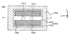
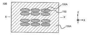
- FIGS. 2 to 4 are diagrams showing a configuration example of the speaker 10A. More specifically, FIG. 2 is a front view of the speaker 10A, and FIG. 3 is a rear view of the speaker 10A.
- FIG. 4 is a cross-sectional view of the speaker 10A in a plane along the XX'line in FIGS. 2 and 3.
- the speaker 10A includes actuators 110-1 and 110-2, elastic members 120-1 and 120-2, in addition to the first flat diaphragm 100A and the second flat diaphragm 130A. And a connecting member 140A (an example of an elastic body) and an edge 150A.
- the second flat diaphragm 130A is composed of the entire flat portion facing the case body 2 when the lid 3 is closed.
- the second flat diaphragm 130A is made of a resin such as polystyrene or a metal such as aluminum.
- the lid 3 is bent at a substantially right angle around the four sides around the second flat diaphragm 130A, and is formed so that the tip of the bent portion at a right angle comes into contact with the case body 2 when the lid 3 is closed. That is, the feature of the musical instrument case 1 of the present embodiment is that the lid 3 is the second flat diaphragm 130A of the speaker 10A.
- the first flat diaphragm 100A is also a member formed in a flat plate shape by a resin such as polystyrene or a metal such as aluminum.
- the first flat diaphragm 100A is formed in a rectangular shape having a smaller area than the second flat diaphragm 130A.
- the first flat diaphragm 100A is provided so as to face the second flat diaphragm 130A.
- the first planar diaphragm 100A is arranged at a position parallel to the second planar diaphragm 130A and at a predetermined distance from the second planar diaphragm 130A in the axial direction of the actuator 110 described later. Has been done.
- a plurality of flat elliptical openings 132 are provided in a portion of the second flat diaphragm 130A facing the first flat diaphragm 100A.
- a total of 12 openings 132, four in the Z direction and three in the X direction, are provided in a matrix on the second plane diaphragm 130A, but the number of openings 132 is 1. The number may be up to 11 or 13 or more.
- the speaker 10A of the present embodiment when the speaker 10A of the present embodiment is viewed from the front side, the first flat diaphragm 100A can be seen through the opening 132.
- the connecting member 140A is composed of a first member 142 and a second member 144.
- the first member 142 and the second member 144 are elastic bodies made of, for example, resin, metal, wood, or the like and having elasticity.
- the first member 142 is a member formed in a hollowed out rectangular parallelepiped shape.
- the inner circumference of the first member 142 is formed to be larger than the outer circumference of the first flat diaphragm 100A.
- the first member 142 is fixed to the second flat diaphragm 130A by using an adhesive or the like so that all the openings 132 fit inside the inner circumference thereof.
- the outer peripheral portion of the first flat diaphragm 100A is connected to the inner peripheral surface of the first member 142 via an edge 150A formed of cloth, paper, urethane, rubber, or the like. Has been done.
- the second member 144 is a strip-shaped member, and is fixed to the first member 142 by using, for example, an adhesive or the like.
- the second member 144 is provided between the two short sides of the first member 142, but may be provided between the two long sides, and is provided so as to connect the diagonals of the first member 142. May be done.
- the second member 144 is adhered to the first member 142 to form the connecting member 140A, but the connecting member 140A is formed by integrally molding the first member 142 and the second member 144. May be good.
- the actuator 110-1 and the actuator 110-2 are provided on the surface of the second member 144 facing the second flat diaphragm 130A.
- the actuators 110-1 and 110-2 are two points on the diagonal line of the first diaphragm 100A.
- Actuators 110-1 and 110-2 may be arranged so as to be connected to each other.
- Each of the actuators 110-1 and 110-2 is formed in a flat columnar shape. In the following, when it is not necessary to distinguish between the actuator 110-1 and the actuator 110-2, it is referred to as "actuator 110".
- first surface one of the two circular surfaces of the actuator 110
- second surface the line connecting the center of the first surface and the center of the second surface of the actuator 110
- axis the line connecting the center of the first surface and the center of the second surface of the actuator 110.
- a first electrode formed in a disk shape, a piezoelectric material, and a second electrode formed in the same disk shape as the first electrode are vertically laminated. It is composed of.
- One of the first electrode and the second electrode is grounded, and a voltage corresponding to the sound signal given to the speaker 10A is applied to the other electrode.
- the piezoelectric material between the first electrode and the second electrode expands and contracts in the axial direction of the actuator 110 according to the voltage applied between the first electrode and the second electrode. That is, the actuator 110 expands and contracts according to a given sound signal.
- One of the first surface and the second surface of the actuator 110-1 is connected to the first flat diaphragm 100A via an elastic member 120-1 formed of, for example, rubber or the like.
- One surface of the actuator 110-2 is also connected to the first flat diaphragm 100A via an elastic member 120-2 formed of, for example, rubber or the like.
- elastic member 120 when it is not necessary to distinguish between the elastic member 120-1 and 120-2, it is referred to as "elastic member 120".
- the actuator 110 expands and contracts in the axial direction in response to the given sound signal, the first plane diaphragm 100A vibrates in the axial direction of the actuator 110, and sound waves corresponding to the sound signal are emitted from both sides of the first plane diaphragm 100A. Be radiated.
- the sound waves radiated from both sides of the first flat diaphragm 100A are radiated to the external space of the lid 3 through the opening 132. That is, the elastic member 120 is arranged between the first flat diaphragm 100A and the actuator 110, and the actuator 110 vibrates the first flat diaphragm 100A via the elastic member 120. Further, the elastic member 120 is directly connected to one surface of the actuator 110.
- the other of the first surface and the second surface of the actuator 110 is fixed to the second member 144 by using, for example, an adhesive or the like. That is, the connecting member 140A is directly connected to the other surface of the actuator 110, and the actuator 110 and the second plane diaphragm 130A are connected to each other. Therefore, the connecting member 140A is subjected to vibration having a phase opposite to that applied to the first plane diaphragm 100A from the actuator 110, and the second plane diaphragm 130A moves in the axial direction of the actuator 110 in response to the vibration. Vibrate. As a result, sound waves corresponding to the sound signal given to the actuator 110 are radiated from the second flat diaphragm 130A toward the external space of the lid 3.
- both the first plane diaphragm 100A and the second plane diaphragm 130A are actuators. It vibrates in the axial direction of 110, that is, in the same direction.
- the sound waves radiated from the first planar diaphragm 100A to the external space and the sound waves radiated from the second planar diaphragm 130A to the external space are in opposite phases and appear to cancel each other out.
- the sound pressure of the sound wave from the first flat diaphragm 100A in a specific frequency band can be adjusted. It is enhanced by the sound wave from the two-plane diaphragm 130A, and the sound pressure in the entire usage band extending from the low range to the high range can be secured. The reason is as follows.
- the first vibration system is formed by the first plane diaphragm 100A, the elastic member 120, and the actuator 110
- the second vibration system is formed by the second plane diaphragm 130A, the connecting member 140A, and the actuator 110.
- the second vibration system is a spring mass system in which the mass of the second flat diaphragm 130A and the elasticity of the connecting member 140A are parameters of the vibration system, and the frequency of the second vibration system can be adjusted by adjusting these parameters. The response can be adjusted.
- the sound pressure of the sound wave from the first flat diaphragm 100A in a specific frequency band is adjusted by adjusting either or both of the mass of the second flat diaphragm 130A and the elasticity of the connecting member 140A. It is possible to arbitrarily realize a uniform characteristic as a sound pressure-frequency characteristic and a characteristic of enhancing a specific band by enhancing by a sound wave from the second flat diaphragm 130A.
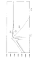
- FIG. 5 is a diagram showing a simulation result for the frequency response of the speaker 10A.
- the graph curve G01 drawn by the dotted line is the graph curve of the frequency response of the first vibration system
- the graph curve G02 drawn by the one-point chain line is the graph curve of the frequency response of the second vibration system.
- the graph curve G03 drawn by the solid line in FIG. 5 is a graph curve of the frequency response of the entire speaker 10A. As shown in FIG. 5, a large dip appears in the vicinity of 80 Hz in the frequency response of the first vibration system.
- the dip is shifted to a frequency lower than 70 Hz by combining the frequency response of the first vibration system and the frequency response of the second vibration system, and the frequency is concerned. It is almost flat in the above frequency bands. Therefore, for example, the lower limit of the used band of the speaker 10A is extended, and it becomes possible to secure the sound pressure in the entire used band extending from the lower range to the high range.
- the speaker 10A according to the present embodiment does not have a bass reflex port and an enclosure. Since it does not have a bass reflex port and an enclosure, the speaker 10A can be made thin, and even if the speaker 10A is provided on the lid 3, the portability and portability of the musical instrument case 1 are not impaired. That is, according to the speaker 10A of the present embodiment, even when a loud bass sound is required, the sound pressure in the entire usage band extending from the low frequency range to the high frequency band is not affected, and the sound pressure is not affected. It becomes possible to secure.
- the effect of the speaker 10A of the present embodiment is not limited to securing the sound pressure in the entire usage band extending from the low range to the high range.
- the performance sound of the musical instrument 4 is detected by a pickup or the like, amplified by an audio amplifier, and radiated by the speaker 10A, the frequency component corresponding to the body resonance of the musical instrument 4 is enhanced by the second vibration system. It is also possible to radiate the faithful performance sound that reproduces the body resonance to the speaker 10A.
- FIGS. 6 to 8 are views showing a configuration example of the speaker 10B. More specifically, FIG. 6 is a front view of the speaker 10B, FIG. 7 is a rear view of the speaker 10B, and FIG. 8 is a cross-sectional view of the speaker 10B in a plane along the XX'line in FIG. is there.
- FIGS. 6 to 8 the same components as those in FIGS. 2 to 4 are designated by the same reference numerals. As is clear from comparing FIGS.
- the speaker 10B has a first flat diaphragm 100A and a second flat diaphragm 130A like the speaker 10A.
- the first flat diaphragm 100A and the second flat diaphragm 130 are arranged to face each other.
- the first planar diaphragm 100A is arranged at a position parallel to the second planar diaphragm 130A and at a predetermined distance from the second planar diaphragm 130A in the axial direction of the actuator 110. ing.
- An actuator 110 and an elastic member 120 are arranged between the first flat diaphragm 100A and the second flat diaphragm 130A. Further, as shown in FIG. 6, the second flat diaphragm 130A of the speaker 10B is also provided with a plurality of openings 132 in a portion facing the first flat diaphragm 100A. As is clear from the comparison between FIGS. 7 and 3 and the comparison between FIGS. 8 and 4, the difference between the configuration of the speaker 10B and the configuration of the speaker 10A is the following three points.
- a connecting member 140B composed of only the first member 142 is provided.
- the actuator 110 and the elastic member 120 are provided in the space between the first flat diaphragm 100A and the second flat diaphragm 130A.
- one of the first surface and the second surface of the actuator 110 is connected to the second plane diaphragm 130A, and the other is directly connected to the first plane diaphragm 100A via the elastic member 120. That is the point.
- a part of the second flat diaphragm 130A also serves as the second member 144 in the speaker 10A.
- the second flat diaphragm 130A and the connecting member 140B may be integrally molded.
- the first vibration system is formed by the first plane diaphragm 100A, the elastic member 120, and the actuator 110
- the second vibration system is formed by the second plane diaphragm 130A and the actuator 110. It is formed. Therefore, the speaker 10B of the present embodiment also has the same effect as the speaker 10A of the first embodiment.
- the first plane diaphragm 100A and the second plane diaphragm 130A are arranged so as to be parallel to each other, both the first plane diaphragm 100A and the second plane diaphragm 130A are arranged. It vibrates in the axial direction of the actuator 110, that is, in the same direction.
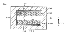
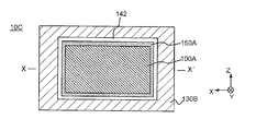
- FIGS. 9 to 11 are views showing a configuration example of the speaker 10C according to the third embodiment of the present invention. More specifically, FIG. 9 is a front view of the speaker 10C, FIG. 10 is a rear view of the speaker 10C, and FIG. 11 is a cross-sectional view of the speaker 10C in a plane along the XX'line in FIG.
- FIGS. 9 to 11 the same components as those in FIGS. 2 to 4 are designated by the same reference numerals.
- FIGS. 9 and 2 the comparison between FIGS. 10 and 3 and the comparison between FIGS. 11 and 4
- the difference between the configuration of the speaker 10C and the configuration of the speaker 10A is the following three points. is there.
- a second flat diaphragm 130B is provided in place of the second flat diaphragm 130A.
- the second flat diaphragm 130B has only one rectangular opening 134 corresponding to the portion surrounded by the inner circumference of the first member 142 instead of the plurality of openings 132, which is the same as that of the second flat diaphragm 130A. different.
- the second point is that the connecting member 140A is provided with respect to the second flat diaphragm 130B so that the second member 144 of the connecting member 140A is located on the same plane as the second flat diaphragm 130B.
- the elastic member 150A and the first plane diaphragm 100A are provided on the side of the first member 142 opposite to the side in contact with the second plane diaphragm 130B. is there. Also in the third embodiment, the first plane diaphragm 100A is arranged at a position parallel to the second plane diaphragm 130B and separated from the second parallel diaphragm 130B by a predetermined distance. An actuator 110 and an elastic member 120 are arranged between the first flat diaphragm 100A and the second flat diaphragm 130B.
- the first vibration system is formed by the first plane diaphragm 100A, the elastic member 120, and the actuator 110, and the second plane diaphragm 130B, the connecting member 140A, and the actuator 110 form the second vibration system. Vibration system is formed. Therefore, the same effect as that of the speaker 10A of the first embodiment can be obtained by the speaker 10C of the present embodiment. Also in this embodiment, since the first plane diaphragm 100A and the second plane diaphragm 130B are arranged so as to be parallel to each other, both the first plane diaphragm 100A and the second plane diaphragm 130B are arranged. It vibrates in the axial direction of the actuator 110, that is, in the same direction.
- the area of the first flat diaphragm 100A is smaller than the area of the second flat diaphragm 130A, but the area of the first flat diaphragm 100A is the second. It may be configured equal to the area of the flat diaphragm 130A.
- the number of actuators 110 in the speakers 10A, 10B and 10C of each of the above embodiments was two, it may be one or three or more.
- the actuator 110 of the first embodiment is connected to the first plane vibrating body 100A via the elastic member 120, the actuator 110 may be directly connected to the first plane vibrating body 100A.
- the actuator 110 in each of the above embodiments may be of the electrokinetic type.
- the electrokinetic actuator has a base portion including a magnetic circuit and the like, and a vibrating portion connected to the base portion via a damper.
- the vibrating portion is arranged so as to be vibrable in the axial direction with respect to the base portion.
- the base portion may be fixed to the second plane diaphragm and the vibrating portion may be fixed to the first plane diaphragm.
- the damper functions as an elastic member.
- the present invention may be applied to a speaker mounted on a portable information terminal such as a smartphone, a tablet terminal, a portable game, or a notebook computer. Even for speakers mounted on portable information terminals, the sound pressure over the entire usage band from low to high frequencies is not affected even when high-volume output is required, without affecting portability or portability. This is because it is still preferable that it can be secured.
- the present invention may be applied to a PA speaker used in an event such as a concert.
- the PA speaker is also preferably highly portable even when a large volume output is required, and it is preferable that the sound pressure can be secured in the entire usage band extending from the low range to the high range. is there.
- the first plane diaphragm, the actuator connected to the first plane diaphragm and applying vibration corresponding to the sound signal to the first plane diaphragm, the second plane diaphragm, the actuator and the first Any aspect may be used as long as it provides an elastic body for connecting the two-plane diaphragm and a speaker characterized by having.
- FIGS. 12 to 14 are diagrams showing a configuration example of the speaker 10D, which is an application example of the present invention to a PA speaker.
- FIG. 12 is a front view of the speaker 10D
- FIG. 13 is a rear view of the speaker 10D
- 14 is a cross-sectional view of the speaker 10D in a plane along the XX'line in FIGS. 12 and 13.
- the speaker 10D includes a front plate 160, edges 150B-1 and 150B-2, a connecting member 140C, a second flat diaphragm 130C, an elastic member 120, and an actuator 110.
- the first flat diaphragm 100B is provided.
- the front plate 160 is provided with a circular opening 162, and the edge 150B-1 formed in an annular shape is provided along the inner circumference of the opening 162.
- the outer circumference of the second plane diaphragm 130C formed in an annular shape is connected to the inner circumference of the edge 150B-1, and the edge 150B- formed in an annular shape is connected to the inner circumference of the second plane diaphragm 130C.
- the outer circumference of 2 is connected.
- the outer circumference of the first flat diaphragm 100B formed in a disk shape is connected to the inner circumference of the edge 150B-2. As shown in FIG.
- the first plane diaphragm 100B and the second plane diaphragm 130C are arranged on the same plane.
- the first flat diaphragm 100B is arranged at a position separated from the second flat diaphragm 130C by a predetermined distance in a direction parallel to the first flat diaphragm 100B.
- an edge 150B-2 is arranged between the first flat diaphragm 100A and the second flat diaphragm 130A.
- the connecting member 140C is composed of a first member 146 formed in a cross shape and four second members 148 each formed in a rectangular parallelepiped shape. Each of the four second members 148 is provided at each of the four ends of the first member 146 so that the center of the first member 146 and the center of the first flat diaphragm 100B overlap each other. It is fixed to the two-plane diaphragm 130C.
- One of the first surface and the second surface of the actuator 110 is connected to the surface of the first member 146 facing the first plane diaphragm 100B, and the other surface of the actuator 110 is an elastic member 120. It is connected to the first flat diaphragm 100B via.
- the shape of the first member 146 is not limited to the cross shape, and may be a three-pronged shape or a six-pronged shape.
- a second member 148 may be provided at each of the three ends of the first member 146 to form the connecting member 146C.
- one second member 148 may be provided at each of the six ends of the first member 146 to form the connecting member 146C.
- a first vibration system is formed by the first plane diaphragm 100B, the elastic member 120, and the actuator 110, and the second plane diaphragm 130C, the connecting member 140C, and the actuator 110 form a first vibration system.
- a second vibration system is formed. Therefore, the same effect as the speaker of each of the above-described embodiments can be obtained by the speaker 10D of the present modification.
- both the first flat diaphragm 100B and the second flat diaphragm 130C are actuators 110. Vibrates in the axial direction of, that is, in the same direction.
Landscapes
- Engineering & Computer Science (AREA)
- Physics & Mathematics (AREA)
- Acoustics & Sound (AREA)
- Multimedia (AREA)
- Signal Processing (AREA)
- Electrophonic Musical Instruments (AREA)
- Piezo-Electric Transducers For Audible Bands (AREA)
- Diaphragms For Electromechanical Transducers (AREA)
- Obtaining Desirable Characteristics In Audible-Bandwidth Transducers (AREA)
- Auxiliary Devices For Music (AREA)
Abstract
大音量の出力を必要とされる場合でも運搬性や携帯性に影響を与えることなく、低域から高域に亙る使用帯域全体での音圧の確保が可能なスピーカを提供する。 第1平面振動板100Aと、第1平面振動板100Aに接続され、音信号に応じた振動を第1平面振動板100Aに与えるアクチュエータ110-1および110-2と、第2平面振動板130Aと、アクチュエータ110-1および110-2と第2平面振動板130Aとに接続され、第1平面振動板100Aに与えられる振動とは逆相の振動をアクチュエータ110-1および110-2から与えられる連結部材140と、を有するスピーカ10A、を提供する。
Description
本発明は、スピーカ、および楽器ケースに関する。
スピーカの一例として、平面振動板をアクチュエータで加振するアクチュエータ駆動型スピーカと、円錐状の振動板を有するダイナミック型スピーカとが挙げられる。アクチュエータ駆動型スピーカの場合、振動板は高剛性、高重量体であることが多く、特に低音域での音圧の確保が難しい等、低域から高域に亙る使用帯域全体での音圧の確保が難しいといった問題がある。一方、ダイナミック型スピーカでは、大音量を出力するにはスピーカユニットの大口径化が必要となり、スピーカの厚みが大きくなる。このため、ダイナミック型スピーカは運搬性や携帯性を求められる製品には適さない、といった問題がある。低音域の増強を行うスピーカの一例としては、位相反転型エンクロージャを用いたバスレフ型スピーカが挙げられる(例えば、特許文献1参照)。
バスレフ型スピーカでは、バスレフポートおよびエンクロージャが必要となるため、大出力が必要で、かつ運搬性や携帯性を求められる製品には適さない。
本発明は、上記課題に鑑みて為されたものであり、大音量の出力を必要とされる場合でも運搬性や携帯性に影響を与えることなく、低域から高域に亙る使用帯域全体での音圧の確保が可能なスピーカを提供することを目的とする。
上記課題を解決するために本発明は、第1平面振動板と、音信号に応じた振動を前記第1平面振動板に与えるアクチュエータと、前記第1平面振動板から離間し、前記アクチュエータによって振動させられる第2平面振動板と、を有することを特徴とするスピーカ、を提供する。
より好ましい態様のスピーカにおいては、前記第1平面振動板の面積は前記第2平面振動板の面積よりも小さいことを特徴とする。
より好ましい態様のスピーカにおいては、前記アクチュエータと前記第2平面振動板とを接続する弾性体を、さらに備えることを特徴とする。
より好ましい態様のスピーカにおいては、前記アクチュエータと前記第2平面振動板とを接続する弾性体を、さらに備えることを特徴とする。
より好ましい態様のスピーカにおいては、前記弾性体と前記第2平面振動板とが一体成型されていることを特徴とする。
より好ましい態様のスピーカにおいては、前記第1平面振動板と前記第2平面振動板とが対向して配置されていることを特徴とする。
より好ましい態様のスピーカにおいては、前記第1平面振動板と前記第2平面振動板は、互いに平行に配置されていることを特徴とする。
より好ましい態様のスピーカにおいては、前記第1平面振動板と前記第2平面振動板は、互いに平行に配置されていることを特徴とする。
より好ましい態様のスピーカにおいては、前記第1平面振動板と前記第2平面振動板とが同一平面上に配置されていることを特徴とする。
より好ましい態様のスピーカにおいては、前記第1平面振動板と前記アクチュエータの間に配置された弾性部材をさらに備え、前記アクチュエータは、前記弾性部材を介して前記第1平面振動板に前記振動を与えることを特徴とする。
より好ましい態様のスピーカにおいては、前記第2平面振動板には、前記第1平面振動板が前記アクチュエータから付与される振動の逆相の振動が、前記アクチュエータより付与されることを特徴とする。
より好ましい態様のスピーカにおいては、前記アクチュエータは、第1面及び第2面を有する形状であり、前記第1平面振動板は、前記アクチュエータの前記第1面に接続され、前記第2平面振動板は、前記アクチュエータの前記第2面に接続されることを特徴とする。
より好ましい態様のスピーカにおいては、前記弾性部材は、前記アクチュエータの前記第1面に直接接続されることを特徴とする。
より好ましい態様のスピーカにおいては、前記弾性体は、前記アクチュエータの前記第2面に直接接続されることを特徴とする。
より好ましい態様のスピーカにおいては、前記アクチュエータの前記第2面は、前記第2平面振動板に直接接続されることを特徴とする。
より好ましい態様のスピーカにおいては、前記第1平面振動板と前記アクチュエータの間に配置された弾性部材をさらに備え、前記アクチュエータは、前記弾性部材を介して前記第1平面振動板に前記振動を与えることを特徴とする。
より好ましい態様のスピーカにおいては、前記第2平面振動板には、前記第1平面振動板が前記アクチュエータから付与される振動の逆相の振動が、前記アクチュエータより付与されることを特徴とする。
より好ましい態様のスピーカにおいては、前記アクチュエータは、第1面及び第2面を有する形状であり、前記第1平面振動板は、前記アクチュエータの前記第1面に接続され、前記第2平面振動板は、前記アクチュエータの前記第2面に接続されることを特徴とする。
より好ましい態様のスピーカにおいては、前記弾性部材は、前記アクチュエータの前記第1面に直接接続されることを特徴とする。
より好ましい態様のスピーカにおいては、前記弾性体は、前記アクチュエータの前記第2面に直接接続されることを特徴とする。
より好ましい態様のスピーカにおいては、前記アクチュエータの前記第2面は、前記第2平面振動板に直接接続されることを特徴とする。
また、上記課題を解決するために本発明は、楽器を収納するケース本体と、蓋体と、上記各態様の何れかのスピーカと、を有し、前記蓋体を前記第2平面振動板としたことを特徴とする楽器ケース、を提供する。
以下、図面を参照しつつ本発明の実施形態を説明する。(A:第1実施形態)
図1は、本発明の一実施形態による楽器ケース1の構成例を示す図である。図1に示す楽器ケース1は、例えばギター等の楽器4を収納するための楽器ケースである。図1に示すように楽器ケース1は、楽器を収納するケース本体2と、ケース本体2に対して開閉自在に設けられた蓋体3と、蓋体3に設けられたスピーカ10Aとを有する。本実施形態の楽器ケース1の特徴は、第1平面振動板100Aと第2平面振動板130Aとを有するスピーカ10Aを蓋体3に設けた点にある。以下、スピーカ10Aを中心に説明する。
図1は、本発明の一実施形態による楽器ケース1の構成例を示す図である。図1に示す楽器ケース1は、例えばギター等の楽器4を収納するための楽器ケースである。図1に示すように楽器ケース1は、楽器を収納するケース本体2と、ケース本体2に対して開閉自在に設けられた蓋体3と、蓋体3に設けられたスピーカ10Aとを有する。本実施形態の楽器ケース1の特徴は、第1平面振動板100Aと第2平面振動板130Aとを有するスピーカ10Aを蓋体3に設けた点にある。以下、スピーカ10Aを中心に説明する。
図2~図4は、スピーカ10Aの構成例を示す図である。より詳細に説明すると、図2はスピーカ10Aの正面図であり、図3はスピーカ10Aの背面図である。そして、図4は、図2および図3におけるXX´線に沿った平面によるスピーカ10Aの断面図である。図2~図4に示すように、スピーカ10Aは、第1平面振動板100Aおよび第2平面振動板130Aの他に、アクチュエータ110-1および110-2と、弾性部材120-1および120-2と、連結部材140A(弾性体の一例)と、エッジ150Aとを有する。
第2平面振動板130Aは、蓋体3が閉じられたときにケース本体2に対向する平面部全体からなる。第2平面振動板130Aは、ポリスチレン等の樹脂、またはアルミニウム等の金属により形成されている。蓋体3は第2平面振動板130Aの周囲4辺で略直角に曲げられ、蓋体3を閉じたときに直角に曲がった部分の先端がケース本体2と接するように形成されている。つまり、本実施形態の楽器ケース1の特徴は、蓋体3をスピーカ10Aの第2平面振動板130Aとした点にある。第1平面振動板100Aも、ポリスチレン等の樹脂、またはアルミニウム等の金属により平らな板状に形成された部材である。第1平面振動板100Aは、第2平面振動板130Aよりも面積の小さい矩形状に形成されている。本実施形態のスピーカ10Aでは、第1平面振動板100Aは、第2平面振動板130Aと対向するように設けられる。図4に示すように、第1平面振動板100Aは、第2平面振動板130Aと平行で、且つ、後述のアクチュエータ110の軸方向において、第2平面振動板130Aから所定距離離間した位置に配置されている。第2平面振動板130Aにおいて第1平面振動板100Aと対向する部分には、扁平な楕円形状の開口132が複数設けられている。図2に示す例では、Z方向に4個ずつ、X方向に3個ずつの合計12個の開口132が第2平面振動板130Aにマトリクス状に設けられているが、開口132の数は1~11個であっても良いし、13個以上であってもよい。図2に示すように、本実施形態のスピーカ10Aを正面側から見ると、第1平面振動板100Aが開口132越しに見える。
図3および図4に示すように、連結部材140Aは、第1部材142と、第2部材144とにより構成されている。第1部材142及び第2部材144は、例えば樹脂、金属または木材等で構成され、弾性を有する弾性体である。第1部材142は、くり抜かれた直方体状に形成された部材である。第1部材142は、内周が第1平面振動板100Aの外周よりも大きい形状に形成されている。第1部材142は、その内周の内側に全ての開口132が収まるように、接着剤等を用いて第2平面振動板130Aに固定されている。図3及び図4に示すように、第1部材142の内周面には、布、紙、ウレタンまたはゴム等で形成されたエッジ150Aを介して、第1平面振動板100Aの外周部分が接続されている。
図3及び図4に示すように、第2部材144は、帯状部材であり、例えば接着剤等を用いて第1部材142に固定されている。本実施形態では、第2部材144は、第1部材142における2つの短辺間に設けられるが、2つの長辺間に設けられてもよく、第1部材142の対角を結ぶように設けられてもよい。また、本実施形態では第1部材142に第2部材144を接着して連結部材140Aが構成されるが、連結部材140Aは、第1部材142と第2部材144との一体成型により構成されてもよい。
図4に示すように、第2部材144において第2平面振動板130Aと対向する面には、アクチュエータ110-1とアクチュエータ110-2とが設けられている。なお、第1部材142の対角を結ぶように第2部材144を設けて連結部材140Aを構成する場合には、アクチュエータ110-1および110-2が第1振動板100Aの対角線上の2点にそれぞれ接続されるように、アクチュエータ110-1および110-2が配置されればよい。アクチュエータ110-1および110-2の各々は、扁平な円柱状に形成されている。以下では、アクチュエータ110-1とアクチュエータ110-2とを区別する必要がない場合には、「アクチュエータ110」と表記する。また、以下では、アクチュエータ110において円形に形成された2つの面のうちの一方を「第1面」と呼び、他方を「第2面」と呼ぶ。また、以下では、アクチュエータ110の第1面の中心と第2面の中心とを結ぶ線をアクチュエータ110の「軸」と呼ぶ。
図4では詳細な図示を省略したが、アクチュエータ110は、円盤状に形成された第1電極と、圧電材料と、第1電極と同じ円盤状に形成された第2電極とを軸方向に積層して構成されている。第1電極および第2電極の一方は接地されており、他方にはスピーカ10Aに与えられる音信号に応じた電圧が印加される。第1電極および第2電極間の圧電材料は、第1電極および第2電極間に与えられる電圧に応じてアクチュエータ110の軸方向に伸縮する。つまり、アクチュエータ110は、与えられる音信号に応じて伸縮する。
アクチュエータ110-1の第1面および第2面のうちの一方の面は、例えばゴム等で形成された弾性部材120-1を介して第1平面振動板100Aに接続されている。アクチュエータ110-2における一方の面も、例えばゴム等で形成された弾性部材120-2を介して第1平面振動板100Aに接続されている。以下では、弾性部材120-1と120-2とを区別する必要がない場合には「弾性部材120」と表記する。与えられた音信号に応じてアクチュエータ110が軸方向に伸縮すると、第1平面振動板100Aはアクチュエータ110の軸方向に振動し、上記音信号に応じた音波が第1平面振動板100Aの両面から放射される。第1平面振動板100Aの両面から放射される音波のうち、第2平面振動板130A側の面から放射される音波は、開口132を通って蓋体3の外部空間へ放射される。つまり、弾性部材120は、第1平面振動板100Aとアクチュエータ110の間に配置され、アクチュエータ110は、弾性部材120を介して、第1平面振動板100Aに振動を与えている。また、弾性部材120は、アクチュエータ110の一方の面に直接接続されている。
アクチュエータ110の第1面および第2面のうちの他方は、例えば接着剤等を用いて第2部材144に固定されている。つまり、連結部材140Aは、アクチュエータ110の他方の面に直接接続し、アクチュエータ110と第2平面振動板130Aを接続している。このため、連結部材140Aには、第1平面振動板100Aに与えられる振動とは逆相の振動がアクチュエータ110から与えられ、当該振動に応じて第2平面振動板130Aがアクチュエータ110の軸方向に振動する。これにより、第2平面振動板130Aからも蓋体3の外部空間へ向けて、アクチュエータ110に与えられた音信号に応じた音波が放射される。なお、上述のように、第1平面振動板100Aと第2平面振動板130Aは、互いに平行になるように配置されるため、第1平面振動板100A及び第2平面振動板130Aは、共にアクチュエータ110の軸方向、つまり同じ方向に振動する。
スピーカ10Aでは、第1平面振動板100Aから外部空間へ放射される音波と第2平面振動板130Aから外部空間へ放射される音波とが互いに逆相になり、打消し合うかのように見える。しかし、スピーカ10Aでは、第2平面振動板130Aの質量と連結部材140Aの弾性の何れか一方または両方を調整することで、第1平面振動板100Aからの音波の特定周波数帯域の音圧を第2平面振動板130Aからの音波により増強し、低域から高域に亙る使用帯域全体での音圧を確保することができる。その理由は次の通りである。
スピーカ10Aでは、第1平面振動板100Aと弾性部材120とアクチュエータ110とで第1の振動系が形成され、第2平面振動板130Aと連結部材140Aとアクチュエータ110とで第2の振動系が形成される。第2の振動系は、第2平面振動板130Aの質量と、連結部材140Aの弾性とを振動系のパラメータとするバネマス系であり、これらパラメータを調整することで当該第2の振動系の周波数応答を調整することができる。このため、スピーカ10Aでは、第2平面振動板130Aの質量と連結部材140Aの弾性の何れか一方または両方を調整することで、第1平面振動板100Aからの音波の特定周波数帯域の音圧を第2平面振動板130Aからの音波により増強し、音圧-周波数特性として均一な特性や特定帯域を増強する特性を任意に実現可能になる。
図5は、スピーカ10Aの周波数応答についてのシミュレーション結果を示す図である。図5において点線で描画されたグラフ曲線G01は第1の振動系の周波数応答のグラフ曲線であり、一点鎖線で描画されたグラフ曲線G02は第2の振動系の周波数応答のグラフ曲線である。そして、図5において実線で描画されたグラフ曲線G03はスピーカ10A全体の周波数応答のグラフ曲線である。図5に示すように、第1の振動系の周波数応答には、80Hz付近に大きなディップが現れている。これに対して、スピーカ10A全体の周波数応答では、第1の振動系の周波数応答と第2の振動系の周波数応答との合成により、上記ディップは70Hzよりも下の周波数にシフトし、当該周波数以上の周波数帯域では略平坦になっている。このため、例えばスピーカ10Aの使用帯域の下限が拡張されており、より低域から、高域に亙る使用帯域全体での音圧の確保が可能になる。
ここで注目すべき点は、本実施形態によるスピーカ10Aは、バスレフポートおよびエンクロージャを有しないという点である。バスレフポートおよびエンクロージャを有しないので、スピーカ10Aを薄型にすることが可能であり、スピーカ10Aを蓋体3に設けても、楽器ケース1の運搬性や携帯性が損なわれることはない。つまり、本実施形態のスピーカ10Aによれば、大音量の低音を必要とされる場合でも運搬性や携帯性に影響を与えることなく、低域から高域に亙る使用帯域全体での音圧の確保が可能になる。
なお、本実施形態のスピーカ10Aによる効果は、低域から高域に亙る使用帯域全体での音圧の確保に限定される訳ではない。例えば、楽器4の演奏音をピックアップ等で検出し、オーディオアンプにより増幅してスピーカ10Aで放射する場合には、第2の振動系により楽器4の胴共鳴に応じた周波数成分を増強することで、胴共鳴を再現した忠実な演奏音をスピーカ10Aに放射させることも可能になる。
(B:第2実施形態)
次いで、本発明の第2実施形態によるスピーカ10Bについて説明する。スピーカ10Bもスピーカ10Aと同様に楽器ケース1の蓋体3に設けられるスピーカである。図6から図8は、スピーカ10Bの構成例を示す図である。より詳細に説明すると、図6はスピーカ10Bの正面図であり、図7は、スピーカ10Bの背面図であり、図8は、図7におけるXX´線に沿った平面によるスピーカ10Bの断面図である。図6から図8では、図2から図4におけるものと同じ構成要素には同じ符号が付されている。図6と図2とを対比すれば明らかなように、スピーカ10Bはスピーカ10Aと同様に第1平面振動板100Aと第2平面振動板130Aとを有する。図8に示すように、本実施形態のスピーカ10Bにおいても第1実施形態におけるスピーカ10Aと同様に、第1平面振動板100Aと第2平面振動板130とが対向して配置されている。なお、第2実施形態においても、第1平面振動板100Aは、第2平面振動板130Aと平行で、且つアクチュエータ110の軸方向において、第2平面振動板130Aから所定距離離間した位置に配置されている。第1平面振動板100Aと第2平面振動板130Aの間には、アクチュエータ110と弾性部材120が配置されている。また、図6に示すように、スピーカ10Bの第2平面振動板130Aにも、第1平面振動板100Aと対向する部分に複数の開口132が設けられている。図7と図3の対比、および図8と図4の対比から明らかなように、スピーカ10Bの構成とスピーカ10Aの構成の相違点は、以下の3つの点である。
次いで、本発明の第2実施形態によるスピーカ10Bについて説明する。スピーカ10Bもスピーカ10Aと同様に楽器ケース1の蓋体3に設けられるスピーカである。図6から図8は、スピーカ10Bの構成例を示す図である。より詳細に説明すると、図6はスピーカ10Bの正面図であり、図7は、スピーカ10Bの背面図であり、図8は、図7におけるXX´線に沿った平面によるスピーカ10Bの断面図である。図6から図8では、図2から図4におけるものと同じ構成要素には同じ符号が付されている。図6と図2とを対比すれば明らかなように、スピーカ10Bはスピーカ10Aと同様に第1平面振動板100Aと第2平面振動板130Aとを有する。図8に示すように、本実施形態のスピーカ10Bにおいても第1実施形態におけるスピーカ10Aと同様に、第1平面振動板100Aと第2平面振動板130とが対向して配置されている。なお、第2実施形態においても、第1平面振動板100Aは、第2平面振動板130Aと平行で、且つアクチュエータ110の軸方向において、第2平面振動板130Aから所定距離離間した位置に配置されている。第1平面振動板100Aと第2平面振動板130Aの間には、アクチュエータ110と弾性部材120が配置されている。また、図6に示すように、スピーカ10Bの第2平面振動板130Aにも、第1平面振動板100Aと対向する部分に複数の開口132が設けられている。図7と図3の対比、および図8と図4の対比から明らかなように、スピーカ10Bの構成とスピーカ10Aの構成の相違点は、以下の3つの点である。
第1に、連結部材140Aに代えて、第1部材142のみで構成された連結部材140Bを設けた点である。第2に、第1平面振動板100Aと第2平面振動板130Aとの間の空間にアクチュエータ110と弾性部材120とが設けられる点である。そして、第3に、アクチュエータ110の第1面および第2面のうちの一方が第2平面振動板130Aに接続され、他方が弾性部材120を介して第1平面振動板100Aに直接接続されている点である。本実施形態のスピーカ10Bでは、第2平面振動板130Aの一部がスピーカ10Aにおける第2部材144の役割を兼ねる。本実施形態のスピーカ10Bでは、第2平面振動板130Aと連結部材140Bとが一体成型されていてもよい。
本実施形態のスピーカ10Bにおいても、第1平面振動板100Aと弾性部材120とアクチュエータ110とによって第1の振動系が形成され、第2平面振動板130Aとアクチュエータ110とによって第2の振動系が形成される。このため、本実施形態のスピーカ10Bによっても、第1実施形態のスピーカ10Aと同じ効果が得られる。なお、本実施形態においても、第1平面振動板100Aと第2平面振動板130Aは、互いに平行になるように配置されるため、第1平面振動板100A及び第2平面振動板130Aは、共にアクチュエータ110の軸方向、つまり同じ方向に振動する。
(C:第3実施形態)
次いで、本発明の第3実施形態によるスピーカ10Cについて説明する。スピーカ10Cもスピーカ10Aと同様に楽器ケース1の蓋体3に設けられるスピーカである。図9から図11は、本発明の第3実施形態によるスピーカ10Cの構成例を示す図である。より詳細に説明すると、図9はスピーカ10Cの正面図であり、図10はスピーカ10Cの背面図であり、図11は図9におけるXX´線に沿った平面によるスピーカ10Cの断面図である。図9から図11では、図2から図4におけるものと同じ構成要素には同じ符号が付されている。図9と図2の対比、図10と図3の対比、および図11と図4の対比から明らかなように、スピーカ10Cの構成とスピーカ10Aの構成の相違点は、以下の3つの点である。
次いで、本発明の第3実施形態によるスピーカ10Cについて説明する。スピーカ10Cもスピーカ10Aと同様に楽器ケース1の蓋体3に設けられるスピーカである。図9から図11は、本発明の第3実施形態によるスピーカ10Cの構成例を示す図である。より詳細に説明すると、図9はスピーカ10Cの正面図であり、図10はスピーカ10Cの背面図であり、図11は図9におけるXX´線に沿った平面によるスピーカ10Cの断面図である。図9から図11では、図2から図4におけるものと同じ構成要素には同じ符号が付されている。図9と図2の対比、図10と図3の対比、および図11と図4の対比から明らかなように、スピーカ10Cの構成とスピーカ10Aの構成の相違点は、以下の3つの点である。
第1に、第2平面振動板130Aに代えて第2平面振動板130Bを設けた点である。第2平面振動板130Bは、複数の開口132に代えて、第1部材142の内周で囲まれた部分に対応する矩形状の開口134を1つだけ有する点が第2平面振動板130Aと異なる。第2に、連結部材140Aの第2部材144が第2平面振動板130Bと同一平面上に位置するように、第2平面振動板130Bに対して連結部材140Aが設けられている点である。そして、第3に、図11に示したように、第1部材142において第2平面振動板130Bに接する側とは反対側に弾性部材150Aおよび第1平面振動板100Aが設けられている点である。なお、第3実施形態においても、第1平面振動板100Aは、第2平面振動板130Bと平行で、且つ第2平行振動板130Bから所定距離離間した位置に配置されている。第1平面振動板100Aと第2平面振動板130Bの間には、アクチュエータ110と弾性部材120が配置されている。
本実施形態のスピーカ10Cにおいても、第1平面振動板100Aと弾性部材120とアクチュエータ110とによって第1の振動系が形成され、第2平面振動板130Bと連結部材140Aとアクチュエータ110とによって第2の振動系が形成される。このため、本実施形態のスピーカ10Cによっても、第1実施形態のスピーカ10Aと同じ効果が得られる。なお、本実施形態においても、第1平面振動板100Aと第2平面振動板130Bは、互いに平行になるように配置されるため、第1平面振動板100A及び第2平面振動板130Bは、共にアクチュエータ110の軸方向、つまり同じ方向に振動する。
(B:変形)
以上本発明の各実施形態について説明したが、上記各実施形態に以下の変形を加えても勿論良い。(1)上記第1実施形態のスピーカ10Aでは、第1平面振動板100Aの面積が第2平面振動板130Aの面積よりも小さく構成されていたが、第1平面振動板100Aの面積が第2平面振動板130Aの面積と等しく構成されていてもよい。また、上記各実施形態のスピーカ10A、10Bおよび10Cにおけるアクチュエータ110の数は2個であったが、1個であってもよく、また3個以上であってもよい。また、第1実施形態のアクチュエータ110は、第1平面振動体100Aに弾性部材120を介して接続されていたが、アクチュエータ110を第1平面振動体100Aに直接接続しても良い。
以上本発明の各実施形態について説明したが、上記各実施形態に以下の変形を加えても勿論良い。(1)上記第1実施形態のスピーカ10Aでは、第1平面振動板100Aの面積が第2平面振動板130Aの面積よりも小さく構成されていたが、第1平面振動板100Aの面積が第2平面振動板130Aの面積と等しく構成されていてもよい。また、上記各実施形態のスピーカ10A、10Bおよび10Cにおけるアクチュエータ110の数は2個であったが、1個であってもよく、また3個以上であってもよい。また、第1実施形態のアクチュエータ110は、第1平面振動体100Aに弾性部材120を介して接続されていたが、アクチュエータ110を第1平面振動体100Aに直接接続しても良い。
(2)上記各実施形態におけるアクチュエータ110は動電型であってもよい。動電型アクチュエータは、磁気回路等を含むベース部と、ダンパを介してベース部に接続される振動部とを有する。振動部はベース部に対して軸方向に振動可能に配置される。動電型アクチュエータを用いて本発明のスピーカを構成する場合、ベース部が第2平面振動板に固定され、振動部が第1平面振動板に固定されればよい。この場合、ダンパが弾性部材として機能する。
(3)上記各実施形態では、楽器ケース1に設けられるスピーカへの本発明の適用例を説明した。しかし、スマートフォンやタブレット端末、携帯型ゲーム、ノート型パソコンなどの携帯型情報端末に搭載されるスピーカに本発明を適用してもよい。携帯型情報端末に搭載されるスピーカについても、大音量の出力を必要とされる場合でも運搬性や携帯性に影響を与えることなく、低域から高域に亙る使用帯域全体での音圧の確保が可能であることが好ましいことには変わりはないからである。
また、コンサートなどのイベントにて使用されるPA用スピーカに本発明を適用してもよい。PA用スピーカについても、大音量の出力を必要とされる場合でも運搬性が高いことが好ましく、低域から高域に亙る使用帯域全体での音圧の確保が可能であることが好ましいからである。要は、第1平面振動板と、前記第1平面振動板に接続され、音信号に応じた振動を前記第1平面振動板に与えるアクチュエータと、第2平面振動板と、前記アクチュエータと前記第2平面振動板とを接続する弾性体と、を有することを特徴とするスピーカ、を提供する態様であればよい。
図12から図14は、PA用スピーカへの本発明の適用例であるスピーカ10Dの構成例を示す図である。図12はスピーカ10Dの正面図であり、図13はスピーカ10Dの背面図である。そして、図14は、図12および図13におけるXX´線に沿った平面によるスピーカ10Dの断面図である。図12から図14に示すように、スピーカ10Dは、正面板160と、エッジ150B-1および150B-2と、連結部材140Cと、第2平面振動板130Cと、弾性部材120と、アクチュエータ110と、第1平面振動板100Bとを有する。
図12から図14に示すように、正面板160には円形の開口162が設けられており、円環状に形成されたエッジ150B-1が当該開口162の内周に沿って設けられている。エッジ150B-1の内周には円環状に形成された第2平面振動板130Cの外周が接続されており、第2平面振動板130Cの内周には、円環状に形成されたエッジ150B-2の外周が接続されている。そして、エッジ150B-2の内周には円盤状に形成された第1平面振動板100Bの外周が接続されている。図14に示すように、スピーカ10Dでは、第1平面振動板100Bと第2平面振動板130Cとは同一平面上に配置されている。なお、本構成例においては、第1平面振動板100Bは、第1平面振動板100Bに平行な方向において、第2平面振動板130Cから所定距離離間した位置に配置されている。また、第1平面振動板100Aと第2平面振動板130Aの間には、エッジ150B-2が配置されている。
連結部材140Cは十字型に構成された第1部材146と、各々直方体状に形成された4つの第2部材148とにより構成されている。4つの第2部材148の各々は、第1部材146の4つの端部にそれぞれ1個ずつ設けられており、第1部材146の中心と第1平面振動板100Bの中心とが重なるように第2平面振動板130Cに固定されている。第1部材146において第1平面振動板100Bと対向する面にはアクチュエータ110の第1面および第2面のうちの一方の面が接続されており、アクチュエータ110の他方の面は弾性部材120を介して第1平面振動板100Bに接続されている。なお、第1部材146の形状は十字型には限定されず、三又形状または六又形状であってもよい。第1部材146として三又形状の部材を用いる場合には、第1部材146の3つの端部にそれぞれ1個ずつ第2部材148を設けて連結部材146Cを構成すればよい。また、第1部材146として六又形状の部材を用いる場合には、第1部材146の6つの端部にそれぞれ1個ずつ第2部材148を設けて連結部材146Cを構成すればよい。
図12から図14に示すスピーカ10Dでは、第1平面振動板100Bと弾性部材120とアクチュエータ110とにより第1の振動系が形成され、第2平面振動板130Cと連結部材140Cとアクチュエータ110とにより第2の振動系が形成される。したがって、本変形例のスピーカ10Dによっても、上記各実施形態のスピーカと同じ効果が得られる。なお、本構成例においては、第1平面振動板100Bと第2平面振動板130Cは、同一平面上に配置されるため、第1平面振動板100B及び第2平面振動板130Cは、共にアクチュエータ110の軸方向、つまり同じ方向に振動する。
1…楽器ケース、2…ケース本体、3…蓋体、4…楽器、10A、10B、10C、10D…スピーカ、100A、100B…第1平面振動板、110,110-1,110-2…アクチュエータ、120,120-1,120-2…弾性部材、130A,130B、130C…第2平面振動板、140A、140B、140C…連結部材。
Claims (14)
- 第1平面振動板と、
音信号に応じた振動を前記第1平面振動板に与えるアクチュエータと、
前記第1平面振動板から離間し、前記アクチュエータによって振動させられる第2平面振動板と、
を有するスピーカ。 - 前記第1平面振動板の面積は、前記第2平面振動板の面積よりも小さい請求項1に記載のスピーカ。
- 前記アクチュエータと前記第2平面振動板とを接続する弾性体を、さらに備える請求項1または2に記載のスピーカ。
- 前記弾性体と前記第2平面振動板とが一体成型されている請求項3に記載のスピーカ。
- 前記第1平面振動板と前記第2平面振動板とが対向して配置されている請求項1~4のうちの何れか1項に記載のスピーカ。
- 前記第1平面振動板と前記第2平面振動板は、互いに平行に配置されている請求項1~5の何れか1項に記載のスピーカ。
- 前記第1平面振動板と前記第2平面振動板とが同一平面上に配置されている請求項1~4のうちの何れか1項に記載のスピーカ。
- 前記第1平面振動板と前記アクチュエータの間に配置された弾性部材をさらに備え、
前記アクチュエータは、前記弾性部材を介して前記第1平面振動板に前記振動を与える請求項1~7のうちの何れかに記載のスピーカ。 - 前記第2平面振動板には、前記第1平面振動板が前記アクチュエータから付与される振動の逆相の振動が、前記アクチュエータより付与される請求項1~8のうちの何れか1項に記載のスピーカ。
- 前記アクチュエータは、第1面及び第2面を有する形状であり、
前記第1平面振動板は、前記アクチュエータの前記第1面に接続され、
前記第2平面振動板は、前記アクチュエータの前記第2面に接続される請求項1~9のうちの何れか1項に記載のスピーカ。 - 前記弾性部材は、前記アクチュエータの前記第1面に直接接続される請求項10に記載のスピーカ。
- 前記弾性体は、前記アクチュエータの前記第2面に直接接続される請求項10又は11に記載のスピーカ。
- 前記アクチュエータの前記第2面は、前記第2平面振動板に直接接続される請求項10に記載のスピーカ。
- 楽器を収納するケース本体と、
蓋体と、
請求項1~13の何れか1項に記載のスピーカと、を有し、
前記蓋体を前記第2平面振動板とした楽器ケース。
Priority Applications (1)
| Application Number | Priority Date | Filing Date | Title |
|---|---|---|---|
| US17/447,930 US20220005446A1 (en) | 2019-03-20 | 2021-09-16 | Speaker and musical instrument case |
Applications Claiming Priority (2)
| Application Number | Priority Date | Filing Date | Title |
|---|---|---|---|
| JP2019-052388 | 2019-03-20 | ||
| JP2019052388A JP2020155917A (ja) | 2019-03-20 | 2019-03-20 | スピーカ、および楽器ケース |
Related Child Applications (1)
| Application Number | Title | Priority Date | Filing Date |
|---|---|---|---|
| US17/447,930 Continuation US20220005446A1 (en) | 2019-03-20 | 2021-09-16 | Speaker and musical instrument case |
Publications (1)
| Publication Number | Publication Date |
|---|---|
| WO2020189032A1 true WO2020189032A1 (ja) | 2020-09-24 |
Family
ID=72520725
Family Applications (1)
| Application Number | Title | Priority Date | Filing Date |
|---|---|---|---|
| PCT/JP2020/003113 Ceased WO2020189032A1 (ja) | 2019-03-20 | 2020-01-29 | スピーカ、および楽器ケース |
Country Status (3)
| Country | Link |
|---|---|
| US (1) | US20220005446A1 (ja) |
| JP (1) | JP2020155917A (ja) |
| WO (1) | WO2020189032A1 (ja) |
Families Citing this family (2)
| Publication number | Priority date | Publication date | Assignee | Title |
|---|---|---|---|---|
| CN115398932A (zh) | 2021-02-22 | 2022-11-25 | 松下知识产权经营株式会社 | 扬声器装置 |
| JP7600203B2 (ja) * | 2022-12-23 | 2024-12-16 | エルジー ディスプレイ カンパニー リミテッド | 音響装置 |
Citations (7)
| Publication number | Priority date | Publication date | Assignee | Title |
|---|---|---|---|---|
| JPS58169797A (ja) * | 1982-03-31 | 1983-10-06 | 東芝ライテック株式会社 | 放電灯調光装置 |
| US5590771A (en) * | 1994-12-23 | 1997-01-07 | Cota; Jose G. | Consolidated music instrument case with amplifier and speakers |
| JP2001507186A (ja) * | 1996-12-20 | 2001-05-29 | エヌシーティー グループ インコーポレーテッド | 電気音響変換器 |
| JP2002287745A (ja) * | 2001-03-28 | 2002-10-04 | Toshimitsu Yuhara | 楽器ケース |
| JP2006287545A (ja) * | 2005-03-31 | 2006-10-19 | Inax Corp | スピーカ装置及びスピーカ装置付きキッチン設備 |
| KR101500562B1 (ko) * | 2013-12-23 | 2015-03-09 | 범진시엔엘 주식회사 | 압전 스피커 |
| JP2017005666A (ja) * | 2015-06-05 | 2017-01-05 | 太陽誘電株式会社 | 圧電式発音体及び電気音響変換装置 |
Family Cites Families (2)
| Publication number | Priority date | Publication date | Assignee | Title |
|---|---|---|---|---|
| JP5314588B2 (ja) * | 2009-12-21 | 2013-10-16 | 株式会社エフ・ピー・エス | 複合スピーカ、音声画像表示装置、および車両用音響システム |
| US20180007458A1 (en) * | 2016-05-12 | 2018-01-04 | Dejarnette Zachary Nathaniel | Caseic |
-
2019
- 2019-03-20 JP JP2019052388A patent/JP2020155917A/ja active Pending
-
2020
- 2020-01-29 WO PCT/JP2020/003113 patent/WO2020189032A1/ja not_active Ceased
-
2021
- 2021-09-16 US US17/447,930 patent/US20220005446A1/en not_active Abandoned
Patent Citations (7)
| Publication number | Priority date | Publication date | Assignee | Title |
|---|---|---|---|---|
| JPS58169797A (ja) * | 1982-03-31 | 1983-10-06 | 東芝ライテック株式会社 | 放電灯調光装置 |
| US5590771A (en) * | 1994-12-23 | 1997-01-07 | Cota; Jose G. | Consolidated music instrument case with amplifier and speakers |
| JP2001507186A (ja) * | 1996-12-20 | 2001-05-29 | エヌシーティー グループ インコーポレーテッド | 電気音響変換器 |
| JP2002287745A (ja) * | 2001-03-28 | 2002-10-04 | Toshimitsu Yuhara | 楽器ケース |
| JP2006287545A (ja) * | 2005-03-31 | 2006-10-19 | Inax Corp | スピーカ装置及びスピーカ装置付きキッチン設備 |
| KR101500562B1 (ko) * | 2013-12-23 | 2015-03-09 | 범진시엔엘 주식회사 | 압전 스피커 |
| JP2017005666A (ja) * | 2015-06-05 | 2017-01-05 | 太陽誘電株式会社 | 圧電式発音体及び電気音響変換装置 |
Also Published As
| Publication number | Publication date |
|---|---|
| JP2020155917A (ja) | 2020-09-24 |
| US20220005446A1 (en) | 2022-01-06 |
Similar Documents
| Publication | Publication Date | Title |
|---|---|---|
| KR101781901B1 (ko) | 전기 음향 변환 장치 | |
| JP5977473B1 (ja) | 振動伝達構造、及び圧電スピーカ | |
| CN1319410C (zh) | 扬声装置及内部安装了扬声装置的电子设备 | |
| CN109511027B (zh) | 电声转换装置及电子设备 | |
| JP3123431B2 (ja) | 圧電スピーカ | |
| CN110036649B (zh) | 音响装置 | |
| WO2007138886A1 (ja) | ハイブリッドアクチュエータ、スピーカ装置および音声出力方法 | |
| CN204498328U (zh) | 压电陶瓷双频低音加强耳机 | |
| JP2004147077A (ja) | 複合型スピーカ | |
| US20220005446A1 (en) | Speaker and musical instrument case | |
| JP3896675B2 (ja) | スピーカ装置 | |
| US20180330701A1 (en) | Percussion instrument | |
| JP7619649B2 (ja) | 静電容量型電気音響変換装置 | |
| KR101559658B1 (ko) | 스피커 장치 | |
| JP2023136905A (ja) | 音発生装置 | |
| JP2000078691A (ja) | スピーカ装置 | |
| JP2556255Y2 (ja) | 複合型スピーカ | |
| US11968495B1 (en) | Techniques for loudspeaker constrained acoustic modulator (CAM) | |
| CN113170252A (zh) | 电声换能器 | |
| JPH11308689A (ja) | スピーカ装置 | |
| JPH11234771A (ja) | パネル型スピーカ装置 | |
| WO2025197198A1 (ja) | 電気音響変換器、電気音響変換器の組立キット | |
| WO2021064896A1 (ja) | スピーカ装置およびスピーカ装置の製造方法 | |
| JPH02312396A (ja) | 中・高音用スピーカ振動板 | |
| JP2000175297A (ja) | スピーカ |
Legal Events
| Date | Code | Title | Description |
|---|---|---|---|
| 121 | Ep: the epo has been informed by wipo that ep was designated in this application |
Ref document number: 20773984 Country of ref document: EP Kind code of ref document: A1 |
|
| NENP | Non-entry into the national phase |
Ref country code: DE |
|
| 122 | Ep: pct application non-entry in european phase |
Ref document number: 20773984 Country of ref document: EP Kind code of ref document: A1 |