WO2020188933A1 - ワイヤハーネス - Google Patents
ワイヤハーネス Download PDFInfo
- Publication number
- WO2020188933A1 WO2020188933A1 PCT/JP2019/050490 JP2019050490W WO2020188933A1 WO 2020188933 A1 WO2020188933 A1 WO 2020188933A1 JP 2019050490 W JP2019050490 W JP 2019050490W WO 2020188933 A1 WO2020188933 A1 WO 2020188933A1
- Authority
- WO
- WIPO (PCT)
- Prior art keywords
- electric wires
- shield member
- protruding portion
- collective
- individual
- Prior art date
- Legal status (The legal status is an assumption and is not a legal conclusion. Google has not performed a legal analysis and makes no representation as to the accuracy of the status listed.)
- Ceased
Links
Images


Classifications
-
- B—PERFORMING OPERATIONS; TRANSPORTING
- B60—VEHICLES IN GENERAL
- B60R—VEHICLES, VEHICLE FITTINGS, OR VEHICLE PARTS, NOT OTHERWISE PROVIDED FOR
- B60R16/00—Electric or fluid circuits specially adapted for vehicles and not otherwise provided for; Arrangement of elements of electric or fluid circuits specially adapted for vehicles and not otherwise provided for
- B60R16/02—Electric or fluid circuits specially adapted for vehicles and not otherwise provided for; Arrangement of elements of electric or fluid circuits specially adapted for vehicles and not otherwise provided for electric constitutive elements
-
- H—ELECTRICITY
- H01—ELECTRIC ELEMENTS
- H01B—CABLES; CONDUCTORS; INSULATORS; SELECTION OF MATERIALS FOR THEIR CONDUCTIVE, INSULATING OR DIELECTRIC PROPERTIES
- H01B7/00—Insulated conductors or cables characterised by their form
-
- H—ELECTRICITY
- H01—ELECTRIC ELEMENTS
- H01B—CABLES; CONDUCTORS; INSULATORS; SELECTION OF MATERIALS FOR THEIR CONDUCTIVE, INSULATING OR DIELECTRIC PROPERTIES
- H01B7/00—Insulated conductors or cables characterised by their form
- H01B7/04—Flexible cables, conductors, or cords, e.g. trailing cables
-
- H—ELECTRICITY
- H01—ELECTRIC ELEMENTS
- H01B—CABLES; CONDUCTORS; INSULATORS; SELECTION OF MATERIALS FOR THEIR CONDUCTIVE, INSULATING OR DIELECTRIC PROPERTIES
- H01B7/00—Insulated conductors or cables characterised by their form
- H01B7/17—Protection against damage caused by external factors, e.g. sheaths or armouring
- H01B7/18—Protection against damage caused by wear, mechanical force or pressure; Sheaths; Armouring
-
- H—ELECTRICITY
- H01—ELECTRIC ELEMENTS
- H01B—CABLES; CONDUCTORS; INSULATORS; SELECTION OF MATERIALS FOR THEIR CONDUCTIVE, INSULATING OR DIELECTRIC PROPERTIES
- H01B7/00—Insulated conductors or cables characterised by their form
- H01B7/17—Protection against damage caused by external factors, e.g. sheaths or armouring
- H01B7/18—Protection against damage caused by wear, mechanical force or pressure; Sheaths; Armouring
- H01B7/20—Metal tubes, e.g. lead sheaths
Definitions
- This disclosure relates to wire harnesses.
- the electric wire is covered with a shield member in order to shield the electromagnetic noise generated by energizing the electric wire.
- the shield member is made of a braided wire in which a conductive wire such as an aluminum alloy is woven into a tubular shape, and has flexibility.
- Examples of such a shield member include an individual shield member (for example, see Patent Document 1) that individually covers the outer periphery of the insulating coating of the electric wire with a shield member, and a collective shield member (for example, that collectively covers a plurality of electric wires with one shield member). , See Patent Document 2).
- the ends of the individual shield member and the collective shield member are electrically connected to the connector of the wire harness. Then, by connecting the connector to the housing of the equipment of the vehicle, the individual shield member and the collective shield member are connected to the ground.
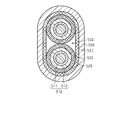
- the individual shield member and the collective shield member are connected as follows. That is, as shown in FIG. 5, a metal tubular member 520 is provided on the outer periphery of the insulating coating 512 that covers the outer periphery of the conductive core wire 511 of the pair of electric wires 510, and the outer periphery of the tubular member 520 is individually shielded. It is covered with a member 530.
- the collective shield member 540 covers the pair of electric wires 510 so as to straddle the outer circumferences of both individual shield members 530.
- each individual shield member 530 and the collective shield member 540 are pressed between the band member 550 and the tubular member 520, and each individual shield member 530 and the collective shield member 530 are collectively shielded.
- the member 540 is electrically connected.
- the collective shield member 540 mounted so as to straddle the individual shield members 530 of the adjacent electric wires 510 is provided only in the half-circumferential portion on the side opposite to the side where the two adjacent individual shield members 530 face each other. , Contact the two adjacent individual shield members 530.
- the collective shield member 540 does not contact the individual shield member 530, and a relatively large empty space gap 560 is formed. Therefore, the inventor of the present application notices that the contact area between each individual shield member 530 and the collective shield member 540 is narrow, and the resistance force against the displacement of the individual shield member 530 and the collective shield member 540 in the length direction is relatively low. It was.
- the wire harness of the present disclosure is composed of a plurality of electric wires and a braided wire in which conductive strands are woven into a tubular shape, and a plurality of individual shield members that are electromagnetically shielded by individually covering the plurality of electric wires, and conductive.
- a tubular collective shield member composed of a braided wire in which a sex wire is woven into a tubular shape and electromagnetically shielded by collectively covering the plurality of electric wires, and the plurality of individual shield members and the collective shield member.
- the connecting member is provided on the outer periphery of a portion of the collective shield member that overlaps with the plurality of individual shield members, and the connecting member is provided with a connecting member that is electrically connected in a stacked state. It has a protruding portion that protrudes between the plurality of electric wires that are adjacent to each other.
- FIG. 1 is a schematic configuration diagram illustrating a typical configuration example of the wire harness according to the embodiment.
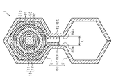
- FIG. 2 is an enlarged cross-sectional view for explaining an enlarged portion A of FIG.
- FIG. 3 is a cross-sectional view taken along the line 3-3 of FIG.
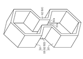
- FIG. 4 is a perspective view illustrating the connecting member.
- FIG. 5 is a cross-sectional view illustrating a wire harness of a reference example.
- the wire harness of the present disclosure is [1] A plurality of individual shield members composed of a plurality of electric wires and a braided wire in which conductive wires are woven into a tubular shape, and electromagnetically shielded by individually covering the plurality of electric wires, and a conductive wire.
- the connecting member is provided on the outer periphery of a portion of the collective shield member that overlaps with the individual shield member, and projects from the plurality of electric wires adjacent to each other. It is a wire harness having a part.
- the connecting member has a protruding portion in which a part of the connecting member is pushed toward between the adjacent electric wires, including the collective shield member mounted over the individual shield members of each electric wire. That is, since the protruding portion of the connecting member exists in the gap generated between the individual shield members of the adjacent electric wires, the contact range is widened to a range in which the collective shield member wraps around each individual shield member and exceeds half a circumference. It becomes possible to do. Further, it is possible to suppress the electric wire and the individual shield member from being deformed to the gap side and escaping when the connecting member is crimped or the like, and it is possible to suppress a decrease in the tightening force. Therefore, the adhesive force between the individual shield member and the collective shield member can be strengthened, and the resistance force against the misalignment between the individual shield member and the collective shield member can be increased.
- the protruding portion has a first protruding portion and a second protruding portion, and the first protruding portion and the second protruding portion face each other in a direction orthogonal to the arrangement direction of the plurality of electric wires. It is good to have it.
- the collective shield member is pushed from both sides of the first protruding portion and the second protruding portion facing each other. That is, since the first protruding portion and the second protruding portion of the connecting member exist in each of the gaps generated between the individual shield members of the adjacent electric wires, the contact range between each individual shield member and the collective shield member is sufficiently widened. It becomes possible to do.
- the connecting member when the connecting member is crimped or the like, the electric wire and the individual shield member can be suppressed from being deformed to the gap side and escaping at each protruding portion, and the decrease in the tightening force can be suppressed more reliably. Therefore, the contact pressure between each individual shield member and the collective shield member can be made stronger.
- first protruding portion and the second protruding portion have facing surfaces that are planes parallel to the arrangement direction of the plurality of electric wires.
- the facing surfaces of the first protruding portion and the second protruding portion for pushing the collective shield member into each other are a plane parallel to the arranging direction of the plurality of electric wires, that is, a plane orthogonal to the pushing direction. Therefore, when the first protruding portion and the second protruding portion push the collective shield member, damage to the collective shield member can be suppressed.
- the facing surfaces of the first protruding portion and the second protruding portion are separated from each other at a set interval so that the portions of the collective shield member interposed between the facing surfaces do not come into contact with each other. It is good to do it. Appropriate spaces can be obtained between the parts of the collective shield member that are interposed between the facing surface of the first protruding portion and the facing surface of the second protruding portion in pairs, and damage to the collective shield member can be suppressed. Because it can be done.
- the connecting member has a plurality of polygonal tubular portions corresponding to the plurality of individual shield members, and the plurality of polygonal tubular portions project along the arrangement direction of the plurality of electric wires. It is preferable that the shape is connected via a portion.
- the polygonal tubular part of the connecting member is tightened by caulking the collective shield member and each individual shield member, the electric wire, the individual shield member, and the collective shield member follow the shape of a cylinder to a polygon. Since it is accompanied by slight deformation, the contact pressure between each other can be partially increased. Therefore, it is possible to increase the resistance to the misalignment between the individual shield member and the collective shield member.
- a plurality of tubular members are provided for individually inserting the plurality of electric wires, and the tubular member is interposed between the plurality of electric wires at a position where the connecting member is provided and the individual shield member. It is good to have it.
- tightening such as caulking with the connecting member including the collective shield member can be performed using the tubular member as a base, thereby increasing the contact pressure between the individual shield member and the collective shield member. Can be done.
- the wire harness 1 shown in FIG. 1 is routed along a route including under the floor of a vehicle such as a hybrid vehicle or an electric vehicle, and electrically connects a plurality of devices to each other.
- the wire harness 1 is provided with a plurality of electric wires 10 and one end side (left end side of FIG. 1) of each electric wire 10, and a plurality of wire harnesses 10 for individually attaching each electric wire 10 to an apparatus.
- the individual connector 21 is provided on the other end side (right end side in FIG. 1) of each electric wire 10, and one collective connector 22 for collectively attaching each electric wire 10 to an apparatus is provided.
- the electric wire 10 has a conductive core wire 11 and a tubular insulating coating 12 that covers the outer periphery of the core wire 11.
- the core wire 11 is, for example, a stranded wire formed by twisting a plurality of metal strands made of a copper alloy.
- the insulating coating 12 is formed by extrusion molding an insulating material such as polyvinyl chloride (PVC).
- the wire harness 1 is provided with a plurality of individual shield members 31 that are electromagnetically shielded by individually covering the plurality of electric wires 10.
- the individual shield member 31 is made of a braided wire in which a conductive wire made of an aluminum alloy or the like is woven into a tubular shape, and has flexibility.
- One end of the individual shield member 31 is electrically connected to the individual connector 21.
- the other end 31b of the individual shield member 31 extends to an intermediate portion in the length direction of the electric wire 10.
- each electric wire 10 is provided with a sheath 13 that individually covers the individual shield member 31.
- the sheath 13 is made of an insulating material such as polyvinyl chloride (PVC).
- PVC polyvinyl chloride
- One end of the sheath 13 is connected to the individual connector 21.
- the other end 13b of the sheath 13 extends to an intermediate portion in the length direction of the electric wire 10.
- the sheath 13 is covered with a flexible tubular first exterior member 41.
- the first exterior member 41 is, for example, a bellows tubular corrugated tube.
- the other end 31b of the individual shield member 31 is exposed from the other end 13b of the sheath 13 and the end of the first exterior member 41.
- the wire harness 1 is provided with one collective shield member 32 that electromagnetically shields a plurality of electric wires 10 by collectively covering them.
- the collective shield member 32 is made of a braided wire in which a conductive wire made of an aluminum alloy or the like is woven into a tubular shape, and has flexibility.
- One end 32a of the collective shield member 32 is electrically connected to the collective connector 22 (see FIG. 1). Further, the other end 32b of the collective shield member 32 extends to an intermediate portion in the length direction of the electric wire 10.
- the collective shield member 32 is covered with a flexible tubular second exterior member 42.
- the second exterior member 42 is, for example, a bellows tubular corrugated tube.
- the outer diameter and inner diameter of the second exterior member 42 are smaller than the outer diameter and inner diameter of the first exterior member 41, respectively.
- the other end 32b of the collective shield member 32 is exposed from the end of the second exterior member 42.
- connection portion 32c the portion of the collective shield member 32 exposed from the second exterior member 42 covers the portion of each individual shield member 31 exposed from the sheath 13.
- connection portion 32c the portion of the collective shield member 32 that is electrically connected to each individual shield member 31 by covering each individual shield member 31.
- each individual shield member 31 is located outside the second exterior member 42. Further, the other end 32b of the collective shield member 32 is located inside the first exterior member 41.
- the wire harness 1 is provided with a plurality of tubular members 50 through which a plurality of electric wires 10 are individually inserted.
- Each tubular member 50 is provided in a portion of each electric wire 10 where the individual shield member 31 is covered by the collective shield member 32. That is, each tubular member 50 is provided at a position corresponding to the connecting portion 32c of the collective shield member 32 in the length direction of the electric wire 10.
- the individual shield member 31 has a folded-back portion 31c at a position corresponding to the connecting portion 32c.
- the tubular member 50 is interposed between the electric wire 10 and the individual shield member 31 so as to be wrapped by the folded-back portion 31c.
- the tubular member 50 is preferably made of a rigid metal material, for example, made of brass.
- the wire harness 1 is provided with a connecting member 60 that electrically connects each individual shield member 31 and the collective shield member 32 in a stacked state.
- the connecting member 60 is provided on the outer periphery of a portion of the collective shield member 32 that covers a plurality of individual shield members 31. That is, the connecting member 60 covers the outer peripheral surface of the connecting portion 32c of the collective shield member 32 over the entire circumference.
- the connecting member 60 is preferably made of a rigid metal material, and is formed by, for example, processing an aluminum sheet metal.
- the connecting member 60 has a plurality of polygonal tubular portions (for example, hexagonal tubular portions 61) corresponding to the plurality of individual shield members 31, and two hexagons along the arrangement direction of the plurality of electric wires 10.
- the tubular portion 61 has a hollow shape in which the tubular portions 61 are connected via a pair of protruding portions 62.
- Each projecting portion 62 projects toward between the electric wires 10 adjacent to each other.
- the pair of projecting portions 62 has a first projecting portion 63 and a second projecting portion 64 facing the first projecting portion 63 in a direction orthogonal to the arrangement direction of the plurality of electric wires 10.
- the first protruding portion 63 has a first facing surface 63a which is a plane parallel to the arrangement direction of the plurality of electric wires 10.
- the second protruding portion 64 has a second facing surface 64a which is a plane parallel to the arrangement direction of the plurality of electric wires 10.
- the facing surfaces 63a and 64a of the first protruding portion 63 and the second protruding portion 64 are spaced apart from each other so that the portions of the collective shield members 32 that are interposed between the facing surfaces 63a and 64a do not come into contact with each other. It is separated by.
- the connecting member 60 has a protruding portion 62 in which a part of the connecting member 60 is pushed toward between the adjacent electric wires 10 including the collective shield member 32 mounted over the individual shield member 31 of each electric wire 10. .. That is, since the protruding portion 62 of the connecting member 60 exists in the gap (corresponding to the gap 560 in FIG. 5) generated between the individual shield members 31 of the adjacent electric wires 10, the collective shield member 32 is provided for each individual shield member 31. It is possible to widen the contact range to a range where the wire wraps around and exceeds half a circumference.
- the contact pressure between the individual shield member 31 and the collective shield member 32 can be increased, and the resistance force against the misalignment between the individual shield member 31 and the collective shield member 32 can be increased.
- the collective shield member 32 is pushed from both sides of the first protruding portion 63 and the second protruding portion 64 facing in a direction orthogonal to the arrangement direction of the plurality of electric wires 10. That is, since the first protruding portion 63 and the second protruding portion 64 of the connecting member 60 exist in each of the gaps generated between the individual shield members 31 of the adjacent electric wires 10, each of the individual shield members 31 and the collective shield member It is possible to sufficiently widen the contact area with the 32.
- the connecting member 60 when the connecting member 60 is tightened by caulking, the electric wire 10 and the individual shield member 31 can be suppressed from being deformed to the gap side and escaping at the protruding portions 63 and 64, and the decrease in the tightening force can be more reliably suppressed. Therefore, the contact pressure between the individual shield member 31 and the collective shield member 32 can be made stronger.
- the facing surfaces 63a and 64a on which the first protruding portion 63 and the second protruding portion 64 push the collective shield member 32, respectively, are flat surfaces parallel to the arranging direction of the plurality of electric wires 10, that is, orthogonal to the pushing direction. It has a flat surface. Therefore, when the first protruding portion 63 and the second protruding portion 64 push the collective shield member 32, damage to the collective shield member 32 can be suppressed.
- the facing surfaces 63a and 64a of the first protruding portion 63 and the second protruding portion 64 are set so that the portions of the collective shield member 32 that are interposed between the facing surfaces 63a and 64a in a pair do not come into contact with each other. Has an interval L. Therefore, an appropriate space can be obtained between the portions of the collective shield member 32, and damage to the collective shield member 32 can be suppressed.
- the hexagonal tubular portion 61 of the connecting member 60 is tightened by caulking the collective shield member 32 and each individual shield member 31. Then, since the electric wire 10, the individual shield member 31, and the collective shield member 32 are slightly deformed from a cylindrical shape to a hexagonal tubular shape, the contact pressure between them can be partially increased. Therefore, the resistance force against the misalignment between the individual shield member 31 and the collective shield member 32 can be increased.
- the connecting member 60 including the collective shield member 32 can be tightened by caulking based on the tubular member 50, so that the individual shield member 31 and the collective shield can be shielded together.
- the contact pressure with the member 32 can be increased.
- the tubular member 50 may be interposed between the insulating coating 12 and the individual shield member 31 so as to slip under the individual shield member 31.
- -It may be applied to a wire harness 1 having three or more electric wires 10.
- the connecting member 60 of the embodiment may be referred to as a metal plate loop member.
- the protruding portion 62 of the connecting member 60 of the embodiment may be referred to as a narrowed neck portion of the metal plate loop member.
- the first protruding portion 63 and the second protruding portion 64 of the connecting member 60 of the embodiment may be referred to as two metal crosslinked plates of the metal plate loop member.
- the wire harness (1) is A plurality of electric wires (10), each having a conductive core wire (11), an insulating coating (12), and a first end and a second end.
- a plurality of individual shield cylinders (31) extending from the first end of the plurality of electric wires (10) and covering the first length portions of the plurality of insulating coatings (12) of the plurality of electric wires (10).
- a single bundle extending from the second end of the plurality of electric wires (10) and collectively covering the second length portion of the bundle of the plurality of insulating coatings (12) of the plurality of electric wires (10).
- the metal plate loop member (60) is A plurality of tubular portions (61) corresponding to the plurality of electric wires (10), and A narrowed neck portion (62) that is continuous with the plurality of tubular portions (61) and bridges the plurality of tubular portions (61) and is narrowed in the lateral direction orthogonal to the axial direction of the plurality of electric wires (10). And can be included.
- each tubular portion (61) of the metal plate loop member (60) has a first hollow portion having an inner diameter larger than the diameter of the corresponding electric wire (10). It is possible, The narrowed neck portion (62) is two metal cross-linked plates (63, 64) continuous with two adjacent tubular portions (61), and is separated by a distance smaller than the inner diameter of the first hollow portion. The two metal cross-linked plates (63, 64) that are separated from each other can be included.
- the metal plate loop member (60) has the single collective shield cylinder (32) in the plurality of tubular portions (61) excluding the narrowed neck portion (62).
- the inner surface of the individual shield cylinder (31) may be configured to face or press against the outer surface of each of the plurality of individual shield cylinders (31).
- the narrowed neck portion (62) of the metal plate loop member (60) may be narrowed by plastic deformation.
- the tubular portion (61) may be a hexagonal tubular portion (61).
- the plurality of individual shielded cylinders (31) are formed between the first end of the plurality of electric wires (10) and the first end and the second end.
- a plurality of insulating coatings (12) of the plurality of electric wires (10) may be covered over the axial position (31b) of 1.
- the single collective shielded cylinder (32) extends from the second end of the plurality of electric wires (10) to a second axial position (32b) between the first end and the second end.
- a bundle of the plurality of insulating coatings (12) of the plurality of electric wires (10) may be collectively covered.
- the single batch shield cylinder (32) is in direct contact with each of the plurality of individual shield cylinders (31) with a first axial length (31b-32b). You can do it.
- the metal plate loop member (60) has a second axial length equal to or shorter than the first axial length (31b-32b). You can do it.
- each of the plurality of tubular individual shield members (31) is a first flexible tubular braided member, and the single tubular collective shield member (1). 32) may be a second flexible tubular braided member.
- each of the plurality of tubular individual shield members (31) may have a smaller diameter than the single tubular collective shield member (32).
- the metal plate loop member (60) may be a metal one-piece product.
- the plurality of conductive core wires (11) of the plurality of electric wires (10) are connected to a plurality of individual connectors (21) at the first end of the plurality of electric wires (10).
- the plurality of conductive core wires (11) of the plurality of electric wires (10) may be collectively connected to a common single connector (22) at the second end of the plurality of electric wires (10). May be connected.
Landscapes
- Insulated Conductors (AREA)
- Engineering & Computer Science (AREA)
- Mechanical Engineering (AREA)
Abstract
ワイヤハーネス1は、複数の電線10を個別に覆い電磁シールドする複数の個別シールド部材31と、複数の電線10を一括して覆い電磁シールドする筒状の一括シールド部材32とを備える。複数の個別シールド部材31と一括シールド部材32とを互いに重ねた状態で接続部材60が複数の個別シールド部材31と一括シールド部材32とを締付けて複数の個別シールド部材31と一括シールド部材32とを電気的に接続する。接続部材60は、一括シールド部材32における複数の個別シールド部材31と重なる部分の外周に設けられる。接続部材60は、互いに隣り合う電線10の間に向かって突出する突出部62を有する。
Description
本開示は、ワイヤハーネスに関する。
従来、例えば車両用のワイヤハーネスにおいては、電線への通電に伴い発生する電磁ノイズを遮蔽するために、シールド部材によって電線が覆われている。シールド部材は、例えば、アルミニウム合金などの導電性の素線が筒状に編み込まれた編組線からなり、可撓性を有している。こうしたシールド部材としては、電線の絶縁被覆の外周をシールド部材で個別に覆う個別シールド部材(例えば、特許文献1参照)と、複数の電線を1つのシールド部材で一括して覆う一括シールド部材(例えば、特許文献2参照)とが知られている。なお、個別シールド部材や一括シールド部材の端部は、ワイヤハーネスのコネクタに電気的に接続される。そして、コネクタが車両の機器の筐体などに接続されることで個別シールド部材及び一括シールド部材がアース接続される。
ところで、個別シールド部材と一括シールド部材とを備えるワイヤハーネスにおいて、個別シールド部材と一括シールド部材とがワイヤハーネスの長さ方向の異なる位置に設けられる場合、個別シールド部材と一括シールド部材とを電気的に接続する必要がある。
例えば、特許文献3には、個別シールド部材と一括シールド部材とは以下のように接続される。すなわち、図5に示すように、一対の電線510の導電性芯線511の外周を覆う絶縁被覆512の外周に金属製の筒状部材520が設けられ、更にその筒状部材520の外周が個別シールド部材530に覆われている。一括シールド部材540は、一対の電線510を覆う両個別シールド部材530の外周をまたがるように覆う。一括シールド部材540の外周をバンド部材550で締付けることで、バンド部材550と筒状部材520との間で各個別シールド部材530と一括シールド部材540とが押圧され、各個別シールド部材530と一括シールド部材540とが電気的に接続される。
しかしながら、従来技術では、隣接の電線510の個別シールド部材530にまたがるように装着される一括シールド部材540は、隣接する2つの個別シールド部材530が互いに対向する側とは反対側の半周部分のみにおいて、当該隣接する2つの個別シールド部材530と接触する。言い換えると、隣接の個別シールド部材530が互いに対向する残りの半周部分では、一括シールド部材540は個別シールド部材530と接触せず、比較的大きな空の空間隙間560となっている。そのため、各個別シールド部材530と一括シールド部材540との接触面積が狭く、個別シールド部材530と一括シールド部材540との長さ方向における位置ずれに対する抵抗力が比較的低いことに本願発明者は気づいた。
そこで、個別シールド部材と一括シールド部材との位置ずれの発生を抑制することができるワイヤハーネスを提供することを目的とする。
本開示のワイヤハーネスは、複数の電線と、導電性の素線が筒状に編み込まれた編組線からなり、前記複数の電線を個別に覆うことで電磁シールドする複数の個別シールド部材と、導電性の素線が筒状に編み込まれた編組線からなり、前記複数の電線を一括して覆うことで電磁シールドする筒状の一括シールド部材と、前記複数の個別シールド部材と前記一括シールド部材とを重ねた状態で電気的に接続する接続部材と、を備え、前記接続部材は、前記一括シールド部材における前記複数の個別シールド部材との重なる部分の外周に設けられており、前記接続部材は、互いに隣り合う前記複数の電線同士の間に向かって突出する突出部を有する。
本開示によれば、個別シールド部材と一括シールド部材との位置ずれの発生を抑制することができるワイヤハーネスを提供することが可能となる。
[本開示の実施形態の説明]
最初に本開示の実施形態を列記して説明する。
最初に本開示の実施形態を列記して説明する。
本開示のワイヤハーネスは、
[1]複数の電線と、導電性の素線が筒状に編み込まれた編組線からなり、前記複数の電線を個別に覆うことで電磁シールドする複数の個別シールド部材と、導電性の素線が筒状に編み込まれた編組線からなり、前記複数の電線を一括して覆うことで電磁シールドする筒状の一括シールド部材と、前記個別シールド部材と前記一括シールド部材とを重ねた状態で電気的に接続する接続部材と、を備え、前記接続部材は、前記一括シールド部材における前記個別シールド部材と重なる部分の外周に設けられ、互いに隣り合う前記複数の電線同士の間に向かって突出する突出部を有するワイヤハーネスである。
[1]複数の電線と、導電性の素線が筒状に編み込まれた編組線からなり、前記複数の電線を個別に覆うことで電磁シールドする複数の個別シールド部材と、導電性の素線が筒状に編み込まれた編組線からなり、前記複数の電線を一括して覆うことで電磁シールドする筒状の一括シールド部材と、前記個別シールド部材と前記一括シールド部材とを重ねた状態で電気的に接続する接続部材と、を備え、前記接続部材は、前記一括シールド部材における前記個別シールド部材と重なる部分の外周に設けられ、互いに隣り合う前記複数の電線同士の間に向かって突出する突出部を有するワイヤハーネスである。
各電線の個別シールド部材にまたがって装着される一括シールド部材を含め、接続部材はその一部が互いに隣り合う電線同士の間に向かって押し込まれる突出部を有する。すなわち、隣接の電線の個別シールド部材同士の間に生じる隙間に接続部材の突出部が存在するため、各個別シールド部材それぞれに一括シールド部材が回り込んで半周を超えるような範囲まで接触範囲を広くすることが可能となる。また、接続部材のかしめ等の締付け時に電線及び個別シールド部材が隙間側に変形して逃げることも抑制でき、締付け力の低下も抑制できる。よって、個別シールド部材と一括シールド部材との固着力を強くすることができ、個別シールド部材と一括シールド部材との位置ずれに対する抵抗力を高めることが可能となる。
[2]前記突出部は、第1突出部と第2突出部とを有し、前記第1突出部と前記第2突出部とは、前記複数の電線の並び方向と直交する方向に対向していると良い。一括シールド部材は、互いに対向する第1突出部と第2突出部との両側から押し込まれる。すなわち、隣接の電線の個別シールド部材同士の間に生じる隙間それぞれに接続部材の第1突出部と第2突出部とが存在するため、各個別シールド部材と一括シールド部材との接触範囲を十分広くすることが可能となる。また、接続部材のかしめ等の締付け時に電線及び個別シールド部材が隙間側に変形して逃げることも各突出部にて抑制でき、締付け力の低下もより確実に抑制できる。よって、各個別シールド部材と一括シールド部材との接触圧力をより強いものとすることができるからである。
[3]前記第1突出部と前記第2突出部とは、前記複数の電線の並び方向と平行な平面である対向面を有すると良い。第1突出部と第2突出部とが一括シールド部材をそれぞれ押し込む互いの対向面が複数の電線の並び方向と平行な平面、すなわちその押し込み方向と直交する平面となっている。このため、第1突出部と第2突出部とが一括シールド部材を押し込む際、一括シールド部材の損傷を抑制することができるからである。
[4]前記第1突出部と前記第2突出部の前記対向面は、前記対向面の間に対をなして介在する前記一括シールド部材の部位同士が接触しないように設定された間隔で離隔していると良い。第1突出部の対向面と第2突出部の対向面との間に対をなして介在する一括シールド部材の部位同士に互いに適度なスペースが得られ、一括シールド部材の損傷を抑制することができるからである。
[5]前記接続部材は、前記複数の個別シールド部材にそれぞれ対応する複数の多角形筒状部を有し、前記複数の電線の並び方向に沿って前記複数の多角形筒状部が前記突出部を介して連接された形状であると良い。接続部材の多角形筒状部にて一括シールド部材と各個別シールド部材とのかしめ等による締付けが行われると、電線及び個別シールド部材、更には一括シールド部材が円筒状から多角形筒状に倣った若干の変形を伴うため、部分的に相互間の接触圧力を高めることができる。よって、個別シールド部材と一括シールド部材との位置ずれに対する抵抗力を高めることができるからである。
[6]前記複数の電線に個別に挿通させるための複数の筒状部材を備え、前記筒状部材は、前記接続部材を設ける位置の前記複数の電線と前記個別シールド部材との間に介在されていると良い。筒状部材により電線を保護できることに加え、一括シールド部材を含めた接続部材によるかしめ等の締付けを筒状部材を土台にして行えることで、個別シールド部材と一括シールド部材との接触圧力を高めることができる。
[本開示の実施形態の詳細]
本開示のワイヤハーネスの具体例を、以下に図面を参照しつつ説明する。なお、本発明はこれらの例示に限定されるものではなく、特許請求の範囲によって示され、特許請求の範囲と均等の意味および範囲内でのすべての変更が含まれることが意図される。図面では、説明の便宜上、構成の一部を誇張又は簡略化して示す場合がある。また、各部分の寸法比率についても、実際と異なる場合がある。
本開示のワイヤハーネスの具体例を、以下に図面を参照しつつ説明する。なお、本発明はこれらの例示に限定されるものではなく、特許請求の範囲によって示され、特許請求の範囲と均等の意味および範囲内でのすべての変更が含まれることが意図される。図面では、説明の便宜上、構成の一部を誇張又は簡略化して示す場合がある。また、各部分の寸法比率についても、実際と異なる場合がある。
図1に示すワイヤハーネス1は、例えばハイブリッド車や電気自動車などの車両の床下を含む経路に配索されるとともに、複数の機器同士を電気的に接続する。
図1及び図2に示すように、ワイヤハーネス1は、複数の電線10と、各電線10の一端側(図1の左端側)に設けられ、各電線10を個別に機器に取り付けるための複数の個別コネクタ21と、各電線10の他端側(図1の右端側)に設けられ、各電線10を一括して機器に取り付けるための1つの一括コネクタ22とを備えている。
図2の右側に示すように、電線10は、導電性芯線11と芯線11の外周を覆う筒状の絶縁被覆12とを有している。芯線11は、例えば、銅合金からなる複数の金属素線を撚り合わせて形成される撚り線である。絶縁被覆12は、例えば、ポリ塩化ビニル(PVC)などの絶縁材料を押出成形することにより形成されている。
<個別シールド部材31>
図2に示すように、ワイヤハーネス1には、複数の電線10を個別に覆うことで電磁シールドする複数の個別シールド部材31が設けられている。個別シールド部材31は、例えば、アルミニウム合金などからなる導電性の素線が筒状に編み込まれた編組線からなり、可撓性を有している。個別シールド部材31の一端部は、個別コネクタ21に電気的に接続されている。個別シールド部材31の他端部31bは、電線10の長さ方向における途中の部分まで延びている。
図2に示すように、ワイヤハーネス1には、複数の電線10を個別に覆うことで電磁シールドする複数の個別シールド部材31が設けられている。個別シールド部材31は、例えば、アルミニウム合金などからなる導電性の素線が筒状に編み込まれた編組線からなり、可撓性を有している。個別シールド部材31の一端部は、個別コネクタ21に電気的に接続されている。個別シールド部材31の他端部31bは、電線10の長さ方向における途中の部分まで延びている。
また、各電線10には、個別シールド部材31を個別に被覆するシース13が設けられている。シース13は、例えば、ポリ塩化ビニル(PVC)などの絶縁材料からなる。シース13の一端部は、個別コネクタ21に接続されている。シース13の他端部13bは、電線10の長さ方向における途中の部分まで延びている。
シース13は、可撓性を有する筒状の第1外装部材41により覆われている。第1外装部材41は、例えば、蛇腹筒状のコルゲートチューブである。
個別シールド部材31の他端部31bは、シース13の他端部13b及び第1外装部材41の端部から露出している。
<一括シールド部材32>
図1及び図2に示すように、ワイヤハーネス1には、複数の電線10を一括して覆うことで電磁シールドする1つの一括シールド部材32が設けられている。一括シールド部材32は、例えば、アルミニウム合金などからなる導電性の素線が筒状に編み込まれた編組線からなり、可撓性を有している。一括シールド部材32の一端部32aは、一括コネクタ22に電気的に接続されている(図1参照)。また、一括シールド部材32の他端部32bは、電線10の長さ方向における途中の部分まで延びている。
図1及び図2に示すように、ワイヤハーネス1には、複数の電線10を一括して覆うことで電磁シールドする1つの一括シールド部材32が設けられている。一括シールド部材32は、例えば、アルミニウム合金などからなる導電性の素線が筒状に編み込まれた編組線からなり、可撓性を有している。一括シールド部材32の一端部32aは、一括コネクタ22に電気的に接続されている(図1参照)。また、一括シールド部材32の他端部32bは、電線10の長さ方向における途中の部分まで延びている。
一括シールド部材32は、可撓性を有する筒状の第2外装部材42により覆われている。第2外装部材42は、例えば、蛇腹筒状のコルゲートチューブである。ただし、第2外装部材42の外径及び内径は、第1外装部材41の外径及び内径よりもそれぞれ小さい。
一括シールド部材32の他端部32bは、第2外装部材42の端部から露出している。
図2に示すように、一括シールド部材32のうち第2外装部材42から露出した部分は、各個別シールド部材31のうちシース13から露出した部分を覆っている。以下、一括シールド部材32のうち各個別シールド部材31を覆うことで各個別シールド部材31に電気的に接続される部分を接続部32cと称する。
ここで、各個別シールド部材31の他端部31bは、第2外装部材42の外部に位置している。また、一括シールド部材32の他端部32bは、第1外装部材41の内部に位置している。
<筒状部材50>
図2及び図3に示すように、ワイヤハーネス1には、複数の電線10が個別に挿通される複数の筒状部材50が設けられている。各筒状部材50は、各電線10のうち個別シールド部材31が一括シールド部材32により覆われる部分に設けられている。すなわち、各筒状部材50は、電線10の長さ方向における一括シールド部材32の接続部32cに対応する位置に設けられている。個別シールド部材31は、接続部32cに対応する位置において、折返し部31cを有している。筒状部材50は、折返し部31cによって包み込まれるように、電線10と個別シールド部材31との間に介在している。筒状部材50は、剛性を有する金属材料であることが好ましく、例えば真鍮により形成されている。
図2及び図3に示すように、ワイヤハーネス1には、複数の電線10が個別に挿通される複数の筒状部材50が設けられている。各筒状部材50は、各電線10のうち個別シールド部材31が一括シールド部材32により覆われる部分に設けられている。すなわち、各筒状部材50は、電線10の長さ方向における一括シールド部材32の接続部32cに対応する位置に設けられている。個別シールド部材31は、接続部32cに対応する位置において、折返し部31cを有している。筒状部材50は、折返し部31cによって包み込まれるように、電線10と個別シールド部材31との間に介在している。筒状部材50は、剛性を有する金属材料であることが好ましく、例えば真鍮により形成されている。
<接続部材60>
図2~図4に示すように、ワイヤハーネス1には、各個別シールド部材31と一括シールド部材32とを重ねた状態で電気的に接続する接続部材60が設けられている。接続部材60は、一括シールド部材32のうち複数の個別シールド部材31を覆う部分の外周に設けられている。すなわち、接続部材60は、一括シールド部材32の接続部32cの外周面を全周にわたって覆っている。接続部材60は、剛性を有する金属材料であることが好ましく、例えばアルミニウムの板材が板金加工されることによって形成されている。接続部材60は、複数の個別シールド部材31にそれぞれ対応する複数の多角形筒状部(例えば、六角形筒状部61)を有し、複数の電線10の並び方向に沿って2つの六角形筒状部61が一対の突出部62を介して連接された中空形状である。
図2~図4に示すように、ワイヤハーネス1には、各個別シールド部材31と一括シールド部材32とを重ねた状態で電気的に接続する接続部材60が設けられている。接続部材60は、一括シールド部材32のうち複数の個別シールド部材31を覆う部分の外周に設けられている。すなわち、接続部材60は、一括シールド部材32の接続部32cの外周面を全周にわたって覆っている。接続部材60は、剛性を有する金属材料であることが好ましく、例えばアルミニウムの板材が板金加工されることによって形成されている。接続部材60は、複数の個別シールド部材31にそれぞれ対応する複数の多角形筒状部(例えば、六角形筒状部61)を有し、複数の電線10の並び方向に沿って2つの六角形筒状部61が一対の突出部62を介して連接された中空形状である。
各突出部62は、互いに隣り合う電線10同士の間に向かって突出している。一対の突出部62は、第1突出部63と、複数の電線10の並び方向と直交する方向において第1突出部63と対向する第2突出部64と、を有している。第1突出部63は、複数の電線10の並び方向と平行な平面である第1対向面63aを有している。第2突出部64は、複数の電線10の並び方向と平行な平面である第2対向面64aを有している。第1突出部63と第2突出部64の対向面63a、64aは、対向面63a、64aの間に対をなして介在する一括シールド部材32の部位同士が接触しないように設定された間隔Lにて離隔している。
以上説明したように、本実施形態によれば、以下の作用効果を奏することができる。
(1)各電線10の個別シールド部材31にまたがって装着される一括シールド部材32を含め、接続部材60はその一部が互いに隣り合う電線10同士の間に向かって押し込まれる突出部62を有する。すなわち、隣接の電線10の個別シールド部材31同士の間に生じる隙間(図5の隙間560に相当)に接続部材60の突出部62が存在するため、各個別シールド部材31それぞれに一括シールド部材32が回り込んで半周を超えるような範囲まで接触範囲を広くすることが可能となる。また、接続部材60のかしめによる締付け時に電線10及び個別シールド部材31が隙間側に変形して逃げることも抑制でき、締付け力の低下も抑制できる。よって、個別シールド部材31と一括シールド部材32との接触圧力を強くすることができ、個別シールド部材31と一括シールド部材32との位置ずれに対する抵抗力を高めることができる。
(2)一括シールド部材32は、複数の電線10の並び方向と直交する方向に対向する第1突出部63と第2突出部64との両側から押し込まれる。すなわち、隣接の電線10の個別シールド部材31同士の間に生じる隙間それぞれに接続部材60の第1突出部63と第2突出部64とが存在するため、各個別シールド部材31それぞれと一括シールド部材32との接触面積を十分広くすることが可能となる。また、接続部材60のかしめによる締付け時に電線10及び個別シールド部材31が隙間側に変形して逃げることも各突出部63、64にて抑制でき、締付け力の低下もより確実に抑制できる。よって、個別シールド部材31と一括シールド部材32との接触圧力をより強いものとすることができる。
(3)第1突出部63と第2突出部64とが一括シールド部材32をそれぞれ押し込む互いの対向面63a、64aは、複数の電線10の並び方向と平行な平面、すなわちその押し込み方向と直交する平面をなしている。このため、第1突出部63と第2突出部64とが一括シールド部材32を押し込む際、一括シールド部材32の損傷を抑制することができる。
(4)第1突出部63と第2突出部64の対向面63a、64aは、対向面63a、64aの間に対をなして介在する一括シールド部材32の部位同士が接触しないように設定された間隔Lを有する。このため、一括シールド部材32のその部位同士に互いに適度なスペースが得られ、一括シールド部材32の損傷を抑制することができる。
(5)接続部材60の六角形筒状部61にて一括シールド部材32と各個別シールド部材31とのかしめによる締付けが行われる。すると、電線10及び個別シールド部材31、更には一括シールド部材32が円筒状から六角形筒状に倣った若干の変形を伴うため、部分的に相互間の接触圧力を高めることができる。よって、個別シールド部材31と一括シールド部材32との位置ずれに対する抵抗力を高めることができる。
(6)筒状部材50により電線10を保護できることに加え、一括シールド部材32を含めた接続部材60のかしめによる締付けを筒状部材50を土台にして行えることで、個別シールド部材31と一括シールド部材32との接触圧力を高めることができる。
(7)剛性を有する金属製(板金製)の接続部材60により一括シールド部材32をかしめることで、結束バンドのような締付け部材を割愛することができる。
なお、上記実施形態は、以下のように変更して実施することができる。上記実施形態及び以下の変更例は技術的に矛盾しない範囲で組み合わせて実施することができる。
・筒状部材50は、個別シールド部材31の下にもぐり込ませるように、絶縁被覆12と個別シールド部材31との間に介在されていてもよい。
・3本以上の電線10を有するワイヤハーネス1に適用してもよい。
・実施形態の接続部材60は、金属板ループ部材と呼称することがある。実施形態の接続部材60の突出部62は、金属板ループ部材の狭窄首部と呼称することがある。実施形態の接続部材60の第1突出部63及び第2突出部64は、金属板ループ部材の2つの金属架橋板と呼称することがある。
本開示は以下の実装例を包含する。限定のためでなく理解の補助として図示した実施形態の代表的な構成要素の参照符号を付した。
[付記1]本開示の一以上の実装例に従うワイヤハーネス(1)は、
各々が導電性芯線(11)と絶縁被覆(12)と第1端と第2端とを有する複数の電線(10)と、
前記複数の電線(10)の前記第1端から延出し、前記複数の電線(10)の複数の絶縁被覆(12)の第1の長さ部分をそれぞれ覆う複数の個別シールド筒(31)と、
前記複数の電線(10)の前記第2端から延出し、前記複数の電線(10)の前記複数の絶縁被覆(12)の束の第2の長さ部分を一括して覆う単一の一括シールド筒(32)と、
前記複数の電線(10)の前記第1端と前記第2端との間の所定の軸方向中間位置(32c)において前記単一の一括シールド筒(32)の外側に設けられた金属板ループ部材(60)とを備えることができ、
前記金属板ループ部材(60)は、前記所定の軸方向中間位置(32c)において前記単一の一括シールド筒(32)を前記複数の個別シールド筒(31)に電気的に接続するように構成されており、
前記複数の電線(10)の軸方向に直交する断面視において、前記金属板ループ部材(60)は、
前記複数の電線(10)にそれぞれ対応する複数の筒状部(61)と、
前記複数の筒状部(61)と連続して前記複数の筒状部(61)を架橋し、前記複数の電線(10)の軸方向に直交する横方向に狭窄された狭窄首部(62)とを含むことができる。
各々が導電性芯線(11)と絶縁被覆(12)と第1端と第2端とを有する複数の電線(10)と、
前記複数の電線(10)の前記第1端から延出し、前記複数の電線(10)の複数の絶縁被覆(12)の第1の長さ部分をそれぞれ覆う複数の個別シールド筒(31)と、
前記複数の電線(10)の前記第2端から延出し、前記複数の電線(10)の前記複数の絶縁被覆(12)の束の第2の長さ部分を一括して覆う単一の一括シールド筒(32)と、
前記複数の電線(10)の前記第1端と前記第2端との間の所定の軸方向中間位置(32c)において前記単一の一括シールド筒(32)の外側に設けられた金属板ループ部材(60)とを備えることができ、
前記金属板ループ部材(60)は、前記所定の軸方向中間位置(32c)において前記単一の一括シールド筒(32)を前記複数の個別シールド筒(31)に電気的に接続するように構成されており、
前記複数の電線(10)の軸方向に直交する断面視において、前記金属板ループ部材(60)は、
前記複数の電線(10)にそれぞれ対応する複数の筒状部(61)と、
前記複数の筒状部(61)と連続して前記複数の筒状部(61)を架橋し、前記複数の電線(10)の軸方向に直交する横方向に狭窄された狭窄首部(62)とを含むことができる。
[付記2]一以上の実装例において、前記金属板ループ部材(60)の各筒状部(61)は、対応する電線(10)の直径よりも大きい内径を有する第1の中空部を有することができ、
前記狭窄首部(62)は、隣接する2つの筒状部(61)に連続する2つの金属架橋板(63,64)であって、前記第1の中空部の前記内径よりも小さい離間距離だけ互いに離間する前記2つの金属架橋板(63,64)を含むことができる。
前記狭窄首部(62)は、隣接する2つの筒状部(61)に連続する2つの金属架橋板(63,64)であって、前記第1の中空部の前記内径よりも小さい離間距離だけ互いに離間する前記2つの金属架橋板(63,64)を含むことができる。
[付記3]一以上の実装例において、前記金属板ループ部材(60)は、前記狭窄首部(62)を除く前記複数の筒状部(61)において、前記単一の一括シールド筒(32)の内面を前記複数の個別シールド筒(31)の各々の外面に対面させるかまたは押圧するように構成されてよい。
[付記4]一以上の実装例において、前記金属板ループ部材(60)の前記狭窄首部(62)は、可塑変形によって狭窄されてよい。
[付記5]一以上の実装例において、前記筒状部(61)は、六角形筒状部(61)であってよい。
[付記6]一以上の実装例において、前記複数の個別シールド筒(31)は、前記複数の電線(10)の前記第1端から、前記第1端と前記第2端との間の第1の軸方向位置(31b)にわたって前記複数の電線(10)の複数の絶縁被覆(12)をそれぞれ覆ってよく、
前記単一の一括シールド筒(32)は、前記複数の電線(10)の前記第2端から、前記第1端と前記第2端との間の第2の軸方向位置(32b)にわたって前記複数の電線(10)の前記複数の絶縁被覆(12)の束を一括して覆ってよい。
前記単一の一括シールド筒(32)は、前記複数の電線(10)の前記第2端から、前記第1端と前記第2端との間の第2の軸方向位置(32b)にわたって前記複数の電線(10)の前記複数の絶縁被覆(12)の束を一括して覆ってよい。
[付記7]一以上の実装例において、前記単一の一括シールド筒(32)は、前記複数の個別シールド筒(31)の各々と第1の軸方向長さ(31b-32b)をもって直接接触してよい。
[付記8]一以上の実装例において、前記金属板ループ部材(60)は、前記第1の軸方向長さ(31b-32b)と同じかそれよりも短い第2の軸方向長さを有してよい。
[付記9]一以上の実装例において、前記複数の筒状の個別シールド部材(31)の各々は、第1の柔軟な筒状編組部材であり、前記単一の筒状の一括シールド部材(32)は、第2の柔軟な筒状編組部材であってよい。
[付記10]一以上の実装例において、前記複数の筒状の個別シールド部材(31)の各々は、前記単一の筒状の一括シールド部材(32)よりも小径であってよい。
[付記11]一以上の実装例において、前記金属板ループ部材(60)は、金属ワンピース品であってよい。
[付記12]一以上の実装例において、前記複数の電線(10)の複数の導電性芯線(11)は、前記複数の電線(10)の前記第1端において、複数の個別コネクタ(21)にそれぞれ接続されてよく、前記複数の電線(10)の複数の導電性芯線(11)は、前記複数の電線(10)の前記第2端において、共通の単一コネクタ(22)に一括して接続されてよい。
1…ワイヤハーネス
10…電線
11…芯線
12…絶縁被覆
13…シース
13b…他端部
21…個別コネクタ
22…一括コネクタ
31…個別シールド部材
31b…他端部
31c…折返し部
32…一括シールド部材
32a…一端部
32b…他端部
32c…接続部
41…第1外装部材
42…第2外装部材
50…筒状部材
60…接続部材
61…多角形筒状部としての六角形筒状部
62…突出部
63…第1突出部
63a…第1対向面
64…第2突出部
64a…第2対向面
L…間隔
10…電線
11…芯線
12…絶縁被覆
13…シース
13b…他端部
21…個別コネクタ
22…一括コネクタ
31…個別シールド部材
31b…他端部
31c…折返し部
32…一括シールド部材
32a…一端部
32b…他端部
32c…接続部
41…第1外装部材
42…第2外装部材
50…筒状部材
60…接続部材
61…多角形筒状部としての六角形筒状部
62…突出部
63…第1突出部
63a…第1対向面
64…第2突出部
64a…第2対向面
L…間隔
Claims (6)
- 複数の電線と、
導電性の素線が筒状に編み込まれた編組線からなり、前記複数の電線を個別に覆うことで電磁シールドする複数の個別シールド部材と、
導電性の素線が筒状に編み込まれた編組線からなり、前記複数の電線を一括して覆うことで電磁シールドする筒状の一括シールド部材と、
前記複数の個別シールド部材と前記一括シールド部材とを重ねた状態で電気的に接続する接続部材と、を備え、
前記接続部材は、前記一括シールド部材における前記複数の個別シールド部材と重なる部分の外周に設けられており、前記接続部材は、互いに隣り合う前記複数の電線同士の間に向かって突出する突出部を有するワイヤハーネス。 - 請求項1に記載のワイヤハーネスであって、
前記突出部は、第1突出部と第2突出部とを有し、
前記第1突出部と前記第2突出部とは、前記複数の電線の並び方向と直交する方向に対向しているワイヤハーネス。 - 請求項2に記載のワイヤハーネスであって、
前記第1突出部と前記第2突出部とは、前記複数の電線の並び方向と平行な平面である対向面を有するワイヤハーネス。 - 請求項3に記載のワイヤハーネスであって、
前記第1突出部と前記第2突出部の前記対向面は、前記対向面の間に対をなして介在する前記一括シールド部材の部位同士が接触しないように設定された間隔で離隔しているワイヤハーネス。 - 請求項1から請求項4の何れか1項に記載のワイヤハーネスであって、
前記接続部材は、前記複数の個別シールド部材にそれぞれ対応する複数の多角形筒状部を有し、前記複数の電線の並び方向に沿って前記複数の多角形筒状部が前記突出部を介して連接された形状であるワイヤハーネス。 - 請求項1から請求項5の何れか1項に記載のワイヤハーネスであって、
前記複数の電線に個別に挿通させるための複数の筒状部材を備え、
前記複数の筒状部材は、前記接続部材を設ける位置の前記複数の電線と前記複数の個別シールド部材との間に介在されているワイヤハーネス。
Applications Claiming Priority (2)
| Application Number | Priority Date | Filing Date | Title |
|---|---|---|---|
| JP2019-052535 | 2019-03-20 | ||
| JP2019052535A JP7159933B2 (ja) | 2019-03-20 | 2019-03-20 | ワイヤハーネス |
Publications (1)
| Publication Number | Publication Date |
|---|---|
| WO2020188933A1 true WO2020188933A1 (ja) | 2020-09-24 |
Family
ID=72519029
Family Applications (1)
| Application Number | Title | Priority Date | Filing Date |
|---|---|---|---|
| PCT/JP2019/050490 Ceased WO2020188933A1 (ja) | 2019-03-20 | 2019-12-24 | ワイヤハーネス |
Country Status (2)
| Country | Link |
|---|---|
| JP (1) | JP7159933B2 (ja) |
| WO (1) | WO2020188933A1 (ja) |
Citations (3)
| Publication number | Priority date | Publication date | Assignee | Title |
|---|---|---|---|---|
| JP2006164613A (ja) * | 2004-12-03 | 2006-06-22 | Yazaki Corp | シールド電線のアース処理方法及びアース処理構造 |
| JP2008204804A (ja) * | 2007-02-20 | 2008-09-04 | Auto Network Gijutsu Kenkyusho:Kk | 車両用シールド導電体 |
| JP2013240204A (ja) * | 2012-05-15 | 2013-11-28 | Auto Network Gijutsu Kenkyusho:Kk | ワイヤハーネス |
Family Cites Families (1)
| Publication number | Priority date | Publication date | Assignee | Title |
|---|---|---|---|---|
| JP6788802B2 (ja) | 2017-05-26 | 2020-11-25 | 住友電装株式会社 | ワイヤハーネス |
-
2019
- 2019-03-20 JP JP2019052535A patent/JP7159933B2/ja active Active
- 2019-12-24 WO PCT/JP2019/050490 patent/WO2020188933A1/ja not_active Ceased
Patent Citations (3)
| Publication number | Priority date | Publication date | Assignee | Title |
|---|---|---|---|---|
| JP2006164613A (ja) * | 2004-12-03 | 2006-06-22 | Yazaki Corp | シールド電線のアース処理方法及びアース処理構造 |
| JP2008204804A (ja) * | 2007-02-20 | 2008-09-04 | Auto Network Gijutsu Kenkyusho:Kk | 車両用シールド導電体 |
| JP2013240204A (ja) * | 2012-05-15 | 2013-11-28 | Auto Network Gijutsu Kenkyusho:Kk | ワイヤハーネス |
Also Published As
| Publication number | Publication date |
|---|---|
| JP2020155307A (ja) | 2020-09-24 |
| JP7159933B2 (ja) | 2022-10-25 |
Similar Documents
| Publication | Publication Date | Title |
|---|---|---|
| US9325120B2 (en) | Wire harness and connection structure of shield shell and braided shield | |
| EP2685466A3 (en) | Cable assembly | |
| JP6270089B2 (ja) | 導電部材 | |
| WO2020026884A1 (ja) | ワイヤハーネス | |
| JP6641575B2 (ja) | 導電路とシールド部材とのズレ防止構造、及びワイヤハーネス | |
| CN103477499A (zh) | 用于同轴电缆的屏蔽端子 | |
| WO2015034034A1 (ja) | 多芯ケーブルおよび多芯ケーブルの製造方法 | |
| US10965113B2 (en) | Wire harness | |
| US20190126861A1 (en) | Wire harness | |
| US20130319720A1 (en) | Protector, method of manufacturing the protector, and shield conductor | |
| JP6515996B2 (ja) | ワイヤハーネス | |
| WO2019188100A1 (ja) | ワイヤハーネス | |
| JP2010040214A (ja) | 集合ケーブルの接地部材及び接地方法並びに集合ケーブル組立体 | |
| WO2014148446A1 (ja) | 電線のシールド構造 | |
| WO2020188933A1 (ja) | ワイヤハーネス | |
| JP6011521B2 (ja) | ワイヤーハーネス | |
| WO2019188098A1 (ja) | ワイヤハーネス | |
| JP2015072883A (ja) | ワイヤーハーネス | |
| JP7771873B2 (ja) | コネクタ付きケーブル | |
| TW201703365A (zh) | 同軸連接器 | |
| JP6831205B2 (ja) | シールド部材、及び、シールド電線 | |
| KR20190081692A (ko) | 고전압 케이블의 차폐접지부 및 그 제조방법 | |
| WO2022244528A1 (ja) | ワイヤハーネス | |
| KR20260045189A (ko) | 플렉서블 버스바를 이용한 고전압 하네스 장치 | |
| WO2023276661A1 (ja) | 接続端子、および、接続端子付電線 |
Legal Events
| Date | Code | Title | Description |
|---|---|---|---|
| 121 | Ep: the epo has been informed by wipo that ep was designated in this application |
Ref document number: 19919561 Country of ref document: EP Kind code of ref document: A1 |
|
| NENP | Non-entry into the national phase |
Ref country code: DE |
|
| 122 | Ep: pct application non-entry in european phase |
Ref document number: 19919561 Country of ref document: EP Kind code of ref document: A1 |