WO2020188757A1 - ユーザ装置 - Google Patents
ユーザ装置 Download PDFInfo
- Publication number
- WO2020188757A1 WO2020188757A1 PCT/JP2019/011509 JP2019011509W WO2020188757A1 WO 2020188757 A1 WO2020188757 A1 WO 2020188757A1 JP 2019011509 W JP2019011509 W JP 2019011509W WO 2020188757 A1 WO2020188757 A1 WO 2020188757A1
- Authority
- WO
- WIPO (PCT)
- Prior art keywords
- user device
- preamble
- message
- unit
- header
- Prior art date
- Legal status (The legal status is an assumption and is not a legal conclusion. Google has not performed a legal analysis and makes no representation as to the accuracy of the status listed.)
- Ceased
Links
Images




Classifications
-
- H—ELECTRICITY
- H04—ELECTRIC COMMUNICATION TECHNIQUE
- H04W—WIRELESS COMMUNICATION NETWORKS
- H04W72/00—Local resource management
- H04W72/12—Wireless traffic scheduling
- H04W72/1263—Mapping of traffic onto schedule, e.g. scheduled allocation or multiplexing of flows
-
- H—ELECTRICITY
- H04—ELECTRIC COMMUNICATION TECHNIQUE
- H04W—WIRELESS COMMUNICATION NETWORKS
- H04W76/00—Connection management
- H04W76/10—Connection setup
- H04W76/14—Direct-mode setup
-
- H—ELECTRICITY
- H04—ELECTRIC COMMUNICATION TECHNIQUE
- H04W—WIRELESS COMMUNICATION NETWORKS
- H04W74/00—Wireless channel access
- H04W74/08—Non-scheduled access, e.g. ALOHA
- H04W74/0833—Random access procedures, e.g. with 4-step access
-
- H—ELECTRICITY
- H04—ELECTRIC COMMUNICATION TECHNIQUE
- H04W—WIRELESS COMMUNICATION NETWORKS
- H04W92/00—Interfaces specially adapted for wireless communication networks
- H04W92/16—Interfaces between hierarchically similar devices
- H04W92/18—Interfaces between hierarchically similar devices between terminal devices
Definitions
- the present invention relates to a user device in a wireless communication system.
- Non-Patent Document 1 In LTE (Long Term Evolution) and LTE successor systems (for example, LTE-A (LTE Advanced), NR (New Radio) (also called 5G)), communication devices such as UEs directly communicate with each other without going through the base station gNB.
- LTE-A Long Term Evolution Advanced
- NR New Radio
- a side link also called D2D (Device to Device)
- D2D Device to Device
- V2X Vehicle to Everything
- V2X is a part of ITS (Intelligent Transport Systems), V2V (Vehicle to Vehicle) which means a communication form performed between automobiles, and a roadside machine (RSU: Road) installed between an automobile and a roadside.
- ITS Intelligent Transport Systems
- V2V Vehicle to Vehicle
- RSU Road
- -V2I Vehicle to Infrastructure
- V2N Vehicle to Nomadic device
- V2P Vehicle to Pedestrian
- V2P Vehicle to Pedestrian
- the following channels are included in the channels for direct communication between terminals used in direct communication between terminals (side link technology).
- the channel for transmitting control information such as SCI (Siderink Control Information) is referred to as PSCCH (Physical Sidelink Control Channel), and the channel for transmitting data is referred to as PSCH (Physical Sidelink Sharp Channel).
- PSCCH Physical Sidelink Control Channel
- PSCH Physical Sidelink Sharp Channel
- HARQ Hybrid Automatic Repeat Request
- SFCI Sidelink Feedback Control Information
- the SFCI is transmitted on the terminal-to-terminal direct communication feedback channel (Physical Sidelink Feedback Channel (PSFCH)).
- the header user device is a member user in a user device group (UE group) composed of a header user device (header-UE) and a member user device (member-UEs). Scheduling for the device has been proposed.
- the transmission mode may be referred to as a side link transmission mode 2-d, or may have a different name.
- the header user device may be called a scheduling user device or the like, and the member user device may be called a non-header user device, a non-scheduling user device, or the like.
- the present invention has been made in view of the above points, and an object of the present invention is to provide a technique for defining a procedure of a wireless layer in forming a user device group in direct communication between terminals.
- the present invention is not limited to terminal-to-terminal communication in V2X, and may be applied to any terminal.
- a user device having a transmitting unit that transmits a preamble to another user device and a receiving unit that receives a response to the preamble from the other user device.
- a technology for defining a procedure of a wireless layer in forming a user device group is provided.
- FIG. 1 is a diagram for explaining four types of side link transmission modes in NR-V2X.
- the user device 20A transmits PSCCH / PSCH to the user device 20B based on the SL scheduling by the base station device 10.
- PSCCH / PSSCH transmission is performed based on the resource selection of the user device itself.
- the side link transmission mode 2 of the NR-V2X is further subdivided.
- the user device 20A is transferred to the user device 20B based on the resource selection of the user device 20A itself.
- the PSCCH / PSCH is transmitted to the user device A, and the user device 20B transmits the PSCCH / PSCH to the user device A based on the resource selection of the user device 20B itself.
- the user device 20A is sent to the user device 20B according to the RRC-config of the resource pattern (resource pattern) notified from the base station device 10 or determined by the specification.
- PSSCH is transmitted to the PSCH.
- the user apparatus 20A performs scheduling for transmission of the user apparatus 20B by transmitting SL scheduling to the user apparatus 20B, and the user apparatus 20B performs scheduling for transmission thereof.
- PSCCH / PSCH is transmitted to the user apparatus 20A based on the scheduling.
- a user device group (User device group) A user device group (UE group) will be described.
- FIG. 2 is a diagram for explaining a user device group.
- resource allocation UE-scheduling based resource allocation
- the header user device 20H is determined.
- the member user device 20M is associated with the header user device 20H (ie, forms a user device group).
- the resource (resource (s)) / resource set (resource set (s)) used for each user device group is determined.
- the header user device 20H schedules the resources in the resource set assigned to the user device group to the member user device 20M.
- resource interference between user device groups can be reduced by allocating resource sets orthogonal to each other to a plurality of adjacent user device groups.
- each header user device 20H performs independent scheduling. Also, the scheduler algorithm depends on the implementation of the user device. At the time of scheduling, a procedure including a side link scheduling request and a notification indicating a scheduled resource is assumed.
- FIG. 3 is a diagram for explaining a wireless access procedure in LTE / NR Uu.
- a synchronization signal SSB Synchronization Signal Block
- SS Synchronization Signal
- PBCH Physical Broadcast Channel
- Message 3 (Message 3 (Msg.3)) is transmitted from the user apparatus 20 to the base station apparatus 10 on a PUSCH (Physical Uplink Shared Channel) scheduled by UL grant included in RAR. 4.
- a message 4 (Message 4 (Msg.4)) is transmitted from the base station apparatus 10 to the user apparatus 20 on the PDSCH (Physical Downlink Shared Channel).
- the DCI is scrambled by RA-RNTI (Random Access-Radio Network Temporary Identifier).
- RA-RNTI Random Access-Radio Network Temporary Identifier
- downlink allocation is transmitted on the PDCCH and higher layer signaling is transmitted on the corresponding PDSCH.
- the upper layer signaling includes a RAR UL grant that schedules an uplink data channel (PUSCH).
- FIG. 4 is a diagram for explaining a wireless access procedure in the present embodiment.
- the following operations are executed between the user device 20 and the header user device 20H.
- a signal corresponding to the preamble in the LTE / NR Uu wireless access procedure is transmitted from the user device 20 to the header user device 20H.
- a signal corresponding to RAR in the LTE / NR Uu wireless access procedure is transmitted from the header user device 20H to the user device 20.
- a signal corresponding to message 3 (Message 3 (Msg.3)) in the LTE / NR Uu wireless access procedure is transmitted from the user device 20 to the header user device 20H.
- a signal corresponding to message 4 (Message 4 (Msg.4)) in the LTE / NR Uu wireless access procedure is transmitted from the header user device to the user device.
- the message 3 may be read as, for example, a PSCCH scheduled by a PSCCH scrambled by a specific RNTI (for example, SL-RAR-V-RNTI) or a PSCH scheduled by a signal corresponding to RAR. It may have a different name.
- the message 4 may be read as, for example, a PSCCH scrambled by a specific RNTI and / or a PSCCH assigned by the PSCCH, or may have a different name.
- the user device 20 that needs to be associated with the predetermined header user device 20H transmits random access signaling (eg, preamble / sequence).
- the user device 20 may autonomously select a predetermined preamble / series from a plurality of preambles / series that can be associated with the header user device 20H.
- the predetermined preamble / series includes an identifier of the header user device 20H (for example, UE ID / RNTI, SSID (Service Set Identity), resource set ID (resource set ID), user device group / cluster ID (UE-group / grouper ID)). ), A virtual ID (for example, an ID having the same function as the cell ID), or a part thereof).
- a set of virtual IDs can be defined, and a certain virtual ID may be set (in advance) or selected by the header user device 20H. Similar to the cell ID, the virtual ID may be notified by the header user device 20H, for example, via PSBCH (Physical Sidelink Broadcast Channel). In this way, the orthogonality of preambles of different user equipment groups can be achieved.
- PSBCH Physical Sidelink Broadcast Channel
- FIG. 5 is a diagram for explaining a preamble that is orthogonal between user device groups.
- the user device group 1 of the header user device 1 (20H1) uses the preamble set 1 (preamble set 1)
- the user device group 2 of the header user device 2 (20H2) uses the preamble set 2 (preamble set 1). Orthogonality is realized by using set2).
- the user device 20 uses the information represented by the S-SSB (Sidelink-Synchronization Signal Block) from the header user device 20H, eg, a preamble / using sequence and / or time frequency resources. You may select a series.
- S-SSB Segment-Synchronization Signal Block
- a side link preamble transmission channel that is, SL-PRACH (Sidelink PHY Random Access Channel) is used as a dedicated channel corresponding to PRACH (Physical Random Access Channel) in the LTE / NR Uu wireless access procedure. ) May be set (in advance).
- the conditions A for triggering the preamble transmission by the user device 20 are as follows: (1) When the user device 20 is not associated with any header user device 20H, (2) The user device 20 is associated with the header user. When changing the device 20H, (3) the user device 20 can be associated with a plurality of header user devices 20H, and the number of header user devices 20H already associated can be associated with the header user device 20H. It is conceivable that the maximum number of is not reached.
- the conditions B for triggering the preamble transmission by the user device 20 are as follows: (1) When the user device 20 receives the S-SSB from the header user device 20H that can be associated, (2) the header user that can be associated. It is conceivable that the power measurement obtained from the S-SSB or other reference signal (RS (Reference Signal)) from the device 20H exceeds a (preliminarily) set threshold value.
- RS Reference Signal
- the user device may transmit the preamble on the corresponding SL-PRACH resource.
- the S-SSB transmitted from the header user device 20H may include information indicating that the header user device 20H can be the header user device 20H.
- the header user device 20H detects the preamble by monitoring the SL-PRACH resource.
- the header user device 20H transmits RAR signaling to the user device 20 that has detected the preamble.
- the RAR signaling may include at least a resource allocation of resources (for example, PSCCH / PSCH resources) corresponding to the resources for transmitting LTE / NR Uu message 3.
- resources for example, PSCCH / PSCH resources
- the temporary SL-RNTI (Siderink RNTI) assigned by the header user device 20H may also be transmitted by RAR signaling.
- the SL-RNTI can be used to scramble at least the messages corresponding to LTE / NR Uu messages 3 and 4. Further, the resource allocation of the resource corresponding to the resource for transmitting the LTE / NR Uu message 3 may be included in the upper layer signaling.
- the physical channel that transmits RAR can be at least one of PSCCH and PSCCH assigned by PSCCH.
- the PSCCH, and the PSCCH assigned by the PSCCH may be scrambled by individual RNTIs (eg, RNTIs based on the detected preamble time frequency resource location or sequence ID). Also, the PSCCH, and the PSCCH assigned by the PSCCH, may explicitly include the ID of the time-frequency resource location or sequence of the detected preamble.
- the RAR transmission may be executed, for example, during a specified time interval (time interval) after the preamble is detected, or a (pre-) set time interval (time interval).
- the user device 20 For reception of RAR, the user device 20 that has transmitted the preamble is specified or (in advance) to monitor RAR signaling for a period of time specified or (pre-) set for RAR transmission. ) May be set. Further, if the RAR is not received during the time interval, the preamble may be retransmitted.
- the user apparatus 20 that has transmitted the preamble and decrypted the corresponding RAR signaling feeds back at least the user apparatus ID (UE ID) on the resource corresponding to the assigned message 3.
- a message corresponding to message 3 may carry information for PC5-RRC connection / resume between the header user device 20H and the member user device 20M.
- the header user device 20H resolves a random access / association collision by transmitting a message corresponding to message 4 after decoding the message corresponding to message 3.
- the transmission of the message corresponding to the message 4 may be executed, for example, during a specified or (pre-) set time interval (time interval) after the message corresponding to the message 3 is received.
- the user device 20 that has transmitted the message corresponding to the message 3 may monitor the message corresponding to the message 4 during a specified or (preliminarily) set time interval (time interval).
- the message corresponding to the message 4 may include at least a user device ID (UE ID) that can be associated with the header user device 20H.
- UE ID user device ID
- the SL-SR (Sidelink-Scheduling Request) resource for the associated user device 20 may be carried by a message corresponding to message 4.
- Information for PC5-RRC connection / resume between the header user device 20H and the member user device 20M may be carried by a message corresponding to message 4.
- the message corresponding to message 4 may be transmitted on PSCCH / PSCH. Also, the resource for the message corresponding to message 4 may be scheduled by the header user apparatus 20H and notified (eg, by notification via PSCCH).
- the signaling notifying the resource for the message corresponding to message 4 may at least reflect the destination of the signaling (for example, it may be scrambled based on the destination ID, and the destination ID is explicitly included in the signaling. May be).
- the above procedure provides a technique for defining a radio layer procedure that associates the user device 20 with the header user device 20H.
- the base station apparatus 10 and the user apparatus 20 include a function of carrying out the above-described embodiment.
- the base station apparatus 10 and the user apparatus 20 may each have only a part of the functions in the embodiment.
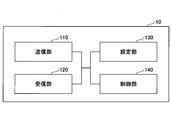
- FIG. 6 is a diagram showing an example of the functional configuration of the base station apparatus 10.
- the base station apparatus 10 includes a transmission unit 110, a reception unit 120, a setting unit 130, and a control unit 140.
- the functional configuration shown in FIG. 6 is only an example. Any function classification and name of the functional unit may be used as long as the operation according to the embodiment of the present invention can be performed.
- the transmission unit 110 includes a function of generating a signal to be transmitted to the user device 20 side and transmitting the signal wirelessly. Further, the transmission unit 110 transmits information such as SL scheduling to the user device 20.
- the receiving unit 120 includes a function of receiving various signals transmitted from the user apparatus 20 and acquiring information of, for example, a higher layer from the received signals.
- the setting unit 130 stores preset setting information and various setting information to be transmitted to the user device 20 in the storage device, and reads them out from the storage device as needed.
- the content of the setting information is, for example, information related to the setting of V2X.
- control unit 140 performs processing related to the setting for the user device 20 to perform V2X. Further, the function unit related to signal transmission in the control unit 140 may be included in the transmission unit 110, and the function unit related to signal reception in the control unit 140 may be included in the reception unit 120.
- FIG. 7 is a diagram showing an example of the functional configuration of the user device 20.
- the user device 20 includes a transmission unit 210, a reception unit 220, a setting unit 230, and a control unit 240.
- the functional configuration shown in FIG. 7 is only an example. Any function classification and name of the functional unit may be used as long as the operation according to the embodiment of the present invention can be performed.
- the transmission unit 210 creates a transmission signal from the transmission data and wirelessly transmits the transmission signal.
- the receiving unit 220 wirelessly receives various signals and acquires a signal of a higher layer from the received signal of the physical layer.
- the receiving unit 220 has a function of receiving the SL scheduling transmitted from the base station apparatus 10.
- the receiving unit 220 as the receiving unit 220 of the header user device 20H, has a function of receiving a preamble or a message corresponding to the message 3 transmitted from another user device.
- the transmission unit 210 has a function of transmitting a message corresponding to RAR or message 4 to another user device 20 as the transmission unit 210 of the header user device 20H.
- the receiving unit 220 has a function of receiving a message corresponding to RAR or message 4 transmitted from another user device as a receiving unit 220 of the member user device 20M.
- the transmission unit 210 has a function of transmitting a preamble or a message corresponding to the message 3 to another user device 20 as the transmission unit 210 of the member user device 20M.
- the setting unit 230 stores various setting information received from the base station device 10 or the user device 20 by the receiving unit 220 in the storage device, and reads it out from the storage device as needed.
- the setting unit 230 also stores preset setting information.
- the content of the setting information is, for example, information related to V2X and HARQ processing.
- the control unit 240 controls the D2D communication executed with the other user device 20 as described in the embodiment. In addition, the control unit 240 executes a wireless access procedure with another user device 20.
- the function unit related to signal transmission in the control unit 240 may be included in the transmission unit 210, and the function unit related to signal reception in the control unit 240 may be included in the reception unit 220.
- each functional block may be realized by one device in which a plurality of elements are physically and / or logically combined, or two or more devices physically and / or logically separated from each other directly and. / Or indirectly (eg, wired and / or wireless) may be connected and realized by these plurality of devices.
- FIG. 8 is a diagram showing an example of the hardware configuration of the wireless communication device which is the base station device 10 or the user device 20 according to the embodiment of the present invention.
- the above-mentioned base station device 10 and user device 20 are physically as computer devices including a processor 1001, a storage device 1002, an auxiliary storage device 1003, a communication device 1004, an input device 1005, an output device 1006, a bus 1007, and the like. It may be configured.
- the word “device” can be read as a circuit, device, unit, etc.
- the hardware configuration of the base station device 10 and the user device 20 may be configured to include one or more of the devices shown by 1001 to 1006 shown in the figure, or may be configured without including some of the devices. May be done.
- the processor 1001 For each function of the base station device 10 and the user device 20, by loading predetermined software (program) on the hardware such as the processor 1001 and the storage device 1002, the processor 1001 performs an calculation and the communication device 1004 communicates. It is realized by controlling the reading and / or writing of data in the storage device 1002 and the auxiliary storage device 1003.
- Processor 1001 operates, for example, an operating system to control the entire computer.
- the processor 1001 may be composed of a central processing unit (CPU: Central Processing Unit) including an interface with a peripheral device, a control device, an arithmetic unit, a register, and the like.
- CPU Central Processing Unit
- the processor 1001 reads a program (program code), a software module or data from the auxiliary storage device 1003 and / or the communication device 1004 into the storage device 1002, and executes various processes according to these.
- a program program that causes a computer to execute at least a part of the operations described in the above-described embodiment is used.
- the transmission unit 110, the reception unit 120, the setting unit 130, and the control unit 140 of the base station device 10 shown in FIG. 6 may be stored in the storage device 1002 and realized by a control program that operates in the processor 1001.
- Processor 1001 may be mounted on one or more chips.
- the program may be transmitted from the network via a telecommunication line.
- the storage device 1002 is a computer-readable recording medium, and is, for example, at least one of ROM (Read Only Memory), EPROM (Erasable Programmable ROM), EPROM (Electrically Erasable Programmable ROM), RAM (Random Access Memory), and the like. It may be configured.
- the storage device 1002 may be referred to as a register, a cache, a main memory (main storage device), or the like.
- the storage device 1002 can store a program (program code), a software module, or the like that can be executed to carry out the process according to the embodiment of the present invention.
- the auxiliary storage device 1003 is a computer-readable recording medium, for example, an optical disk such as a CD-ROM (Compact Disc ROM), a hard disk drive, a flexible disk, a magneto-optical disk (for example, a compact disk, a digital versatile disk, Blu).
- -It may be composed of at least one of a ray (registered trademark) disk), a smart card, a flash memory (for example, a card, a stick, a key drive), a floppy (registered trademark) disk, a magnetic strip, and the like.
- the auxiliary storage device 1003 may be referred to as an auxiliary storage device.
- the storage medium described above may be, for example, a database, server or other suitable medium containing the storage device 1002 and / or the auxiliary storage device 1003.
- the communication device 1004 is hardware (transmission / reception device) for communicating between computers via a wired and / or wireless network, and is also referred to as, for example, a network device, a network controller, a network card, a communication module, or the like.
- the transmission unit 110 and the reception unit 120 of the base station device 10 may be realized by the communication device 1004.
- the transmission unit 210 and the reception unit 220 of the user device 20 may be realized by the communication device 1004.
- the input device 1005 is an input device (for example, a keyboard, a mouse, a microphone, a switch, a button, a sensor, etc.) that receives an input from the outside.
- the output device 1006 is an output device (for example, a display, a speaker, an LED lamp, etc.) that outputs to the outside.
- the input device 1005 and the output device 1006 may have an integrated configuration (for example, a touch panel).
- each device such as the processor 1001 and the storage device 1002 is connected by a bus 1007 for communicating information.
- the bus 1007 may be composed of a single bus or may be composed of different buses between the devices.
- the base station device 10 and the user device 20 are a microprocessor, a digital signal processor (DSP: Digital Signal Processor), an ASIC (Application Specific Integrated Circuit), a PLD (Programmable Logic Device), an FPGA (Field Programmable Gate Array), etc., respectively. It may be configured to include the above hardware, and a part or all of each functional block may be realized by the hardware. For example, processor 1001 may be implemented on at least one of these hardware.
- a user device having a transmitting unit that transmits a preamble to another user device and a receiving unit that receives a response to the preamble from the other user device.
- a user device having a receiving unit that receives a preamble from another user device and a transmitting unit that transmits a response to the preamble to the other user device.
- the operation of the plurality of functional units may be physically performed by one component, or the operation of one functional unit may be physically performed by a plurality of components.
- the order of processing may be changed as long as there is no contradiction.
- the base station apparatus 10 and the user apparatus 20 have been described using functional block diagrams, but such devices may be implemented in hardware, software, or a combination thereof.
- the software operated by the processor of the base station apparatus 10 according to the embodiment of the present invention and the software operated by the processor of the user apparatus 20 according to the embodiment of the present invention are random access memory (RAM), flash memory, and read, respectively. It may be stored in a dedicated memory (ROM), EPROM, EEPROM, registers, hard disk (HDD), removable disk, CD-ROM, database, server or any other suitable storage medium.
- information notification includes physical layer signaling (for example, DCI (Downlink Control Information), UCI (Uplink Control Information)), higher layer signaling (for example, RRC (Radio Resource Control) signaling, MAC (Medium Access Control) signaling, etc. Broadcast information (MIB (Master Information Block), SIB (System Information Block)), other signals or a combination thereof may be used.
- RRC signaling may be referred to as an RRC message, for example, RRC. It may be a connection setup (RRCConnectionSetup) message, an RRC connection reconfiguration (RRCConnectionReconfiguration) message, or the like.
- Each aspect / embodiment described in the present specification includes LTE (LongTermEvolution), LTE-A (LTE-Advanced), SUPER 3G, IMT-Advanced, 4G, 5G, FRA (FutureRadioAccess), W-CDMA. (Registered Trademarks), GSM (Registered Trademarks), CDMA2000, UMB (Ultra-Mobile Broadband), IEEE 802.11 (Wi-Fi), IEEE 802.16 (WiMAX), IEEE 802.20, UWB (Ultra-WideBand), It may be applied to systems utilizing Bluetooth®, other suitable systems and / or next-generation systems extended based on them.
- the specific operation performed by the base station apparatus 10 in the present specification may be performed by its upper node (upper node).
- various operations performed for communication with the user device 20 are other than the base station device 10 and / or the base station device 10. It is clear that it can be done by other network nodes, such as, but not limited to, MME or S-GW.
- MME Mobility Management Entity
- S-GW Serving Mobility Management Entity
- the user device 20 may be a subscriber station, a mobile unit, a subscriber unit, a wireless unit, a remote unit, a mobile device, a wireless device, a wireless communication device, a remote device, a mobile subscriber station, an access terminal, a mobile terminal, etc. It may also be referred to as a wireless terminal, remote terminal, handset, user agent, mobile client, client, or some other suitable term.
- the base station apparatus 10 may be referred to by those skilled in the art by NB (NodeB), eNB (evolvedNodeB), gNB, BaseStation, or some other suitable term.
- NB NodeB
- eNB evolvedNodeB
- gNB BaseStation
- determining and “determining” used in the present specification may include a wide variety of actions.
- “Judgment” and “decision” are, for example, judgment (judging), calculation (calculating), calculation (computing), processing (processing), derivation (deriving), investigating (investigating), searching (looking up) (for example, table). , Searching in a database or another data structure), confirming (ascertaining) may be regarded as “judgment” or “decision”.
- judgment and “decision” are receiving (for example, receiving information), transmitting (for example, transmitting information), input (input), output (output), and access.
- the resource request is an example of a scheduling request
- the resource grant is an example of a scheduling grant
- the scheduling user device is an example of a header user device.
- Base station device 110 Transmission unit 120 Reception unit 130 Setting unit 140 Control unit 20 User device 210 Transmission unit 220 Reception unit 230 Setting unit 240 Control unit 1001 Processor 1002 Storage device 1003 Auxiliary storage device 1004 Communication device 1005 Input device 1006 Output device
Landscapes
- Engineering & Computer Science (AREA)
- Computer Networks & Wireless Communication (AREA)
- Signal Processing (AREA)
- Mobile Radio Communication Systems (AREA)
Abstract
プリアンブルを他のユーザ装置に送信する送信部と、前記プリアンブルに対する応答を前記他のユーザ装置から受信する受信部と、を有するユーザ装置。
Description
本発明は、無線通信システムにおけるユーザ装置に関連するものである。
LTE(Long Term Evolution)及びLTEの後継システム(例えば、LTE-A(LTE Advanced)、NR(New Radio)(5Gとも呼ぶ))では、UE等の通信装置同士が基地局gNBを介さないで直接通信を行うサイドリンク(D2D(Device to Device)とも呼ぶ)技術が検討されている(非特許文献1)。
また、V2X(Vehicle to Everything)を実現することが検討され、仕様化が進められている。ここで、V2Xとは、ITS(Intelligent Transport Systems)の一部であり、自動車間で行われる通信形態を意味するV2V(Vehicle to Vehicle)、自動車と道路脇に設置される路側機(RSU:Road-Side Unit)との間で行われる通信形態を意味するV2I(Vehicle to Infrastructure)、自動車とドライバーのモバイル端末との間で行われる通信形態を意味するV2N(Vehicle to Nomadic device)、及び、自動車と歩行者のモバイル端末との間で行われる通信形態を意味するV2P(Vehicle to Pedestrian)の総称である。
3GPP TS 36.213 V14.3.0(2017-06)
端末間直接通信(サイドリンク技術)において使用される端末間直接通信用チャネルには以下のチャネルが含まれる。
SCI(Sidelink Contol Information)等の制御情報を送信するチャネルはPSCCH(Physical Sidelink Control Channel)と称され、データを送信するチャネルはPSSCH(Physical Sidelink Shared Channel)と称される。また、NRのV2Xでは、PSCCH及びPSCCHに対するHARQ(Hybrid Automatic Repeat Request)動作をサポートすることが規定されており、HARQ-ACKを含む端末間直接通信フィードバック制御情報(Sidelink Feedback Control Information(SFCI))が定義されている。SFCIは、端末間直接通信フィードバックチャネル(Physical Sidelink Feedback Channel(PSFCH))上で送信される。
NR-V2Xのサイドリンク送信モードの一つとして、ヘッダユーザ装置(header-UE)とメンバユーザ装置(member-UEs)で構成されるユーザ装置グループ(UE group)において、ヘッダユーザ装置が、メンバユーザ装置に対してスケジューリングすることが提案されている。上記送信モードはサイドリンク送信モード2-dと呼ばれてもよいし、異なる名称であっても良い。また、ヘッダユーザ装置はスケジューリングユーザ装置などと呼ばれても良いし、メンバユーザ装置は非ヘッダユーザ装置、非スケジューリングユーザ装置などと呼ばれても良い。
サイドリンク送信モード2-dを実現するためのアーキテクチャとして、ヘッダユーザ装置の決定後に、メンバユーザ装置をヘッダユーザ装置と関連付けてユーザ装置グループを形成することが提案されている。
しかしながら、ユーザ装置グループの形成における無線レイヤの手順については明確に規定されていない。
本発明は上記の点に鑑みてなされたものであり、端末間直接通信において、ユーザ装置グループの形成における無線レイヤの手順を規定する技術を提供することを目的とする。なお、本発明はV2Xにおける端末間通信に限られず、いかなる端末に適用されてもよい。
開示の技術によれば、プリアンブルを他のユーザ装置に送信する送信部と、前記プリアンブルに対する応答を前記他のユーザ装置から受信する受信部と、を有するユーザ装置が提供される。
開示の技術によれば、端末間直接通信において、ユーザ装置グループの形成における無線レイヤの手順を規定する技術が提供される。
以下、図面を参照して本発明の実施の形態(本実施の形態)を説明する。なお、以下で説明する実施の形態は一例に過ぎず、本発明が適用される実施の形態は、以下の実施の形態に限られるわけではない。
(サイドリンク送信モード)
NR-V2Xにおけるサイドリンク送信モードについて説明する。
NR-V2Xにおけるサイドリンク送信モードについて説明する。
図1は、NR-V2Xにおける4種類のサイドリンク送信モードを説明するための図である。
NR-V2Xのサイドリンク送信モード1では、ユーザ装置20Aは、基地局装置10によるSLスケジューリングに基づいて、ユーザ装置20Bに対してPSCCH/PSSCHを送信する。
NR-V2Xのサイドリンク送信モード2では、ユーザ装置自身のリソース選択に基づいてPSCCH/PSSCHの送信が行われる。NR-V2Xのサイドリンク送信モード2はさらに細分化されており、NR-V2Xのサイドリンク送信モード2-aでは、ユーザ装置20Aは、ユーザ装置20A自身のリソース選択に基づいて、ユーザ装置20Bに対してPSCCH/PSSCHを送信し、また、ユーザ装置20Bは、ユーザ装置20B自身のリソース選択に基づいて、ユーザ装置Aに対してPSCCH/PSSCHを送信する。NR-V2Xのサイドリンク送信モード2-cでは、基地局装置10から通知される、または仕様で決められた、リソースパターン(resource pattern)のRRC-configに従って、ユーザ装置20Aは、ユーザ装置20Bに対してPSSCHを送信する。
NR-V2Xのサイドリンク送信モード2-dでは、ユーザ装置20Aは、ユーザ装置20Bに対してSL schedulingを送信することにより、ユーザ装置20Bの送信のためのスケジューリングを行い、ユーザ装置20Bは、そのスケジューリングに基づいて、ユーザ装置20Aに対してPSCCH/PSSCHを送信する。
(ユーザ装置グループ)
ユーザ装置グループ(UE group)について説明する。
ユーザ装置グループ(UE group)について説明する。
図2は、ユーザ装置グループを説明するための図である。サイドリンク送信モード2-dを実現するためのアーキテクチャとして、以下に示すようなユーザ装置スケジューリングに基づくリソース割当て(UE-scheduling based resource allocation)が提案されている。
1.ヘッダユーザ装置20Hを決定する。
2.メンバユーザ装置20Mをヘッダユーザ装置20Hと関連付ける(すなわち、ユーザ装置グループを形成する)。
3.ユーザ装置グループ毎に使用されるリソース(resource(s))/リソースセット(resource set(s))を決定する。
4.ヘッダユーザ装置20Hが、ユーザ装置グループに割り当てられたリソースセットの中のリソースをメンバユーザ装置20Mに対してスケジューリングする。
1.ヘッダユーザ装置20Hを決定する。
2.メンバユーザ装置20Mをヘッダユーザ装置20Hと関連付ける(すなわち、ユーザ装置グループを形成する)。
3.ユーザ装置グループ毎に使用されるリソース(resource(s))/リソースセット(resource set(s))を決定する。
4.ヘッダユーザ装置20Hが、ユーザ装置グループに割り当てられたリソースセットの中のリソースをメンバユーザ装置20Mに対してスケジューリングする。
上記3において、近接する複数のユーザ装置グループに対して互いに直交するリソースセットを割当てることにより、ユーザ装置グループ間のリソース干渉を軽減することができる。
上記4において、各ヘッダユーザ装置20Hは、独立したスケジューリングを行うことが想定される。また、スケジューラのアルゴリズムはユーザ装置の実装に依存する。スケジューリングの際には、サイドリンクスケジューリング要求とスケジュールされたリソースを示す通知を含む手順が想定される。
(LTE/NR Uuにおける無線アクセス手順)
本実施形態における無線アクセス手順を説明する前に、LTE/NR Uuにおける無線アクセス手順について説明する。
本実施形態における無線アクセス手順を説明する前に、LTE/NR Uuにおける無線アクセス手順について説明する。
図3は、LTE/NR Uuにおける無線アクセス手順を説明するための図である。
図3に示すように、LTE/NR Uuにおける無線アクセス手順においては、ユーザ装置20と基地局装置10との間で以下の動作が実行される。
0.基地局装置10から同期信号SSB(Synchronization Signal Block)(SS(Synchronaization Signal)/PBCH(Physical Broadcast Channel))を周期的に送信する(不図示)。
1.ユーザ装置20から基地局装置10へ、プリアンブル(Preamble)が送信される。
2.基地局装置10からユーザ装置20へ、無線アクセス応答RAR(Random Access Response)がPDCCH上で送信される。
3.ユーザ装置20から基地局装置10へ、メッセージ3(Message 3(Msg.3))が、RARに含まれるUL grantによってスケジュールされたPUSCH(Physical Uplink Shared Channel)上で送信される。
4.基地局装置10からユーザ装置20へ、メッセージ4(Message 4(Msg.4))がPDSCH(Physical Downlink Shared Channel)上で送信される。
0.基地局装置10から同期信号SSB(Synchronization Signal Block)(SS(Synchronaization Signal)/PBCH(Physical Broadcast Channel))を周期的に送信する(不図示)。
1.ユーザ装置20から基地局装置10へ、プリアンブル(Preamble)が送信される。
2.基地局装置10からユーザ装置20へ、無線アクセス応答RAR(Random Access Response)がPDCCH上で送信される。
3.ユーザ装置20から基地局装置10へ、メッセージ3(Message 3(Msg.3))が、RARに含まれるUL grantによってスケジュールされたPUSCH(Physical Uplink Shared Channel)上で送信される。
4.基地局装置10からユーザ装置20へ、メッセージ4(Message 4(Msg.4))がPDSCH(Physical Downlink Shared Channel)上で送信される。
上記2のPDCCH上で送信されるRARにおいて、DCIはRA-RNTI(Random Access-Radio Network Temporary Identifier)によってスクランブルされる。RARにおいて、下りリンク割当てがPDCCH上で送信され、対応するPDSCH上で上位レイヤシグナリングが送信される。上位レイヤシグナリングには、上りリンクデータチャネル(PUSCH)をスケジューリングするRAR UL grantが含まれる。
(実施形態における無線アクセス手順)
本実施形態における無線アクセス手順を説明する。
本実施形態における無線アクセス手順を説明する。
図4は、本実施形態における無線アクセス手順を説明するための図である。
図4に示すように、本実施形態における無線アクセル手順においては、ユーザ装置20とヘッダユーザ装置20Hとの間で以下の動作が実行される。
1.ユーザ装置20からヘッダユーザ装置20Hへ、LTE/NR Uuの無線アクセス手順におけるプリアンブル(Preamble)に相当する信号が送信される。
2.ヘッダユーザ装置20Hからユーザ装置20へ、LTE/NR Uuの無線アクセス手順におけるRARに相当する信号が送信される。
3.ユーザ装置20からヘッダユーザ装置20Hへ、LTE/NR Uuの無線アクセス手順におけるメッセージ3(Message 3(Msg.3))に相当する信号が送信される。
4.ヘッダユーザ装置からユーザ装置へ、LTE/NR Uuの無線アクセス手順におけるメッセージ4(Message 4(Msg.4))に相当する信号が送信される。
1.ユーザ装置20からヘッダユーザ装置20Hへ、LTE/NR Uuの無線アクセス手順におけるプリアンブル(Preamble)に相当する信号が送信される。
2.ヘッダユーザ装置20Hからユーザ装置20へ、LTE/NR Uuの無線アクセス手順におけるRARに相当する信号が送信される。
3.ユーザ装置20からヘッダユーザ装置20Hへ、LTE/NR Uuの無線アクセス手順におけるメッセージ3(Message 3(Msg.3))に相当する信号が送信される。
4.ヘッダユーザ装置からユーザ装置へ、LTE/NR Uuの無線アクセス手順におけるメッセージ4(Message 4(Msg.4))に相当する信号が送信される。
なお、上記メッセージ3は、例えば、特定のRNTI(例えば、SL-RAR-V-RNTI)によってスクランブリングされたPSCCHによってスケジュールされるPSSCH、あるいはRARに相当する信号によってスケジュールされたPSSCH、と読み替えられてもよいし、別の名称であってもよい。また、上記メッセージ4は、例えば、特定のRNTIによってスクランブリングされたPSCCH且つ/又は前記PSCCHによって割り当てられるPSSCHと読み替えられてもよいし、別の名称であってもよい。
以下、各動作1-4について詳細に説明する。
(プリアンブル)
所定のヘッダユーザ装置20Hとの関連付けを必要とするユーザ装置20は、ランダムアクセスシグナリング(例:プリアンブル(Preamble)/系列(Sequence))を送信する。
所定のヘッダユーザ装置20Hとの関連付けを必要とするユーザ装置20は、ランダムアクセスシグナリング(例:プリアンブル(Preamble)/系列(Sequence))を送信する。
ユーザ装置20は、ヘッダユーザ装置20Hと関連付けられ得る複数のプリアンブル/系列の中から所定のプリアンブル/系列を自律的に選択してもよい。所定のプリアンブル/系列は、ヘッダユーザ装置20Hの識別子(例えば、UE ID/RNTI、SSID(Service Set Identifier)、リソースセットID(resource set ID)、ユーザ装置グループ/クラスタID(UE-group/cluster ID)、仮想ID(virtual ID)(例えば、セルIDと同様の機能をもつID)、またはその一部)であってもよい。ここで、ひと組の仮想IDを定義することが可能であり、ヘッダユーザ装置20Hによって或る仮想IDが、(予め)設定されてもよいし、選択されてもよい。セルIDと同じように、仮想IDはヘッダユーザ装置20Hによって、例えばPSBCH(Physical Sidelink Broadcast Channel)を介して、報知されてもよい。このようにして、異なるユーザ装置グループのプリアンブルの直交性が実現され得る。
図5は、ユーザ装置グループ間で直交するプリアンブルを説明するための図である。図5に示されるように、ヘッダユーザ装置1(20H1)のユーザ装置グループ1ではプリアンブルセット1(preamble set 1)を用い、ヘッダユーザ装置2(20H2)のユーザ装置グループ2ではプリアンブルセット2(preamble set 2)を用いることにより直交性が実現される。
用いられるプリアンブル/系列の代替案として、ユーザ装置20は、ヘッダユーザ装置20HからのS-SSB(Sidelink-Synchronization Signal Block)で示される情報、例えば、系列かつ/または時間周波数リソースを用いたプリアンブル/系列を選択してもよい。
プリアンブルを送信する物理チャネルとしては、LTE/NR Uuの無線アクセス手順におけるPRACH(Physical Random Access Channel)に相当する専用チャネルとして、サイドリンク用プリアンブル送信チャネル、すなわち、SL-PRACH(Sidelink PHY Random Access Channel)が(予め)設定されてもよい。
ユーザ装置20によるプリアンブル送信のトリガーの条件Aとしては、(1)当該ユーザ装置20が、いずれのヘッダユーザ装置20Hとも関連付けられていない場合、(2)当該ユーザ装置20が、関連付けられたヘッダユーザ装置20Hを変更する場合、(3)当該ユーザ装置20が複数のヘッダユーザ装置20Hと関連付けられることが可能であり、すでに関連付けられているヘッダユーザ装置20Hの数が、関連付けられ得るヘッダユーザ装置20Hの最大数に達していない場合等、が考えられる。
条件Aの(1)、(2)、(3)のうちの一つだけが満たされてもよいし、複数が満たされてもよい。
ユーザ装置20によるプリアンブル送信のトリガーの条件Bとしては、(1)当該ユーザ装置20が、関連付けられ得るヘッダユーザ装置20HからのS-SSBを受信している場合、(2)関連付けられ得るヘッダユーザ装置20HからのS-SSBまたは他の参照信号(RS(Reference Signal))から得られる電力測定が(予め)設定された閾値を超えている場合等、が考えられる。
条件Bの(1)、(2)のうちの一つだけが満たされてもよいし両方が満たされてもよい。
ユーザ装置20によるプリアンブル送信のトリガーの条件Aおよび条件Bの1つまたは両方が満たされた場合に、ユーザ装置は、対応するSL-PRACHリソース上でプリアンブルを送信してもよい。
なお、ヘッダユーザ装置20Hから送信されるS-SSBには、ヘッダユーザ装置20Hがヘッダユーザ装置20Hとなり得ることを示す情報が含まれていてもよい。
ユーザ装置20から送信されるプリアンブルの受信については、ヘッダユーザ装置20Hが、SL-PRACHリソースを監視(monitor)することによりプリアンブルを検出することが規定または(予め)設定されてもよい。
(RAR)
ヘッダユーザ装置20Hは、プリアンブルを検出したユーザ装置20に対してRARシグナリングを送信する。
ヘッダユーザ装置20Hは、プリアンブルを検出したユーザ装置20に対してRARシグナリングを送信する。
RARシグナリングには、少なくとも、LTE/NR Uuのメッセージ3送信のためのリソースに相当するリソース(例えば、PSCCH/PSSCHリソース)のリソース割当て(resource grant)が含まれてもよい。
なお、ヘッダユーザ装置20Hによって割り当てられた一時的なSL-RNTI(Sidelink RNTI)も、RARシグナリングによって送信されてもよい。該SL-RNTIは、少なくとも、LTE/NR Uuのメッセージ3およびメッセージ4に相当するメッセージをスクランブルするために使用され得る。また、LTE/NR Uuのメッセージ3送信のためのリソースに相当するリソースのリソース割当て(resource grant)は、上位レイヤシグナリングに含まれてもよい。
RARを送信する物理チャネルは、PSCCH、およびPSCCHによって割り当てられるPSSCHの少なくとも一つであり得る。
PSCCH、およびPSCCHによって割り当てられるPSSCHは、個別のRNTI(例えば、検出されたプリアンブルの時間周波数リソース位置または系列のIDに基づくRNTI)によってスクランブルされてもよい。また、PSCCH、およびPSCCHによって割り当てられるPSSCHは、検出されたプリアンブルの時間周波数リソース位置または系列のIDを明示的に含んでもよい。RARを送信する物理チャネルとしてこのようなPSCCH、およびPSCCHによって割り当てられるPSSCHを用いることにより、メンバユーザ装置20Mとなるユーザ装置20は、該RARが当該ユーザ装置20に対して送信されたものであることを判断し得る。
RARの送信は、例えば、プリアンブル検出後の規定された時間区間(time interval)、または(予め)設定された時間区間(time interval)の間に実行されてもよい。
RARの受信については、プリアンブルを送信したユーザ装置20は、RAR送信のために規定された、または(予め)設定された時間区間の間、RARシグナリングを監視(monitor)することが規定または(予め)設定されてもよい。また、時間区間の間にRARが受信されなかった場合にはプリアンブルの再送が行われてもよい。
(メッセージ3およびメッセージ4)
プリアンブルを送信し、対応するRARシグナリングを復号したユーザ装置20は、割り当てられたメッセージ3相当のリソース上で、少なくともユーザ装置ID(UE ID)をフィードバックする。メッセージ3相当のメッセージによって、ヘッダユーザ装置20Hとメンバユーザ装置20Mとの間のPC5-RRC接続/再開(resume)のための情報が運ばれてもよい。
プリアンブルを送信し、対応するRARシグナリングを復号したユーザ装置20は、割り当てられたメッセージ3相当のリソース上で、少なくともユーザ装置ID(UE ID)をフィードバックする。メッセージ3相当のメッセージによって、ヘッダユーザ装置20Hとメンバユーザ装置20Mとの間のPC5-RRC接続/再開(resume)のための情報が運ばれてもよい。
ヘッダユーザ装置20Hは、メッセージ3相当のメッセージの復号後、メッセージ4相当のメッセージを送信することにより、ランダムアクセス/関連付け衝突(random access/association collision)を解決する。
メッセージ4相当のメッセージの送信は、例えば、メッセージ3相当のメッセージの受信後の、規定された、または(予め)設定された時間区間(time interval)の間に実行されてもよい。
メッセージ3相当のメッセージを送信したユーザ装置20は、規定された、または(予め)設定された時間区間(time interval)の間、メッセージ4相当のメッセージを監視(monitor)してもよい。
メッセージ4相当のメッセージは、少なくとも、ヘッダユーザ装置20Hと関連付け得るユーザ装置ID(UE ID)を含んでもよい。
関連付けられたユーザ装置20のためのSL-SR(Sidelink-Scheduling Request)リソースが、メッセージ4相当のメッセージによって運ばれてもよい。
ヘッダユーザ装置20Hとメンバユーザ装置20Mとの間のPC5-RRC接続/再開(resume)のための情報が、メッセージ4相当のメッセージによって運ばれてもよい。
メッセージ4相当のメッセージは、PSCCH/PSSCH上で送信されてもよい。また、メッセージ4相当のメッセージのためのリソースは、ヘッダユーザ装置20Hによってスケジュールされ、(例えば、PSCCHを介する通知によって)通知されてもよい。
メッセージ4相当のメッセージのためのリソースを通知するシグナリングは、少なくとも、シグナリングの宛先を反映してもよい(例えば、宛先IDに基づいてスクランブリングされてもよく、宛先IDが明示的にシグナリングに含まれていてもよい)。
上記の手順により、ユーザ装置20をヘッダユーザ装置20Hに関連付ける無線レイヤの手順を規定する技術が提供される。
(装置構成)
次に、これまでに説明した処理及び動作を実行する基地局装置10及びユーザ装置20の機能構成例を説明する。基地局装置10及びユーザ装置20は上述した実施例を実施する機能を含む。ただし、基地局装置10及びユーザ装置20はそれぞれ、実施例の中の一部の機能のみを備えることとしてもよい。
次に、これまでに説明した処理及び動作を実行する基地局装置10及びユーザ装置20の機能構成例を説明する。基地局装置10及びユーザ装置20は上述した実施例を実施する機能を含む。ただし、基地局装置10及びユーザ装置20はそれぞれ、実施例の中の一部の機能のみを備えることとしてもよい。
<基地局装置10>
図6は、基地局装置10の機能構成の一例を示す図である。図6に示されるように、基地局装置10は、送信部110と、受信部120と、設定部130と、制御部140とを有する。図6に示される機能構成は一例に過ぎない。本発明の実施の形態に係る動作を実行できるのであれば、機能区分及び機能部の名称はどのようなものでもよい。
図6は、基地局装置10の機能構成の一例を示す図である。図6に示されるように、基地局装置10は、送信部110と、受信部120と、設定部130と、制御部140とを有する。図6に示される機能構成は一例に過ぎない。本発明の実施の形態に係る動作を実行できるのであれば、機能区分及び機能部の名称はどのようなものでもよい。
送信部110は、ユーザ装置20側に送信する信号を生成し、当該信号を無線で送信する機能を含む。また、送信部110は、ユーザ装置20に対してSLスケジューリング等の情報を送信する。受信部120は、ユーザ装置20から送信された各種の信号を受信し、受信した信号から、例えばより上位のレイヤの情報を取得する機能を含む。
設定部130は、予め設定される設定情報、及び、ユーザ装置20に送信する各種の設定情報を記憶装置に格納し、必要に応じて記憶装置から読み出す。設定情報の内容は、例えば、V2Xの設定に係る情報等である。
制御部140は、実施例において説明したように、ユーザ装置20がV2Xを行うための設定に係る処理を行う。また、制御部140における信号送信に関する機能部を送信部110に含め、制御部140における信号受信に関する機能部を受信部120に含めてもよい。
<ユーザ装置20>
図7は、ユーザ装置20の機能構成の一例を示す図である。図7に示されるように、ユーザ装置20は、送信部210と、受信部220と、設定部230と、制御部240とを有する。図7に示される機能構成は一例に過ぎない。本発明の実施の形態に係る動作を実行できるのであれば、機能区分及び機能部の名称はどのようなものでもよい。
図7は、ユーザ装置20の機能構成の一例を示す図である。図7に示されるように、ユーザ装置20は、送信部210と、受信部220と、設定部230と、制御部240とを有する。図7に示される機能構成は一例に過ぎない。本発明の実施の形態に係る動作を実行できるのであれば、機能区分及び機能部の名称はどのようなものでもよい。
送信部210は、送信データから送信信号を作成し、当該送信信号を無線で送信する。受信部220は、各種の信号を無線受信し、受信した物理レイヤの信号からより上位のレイヤの信号を取得する。受信部220は、基地局装置10から送信されるSLスケジューリングを受信する機能を有する。受信部220は、ヘッダユーザ装置20Hの受信部220として、他のユーザ装置から送信されるプリアンブルやメッセージ3相当のメッセージを受信する機能を有する。送信部210は、ヘッダユーザ装置20Hの送信部210として、他のユーザ装置20に、RARやメッセージ4相当のメッセージを送信する機能を有する。受信部220は、メンバユーザ装置20Mの受信部220として、他のユーザ装置から送信されるRARやメッセージ4相当のメッセージを受信する機能を有する。送信部210は、メンバユーザ装置20Mの送信部210として、他のユーザ装置20に、プリアンブルやメッセージ3相当のメッセージを送信する機能を有する。
設定部230は、受信部220により基地局装置10又はユーザ装置20から受信した各種の設定情報を記憶装置に格納し、必要に応じて記憶装置から読み出す。また、設定部230は、予め設定される設定情報も格納する。設定情報の内容は、例えば、V2X及びHARQ処理に係る情報等である。
制御部240は、実施例において説明したように、他のユーザ装置20と実行されるD2D通信を制御する。また、制御部240は、他のユーザ装置20との間の無線アクセス手順を実行する。制御部240における信号送信に関する機能部を送信部210に含め、制御部240における信号受信に関する機能部を受信部220に含めてもよい。
(ハードウェア構成)
上述の本発明の実施の形態の説明に用いた機能構成図(図6及び図7)は、機能単位のブロックを示している。これらの機能ブロック(構成部)は、ハードウェア及び/又はソフトウェアの任意の組み合わせによって実現される。また、各機能ブロックの実現手段は特に限定されない。すなわち、各機能ブロックは、物理的及び/又は論理的に複数要素が結合した1つの装置により実現されてもよいし、物理的及び/又は論理的に分離した2つ以上の装置を直接的及び/又は間接的に(例えば、有線及び/又は無線)で接続し、これら複数の装置により実現されてもよい。
上述の本発明の実施の形態の説明に用いた機能構成図(図6及び図7)は、機能単位のブロックを示している。これらの機能ブロック(構成部)は、ハードウェア及び/又はソフトウェアの任意の組み合わせによって実現される。また、各機能ブロックの実現手段は特に限定されない。すなわち、各機能ブロックは、物理的及び/又は論理的に複数要素が結合した1つの装置により実現されてもよいし、物理的及び/又は論理的に分離した2つ以上の装置を直接的及び/又は間接的に(例えば、有線及び/又は無線)で接続し、これら複数の装置により実現されてもよい。
また、例えば、本発明の一実施の形態における基地局装置10及びユーザ装置20はいずれも、本発明の実施の形態に係る処理を行うコンピュータとして機能してもよい。図8は、本発明の実施の形態に係る基地局装置10又はユーザ装置20である無線通信装置のハードウェア構成の一例を示す図である。上述の基地局装置10及びユーザ装置20はそれぞれ、物理的には、プロセッサ1001、記憶装置1002、補助記憶装置1003、通信装置1004、入力装置1005、出力装置1006、バス1007等を含むコンピュータ装置として構成されてもよい。
なお、以下の説明では、「装置」という文言は、回路、デバイス、ユニット等に読み替えることができる。基地局装置10及びユーザ装置20のハードウェア構成は、図に示した1001~1006で示される各装置を1つ又は複数含むように構成されてもよいし、一部の装置を含まずに構成されてもよい。
基地局装置10及びユーザ装置20における各機能は、プロセッサ1001、記憶装置1002等のハードウェア上に所定のソフトウェア(プログラム)を読み込ませることで、プロセッサ1001が演算を行い、通信装置1004による通信、記憶装置1002及び補助記憶装置1003におけるデータの読み出し及び/又は書き込みを制御することで実現される。
プロセッサ1001は、例えば、オペレーティングシステムを動作させてコンピュータ全体を制御する。プロセッサ1001は、周辺装置とのインタフェース、制御装置、演算装置、レジスタ等を含む中央処理装置(CPU:Central Processing Unit)で構成されてもよい。
また、プロセッサ1001は、プログラム(プログラムコード)、ソフトウェアモジュール又はデータを、補助記憶装置1003及び/又は通信装置1004から記憶装置1002に読み出し、これらに従って各種の処理を実行する。プログラムとしては、上述の実施の形態で説明した動作の少なくとも一部をコンピュータに実行させるプログラムが用いられる。例えば、図6に示した基地局装置10の送信部110、受信部120、設定部130、制御部140は、記憶装置1002に格納され、プロセッサ1001で動作する制御プログラムによって実現されてもよい。また、例えば、図7に示したユーザ装置20の送信部210と、受信部220と、設定部230、制御部240は、記憶装置1002に格納され、プロセッサ1001で動作する制御プログラムによって実現されてもよい。上述の各種処理は、1つのプロセッサ1001で実行される旨を説明してきたが、2以上のプロセッサ1001により同時又は逐次に実行されてもよい。プロセッサ1001は、1以上のチップで実装されてもよい。なお、プログラムは、電気通信回線を介してネットワークから送信されてもよい。
記憶装置1002は、コンピュータ読み取り可能な記録媒体であり、例えば、ROM(Read Only Memory)、EPROM(Erasable Programmable ROM)、EEPROM(Electrically Erasable Programmable ROM)、RAM(Random Access Memory)等の少なくとも1つで構成されてもよい。記憶装置1002は、レジスタ、キャッシュ、メインメモリ(主記憶装置)等と呼ばれてもよい。記憶装置1002は、本発明の一実施の形態に係る処理を実施するために実行可能なプログラム(プログラムコード)、ソフトウェアモジュール等を保存することができる。
補助記憶装置1003は、コンピュータ読み取り可能な記録媒体であり、例えば、CD-ROM(Compact Disc ROM)等の光ディスク、ハードディスクドライブ、フレキシブルディスク、光磁気ディスク(例えば、コンパクトディスク、デジタル多用途ディスク、Blu-ray(登録商標)ディスク)、スマートカード、フラッシュメモリ(例えば、カード、スティック、キードライブ)、フロッピー(登録商標)ディスク、磁気ストリップ等の少なくとも1つで構成されてもよい。補助記憶装置1003は、補助記憶装置と呼ばれてもよい。上述の記憶媒体は、例えば、記憶装置1002及び/又は補助記憶装置1003を含むデータベース、サーバその他の適切な媒体であってもよい。
通信装置1004は、有線及び/又は無線ネットワークを介してコンピュータ間の通信を行うためのハードウェア(送受信デバイス)であり、例えばネットワークデバイス、ネットワークコントローラ、ネットワークカード、通信モジュール等ともいう。例えば、基地局装置10の送信部110及び受信部120は、通信装置1004で実現されてもよい。また、ユーザ装置20の送信部210及び受信部220は、通信装置1004で実現されてもよい。
入力装置1005は、外部からの入力を受け付ける入力デバイス(例えば、キーボード、マウス、マイクロフォン、スイッチ、ボタン、センサ等)である。出力装置1006は、外部への出力を実施する出力デバイス(例えば、ディスプレイ、スピーカー、LEDランプ等)である。なお、入力装置1005及び出力装置1006は、一体となった構成(例えば、タッチパネル)であってもよい。
また、プロセッサ1001及び記憶装置1002等の各装置は、情報を通信するためのバス1007で接続される。バス1007は、単一のバスで構成されてもよいし、装置間で異なるバスで構成されてもよい。
また、基地局装置10及びユーザ装置20はそれぞれ、マイクロプロセッサ、デジタル信号プロセッサ(DSP:Digital Signal Processor)、ASIC(Application Specific Integrated Circuit)、PLD(Programmable Logic Device)、FPGA(Field Programmable Gate Array)等のハードウェアを含んで構成されてもよく、当該ハードウェアにより、各機能ブロックの一部又は全てが実現されてもよい。例えば、プロセッサ1001は、これらのハードウェアの少なくとも1つで実装されてもよい。
(実施の形態のまとめ)
以上、説明したように、本発明の実施形態によれば、プリアンブルを他のユーザ装置に送信する送信部と、前記プリアンブルに対する応答を前記他のユーザ装置から受信する受信部と、を有するユーザ装置が提供される。
以上、説明したように、本発明の実施形態によれば、プリアンブルを他のユーザ装置に送信する送信部と、前記プリアンブルに対する応答を前記他のユーザ装置から受信する受信部と、を有するユーザ装置が提供される。
また、本発明の実施形態によれば、プリアンブルを他のユーザ装置から受信する受信部と、前記プリアンブルに対する応答を前記他のユーザ装置に送信する送信部と、を有するユーザ装置が提供される。
上記の構成により、端末間直接通信において、ユーザ装置グループの形成における無線レイヤの手順を規定する技術が提供される。
(実施形態の補足)
以上、本発明の実施の形態を説明してきたが、開示される発明はそのような実施形態に限定されず、当業者は様々な変形例、修正例、代替例、置換例等を理解するであろう。発明の理解を促すため具体的な数値例を用いて説明がなされたが、特に断りのない限り、それらの数値は単なる一例に過ぎず適切な如何なる値が使用されてもよい。上記の説明における項目の区分けは本発明に本質的ではなく、2以上の項目に記載された事項が必要に応じて組み合わせて使用されてよいし、ある項目に記載された事項が、別の項目に記載された事項に(矛盾しない限り)適用されてよい。機能ブロック図における機能部又は処理部の境界は必ずしも物理的な部品の境界に対応するとは限らない。複数の機能部の動作が物理的には1つの部品で行われてもよいし、あるいは1つの機能部の動作が物理的には複数の部品により行われてもよい。実施の形態で述べた処理手順については、矛盾の無い限り処理の順序を入れ替えてもよい。処理説明の便宜上、基地局装置10及びユーザ装置20は機能的なブロック図を用いて説明されたが、そのような装置はハードウェアで、ソフトウェアで又はそれらの組み合わせで実現されてもよい。本発明の実施の形態に従って基地局装置10が有するプロセッサにより動作するソフトウェア及び本発明の実施の形態に従ってユーザ装置20が有するプロセッサにより動作するソフトウェアはそれぞれ、ランダムアクセスメモリ(RAM)、フラッシュメモリ、読み取り専用メモリ(ROM)、EPROM、EEPROM、レジスタ、ハードディスク(HDD)、リムーバブルディスク、CD-ROM、データベース、サーバその他の適切な如何なる記憶媒体に保存されてもよい。
以上、本発明の実施の形態を説明してきたが、開示される発明はそのような実施形態に限定されず、当業者は様々な変形例、修正例、代替例、置換例等を理解するであろう。発明の理解を促すため具体的な数値例を用いて説明がなされたが、特に断りのない限り、それらの数値は単なる一例に過ぎず適切な如何なる値が使用されてもよい。上記の説明における項目の区分けは本発明に本質的ではなく、2以上の項目に記載された事項が必要に応じて組み合わせて使用されてよいし、ある項目に記載された事項が、別の項目に記載された事項に(矛盾しない限り)適用されてよい。機能ブロック図における機能部又は処理部の境界は必ずしも物理的な部品の境界に対応するとは限らない。複数の機能部の動作が物理的には1つの部品で行われてもよいし、あるいは1つの機能部の動作が物理的には複数の部品により行われてもよい。実施の形態で述べた処理手順については、矛盾の無い限り処理の順序を入れ替えてもよい。処理説明の便宜上、基地局装置10及びユーザ装置20は機能的なブロック図を用いて説明されたが、そのような装置はハードウェアで、ソフトウェアで又はそれらの組み合わせで実現されてもよい。本発明の実施の形態に従って基地局装置10が有するプロセッサにより動作するソフトウェア及び本発明の実施の形態に従ってユーザ装置20が有するプロセッサにより動作するソフトウェアはそれぞれ、ランダムアクセスメモリ(RAM)、フラッシュメモリ、読み取り専用メモリ(ROM)、EPROM、EEPROM、レジスタ、ハードディスク(HDD)、リムーバブルディスク、CD-ROM、データベース、サーバその他の適切な如何なる記憶媒体に保存されてもよい。
また、情報の通知は、本明細書で説明した態様/実施形態に限られず、他の方法で行われてもよい。例えば、情報の通知は、物理レイヤシグナリング(例えば、DCI(Downlink Control Information)、UCI(Uplink Control Information))、上位レイヤシグナリング(例えば、RRC(Radio Resource Control)シグナリング、MAC(Medium Access Control)シグナリング、ブロードキャスト情報(MIB(Master Information Block)、SIB(System Information Block))、その他の信号又はこれらの組み合わせによって実施されてもよい。また、RRCシグナリングは、RRCメッセージと呼ばれてもよく、例えば、RRC接続セットアップ(RRC Connection Setup)メッセージ、RRC接続再構成(RRC Connection Reconfiguration)メッセージ等であってもよい。
本明細書で説明した各態様/実施形態は、LTE(Long Term Evolution)、LTE-A(LTE-Advanced)、SUPER 3G、IMT-Advanced、4G、5G、FRA(Future Radio Access)、W-CDMA(登録商標)、GSM(登録商標)、CDMA2000、UMB(Ultra Mobile Broadband)、IEEE 802.11(Wi-Fi)、IEEE 802.16(WiMAX)、IEEE 802.20、UWB(Ultra-WideBand)、Bluetooth(登録商標)、その他の適切なシステムを利用するシステム及び/又はこれらに基づいて拡張された次世代システムに適用されてもよい。
本明細書で説明した各態様/実施形態の処理手順、シーケンス、フローチャート等は、矛盾の無い限り、順序を入れ替えてもよい。例えば、本明細書で説明した方法については、例示的な順序で様々なステップの要素を提示しており、提示した特定の順序に限定されない。
本明細書において基地局装置10によって行われるとした特定動作は、場合によってはその上位ノード(upper node)によって行われることもある。基地局装置10を有する1つ又は複数のネットワークノード(network nodes)からなるネットワークにおいて、ユーザ装置20との通信のために行われる様々な動作は、基地局装置10及び/又は基地局装置10以外の他のネットワークノード(例えば、MME又はS-GW等が考えられるが、これらに限られない)によって行われ得ることは明らかである。上記において基地局装置10以外の他のネットワークノードが1つである場合を例示したが、複数の他のネットワークノードの組み合わせ(例えば、MME及びS-GW)であってもよい。
本明細書で説明した各態様/実施形態は単独で用いてもよいし、組み合わせて用いてもよいし、実行に伴って切り替えて用いてもよい。
ユーザ装置20は、当業者によって、加入者局、モバイルユニット、加入者ユニット、ワイヤレスユニット、リモートユニット、モバイルデバイス、ワイヤレスデバイス、ワイヤレス通信デバイス、リモートデバイス、モバイル加入者局、アクセス端末、モバイル端末、ワイヤレス端末、リモート端末、ハンドセット、ユーザエージェント、モバイルクライアント、クライアント、又はいくつかの他の適切な用語で呼ばれる場合もある。
基地局装置10は、当業者によって、NB(NodeB)、eNB(evolved NodeB)、gNB、ベースステーション(Base Station)、又はいくつかの他の適切な用語で呼ばれる場合もある。
本明細書で使用する「判断(determining)」、「決定(determining)」という用語は、多種多様な動作を包含する場合がある。「判断」、「決定」は、例えば、判定(judging)、計算(calculating)、算出(computing)、処理(processing)、導出(deriving)、調査(investigating)、探索(looking up)(例えば、テーブル、データベース又は別のデータ構造での探索)、確認(ascertaining)した事を「判断」「決定」したとみなす事等を含み得る。また、「判断」、「決定」は、受信(receiving)(例えば、情報を受信すること)、送信(transmitting)(例えば、情報を送信すること)、入力(input)、出力(output)、アクセス(accessing)(例えば、メモリ中のデータにアクセスすること)した事を「判断」「決定」したとみなす事等を含み得る。また、「判断」、「決定」は、解決(resolving)、選択(selecting)、選定(choosing)、確立(establishing)、比較(comparing)等した事を「判断」「決定」したとみなす事を含み得る。つまり、「判断」「決定」は、何らかの動作を「判断」「決定」したとみなす事を含み得る。
本明細書で使用する「に基づいて」という記載は、別段に明記されていない限り、「のみに基づいて」を意味しない。言い換えれば、「に基づいて」という記載は、「のみに基づいて」と「に少なくとも基づいて」の両方を意味する。
「含む(include)」、「含んでいる(including)」、及びそれらの変形が、本明細書あるいは特許請求の範囲で使用されている限り、これら用語は、用語「備える(comprising)」と同様に、包括的であることが意図される。さらに、本明細書あるいは特許請求の範囲において使用されている用語「又は(or)」は、排他的論理和ではないことが意図される。
本開示の全体において、例えば、英語でのa、an及びtheのように、翻訳により冠詞が追加された場合、これらの冠詞は、文脈から明らかにそうではないことが示されていなければ、複数のものを含み得る。
なお、本発明の実施の形態において、リソース要求はスケジューリング要求の一例であり、リソースグラントはスケジューリンググラントの一例であり、スケジューリングユーザ装置は、ヘッダユーザ装置の一例である。
以上、本発明について詳細に説明したが、当業者にとっては、本発明が本明細書中に説明した実施形態に限定されるものではないということは明らかである。本発明は、特許請求の範囲の記載により定まる本発明の趣旨及び範囲を逸脱することなく修正及び変更態様として実施することができる。したがって、本明細書の記載は、例示説明を目的とするものであり、本発明に対して何ら制限的な意味を有するものではない。
10 基地局装置
110 送信部
120 受信部
130 設定部
140 制御部
20 ユーザ装置
210 送信部
220 受信部
230 設定部
240 制御部
1001 プロセッサ
1002 記憶装置
1003 補助記憶装置
1004 通信装置
1005 入力装置
1006 出力装置
110 送信部
120 受信部
130 設定部
140 制御部
20 ユーザ装置
210 送信部
220 受信部
230 設定部
240 制御部
1001 プロセッサ
1002 記憶装置
1003 補助記憶装置
1004 通信装置
1005 入力装置
1006 出力装置
Claims (6)
- プリアンブルを他のユーザ装置に送信する送信部と、
前記プリアンブルに対する応答を前記他のユーザ装置から受信する受信部と、を有する
ユーザ装置。 - 前記送信部は、前記プリアンブルに対する前記応答の受信に応じて、自身のユーザ装置識別子を含むメッセージを前記他のユーザ装置に送信する、
請求項1に記載のユーザ装置。 - 前記受信部は、前記ユーザ装置を前記他のユーザ装置に関連付ける情報を含むメッセージを、前記他のユーザ装置から受信する、
請求項2に記載のユーザ装置。 - プリアンブルを他のユーザ装置から受信する受信部と、
前記プリアンブルに対する応答を前記他のユーザ装置に送信する送信部と、を有する
ユーザ装置。 - 前記受信部は、前記プリアンブルに対する前記応答の送信に応じて、前記他のユーザ装置の識別子を含むメッセージを前記他のユーザ装置から受信する、
請求項4に記載のユーザ装置。 - 前記送信部は、前記他のユーザ装置を前記ユーザ装置に関連付ける情報を含むメッセージを、前記他のユーザ装置に送信する、
請求項5に記載のユーザ装置。
Priority Applications (4)
| Application Number | Priority Date | Filing Date | Title |
|---|---|---|---|
| US17/438,764 US20220159675A1 (en) | 2019-03-19 | 2019-03-19 | User equipment |
| CN202410581414.1A CN118433897A (zh) | 2019-03-19 | 2019-03-19 | 用户装置 |
| CN201980093942.XA CN113574966A (zh) | 2019-03-19 | 2019-03-19 | 用户装置 |
| PCT/JP2019/011509 WO2020188757A1 (ja) | 2019-03-19 | 2019-03-19 | ユーザ装置 |
Applications Claiming Priority (1)
| Application Number | Priority Date | Filing Date | Title |
|---|---|---|---|
| PCT/JP2019/011509 WO2020188757A1 (ja) | 2019-03-19 | 2019-03-19 | ユーザ装置 |
Publications (1)
| Publication Number | Publication Date |
|---|---|
| WO2020188757A1 true WO2020188757A1 (ja) | 2020-09-24 |
Family
ID=72519760
Family Applications (1)
| Application Number | Title | Priority Date | Filing Date |
|---|---|---|---|
| PCT/JP2019/011509 Ceased WO2020188757A1 (ja) | 2019-03-19 | 2019-03-19 | ユーザ装置 |
Country Status (3)
| Country | Link |
|---|---|
| US (1) | US20220159675A1 (ja) |
| CN (2) | CN113574966A (ja) |
| WO (1) | WO2020188757A1 (ja) |
Citations (2)
| Publication number | Priority date | Publication date | Assignee | Title |
|---|---|---|---|---|
| US20160192420A1 (en) * | 2013-07-01 | 2016-06-30 | Lg Electronics Inc. | Signal transmission method and transmission device |
| JP2017200223A (ja) * | 2017-06-28 | 2017-11-02 | 京セラ株式会社 | ユーザ端末、移動通信システム及び方法 |
Family Cites Families (9)
| Publication number | Priority date | Publication date | Assignee | Title |
|---|---|---|---|---|
| CN101201906B (zh) * | 2007-12-21 | 2011-04-06 | 合肥工大高科信息技术有限责任公司 | 人员佩戴的电子标签的自组网方法 |
| KR20140061784A (ko) * | 2012-11-14 | 2014-05-22 | 한국전자통신연구원 | Rfid 응답신호에 대한 디코딩 방법 |
| WO2014092616A1 (en) * | 2012-12-12 | 2014-06-19 | Telefonaktiebolaget Lm Ericsson (Publ) | Base station, user equipment and methods for random access |
| JP6169442B2 (ja) * | 2013-08-30 | 2017-07-26 | 京セラ株式会社 | 移動通信システム及びユーザ端末 |
| EP2869657A1 (en) * | 2013-10-30 | 2015-05-06 | Alcatel Lucent | Allocation of Communication Resources for Device to Device Wireless Communication |
| WO2016183813A1 (zh) * | 2015-05-20 | 2016-11-24 | 华为技术有限公司 | Mtc设备接入方法、基站和系统 |
| WO2017169589A1 (ja) * | 2016-03-31 | 2017-10-05 | 株式会社Nttドコモ | ユーザ装置及び通信方法 |
| WO2018203412A1 (ja) * | 2017-05-02 | 2018-11-08 | 株式会社Nttドコモ | ユーザ装置、及び通信方法 |
| CN107182027B (zh) * | 2017-06-05 | 2019-12-10 | 北京交通大学 | 基于分组的m2m通信非连续传输方法 |
-
2019
- 2019-03-19 CN CN201980093942.XA patent/CN113574966A/zh active Pending
- 2019-03-19 US US17/438,764 patent/US20220159675A1/en not_active Abandoned
- 2019-03-19 CN CN202410581414.1A patent/CN118433897A/zh active Pending
- 2019-03-19 WO PCT/JP2019/011509 patent/WO2020188757A1/ja not_active Ceased
Patent Citations (2)
| Publication number | Priority date | Publication date | Assignee | Title |
|---|---|---|---|---|
| US20160192420A1 (en) * | 2013-07-01 | 2016-06-30 | Lg Electronics Inc. | Signal transmission method and transmission device |
| JP2017200223A (ja) * | 2017-06-28 | 2017-11-02 | 京セラ株式会社 | ユーザ端末、移動通信システム及び方法 |
Non-Patent Citations (3)
| Title |
|---|
| "http://www.3gpp.org/ftp/Specs/archive/36_series/36.300/36300-8c0.zip", 3GPP TS 36.300 V8.12.0, March 2010 (2010-03-01), pages 51 - 55, XP050911535 * |
| FUJITSU: "D2D discovery and synchronization based on clusters", 3GPP TSG-RAN WG1#74 R1-133143, 10 August 2013 (2013-08-10), XP050716356 * |
| OKUBO, NAOTO, UMESH, ANIL, IWAMURA, MIKIO, ATARASHI, HIROYUKI.: "Overview of LTE Radio Interface and Radio Network Architecture for High Speed, High Capacity and Low Latency", NTT DOCOMO TECHNICAL JOURNAL, vol. 19, no. 1, April 2011 (2011-04-01), pages 11 - 17, XP055741375 * |
Also Published As
| Publication number | Publication date |
|---|---|
| US20220159675A1 (en) | 2022-05-19 |
| CN118433897A (zh) | 2024-08-02 |
| CN113574966A (zh) | 2021-10-29 |
Similar Documents
| Publication | Publication Date | Title |
|---|---|---|
| JP7410994B2 (ja) | 端末、通信システム、及び送信方法 | |
| EP3331311A1 (en) | Wireless communication system, and base station side and user equipment side device and method | |
| US20250141262A1 (en) | Terminal and communication method | |
| WO2018082645A1 (zh) | 通信资源选择方法及装置 | |
| WO2020250325A1 (ja) | ユーザ装置 | |
| US11924831B2 (en) | User equipment (UE) for performing flexible scheduling for inter-terminal direct communication | |
| CN107667566B (zh) | 设备到设备通信中的调度分配传输 | |
| US20190037534A1 (en) | User equipment and reception method | |
| WO2020245896A1 (ja) | 端末及び通信方法 | |
| JPWO2017026463A1 (ja) | ユーザ装置及び信号送信方法 | |
| WO2019064465A1 (ja) | ユーザ装置、及びリソース選択方法 | |
| US20200204971A1 (en) | User apparatus and transmission method | |
| WO2017061157A1 (ja) | 装置及び方法 | |
| CN106105289A (zh) | 设备 | |
| US20220173828A1 (en) | User apparatus and communication method | |
| WO2020188773A1 (ja) | 通信装置及び通信方法 | |
| CN112673698B (zh) | 终端、无线通信系统和基站 | |
| JPWO2019220551A1 (ja) | ユーザ装置及び基地局装置 | |
| WO2018203412A1 (ja) | ユーザ装置、及び通信方法 | |
| WO2020230213A1 (ja) | ユーザ装置 | |
| CN119255375A (zh) | 通信装置及通信方法 | |
| WO2020188757A1 (ja) | ユーザ装置 | |
| EP4057759A1 (en) | Terminal and communication method | |
| EP4057758B1 (en) | Terminal and communication method | |
| EP3675590B1 (en) | User equipment and base station device |
Legal Events
| Date | Code | Title | Description |
|---|---|---|---|
| 121 | Ep: the epo has been informed by wipo that ep was designated in this application |
Ref document number: 19919950 Country of ref document: EP Kind code of ref document: A1 |
|
| NENP | Non-entry into the national phase |
Ref country code: DE |
|
| 122 | Ep: pct application non-entry in european phase |
Ref document number: 19919950 Country of ref document: EP Kind code of ref document: A1 |
|
| NENP | Non-entry into the national phase |
Ref country code: JP |