WO2020188729A1 - 情報処理装置、方法及びプログラム - Google Patents
情報処理装置、方法及びプログラム Download PDFInfo
- Publication number
- WO2020188729A1 WO2020188729A1 PCT/JP2019/011351 JP2019011351W WO2020188729A1 WO 2020188729 A1 WO2020188729 A1 WO 2020188729A1 JP 2019011351 W JP2019011351 W JP 2019011351W WO 2020188729 A1 WO2020188729 A1 WO 2020188729A1
- Authority
- WO
- WIPO (PCT)
- Prior art keywords
- length
- image
- document
- original
- transport direction
- Prior art date
- Legal status (The legal status is an assumption and is not a legal conclusion. Google has not performed a legal analysis and makes no representation as to the accuracy of the status listed.)
- Ceased
Links
Images






Classifications
-
- H—ELECTRICITY
- H04—ELECTRIC COMMUNICATION TECHNIQUE
- H04N—PICTORIAL COMMUNICATION, e.g. TELEVISION
- H04N1/00—Scanning, transmission or reproduction of documents or the like, e.g. facsimile transmission; Details thereof
- H04N1/00681—Detecting the presence, position or size of a sheet or correcting its position before scanning
- H04N1/00684—Object of the detection
- H04N1/00708—Size or dimensions
- H04N1/00713—Length
-
- H—ELECTRICITY
- H04—ELECTRIC COMMUNICATION TECHNIQUE
- H04N—PICTORIAL COMMUNICATION, e.g. TELEVISION
- H04N1/00—Scanning, transmission or reproduction of documents or the like, e.g. facsimile transmission; Details thereof
-
- H—ELECTRICITY
- H04—ELECTRIC COMMUNICATION TECHNIQUE
- H04N—PICTORIAL COMMUNICATION, e.g. TELEVISION
- H04N1/00—Scanning, transmission or reproduction of documents or the like, e.g. facsimile transmission; Details thereof
- H04N1/04—Scanning arrangements, i.e. arrangements for the displacement of active reading or reproducing elements relative to the original or reproducing medium, or vice versa
-
- H—ELECTRICITY
- H04—ELECTRIC COMMUNICATION TECHNIQUE
- H04N—PICTORIAL COMMUNICATION, e.g. TELEVISION
- H04N1/00—Scanning, transmission or reproduction of documents or the like, e.g. facsimile transmission; Details thereof
- H04N1/387—Composing, repositioning or otherwise geometrically modifying originals
- H04N1/393—Enlarging or reducing
Definitions
- the present disclosure relates to a technique for processing an image obtained by imaging.
- a scanner such as a so-called ADF (Auto Document Feeder) scanner that captures a document while transporting it to an imaging unit has been used.
- ADF Auto Document Feeder
- the purpose is to prevent damage to the document when the document is transported by the transport mechanism.
- a protective sheet carrier sheet that is conveyed to the image pickup unit at the same time as the document with the document sandwiched between them may be used.
- the document when an image is taken while transporting a document using a protective sheet, the document is thicker than a general document because the document is sandwiched between the protective sheets, or the friction coefficient of the protective sheet is different from the friction coefficient of a general document. For some reason, there may be a problem that the transport direction length of the image obtained by capturing the image while transporting is different from the transport direction length of the actual imaging target.
- the present disclosure detects a discrepancy between the actual document length and the document image length that occurs when a protective sheet is used in an imaging device of a type in which a document is imaged while being conveyed to an imaging unit. Is the subject.
- An example of the present disclosure is an image acquisition means for acquiring a scanned image of the original document and the protective sheet obtained by taking an image while simultaneously transporting the original document and the protective sheet protecting the original document, and the protective sheet.
- a first acquisition means for acquiring the first length which is the length in the transport direction of the predetermined portion and a second acquisition means for acquiring the second length which is the length in the transport direction of the predetermined portion in the scanned image.
- the original length which is the transport direction length of the original and the original image length which is the transport direction length of the original in the scanned image.
- It is an information processing apparatus including an estimation means for estimating a ratio.
- This disclosure can be understood as a method executed by an information processing device, a system, a computer, or a program executed by a computer. Further, the present disclosure can be grasped as if such a program is recorded on a recording medium that can be read by a computer or other device, a machine, or the like.
- a recording medium that can be read by a computer or the like is a recording medium that can be read from a computer or the like by accumulating information such as data or programs by electrical, magnetic, optical, mechanical or chemical action.
- the information processing device, method and program according to the present disclosure are implemented as a system linked with a scanner.
- the information processing apparatus, method, and program according to the present disclosure can be widely used for a technique for processing image data acquired by the imaging apparatus, and the subject of the present disclosure is shown in the present embodiment. It is not limited to the above examples.
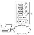
- FIG. 1 is a schematic view showing a configuration of a system according to the present embodiment.
- the system according to the present embodiment includes a scanner 3 and an information processing device 1 that are communicably connected to each other via a network or other communication means.
- the information processing device 1 includes a CPU (Central Processing Unit) 11, a ROM (Read Only Memory) 12, a RAM (Random Access Memory) 13, an EEPROM (Electrically Erasable and Program Memory) Memory Memory Memory, etc.
- a computer including a device 14, a communication unit 15, and the like.
- the information processing device 1 is shown as a computer having a single housing in the figure for simplification of the description, in the present embodiment, the information processing device 1 has a part or all of its functions as cloud technology. It may be executed by a device installed in a remote place or a plurality of devices installed in a distributed manner by using the above.
- the configuration of the information processing device 1 is not limited to the examples in the present embodiment.
- FIG. 2 is a diagram showing an outline of the hardware configuration of the scanner 3 according to the present embodiment.
- the scanner 3 is a device that acquires image data by capturing a document such as a document, a business card, a receipt, or a photograph / illustration set by a user, and is a sheet feeder (conveying unit) 36 that sends the document to the imaging unit 37.
- An image pickup device including an image pickup unit 37, a scan button 38, a CPU 31, a ROM 32, a RAM 33, a storage device 34, a communication unit 35, and the like.
- the scanner 3 according to the present embodiment employs, as an imaging method, an imaging method in which a document set in the sheet feeder 36 is automatically fed and imaged.
- the scanner 3 according to the present embodiment is a scanner having a function of connecting to a wireless LAN by having a wireless communication function. Further, the scanner 3 according to the present embodiment has a scan button 38 that the user presses or touches to instruct the scanner 3 to take an image. Further, the scanner 3 may further have a user interface for enabling character input / output and item selection, such as a touch panel display and a keyboard, and a Web browser function and a server function.
- the communication means and hardware configuration of the scanner that can adopt the method according to this embodiment are not limited to the examples in this embodiment.
- the program recorded in the storage device 34 is read into the RAM 33, executed by the CPU 31, and each hardware provided in the scanner 3 is controlled, so that the sheet feeder (conveying unit) 36 And the image pickup unit 37 are controlled.
- each function included in the scanner 3 is executed by the CPU 31, which is a general-purpose processor, but some or all of these functions may be executed by one or more dedicated processors.
- the scanner 3 acquires image data by taking an image while transporting the target. Specifically, when the operation of the scan button 38 is accepted, the scanner 3 according to the present embodiment controls the sheet feeder (conveying unit) 36 to send the original to the imaging unit 37 (the original is a protective sheet (carrier sheet). ), The original is sent to the image pickup unit 37 by transporting the carrier sheet), and the original (and the carrier sheet) is imaged to acquire image data. Further, the scanner 3 transmits the image data acquired by the imaging to the information processing device 1. The transmitted image data is acquired by the image acquisition unit 21 of the information processing device 1.
- pressing or touching the scan button 38 provided on the scanner 3 is accepted as a user operation for collectively instructing a series of processes from the start of scanning to the generation / output of an output image.
- the predetermined user operation that triggers the start of scanning is not limited to the examples in the present disclosure.
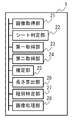
- FIG. 3 is a diagram showing an outline of the functional configuration of the information processing device 1 according to the present embodiment.
- the program recorded in the storage device 14 is read into the RAM 13 and executed by the CPU 11, and each hardware provided in the information processing device 1 is controlled to control the image acquisition unit. It functions as a device including 21, a sheet determination unit 22, a first acquisition unit 23, a second acquisition unit 24, an estimation unit 25, a length calculation unit 26, a type identification unit 27, and an image processing unit 28.
- each function included in the information processing device 1 is executed by the CPU 11 which is a general-purpose processor, but a part or all of these functions may be executed by one or more dedicated processors. ..
- the image acquisition unit 21 is a scanned image of the document and the carrier sheet obtained by taking an image while simultaneously transporting the document and a protective sheet (a so-called carrier sheet is used in the present embodiment) that protects the document. To get.
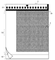
- FIG. 4 is a diagram showing a carrier sheet 5 used in the present embodiment and a manuscript 9 sandwiched between the carrier sheets 5.
- the carrier sheet 5 according to the present embodiment has a structure capable of sandwiching a document 9 (shaded portion in the drawing) between two films, and an upper end portion 51 set on the sheet feeder 36. In, the front and back films are adhered.
- the upper end portion 51 and the lower end portion 52 are colored on a white background, and the document setting portion 53 between the upper end portion 51 and the lower end portion 52 can image the document 9 sandwiched between the carrier sheets 5 from the outside of the carrier sheet 5.
- both the front film and the back film are transparent.
- the user opens the carrier sheet 5 from the lower end portion 52 and the document setting portion 53 (separates the front film and the back film), abuts the carrier sheet 5 at the adhesive position of the upper end portion 51, and closes the carrier sheet 5 (front film and back film).
- the document 9 is set in the document setting unit 53.
- the upper end portion 51 of the carrier sheet 5 has a mark on a white background for identifying the carrier sheet 5 (in the present embodiment, a plurality of black squares arranged at predetermined intervals in the direction orthogonal to the transport direction).
- the upper end portion 51 and / or the lower end portion 52 may be printed with guidance to the user such as how to use the carrier sheet 5.
- the specific specifications of the carrier sheet are not limited to the examples described in the present embodiment.
- the reference point 54 is used as a reference for the connection position at the time of front / back connection processing, which will be described later, or as a reference for the cutout position at the time of image cutting. Therefore, when the user sandwiches the document 9 for which the front and back connection processing is to be performed between the carrier sheets 5, or when he / she wants to cut out an image with a specified size, the document 9 is arranged so that the corners of the document 9 match the reference point 54. (See FIG. 4). However, the user does not need to align the corner of the document 9 with the reference point 54 when the front and back connection processing and the image cropping with the specified size are not performed.
- FIG. 5 is a diagram comparing the sizes of the actual carrier sheet 5 and the original 9 and the scanned image obtained by taking an image while transporting the carrier sheet 5 and the original 9 in the present embodiment.
- FIG. 5 shows how the actual length of the imaging target in the transport direction differs from the length of the imaging target in the captured image due to reasons such as the carrier sheet 5 slipping during transport.
- the first length A1 is the length in the transport direction of the predetermined portion of the carrier sheet 5 (in the present embodiment, the document setting portion 53 and the lower end portion 52), and the second length A2 is ,
- the length in the transport direction in the scanned image of a predetermined portion the document length B1 is the length in the transport direction of the document 9, and the document image length B2 is the length in the transport direction in the scanned image of the document 9.
- the document set section length C1 is the length in the transport direction of the document set section 53
- the document set section image length C2 is the length in the transport direction of the document set section 53 in the scanned image.
- the sheet determination unit 22 determines whether or not the scanned image includes the image of the carrier sheet 5. Further, the sheet determination unit 22 further determines the type of the carrier sheet 5 included in the scanned image. The specific determination method will be described later.
- the first acquisition unit 23 acquires the first length A1, which is the length of the predetermined portion of the carrier sheet 5 in the transport direction.
- the transport direction length used here it is preferable that the actual transport direction length is used, and specifically, the theoretical value (the length specified as the product specification of the carrier sheet 5) or the actual size is used. Be done.
- the original setting portion 53 and the lower end portion 52 of the carrier sheet 5 (the portion excluding the upper end portion 51 of the carrier sheet 5) are used as predetermined portions of the carrier sheet 5. That is, in the present embodiment, the first length A1 is the length in the transport direction of the document setting portion 53 and the lower end portion 52 (excluding the length in the transport direction of the upper end portion 51 from the length in the transport direction of the entire carrier sheet 5).
- Length is used (see FIG. 5).
- first length A1 the length of the other portion of the carrier sheet 5 in the transport direction may be used.
- the length of the document setting portion 53, the length of the upper end portion 51, the length of the lower end portion 52, the length of the entire carrier sheet 5, and the like can be used as the first length A1.
- the first acquisition unit 23 can acquire the first length A1 according to the type of the carrier sheet 5 determined by the sheet determination unit 22. The specific acquisition method will be described later.
- the second acquisition unit 24 acquires the second length A2, which is the length in the transport direction in the scanned image of the predetermined portion.
- the transport direction length A2 acquired here is the transport direction length of the image obtained by scanning, and may be different from the actual length A1 in the transport direction by being imaged while transporting.
- the calculation method of the second length A2 is not limited to this example.
- other information such as the actual transfer speed detected during the transfer and the pixel size may be used.
- the estimation unit 25 Based on the first length A1 and the second length A2, the estimation unit 25 has a document length B1 which is the length in the transport direction of the document 9 and a document which is the length in the transport direction in the scanned image of the document 9.
- the ratio to the image length B2 (B1: B2) is estimated.
- the length in the transport direction of the document 9 is specifically a theoretical value (a length predetermined for each document type. For example, if the document type is A4 standard, 297.0 mm) or the actual size.
- the estimation unit 25 determines the ratio of the first length A1 to the second length A2 (A1: A2) and the ratio of the document length B1 to the document image length B2 (B1: B2).
- the ratio (A1: A2) is calculated based on the first length A1 and the second length A2 obtained by the first acquisition unit 23 and the second acquisition unit 24.
- the calculated value is estimated as the ratio (B1: B2) of the document length B1 and the document image length B2.
- the estimated ratio does not have to be equal to the ratio (A1: A2) based on the first length A1 and the second length A2.
- the ratio (B1: B2) of the document length B1 to the document image length B2 may be estimated by multiplying the ratio (A1: A2) by some coefficient based on an empirical rule or the like.
- the expansion / contraction ratio (A2 / A1) is used as information for expressing the estimated ratio (B1: B2 or A1: A2).
- the length calculation unit 26 calculates the manuscript image length B2 for the predetermined manuscript type based on the manuscript length B1 for the predetermined manuscript type and the estimated ratio.
- the type identification unit 27 compares the original image length B2 for a predetermined original type calculated by the length calculation unit 26 with the length of the crop image cut out by the image processing unit 28, and thereby obtains the crop image. Identify the type of manuscript that fits.
- the image processing unit 28 cuts out a crop image from the scanned image before or after applying the correction based on the estimation ratio.
- various methods may be adopted as a specific image cutting method by the image processing unit 28.
- the image processing unit 28 may cut out a crop image by deleting a portion of the scanned image in which the content is not displayed (so-called content crop), or the original length from the scanned image after the correction is applied.
- a crop image may be cut out according to B1, or a crop image may be cut out from the scanned image before the correction is applied according to the original image length B2.
- the image processing unit 28 further executes front-back connection processing, output image generation processing, and the like, which will be described later.
- FIG. 6 is a flowchart showing the flow of carrier sheet image processing according to the present embodiment.
- the carrier sheet image processing according to the present embodiment is executed when the image data obtained by the image pickup unit 37 is acquired by the image acquisition unit 21.
- step S101 the scanned image is acquired.
- the image obtained by the image capturing unit 37 is an overscan image captured beyond the edge of the imaging target (carrier sheet 5 in the present embodiment). Therefore, the image acquisition unit 21 detects an edge from the so-called overscan image obtained from the image pickup unit 37 and cuts out the image at the edge, so that the upper end, the lower end, the left end, and the right end of the carrier sheet 5 are the upper end of the image. Acquire scanned images at the lower end, left end, and right end.
- the edge detection technique used here a conventional technique may be used, and thus the description thereof will be omitted. After that, the process proceeds to step S102.
- step S102 it is determined whether or not the scanned image includes the carrier sheet 5.
- the sheet determination unit 22 determines whether or not the upper end portion 51 of the scanned image has a predetermined mark (see FIG. 4) indicating that the scanned image is an image captured by using the carrier sheet 5. Then, it is determined whether the scanned image is an image of only the original or an image including the carrier sheet 5. If it is determined that the scanned image is an image of only the original, the process proceeds to step S103. On the other hand, if it is determined that the scanned image is an image including the carrier sheet 5, the process proceeds to step S104.
- step S103 normal document image processing is executed.
- the image processing unit 28 performs image processing on the general original image on the scanned image (original image). Since it is possible to use conventional techniques for image processing of a general original image, the description thereof will be omitted. After that, the process shown in this flowchart ends.
- step S104 the type of the carrier sheet 5 is determined.
- the sheet determination unit 22 determines the type of the carrier sheet 5 based on the scanned image. In the present embodiment, the sheet determination unit 22 determines in which preset range the length (height) of the scanned image in the transport direction and / or the length (width) in the direction orthogonal to the transport direction of the scanned image is. By determining, the type of the carrier sheet 5 is determined.
- the sheet determination unit 22 has an intermediate height. With 262.5 mm as the threshold, if the height of the scanned image is equal to or greater than the threshold, it is determined to be an A3 carrier sheet, and if the height of the scanned image is less than the threshold, it is determined to be a photographic carrier sheet.
- the type of the carrier sheet 5 can be determined. After that, the process proceeds to step S105.
- a mechanism for discriminating for example, a mark / shape / magnetic tape / IC chip for discriminating the type
- the sheet determination unit 22 may perform determination by extracting an image such as a type identification mark pre-printed on the carrier sheet 5 from the scanned image, or may perform determination when the carrier sheet 5 is conveyed / imaged.
- Some discriminating means mark / shape / magnetic tape / IC chip for discriminating, etc.
- Some discriminating means provided in advance on the carrier sheet 5 may be read by optical / mechanical / magnetic / electronic or other reading means. ..
- step S105 the expansion / contraction ratio (A2 / A1) of the scanned image generated by the image transport scan is calculated by executing the expansion / contraction ratio calculation process.
- the details of the expansion / contraction ratio calculation process will be described later with reference to FIG. After that, the process proceeds to step S106.
- step S106 the image of the document setting unit 53 is acquired.
- the image processing unit 28 further removes the lower end portion 52 of the carrier sheet 5 from the scanned image in which the upper end portion 51 has been removed by the expansion / contraction ratio calculation process.
- the lower end portion 52 does not have a band or a mark for specifying the removed portion. Therefore, the image processing unit 28 removes the lower end portion 52 of the carrier sheet 5 by cutting out an image having a size corresponding to the document setting unit 53 from the scanned image.
- the length calculation unit 26 acquires the document set unit length C1 which is the length in the transport direction of the document set unit 53 previously held in the storage device 14 according to the type of the carrier sheet, and obtains this.
- the image processing unit 28 removes the lower end portion 52 of the carrier sheet 5 from the scanned image by cutting out an image having a length C2 calculated from the upper end of the image. After that, the process proceeds to step S107.
- step S107 and step S108 front and back connection processing is executed as necessary.
- the image processing unit 28 confirms the setting contents recorded in the RAM 13 or the storage device 14, and the reading setting by the user performs double-sided scanning and connects the front surface scan result and the back surface scan result to 1. It is determined whether or not the processing for generating an image (hereinafter, referred to as “front and back connection processing”) is set (step S107).
- front and back connection processing the image processing unit 28 performs the front and back connection processing by connecting the front surface scan result and the back surface scan result according to the reference point 54 (see FIG. 4), and performs the front and back connection processing.
- a concatenated scan image is obtained (step S108).
- FIG. 7 is a diagram showing a front-back connected scan image in the present embodiment. According to FIG. 7, it can be seen that the front-back connected scan image is an image obtained by joining the front surface scan result and the back surface scan result according to the reference point 54. When the front-back connected scan image is obtained, the process proceeds to step S109.
- step S109 the output image generation process is executed. Details of the output image generation process will be described later with reference to FIG. After that, the process shown in this flowchart ends.
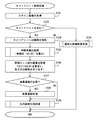
- FIG. 8 is a flowchart showing the flow of the expansion / contraction ratio calculation process according to the present embodiment.
- the expansion / contraction ratio calculation process according to the present embodiment corresponds to step S105 in the carrier sheet image processing described with reference to FIG.
- steps S201 and S202 the image of the upper end portion 51 is removed, and the length of the predetermined portion of the carrier sheet 5 on the image is calculated.
- the image processing unit 28 removes a portion corresponding to the upper end portion 51 of the carrier sheet 5 from the scanned image obtained in step S101 of the carrier sheet image processing (step S201). Specifically, the image processing unit 28 detects an L-shaped black band (see FIG. 4) for detecting the reference point 54 and the upper end portion 51 from the scanned image, thereby carrying the carrier in the scanned image. The upper end portion 51 of the sheet 5 is specified, and the specified portion is removed. Then, the second acquisition unit 24 calculates the second length A2, which is the length in the transport direction of the obtained image. Since the method of calculating the length from the image is as described above, the description thereof will be omitted (step S202). After that, the process proceeds to step S203.
- step S203 and step S204 the theoretical value of the length of the predetermined portion of the carrier sheet 5 is acquired, and the expansion / contraction ratio of the scanned image is calculated.
- the first acquisition unit 23 has a first length corresponding to the type of the carrier sheet 5 previously held in the storage device 14 according to the type of the carrier sheet 5 determined in step S104 of the carrier sheet image processing.
- Acquire A1 step S203.
- the estimation unit 25 calculates the ratio (A1: A2) of the first length A1 and the second length A2 (in this embodiment, the “stretch ratio of the scanned image (A2 / A1)”). (Step S204). After that, the process shown in this flowchart ends.
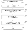
- FIG. 9 is a flowchart showing the flow of the output image generation process (1) according to the present embodiment.
- the output image generation process (1) according to the present embodiment corresponds to step S109 in the carrier sheet image processing described with reference to FIG.
- step S301 so-called content cropping is executed.
- the image processing unit 28 is a portion of the scanned image (a scanned image in which the upper end 51 and the lower end 52 of the carrier sheet 5 are removed in steps S201 and S106 so that only the document setting portion 53 is formed) in which no content is displayed.
- the part where the content is displayed hereinafter referred to as "cropped image" is cut out from the scanned image.
- the content crop technology used here the conventional technology may be used, and thus the description thereof will be omitted. After that, the process proceeds to step S302.
- step S302 the transport direction length for each document type is corrected, and the document image length B2 is calculated.
- the length calculation unit 26 corrects the original length B1 of the image (hereinafter, referred to as “canvas”) that serves as the mount on which the crop image acquired in step S301 is placed.
- canvas the original length B1 of the image
- A4 height 297.0 mm
- A5 height 210.0 mm
- A5 width height 148.0 mm
- A6 height 148.0 mm
- B5 the expansion / contraction ratio
- each of these standard heights (document length B1) is corrected by the expansion / contraction ratio (A2 / A1) of the scanned image calculated in step S204.
- step S303 the canvas is determined.
- the type identification unit 27 compares the height and width of the crop image obtained in step S301 with the height (original image length B2) and width of each canvas prepared in the canvas list. Determine the smallest canvas that can contain a crop image.
- the height corrected in step S302 is used as the height of the canvas to be compared. By doing so, even if the length (height) of the image in the transport direction differs from the actual length (height) of the image to be imaged in the transport direction due to the transport during scanning, an appropriate canvas can be obtained. It is possible to choose. After that, the process proceeds to step S304.
- step S304 an output image according to the size of the specified document type is generated.
- the image processing unit 28 generates an output image by pasting the crop image obtained in step S301 in the center of the canvas image (height B2) selected in step S303 after height correction in step S302. To do.
- the generated output image is output to the user as the final result of reading by the scanner and image processing by the information processing device 1, and is stored in the storage device 14. After that, the process shown in this flowchart ends.
- the canvas size or the cutout size is corrected without stretching and contracting the image itself, so that the image is stretched and captured during transportation.
- it has been decided to correspond it may be possible to correspond to the image taken by expanding and contracting during transportation by correcting the expansion and contraction of the image itself.
- the output image generation process in the case where the image itself is stretch-corrected to correspond to the image captured by stretching during transportation will be described.
- FIG. 10 is a diagram showing an outline of the functional configuration of the information processing device 1b according to the second embodiment.
- the information processing device 1b according to the present embodiment includes an image correction unit 29 in addition to the information processing device 1 described above with reference to FIG.
- the image correction unit 29 corrects the length of the scanned image or the length of the crop image cut out from the scanned image based on the estimation ratio.
- FIG. 11 is a flowchart showing the flow of the output image generation process (2) according to the second embodiment.
- the output image generation process (2) according to the present embodiment corresponds to step S109 in the carrier sheet image process described with reference to FIG.
- step S401 the size of the scanned image is stretch-corrected.
- the image correction unit 29 removes the upper end 51 and the lower end 52 of the carrier sheet 5 in the scanned images (steps S201 and S106) based on the expansion / contraction ratio (A2 / A1) of the scanned image calculated in step S204.
- A2 / A1 the expansion / contraction ratio of the scanned image calculated in step S204.
- step S402 content cropping is executed.
- the image processing unit 28 cuts out a portion (cropped image) in which the content is displayed from the scanned image by deleting the portion in the scanned image after applying the expansion / contraction correction in which the content is not displayed. After that, the process proceeds to step S403.
- step S401 and step S402 may be exchanged, and the crop image may be stretch-corrected.
- step S403 the canvas is determined.
- the type identification unit 27 compares the height and width of the crop image obtained in step S402 with the height and width of each canvas (original image length B1) and width prepared in the canvas list. Determine the smallest canvas that can contain a crop image.
- the height of the canvas to be compared is the original height that has not been corrected.
- the length (height) in the transport direction of the image is the length (height) in the transport direction of the actual imaging target due to the transport during scanning. It is possible to select an appropriate canvas even if it is different from. After that, the process proceeds to step S404.
- step S404 an output image according to the size of the specified document type is generated.
- the image processing unit 28 generates an output image by pasting the crop image obtained in step S402 at the center of the canvas image (height B1) selected in step S403.
- the generated output image is output to the user as the final result of reading by the scanner and image processing by the information processing device 1b, and is stored in the storage device 14. After that, the process shown in this flowchart ends.
- an example of adopting a content crop has been described as a method of cutting out a crop image from a scanned image, but other methods may be adopted as a method of cutting out a crop image.
- a method may be adopted in which a crop image of a specified size is cut out from the scanned image.
- the cutout range may be specified by edge detection of the document 9, or may be specified by using a reference point 54 at one vertex of the rectangle of the cutout range.
- an image of a specified size (for example, A3) is cut out centering on a reference point 54 (a point where the front and back images are joined). Can be done.
- the original length B1 of the size specified by the user is corrected by the expansion / contraction ratio (A2 / A1) of the scanned image, and the corrected height (original image length B2) can be used as the cutout size. Good.
Landscapes
- Engineering & Computer Science (AREA)
- Multimedia (AREA)
- Signal Processing (AREA)
- Facsimile Scanning Arrangements (AREA)
- Facsimiles In General (AREA)
- Editing Of Facsimile Originals (AREA)
Abstract
【課題】原稿が撮像部に搬送されながら撮像される種類の撮像装置において保護シートを用いた際に生じる、実際の原稿長さと原稿画像長さとの不一致を検知することを課題とする。 【解決手段】情報処理装置に、原稿及び保護シートが同時に搬送されながら撮像されることで得られたスキャン画像を取得する画像取得部と、保護シートの所定部分の搬送方向長さである第一の長さを取得する第一取得部と、所定部分のスキャン画像中の搬送方向長さである第二の長さを取得する第二取得部と、第一の長さ及び第二の長さに基づいて、原稿の搬送方向長さである原稿長さと原稿のスキャン画像中の搬送方向長さである原稿画像長さとの比を推定する推定部と、を備えた。
Description
本開示は、撮像によって得られた画像を処理するための技術に関する。
従来、予めフォーマットが決められた帳票のスキャン画像から文字認識を行う光学文字読取装置において、スキャナーによる帳票先端から読取位置までの寸法を検出し、帳票の寸法情報と位置検出部による帳票の実寸法を比較し、その比率に応じて各位置情報を補正することが提案されている(特許文献1を参照)。
また、画像読取データの副走査方向に沿う用紙左端および用紙右端の抽出を行い、抽出されたエッジに対してスキュー補正を施すとともに、補正された用紙左端の位置および用紙右端の位置とに基づく主走査方向の倍率補正を行うことが提案されている(特許文献2を参照)。
また、一定の間隔の白黒のマークが設けられた透明のキャリアシートに原稿を挟んで搬送してキャリアシートの白黒のマークを読み取り、基準と対比することで、読み取りデータを拡大、縮小又はそのまま蓄積する原稿移動型読み取り装置が提案されている(特許文献3を参照)。
従来、所謂ADF(Auto Document Feeder)スキャナー等の、原稿を撮像部に搬送しながら撮影するスキャナーが用いられており、このようなスキャナーでは、搬送機構による原稿搬送の際の原稿破損を防ぐ目的で、原稿を挟んだ状態で原稿と同時に撮像部に搬送される保護シート(キャリアシート)が用いられることがある。
しかし、保護シートを用いて原稿を搬送しながら撮像する場合、保護シートで原稿を挟むために一般的な原稿に比べて厚い、又は保護シートの摩擦係数が一般的な原稿の摩擦係数と異なる、等の理由により、搬送しながら撮像されたことで得られた画像の搬送方向長さが、実際の撮像対象の搬送方向長さと異なる、という問題が発生しうる。
本開示は、上記した問題に鑑み、原稿が撮像部に搬送されながら撮像される種類の撮像装置において保護シートを用いた際に生じる、実際の原稿長さと原稿画像長さとの不一致を検知することを課題とする。
本開示の一例は、原稿及び該原稿を保護する保護シートが同時に搬送されながら撮像されることで得られた、該原稿及び該保護シートのスキャン画像を取得する画像取得手段と、前記保護シートの所定部分の搬送方向長さである第一の長さを取得する第一取得手段と、前記所定部分の前記スキャン画像中の搬送方向長さである第二の長さを取得する第二取得手段と、前記第一の長さ及び前記第二の長さに基づいて、前記原稿の搬送方向長さである原稿長さと前記原稿の前記スキャン画像中の搬送方向長さである原稿画像長さとの比を推定する推定手段と、を備える情報処理装置である。
本開示は、情報処理装置、システム、コンピューターによって実行される方法またはコンピューターに実行させるプログラムとして把握することが可能である。また、本開示は、そのようなプログラムをコンピューターその他の装置、機械等が読み取り可能な記録媒体に記録したものとしても把握できる。ここで、コンピューター等が読み取り可能な記録媒体とは、データやプログラム等の情報を電気的、磁気的、光学的、機械的または化学的作用によって蓄積し、コンピューター等から読み取ることができる記録媒体をいう。
本開示によれば、原稿が撮像部に搬送されながら撮像される種類の撮像装置において保護シートを用いた際に生じる、実際の原稿長さと原稿画像長さとの不一致を検知することが可能となる。
以下、本開示に係る情報処理装置、方法およびプログラムの実施の形態を、図面に基づいて説明する。但し、以下に説明する実施の形態は、実施形態を例示するものであって、本開示に係る情報処理装置、方法およびプログラムを以下に説明する具体的構成に限定するものではない。実施にあたっては、実施の態様に応じた具体的構成が適宜採用され、また、種々の改良や変形が行われてよい。
本実施形態では、本開示に係る情報処理装置、方法およびプログラムを、スキャナーと連動するシステムとして実施した場合の実施の形態について説明する。但し、本開示に係る情報処理装置、方法およびプログラムは、撮像装置によって取得された画像データを処理するための技術について広く用いることが可能であり、本開示の適用対象は、本実施形態において示した例に限定されない。
<第一の実施形態>
図1は、本実施形態に係るシステムの構成を示す概略図である。本実施形態に係るシステムは、ネットワーク又はその他の通信手段を介して互いに通信可能に接続されたスキャナー3および情報処理装置1を備える。
図1は、本実施形態に係るシステムの構成を示す概略図である。本実施形態に係るシステムは、ネットワーク又はその他の通信手段を介して互いに通信可能に接続されたスキャナー3および情報処理装置1を備える。
情報処理装置1は、CPU(Central Processing Unit)11、ROM(Read Only Memory)12、RAM(Random Access Memory)13、EEPROM(Electrically Erasable and Programmable Read Only Memory)やHDD(Hard Disk Drive)等の記憶装置14、および通信ユニット15、等を備えるコンピューターである。なお、説明の簡略化のため、図では情報処理装置1を単一筐体のコンピューターとして示しているが、本実施形態において、情報処理装置1は、その機能の一部または全部が、クラウド技術等を用いて、遠隔地に設置された装置や、分散設置された複数の装置によって実行されてもよい。但し、情報処理装置1の構成は、本実施形態における例示に限定されない。
図2は、本実施形態に係るスキャナー3のハードウェア構成の概略を示す図である。スキャナー3は、ユーザーがセットした、文書、名刺、レシートまたは写真/イラスト等の原稿を撮像することで、画像データを取得する装置であり、原稿を撮像部37に送るシートフィーダー(搬送部)36、撮像部37、スキャンボタン38、CPU31、ROM32、RAM33、記憶装置34および通信ユニット35等を備える撮像装置である。なお、本実施形態に係るスキャナー3は、撮像方式として、シートフィーダー36にセットされた原稿を自動送りしながら撮像する撮像方式を採用している。
本実施形態に係るスキャナー3は、無線通信機能を備えることで無線LANに接続する機能を有したスキャナーである。また、本実施形態に係るスキャナー3は、スキャナー3に撮像を指示するためにユーザーが押下またはタッチするスキャンボタン38を有している。また、スキャナー3は、タッチパネルディスプレイやキーボード等の、文字入出力や項目選択を可能とするためのユーザーインターフェース、及びWebブラウザ機能やサーバー機能を更に有していてもよい。但し、本実施形態に係る方法を採用可能なスキャナーの通信手段およびハードウェア構成等は、本実施形態における例示に限定されない。
スキャナー3は、記憶装置34に記録されているプログラムが、RAM33に読み出され、CPU31によって実行されて、スキャナー3に備えられた各ハードウェアが制御されることで、シートフィーダー(搬送部)36及び撮像部37を制御する。なお、本実施形態では、スキャナー3の備える各機能は、汎用プロセッサであるCPU31によって実行されるが、これらの機能の一部または全部は、1または複数の専用プロセッサによって実行されてもよい。
スキャナー3は、所定のユーザー操作が受け付けられると、対象を搬送しながら撮像することによって画像データを取得する。具体的には、本実施形態に係るスキャナー3は、スキャンボタン38の操作が受け付けられると、シートフィーダー(搬送部)36を制御して原稿を撮像部37に送り(原稿が保護シート(キャリアシート)に挟まれている場合には、キャリアシートを搬送することで原稿を撮像部37に送り)、原稿(及びキャリアシート)を撮像することで、画像データを取得する。更に、スキャナー3は、撮像によって取得された画像データを、情報処理装置1に送信する。送信された画像データは、情報処理装置1の画像取得部21によって取得される。本実施形態では、スキャナー3に備えられたスキャンボタン38の押下またはタッチが、スキャン開始から出力画像の生成・出力までの一連の処理を一括して指示するためのユーザー操作として受け付けられる。但し、スキャン開始の契機となる所定のユーザー操作は、本開示における例示に限定されない。
図3は、本実施形態に係る情報処理装置1の機能構成の概略を示す図である。情報処理装置1は、記憶装置14に記録されているプログラムが、RAM13に読み出され、CPU11によって実行されて、情報処理装置1に備えられた各ハードウェアが制御されることで、画像取得部21、シート判定部22、第一取得部23、第二取得部24、推定部25、長さ算出部26、種別特定部27及び画像処理部28を備える装置として機能する。なお、本実施形態では、情報処理装置1の備える各機能は、汎用プロセッサであるCPU11によって実行されるが、これらの機能の一部または全部は、1または複数の専用プロセッサによって実行されてもよい。
画像取得部21は、原稿及び当該原稿を保護する保護シート(本実施形態では、所謂キャリアシートが用いられる)が同時に搬送されながら撮像されることで得られた、当該原稿及びキャリアシートのスキャン画像を取得する。
図4は、本実施形態で用いられるキャリアシート5及びキャリアシート5に挟まれた原稿9を示す図である。本実施形態に係るキャリアシート5は、2枚のフィルムの間に原稿9(図中の網掛け部分)を挟むことが可能な構造を有しており、シートフィーダー36にセットされる上端部51において、表裏のフィルムが接着されている。上端部51及び下端部52は白地に着色されており、上端部51と下端部52との間の原稿セット部53は、キャリアシート5に挟まれた原稿9をキャリアシート5の外から撮像可能なように、表フィルム及び裏フィルム共に透明である。ユーザーは、下端部52及び原稿セット部53からキャリアシート5を開き(表フィルムと裏フィルムとを分離し)、上端部51の接着位置に突合させ、キャリアシート5を閉じる(表フィルムと裏フィルムとを合わせる)ことで、原稿9を原稿セット部53にセットする。
また、キャリアシート5の上端部51には、白地に、キャリアシート5であることを識別するためのマーク(本実施形態では、搬送方向直交方向に所定の間隔で配置された複数の黒い四角)と、基準点54及び上端部51を検出するためのL字状の黒い帯(L字の頂点が基準点54である)と、シートフィーダー36へのセット方向(搬送方向)を示す矢印と、が印刷されている。また、図示は省略したが、上端部51及び/又は下端部52には、キャリアシート5の使用方法等のユーザーへの案内が印刷されていてもよい。但し、キャリアシートの具体的な仕様は、本実施形態で説明された例示に限定されない。
基準点54は、後述する表裏連結処理の際の連結位置の基準、又は画像切り出しの際の切り出し位置の基準とするために用いられる。このため、ユーザーは、表裏連結処理を行いたい原稿9をキャリアシート5に挟む場合や、指定サイズでの画像切り出しを行いたい場合には、原稿9の角が基準点54に合うように原稿9をセットする(図4を参照)。但し、表裏連結処理や指定サイズでの画像切り出しを行わない場合には、ユーザーは、原稿9の角を基準点54に合わせる必要はない。
図5は、本実施形態において、実際のキャリアシート5及び原稿9と、キャリアシート5及び原稿9を搬送しながら撮像することによって得られたスキャン画像とのサイズを対比する図である。図5は、搬送の際にキャリアシート5が滑る等の理由により、搬送方向における、撮像対象の実際の長さと、撮像された画像における撮像対象の長さとが異なってしまう様子を示している。詳細は後述するが、第一の長さA1は、キャリアシート5の所定部分(本実施形態では、原稿セット部53及び下端部52)の搬送方向長さであり、第二の長さA2は、所定部分のスキャン画像中の搬送方向長さであり、原稿長さB1は、原稿9の搬送方向長さであり、原稿画像長さB2は、原稿9のスキャン画像中の搬送方向長さであり、原稿セット部長さC1は、原稿セット部53の搬送方向長さであり、原稿セット部画像長さC2は、原稿セット部53のスキャン画像中の搬送方向長さである。
シート判定部22は、スキャン画像にキャリアシート5の画像が含まれるか否かを判定する。また、シート判定部22は、スキャン画像に含まれるキャリアシート5の種類を更に判定する。具体的な判定方法については後述する。
第一取得部23は、キャリアシート5の所定部分の搬送方向長さである第一の長さA1を取得する。ここで用いられる搬送方向長さには、実際の搬送方向長さが用いられることが好ましく、具体的には、理論値(キャリアシート5の製品仕様として規定されている長さ)又は実寸が用いられる。本実施形態では、キャリアシート5の所定部分として、キャリアシート5の原稿セット部53及び下端部52(キャリアシート5の上端部51を除いた部分)が用いられる。即ち、本実施形態において、第一の長さA1には、原稿セット部53及び下端部52の搬送方向長さ(キャリアシート5全体の搬送方向長さから上端部51の搬送方向長さを除いた長さ)が用いられる(図5を参照)。但し、第一の長さA1には、キャリアシート5のその他の部分の搬送方向長さが用いられてもよい。例えば、原稿セット部53の長さや、上端部51の長さ、下端部52の長さ、キャリアシート5全体の長さ、等を第一の長さA1として用いることが出来る。
なお、第一取得部23は、シート判定部22によって判定されたキャリアシート5の種類に応じた第一の長さA1を取得することが出来る。具体的な取得方法については後述する。
第二取得部24は、所定部分のスキャン画像中の搬送方向長さである第二の長さA2を取得する。ここで取得される搬送方向長さA2は、スキャンによって得られた画像の搬送方向長さであり、搬送しながら撮像されることにより、搬送方向における実際の長さA1と異なりうる。第二取得部24は、スキャン画像の単位長あたり画素数(例えば、dpi(dots per inch))及び搬送方向における画素数に基づいて、第二の長さA2を算出することが出来る(例えば、「画像の長さ(インチ)=画素数/dpi」)。但し、第二の長さA2の算出方法は、この例に限定されない。第二の長さA2の算出には、搬送の際に検出された実際の搬送速度や、画素のサイズ等、その他の情報が用いられてもよい。
推定部25は、第一の長さA1及び第二の長さA2に基づいて、原稿9の搬送方向長さである原稿長さB1と原稿9のスキャン画像中の搬送方向長さである原稿画像長さB2との比(B1:B2)を推定する。ここで、原稿9の搬送方向長さは、具体的には、理論値(原稿種別毎に予め決められた長さ。例えば、原稿種別がA4規格であれば297.0mm)又は実寸である。具体的には、推定部25は、第一の長さA1と第二の長さA2との比(A1:A2)と、原稿長さB1と原稿画像長さB2との比(B1:B2)とが同じであると推定し、第一取得部23及び第二取得部24によって得られた第一の長さA1及び第二の長さA2に基づいて比(A1:A2)を算出し、算出された値を原稿長さB1と原稿画像長さB2との比(B1:B2)と推定する。但し、推定される比は、第一の長さA1及び第二の長さA2に基づいて比(A1:A2)とイコールでなくてもよい。経験則等に基づいて、比(A1:A2)に何らかの係数がかけられることで、原稿長さB1と原稿画像長さB2との比(B1:B2)が推定されてもよい。なお、本実施形態では、推定比(B1:B2又はA1:A2)を表すための情報として、伸縮率(A2/A1)が用いられる。
長さ算出部26は、所定の原稿種別についての原稿長さB1及び推定比に基づいて、当該所定の原稿種別についての原稿画像長さB2を算出する。
種別特定部27は、長さ算出部26によって算出された所定の原稿種別についての原稿画像長さB2と、画像処理部28によって切り出されたクロップ画像の長さとを比較することで、当該クロップ画像が適合する原稿種別を特定する。
画像処理部28は、推定比に基づく補正の適用前又は適用後のスキャン画像からクロップ画像を切り出す。なお、画像処理部28による具体的な画像の切り出し方法には様々な手法が採用されてよい。例えば、画像処理部28は、スキャン画像におけるコンテンツが表示されていない部分を削除することで、クロップ画像を切り出してもよいし(所謂コンテンツクロップ)、補正の適用後のスキャン画像から、原稿長さB1に従ってクロップ画像を切り出しもよいし、補正の適用前のスキャン画像から、原稿画像長さB2に従ってクロップ画像を切り出してもよい。また、画像処理部28は、更に、後述する表裏連結処理や、出力画像の生成処理等を実行する。
次に、本実施形態に係る情報処理装置1によって実行される処理の流れを説明する。なお、以下に説明する処理の具体的な内容および処理順序は、本開示を実施するための一例である。具体的な処理内容および処理順序は、本開示の実施の形態に応じて適宜選択されてよい。
図6は、本実施形態に係るキャリアシート画像処理の流れを示すフローチャートである。本実施形態に係るキャリアシート画像処理は、撮像部37によって得られた画像データが画像取得部21によって取得されたことを契機として実行される。
ステップS101では、スキャン画像が取得される。本実施形態において、撮像部37が撮像することによって得られた画像は、撮像対象(本実施形態では、キャリアシート5)の端を超えて撮像されたオーバースキャン画像である。このため、画像取得部21は、撮像部37から得た所謂オーバースキャン画像からエッジを検出し、エッジで画像切り出しを行うことで、キャリアシート5の上端、下端、左端及び右端が画像の上端、下端、左端及び右端となるスキャン画像を取得する。ここで用いられるエッジ検出技術については、従来の技術が用いられてよいため、説明を省略する。その後、処理はステップS102へ進む。
ステップS102では、スキャン画像がキャリアシート5を含むか否かが判定される。シート判定部22は、スキャン画像の上端部51に、スキャン画像がキャリアシート5を用いて撮像された画像であることを示す所定のマーク(図4を参照)があるか否かを判定することで、スキャン画像が原稿のみの画像であるか、又はキャリアシート5を含む画像であるか、を判定する。スキャン画像が原稿のみの画像であると判定された場合、処理はステップS103へ進む。一方、スキャン画像がキャリアシート5を含む画像であると判定された場合、処理はステップS104へ進む。
ステップS103では、通常の原稿画像処理が実行される。スキャン画像が原稿のみの画像であると判定された場合、画像処理部28は、スキャン画像(原稿画像)について、一般的な原稿画像についての画像処理を施す。一般的な原稿画像についての画像処理については、従来の技術を用いることが可能であるため、説明を省略する。その後、本フローチャートに示された処理は終了する。
ステップS104では、キャリアシート5の種類が判別される。スキャン画像がキャリアシート5を含む画像であると判定された場合、シート判定部22は、スキャン画像に基づいて、キャリアシート5の種類を判別する。本実施形態では、シート判定部22は、スキャン画像の搬送方向長さ(高さ)及び/又はスキャン画像の搬送方向直交方向長さ(幅)が、予め設定された何れの範囲にあるかを判定することで、キャリアシート5の種類を判別する。
例えば、キャリアシート5が2種類存在し、1つがA3キャリアシート(A3サイズの原稿を折りたたんでA4相当のサイズにしてキャリアシートに挟み込み、両面スキャン結果を繋ぎ合わせる表裏連結処理を行うことでA3原稿全体の画像を得るための高さ355mmのキャリアシート)であり、1つが写真キャリアシート(写真を保護するための高さ170mmのキャリアシート)である場合、シート判定部22は、その中間の高さである262.5mmを閾値として、スキャン画像の高さが閾値以上である場合にはA3キャリアシートと判定し、スキャン画像の高さが閾値未満である場合には写真キャリアシートと判定する。このような判別手段によれば、キャリアシート5側に判別のための仕組み(例えば、種類判別用のマーク/形状/磁気テープ/ICチップ等)が備えられていない場合でも、キャリアシート5の種類を判別することが出来る。その後、処理はステップS105へ進む。
但し、キャリアシート5の種類を判別する方法には、その他の方法が採用されてもよい。シート判定部22は、スキャン画像から、キャリアシート5に予め印刷されていた種類判別用のマーク等の画像を抽出することで判別を行なってもよいし、キャリアシート5の搬送/撮像の際に、キャリアシート5に予め備えられた何らかの判別手段(判別用のマーク/形状/磁気テープ/ICチップ等)を、光学的/機械的/磁気的/電子的その他の読取手段で読み取ることとしてもよい。
ステップS105では、伸縮率算出処理が実行されることで、画像の搬送スキャンによって生じた、スキャン画像の伸縮率(A2/A1)が算出される。伸縮率算出処理の詳細については、図8を参照して後述する。その後、処理はステップS106へ進む。
ステップS106では、原稿セット部53の画像が取得される。画像処理部28は、伸縮率算出処理によって上端部51を除去済みのスキャン画像から、更にキャリアシート5の下端部52を除去する。但し、本実施形態において用いるキャリアシート5では、下端部52には除去部分を特定するための帯やマークが無い。このため、画像処理部28は、スキャン画像から、原稿セット部53に相当するサイズの画像を切り出すことで、キャリアシート5の下端部52を除去する。具体的には、長さ算出部26は、キャリアシートの種類に応じて予め記憶装置14に保持されている原稿セット部53の搬送方向長さである原稿セット部長さC1を取得し、これを伸縮率(A2/A1)を用いて補正することで、原稿セット部53のスキャン画像中の搬送方向長さである原稿セット部画像長さC2(C2=C1*A2/A1)を算出する(図5を参照)。そして、画像処理部28は、画像の上端から算出された長さC2だけの画像を切り出すことで、スキャン画像からキャリアシート5の下端部52を除去する。その後、処理はステップS107へ進む。
ステップS107及びステップS108では、必要に応じて、表裏連結処理が実行される。画像処理部28は、RAM13又は記憶装置14に記録された設定内容を確認することで、ユーザーによる読み取り設定が、両面スキャンを行なって表面のスキャン結果と裏面のスキャン結果とを繋ぎ合わせて1の画像を生成する処理(以下、「表裏連結処理」と称する)の設定であるか否かを判定する(ステップS107)。ユーザーによって表裏連結が設定されていた場合、画像処理部28は、表面のスキャン結果と裏面のスキャン結果とを基準点54(図4を参照)に従って繋ぎ合わせることで、表裏連結処理を行い、表裏連結スキャン画像を得る(ステップS108)。
図7は、本実施形態における表裏連結スキャン画像を示す図である。図7によれば、表裏連結スキャン画像が、表面のスキャン結果と裏面のスキャン結果とを基準点54に従って繋ぎ合わせることで得られた画像であることが分かる。表裏連結スキャン画像が得られると、処理はステップS109へ進む。
ステップS109では、出力画像生成処理が実行される。出力画像生成処理の詳細については、図9を参照して後述する。その後、本フローチャートに示された処理は終了する。
図8は、本実施形態に係る伸縮率算出処理の流れを示すフローチャートである。本実施形態に係る伸縮率算出処理は、図6を用いて説明したキャリアシート画像処理におけるステップS105に相当する。
ステップS201及びステップS202では、上端部51の画像が除去され、キャリアシート5の所定部分の画像上の長さが算出される。画像処理部28は、キャリアシート画像処理のステップS101で得られたスキャン画像から、キャリアシート5の上端部51に相当する部分を除去する(ステップS201)。具体的には、画像処理部28は、スキャン画像から、基準点54及び上端部51を検出するためのL字状の黒い帯(図4を参照)を検出することで、スキャン画像中のキャリアシート5の上端部51を特定し、特定された部分を除去する。そして、第二取得部24は、得られた画像の搬送方向長さである第二の長さA2を算出する。画像から長さを算出する方法については、上記説明した通りであるため、説明を省略する(ステップS202)。その後、処理はステップS203へ進む。
ステップS203及びステップS204では、キャリアシート5の所定部分の長さの理論値が取得され、スキャン画像の伸縮率が算出される。第一取得部23は、キャリアシート画像処理のステップS104で判別されたキャリアシート5の種類に応じて、記憶装置14に予め保持されている、キャリアシート5の種類に対応する第一の長さA1を取得する(ステップS203)。そして、推定部25は、第一の長さA1と第二の長さA2との比(A1:A2)(本実施形態では、「スキャン画像の伸縮率(A2/A1)」)を算出する(ステップS204)。その後、本フローチャートに示された処理は終了する。
図9は、本実施形態に係る出力画像生成処理(1)の流れを示すフローチャートである。本実施形態に係る出力画像生成処理(1)は、図6を用いて説明したキャリアシート画像処理におけるステップS109に相当する。
ステップS301では、所謂コンテンツクロップが実行される。画像処理部28は、スキャン画像(ステップS201及びステップS106でキャリアシート5の上端部51及び下端部52が除去され、原稿セット部53のみとなったスキャン画像)における、コンテンツが表示されていない部分を削除することで、スキャン画像から、コンテンツが表示されている部分(以下、「クロップ画像」と称する)を切り出す。ここで用いられるコンテンツクロップ技術については、従来の技術が用いられてよいため、説明を省略する。その後、処理はステップS302へ進む。
ステップS302では、原稿種別毎の搬送方向長さが補正され、原稿画像長さB2が算出される。長さ算出部26は、ステップS301で取得されたクロップ画像が配置される台紙となる画像(以下、「キャンバス」と称する)の原稿長さB1を補正する。例えば、予め提供されているキャンバスのリストに、A4(高さ297.0mm)、A5(高さ210.0mm)、A5横(高さ148.0mm)、A6(高さ148.0mm)及びB5(高さ257.0mm)が用意されている場合、これらの規格の高さ(原稿長さB1)の夫々を、ステップS204で算出されたスキャン画像の伸縮率(A2/A1)で補正し、補正後の高さ(原稿画像長さB2)(B2=B1*A2/A1)を算出する(図5を参照)。その後、処理はステップS303へ進む。
ステップS303では、キャンバスが決定される。種別特定部27は、ステップS301で得られたクロップ画像の高さ及び幅と、キャンバスのリストに用意されている各キャンバスの高さ(原稿画像長さB2)及び幅とを比較することで、クロップ画像を包含可能な最小サイズのキャンバスを決定する。この際、比較されるキャンバスの高さには、ステップS302で補正された高さが用いられる。このようにすることで、スキャンの際の搬送によって画像の搬送方向長さ(高さ)が実際の撮像対象の搬送方向長さ(高さ)と異なってしまった場合にも、適切なキャンバスを選択することが可能である。その後、処理はステップS304へ進む。
ステップS304では、特定された原稿種別のサイズに従った出力画像が生成される。画像処理部28は、ステップS301で得られたクロップ画像を、ステップS302で高さ補正され、ステップS303で選択されたキャンバスの画像(高さB2)の中央に貼り付けることで、出力画像を生成する。生成された出力画像は、スキャナーによる読み取り及び情報処理装置1による画像処理の最終結果として、ユーザーに対して出力され、記憶装置14に保存される。その後、本フローチャートに示された処理は終了する。
<第二の実施形態>
また、図9を用いて説明した出力画像生成処理(1)では、画像自体を伸縮補正することなく、キャンバスサイズ又は切り出しサイズを補正することで、搬送の際に伸縮して撮像された画像に対応することとしたが、画像自体を伸縮補正することで、搬送の際に伸縮して撮像された画像に対応することとしてもよい。以下、画像自体を伸縮補正することで、搬送の際に伸縮して撮像された画像に対応する場合の出力画像生成処理について説明する。
また、図9を用いて説明した出力画像生成処理(1)では、画像自体を伸縮補正することなく、キャンバスサイズ又は切り出しサイズを補正することで、搬送の際に伸縮して撮像された画像に対応することとしたが、画像自体を伸縮補正することで、搬送の際に伸縮して撮像された画像に対応することとしてもよい。以下、画像自体を伸縮補正することで、搬送の際に伸縮して撮像された画像に対応する場合の出力画像生成処理について説明する。
図10は、第二の実施形態に係る情報処理装置1bの機能構成の概略を示す図である。本実施形態に係る情報処理装置1bは、図3を用いて上記で説明した情報処理装置1に加えて、画像補正部29を備える。
画像補正部29は、推定比に基づいて、スキャン画像の長さ又は当該スキャン画像から切り出されたクロップ画像の長さを補正する。
次に、第二の実施形態に係る情報処理装置1bによって実行される処理の流れを説明する。図6及び図8を参照して説明したキャリアシート画像処理及び伸縮率算出処理については、上記説明した実施形態と同様であるため、説明を省略し、図9を参照して説明した出力画像生成処理(1)に代えて実行される出力画像生成処理(2)のみ説明する。なお、以下に説明する処理の具体的な内容および処理順序は、本開示を実施するための一例である。具体的な処理内容および処理順序は、本開示の実施の形態に応じて適宜選択されてよい。
図11は、第二の実施形態に係る出力画像生成処理(2)の流れを示すフローチャートである。本実施形態に係る出力画像生成処理(2)は、図6を用いて説明したキャリアシート画像処理におけるステップS109に相当する。
ステップS401では、スキャン画像のサイズが伸縮補正される。画像補正部29は、ステップS204で算出されたスキャン画像の伸縮率(A2/A1)に基づいて、スキャン画像(ステップS201及びステップS106でキャリアシート5の上端部51及び下端部52が除去され、原稿セット部53のみとなったスキャン画像)の搬送方向長さを伸縮することで、実際の読み取り対象の搬送方向長さと推測される長さに、スキャン画像自体の長さを補正(具体的には、搬送方向においてA1/A2倍に画像を伸縮)する。画像の伸縮補正に際しては、画素の補完又は間引きが必要となるが、画像の伸縮補正については従来技術が用いられてよいため、詳細な説明は省略する。その後、処理はステップS402へ進む。
ステップS402では、コンテンツクロップが実行される。画像処理部28は、伸縮補正の適用後のスキャン画像における、コンテンツが表示されていない部分を削除することで、スキャン画像から、コンテンツが表示されている部分(クロップ画像)を切り出す。その後、処理はステップS403へ進む。
なお、本実施形態では、スキャン画像からキャリアシート5の上端部51及び下端部52が除去された後、且つクロップ画像の取得前のタイミングで画像の伸縮補正が行われる例について説明したが、画像の伸縮補正が行われるタイミングは、画像の伸縮率が判明した後であれば、何れの段階で行われてもよい。例えば、ステップS401とステップS402との処理順序を入れ替え、クロップ画像に対して伸縮補正が行われてもよい。
ステップS403では、キャンバスが決定される。種別特定部27は、ステップS402で得られたクロップ画像の高さ及び幅と、キャンバスのリストに用意されている各キャンバスの高さ(原稿画像長さB1)及び幅とを比較することで、クロップ画像を包含可能な最小サイズのキャンバスを決定する。この際、比較されるキャンバスの高さは、第一の実施形態と異なり、補正されていないオリジナルの高さが用いられる。本実施形態では、ステップS401において画像の長さが伸縮補正済みであるため、スキャンの際の搬送によって画像の搬送方向長さ(高さ)が実際の撮像対象の搬送方向長さ(高さ)と異なってしまった場合にも、適切なキャンバスを選択することが可能である。その後、処理はステップS404へ進む。
ステップS404では、特定された原稿種別のサイズに従った出力画像が生成される。画像処理部28は、ステップS402で得られたクロップ画像を、ステップS403で選択されたキャンバスの画像(高さB1)の中央に貼り付けることで、出力画像を生成する。生成された出力画像は、スキャナーによる読み取り及び情報処理装置1bによる画像処理の最終結果として、ユーザーに対して出力され、記憶装置14に保存される。その後、本フローチャートに示された処理は終了する。
<その他のバリエーション>
なお、上記説明した実施形態では、コンテンツクロップされたクロップ画像を、クロップ画像のサイズに適したキャンバスに貼り付けることで最終的な出力画像を生成する実施形態について説明したが、出力画像には、その他の方法で生成された画像が採用されてよい。例えば、クロップ画像がそのまま出力画像とされてもよいし、クロップ画像が貼り付けられるキャンバスのサイズが、ユーザーによって指定されたサイズであってもよい。
なお、上記説明した実施形態では、コンテンツクロップされたクロップ画像を、クロップ画像のサイズに適したキャンバスに貼り付けることで最終的な出力画像を生成する実施形態について説明したが、出力画像には、その他の方法で生成された画像が採用されてよい。例えば、クロップ画像がそのまま出力画像とされてもよいし、クロップ画像が貼り付けられるキャンバスのサイズが、ユーザーによって指定されたサイズであってもよい。
また、上記説明した実施形態では、スキャン画像からクロップ画像を切り出す方法について、コンテンツクロップを採用した例について説明したが、クロップ画像を切り出す方法には、その他の方法が採用されてよい。例えば、スキャン画像から、指定されたサイズのクロップ画像が切り出される方式が採用されてもよい。この際、切り出し範囲は、原稿9のエッジ検出によって特定されてもよいし、切り出し範囲の矩形の1つの頂点に基準点54を用いて特定されてもよい。
また、表裏連結スキャン画像(図7を参照)からクロップ画像を得る場合には、基準点54(表裏の画像を繋ぎ合わせた点)を中心として、規定サイズ(例えば、A3)分の画像を切り出すことが出来る。
更に、切り出しサイズについては、ユーザーによって指定されたサイズの原稿長さB1をスキャン画像の伸縮率(A2/A1)で補正し、補正後の高さ(原稿画像長さB2)を切り出しサイズとしてもよい。
また、上記説明した実施形態では、スキャナーによって撮像された画像が情報処理装置1に送られ、情報処理装置1がキャリアシート画像処理、伸縮率算出処理及び出力画像生成処理等を実行する例について説明したが、上記説明した実施形態において情報処理装置1が備える機能の一部又は全部は、スキャナー3に内蔵され、スキャナー側で処理されてもよい。
1 情報処理装置
3 スキャナー
3 スキャナー
Claims (14)
- 原稿及び該原稿を保護する保護シートが同時に搬送されながら撮像されることで得られた、該原稿及び該保護シートのスキャン画像を取得する画像取得手段と、
前記保護シートの所定部分の搬送方向長さである第一の長さを取得する第一取得手段と、
前記所定部分の前記スキャン画像中の搬送方向長さである第二の長さを取得する第二取得手段と、
前記第一の長さ及び前記第二の長さに基づいて、前記原稿の搬送方向長さである原稿長さと前記原稿の前記スキャン画像中の搬送方向長さである原稿画像長さとの比を推定する推定手段と、
を備える情報処理装置。 - 前記スキャン画像から前記クロップ画像を切り出す画像処理手段を更に備える、
請求項1に記載の情報処理装置。 - 前記画像処理手段は、前記スキャン画像におけるコンテンツが表示されていない部分を削除することで、前記クロップ画像を切り出す、
請求項2に記載の情報処理装置。 - 前記画像処理手段は、前記推定手段によって推定された前記比に基づく補正の適用前又は適用後のスキャン画像から前記クロップ画像を切り出す、
請求項2又は3に記載の情報処理装置。 - 前記画像処理手段は、前記補正の適用後のスキャン画像から、前記原稿長さに従って前記クロップ画像を切り出す、
請求項4に記載の情報処理装置。 - 前記画像処理手段は、前記補正の適用前のスキャン画像から、前記原稿画像長さに従って前記クロップ画像を切り出す、
請求項4に記載の情報処理装置。 - 前記推定手段によって推定された前記比に基づいて、前記スキャン画像の長さ又は該スキャン画像から切り出されたクロップ画像の長さを補正する画像補正手段を更に備える、
請求項1から6の何れか一項に記載の情報処理装置。 - 所定の原稿種別についての原稿長さ及び前記比に基づいて、該所定の原稿種別についての原稿画像長さを算出する長さ算出手段を更に備える、
請求項1から7の何れか一項に記載の情報処理装置。 - 前記長さ算出手段によって算出された前記所定の原稿種別についての原稿画像長さと、前記画像処理手段によって切り出された前記クロップ画像の長さとを比較することで、該クロップ画像が適合する原稿種別を特定する、種別特定手段を更に備える、
請求項8に記載の情報処理装置。 - 前記スキャン画像に前記保護シートの画像が含まれるか否かを判定するシート判定手段を更に備える、
請求項1から9の何れか一項に記載の情報処理装置。 - 前記シート判定手段は、前記スキャン画像に含まれる前記保護シートの種類を更に判定し、
前記第一取得手段は、前記保護シートの種類に応じた前記第一の長さを取得する、
請求項10に記載の情報処理装置。 - 前記原稿及び前記保護シートを同時に搬送可能な搬送手段と、
前記搬送手段によって搬送された対象を撮像する撮像手段と、
を更に備える、請求項1から11の何れか一項に記載の情報処理装置。 - コンピューターが、
原稿及び該原稿を保護する保護シートが同時に搬送されながら撮像されることで得られた、該原稿及び該保護シートのスキャン画像を取得する画像取得ステップと、
前記保護シートの所定部分の搬送方向長さである第一の長さを取得する第一取得ステップと、
前記所定部分の前記スキャン画像中の搬送方向長さである第二の長さを取得する第二取得ステップと、
前記第一の長さ及び前記第二の長さに基づいて、前記原稿の搬送方向長さである原稿長さと前記原稿の前記スキャン画像中の搬送方向長さである原稿画像長さとの比を推定する推定ステップと、
を実行する方法。 - コンピューターを、
原稿及び該原稿を保護する保護シートが同時に搬送されながら撮像されることで得られた、該原稿及び該保護シートのスキャン画像を取得する画像取得手段と、
前記保護シートの所定部分の搬送方向長さである第一の長さを取得する第一取得手段と、
前記所定部分の前記スキャン画像中の搬送方向長さである第二の長さを取得する第二取得手段と、
前記第一の長さ及び前記第二の長さに基づいて、前記原稿の搬送方向長さである原稿長さと前記原稿の前記スキャン画像中の搬送方向長さである原稿画像長さとの比を推定する推定手段と、
として機能させるためのプログラム。
Priority Applications (3)
| Application Number | Priority Date | Filing Date | Title |
|---|---|---|---|
| PCT/JP2019/011351 WO2020188729A1 (ja) | 2019-03-19 | 2019-03-19 | 情報処理装置、方法及びプログラム |
| JP2021506876A JP7199511B2 (ja) | 2019-03-19 | 2019-03-19 | 情報処理装置、方法及びプログラム |
| US17/475,546 US11729328B2 (en) | 2019-03-19 | 2019-03-19 | Information processing device, method, and a non-transitory computer readable storage medium for scanning an image using a protective sheet to estimate a ratio of document lengths, acquired from scanned images, to correct a length of a scanned image or length of a cropped image, based on the ratio |
Applications Claiming Priority (1)
| Application Number | Priority Date | Filing Date | Title |
|---|---|---|---|
| PCT/JP2019/011351 WO2020188729A1 (ja) | 2019-03-19 | 2019-03-19 | 情報処理装置、方法及びプログラム |
Publications (1)
| Publication Number | Publication Date |
|---|---|
| WO2020188729A1 true WO2020188729A1 (ja) | 2020-09-24 |
Family
ID=72519728
Family Applications (1)
| Application Number | Title | Priority Date | Filing Date |
|---|---|---|---|
| PCT/JP2019/011351 Ceased WO2020188729A1 (ja) | 2019-03-19 | 2019-03-19 | 情報処理装置、方法及びプログラム |
Country Status (3)
| Country | Link |
|---|---|
| US (1) | US11729328B2 (ja) |
| JP (1) | JP7199511B2 (ja) |
| WO (1) | WO2020188729A1 (ja) |
Families Citing this family (2)
| Publication number | Priority date | Publication date | Assignee | Title |
|---|---|---|---|---|
| JP7825982B2 (ja) * | 2021-12-08 | 2026-03-09 | キヤノン株式会社 | 画像読取装置 |
| JP2023098014A (ja) * | 2021-12-28 | 2023-07-10 | セイコーエプソン株式会社 | 画像読取システム、画像読取方法及びプログラム、画像読取装置 |
Citations (4)
| Publication number | Priority date | Publication date | Assignee | Title |
|---|---|---|---|---|
| JPH07129706A (ja) * | 1993-10-28 | 1995-05-19 | Nippon Telegr & Teleph Corp <Ntt> | 文字認識処理方法と文字認識処理装置及びそれに用いるマークシート |
| JPH09270907A (ja) * | 1996-03-29 | 1997-10-14 | Nec Eng Ltd | 原稿移動型読み取り装置 |
| JPH1095544A (ja) * | 1996-09-25 | 1998-04-14 | Canon Inc | キャリアシートおよび画像読取装置 |
| JP2003338920A (ja) * | 2002-05-21 | 2003-11-28 | Canon Inc | 画像読取装置 |
Family Cites Families (6)
| Publication number | Priority date | Publication date | Assignee | Title |
|---|---|---|---|---|
| JPH06274683A (ja) | 1993-03-19 | 1994-09-30 | Fujitsu Ltd | 光学文字読取装置 |
| JP4480291B2 (ja) * | 2000-12-14 | 2010-06-16 | 株式会社リコー | 画像歪み補正装置、記憶媒体、プログラム、画像歪み補正方法、画像読取装置および画像形成装置 |
| JP2006166180A (ja) * | 2004-12-09 | 2006-06-22 | Noritsu Koki Co Ltd | 写真処理装置 |
| JP2007110521A (ja) * | 2005-10-14 | 2007-04-26 | Canon Inc | 画像読み取り方法、画像読み取り装置及び制御装置 |
| JP5822664B2 (ja) * | 2011-11-11 | 2015-11-24 | 株式会社Pfu | 画像処理装置、直線検出方法及びコンピュータプログラム |
| JP6171817B2 (ja) | 2013-10-04 | 2017-08-02 | 富士ゼロックス株式会社 | 画像読取装置および画像形成装置 |
-
2019
- 2019-03-19 JP JP2021506876A patent/JP7199511B2/ja active Active
- 2019-03-19 US US17/475,546 patent/US11729328B2/en active Active
- 2019-03-19 WO PCT/JP2019/011351 patent/WO2020188729A1/ja not_active Ceased
Patent Citations (4)
| Publication number | Priority date | Publication date | Assignee | Title |
|---|---|---|---|---|
| JPH07129706A (ja) * | 1993-10-28 | 1995-05-19 | Nippon Telegr & Teleph Corp <Ntt> | 文字認識処理方法と文字認識処理装置及びそれに用いるマークシート |
| JPH09270907A (ja) * | 1996-03-29 | 1997-10-14 | Nec Eng Ltd | 原稿移動型読み取り装置 |
| JPH1095544A (ja) * | 1996-09-25 | 1998-04-14 | Canon Inc | キャリアシートおよび画像読取装置 |
| JP2003338920A (ja) * | 2002-05-21 | 2003-11-28 | Canon Inc | 画像読取装置 |
Also Published As
| Publication number | Publication date |
|---|---|
| JPWO2020188729A1 (ja) | 2021-11-18 |
| US11729328B2 (en) | 2023-08-15 |
| US20220311891A1 (en) | 2022-09-29 |
| JP7199511B2 (ja) | 2023-01-05 |
Similar Documents
| Publication | Publication Date | Title |
|---|---|---|
| JP4057545B2 (ja) | 画像処理装置及び方法 | |
| US9926156B2 (en) | Sheet size specification system, sheet size specification method, computer-readable storage medium storing sheet size specification program, and image forming device | |
| TWI513271B (zh) | 用於掃描多頁文件之掃描系統及方法 | |
| US9531897B2 (en) | Scanner and scanning method | |
| JPWO2018008067A1 (ja) | 画像読取装置、制御方法及び制御プログラム | |
| JP7199511B2 (ja) | 情報処理装置、方法及びプログラム | |
| US9143653B2 (en) | Image processing apparatus, method, and computer program product identifying show-through position based on back side image and expanded front side image | |
| JP2013157966A (ja) | 画像読取装置 | |
| US8879129B2 (en) | Method of capturing an image of a document | |
| US10819875B2 (en) | Image reading apparatus | |
| US11363153B2 (en) | Medium conveying apparatus for determining whether a conveyed medium is ID card | |
| US9270838B2 (en) | Verifying accuracy of a scanned document | |
| JP5383296B2 (ja) | 画像読取装置及び方法、並びにプログラム | |
| US10084938B2 (en) | Reading apparatus and non-transitory storage medium storing instructions executable by reading apparatus | |
| JP2020155962A (ja) | 画像読取装置、画像処理システム、制御方法及び制御プログラム | |
| US11979540B2 (en) | Image reading system, image reading method, non-transitory computer-readable storage medium for correcting a size and position of an image to be displayed | |
| US10334132B2 (en) | Image reading device for rotating read image in accordance with orientation of face image, image forming apparatus, and image reading method | |
| US20150201097A1 (en) | Scanning apparatus | |
| US20230398776A1 (en) | Inspection apparatus, inspection method, and storage medium | |
| JP2020123796A (ja) | 画像読取装置、画像読取装置の制御方法、及びプログラム | |
| US8879130B2 (en) | System for capturing an image of a document | |
| JP7141973B2 (ja) | 画像読取装置、画像処理システム、制御方法及び制御プログラム | |
| JP2016163142A (ja) | プログラム及び画像処理装置 | |
| JPH09305708A (ja) | 光学式文字読み取り装置における間延びデータ補正方法 | |
| JP2017092778A (ja) | 画像読取装置、複写装置、及びその読取方法 |
Legal Events
| Date | Code | Title | Description |
|---|---|---|---|
| 121 | Ep: the epo has been informed by wipo that ep was designated in this application |
Ref document number: 19920130 Country of ref document: EP Kind code of ref document: A1 |
|
| ENP | Entry into the national phase |
Ref document number: 2021506876 Country of ref document: JP Kind code of ref document: A |
|
| NENP | Non-entry into the national phase |
Ref country code: DE |
|
| 122 | Ep: pct application non-entry in european phase |
Ref document number: 19920130 Country of ref document: EP Kind code of ref document: A1 |