WO2020184117A1 - 姿勢改善支援装置、姿勢改善支援方法、及び姿勢改善支援プログラム - Google Patents
姿勢改善支援装置、姿勢改善支援方法、及び姿勢改善支援プログラム Download PDFInfo
- Publication number
- WO2020184117A1 WO2020184117A1 PCT/JP2020/006645 JP2020006645W WO2020184117A1 WO 2020184117 A1 WO2020184117 A1 WO 2020184117A1 JP 2020006645 W JP2020006645 W JP 2020006645W WO 2020184117 A1 WO2020184117 A1 WO 2020184117A1
- Authority
- WO
- WIPO (PCT)
- Prior art keywords
- posture
- display
- condition
- sound
- improvement support
- Prior art date
- Legal status (The legal status is an assumption and is not a legal conclusion. Google has not performed a legal analysis and makes no representation as to the accuracy of the status listed.)
- Ceased
Links
Images

Classifications
-
- A—HUMAN NECESSITIES
- A61—MEDICAL OR VETERINARY SCIENCE; HYGIENE
- A61B—DIAGNOSIS; SURGERY; IDENTIFICATION
- A61B5/00—Measuring for diagnostic purposes; Identification of persons
- A61B5/103—Measuring devices for testing the shape, pattern, colour, size or movement of the body or parts thereof, for diagnostic purposes
- A61B5/11—Measuring movement of the entire body or parts thereof, e.g. head or hand tremor or mobility of a limb
- A61B5/1116—Determining posture transitions
-
- A—HUMAN NECESSITIES
- A61—MEDICAL OR VETERINARY SCIENCE; HYGIENE
- A61B—DIAGNOSIS; SURGERY; IDENTIFICATION
- A61B5/00—Measuring for diagnostic purposes; Identification of persons
- A61B5/68—Arrangements of detecting, measuring or recording means, e.g. sensors, in relation to patient
- A61B5/6801—Arrangements of detecting, measuring or recording means, e.g. sensors, in relation to patient specially adapted to be attached to or worn on the body surface
- A61B5/6813—Specially adapted to be attached to a specific body part
- A61B5/6823—Trunk, e.g., chest, back, abdomen, hip
-
- A—HUMAN NECESSITIES
- A61—MEDICAL OR VETERINARY SCIENCE; HYGIENE
- A61B—DIAGNOSIS; SURGERY; IDENTIFICATION
- A61B2562/00—Details of sensors; Constructional details of sensor housings or probes; Accessories for sensors
- A61B2562/02—Details of sensors specially adapted for in-vivo measurements
- A61B2562/0219—Inertial sensors, e.g. accelerometers, gyroscopes, tilt switches
-
- A—HUMAN NECESSITIES
- A61—MEDICAL OR VETERINARY SCIENCE; HYGIENE
- A61B—DIAGNOSIS; SURGERY; IDENTIFICATION
- A61B5/00—Measuring for diagnostic purposes; Identification of persons
- A61B5/74—Details of notification to user or communication with user or patient; User input means
- A61B5/7405—Details of notification to user or communication with user or patient; User input means using sound
-
- A—HUMAN NECESSITIES
- A61—MEDICAL OR VETERINARY SCIENCE; HYGIENE
- A61B—DIAGNOSIS; SURGERY; IDENTIFICATION
- A61B5/00—Measuring for diagnostic purposes; Identification of persons
- A61B5/74—Details of notification to user or communication with user or patient; User input means
- A61B5/742—Details of notification to user or communication with user or patient; User input means using visual displays
Definitions
- the present invention relates to a posture improvement support device, a posture improvement support method, and a posture improvement support program.
- Patent Document 1-3 describes a system that assists a person to take a correct posture by detecting the posture of the person by a sensor attached to the person and notifying the person.
- Patent Documents 1 and 2 describe that when the posture is not the desired posture, the user is notified by sounding a notification sound. However, the sound of the notification sound is not enough to motivate the user to improve his / her posture.
- Patent Document 3 the user is made to recognize the posture by displaying a posture model that models the user's movement. However, simply showing the posture model is not a motivation for improving the posture of the user.
- An object of the present invention is to provide a posture improvement support device, a posture improvement support method, and a posture improvement support program that strongly motivate the user to improve the posture and support the realization of a good posture.
- a posture acquisition unit that acquires information on the posture of a user who uses the display unit or sound output unit, and a posture acquisition unit.
- the posture satisfies a predetermined condition
- the display condition of the image displayed on the display unit or the output condition of the sound output from the sound output unit is controlled to the reference state, and the posture is changed.
- the control unit that controls the display condition or the output condition to a state changed with respect to the reference state (for example, the display control unit 21B and the sound output control unit of the embodiment described later).
- 31B and a posture improvement support device (for example, a control unit 21 and a control unit 31 according to an embodiment described later).
- the display condition of the image or the output condition of the sound is controlled to be changed from the reference state. Therefore, for example, the user who browses the image. Alternatively, it is possible to give discomfort to the user listening to the sound. Therefore, in order to eliminate this discomfort, the user can be expected to improve his / her posture naturally, and the user can be strongly motivated to improve his / her posture. In addition, the user can intuitively grasp the necessity of improving the posture by the change from the standard state, and the posture can be changed only by changing the posture so that the image display condition or the sound output condition returns to the standard state. Can realize a state that satisfies the condition.
- the posture improvement support device described in (1) The display condition relates to the display position of the image.
- the control unit controls the reference state with the display position of the image displayed on the display unit as the reference position, and the posture does not satisfy the condition.
- a posture improvement support device that changes the display position of the image to a position different from the reference position.
- the display position of the image displayed on the display unit is the reference with respect to the case where the posture of the user satisfies the condition. It is changed to a position different from the position. Therefore, if the reference position is, for example, a position determined by the user, the user can be given discomfort due to the display position of the image being deviated from the reference position, and the user can eliminate this discomfort. Can be strongly expected to improve their posture.
- the posture improvement support device described in (1) The display condition relates to the display size of the image.
- the control unit controls the display size of the image displayed on the display unit to the reference state with the display size as the reference size, and the posture does not satisfy the condition.
- a posture improvement support device that changes the display size of the image to a size different from the reference size.
- the display size of the image displayed on the display unit is the reference for the case where the posture of the user satisfies the condition. It is changed to a size different from the size. Therefore, if the standard size is, for example, a size determined by the user, it is possible to give the user discomfort due to the display size of the image being changed from this standard size, and it is used to eliminate this discomfort. It will be strongly expected that the person will improve their posture.
- the posture improvement support device described in (1) The display condition relates to the display posture of the image.
- the control unit controls the display posture of the image displayed on the display unit to the reference state as the reference posture, and the posture does not satisfy the condition.
- a posture improvement support device that changes the display posture of the image from the reference posture to a rotated posture.
- the display posture of the image displayed on the display unit is the reference for the case where the posture of the user satisfies the condition. It is changed from the posture to the rotated state. Therefore, if the reference posture is, for example, the posture determined by the user, the user can be given discomfort due to the change in the display posture of the image from this reference posture, and the user is used to eliminate this discomfort. It will be strongly expected that the person will improve their posture.
- the posture improvement support device described in (1) The display condition relates to the display shape of the image.
- the control unit controls the display shape of the image displayed on the display unit to the reference state as a reference shape, and the posture does not satisfy the condition.
- a posture improvement support device that changes the display shape of the image to a shape different from the reference shape.
- the shape of the image displayed on the display unit is the reference shape as compared with the case where the posture of the user satisfies the condition. Transformed from. Therefore, if the standard shape is, for example, a shape determined by the user, the user can be given discomfort due to the change in the shape of the image from the standard shape, and the user can eliminate this discomfort. Can be strongly expected to improve their posture.
- the posture improvement support device described in (1) includes a first sound output unit and a second sound output unit.
- the output condition relates to a difference or ratio between the volume of the sound output from the first sound output unit and the volume of the sound output from the second sound output unit.
- the control unit controls the reference state with the difference or the ratio as a reference value, and when the posture does not satisfy the condition, the difference or the ratio.
- a posture improvement support device that controls the ratio to a value different from the reference value.
- the posture improvement support device described in (1) The sound is music including sounds from a plurality of sound sources.
- the output condition relates to the balance of the volume of sound for each sound source included in the music output from the sound output unit.
- the control unit controls the sound from the plurality of sound sources to the reference state of outputting the sound from the sound output unit at a predetermined volume, and the posture is the condition.
- a posture improvement support device that changes the volume of only the sound from a part of the plurality of sound sources when the above conditions are not satisfied.
- the posture improvement support device described in (7) is a posture improvement support device that changes the volume of only the sound from the part of the sound sources to zero when the posture does not satisfy the conditions.
- the posture improvement support device described in (7) is a posture improvement support device that increases the volume of only the sound from the part of the sound sources when the posture does not satisfy the conditions.
- the posture improvement support device according to (8) or (9).
- the control unit is a posture improvement support device that changes a part of the sound source according to the bias direction of the center of gravity of the user based on the posture.
- the user can intuitively recognize how the posture can be satisfied.
- Posture acquisition step to acquire information on the posture of the user who uses the display unit or sound output unit, When the posture satisfies a predetermined condition, the display condition of the image displayed on the display unit or the output condition of the sound output from the sound output unit is controlled to the reference state, and the posture is changed.
- a posture improvement support method including a control step for controlling the display condition or the output condition to a state changed with respect to the reference state when the condition is not satisfied.
- Posture acquisition step to acquire information on the posture of the user who uses the display unit or sound output unit, When the posture satisfies a predetermined condition, the display condition of the image displayed on the display unit or the output condition of the sound output from the sound output unit is controlled to the reference state, and the posture is changed.
- a posture improvement support program for causing a computer to execute a control step for controlling the display condition or the output condition to a state changed with respect to the reference state when the condition is not satisfied.
- a posture improvement support device a posture improvement support method, and a posture improvement support program that strongly motivate the user to improve the posture and support the realization of a good posture.
- FIG. 7 It is a figure which shows the functional block of the control part 31 of the posture improvement support system 200 shown in FIG. 7. It is a schematic diagram for demonstrating the content of change of the output condition by the sound output control unit 31B shown in FIG. It is a schematic diagram for demonstrating another example of the change content of the output condition by the sound output control unit 31B shown in FIG. It is a schematic diagram for demonstrating still another example of the change content of the output condition by the sound output control unit 31B shown in FIG.
- the posture improvement support system of the embodiment supports the user so that the posture becomes a good posture (hereinafter referred to as a beautiful posture) with less burden on the body.
- the posture improvement support device included in the posture improvement support system determines the posture of the user based on the output information of the motion detection sensor attached to the user, the captured image of the user, and the like. Then, when the determined posture of the user satisfies the condition of the beautiful posture, the posture improvement support device causes the display unit under observation by the user to display the image in the normal display form.
- the posture improvement support device indicates the position, size, inclination, or inclination of the image displayed on the display unit being observed by the user. Change the shape etc. For example, when the user's posture moves away from the beautiful posture, the image displayed in the center of the display unit moves left and right, the image rotates, the image becomes larger, and the image becomes smaller. , The shape of the image changes from a rectangle to a rhombus, and the display form of the image changes. This makes it possible to give discomfort to the user who is viewing this image. Therefore, in order to eliminate this discomfort, the user can be expected to make an effort to improve the posture naturally, and the user can be strongly motivated to improve the posture.
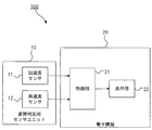
- FIG. 1 is a schematic diagram showing a schematic configuration of the posture improvement support system 100.
- the posture improvement support system 100 shown in FIG. 1 includes a posture determination sensor unit 10 and an electronic device 20.
- the posture determination sensor unit 10 is used by being attached to the body (for example, waist) of the user of the electronic device 20, and the movement of the user (for example) necessary for determining the posture of the user. Outputs information about the movement of the center of gravity of the body, etc.).
- the posture determination sensor unit 10 includes an acceleration sensor 11 and an angular velocity sensor 12.
- the information detected by the acceleration sensor 11 and the information detected by the angular velocity sensor 12 are transmitted to the electronic device 20 via a communication interface (not shown).
- the electronic device 20 is, for example, a smartphone, a tablet terminal, a personal computer, a television, or the like. Specifically, the electronic device 20 includes a control unit 21, a display unit 22, and a communication interface (not shown) for connecting to the posture determination sensor unit 10.
- the control unit 21 includes a CPU (Central Processing Unit), a RAM (Random Access Memory), a ROM (Read Only Memory), and the like, and performs integrated control of the electronic device 20 according to a program.
- a program including a posture improvement support program is stored in the ROM of the control unit 21.
- the display unit 22 is a device capable of displaying an image such as a liquid crystal display panel or an organic EL (electro-luminescence) display panel.
- the display unit 22 may not be built in the electronic device 20 as long as it can be connected to the control unit 21, and may be provided outside the electronic device 20.
- FIG. 2 is a diagram showing a functional block of the control unit 21 of the posture improvement support system 100 shown in FIG.
- the CPU of the control unit 21 functions as the posture acquisition unit 21A and the display control unit 21B by executing the above-mentioned posture improvement support program stored in the ROM.
- the posture acquisition unit 21A is used by determining the posture of the user to which the posture determination sensor unit 10 is attached, based on the detection information received from the acceleration sensor 11 and the angular velocity sensor 12 of the attitude determination sensor unit 10. Acquire information on the posture of the person.
- the sitting posture is to be determined as the posture of the user, for example, an imaging unit capable of imaging the seated user is prepared, and the posture acquisition unit 21A acquires the image captured by the user by the imaging unit. It is also possible for the posture acquisition unit 21A to determine the sitting posture of the user by analyzing this captured image. Further, the posture determination sensor unit 10 is provided with a processor that determines the posture of the user based on the detection information of the acceleration sensor 11 and the angular velocity sensor 12 or the above-mentioned captured image, and the posture information determined here is used. , The posture acquisition unit 21A may acquire the configuration.
- the display control unit 21B determines whether or not the posture of the user acquired by the posture acquisition unit 21A satisfies a predetermined condition (condition for achieving the above-mentioned beautiful posture), and based on the determination result, determines.
- the display condition of the image displayed on the display unit 22 is controlled.
- the conditions for a beautiful posture are, for example, that the amount of deviation of the user's center of gravity in the left-right direction is equal to or less than a predetermined first threshold value (preferably zero) and that the user's center of gravity is biased in the front-back direction. It means that the amount is equal to or less than a predetermined second threshold value (preferably zero), or both.
- the image display condition displayed on the display unit 22 refers to an image display position, an image display size, an image display shape, an image display posture, and the like.
- the display unit 22 can display a screen unrelated to the posture improvement support program.
- the user wears the posture determination sensor unit 10 on his / her body, executes the posture improvement support program on the electronic device 20, and then another application program stored in the ROM of the control unit 21. For example, it is possible to browse a photo on the display unit 22, watch a moving image on the display unit 22, and create a document on the display unit 22.
- the display control unit 21B displays the image displayed on the display unit 22 by such another application program by the application program when the posture of the user acquired by the posture acquisition unit 21A satisfies the above conditions. Display under the determined display conditions (the display conditions at this time are defined as the reference state), and if the user's posture does not meet the above conditions, the display differs from the display conditions determined by the application program. Display according to the conditions.
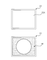
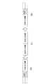
- FIG. 3 is a diagram schematically showing the display unit 22 shown in FIG.
- the display unit 22 has a rectangular display area 22A.
- FIG. 3 an example in which the image IM is displayed in the entire display area 22A is shown.
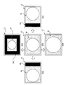
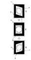
- FIG. 4 is a diagram showing an example of a change in the display form of the image displayed on the display unit 22.
- the display form DS0 shown in FIG. 4 shows a display form when the posture of the user satisfies the condition of the beautiful posture.
- the image IM is displayed at the position (reference position) determined by the other application program described above, as shown in the display form DS0.
- the display form DS1, the display form DS2, the display form DS3, and the display form DS4 shown in FIG. 4 each indicate a display form when the posture of the user does not satisfy the condition of the beautiful posture.
- Display form DS1 shows a display form when the amount of deviation of the user's center of gravity to the right exceeds the first threshold value.
- the image IM is moved to the right with respect to the display form DS0, and a non-display area MG of the image is formed in the display area 22A created by this movement.
- Display form DS2 shows a display form when the amount of deviation of the user's center of gravity to the left exceeds the first threshold value.
- the image IM is moved to the left with respect to the display form DS0, and a non-display area MG of the image is formed in the display area 22A created by this movement.
- Display form DS3 shows a display form when the amount of deviation of the user's center of gravity in the forward direction exceeds the second threshold value.
- the image IM is displayed in a reduced size with respect to the display form DS0, and a non-display area MG of the image is formed in the display area 22A created by this reduction.
- Display form DS4 shows a display form when the amount of deviation of the user's center of gravity in the backward direction exceeds the second threshold value.
- the image IM is enlarged and displayed with respect to the display form DS0, and the entire image IM cannot be confirmed.
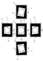
- FIG. 5 is a diagram showing an example of a change in the display form of the image displayed on the display unit 22.
- the display form DS0 shown in FIG. 5 shows a display form when the posture of the user satisfies the condition of the beautiful posture.
- the posture reference posture
- an image IM smaller than the display area 22A is displayed.
- the portion of the display area 22A excluding the image IM is the non-display area MG of the image.
- this reference posture is a posture in which two orthogonal sides of the display area 22A and two orthogonal sides of the image IM are parallel to each other.
- the display form DS1, the display form DS2, the display form DS3, and the display form DS4 shown in FIG. 5 each indicate a display form when the posture of the user does not satisfy the condition of the beautiful posture.
- Display form DS1 shows a display form when the amount of deviation of the user's center of gravity to the right exceeds the first threshold value.
- the image IM is rotated clockwise with respect to the display form DS0, and its display posture is changed.
- Display form DS2 shows a display form when the amount of deviation of the user's center of gravity to the left exceeds the first threshold value.
- the image IM is rotated counterclockwise with respect to the display form DS0, and its display posture is changed.
- Display form DS3 shows a display form when the amount of deviation of the user's center of gravity in the forward direction exceeds the second threshold value.
- the image IM is changed to a shape inclined in the depth direction with respect to the display form DS0, and the display shape is changed.
- Display form DS4 shows, for example, a display form when the amount of deviation of the user's center of gravity in the backward direction exceeds the second threshold value.
- the image IM is changed to a shape inclined toward the front with respect to the display form DS0, and the display shape is changed.
- FIG. 6 is a diagram showing an example of a change in the display form of the image displayed on the display unit 22.
- the display form DS0 shown in FIG. 6 shows a display form when the posture of the user satisfies the condition of the beautiful posture.
- the position is determined by the other application program described above (center of the display area 22A).
- a rectangular image IM smaller than the display area 22A is displayed.
- the portion of the display area 22A excluding the image IM is the non-display area MG of the image.
- the display form DS1 and the display form DS2 shown in FIG. 6 each show a display form when the posture of the user does not satisfy the condition of the beautiful posture.
- Display form DS1 shows a display form when the amount of deviation of the user's center of gravity to the right exceeds the first threshold value.
- the two sides parallel to the short side of the display area 22A in the image IM are in a state of being tilted to the right with respect to the display form DS0, and the display shape thereof is changed.
- Display form DS2 shows a display form when the amount of deviation of the user's center of gravity to the left exceeds the first threshold value.
- the two sides parallel to the short side of the display area 22A in the image IM are tilted to the left with respect to the display form DS0, and the display shape is changed.
- the direction of the change in the display form moving direction of the display position, rotation direction of the image, deformation direction of the image
- the user can move the center of gravity in which direction the image is based on. You can intuitively know if you will return. Therefore, as compared with the conventional case in which a notification sound is used to simply notify that the posture is bad, it is possible to intuitively know the content to be improved in the posture, which can be useful for the posture improvement.
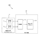
- FIG. 7 is a schematic diagram showing a schematic configuration of the posture improvement support system 200, which is a modification of the posture improvement support system 100 shown in FIG.
- the posture improvement support system 200 shown in FIG. 7 has the same configuration as the posture improvement support system 100 except that the electronic device 20 is replaced with the electronic device 30.
- the electronic device 30 is, for example, a music player, a radio, a smartphone, a tablet terminal, a personal computer, a television, or the like. Specifically, the electronic device 30 includes a control unit 31, a sound output interface 32, and a communication interface (not shown) for connecting to the posture determination sensor unit 10. The electronic device 30 is used by a user who wears the posture determination sensor unit 10.
- the control unit 31 includes a CPU, RAM, ROM, etc., and performs integrated control of the electronic device 30 according to a program.
- a program including a posture improvement support program is stored in the ROM of the control unit 31.
- the sound output interface 32 is an interface for wirelessly or wiredly connecting to a sound output unit such as a stereo earphone or headphone having a right ear earphone and a left ear earphone, a monaural speaker, or a stereo speaker.
- a sound output unit such as a stereo earphone or headphone having a right ear earphone and a left ear earphone, a monaural speaker, or a stereo speaker.
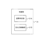
- FIG. 8 is a diagram showing a functional block of the control unit 31 of the posture improvement support system 200 shown in FIG. 7.
- the CPU of the control unit 31 functions as the posture acquisition unit 31A and the sound output control unit 31B by executing the above-mentioned posture improvement support program stored in the ROM. Since the function of the posture acquisition unit 31A is the same as that of the posture acquisition unit 21A of FIG. 2, the description thereof will be omitted.
- the music stored in the ROM is output from the speaker, earphone, or the like via the sound output interface 32. It is possible to make it. Specifically, after the user attaches the posture determination sensor unit 10 to the body and executes the posture improvement support program on the electronic device 30, the user can play music stored in the ROM of the control unit 31. It is possible to execute an application program and listen to music using a speaker, earphone, or headphone connected to the sound output interface 32.
- the sound output control unit 31B determines whether or not the posture of the user acquired by the posture acquisition unit 31A satisfies the above conditions (conditions for achieving the above-mentioned beautiful posture), and based on the determination result, the sound It controls the output condition of the sound output from the sound output unit such as a speaker, earphone, or headphone connected to the output interface 32.
- the sound output conditions are, for example, if the sound output unit connected to the sound output interface 32 is a stereo earphone or headphones, the volume of the sound output from the right ear earphone and the sound output from the left ear earphone. It refers to the balance with the volume of (the absolute value of the difference between these two volumes, or the ratio of these two volumes).
- the sound output condition may be, for example, the content of the sound output from the sound output unit such as an earphone or a speaker connected to the sound output interface 32.
- the sound output from the sound output unit includes sounds from a plurality of sound sources (sound sources such as musical instruments and human voices), it is possible to specify from which sound source the sound is output. , It is a condition to specify which sound source to output the sound at which volume.
- the sound output control unit 31B reproduces the sound output from the sound output unit by such a music playback application program when the posture of the user acquired by the posture acquisition unit 31A satisfies the above conditions.
- Output under the output conditions determined by the application program or user (the output condition at this time is defined as the reference state), and if the user's attitude does not meet the above conditions, the music playback application program or use
- the output conditions are different from the output conditions determined by the person.
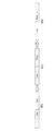
- FIG. 9 is a schematic diagram for explaining the content of changing the output conditions by the sound output control unit 31B shown in FIG.
- FIG. 9 shows an example in which the sound output unit has two sound output units such as a stereo earphone, a stereo speaker, and a stereo headphone.
- the output form OP1 shown in FIG. 9 shows the sound output state from the sound output unit when the posture of the user satisfies the condition of the beautiful posture.
- Each of the output form OP2 and the output form OP3 shown in FIG. 9 shows the output state of the sound from the sound output unit when the posture of the user does not satisfy the condition of the beautiful posture.
- the output form OP2 shows a state when the amount of deviation of the user's center of gravity to the right exceeds the first threshold value.
- the user feels uncomfortable by changing from a state in which the left-right balance of the sound is even to a state in which the left-right balance of the sound is lost.
- the output form OP3 shows a state when the amount of deviation of the user's center of gravity to the left exceeds the first threshold value.
- the user feels uncomfortable by changing from a state in which the left-right balance of the sound is even to a state in which the left-right balance of the sound is lost.
- FIG. 10 is a schematic diagram for explaining another example of the change contents of the output condition by the sound output control unit 31B shown in FIG. FIG. 10 assumes that the sound output from the sound output unit includes sounds from a plurality of sound sources (specifically, music including the sound of a musical instrument and the singing voice of a vocal).
- the sound output from the sound output unit includes sounds from a plurality of sound sources (specifically, music including the sound of a musical instrument and the singing voice of a vocal).
- the output form OP1 shown in FIG. 11 shows the sound output state from the sound output unit when the posture of the user satisfies the condition of the beautiful posture.
- Each of the output form OP2 and the output form OP3 shown in FIG. 11 shows the output state of the sound from the sound output unit when the posture of the user does not satisfy the condition of the beautiful posture.
- the music output from the sound output unit is the sound from all the sound sources included in the music (the sound from the sound source S1 (the sound of the instrument) and the sound from the sound source S2 (the voice of the vocal)). ) Is included. Further, the sound from the sound source S1 and the sound from the sound source S2 have default volumes determined by the music playback application program, the user's settings, and the like, respectively.
- the output form OP2 shows a state when the amount of deviation of the user's center of gravity to the right exceeds the first threshold value.
- the output form OP2 only the sound (vocal voice) from the sound source S2 is changed to a state in which the volume is lowered from the default value.
- the user feels uncomfortable by changing from a state in which the song and the song are heard together to a state in which only the song is difficult to hear.
- the sound from the sound source S2 may be non-output (volume is zero). As a result, the user can be given a further sense of discomfort.
- the output form OP3 shows a state when the amount of deviation of the user's center of gravity to the left exceeds the first threshold value.
- the sound from the sound source S1 for example, the sound of a musical instrument
- the volume is lowered from the default value.
- the user feels uncomfortable by changing from a state in which the song and the song are heard together to a state in which only the song is difficult to hear.
- the sound from the sound source S1 may be non-output (volume is zero). As a result, the user can be given a further sense of discomfort.
- FIG. 11 is a schematic diagram for explaining still another example of the change contents of the output condition by the sound output control unit 31B shown in FIG. FIG. 11 is based on the premise that the sound output from the sound output unit includes sounds from a plurality of sound sources (specifically, music including the sounds of musical instruments and singing voices).
- the output form OP1 shown in FIG. 11 shows the sound output state from the sound output unit when the posture of the user satisfies the condition of the beautiful posture.
- Each of the output form OP2 and the output form OP3 shown in FIG. 11 shows the output state of the sound from the sound output unit when the posture of the user does not satisfy the condition of the beautiful posture.
- the music output from the sound output unit is the sound from all the sound sources included in the music (the sound from the sound source S1 (the sound of the instrument) and the sound from the sound source S2 (the voice of the vocal)). ) Is included. Further, the sound from the sound source S1 and the sound from the sound source S2 have default volumes determined by the music playback application program, the user's settings, and the like, respectively.
- the output form OP2 shows a state when the amount of deviation of the user's center of gravity to the right exceeds the first threshold value.
- only the sound (vocal voice) from the sound source S2 is changed to a state in which the volume is raised from the default value.
- the user feels uncomfortable by changing from a state in which the song and the song are heard together to a state in which only the song is easy to hear.
- the output form OP3 shows a state when the amount of deviation of the user's center of gravity to the left exceeds the first threshold value.
- the sound from the sound source S1 for example, the sound of a musical instrument
- the volume is raised from the default value.
- the direction in which the center of gravity of the user is biased and the change in the sound balance are linked to be used.
- the person can intuitively know in which direction the center of gravity should be moved to restore the sound. Therefore, as compared with the conventional case in which a notification sound is used to simply notify that the posture is bad, it is possible to intuitively know the content to be improved in the posture, which is useful for the posture improvement.
- the user can link the direction in which the center of gravity of the user is biased with the sound of the sound source whose volume changes. You can intuitively know in which direction the center of gravity should be moved to restore the sound. Therefore, as compared with the conventional case in which a notification sound is used to simply notify that the posture is bad, it is possible to intuitively know the content to be improved in the posture, which is useful for the posture improvement.
- Posture improvement support system 10 Posture determination sensor units 20, 30 Electronic devices 21, 31 Control units 21A, 31A Posture acquisition unit 21B Display control unit 22 Display unit 22A Display area 32 Sound output interface 31B Sound output control unit IM Image DS0, DS1, DS2, DS3, DS4 Display form OP1, OP2, OP3 Output form MG non-display area
Landscapes
- Health & Medical Sciences (AREA)
- Life Sciences & Earth Sciences (AREA)
- Heart & Thoracic Surgery (AREA)
- Medical Informatics (AREA)
- Physics & Mathematics (AREA)
- Veterinary Medicine (AREA)
- Biophysics (AREA)
- Pathology (AREA)
- Engineering & Computer Science (AREA)
- Biomedical Technology (AREA)
- Public Health (AREA)
- General Health & Medical Sciences (AREA)
- Molecular Biology (AREA)
- Surgery (AREA)
- Animal Behavior & Ethology (AREA)
- Oral & Maxillofacial Surgery (AREA)
- Physiology (AREA)
- Dentistry (AREA)
- Controls And Circuits For Display Device (AREA)
- User Interface Of Digital Computer (AREA)
Abstract
姿勢改善の動機づけを利用者に強く与えて、良好な姿勢の実現を支援する姿勢改善支援装置、姿勢改善支援方法、及び姿勢改善支援プログラムを提供する。 電子機器(20)の制御部(21)は、表示部(22)を利用する利用者の姿勢の情報を取得する姿勢取得部(21A)と、この姿勢が条件を満たす場合には、表示部(22)に表示されている画像の表示条件を基準状態に制御し、この姿勢が条件を満たしていない場合には、 この表示条件基準状態に対して変化させた状態に制御する表示制御部(21B)と、を備える。
Description
本発明は、姿勢改善支援装置、姿勢改善支援方法、及び姿勢改善支援プログラムに関する。
デスクワーク又は動画視聴時等の座位時の姿勢、或いは、ジョギング又はウォーキングの移動時の姿勢等は、正しい姿勢にて行うことが、身体的な負担を減らしたり、運動パフォーマンスを向上させたりする上で重要である。特許文献1-3には、人に装着されたセンサによってその人の姿勢を検出し、その人に通知することで、正しい姿勢となるよう支援するシステムが記載されている。
ユーザの姿勢を良好なものとするためには、ユーザの姿勢が正しい姿勢から外れている場合に、その状態を効果的にユーザに伝えることが必要である。特許文献1、2には、姿勢が所望の姿勢となっていない場合に報知音を鳴らすことでユーザに報知することが記載されている。しかし、報知音が鳴るだけでは、ユーザへの姿勢の改善の動機づけとしては弱い。特許文献3には、ユーザの動作をモデル化した姿勢モデルを表示することで、ユーザに姿勢を認識させている。しかし、姿勢モデルを見せるだけでは、ユーザへの姿勢の改善の動機づけとしては弱い。
本発明の目的は、姿勢改善の動機づけを利用者に強く与えて、良好な姿勢の実現を支援する姿勢改善支援装置、姿勢改善支援方法、及び姿勢改善支援プログラムを提供する。
(1) 表示部又は音出力部を利用する利用者の姿勢の情報を取得する姿勢取得部と、
前記姿勢が予め決められた条件を満たす場合には、前記表示部に表示されている画像の表示条件又は前記音出力部から出力されている音の出力条件を基準状態に制御し、前記姿勢が前記条件を満たしていない場合には、前記表示条件又は前記出力条件を、前記基準状態に対して変化させた状態に制御する制御部(例えば後述の実施形態の表示制御部21B、音出力制御部31B)と、を備える姿勢改善支援装置(例えば後述の実施形態の制御部21、制御部31)。
前記姿勢が予め決められた条件を満たす場合には、前記表示部に表示されている画像の表示条件又は前記音出力部から出力されている音の出力条件を基準状態に制御し、前記姿勢が前記条件を満たしていない場合には、前記表示条件又は前記出力条件を、前記基準状態に対して変化させた状態に制御する制御部(例えば後述の実施形態の表示制御部21B、音出力制御部31B)と、を備える姿勢改善支援装置(例えば後述の実施形態の制御部21、制御部31)。
(1)によれば、利用者の姿勢が条件を満たしていない状態では、画像の表示条件又は音の出力条件が基準状態から変化した状態に制御されるため、例えば、画像を閲覧する利用者又は音を聞いている利用者に不快感を与えることが可能となる。そのため、この不快感を解消すべく、利用者が自然に姿勢を改善することが期待でき、姿勢改善の動機づけを強く利用者に与えることができる。また、利用者は、この基準状態からの変化によって姿勢の改善の必要性を直感的に把握できると共に、画像の表示条件又は音の出力条件が基準状態に戻るように姿勢を変えるだけで、姿勢が条件を満たす状態を実現することができる。
(2) (1)記載の姿勢改善支援装置であって、
前記表示条件は、前記画像の表示位置に関するものであり、
前記制御部は、前記姿勢が前記条件を満たす場合には、前記表示部に表示されている前記画像の表示位置を基準位置とする前記基準状態に制御し、前記姿勢が前記条件を満たしていない場合には、前記画像の表示位置を前記基準位置とは異なる位置に変更する姿勢改善支援装置。
前記表示条件は、前記画像の表示位置に関するものであり、
前記制御部は、前記姿勢が前記条件を満たす場合には、前記表示部に表示されている前記画像の表示位置を基準位置とする前記基準状態に制御し、前記姿勢が前記条件を満たしていない場合には、前記画像の表示位置を前記基準位置とは異なる位置に変更する姿勢改善支援装置。
(2)によれば、利用者の姿勢が条件を満たしていない場合には、利用者の姿勢が条件を満たしている場合に対して、表示部に表示されている画像の表示位置が、基準位置と異なる位置に変更される。このため、基準位置が例えば利用者の定めた位置であれば、画像の表示位置がこの基準位置からずれたことによる不快感を利用者に与えることができ、この不快感を解消すべく利用者が姿勢改善を行うことが強く期待できるようになる。
(3) (1)記載の姿勢改善支援装置であって、
前記表示条件は、前記画像の表示サイズに関するものであり、
前記制御部は、前記姿勢が前記条件を満たす場合には、前記表示部に表示されている前記画像の表示サイズを基準サイズとする前記基準状態に制御し、前記姿勢が前記条件を満たしていない場合には、前記画像の表示サイズを前記基準サイズとは異なるサイズに変更する姿勢改善支援装置。
前記表示条件は、前記画像の表示サイズに関するものであり、
前記制御部は、前記姿勢が前記条件を満たす場合には、前記表示部に表示されている前記画像の表示サイズを基準サイズとする前記基準状態に制御し、前記姿勢が前記条件を満たしていない場合には、前記画像の表示サイズを前記基準サイズとは異なるサイズに変更する姿勢改善支援装置。
(3)によれば、利用者の姿勢が条件を満たしていない場合には、利用者の姿勢が条件を満たしている場合に対して、表示部に表示されている画像の表示サイズが、基準サイズと異なるサイズに変更される。このため、基準サイズが例えば利用者の定めたサイズであれば、画像の表示サイズがこの基準サイズから変更されたことによる不快感を利用者に与えることができ、この不快感を解消すべく利用者が姿勢改善を行うことが強く期待できるようになる。
(4) (1)記載の姿勢改善支援装置であって、
前記表示条件は、前記画像の表示姿勢に関するものであり、
前記制御部は、前記姿勢が前記条件を満たす場合には、前記表示部に表示されている前記画像の表示姿勢を基準姿勢とする前記基準状態に制御し、前記姿勢が前記条件を満たしていない場合には、前記画像の表示姿勢を前記基準姿勢から回転させた姿勢に変更する姿勢改善支援装置。
前記表示条件は、前記画像の表示姿勢に関するものであり、
前記制御部は、前記姿勢が前記条件を満たす場合には、前記表示部に表示されている前記画像の表示姿勢を基準姿勢とする前記基準状態に制御し、前記姿勢が前記条件を満たしていない場合には、前記画像の表示姿勢を前記基準姿勢から回転させた姿勢に変更する姿勢改善支援装置。
(4)によれば、利用者の姿勢が条件を満たしていない場合には、利用者の姿勢が条件を満たしている場合に対して、表示部に表示されている画像の表示姿勢が、基準姿勢から回転した状態に変更される。このため、基準姿勢が例えば利用者の定めた姿勢であれば、画像の表示姿勢がこの基準姿勢から変更されたことによる不快感を利用者に与えることができ、この不快感を解消すべく利用者が姿勢改善を行うことが強く期待できるようになる。
(5) (1)記載の姿勢改善支援装置であって、
前記表示条件は、前記画像の表示形状に関するものであり、
前記制御部は、前記姿勢が前記条件を満たす場合には、前記表示部に表示されている前記画像の表示形状を基準形状とする前記基準状態に制御し、前記姿勢が前記条件を満たしていない場合には、前記画像の表示形状を前記基準形状とは異なる形状に変更する姿勢改善支援装置。
前記表示条件は、前記画像の表示形状に関するものであり、
前記制御部は、前記姿勢が前記条件を満たす場合には、前記表示部に表示されている前記画像の表示形状を基準形状とする前記基準状態に制御し、前記姿勢が前記条件を満たしていない場合には、前記画像の表示形状を前記基準形状とは異なる形状に変更する姿勢改善支援装置。
(5)によれば、利用者の姿勢が条件を満たしていない場合には、利用者の姿勢が条件を満たしている場合に対して、表示部に表示されている画像の形状が、基準形状から変形される。このため、基準形状が例えば利用者の定めた形状であれば、画像の形状がこの基準形状から変更されたことによる不快感を利用者に与えることができ、この不快感を解消すべく利用者が姿勢改善を行うことが強く期待できるようになる。
(6) (1)記載の姿勢改善支援装置であって、
前記音出力部は、第一音出力部と第二音出力部からなり、
前記出力条件は、前記第一音出力部から出力される前記音の音量と前記第二音出力部から出力される前記音の音量との差又は比に関するものであり、
前記制御部は、前記姿勢が前記条件を満たす場合には、前記差又は前記比を基準値とする前記基準状態に制御し、前記姿勢が前記条件を満たしていない場合には、前記差又は前記比を前記基準値とは異なる値に制御する姿勢改善支援装置。
前記音出力部は、第一音出力部と第二音出力部からなり、
前記出力条件は、前記第一音出力部から出力される前記音の音量と前記第二音出力部から出力される前記音の音量との差又は比に関するものであり、
前記制御部は、前記姿勢が前記条件を満たす場合には、前記差又は前記比を基準値とする前記基準状態に制御し、前記姿勢が前記条件を満たしていない場合には、前記差又は前記比を前記基準値とは異なる値に制御する姿勢改善支援装置。
(6)によれば、利用者の姿勢が条件を満たしていない場合には、利用者の姿勢が条件を満たしている場合に対して、音出力部から出力されている音のバランスを崩すことができる。このため、音の出力バランスが変更されたことによる不快感を利用者に与えることができ、この不快感を解消すべく利用者が姿勢改善を行うことが強く期待できるようになる。
(7) (1)記載の姿勢改善支援装置であって、
前記音は、複数の音源からの音を含む音楽であり、
前記出力条件は、前記音出力部から出力される前記音楽に含まれる前記音源毎の音の音量のバランスに関するものであり、
前記制御部は、前記姿勢が前記条件を満たす場合には、前記複数の前記音源からの音をそれぞれ既定の音量にて前記音出力部から出力させる前記基準状態に制御し、前記姿勢が前記条件を満たしていない場合には、前記複数の前記音源のうちの一部の音源からの音のみ音量を変更する姿勢改善支援装置。
前記音は、複数の音源からの音を含む音楽であり、
前記出力条件は、前記音出力部から出力される前記音楽に含まれる前記音源毎の音の音量のバランスに関するものであり、
前記制御部は、前記姿勢が前記条件を満たす場合には、前記複数の前記音源からの音をそれぞれ既定の音量にて前記音出力部から出力させる前記基準状態に制御し、前記姿勢が前記条件を満たしていない場合には、前記複数の前記音源のうちの一部の音源からの音のみ音量を変更する姿勢改善支援装置。
(7)によれば、利用者の姿勢が条件を満たしていない場合には、利用者の姿勢が条件を満たしている場合に対して、音出力部から出力されている特定音源からの音のみが大きく聞こえすぎたり、小さく聞こえたりする。このため、この音の増減による不快感を利用者に与えることができ、この不快感を解消すべく利用者が姿勢改善を行うことが強く期待できるようになる。
(8) (7)記載の姿勢改善支援装置であって、
前記制御部は、前記姿勢が前記条件を満たしていない場合には、前記一部の前記音源からの音のみ音量をゼロに変更する姿勢改善支援装置。
前記制御部は、前記姿勢が前記条件を満たしていない場合には、前記一部の前記音源からの音のみ音量をゼロに変更する姿勢改善支援装置。
(8)によれば、利用者の姿勢が条件を満たしていない場合には、利用者の姿勢が条件を満たしている場合に対して、音出力部から出力されている音の一部が聞こえなくなる。このため、音の欠如による音のバランスの崩れによって不快感を利用者に与えることができ、この不快感を解消すべく利用者が姿勢改善を行うことが強く期待できるようになる。
(9) (7)記載の姿勢改善支援装置であって、
前記制御部は、前記姿勢が前記条件を満たしていない場合には、前記一部の前記音源からの音のみ音量を増加させる姿勢改善支援装置。
前記制御部は、前記姿勢が前記条件を満たしていない場合には、前記一部の前記音源からの音のみ音量を増加させる姿勢改善支援装置。
(9)によれば、利用者の姿勢が条件を満たしていない場合には、利用者の姿勢が条件を満たしている場合に対して、音出力部から出力されている音の一部が大きくなる。このため、音の増大による音のバランスの崩れによって不快感を利用者に与えることができ、この不快感を解消すべく利用者が姿勢改善を行うことが強く期待できるようになる。
(10) (8)又は(9)記載の姿勢改善支援装置であって、
前記制御部は、前記姿勢に基づく前記利用者の重心の偏り方向に応じて、前記一部の前記音源を変更する姿勢改善支援装置。
前記制御部は、前記姿勢に基づく前記利用者の重心の偏り方向に応じて、前記一部の前記音源を変更する姿勢改善支援装置。
(10)によれば、姿勢をどのようにすれば条件を満たすことができるのかを、利用者に直感的に認識させることができる。
(11)
表示部又は音出力部を利用する利用者の姿勢の情報を取得する姿勢取得ステップと、
前記姿勢が予め決められた条件を満たす場合には、前記表示部に表示されている画像の表示条件又は前記音出力部から出力されている音の出力条件を基準状態に制御し、前記姿勢が前記条件を満たしていない場合には、前記表示条件又は前記出力条件を、前記基準状態に対して変化させた状態に制御する制御ステップと、を備える姿勢改善支援方法。
表示部又は音出力部を利用する利用者の姿勢の情報を取得する姿勢取得ステップと、
前記姿勢が予め決められた条件を満たす場合には、前記表示部に表示されている画像の表示条件又は前記音出力部から出力されている音の出力条件を基準状態に制御し、前記姿勢が前記条件を満たしていない場合には、前記表示条件又は前記出力条件を、前記基準状態に対して変化させた状態に制御する制御ステップと、を備える姿勢改善支援方法。
(12)
表示部又は音出力部を利用する利用者の姿勢の情報を取得する姿勢取得ステップと、
前記姿勢が予め決められた条件を満たす場合には、前記表示部に表示されている画像の表示条件又は前記音出力部から出力されている音の出力条件を基準状態に制御し、前記姿勢が前記条件を満たしていない場合には、前記表示条件又は前記出力条件を、前記基準状態に対して変化させた状態に制御する制御ステップと、をコンピュータに実行させるための姿勢改善支援プログラム。
表示部又は音出力部を利用する利用者の姿勢の情報を取得する姿勢取得ステップと、
前記姿勢が予め決められた条件を満たす場合には、前記表示部に表示されている画像の表示条件又は前記音出力部から出力されている音の出力条件を基準状態に制御し、前記姿勢が前記条件を満たしていない場合には、前記表示条件又は前記出力条件を、前記基準状態に対して変化させた状態に制御する制御ステップと、をコンピュータに実行させるための姿勢改善支援プログラム。
本発明によれば、姿勢改善の動機づけを利用者に強く与えて、良好な姿勢の実現を支援する姿勢改善支援装置、姿勢改善支援方法、及び姿勢改善支援プログラムを提供することができる。
(実施形態の姿勢改善支援システムの概要)
実施形態の姿勢改善支援システムは、利用者の姿勢が身体に負担の少ない良好な姿勢(以下、美姿勢という)となるように支援を行うものである。姿勢改善支援システムに含まれる姿勢改善支援装置は、利用者の姿勢を、利用者に装着された動き検出センサの出力情報や、利用者の撮像画像等に基づいて判定する。そして、姿勢改善支援装置は、判定した利用者の姿勢が美姿勢の条件を満たしている場合には、その利用者が観察中の表示部に、画像を通常の表示形態にて表示させる。
実施形態の姿勢改善支援システムは、利用者の姿勢が身体に負担の少ない良好な姿勢(以下、美姿勢という)となるように支援を行うものである。姿勢改善支援システムに含まれる姿勢改善支援装置は、利用者の姿勢を、利用者に装着された動き検出センサの出力情報や、利用者の撮像画像等に基づいて判定する。そして、姿勢改善支援装置は、判定した利用者の姿勢が美姿勢の条件を満たしている場合には、その利用者が観察中の表示部に、画像を通常の表示形態にて表示させる。
一方、姿勢改善支援装置は、判定した利用者の姿勢が美姿勢の条件を満たしていない場合には、その利用者が観察中の表示部に表示されていた画像の位置、サイズ、傾き、又は形状等を変更する。例えば、利用者の姿勢が美姿勢から遠ざかると、表示部の中央に表示されていた画像が左右に移動したり、その画像が回転したり、その画像が大きくなったり、その画像が小さくなったり、その画像の形状が矩形から菱形に変化したり、といった画像の表示形態の変化が生じる。これにより、この画像を閲覧している利用者に不快感を与えることが可能となる。そのため、この不快感を解消すべく、利用者が自然に姿勢を改善するよう努力することが期待でき、姿勢改善の動機づけを強く利用者に与えることができる。
(実施形態の姿勢改善支援システムの具体的構成)
図1は、姿勢改善支援システム100の概略構成を示す模式図である。図1に示す姿勢改善支援システム100は、姿勢判定用センサユニット10と、電子機器20と、を備える。
図1は、姿勢改善支援システム100の概略構成を示す模式図である。図1に示す姿勢改善支援システム100は、姿勢判定用センサユニット10と、電子機器20と、を備える。
姿勢判定用センサユニット10は、電子機器20の利用者の身体(例えば腰等)に装着されて使用されるものであり、この利用者の姿勢を判定するために必要な利用者の動き(例えば身体の重心の動き等)に関する情報を出力する。
姿勢判定用センサユニット10は、図1の例では、加速度センサ11と、角速度センサ12と、を含む。加速度センサ11によって検出された情報と、角速度センサ12によって検出された情報は、図示省略の通信インタフェースを介して、電子機器20に送信される。
電子機器20は、例えば、スマートフォン、タブレット型端末、パーソナルコンピュータ、又はテレビ等である。具体的には、電子機器20は、制御部21と、表示部22と、姿勢判定用センサユニット10と接続するための通信インタフェース(図示省略)と、を備える。
制御部21は、CPU(Central Processing Unit)、RAM(Random Access Memory)、及びROM(Read Only Memory)等を含み、プログラムにしたがって電子機器20の統括制御等を行う。制御部21のROMには、姿勢改善支援プログラムを含むプログラムが記憶されている。
表示部22は、液晶表示パネル又は有機EL(electro-luminescence)表示パネル等の画像を表示可能なデバイスである。なお、表示部22は、制御部21と接続可能であれば、電子機器20に内蔵されていなくてもよく、電子機器20の外部に設けられたものであってもよい。
(制御部21の機能)
図2は、図1に示す姿勢改善支援システム100の制御部21の機能ブロックを示す図である。制御部21のCPUは、ROMに記憶された上記の姿勢改善支援プログラムを実行することにより、姿勢取得部21A及び表示制御部21Bとして機能する。
図2は、図1に示す姿勢改善支援システム100の制御部21の機能ブロックを示す図である。制御部21のCPUは、ROMに記憶された上記の姿勢改善支援プログラムを実行することにより、姿勢取得部21A及び表示制御部21Bとして機能する。
姿勢取得部21Aは、姿勢判定用センサユニット10の加速度センサ11及び角速度センサ12から受信した検出情報に基づいて、姿勢判定用センサユニット10が装着された利用者の姿勢を判定することで、利用者の姿勢の情報を取得する。
なお、利用者の姿勢として座位の姿勢を判定するのであれば、例えば、着座した利用者を撮像可能な撮像部を用意し、この撮像部による利用者の撮像画像を姿勢取得部21Aが取得し、姿勢取得部21Aがこの撮像画像を解析することで、利用者の座位姿勢を判定することも可能である。また、姿勢判定用センサユニット10に、加速度センサ11及び角速度センサ12の検出情報又は上記の撮像画像に基づいて利用者の姿勢を判定するプロセッサを設けておき、ここで判定された姿勢の情報を、姿勢取得部21Aが取得する構成としてもよい。
表示制御部21Bは、姿勢取得部21Aにより取得された利用者の姿勢が、予め決められた条件(上述した美姿勢となる条件)を満たすか否かを判定し、その判定結果に基づいて、表示部22に表示されている画像の表示条件を制御する。
美姿勢となる条件とは、例えば、利用者の重心の左右方向への偏り量が予め決められた第一閾値以下(好ましくはゼロ)となることと、利用者の重心の前後方向への偏り量が予め決められた第二閾値以下(好ましくはゼロ)となること、の一方又は両方をいう。
表示部22に表示されている画像の表示条件とは、画像の表示位置、画像の表示サイズ、画像の表示形状、又は画像の表示姿勢等のことをいう。
電子機器20では、制御部21のCPUが姿勢改善支援プログラムを実行している状態であっても、表示部22に、姿勢改善支援プログラムとは無関係の画面を表示させることが可能である。具体的には、利用者は、姿勢判定用センサユニット10を身体に装着し、電子機器20にて姿勢改善支援プログラムを実行した後は、制御部21のROMに格納されている他のアプリケーションプログラムを実行して、例えば、表示部22にて写真の閲覧を行ったり、表示部22にて動画を視聴したり、表示部22にて文書作成を行ったりすることが可能である。
表示制御部21Bは、こういった他のアプリケーションプログラムによって表示部22に表示されている画像を、姿勢取得部21Aにより取得された利用者の姿勢が上記条件を満たす場合には、そのアプリケーションプログラムによって決められた表示条件にて表示させ(このときの表示条件を基準状態と定義する)、利用者の姿勢が上記条件を満たさない場合には、そのアプリケーションプログラムによって決められた表示条件とは異なる表示条件にて表示させる。
図3は、図1に示す表示部22を模式的に示す図である。表示部22は、矩形の表示領域22Aを有している。図3の下段には、表示領域22Aの全体に画像IMが表示された例が示されている。
(画像の表示条件の変化の第一の例)
図4は、表示部22に表示されている画像の表示形態の変化例を示す図である。図4に示す表示形態DS0は、利用者の姿勢が美姿勢の条件を満たしている場合の表示形態を示している。利用者の姿勢が美姿勢の条件を満たしている場合には、表示形態DS0に示すように、上述した他のアプリケーションプログラムによって決められた位置(基準位置)に画像IMが表示されている。
図4は、表示部22に表示されている画像の表示形態の変化例を示す図である。図4に示す表示形態DS0は、利用者の姿勢が美姿勢の条件を満たしている場合の表示形態を示している。利用者の姿勢が美姿勢の条件を満たしている場合には、表示形態DS0に示すように、上述した他のアプリケーションプログラムによって決められた位置(基準位置)に画像IMが表示されている。
図4に示す表示形態DS1、表示形態DS2、表示形態DS3、及び表示形態DS4は、それぞれ、利用者の姿勢が美姿勢の条件を満たしていない場合の表示形態を示している。
表示形態DS1は、利用者の重心の右方向への偏り量が第一閾値を超えている場合の表示形態を示している。表示形態DS1においては、画像IMが、表示形態DS0に対して右方向に移動されており、この移動によってあいた表示領域22Aには、画像の非表示領域MGが形成されている。
表示形態DS2は、利用者の重心の左方向への偏り量が第一閾値を超えている場合の表示形態を示している。表示形態DS2においては、画像IMが、表示形態DS0に対して左方向に移動されており、この移動によってあいた表示領域22Aには、画像の非表示領域MGが形成されている。
表示形態DS3は、利用者の重心の前方向への偏り量が第二閾値を超えている場合の表示形態を示している。表示形態DS3においては、画像IMが、表示形態DS0に対して縮小して表示されており、この縮小によってあいた表示領域22Aには、画像の非表示領域MGが形成されている。
表示形態DS4は、利用者の重心の後ろ方向への偏り量が第二閾値を超えている場合の表示形態を示している。表示形態DS4においては、画像IMが、表示形態DS0に対して拡大して表示されており、画像IMの全体が確認できない状態となっている。
(画像の表示条件の変化の第二の例)
図5は、表示部22に表示されている画像の表示形態の変化例を示す図である。図5に示す表示形態DS0は、利用者の姿勢が美姿勢の条件を満たしている場合の表示形態を示している。図5の例では、利用者の姿勢が美姿勢の条件を満たしている場合には、表示形態DS0に示すように、上述した他のアプリケーションプログラムや利用者によって決められた姿勢(基準姿勢)にて、表示領域22Aよりも小さい画像IMが表示されている。表示領域22Aのうち、画像IMを除く部分は、画像の非表示領域MGとなっている。この基準姿勢は、図5の例では、表示領域22Aの直交する2辺と画像IMの直交する2辺とが平行となる姿勢である。
図5は、表示部22に表示されている画像の表示形態の変化例を示す図である。図5に示す表示形態DS0は、利用者の姿勢が美姿勢の条件を満たしている場合の表示形態を示している。図5の例では、利用者の姿勢が美姿勢の条件を満たしている場合には、表示形態DS0に示すように、上述した他のアプリケーションプログラムや利用者によって決められた姿勢(基準姿勢)にて、表示領域22Aよりも小さい画像IMが表示されている。表示領域22Aのうち、画像IMを除く部分は、画像の非表示領域MGとなっている。この基準姿勢は、図5の例では、表示領域22Aの直交する2辺と画像IMの直交する2辺とが平行となる姿勢である。
図5に示す表示形態DS1、表示形態DS2、表示形態DS3、及び表示形態DS4は、それぞれ、利用者の姿勢が美姿勢の条件を満たしていない場合の表示形態を示している。
表示形態DS1は、利用者の重心の右方向への偏り量が第一閾値を超えている場合の表示形態を示している。表示形態DS1においては、画像IMが、表示形態DS0に対して右回りに回転されており、その表示姿勢が変更されている。
表示形態DS2は、利用者の重心の左方向への偏り量が第一閾値を超えている場合の表示形態を示している。表示形態DS2においては、画像IMが、表示形態DS0に対して左回りに回転されており、その表示姿勢が変更されている。
表示形態DS3は、利用者の重心の前方向への偏り量が第二閾値を超えている場合の表示形態を示している。表示形態DS3においては、画像IMが、表示形態DS0に対して奥行き方向に傾いた形状に変更されて、その表示形状が変更されている。
表示形態DS4は、例えば、利用者の重心の後ろ方向への偏り量が第二閾値を超えている場合の表示形態を示している。表示形態DS4においては、画像IMが、表示形態DS0に対して手前方向に傾いた形状に変更されて、その表示形状が変更されている。
(画像の表示条件の変化の第三の例)
図6は、表示部22に表示されている画像の表示形態の変化例を示す図である。図6に示す表示形態DS0は、利用者の姿勢が美姿勢の条件を満たしている場合の表示形態を示している。図6の例では、利用者の姿勢が美姿勢の条件を満たしている場合には、表示形態DS0に示すように、上述した他のアプリケーションプログラムによって決められた位置(表示領域22Aの中心)に、表示領域22Aよりも小さい矩形の画像IMが表示されている。表示領域22Aのうち、画像IMを除く部分は、画像の非表示領域MGとなっている。
図6は、表示部22に表示されている画像の表示形態の変化例を示す図である。図6に示す表示形態DS0は、利用者の姿勢が美姿勢の条件を満たしている場合の表示形態を示している。図6の例では、利用者の姿勢が美姿勢の条件を満たしている場合には、表示形態DS0に示すように、上述した他のアプリケーションプログラムによって決められた位置(表示領域22Aの中心)に、表示領域22Aよりも小さい矩形の画像IMが表示されている。表示領域22Aのうち、画像IMを除く部分は、画像の非表示領域MGとなっている。
図6に示す表示形態DS1及び表示形態DS2は、それぞれ、利用者の姿勢が美姿勢の条件を満たしていない場合の表示形態を示している。
表示形態DS1は、利用者の重心の右方向への偏り量が第一閾値を超えている場合の表示形態を示している。表示形態DS1においては、画像IMにおける表示領域22Aの短辺に平行な2辺が、表示形態DS0に対し右方向に傾いた状態となっており、その表示形状が変更されている。
表示形態DS2は、利用者の重心の左方向への偏り量が第一閾値を超えている場合の表示形態を示している。表示形態DS2においては、画像IMにおける表示領域22Aの短辺に平行な2辺が、表示形態DS0に対し左方向に傾いた状態となっており、その表示形状が変更されている。
(姿勢改善支援システム100の効果)
以上のように、姿勢改善支援システム100によれば、表示部22を観察している利用者の姿勢が美姿勢の条件を満たしていない場合には、図4、図5、又は図6に例示したように、表示部22に表示されている画像の表示形態が、表示形態DS0から変更されることで、この画像の視認性を低下させることができる。この結果、利用者は画像の表示形態の変化によって不快感を持つため、この不快感を解消すべく、自身の姿勢を改善して、画像の表示形態を元に戻すよう努力することになる。したがって、利用者に対し、姿勢改善のための動機づけを強く与えることができ、利用者の姿勢を良好なものに維持することが可能になる。
以上のように、姿勢改善支援システム100によれば、表示部22を観察している利用者の姿勢が美姿勢の条件を満たしていない場合には、図4、図5、又は図6に例示したように、表示部22に表示されている画像の表示形態が、表示形態DS0から変更されることで、この画像の視認性を低下させることができる。この結果、利用者は画像の表示形態の変化によって不快感を持つため、この不快感を解消すべく、自身の姿勢を改善して、画像の表示形態を元に戻すよう努力することになる。したがって、利用者に対し、姿勢改善のための動機づけを強く与えることができ、利用者の姿勢を良好なものに維持することが可能になる。
特に、図4の表示形態DS1及び表示形態DS2、図5の表示形態DS1~DS4、又は、図6の表示形態DS1及び表示形態DS2のように、利用者の重心の偏っている方向と、画像の表示形態の変化(表示位置の移動方向、画像の回転方向、画像の変形方向)の方向とをリンクさせておくことで、利用者は、どの方向に重心を移動させれば画像が元に戻るのかを直感的に知ることができる。このため、単純に報知音によって姿勢が悪いことを知らせる従来と比較すると、姿勢の改善すべき内容を直感的に知ることができ、姿勢改善に役立てることができる。
(変形例)
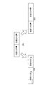
図7は、図1に示す姿勢改善支援システム100の変形例である姿勢改善支援システム200の概略構成を示す模式図である。図7に示す姿勢改善支援システム200は、電子機器20が電子機器30に置換された点を除いては、姿勢改善支援システム100と同じ構成である。
図7は、図1に示す姿勢改善支援システム100の変形例である姿勢改善支援システム200の概略構成を示す模式図である。図7に示す姿勢改善支援システム200は、電子機器20が電子機器30に置換された点を除いては、姿勢改善支援システム100と同じ構成である。
電子機器30は、例えば、音楽プレーヤ、ラジオ、スマートフォン、タブレット型端末、パーソナルコンピュータ、又はテレビ等である。具体的には、電子機器30は、制御部31と、音出力用インタフェース32と、姿勢判定用センサユニット10と接続するための通信インタフェース(図示省略)と、を備える。電子機器30は、姿勢判定用センサユニット10を装着した利用者によって使用される。
制御部31は、CPU、RAM、及びROM等を含み、プログラムにしたがって電子機器30の統括制御等を行う。制御部31のROMには、姿勢改善支援プログラムを含むプログラムが記憶されている。
音出力用インタフェース32は、右耳用イヤホン及び左耳用イヤホンを有するステレオイヤホン又はヘッドホン、モノラルスピーカ、ステレオスピーカ等の音出力部と、無線又は有線によって接続するためのインタフェースである。
図8は、図7に示す姿勢改善支援システム200の制御部31の機能ブロックを示す図である。制御部31のCPUは、ROMに記憶された上記の姿勢改善支援プログラムを実行することにより、姿勢取得部31A及び音出力制御部31Bとして機能する。姿勢取得部31Aの機能は、図2の姿勢取得部21Aと同じであるため説明を省略する。
電子機器30では、制御部31のCPUが姿勢改善支援プログラムを実行している状態であっても、音出力用インタフェース32を介して、ROMに記憶されている音楽を、スピーカ又はイヤホン等から出力させることが可能である。具体的には、利用者は、姿勢判定用センサユニット10を身体に装着し、電子機器30にて姿勢改善支援プログラムを実行した後は、制御部31のROMに格納されている音楽再生用のアプリケーションプログラムを実行して、音出力用インタフェース32と接続されたスピーカ、イヤホン、又はヘッドホンを用いて、音楽を聴くことが可能である。
音出力制御部31Bは、姿勢取得部31Aにより取得された利用者の姿勢が、上記の条件(上述した美姿勢となる条件)を満たすか否かを判定し、その判定結果に基づいて、音出力用インタフェース32と接続されているスピーカ、イヤホン、又はヘッドホン等の音出力部から出力されている音の出力条件を制御する。
音の出力条件とは、例えば、音出力用インタフェース32と接続されている音出力部がステレオイヤホンやヘッドホンであれば、右耳用イヤホンから出力させる音の音量と左耳用イヤホンから出力させる音の音量とのバランス(この2つの音量の差の絶対値、又は、この2つの音量の比)のことを言う。
また、音の出力条件とは、例えば、音出力用インタフェース32と接続されているイヤホンやスピーカ等の音出力部から出力させる音の内容であってもよい。具体的には、音出力部から出力されている音が、複数の音源(楽器、人の声等の音源)からの音を含む場合に、どの音源からの音を出力させるかを規定したり、どの音源からの音をどの音量にて出力させるかを規定したりする条件である。
音出力制御部31Bは、こういった音楽再生アプリケーションプログラムによって音出力部から出力されている音を、姿勢取得部31Aにより取得された利用者の姿勢が上記条件を満たす場合には、その音楽再生アプリケーションプログラムや利用者によって決められた出力条件にて出力させ(このときの出力条件を基準状態と定義する)、利用者の姿勢が上記条件を満たさない場合には、その音楽再生アプリケーションプログラムや利用者によって決められた出力条件とは異なる出力条件にて出力させる。
(音の出力条件の変化の第一の例)
図9は、図8に示す音出力制御部31Bによる出力条件の変更内容を説明するための模式図である。図9は、音出力部がステレオイヤホン、ステレオスピーカ、又はステレオヘッドホン等の2つの音出力部を有するものである場合を例にしている。
図9は、図8に示す音出力制御部31Bによる出力条件の変更内容を説明するための模式図である。図9は、音出力部がステレオイヤホン、ステレオスピーカ、又はステレオヘッドホン等の2つの音出力部を有するものである場合を例にしている。
図9に示す出力形態OP1は、利用者の姿勢が美姿勢の条件を満たしている場合の音出力部からの音の出力状態を示している。図9に示す出力形態OP2及び出力形態OP3は、それぞれ、利用者の姿勢が美姿勢の条件を満たしていない場合の音出力部からの音の出力状態を示している。
出力形態OP1においては、音出力部における右耳用の第一音出力部から出力される音の音量Routと、音出力部における左耳用の第二音出力部から出力される音の音量Loutとは、音楽再生アプリケーションプログラム又は利用者による設定によって決められた同じ値となっている。つまり、音量Routと音量Loutとの差はゼロ(基準値)となっている。換言すると、音量Routと音量Loutの比(=Rout/Lout)は “1”(基準値)となっている。
出力形態OP2は、利用者の重心の右方向への偏り量が第一閾値を超えている場合の状態を示している。出力形態OP2においては、第一音出力部から出力される音の音量Routのみが、出力形態OP1のときと比較して低下されている。つまり、音量Routと音量Loutとの差はゼロよりも十分に大きくなっている。換言すると、音量Routと音量Loutの比(=Rout/Lout)は“1”よりも十分に小さくなっている。これにより、利用者は、音の左右バランスが均等であった状態から、音の左右バランスが崩れた状態に変化することで違和感を覚えることになる。
出力形態OP3は、利用者の重心の左方向への偏り量が第一閾値を超えている場合の状態を示している。出力形態OP3においては、第二音出力部から出力される音の音量Loutのみが、出力形態OP1のときと比較して低下されている。つまり、音量Routと音量Loutとの差はゼロよりも十分に大きくなっている。換言すると、音量Routと音量Loutの比(=Rout/Lout)は“1”よりも十分に大きくなっている。これにより、利用者は、音の左右バランスが均等であった状態から、音の左右バランスが崩れた状態に変化することで違和感を覚えることになる。
(音の出力条件の変化の第二の例)
図10は、図8に示す音出力制御部31Bによる出力条件の変更内容の別の例説明するための模式図である。図10は、音出力部から出力されている音が、複数の音源からの音を含むもの(具体的には、楽器の音とボーカルの歌声とを含む音楽)であることを前提としている。
図10は、図8に示す音出力制御部31Bによる出力条件の変更内容の別の例説明するための模式図である。図10は、音出力部から出力されている音が、複数の音源からの音を含むもの(具体的には、楽器の音とボーカルの歌声とを含む音楽)であることを前提としている。
図11に示す出力形態OP1は、利用者の姿勢が美姿勢の条件を満たしている場合の音出力部からの音の出力状態を示している。図11に示す出力形態OP2及び出力形態OP3は、それぞれ、利用者の姿勢が美姿勢の条件を満たしていない場合の音出力部からの音の出力状態を示している。
出力形態OP1においては、音出力部から出力される音楽が、その音楽に含まれる全ての音源からの音(音源S1からの音(楽器の音)と、音源S2からの音(ボーカルの声))を含む状態となっている。また、音源S1からの音と、音源S2からの音は、それぞれ、音楽再生アプリケーションプログラムや利用者の設定等によって決められた既定の音量となっている。
出力形態OP2は、利用者の重心の右方向への偏り量が第一閾値を超えている場合の状態を示している。出力形態OP2においては、音源S2からの音(ボーカルの声)のみ、音量が既定値から低下した状態に変更されている。これにより、利用者は、歌と曲が一緒に聞こえていた状態から、歌のみが聞こえにくい状態に変化することで違和感を覚えることになる。なお、出力形態OP2においては、音源S2からの音を非出力(音量をゼロ)としてもよい。これにより、更なる違和感を利用者に与えることができる。
出力形態OP3は、利用者の重心の左方向への偏り量が第一閾値を超えている場合の状態を示している。出力形態OP3においては、音源S1からの音(例えば楽器の音)のみ、音量が既定値から低下した状態に変更されている。これにより、利用者は、歌と曲が一緒に聞こえていた状態から、曲のみが聞こえにくい状態に変化することで違和感を覚えることになる。なお、出力形態OP3においては、音源S1からの音を非出力(音量をゼロ)としてもよい。これにより、更なる違和感を利用者に与えることができる。
(音の出力条件の変化の第三の例)
図11は、図8に示す音出力制御部31Bによる出力条件の変更内容の更に別の例を説明するための模式図である。図11は、音出力部から出力されている音が、複数の音源からの音を含むもの(具体的には、楽器の音と歌声とを含む音楽)であることを前提としている。
図11は、図8に示す音出力制御部31Bによる出力条件の変更内容の更に別の例を説明するための模式図である。図11は、音出力部から出力されている音が、複数の音源からの音を含むもの(具体的には、楽器の音と歌声とを含む音楽)であることを前提としている。
図11に示す出力形態OP1は、利用者の姿勢が美姿勢の条件を満たしている場合の音出力部からの音の出力状態を示している。図11に示す出力形態OP2及び出力形態OP3は、それぞれ、利用者の姿勢が美姿勢の条件を満たしていない場合の音出力部からの音の出力状態を示している。
出力形態OP1においては、音出力部から出力される音楽が、その音楽に含まれる全ての音源からの音(音源S1からの音(楽器の音)と、音源S2からの音(ボーカルの声))を含む状態となっている。また、音源S1からの音と、音源S2からの音は、それぞれ、音楽再生アプリケーションプログラムや利用者の設定等によって決められた既定の音量となっている。
出力形態OP2は、利用者の重心の右方向への偏り量が第一閾値を超えている場合の状態を示している。出力形態OP2においては、音源S2からの音(ボーカルの声)のみ音量が既定値から上昇した状態に変更されている。これにより、利用者は、歌と曲が一緒に聞こえていた状態から、歌のみが聞こえやすい状態に変化することで違和感を覚えることになる。
出力形態OP3は、利用者の重心の左方向への偏り量が第一閾値を超えている場合の状態を示している。出力形態OP3においては、音源S1からの音(例えば楽器の音)のみ音量が既定値から上昇した状態に変更されている。これにより、利用者は、歌と曲が一緒に聞こえていた状態から、曲のみが聞こえやすい状態に変化することで違和感を覚えることになる。
(変形例の姿勢改善支援システム200の効果)
以上のように、姿勢改善支援システム200によれば、イヤホンやスピーカ等を用いて音を聴いている利用者の姿勢が美姿勢の条件を満たしていない場合には、図9、図10、及び図11に例示したように、その音のバランスが崩れたり、特定の音のみが聞こえなくなったり、特定の音のみが聞こえやすくなったりする。この結果、利用者は、音の変化によって不快感を持つため、この不快感を解消すべく、自身の姿勢を改善して、音の出力形態を元に戻すよう努力することになる。したがって、利用者に対し、姿勢改善のための動機づけを強く与えることができ、利用者の姿勢を良好なものに維持することが可能になる。
以上のように、姿勢改善支援システム200によれば、イヤホンやスピーカ等を用いて音を聴いている利用者の姿勢が美姿勢の条件を満たしていない場合には、図9、図10、及び図11に例示したように、その音のバランスが崩れたり、特定の音のみが聞こえなくなったり、特定の音のみが聞こえやすくなったりする。この結果、利用者は、音の変化によって不快感を持つため、この不快感を解消すべく、自身の姿勢を改善して、音の出力形態を元に戻すよう努力することになる。したがって、利用者に対し、姿勢改善のための動機づけを強く与えることができ、利用者の姿勢を良好なものに維持することが可能になる。
特に、図9の出力形態OP2及び出力形態OP3のように、利用者の重心の偏っている方向と、音のバランスの変化(音量を下げる音出力部)とをリンクさせておくことで、利用者は、どの方向に重心を移動させれば音が元に戻るのかを直感的に知ることができる。このため、単純に報知音によって姿勢が悪いことを知らせる従来と比較すると、姿勢の改善すべき内容を直感的に知ることができ、姿勢改善に役立てることができる。
また、図10及び図11の出力形態OP2及び出力形態OP3のように、利用者の重心の偏っている方向と、音量が変化する音源の音とをリンクさせておくことで、利用者は、どの方向に重心を移動させれば音が元に戻るのかを直感的に知ることができる。このため、単純に報知音によって姿勢が悪いことを知らせる従来と比較すると、姿勢の改善すべき内容を直感的に知ることができ、姿勢改善に役立てることができる。
以上、図面を参照しながら各種の実施の形態について説明したが、本発明はかかる例に限定されないことは言うまでもない。当業者であれば、特許請求の範囲に記載された範疇内において、各種の変更例又は修正例に想到し得ることは明らかであり、それらについても当然に本発明の技術的範囲に属するものと了解される。また、発明の趣旨を逸脱しない範囲において、上記実施の形態における各構成要素を任意に組み合わせてもよい。
なお、本出願は、2019年3月12日出願の日本特許出願(特願2019-044981)に基づくものであり、その内容は本出願の中に参照として援用される。
100、200 姿勢改善支援システム
10 姿勢判定用センサユニット
20、30 電子機器
21、31 制御部
21A、31A 姿勢取得部
21B 表示制御部
22 表示部
22A 表示領域
32 音出力用インタフェース
31B 音出力制御部
IM 画像
DS0、DS1、DS2、DS3、DS4 表示形態
OP1、OP2、OP3 出力形態
MG 非表示領域
10 姿勢判定用センサユニット
20、30 電子機器
21、31 制御部
21A、31A 姿勢取得部
21B 表示制御部
22 表示部
22A 表示領域
32 音出力用インタフェース
31B 音出力制御部
IM 画像
DS0、DS1、DS2、DS3、DS4 表示形態
OP1、OP2、OP3 出力形態
MG 非表示領域
Claims (12)
- 表示部又は音出力部を利用する利用者の姿勢の情報を取得する姿勢取得部と、
前記姿勢が予め決められた条件を満たす場合には、前記表示部に表示されている画像の表示条件又は前記音出力部から出力されている音の出力条件を基準状態に制御し、前記姿勢が前記条件を満たしていない場合には、前記表示条件又は前記出力条件を、前記基準状態に対して変化させた状態に制御する制御部と、を備える姿勢改善支援装置。 - 請求項1記載の姿勢改善支援装置であって、
前記表示条件は、前記画像の表示位置に関するものであり、
前記制御部は、前記姿勢が前記条件を満たす場合には、前記表示部に表示されている前記画像の表示位置を基準位置とする前記基準状態に制御し、前記姿勢が前記条件を満たしていない場合には、前記画像の表示位置を前記基準位置とは異なる位置に変更する姿勢改善支援装置。 - 請求項1記載の姿勢改善支援装置であって、
前記表示条件は、前記画像の表示サイズに関するものであり、
前記制御部は、前記姿勢が前記条件を満たす場合には、前記表示部に表示されている前記画像の表示サイズを基準サイズとする前記基準状態に制御し、前記姿勢が前記条件を満たしていない場合には、前記画像の表示サイズを前記基準サイズとは異なるサイズに変更する姿勢改善支援装置。 - 請求項1記載の姿勢改善支援装置であって、
前記表示条件は、前記画像の表示姿勢に関するものであり、
前記制御部は、前記姿勢が前記条件を満たす場合には、前記表示部に表示されている前記画像の表示姿勢を基準姿勢とする前記基準状態に制御し、前記姿勢が前記条件を満たしていない場合には、前記画像の表示姿勢を前記基準姿勢から回転させた姿勢に変更する姿勢改善支援装置。 - 請求項1記載の姿勢改善支援装置であって、
前記表示条件は、前記画像の表示形状に関するものであり、
前記制御部は、前記姿勢が前記条件を満たす場合には、前記表示部に表示されている前記画像の表示形状を基準形状とする前記基準状態に制御し、前記姿勢が前記条件を満たしていない場合には、前記画像の表示形状を前記基準形状とは異なる形状に変更する姿勢改善支援装置。 - 請求項1記載の姿勢改善支援装置であって、
前記音出力部は、第一音出力部と第二音出力部からなり、
前記出力条件は、前記第一音出力部から出力される前記音の音量と前記第二音出力部から出力される前記音の音量との差又は比に関するものであり、
前記制御部は、前記姿勢が前記条件を満たす場合には、前記差又は前記比を基準値とする前記基準状態に制御し、前記姿勢が前記条件を満たしていない場合には、前記差又は前記比を前記基準値とは異なる値に制御する姿勢改善支援装置。 - 請求項1記載の姿勢改善支援装置であって、
前記音は、複数の音源からの音を含む音楽であり、
前記出力条件は、前記音出力部から出力される前記音楽に含まれる前記音源毎の音の音量のバランスに関するものであり、
前記制御部は、前記姿勢が前記条件を満たす場合には、前記複数の前記音源からの音をそれぞれ既定の音量にて前記音出力部から出力させる前記基準状態に制御し、前記姿勢が前記条件を満たしていない場合には、前記複数の前記音源のうちの一部の音源からの音のみ音量を変更する姿勢改善支援装置。 - 請求項7記載の姿勢改善支援装置であって、
前記制御部は、前記姿勢が前記条件を満たしていない場合には、前記一部の前記音源からの音のみ音量をゼロに変更する姿勢改善支援装置。 - 請求項7記載の姿勢改善支援装置であって、
前記制御部は、前記姿勢が前記条件を満たしていない場合には、前記一部の前記音源からの音のみ音量を増加させる姿勢改善支援装置。 - 請求項8又は9記載の姿勢改善支援装置であって、
前記制御部は、前記姿勢に基づく前記利用者の重心の偏り方向に応じて、前記一部の前記音源を変更する姿勢改善支援装置。 - 表示部又は音出力部を利用する利用者の姿勢の情報を取得する姿勢取得ステップと、
前記姿勢が予め決められた条件を満たす場合には、前記表示部に表示されている画像の表示条件又は前記音出力部から出力されている音の出力条件を基準状態に制御し、前記姿勢が前記条件を満たしていない場合には、前記表示条件又は前記出力条件を、前記基準状態に対して変化させた状態に制御する制御ステップと、を備える姿勢改善支援方法。 - 表示部又は音出力部を利用する利用者の姿勢の情報を取得する姿勢取得ステップと、
前記姿勢が予め決められた条件を満たす場合には、前記表示部に表示されている画像の表示条件又は前記音出力部から出力されている音の出力条件を基準状態に制御し、前記姿勢が前記条件を満たしていない場合には、前記表示条件又は前記出力条件を、前記基準状態に対して変化させた状態に制御する制御ステップと、をコンピュータに実行させるための姿勢改善支援プログラム。
Priority Applications (3)
| Application Number | Priority Date | Filing Date | Title |
|---|---|---|---|
| DE112020000745.6T DE112020000745T5 (de) | 2019-03-12 | 2020-02-19 | Haltungsverbesserungshilfevorrichtung, haltungsverbesserungshilfeverfahren und haltungsverbesserungshilfeprogramm |
| CN202080013565.7A CN113412138A (zh) | 2019-03-12 | 2020-02-19 | 姿势改善辅助装置、姿势改善辅助方法以及姿势改善辅助程序 |
| US17/447,148 US20210393167A1 (en) | 2019-03-12 | 2021-09-08 | Posture improvement assistance device, posture improvement assistance method, and non-transitory storage medium storing posture improvement assistance program |
Applications Claiming Priority (2)
| Application Number | Priority Date | Filing Date | Title |
|---|---|---|---|
| JP2019-044981 | 2019-03-12 | ||
| JP2019044981A JP7293741B2 (ja) | 2019-03-12 | 2019-03-12 | 姿勢改善支援装置、姿勢改善支援方法、及び姿勢改善支援プログラム |
Related Child Applications (1)
| Application Number | Title | Priority Date | Filing Date |
|---|---|---|---|
| US17/447,148 Continuation US20210393167A1 (en) | 2019-03-12 | 2021-09-08 | Posture improvement assistance device, posture improvement assistance method, and non-transitory storage medium storing posture improvement assistance program |
Publications (1)
| Publication Number | Publication Date |
|---|---|
| WO2020184117A1 true WO2020184117A1 (ja) | 2020-09-17 |
Family
ID=72427844
Family Applications (1)
| Application Number | Title | Priority Date | Filing Date |
|---|---|---|---|
| PCT/JP2020/006645 Ceased WO2020184117A1 (ja) | 2019-03-12 | 2020-02-19 | 姿勢改善支援装置、姿勢改善支援方法、及び姿勢改善支援プログラム |
Country Status (5)
| Country | Link |
|---|---|
| US (1) | US20210393167A1 (ja) |
| JP (1) | JP7293741B2 (ja) |
| CN (1) | CN113412138A (ja) |
| DE (1) | DE112020000745T5 (ja) |
| WO (1) | WO2020184117A1 (ja) |
Citations (3)
| Publication number | Priority date | Publication date | Assignee | Title |
|---|---|---|---|---|
| JP2009119252A (ja) * | 2007-10-26 | 2009-06-04 | Panasonic Electric Works Co Ltd | 揺動型運動装置 |
| JP2015008878A (ja) * | 2013-06-28 | 2015-01-19 | カシオ計算機株式会社 | 計測装置、計測方法及びプログラム |
| JP2018512688A (ja) * | 2015-04-10 | 2018-05-17 | ヴァーズーム,インコーポレイテッド | バーチャル・リアリティ・エクササイズ・ゲーム |
Family Cites Families (9)
| Publication number | Priority date | Publication date | Assignee | Title |
|---|---|---|---|---|
| JP5705458B2 (ja) | 2010-05-20 | 2015-04-22 | 株式会社アール・アイ・イー | 生体情報検出装置並びに被検者監視システム |
| US9706949B2 (en) * | 2013-02-27 | 2017-07-18 | The Board Of Trustees Of The University Of Alabama, For And On Behalf Of The University Of Alabama In Huntsville | Systems and methods for automatically quantifying mobility |
| JP2015058096A (ja) | 2013-09-18 | 2015-03-30 | カシオ計算機株式会社 | 運動支援装置及び運動支援方法、運動支援プログラム |
| US9691253B2 (en) * | 2014-02-04 | 2017-06-27 | Covidien Lp | Preventing falls using posture and movement detection |
| KR20160016263A (ko) * | 2014-08-04 | 2016-02-15 | 엘지전자 주식회사 | 미러 디스플레이 장치 및 그의 동작 방법 |
| JP6942958B2 (ja) | 2016-11-21 | 2021-09-29 | カシオ計算機株式会社 | 運動解析装置、運動解析方法及びプログラム |
| US10565441B2 (en) * | 2016-12-19 | 2020-02-18 | Rohde & Schwarz Gmbh & Co. Kg | Positioning device and method for positioning persons to be scanned |
| US10052026B1 (en) * | 2017-03-06 | 2018-08-21 | Bao Tran | Smart mirror |
| JP2019044981A (ja) | 2017-08-29 | 2019-03-22 | パナソニックIpマネジメント株式会社 | 冷蔵庫 |
-
2019
- 2019-03-12 JP JP2019044981A patent/JP7293741B2/ja active Active
-
2020
- 2020-02-19 WO PCT/JP2020/006645 patent/WO2020184117A1/ja not_active Ceased
- 2020-02-19 DE DE112020000745.6T patent/DE112020000745T5/de active Pending
- 2020-02-19 CN CN202080013565.7A patent/CN113412138A/zh active Pending
-
2021
- 2021-09-08 US US17/447,148 patent/US20210393167A1/en active Pending
Patent Citations (3)
| Publication number | Priority date | Publication date | Assignee | Title |
|---|---|---|---|---|
| JP2009119252A (ja) * | 2007-10-26 | 2009-06-04 | Panasonic Electric Works Co Ltd | 揺動型運動装置 |
| JP2015008878A (ja) * | 2013-06-28 | 2015-01-19 | カシオ計算機株式会社 | 計測装置、計測方法及びプログラム |
| JP2018512688A (ja) * | 2015-04-10 | 2018-05-17 | ヴァーズーム,インコーポレイテッド | バーチャル・リアリティ・エクササイズ・ゲーム |
Also Published As
| Publication number | Publication date |
|---|---|
| JP7293741B2 (ja) | 2023-06-20 |
| US20210393167A1 (en) | 2021-12-23 |
| DE112020000745T5 (de) | 2021-10-28 |
| CN113412138A (zh) | 2021-09-17 |
| JP2020146161A (ja) | 2020-09-17 |
Similar Documents
| Publication | Publication Date | Title |
|---|---|---|
| JP7528308B2 (ja) | オーディオ出力デバイスを有するディスプレイシステム | |
| CN114706483B (zh) | 沉浸式虚拟显示 | |
| US10582328B2 (en) | Audio response based on user worn microphones to direct or adapt program responses system and method | |
| CN110233976B (zh) | 视频合成的方法及装置 | |
| US9510164B2 (en) | Haptic effects broadcasting during a group event | |
| US11200739B2 (en) | Virtual scene | |
| JP7066115B2 (ja) | パブリックスピーキング支援装置、及びプログラム | |
| CN112119622A (zh) | 信息处理装置、信息处理方法和程序 | |
| JP7048784B2 (ja) | 表示制御システム、表示制御方法及びプログラム | |
| US20180288557A1 (en) | Use of earcons for roi identification in 360-degree video | |
| JP2014188303A (ja) | ゲームシステム、ゲームプログラム、ゲーム処理方法、およびゲーム装置 | |
| TW201003512A (en) | User interface, device and method for displaying a stable screen view | |
| US20160150342A1 (en) | Image reproducing device and method | |
| KR20210124340A (ko) | 연골 트랜듀서 | |
| US12443272B2 (en) | Proactive actions based on audio and body movement | |
| JP7293741B2 (ja) | 姿勢改善支援装置、姿勢改善支援方法、及び姿勢改善支援プログラム | |
| JP6161886B2 (ja) | 音声出力システム、情報処理装置、情報処理プログラム、および音声出力制御方法 | |
| KR20170131059A (ko) | 마이콘서트시스템 | |
| JP6506486B2 (ja) | 仮想現実画像提供装置および仮想現実画像提供用プログラム | |
| JP6499805B2 (ja) | 映像表示装置および映像表示方法 | |
| Israr et al. | A Stereohaptics Accessory for Spatial Computing Platforms | |
| US20250211846A1 (en) | Information processing apparatus, information processing method, and program | |
| JP2009086056A (ja) | 携帯端末装置、移動ガイド方法、及び移動ガイドプログラム | |
| JP2021171320A (ja) | 身体状態再現方法、及び、身体状態再現システム | |
| JP2016052502A (ja) | 講話システム |
Legal Events
| Date | Code | Title | Description |
|---|---|---|---|
| 121 | Ep: the epo has been informed by wipo that ep was designated in this application |
Ref document number: 20768251 Country of ref document: EP Kind code of ref document: A1 |
|
| 122 | Ep: pct application non-entry in european phase |
Ref document number: 20768251 Country of ref document: EP Kind code of ref document: A1 |