WO2020184074A1 - Vehicular device - Google Patents
Vehicular device Download PDFInfo
- Publication number
- WO2020184074A1 WO2020184074A1 PCT/JP2020/006058 JP2020006058W WO2020184074A1 WO 2020184074 A1 WO2020184074 A1 WO 2020184074A1 JP 2020006058 W JP2020006058 W JP 2020006058W WO 2020184074 A1 WO2020184074 A1 WO 2020184074A1
- Authority
- WO
- WIPO (PCT)
- Prior art keywords
- cpu
- vehicle device
- state
- rated
- predetermined period
- Prior art date
Links
Images


Classifications
-
- G—PHYSICS
- G06—COMPUTING; CALCULATING OR COUNTING
- G06F—ELECTRIC DIGITAL DATA PROCESSING
- G06F1/00—Details not covered by groups G06F3/00 - G06F13/00 and G06F21/00
- G06F1/04—Generating or distributing clock signals or signals derived directly therefrom
- G06F1/08—Clock generators with changeable or programmable clock frequency
-
- G—PHYSICS
- G06—COMPUTING; CALCULATING OR COUNTING
- G06F—ELECTRIC DIGITAL DATA PROCESSING
- G06F1/00—Details not covered by groups G06F3/00 - G06F13/00 and G06F21/00
- G06F1/26—Power supply means, e.g. regulation thereof
- G06F1/32—Means for saving power
- G06F1/3203—Power management, i.e. event-based initiation of a power-saving mode
- G06F1/3234—Power saving characterised by the action undertaken
- G06F1/324—Power saving characterised by the action undertaken by lowering clock frequency
-
- B—PERFORMING OPERATIONS; TRANSPORTING
- B60—VEHICLES IN GENERAL
- B60R—VEHICLES, VEHICLE FITTINGS, OR VEHICLE PARTS, NOT OTHERWISE PROVIDED FOR
- B60R16/00—Electric or fluid circuits specially adapted for vehicles and not otherwise provided for; Arrangement of elements of electric or fluid circuits specially adapted for vehicles and not otherwise provided for
- B60R16/02—Electric or fluid circuits specially adapted for vehicles and not otherwise provided for; Arrangement of elements of electric or fluid circuits specially adapted for vehicles and not otherwise provided for electric constitutive elements
- B60R16/023—Electric or fluid circuits specially adapted for vehicles and not otherwise provided for; Arrangement of elements of electric or fluid circuits specially adapted for vehicles and not otherwise provided for electric constitutive elements for transmission of signals between vehicle parts or subsystems
-
- G—PHYSICS
- G06—COMPUTING; CALCULATING OR COUNTING
- G06F—ELECTRIC DIGITAL DATA PROCESSING
- G06F15/00—Digital computers in general; Data processing equipment in general
- G06F15/76—Architectures of general purpose stored program computers
- G06F15/78—Architectures of general purpose stored program computers comprising a single central processing unit
-
- G—PHYSICS
- G06—COMPUTING; CALCULATING OR COUNTING
- G06F—ELECTRIC DIGITAL DATA PROCESSING
- G06F9/00—Arrangements for program control, e.g. control units
- G06F9/06—Arrangements for program control, e.g. control units using stored programs, i.e. using an internal store of processing equipment to receive or retain programs
- G06F9/46—Multiprogramming arrangements
- G06F9/50—Allocation of resources, e.g. of the central processing unit [CPU]
-
- Y—GENERAL TAGGING OF NEW TECHNOLOGICAL DEVELOPMENTS; GENERAL TAGGING OF CROSS-SECTIONAL TECHNOLOGIES SPANNING OVER SEVERAL SECTIONS OF THE IPC; TECHNICAL SUBJECTS COVERED BY FORMER USPC CROSS-REFERENCE ART COLLECTIONS [XRACs] AND DIGESTS
- Y02—TECHNOLOGIES OR APPLICATIONS FOR MITIGATION OR ADAPTATION AGAINST CLIMATE CHANGE
- Y02D—CLIMATE CHANGE MITIGATION TECHNOLOGIES IN INFORMATION AND COMMUNICATION TECHNOLOGIES [ICT], I.E. INFORMATION AND COMMUNICATION TECHNOLOGIES AIMING AT THE REDUCTION OF THEIR OWN ENERGY USE
- Y02D10/00—Energy efficient computing, e.g. low power processors, power management or thermal management
Definitions
- This disclosure relates to vehicle equipment.
- the vehicle device is also considered to be one of the computer systems controlled by the CPU.
- the CPU controls the vehicle device.
- the following problems occur when a variable CPU is adopted.
- the vehicle is provided with noise-sensitive functional parts such as a radio tuner, a GNSS module, Wifi, Bluetooth (registered trademark), and the like. Further, the vehicle is provided with a plurality of vehicle devices. Therefore, in order to prevent noise from affecting the functional unit and other vehicle devices, each vehicle device is required to have a strict noise design individually.
- variable CPU If a variable CPU is adopted, if the operating clock fluctuates during operation, the noise component also fluctuates accordingly. Therefore, it is necessary to design noise for all the operating clocks that the variable CPU can take. is there. However, considering the man-hours and costs of verification, it is practically difficult to perform an ideal noise design assuming all operating clocks. If such an ideal noise design is not performed, there is a risk of causing voice deterioration, vehicle misalignment, or communication error with other vehicle devices.
- the present disclosure has been made in view of the problems described above, and an object of the present disclosure is to provide a vehicle device capable of achieving high performance without being affected by noise.
- the vehicle device of the embodiment has a CPU capable of setting a rated state that operates at a rated operating clock and a high-speed state that can operate at a speed higher than the rated operating clock, and a CPU in a rated state or a high-speed state.
- the setting unit includes a setting unit to be set to either one, and the setting unit sets the CPU to a high-speed state in a predetermined period from the start, and sets the CPU to a rated state after the predetermined period elapses.
- the functional unit and other vehicle devices are also started at the time of startup, so that the performance of the vehicle device can be improved without being affected by noise. Further, since the operating clock does not fluctuate when the rated state is set, it is possible to prevent noise from affecting other functional parts, peripheral circuits, or other devices.
- FIG. 1 is a diagram schematically showing an example of an electrical configuration of a vehicle device according to the first embodiment.
- FIG. 2 is a diagram schematically showing a software configuration example of a vehicle device.
- FIG. 3 is a diagram showing the flow of startup processing.
- FIG. 4 is a diagram showing the states of the vehicle device and the CPU in comparison with each other.
- FIG. 5 is a diagram showing the states of the vehicle device and the CPU according to the second embodiment in comparison with each other.
- FIG. 6 is FIG. 1 for comparing the states of the vehicle device and the CPU according to the third embodiment.
- FIG. 7 is FIG. 2 showing a comparison between the states of the vehicle device and the CPU.
- FIG. 8 is FIG. 3 showing a comparison between the states of the vehicle device and the CPU.
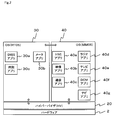
- the vehicle device 1 of the present embodiment is provided with one CPU 3 in the present embodiment on one hardware 2.
- the CPU 3 has a plurality of cores 3a built-in, and in the present embodiment, eight cores 3a are built-in. As shown in FIG. 2 described later, each core 3a is appropriately assigned to operating systems 30 and 40 operating on the CPU 3.
- the number of cores 3a is an example and is not limited to this.
- the CPU 3 can set a rated state in which it operates at a rated operating clock and a high-speed state in which it can operate at a speed higher than the rated operating clock.
- the CPU 3 is provided with a setting unit 3b realized by software.
- the setting unit 3b sets the CPU 3 to either the rated state or the high-speed state.
- the CPU3 When the CPU3 is set to the rated state, it operates only at the rated operating clock. On the other hand, when the CPU 3 is set to the high speed state, the CPU 3 operates while changing the operating clock between the rated operating clock and the maximum allowable clock according to the load. At this time, the CPU 3 is configured such that the operating clock automatically fluctuates according to the load.
- the CPU 3 having a configuration in which one of the operating clocks set in advance between the rated clock and the maximum clock in a plurality of stages is selected according to the load is adopted.
- one that can operate at an arbitrary operating clock between the rated clock and the maximum clock can also be used.
- a radio tuner 4 a video input unit 5, a Global Navigation Satellite System module 6 (hereinafter, GNSS module 6), a communication interface 7 (hereinafter, communication IF 7), a TV tuner 8, and a Data Communication Module 8 (hereinafter, communication IF 7)
- DCM9 Data Communication Module 8
- audio output unit 10 video output unit 11, storage unit 12, Controller Area Network interface 13 (hereinafter, CANIF 13) and the like are provided.
- the vehicle device 1 does not necessarily have all the configurations shown in FIG. 1, and may have the necessary configurations.
- these are also referred to as peripheral circuits for convenience.
- peripheral circuits constitute a functional unit controlled by the CPU 3.
- the radio tuner 4 enables viewing of radio broadcasting by receiving radio waves transmitted from a broadcasting station with an antenna.
- the image input unit 5 inputs images taken by a rear camera 14 provided at the rear of the vehicle and photographing the rear, and a door camera 15 provided at the door of the vehicle and photographing the sides and the rear.
- the video input unit 5 performs processing such as converting the input video into a format that can be processed by the CPU 3 or the like.
- the number and functions of the cameras are merely examples, and the present invention is not limited to this, and a configuration in which a camera substituting a so-called rearview mirror is provided or a configuration in which a door camera 15 is not provided may be provided.
- the GNSS module 6 receives a signal from the artificial satellite of the global positioning satellite system.
- This GNSS module 6 has specifications corresponding to the target system among various systems such as Global Positioning System, GLObal NAvigation Satellite System, Galileo, Quasi-Zenith Satellite System, and BeiDou Navigation Satellite System.
- Communication IF7 is an interface for exchanging data with a storage medium or an external device such as USB, Bluetooth, and Wifi.
- the TV tuner 8 enables the user to watch a TV program by receiving the radio wave transmitted from the broadcasting station with the antenna.
- the DCM9 is a data communication device for a vehicle, and communicates with a center provided outside the vehicle or with another Electronic Control Unit 16 (hereinafter, ECU 16) provided in the vehicle. ..
- ECU 16 Electronic Control Unit 16
- the vehicle device 1 can be considered as one of the ECU 16, the two are distinguished here for the sake of simplification of the description.
- the DCM9 sends vehicle information collected from the ECU 16 to an external center via a network, receives information from the center and notifies the user, and automatically connects to the center in the unlikely event of an accident. It tells the location and time when the accident occurred.
- the audio output unit 10 outputs audio from a radio broadcast, a television broadcast, a navigation function, or the like to the speaker.
- the video output unit 11 displays and outputs a video captured by the rear camera 14 and the door camera 15, a video of a television broadcast, a video read from an external medium, and the like. In addition, the video output unit 11 also displays and outputs the operating state of the vehicle device 1 and the acquired vehicle information.
- the vehicle device 1 is configured to display, for example, a speed meter, a warning light, or the like in full graphic. Then, the image of the speed meter and the image of the warning lamp output from the video output unit 11 are displayed on the meter display 17 as a display unit arranged in front of the driver's seat, for example. Further, the navigation screen is displayed on the center display 18 as a display unit arranged near the center of the vehicle, for example.
- the number and arrangement of display units are examples, and are not limited to these.
- the storage unit 12 is composed of, for example, a semiconductor memory, and stores various data and programs required for the operation of the vehicle device 1. Although the details will be described later, when the vehicle device 1 is started, the boot loader is read from the storage unit 12 and executed, and at that time, the state of the CPU 3 is set. That is, the boot loader stored in the storage unit 12 is executed by the CPU 3, so that the setting unit 3b is realized by software.
- the CANIF 13 is an interface for exchanging data with various ECUs 16 via the CAN bus 19.
- the CANIF 13 operates even when the CPU 3 is not started, and is configured to start the CPU 3 when a start signal (S) is input via the CAN bus 19. Since the CAN bus 19 is originally designed for vehicles and has high noise resistance, it is excluded from the functional parts and peripheral circuits affected by noise in the present embodiment.
- the start signal (S) is a vehicle device from the ECU 16 that detects unlocking operation from the remote control key, opening the door, turning on the accessory switch, turning on the ignition switch, turning on the power switch, and the like. It is transmitted for 1.
- the factors for transmitting the activation signal (S) are not limited to these.
- the hypervisor 20 operates on the hardware 2, that is, on the CPU 3.
- the hypervisor 20 is software for constructing a virtual environment, and a well-known one can be adopted. Therefore, detailed description of the hypervisor 20 will be omitted here.
- the hypervisor 20 may be implemented as a part of the function of the OS, for example.
- the hypervisor 20 is also referred to as an HV for convenience.
- OS30 operating systems 30
- OS40 operating system 40
- the OS 30 is a so-called RealTime OS, and by executing various programs, it realizes a function mainly required for real-time performance.
- the GNSS application 30a for example, the GNSS application 30a for acquiring the current position and time from the information received by the GNSS module 6, the meter application 30b for displaying the image of the speed meter on the meter display 17, and the time application for displaying the time on the center display 18. 30c and the like are executed. Then, each functional unit is realized by each application and the peripheral circuit corresponding to each application.
- the number and types of applications are examples, and are not limited to these.
- the OS 30 is also referred to as a Real Time OS (hereinafter, RTOS) for convenience.
- RTOS Real Time OS
- OS40 realizes functions that do not require real-time performance compared to OS30 and so-called multimedia functions.
- the OS 40 provides a so-called in-vehicle infotainment function that provides information and entertainment.
- OS40 is also referred to as MultiMedia OS (hereinafter, MMOS) for convenience.
- MMOS MultiMedia OS
- the OS 40 communicates with a storage medium or an external device via, for example, an HMI application 40a that provides a human machine interface (hereinafter, HMI), a video application 40b that displays a video input to a video input unit 5, and a communication IF7.
- Communication app 40c to perform, radio app 40d to watch radio broadcast received by radio tuner 4, TV app 40e to watch TV broadcast received by TV tuner 8, DCM app 40f to control DCM9, navigation app to provide navigation function 40g and the like are executed. Then, each functional unit is realized by each application and the peripheral circuit corresponding to each application.
- the number and types of applications are examples, and are not limited to these.
- the hypervisor 20 and the OS30 and OS40, and the OS30 and the OS40 are configured to be communicable by a predetermined protocol. Further, the access from the OS 30 and the OS 40 to the hardware 2 is basically performed via the hypervisor 20.
- the vehicle device 1 is provided with relatively noise-sensitive functional parts such as a radio tuner 4, a GNSS module 6, or a communication IF7 such as Wifi or Bluetooth as described above.
- the vehicle device 1 is required to have a strict noise design so as not to affect them. This is because if noise generated during the operation of the CPU 3 affects the functional unit, it may cause malfunction such as deterioration of voice, misalignment of the vehicle, communication error with another vehicle device 1, and deterioration of the performance of the functional unit. Is.
- variable CPU if the operating clock fluctuates during operation, the noise component also fluctuates accordingly. Considering the verification man-hours and costs, it is practically difficult to design noise for all the operating clocks that the variable CPU can take.
- the vehicle device 1 displays a speed meter image, a warning lamp, etc. as described above. Since these displays are information that is required not only during traveling but also when starting traveling, it is necessary to display them promptly. In addition, for example, there are laws and regulations such as the Kid's Transportation Law (hereinafter referred to as the KT Law) in the United States of America, which stipulate rear visibility requirements including the time until the image of the rear camera 14 is displayed.
- the Kid's Transportation Law hereinafter referred to as the KT Law
- the performance of the vehicle device 1 is improved without affecting the functional unit and the ECU 16 as follows.
- the start of the vehicle device 1 to the operation.
- the time has been shortened. Note that not affecting noise does not mean that noise does not occur at all, but that noise design can be used as a countermeasure.
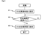
- the vehicle device 1 determines in step S2 whether a predetermined period has elapsed from the start. This predetermined period will be described later. Then, when it is determined that the predetermined period has not elapsed, the vehicle device 1 becomes NO in step S2 and stands by without changing the setting of the CPU 3. Here, the setting change of the CPU 3 is awaited, and the startup process itself is executed by the CPU 3 in the high-speed state.
- step S2 becomes YES, and the CPU 3 is set to the rated state in step S3. Then, the vehicle device 1 ends the setting process of the CPU 3. That is, at the time of startup, the vehicle device 1 sets the CPU 3 to the high-speed state within a predetermined period from the start, and sets the CPU 3 to the rated state after the predetermined period elapses.
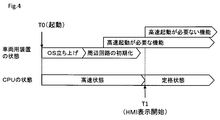
- the state of the vehicle device 1 changes when it is started, as shown in FIG. 4 in a sequence chart with the horizontal axis as the time axis.
- the OS is started and then the peripheral circuits are initialized. After that, the functions that require high-speed start are prioritized, and the functions that do not require high-speed start are also executed.
- the OS startup, peripheral circuit initialization, and execution of each function may be partially duplicated.
- the function that requires high-speed start is a function that is required during traveling and a function that provides information to be notified before starting traveling, and in the present embodiment, the door camera 15 or the like.
- the display of the image taken by the rear camera 14, the display of the speed meter image, the display of the image of the warning lamp, and the like are supported.
- These functions that require high-speed startup are executed at any time when the initialization of the corresponding peripheral circuit is completed.
- the defrost function and the air conditioner function can be considered as functions that require high-speed startup.
- the functions that do not require high-speed startup are those other than those that require high-speed startup, and in the present embodiment, they correspond to viewing radio broadcasts and television broadcasts.
- functions that do not require high-speed startup include functions that are not automatically executed at startup and functions that are started by user operations.
- the CPU 3 is set to a high-speed state in which it operates with a high-speed operation clock. As a result, it is possible to improve the processing capacity at the time of starting, shortening the starting time of the vehicle device 1, that is, achieving high performance, and not affecting the noise caused by the fluctuation of the operating clock. It is possible to achieve both the state and the state.
- the noise does not affect the radio tuner 4.
- the noise does not affect the GNSS module 6 unless the current position of the vehicle is displayed.
- the CPU 3 is set to the high-speed state in the period until the HMI display is started at the time T1. That is, the vehicle device 1 sets the CPU 3 to a high-speed state until the information is visually or audibly provided to the user.
- the HMI is an application that runs on the CPU 3, and constitutes a functional unit controlled by the CPU 3. Therefore, the period from the start to the start of the HMI display is the period from the start to the execution of the specific application running on the CPU 3, and the period from the start to the start of the operation of the specific functional unit. Is also equivalent to. Note that identification can be considered to be sensitive to noise.
- the vehicle device 1 sets the CPU 3 to the rated state. As a result, since the CPU 3 operates at the rated clock after that, the influence of noise due to the fluctuation of the operating clock is eliminated.
- the vehicle device 1 sets the CPU 3 that can set a rated state that operates at the rated operating clock and a high-speed state that can operate at a speed higher than the rated operating clock, and sets the CPU 3 to either the rated state or the high-speed state.
- the setting unit 3b is provided with a setting unit 3b for setting the CPU 3 to a high-speed state within a predetermined period from the start, and sets the CPU 3 to a rated state after the predetermined period elapses.
- the processing capacity of the CPU 3 can be improved at the time of startup, which is considered to have a relatively high load, and the performance of the vehicle device 1 can be improved. Since it is considered that each functional unit and the other vehicle device 1 are also being activated at the time of activation, it is possible to prevent malfunction and performance deterioration due to noise.
- the noise design and evaluation man-hours can be improved without changing the performance, it is possible to achieve both high performance and reliability. Further, if the vehicle device 1 is started quickly, for example, the screen display is started immediately after the user gets on the vehicle, and it is possible to appeal that the vehicle has high performance in a form that is easy for the user to understand.
- the vehicle device 1 sets the CPU 3 to a high-speed state during the period from the start-up to the start of the provision of the human-machine interface. That is, the vehicle device 1 sets the CPU 3 to a high-speed state in the period from the start to the execution of the HMI, which is a specific application running on the CPU 3. Furthermore, the vehicle device 1 sets the CPU 3 to a high-speed state in the period from the start to the start of the operation of the HMI, which is a specific functional unit.
- the CPU 3 can be put into a high-speed state during the predetermined period. It will be possible. Therefore, the high-speed state can be maintained for a longer period of time, and the processing at the time of startup can be speeded up, that is, the startup time can be further shortened.
- the HMI application 40a is exemplified as a specific application and the HMI is exemplified as a specific functional unit, but other applications and functional units can also be a specific application or a specific functional unit.
- the vehicle device 1 sets the CPU 3 to a high-speed state in a predetermined period from the start to the start of the OS running on the CPU 3.
- the hypervisor 20, OS30, and OS40 operate on the vehicle device 1 as shown in FIG.
- the hypervisor 20, OS30, and OS40 have a configuration in which the hypervisor 20 starts up first, then the OS30 starts up, and finally the OS40 starts up when the OS starts up.
- the vehicle device 1, that is, the setting unit 3b sets the CPU 3 to the high-speed state by setting the period from the start time T0 to the start time T10 of the OS 30 as a predetermined period. can do.
- the OS 30 is in charge of processing the GNSS module 6, and the GNSS module 6 is used by the navigation application 40g of the OS 40. Therefore, by setting the CPU 3 in the rated state and the GNSS module 6 in a state not affected by noise when the OS 30 starts up, it is possible to prevent a problem from occurring even if the GNSS module 6 is used immediately after the OS 40 starts up. , It is possible to prevent malfunction and performance deterioration.
- the vehicle device 1 can set the CPU 3 to the high-speed state by setting the period from the start time T0 to the start time T11 of the OS 40 as a predetermined period.
- the OS 40 provides radio broadcasting and television broadcasting, and it is considered that these functions are started by a user operation. Therefore, by setting the CPU 3 to the rated state when the OS 40 starts up, the radio module and the TV module can be in a state where they are not affected by noise, and no problem occurs no matter when the user operates them. It is possible to prevent malfunction and performance deterioration.
- the vehicle device 1 may set the CPU 3 to the high-speed state by setting the period from the start time T0 to the start time T12 of the hypervisor 20 as a predetermined period. it can.
- the hypervisor 20 provides a virtual device for mediating access from OS 30 or OS 40. Therefore, there are peripheral circuits whose initialization is completed when the hypervisor 20 starts up. In addition, the hypervisor 20 itself may access peripheral circuits.
- the peripheral circuits accessed by the hypervisor 20 can be made unaffected by noise, and malfunction and performance deterioration can be prevented. it can.
- the hypervisor 20 is implemented as a part of the function of the OS 30, for example, the period until the application of the hypervisor 20 is executed, or until the functional unit that realizes the hypervisor 20 is executed.
- the CPU 3 can be put into a high-speed state during the above period.
- the vehicle device 1 sets the CPU 3 to a high-speed state in a predetermined period from the start to the completion of the initialization of the peripheral circuit.
- the peripheral circuits used in OS30 and OS40 can be quickly initialized, and each function can be quickly executed after OS30 and OAB are started.
- the vehicle device 1 can set the CPU 3 to the high-speed state in the period until the initialization of the specific peripheral circuit is completed.
- the specific peripheral circuit for example, a circuit used by a function that requires high-speed startup can be targeted.
- the CPU 3 since the CPU 3 is in the rated state when the function requiring high-speed startup is executed, it is possible to prevent the influence of noise on the function requiring high-speed startup.
- the vehicle device 1 can set the CPU 3 to a high-speed state during the startup of the OS, for example, until the initialization of a specific peripheral circuit is completed on the OS 30 side.
- the image of the rear camera 14, which is a function that requires high-speed startup can be configured to display the CPU 3 as a shortcut. In that case, if the initialization of the video input unit 5 and the video output unit 11 is completed, the display can be performed more quickly without waiting for the completion of the startup of the OS 30 and OS 40. ..
- the rated clock is one is shown, but it is also possible to adopt a clock having a plurality of rated clocks and switching between them. In that case, since the operating clock to be switched is known, it is possible to prevent the noise from affecting by designing the noise for each operating clock in advance.
- control unit and its method described in the present disclosure are realized by a dedicated computer provided by configuring a processor and a memory programmed to execute one or more functions embodied by a computer program. May be done.
- control unit and the method described in the present disclosure may be realized by a dedicated computer provided by configuring a processor with one or more dedicated hardware logic circuits.
- control unit and method thereof described in the present disclosure may be a combination of a processor and memory programmed to perform one or more functions and a processor composed of one or more hardware logic circuits. It may be realized by one or more dedicated computers configured.
- the computer program may be stored in a computer-readable non-transitional tangible recording medium as an instruction executed by the computer.
Landscapes
- Engineering & Computer Science (AREA)
- Theoretical Computer Science (AREA)
- Physics & Mathematics (AREA)
- General Engineering & Computer Science (AREA)
- General Physics & Mathematics (AREA)
- Software Systems (AREA)
- Computer Hardware Design (AREA)
- Mechanical Engineering (AREA)
- Fittings On The Vehicle Exterior For Carrying Loads, And Devices For Holding Or Mounting Articles (AREA)
Abstract
A vehicular device (1) according to an embodiment is provided with a CPU (3) and a setting unit (3b). The CPU (3) can be set to a rated state in which the CPU (3) operates at a rated operation clock or a high speed state in which the CPU (3) is operable at a speed higher than the rated operation clock. The setting unit (3b) sets the CPU (3) to either the rated state or the high speed state. The setting unit (3b) sets the CPU (3) to the high speed state for a predetermined period from activation, and sets the CPU (3) to the rated state after a lapse of the predetermined period.
Description
本出願は、2019年3月13日に出願された日本出願番号2019-045892号に基づくもので、ここにその記載内容を援用する。
This application is based on Japanese Application No. 2019-045892 filed on March 13, 2019, and the contents of the description are incorporated herein by reference.
本開示は、車両用装置に関する。
This disclosure relates to vehicle equipment.
一般的に、コンピュータシステムでは、CPUの動作クロックを高くすることにより高性能化を実現できると考えられる。このとき、例えば特許文献1に記載されているような負荷に応じて動作クロックが変動するCPUを用いることにより、必要に応じて一時的に処理能力を向上させることが可能となり、消費電力と処理能力とのバランスをとりつつ全体的な高性能化を実現することができる。以下、動作中に動作クロックが変動するCPUを、便宜的に変動型CPUと称する。
Generally, in a computer system, it is considered that high performance can be realized by increasing the operating clock of the CPU. At this time, for example, by using a CPU whose operating clock fluctuates according to the load as described in Patent Document 1, it is possible to temporarily improve the processing capacity as needed, and the power consumption and processing can be improved. It is possible to achieve overall high performance while balancing the capabilities. Hereinafter, a CPU whose operating clock fluctuates during operation will be referred to as a variable CPU for convenience.
ところで、車両用装置もCPUによって制御されるコンピュータシステムの1つであると考えられる。ただし、車両用装置の場合には、いわゆるパソコンなどの汎用的なコンピュータシステムとは異なり、変動型CPUを採用すると以下のような問題が発生する。
By the way, the vehicle device is also considered to be one of the computer systems controlled by the CPU. However, in the case of a vehicle device, unlike a general-purpose computer system such as a so-called personal computer, the following problems occur when a variable CPU is adopted.
すなわち、車両には、例えばラジオチューナーやGNSSモジュールあるいはWifiやBluetooth(登録商標)など、ノイズに敏感な機能部が設けられている。また、車両には、複数の車両用装置が設けられている。そのため、機能部や他の車両用装置に対してノイズが影響を与えることを防ぐために、各車両用装置には個々に厳密なノイズ設計が求められる。
That is, the vehicle is provided with noise-sensitive functional parts such as a radio tuner, a GNSS module, Wifi, Bluetooth (registered trademark), and the like. Further, the vehicle is provided with a plurality of vehicle devices. Therefore, in order to prevent noise from affecting the functional unit and other vehicle devices, each vehicle device is required to have a strict noise design individually.
そして、仮に変動型CPUを採用する場合には、動作中に動作クロックが変動するとそれに伴ってノイズ成分も変動するため、変動型CPUが取り得る全ての動作クロックに対してノイズ設計を行う必要がある。しかし、検証の工数や費用を考慮すると、全ての動作クロックを想定した理想的なノイズ設計を行うことは現実的には困難である。そして、そのような理想的なノイズ設計を行わなければ、音声の劣化や車両の位置ずれ、あるいは他の車両用装置との通信エラーなどを引き起こすおそれがある。
If a variable CPU is adopted, if the operating clock fluctuates during operation, the noise component also fluctuates accordingly. Therefore, it is necessary to design noise for all the operating clocks that the variable CPU can take. is there. However, considering the man-hours and costs of verification, it is practically difficult to perform an ideal noise design assuming all operating clocks. If such an ideal noise design is not performed, there is a risk of causing voice deterioration, vehicle misalignment, or communication error with other vehicle devices.
本開示は、以上説明した問題に鑑みてなされたものであって、その目的は、ノイズの影響を与えることなく高性能化を実現できる車両用装置を提供することにある。
The present disclosure has been made in view of the problems described above, and an object of the present disclosure is to provide a vehicle device capable of achieving high performance without being affected by noise.
実施形態の車両用装置は、定格の動作クロックで動作する定格状態と、定格の動作クロックよりも高速であって動作可能な高速状態とを設定可能なCPUと、CPUを定格状態または高速状態のいずれかに設定する設定部と、を備え、設定部は、起動から所定期間においてCPUを高速状態に設定するとともに、所定期間が経過した後はCPUを定格状態に設定する。
The vehicle device of the embodiment has a CPU capable of setting a rated state that operates at a rated operating clock and a high-speed state that can operate at a speed higher than the rated operating clock, and a CPU in a rated state or a high-speed state. The setting unit includes a setting unit to be set to either one, and the setting unit sets the CPU to a high-speed state in a predetermined period from the start, and sets the CPU to a rated state after the predetermined period elapses.
このような構成によれば、起動時には機能部や他の車両用装置も起動中であると考えられるため、ノイズの影響を与えることなく車両用装置の高性能化を実現することができる。また、定格状態に設定すれば動作クロックは変動しないため、他の機能部や周辺回路あるいは他の装置にノイズが影響することを防止できる。
According to such a configuration, it is considered that the functional unit and other vehicle devices are also started at the time of startup, so that the performance of the vehicle device can be improved without being affected by noise. Further, since the operating clock does not fluctuate when the rated state is set, it is possible to prevent noise from affecting other functional parts, peripheral circuits, or other devices.
本開示についての上記目的及びその他の目的、特徴や利点は、添付の図面を参照しながら下記の詳細な記述により、より明確になる。その図面は、
図1は、第1実施形態による車両用装置の電気的構成例を模式的に示す図であり、
図2は、車両用装置のソフトウェア構成例を模式的に示す図であり、
図3は、起動処理の流れを示す図であり、
図4は、車両用装置とCPUの状態を対比して示す図であり、
図5は、第2実施形態による車両用装置とCPUの状態を対比して示す図であり、
図6は、第3実施形態による車両用装置とCPUの状態を対比して示す図その1であり、
図7は、車両用装置とCPUの状態を対比して示す図その2であり、
図8は、車両用装置とCPUの状態を対比して示す図その3である。
The above objectives and other objectives, features and advantages of the present disclosure will be clarified by the following detailed description with reference to the accompanying drawings. The drawing is
FIG. 1 is a diagram schematically showing an example of an electrical configuration of a vehicle device according to the first embodiment. FIG. 2 is a diagram schematically showing a software configuration example of a vehicle device. FIG. 3 is a diagram showing the flow of startup processing. FIG. 4 is a diagram showing the states of the vehicle device and the CPU in comparison with each other. FIG. 5 is a diagram showing the states of the vehicle device and the CPU according to the second embodiment in comparison with each other. FIG. 6 is FIG. 1 for comparing the states of the vehicle device and the CPU according to the third embodiment. FIG. 7 is FIG. 2 showing a comparison between the states of the vehicle device and the CPU. FIG. 8 is FIG. 3 showing a comparison between the states of the vehicle device and the CPU.
以下、複数の実施形態について図面を参照しながら説明する。なお、各実施形態において実質的に共通するものには同一符号を付して説明する。
(第1実施形態)
以下、第1実施形態について、図1から図4を参照しながら説明する。まず、図1を参照しながら車両用装置1の電気的構成について説明する。 Hereinafter, a plurality of embodiments will be described with reference to the drawings. In addition, what is substantially common in each embodiment will be described with the same reference numerals.
(First Embodiment)
Hereinafter, the first embodiment will be described with reference to FIGS. 1 to 4. First, the electrical configuration of thevehicle device 1 will be described with reference to FIG.
(第1実施形態)
以下、第1実施形態について、図1から図4を参照しながら説明する。まず、図1を参照しながら車両用装置1の電気的構成について説明する。 Hereinafter, a plurality of embodiments will be described with reference to the drawings. In addition, what is substantially common in each embodiment will be described with the same reference numerals.
(First Embodiment)
Hereinafter, the first embodiment will be described with reference to FIGS. 1 to 4. First, the electrical configuration of the
図1に示すように、本実施形態の車両用装置1は、1つのハードウェア2上に本実施形態では1つのCPU3が設けられている。このCPU3は、複数のコア3aを内蔵したものであり、本実施形態では8個のコア3aを内蔵している。各コア3aは、後述する図2に示すように、CPU3上で動作するオペレーティングシステム30、40に適宜割り当てられている。なお、コア3aの数は一例であり、これに限定されない。
As shown in FIG. 1, the vehicle device 1 of the present embodiment is provided with one CPU 3 in the present embodiment on one hardware 2. The CPU 3 has a plurality of cores 3a built-in, and in the present embodiment, eight cores 3a are built-in. As shown in FIG. 2 described later, each core 3a is appropriately assigned to operating systems 30 and 40 operating on the CPU 3. The number of cores 3a is an example and is not limited to this.
CPU3は、定格の動作クロックで動作する定格状態と、定格の動作クロックよりも高速で動作可能な高速状態とを設定可能となっている。そして、CPU3には、ソフトウェアで実現された設定部3bが設けられている。この設定部3bは、CPU3を定格状態または高速状態のいずれかに設定する。
The CPU 3 can set a rated state in which it operates at a rated operating clock and a high-speed state in which it can operate at a speed higher than the rated operating clock. The CPU 3 is provided with a setting unit 3b realized by software. The setting unit 3b sets the CPU 3 to either the rated state or the high-speed state.
CPU3は、定格状態に設定されている場合には、定格の動作クロックでのみ動作する。一方、CPU3は、高速状態に設定されている場合には、負荷に応じて、定格の動作クロックと許容される最大クロックとの間で動作クロックを変動させながら動作する。このとき、CPU3は、負荷に応じて動作クロックが自動的に変動する構成となっている。
When the CPU3 is set to the rated state, it operates only at the rated operating clock. On the other hand, when the CPU 3 is set to the high speed state, the CPU 3 operates while changing the operating clock between the rated operating clock and the maximum allowable clock according to the load. At this time, the CPU 3 is configured such that the operating clock automatically fluctuates according to the load.
なお、高速状態であっても負荷によっては定格の動作クロックで動作することもあるため、必ずしも高速状態=動作クロックが変動している状態ということではない。また、本実施形態では、定格クロックと最大クロックとの間で予め複数段階で設定されている動作クロックのうち、いずれかの動作クロックを負荷に応じて選択する構成のCPU3を採用している。ただし、定格クロックと最大クロックとの間の任意の動作クロックで動作可能なものを用いることもできる。
Note that even in the high-speed state, depending on the load, it may operate at the rated operating clock, so the high-speed state = the operating clock does not necessarily fluctuate. Further, in the present embodiment, the CPU 3 having a configuration in which one of the operating clocks set in advance between the rated clock and the maximum clock in a plurality of stages is selected according to the load is adopted. However, one that can operate at an arbitrary operating clock between the rated clock and the maximum clock can also be used.
また、ハードウェア2上には、ラジオチューナー4、映像入力部5、Global Navigation Satellite Systemモジュール6(以下、GNSSモジュール6)、通信インターフェース7(以下、通信IF7)、テレビチューナー8、Data Communication Module8(以下、DCM9)、音声出力部10、映像出力部11、記憶部12、Controller Area Networkインターフェース13(以下、CANIF13)などが設けられている。
Further, on the hardware 2, a radio tuner 4, a video input unit 5, a Global Navigation Satellite System module 6 (hereinafter, GNSS module 6), a communication interface 7 (hereinafter, communication IF 7), a TV tuner 8, and a Data Communication Module 8 (hereinafter, communication IF 7) Hereinafter, DCM9), audio output unit 10, video output unit 11, storage unit 12, Controller Area Network interface 13 (hereinafter, CANIF 13) and the like are provided.
ただし、車両用装置1は、必ずしも図1に示す全ての構成を備えている必要はなく、必要な構成を備えていればよい。以下、これらを便宜的に周辺回路とも称する。また、これらの周辺回路は、CPU3によって制御される機能部を構成する。
ラジオチューナー4は、放送局から送信される電波をアンテナで受信することにより、ラジオ放送の視聴を可能にする。 However, thevehicle device 1 does not necessarily have all the configurations shown in FIG. 1, and may have the necessary configurations. Hereinafter, these are also referred to as peripheral circuits for convenience. Further, these peripheral circuits constitute a functional unit controlled by the CPU 3.
Theradio tuner 4 enables viewing of radio broadcasting by receiving radio waves transmitted from a broadcasting station with an antenna.
ラジオチューナー4は、放送局から送信される電波をアンテナで受信することにより、ラジオ放送の視聴を可能にする。 However, the
The
映像入力部5は、車両の後方に設けられて後方を撮影するリアカメラ14や、車両のドアに設けられて側方および後方を撮影するドアカメラ15により撮影された映像が入力される。映像入力部5は、入力された映像をCPU3等で処理できるフォーマットに変換する等の処理を行う。なお、カメラの数や機能は一例であり、これに限定されず、いわゆるルームミラーを代用するカメラを設ける構成やドアカメラ15を設けない構成とすることもできる。
The image input unit 5 inputs images taken by a rear camera 14 provided at the rear of the vehicle and photographing the rear, and a door camera 15 provided at the door of the vehicle and photographing the sides and the rear. The video input unit 5 performs processing such as converting the input video into a format that can be processed by the CPU 3 or the like. The number and functions of the cameras are merely examples, and the present invention is not limited to this, and a configuration in which a camera substituting a so-called rearview mirror is provided or a configuration in which a door camera 15 is not provided may be provided.
GNSSモジュール6は、全球測位衛星システムの人工衛星から信号を受信する。このGNSSモジュール6は、例えばGlobal Positioning System、GLObal NAvigation Satellite System、Galileo、準天頂衛星システム、BeiDou Navigation Satellite Systemなどの各種の方式のうち、対象となる方式に対応する仕様となっている。
The GNSS module 6 receives a signal from the artificial satellite of the global positioning satellite system. This GNSS module 6 has specifications corresponding to the target system among various systems such as Global Positioning System, GLObal NAvigation Satellite System, Galileo, Quasi-Zenith Satellite System, and BeiDou Navigation Satellite System.
通信IF7は、例えばUSB、Bluetooth、Wifiなど、記憶媒体や外部の装置との間でデータのやり取りを行うインターフェースである。テレビチューナー8は、放送局から送信される電波をアンテナで受信することにより、ユーザにテレビ番組の視聴を可能にする。
Communication IF7 is an interface for exchanging data with a storage medium or an external device such as USB, Bluetooth, and Wifi. The TV tuner 8 enables the user to watch a TV program by receiving the radio wave transmitted from the broadcasting station with the antenna.
DCM9は、車両用のデータ通信装置であり、車両の外部に設けられているセンターとの間、あるいは、車両に設けられている他のElectronic Control Unit16(以下、ECU16)との間で通信を行う。なお、車両用装置1もECU16の1つと考えることはできるものの、ここでは説明の簡略化のために両者を区別している。
The DCM9 is a data communication device for a vehicle, and communicates with a center provided outside the vehicle or with another Electronic Control Unit 16 (hereinafter, ECU 16) provided in the vehicle. .. Although the vehicle device 1 can be considered as one of the ECU 16, the two are distinguished here for the sake of simplification of the description.
このDCM9は、例えばECU16から収集した車両情報をネットワーク経由で外部のセンターに送ったり、センターからの情報を受信してユーザに報知したり、万が一事故が発生した場合には自動でセンターに接続して事故が発生した位置や時刻を伝えたりする。
音声出力部10は、ラジオ放送やテレビ放送あるいはナビゲーション機能などからの音声をスピーカに対して出力する。 For example, the DCM9 sends vehicle information collected from theECU 16 to an external center via a network, receives information from the center and notifies the user, and automatically connects to the center in the unlikely event of an accident. It tells the location and time when the accident occurred.
Theaudio output unit 10 outputs audio from a radio broadcast, a television broadcast, a navigation function, or the like to the speaker.
音声出力部10は、ラジオ放送やテレビ放送あるいはナビゲーション機能などからの音声をスピーカに対して出力する。 For example, the DCM9 sends vehicle information collected from the
The
映像出力部11は、リアカメラ14やドアカメラ15で撮像した映像や、テレビ放送の映像、あるいは外部メディアから読み込んだ映像などを表示出力する。また、映像出力部11は、車両用装置1の動作状態や取得した車両情報などの表示出力も行う。
The video output unit 11 displays and outputs a video captured by the rear camera 14 and the door camera 15, a video of a television broadcast, a video read from an external medium, and the like. In addition, the video output unit 11 also displays and outputs the operating state of the vehicle device 1 and the acquired vehicle information.
本実施形態の場合、車両用装置1は、例えば速度メータや警告灯などをフルグラフィック表示する構成となっている。そして、映像出力部11から出力された速度メータの画像や警告ランプの画像は、例えば運転席の前方に配置されている表示部としてのメータディスプレイ17に表示される。また、ナビゲーション画面は、例えば車両の中央付近に配置されている表示部としてのセンターディスプレイ18に表示される。なお、表示部の数や配置は一例であり、これに限定されない。
In the case of the present embodiment, the vehicle device 1 is configured to display, for example, a speed meter, a warning light, or the like in full graphic. Then, the image of the speed meter and the image of the warning lamp output from the video output unit 11 are displayed on the meter display 17 as a display unit arranged in front of the driver's seat, for example. Further, the navigation screen is displayed on the center display 18 as a display unit arranged near the center of the vehicle, for example. The number and arrangement of display units are examples, and are not limited to these.
記憶部12は、例えば半導体メモリで構成されており、車両用装置1の動作に必要となる各種のデータやプログラムが記憶されている。なお、詳細は後述するが、車両用装置1の起動時には記憶部12からブートローダが読み出されて実行され、その際、CPU3の状態が設定される。つまり、記憶部12に記憶されているブートローダがCPU3で実行されることにより、設定部3bがソフトウェアで実現されている。
The storage unit 12 is composed of, for example, a semiconductor memory, and stores various data and programs required for the operation of the vehicle device 1. Although the details will be described later, when the vehicle device 1 is started, the boot loader is read from the storage unit 12 and executed, and at that time, the state of the CPU 3 is set. That is, the boot loader stored in the storage unit 12 is executed by the CPU 3, so that the setting unit 3b is realized by software.
CANIF13は、CANバス19を経由して各種のECU16との間でデータのやり取りを行うインターフェースである。このCANIF13は、CPU3が起動していない状態でも動作しており、CANバス19を介して起動信号(S)が入力されると、CPU3を起動させる構成となっている。なお、CANバス19は、そもそも車両用に設計されたものであり、対ノイズ性が高いことから、本実施形態で言うノイズの影響を受ける機能部や周辺回路からは除外されるものとする。
The CANIF 13 is an interface for exchanging data with various ECUs 16 via the CAN bus 19. The CANIF 13 operates even when the CPU 3 is not started, and is configured to start the CPU 3 when a start signal (S) is input via the CAN bus 19. Since the CAN bus 19 is originally designed for vehicles and has high noise resistance, it is excluded from the functional parts and peripheral circuits affected by noise in the present embodiment.
起動信号(S)は、例えばリモコンキーからの解錠操作、ドアの開放、アクセサリスイッチのオン、イグニッションスイッチのオン、パワースイッチのオンなどを検知したときに、それらを検知したECU16から車両用装置1に対して送信される。なお、起動信号(S)が送信される要因はこれらに限定されない。
The start signal (S) is a vehicle device from the ECU 16 that detects unlocking operation from the remote control key, opening the door, turning on the accessory switch, turning on the ignition switch, turning on the power switch, and the like. It is transmitted for 1. The factors for transmitting the activation signal (S) are not limited to these.
次に、図2を参照しながら車両用装置1のソフトウェア構成について説明する。図2に示すように、車両用装置1は、ハードウェア2上つまりはCPU3上で、ハイパーバイザ20が動作する。このハイパーバイザ20は、仮想化環境を構築するためのソフトウェアであり、周知のものを採用することができる。そのため、ここではハイパーバイザ20の詳細な説明は省略する。なお、ハイパーバイザ20は、例えばOSの機能の一部として実装されるものであってもよい。以下、ハイパーバイザ20を便宜的にHVとも称する。
Next, the software configuration of the vehicle device 1 will be described with reference to FIG. As shown in FIG. 2, in the vehicle device 1, the hypervisor 20 operates on the hardware 2, that is, on the CPU 3. The hypervisor 20 is software for constructing a virtual environment, and a well-known one can be adopted. Therefore, detailed description of the hypervisor 20 will be omitted here. The hypervisor 20 may be implemented as a part of the function of the OS, for example. Hereinafter, the hypervisor 20 is also referred to as an HV for convenience.
このハイパーバイザ20上では、複数ここではオペレーティングシステム30(以下、OS30)とオペレーティングシステム40(以下、OS40)との2つが動作する。OS30は、いわゆるReal Time OSであり、各種のプログラムを実行することにより、主としてリアルタイム性能が要求される機能を実現する。
On this hypervisor 20, a plurality of operating systems 30 (hereinafter, OS30) and operating system 40 (hereinafter, OS40) are operated. The OS 30 is a so-called RealTime OS, and by executing various programs, it realizes a function mainly required for real-time performance.
以下、OS30ならびにOS40上で実行される各種のプログラムを、便宜的にアプリケーションと総称する。また、個別のアプリケーションについては、例えば後述するように映像アプリ40bなどとも称する。
Hereinafter, various programs executed on OS30 and OS40 are collectively referred to as applications for convenience. Further, the individual application is also referred to as a video application 40b or the like, as will be described later.
OS30では、例えばGNSSモジュール6で受信した情報から現在位置や時刻を取得するためのGNSSアプリ30a、メータディスプレイ17に速度メータの画像を表示するメータアプリ30b、センターディスプレイ18に時刻を表示する時刻アプリ30cなどが実行される。そして、各アプリケーションとそれに対応する周辺回路とによって、それぞれの機能部が実現されている。なお、アプリケーションの数や種類は一例であり、これらに限定されない。以下、OS30を便宜的にReal Time OS(以下、RTOS)とも称する。
In OS30, for example, the GNSS application 30a for acquiring the current position and time from the information received by the GNSS module 6, the meter application 30b for displaying the image of the speed meter on the meter display 17, and the time application for displaying the time on the center display 18. 30c and the like are executed. Then, each functional unit is realized by each application and the peripheral circuit corresponding to each application. The number and types of applications are examples, and are not limited to these. Hereinafter, the OS 30 is also referred to as a Real Time OS (hereinafter, RTOS) for convenience.
OS40は、OS30に比べてリアルタイム性が要求されない機能や、いわゆるマルチメディア系の機能を実現する。このOS40により、情報の提供と娯楽の提供とを行ういわゆる車載インフォテイメント機能が提供されている。以下、OS40を便宜的にMulti Media OS(以下、MMOS)とも称する。
OS40 realizes functions that do not require real-time performance compared to OS30 and so-called multimedia functions. The OS 40 provides a so-called in-vehicle infotainment function that provides information and entertainment. Hereinafter, OS40 is also referred to as MultiMedia OS (hereinafter, MMOS) for convenience.
このOS40では、例えばヒューマンマシンインターフェース(以下、HMI)を提供するHMIアプリ40a、映像入力部5に入力された映像を表示する映像アプリ40b、通信IF7を介して記憶媒体や外部の装置と通信を行う通信アプリ40c、ラジオチューナー4で受信したラジオ放送を視聴するラジオアプリ40d、テレビチューナー8で受信したテレビ放送を視聴するテレビアプリ40e、DCM9を制御するDCMアプリ40f、ナビゲーション機能を提供するナビアプリ40gなどが実行される。そして、各アプリケーションとそれに対応する周辺回路とによって、それぞれの機能部が実現されている。なお、アプリケーションの数や種類は一例であり、これらに限定されない。
The OS 40 communicates with a storage medium or an external device via, for example, an HMI application 40a that provides a human machine interface (hereinafter, HMI), a video application 40b that displays a video input to a video input unit 5, and a communication IF7. Communication app 40c to perform, radio app 40d to watch radio broadcast received by radio tuner 4, TV app 40e to watch TV broadcast received by TV tuner 8, DCM app 40f to control DCM9, navigation app to provide navigation function 40g and the like are executed. Then, each functional unit is realized by each application and the peripheral circuit corresponding to each application. The number and types of applications are examples, and are not limited to these.
これらハイパーバイザ20とOS30、OS40との間、ならびにOS30とOS40との間は、所定のプロトコルで通信可能に構成されている。また、OS30、OS40からハードウェア2へのアクセスは、基本的にはハイパーバイザ20を経由して行われる。
The hypervisor 20 and the OS30 and OS40, and the OS30 and the OS40 are configured to be communicable by a predetermined protocol. Further, the access from the OS 30 and the OS 40 to the hardware 2 is basically performed via the hypervisor 20.
次に、上記した構成の作用について説明する。
前述のように、一般的なコンピュータシステムであれば動作クロックを高くすることにより高性能化を実現することができると考えられる。このとき、単純に動作クロックを高くするとオーバースペックになる可能性があることから、動作中に動作クロックを変動可能な変動型CPUを用いれば、消費電力と処理能力とのバランスをとりつつ全体的な高性能化を実現することができると考えられる。 Next, the operation of the above configuration will be described.
As described above, in a general computer system, it is considered that high performance can be realized by increasing the operating clock. At this time, if the operating clock is simply increased, over-specification may occur. Therefore, if a variable CPU that can change the operating clock during operation is used, the overall power consumption and processing capacity are balanced. It is thought that high performance can be achieved.
ただし、車両用装置1の場合には、上記したようにラジオチューナー4やGNSSモジュール6、あるいはWifiやBluetoothのような通信IF7など、比較的ノイズに敏感な機能部を備えている。そして、車両用装置1にはそれらに影響を与えないように厳密なノイズ設計が求められている。これは、CPU3の動作時に生じるノイズが機能部に影響すると、音声の劣化や車両の位置ずれ、あるいは他の車両用装置1との通信エラーといった誤動作や機能部の性能劣化を引き起こすおそれがあるためである。
However, the vehicle device 1 is provided with relatively noise-sensitive functional parts such as a radio tuner 4, a GNSS module 6, or a communication IF7 such as Wifi or Bluetooth as described above. The vehicle device 1 is required to have a strict noise design so as not to affect them. This is because if noise generated during the operation of the CPU 3 affects the functional unit, it may cause malfunction such as deterioration of voice, misalignment of the vehicle, communication error with another vehicle device 1, and deterioration of the performance of the functional unit. Is.
しかし、変動型CPUは、動作中に動作クロックが変動するとそれに伴ってノイズ成分も変動する。そして、検証の工数や費用を考慮すると、変動型CPUが取り得る全ての動作クロックに対してノイズ設計を行うことは、現実的には困難である。
However, in the variable CPU, if the operating clock fluctuates during operation, the noise component also fluctuates accordingly. Considering the verification man-hours and costs, it is practically difficult to design noise for all the operating clocks that the variable CPU can take.
そのため、従来では、動作クロックを変動させないことにより、ノイズ設計を容易に行えるようにしていた。これは、車両用装置1の場合には実行されるOSやアプリケーションがある程度想定できることから、それらの動作に十分な性能のCPU3が予め採用されており、いわゆるパソコンのような汎用的な一般的なコンピュータシステムと比べると動作中に動作クロックを変動させる状況が発生し難いという車両用装置1の性質にも起因している。
Therefore, in the past, noise design was made easy by not changing the operating clock. This is because in the case of the vehicle device 1, the OS and applications to be executed can be assumed to some extent, so that the CPU 3 having sufficient performance for their operation is adopted in advance, and it is a general-purpose general-purpose computer such as a so-called personal computer. This is also due to the nature of the vehicle device 1 that it is less likely that the operating clock will fluctuate during operation as compared with a computer system.
換言すると、車両用装置1の場合には、変動型CPUを用いるメリットがそれほどなく、逆に、変動型CPUを用いることでノイズ設計が困難になるというデメリットが存在していた。
In other words, in the case of the vehicle device 1, there is not much merit of using the variable CPU, and conversely, there is a demerit that noise design becomes difficult by using the variable CPU.
その一方で、車両用装置1は、上記したように速度メータ画像や警告ランプなどを表示する。これらの表示は、走行中だけでなく、走行を開始する際にも必要とされる情報であるため、迅速に表示する必要がある。また、例えばアメリカ合衆国におけるKid's Transportation法(以下、KT法)のように、リアカメラ14の画像が表示されるまでの時間などを含む後方視認要件を規定する法規も存在している。
On the other hand, the vehicle device 1 displays a speed meter image, a warning lamp, etc. as described above. Since these displays are information that is required not only during traveling but also when starting traveling, it is necessary to display them promptly. In addition, for example, there are laws and regulations such as the Kid's Transportation Law (hereinafter referred to as the KT Law) in the United States of America, which stipulate rear visibility requirements including the time until the image of the rear camera 14 is displayed.
そのため、車両用装置1の高性能化が強く求められている。ただし、上記したように、機能部やECU16に影響を与えないことが必須の条件となっている。そこで、本実施形態では、以下のようにして機能部やECU16にノイズの影響を与えることなく、車両用装置1の高性能化ここでは車両用装置1が起動してから動作可能になるまでの時間の短縮化を実現している。なお、ノイズの影響を与えないとは、ノイズが全く発生しないということではなく、ノイズ設計によって対策できるということを意味している。
Therefore, there is a strong demand for higher performance of the vehicle device 1. However, as described above, it is an essential condition that the functional unit and the ECU 16 are not affected. Therefore, in the present embodiment, the performance of the vehicle device 1 is improved without affecting the functional unit and the ECU 16 as follows. Here, from the start of the vehicle device 1 to the operation. The time has been shortened. Note that not affecting noise does not mean that noise does not occur at all, but that noise design can be used as a countermeasure.
まず、図3を参照しながら、起動時の処理の流れについて説明する。なお、CPU3の状態の設定は設定部3bによって行われるものの、説明の簡略化のため、以下では車両用装置1を主体として説明する。
First, the flow of processing at startup will be described with reference to FIG. Although the state of the CPU 3 is set by the setting unit 3b, the vehicle device 1 will be mainly described below for simplification of the description.
車両用装置1は、図3に示す起動処理において、起動信号(S)が入力されて起動されると、ステップS1においてCPU3を高速状態に設定する。この設定は、記憶部12から読み出されたブートローダが実行されるときに行われる。つまり、CPU3は、起動後に迅速に高速状態に移行する。
When the vehicle device 1 is activated by inputting the activation signal (S) in the activation process shown in FIG. 3, the CPU 3 is set to the high speed state in step S1. This setting is performed when the boot loader read from the storage unit 12 is executed. That is, the CPU 3 quickly shifts to the high-speed state after startup.
続いて、車両用装置1は、ステップS2において起動から所定期間が経過したかを判断する。この所定期間については後述する。そして、車両用装置1は、所定期間が経過していないと判断した場合には、ステップS2でNOとなり、CPU3の設定変更を行わずに待機する。なお、ここではCPU3の設定変更を待機しているのであって、起動処理そのものは高速状態のCPU3によって実行されることになる。
Subsequently, the vehicle device 1 determines in step S2 whether a predetermined period has elapsed from the start. This predetermined period will be described later. Then, when it is determined that the predetermined period has not elapsed, the vehicle device 1 becomes NO in step S2 and stands by without changing the setting of the CPU 3. Here, the setting change of the CPU 3 is awaited, and the startup process itself is executed by the CPU 3 in the high-speed state.
一方、車両用装置1は、所定期間が経過したと判断した場合には、ステップS2がYESとなり、ステップS3においてCPU3を定格状態に設定する。そして、車両用装置1は、CPU3の設定処理を終了する。つまり、車両用装置1は、起動時に、起動から所定期間においてCPU3を高速状態に設定するとともに、所定期間が経過するとCPU3を定格状態に設定する処理を行っている。
On the other hand, when the vehicle device 1 determines that the predetermined period has elapsed, step S2 becomes YES, and the CPU 3 is set to the rated state in step S3. Then, the vehicle device 1 ends the setting process of the CPU 3. That is, at the time of startup, the vehicle device 1 sets the CPU 3 to the high-speed state within a predetermined period from the start, and sets the CPU 3 to the rated state after the predetermined period elapses.
次に、上記した所定期間の詳細について説明する。車両用装置1は、図4に横軸を時間軸としたシーケンスチャートで示すように、起動時にその状態が変化する。車両用装置1は、起動するとOSの立ち上げが行われた後、周辺回路の初期化が行われ、その後、高速起動が必要な機能を優先しつつ、高速起動が必要ない機能についても実行される。なお、OSの立ち上げや周辺回路の初期化および各機能の実行は、一部重複して行われることもある。
Next, the details of the above-mentioned predetermined period will be described. The state of the vehicle device 1 changes when it is started, as shown in FIG. 4 in a sequence chart with the horizontal axis as the time axis. When the vehicle device 1 is started, the OS is started and then the peripheral circuits are initialized. After that, the functions that require high-speed start are prioritized, and the functions that do not require high-speed start are also executed. To. The OS startup, peripheral circuit initialization, and execution of each function may be partially duplicated.
ここで、高速起動が必要な機能とは、走行中に必要とされる機能、および、走行を開始する前に通知すべき情報を提供する機能であり、本実施形態で言えばドアカメラ15やリアカメラ14で撮影した映像の表示、速度メータ画像の表示、警告ランプの画像の表示などが対応する。これら高速起動が必要な機能は、対応する周辺回路の初期化が完了すると随時実行される。また、ユーザの利便性に鑑みれば、図示は省略するがデフロスト機能やエアコン機能も高速起動が必要な機能に含めて考えることもできる。
Here, the function that requires high-speed start is a function that is required during traveling and a function that provides information to be notified before starting traveling, and in the present embodiment, the door camera 15 or the like. The display of the image taken by the rear camera 14, the display of the speed meter image, the display of the image of the warning lamp, and the like are supported. These functions that require high-speed startup are executed at any time when the initialization of the corresponding peripheral circuit is completed. Further, from the viewpoint of user convenience, although not shown, the defrost function and the air conditioner function can be considered as functions that require high-speed startup.
一方、高速起動が必要ない機能とは、高速起動が必要な機能以外のものであり、本実施形態で言えば、ラジオ放送やテレビ放送の視聴などが対応する。また、高速起動が必要ない機能としては、起動時に自動的に実行されない機能や、ユーザの操作によって開始される機能なども含まれる。
On the other hand, the functions that do not require high-speed startup are those other than those that require high-speed startup, and in the present embodiment, they correspond to viewing radio broadcasts and television broadcasts. In addition, functions that do not require high-speed startup include functions that are not automatically executed at startup and functions that are started by user operations.
このように、車両用装置1の起動時にはOSの立ち上げや様々な初期化の処理を実行する必要があり、初期化が完了した後のいわゆる通常状態よりも負荷が大きくなることが想定される。そのため、車両用装置1の高性能化を実現するためには、起動時間の短縮化の優先度が高くなってくる。
In this way, when the vehicle device 1 is started, it is necessary to start the OS and execute various initialization processes, and it is expected that the load will be larger than the so-called normal state after the initialization is completed. .. Therefore, in order to realize high performance of the vehicle device 1, the priority of shortening the start-up time is high.
また、起動した直後では一部の機能すなわち高速起動が必要な機能を迅速に実行する必要があるものの、高速起動が必要ない機能は一定時間が経過した後に実行されればよいことが多い。さらに、車両用装置1が起動するタイミングでは、他のECU16も起動中であると考えられる。
In addition, although it is necessary to quickly execute some functions, that is, functions that require high-speed startup immediately after startup, it is often sufficient to execute functions that do not require high-speed startup after a certain period of time has passed. Further, it is considered that the other ECU 16 is also being activated at the timing when the vehicle device 1 is activated.
そこで、これらの点に着目し、車両用装置1の起動時に、CPU3を高速な動作クロックで動作する高速状態に設定している。これにより、起動時の処理能力を向上させることが可能となり、車両用装置1の起動時間の短縮化つまりは高性能化の実現と、動作クロックが変動することに起因するノイズの影響を与えない状態にすることとを、両立させることができる。
Therefore, paying attention to these points, when the vehicle device 1 is started, the CPU 3 is set to a high-speed state in which it operates with a high-speed operation clock. As a result, it is possible to improve the processing capacity at the time of starting, shortening the starting time of the vehicle device 1, that is, achieving high performance, and not affecting the noise caused by the fluctuation of the operating clock. It is possible to achieve both the state and the state.
ところで、本実施形態では、ノイズの影響を与えない状態として、文字通り機能部の周辺回路などにノイズが影響しない状態だけでなく、ノイズの影響があってもそれが車両用機器の性能や信頼性に直接的な影響を及ぼさない状態も含めている。
By the way, in the present embodiment, as a state in which noise does not affect, not only a state in which noise does not literally affect the peripheral circuits of functional parts, but also a state in which noise does affect the performance and reliability of vehicle equipment. It also includes a state that does not directly affect the noise.
例えば、ラジオチューナー4にノイズが影響して音質が劣化したとしても、音声が出力されていなければ、ノイズの影響は及んでいないと考えることができる。あるいは、GNSSモジュール6にノイズが影響して現在位置を特定できないとしても、車両の現在位置の表示が行われていなければ、ノイズの影響は及んでいないと考えることもできる。
For example, even if noise affects the radio tuner 4 and the sound quality deteriorates, if no sound is output, it can be considered that the noise does not affect the radio tuner 4. Alternatively, even if the GNSS module 6 is affected by noise and the current position cannot be specified, it can be considered that the noise does not affect the GNSS module 6 unless the current position of the vehicle is displayed.
そして、ノイズの影響が及んでいないと考えることができる期間が長いほど、処理能力が向上している高速状態の期間も長くなり、車両用装置1をより高性能化することができると考えられる。
It is considered that the longer the period during which it can be considered that the influence of noise is not exerted, the longer the period during the high-speed state in which the processing capacity is improved, and the higher the performance of the vehicle device 1 can be considered. ..
そこで、車両用装置1は、図4に示す時刻T0において起動したとすると、時刻T1においてHMIの表示が開始されるまでの期間において、CPU3を高速状態に設定している。つまり、車両用装置1は、ユーザに視覚的または聴覚的に情報の提供が開始するまでの期間、CPU3を高速状態に設定している。
Therefore, assuming that the vehicle device 1 is started at the time T0 shown in FIG. 4, the CPU 3 is set to the high-speed state in the period until the HMI display is started at the time T1. That is, the vehicle device 1 sets the CPU 3 to a high-speed state until the information is visually or audibly provided to the user.
これにより、高速状態をより長く維持することができ、起動時間をより一層短縮化することができる。なおHMIは、CPU3上で動作するアプリケーションであるとともに、CPU3によって制御される機能部を構成している。そのため、HMIの表示が開始されるまでの期間とは、起動からCPU3上で動作する特定のアプリケーションが実行されるまでの期間、ならびに、起動から特定の機能部の動作が開始されるまでの期間にも相当する。なお、特定とは、ノイズに敏感なものと考えることができる。
As a result, the high-speed state can be maintained for a longer period of time, and the startup time can be further shortened. The HMI is an application that runs on the CPU 3, and constitutes a functional unit controlled by the CPU 3. Therefore, the period from the start to the start of the HMI display is the period from the start to the execution of the specific application running on the CPU 3, and the period from the start to the start of the operation of the specific functional unit. Is also equivalent to. Note that identification can be considered to be sensitive to noise.
その後、車両用装置1は、CPU3を定格状態に設定する。これにより、それ以降はCPU3が定格クロックで動作することから、動作クロックの変動に伴うノイズの影響は排除される。
After that, the vehicle device 1 sets the CPU 3 to the rated state. As a result, since the CPU 3 operates at the rated clock after that, the influence of noise due to the fluctuation of the operating clock is eliminated.
以上説明した車両用装置1によれば、次のような効果を得ることができる。
車両用装置1は、定格の動作クロックで動作する定格状態と、定格の動作クロックよりも高速で動作可能な高速状態とを設定可能なCPU3と、CPU3を定格状態または高速状態のいずれかに設定する設定部3bと、を備え、設定部3bは、起動から所定期間においてCPU3を高速状態に設定するとともに、所定期間が経過した後にはCPU3を定格状態に設定する。 According to thevehicle device 1 described above, the following effects can be obtained.
Thevehicle device 1 sets the CPU 3 that can set a rated state that operates at the rated operating clock and a high-speed state that can operate at a speed higher than the rated operating clock, and sets the CPU 3 to either the rated state or the high-speed state. The setting unit 3b is provided with a setting unit 3b for setting the CPU 3 to a high-speed state within a predetermined period from the start, and sets the CPU 3 to a rated state after the predetermined period elapses.
車両用装置1は、定格の動作クロックで動作する定格状態と、定格の動作クロックよりも高速で動作可能な高速状態とを設定可能なCPU3と、CPU3を定格状態または高速状態のいずれかに設定する設定部3bと、を備え、設定部3bは、起動から所定期間においてCPU3を高速状態に設定するとともに、所定期間が経過した後にはCPU3を定格状態に設定する。 According to the
The
このような構成によれば、比較的負荷が高いと考えられる起動時にCPU3の処理能力を向上させることができ、車両用装置1の高性能化を実現することができる。そして、起動時には各機能部や他の車両用装置1も起動中であると考えられるため、ノイズによる誤動作や性能劣化を防止することができる。
According to such a configuration, the processing capacity of the CPU 3 can be improved at the time of startup, which is considered to have a relatively high load, and the performance of the vehicle device 1 can be improved. Since it is considered that each functional unit and the other vehicle device 1 are also being activated at the time of activation, it is possible to prevent malfunction and performance deterioration due to noise.
したがって、ノイズの影響を与えることなく高性能化を実現することができる。換言すると、高速状態ではノイズ耐性の高い機能を動作させることにより、ノイズによる誤動作や性能劣化への影響を排除することができる。
Therefore, high performance can be realized without being affected by noise. In other words, by operating a function with high noise immunity in the high-speed state, it is possible to eliminate the influence of noise on malfunction and performance deterioration.
また、ノイズ設計や評価工数は従来と変えずに性能を向上させることができるため、高性能化と信頼性とを両立させることができる。さらに、車両用装置1の起動が速くなれば、例えばユーザが乗車して直ぐに画面表示が開始され、ユーザにとって分かり易い形で高性能であることをアピールすることができる。
In addition, since the noise design and evaluation man-hours can be improved without changing the performance, it is possible to achieve both high performance and reliability. Further, if the vehicle device 1 is started quickly, for example, the screen display is started immediately after the user gets on the vehicle, and it is possible to appeal that the vehicle has high performance in a form that is easy for the user to understand.
また、車両用装置1は、起動からヒューマンマシンインターフェースの提供が開始されるまでの期間において、CPU3を高速状態に設定する。つまり、車両用装置1は、起動からCPU3上で動作する特定のアプリケーションであるHMIが実行されるまでの期間において、CPU3を高速状態に設定する。更に言えば、車両用装置1は、起動から特定の機能部であるHMIの動作が開始されるまでの期間において、CPU3を高速状態に設定する。
Further, the vehicle device 1 sets the CPU 3 to a high-speed state during the period from the start-up to the start of the provision of the human-machine interface. That is, the vehicle device 1 sets the CPU 3 to a high-speed state in the period from the start to the execution of the HMI, which is a specific application running on the CPU 3. Furthermore, the vehicle device 1 sets the CPU 3 to a high-speed state in the period from the start to the start of the operation of the HMI, which is a specific functional unit.
これにより、実質的にノイズの影響があってもそれが車両用機器の性能や信頼性に直接的な影響を及ぼさない期間を所定期間とし、その所定期間中にCPU3を高速状態とすることが可能となる。したがって、高速状態をより長く維持することができ、起動時の処理の迅速化すなわち起動時間のより一層の短縮化を実現することができる。
As a result, even if there is a substantial influence of noise, a period during which it does not directly affect the performance and reliability of the vehicle equipment is set as a predetermined period, and the CPU 3 can be put into a high-speed state during the predetermined period. It will be possible. Therefore, the high-speed state can be maintained for a longer period of time, and the processing at the time of startup can be speeded up, that is, the startup time can be further shortened.
本実施形態では特定のアプリケーションとしてHMIアプリ40aを例示し、特定の機能部としてHMIを例示したが、他のアプリケーションや機能部を特定のアプリケーションまたは特定の機能部とすることもできる。
In the present embodiment, the HMI application 40a is exemplified as a specific application and the HMI is exemplified as a specific functional unit, but other applications and functional units can also be a specific application or a specific functional unit.
(第2実施形態)
以下、第2実施形態について、図5を参照しながら説明する。第2実施形態では、第1実施形態とは異なる所定期間の例について説明する。なお、車両用装置1の構成は第1実施形態と共通するので、図1および図2も参照しながら説明する。 (Second Embodiment)
Hereinafter, the second embodiment will be described with reference to FIG. In the second embodiment, an example of a predetermined period different from that of the first embodiment will be described. Since the configuration of thevehicle device 1 is the same as that of the first embodiment, it will be described with reference to FIGS. 1 and 2.
以下、第2実施形態について、図5を参照しながら説明する。第2実施形態では、第1実施形態とは異なる所定期間の例について説明する。なお、車両用装置1の構成は第1実施形態と共通するので、図1および図2も参照しながら説明する。 (Second Embodiment)
Hereinafter, the second embodiment will be described with reference to FIG. In the second embodiment, an example of a predetermined period different from that of the first embodiment will be described. Since the configuration of the
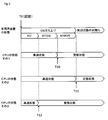
第2実施形態では、車両用装置1は、所定期間として、起動からCPU3上で動作するOSが立ち上がるまでの期間において、CPU3を高速状態に設定する。このとき、車両用装置1には、図2に示したようにハイパーバイザ20、OS30およびOS40が動作する。これらハイパーバイザ20、OS30およびOS40は、図4に示すように、OSの立ち上げ時には、まずハイパーバイザ20が立ち上がり、次にOS30が立ち上がり、最後にOS40が立ち上がる構成となっている。
In the second embodiment, the vehicle device 1 sets the CPU 3 to a high-speed state in a predetermined period from the start to the start of the OS running on the CPU 3. At this time, the hypervisor 20, OS30, and OS40 operate on the vehicle device 1 as shown in FIG. As shown in FIG. 4, the hypervisor 20, OS30, and OS40 have a configuration in which the hypervisor 20 starts up first, then the OS30 starts up, and finally the OS40 starts up when the OS starts up.
この場合、図4にCPU3の状態その1として示すように、車両用装置1つまり設定部3bは、起動した時刻T0からOS30が立ち上がる時刻T10までの期間を所定期間とし、CPU3を高速状態に設定することができる。上記したように、OS30はGNSSモジュール6の処理を担当しており、そのGNSSモジュール6は、OS40のナビアプリ40gによって利用される。そのため、OS30が立ち上がったらCPU3を定格状態としてGNSSモジュール6をノイズの影響を受けない状態とすることで、OS40が立ち上がって直ぐにGNSSモジュール6が利用されても問題が発生しないようにすることができ、誤動作や性能劣化を防止することができる。
In this case, as shown in FIG. 4 as the state 1 of the CPU 3, the vehicle device 1, that is, the setting unit 3b sets the CPU 3 to the high-speed state by setting the period from the start time T0 to the start time T10 of the OS 30 as a predetermined period. can do. As described above, the OS 30 is in charge of processing the GNSS module 6, and the GNSS module 6 is used by the navigation application 40g of the OS 40. Therefore, by setting the CPU 3 in the rated state and the GNSS module 6 in a state not affected by noise when the OS 30 starts up, it is possible to prevent a problem from occurring even if the GNSS module 6 is used immediately after the OS 40 starts up. , It is possible to prevent malfunction and performance deterioration.
また、図4にCPU3の状態その2として示すように、車両用装置1は、起動した時刻T0からOS40が立ち上がる時刻T11までの期間を所定期間とし、CPU3を高速状態に設定することができる。上記したように、OS40はラジオ放送やテレビ放送を提供しており、それらの機能はユーザの操作によって開始されると考えられる。そのため、OS40が立ち上がった時点でCPU3を定格状態にすることで、ラジオモジュールやテレビモジュールをノイズの影響を受けない状態とすることができ、いつユーザが操作しても問題が発生しないようにすることができ、誤動作や性能劣化を防止することができる。
Further, as shown in FIG. 4 as the state 2 of the CPU 3, the vehicle device 1 can set the CPU 3 to the high-speed state by setting the period from the start time T0 to the start time T11 of the OS 40 as a predetermined period. As described above, the OS 40 provides radio broadcasting and television broadcasting, and it is considered that these functions are started by a user operation. Therefore, by setting the CPU 3 to the rated state when the OS 40 starts up, the radio module and the TV module can be in a state where they are not affected by noise, and no problem occurs no matter when the user operates them. It is possible to prevent malfunction and performance deterioration.
あるいは、図4にCPU3の状態その3として示すように、車両用装置1は、起動した時刻T0からハイパーバイザ20が立ち上がる時刻T12までの期間を所定期間とし、CPU3を高速状態に設定することができる。ハイパーバイザ20は、OS30やOS40からのアクセスを仲介するための仮想デバイスを提供する。そのため、ハイパーバイザ20が立ち上がった時点で初期化が完了している周辺回路も存在する。また、ハイパーバイザ20自体が周辺回路にアクセスすることもある。
Alternatively, as shown in FIG. 4 as the state 3 of the CPU 3, the vehicle device 1 may set the CPU 3 to the high-speed state by setting the period from the start time T0 to the start time T12 of the hypervisor 20 as a predetermined period. it can. The hypervisor 20 provides a virtual device for mediating access from OS 30 or OS 40. Therefore, there are peripheral circuits whose initialization is completed when the hypervisor 20 starts up. In addition, the hypervisor 20 itself may access peripheral circuits.
そのため、ハイパーバイザ20が立ち上がった時点でCPU3を定格状態にすることで、ハイパーバイザ20がアクセスする周辺回路をノイズの影響を受けない状態とすることができ、誤動作や性能劣化を防止することができる。なお、ハイパーバイザ20が例えばOS30の機能の一部として実装されている場合には、ハイパーバイザ20のアプリケーションが実行されるまでの期間、または、ハイパーバイザ20を実現する機能部が実行されるまでの期間、CPU3を高速状態とすることもできる。
Therefore, by setting the CPU 3 to the rated state when the hypervisor 20 starts up, the peripheral circuits accessed by the hypervisor 20 can be made unaffected by noise, and malfunction and performance deterioration can be prevented. it can. When the hypervisor 20 is implemented as a part of the function of the OS 30, for example, the period until the application of the hypervisor 20 is executed, or until the functional unit that realizes the hypervisor 20 is executed. The CPU 3 can be put into a high-speed state during the above period.
(第3実施形態)
以下、第3実施形態について、図6から図8を参照しながら説明する。第3実施形態では、第1実施形態および第2実施形態とは異なる所定期間の例について説明する。なお、車両用装置1の構成は第1実施形態と共通するので、図1および図2も参照しながら説明する。 (Third Embodiment)
Hereinafter, the third embodiment will be described with reference to FIGS. 6 to 8. In the third embodiment, an example of a predetermined period different from the first embodiment and the second embodiment will be described. Since the configuration of thevehicle device 1 is the same as that of the first embodiment, it will be described with reference to FIGS. 1 and 2.
以下、第3実施形態について、図6から図8を参照しながら説明する。第3実施形態では、第1実施形態および第2実施形態とは異なる所定期間の例について説明する。なお、車両用装置1の構成は第1実施形態と共通するので、図1および図2も参照しながら説明する。 (Third Embodiment)
Hereinafter, the third embodiment will be described with reference to FIGS. 6 to 8. In the third embodiment, an example of a predetermined period different from the first embodiment and the second embodiment will be described. Since the configuration of the
車両用装置1は、図6に示すように、所定期間として、起動から周辺回路の初期化が完了するまでの期間において、CPU3を高速状態に設定している。これにより、OS30やOS40で利用される周辺回路を迅速に初期化でき、OS30やOABが起動後に各機能を素早く実行することができる。
As shown in FIG. 6, the vehicle device 1 sets the CPU 3 to a high-speed state in a predetermined period from the start to the completion of the initialization of the peripheral circuit. As a result, the peripheral circuits used in OS30 and OS40 can be quickly initialized, and each function can be quickly executed after OS30 and OAB are started.
このとき、車両用装置1は、図7に示すように、特定の周辺回路の初期化が完了するまでの期間において、CPU3を高速状態に設定することができる。この場合、特定の周辺回路としては、例えば高速起動が必要な機能によって利用されるものを対象とすることができる。これにより、高速起動が必要な機能が実行される時点でCPU3が定格状態になるため、高速起動が必要な機能に対してノイズの影響を与えることを防止できる。
At this time, as shown in FIG. 7, the vehicle device 1 can set the CPU 3 to the high-speed state in the period until the initialization of the specific peripheral circuit is completed. In this case, as the specific peripheral circuit, for example, a circuit used by a function that requires high-speed startup can be targeted. As a result, since the CPU 3 is in the rated state when the function requiring high-speed startup is executed, it is possible to prevent the influence of noise on the function requiring high-speed startup.
あるいは、車両用装置1は、図8に示すように、OSの立ち上げ中に例えばOS30側で特定の周辺回路の初期化が完了するまでの期間、CPU3を高速状態に設定することができる。例えば、高速起動が必要な機能であるリアカメラ14の映像は、CPU3をショートカットして表示するような構成とすることができる。その場合、映像入力部5や映像出力部11の初期化が完了すれば、OS30やOS40の立ち上げの完了を待たなくても表示することで、より迅速な表示を行うことができるようになる。
Alternatively, as shown in FIG. 8, the vehicle device 1 can set the CPU 3 to a high-speed state during the startup of the OS, for example, until the initialization of a specific peripheral circuit is completed on the OS 30 side. For example, the image of the rear camera 14, which is a function that requires high-speed startup, can be configured to display the CPU 3 as a shortcut. In that case, if the initialization of the video input unit 5 and the video output unit 11 is completed, the display can be performed more quickly without waiting for the completion of the startup of the OS 30 and OS 40. ..
本開示は、実施例に準拠して記述されたが、本開示は当該実施例や構造に限定されるものではないと理解される。本開示は、様々な変形例や均等範囲内の変形をも包含する。加えて、様々な組み合わせや形態、さらには、それらに一要素のみ、それ以上、あるいはそれ以下、を含む他の組み合わせや形態をも、本開示の範疇や思想範囲に含まれるものである。
Although the present disclosure has been described according to the embodiments, it is understood that the present disclosure is not limited to the embodiments and the structure. The present disclosure also includes various modifications and modifications within an equal range. In addition, various combinations and forms, as well as other combinations and forms that include only one element, more, or less, are also included in the scope and scope of the present disclosure.
各実施形態では定格クロックが1つである例を示したが、定格クロックが複数あり、それらが切り替わるものを採用することもできる。その場合、切り替わる動作クロックが既知であることから、予め各動作クロックに対するノイズ設計をしておけばノイズが影響を与えることを防止できる。
In each embodiment, an example in which the rated clock is one is shown, but it is also possible to adopt a clock having a plurality of rated clocks and switching between them. In that case, since the operating clock to be switched is known, it is possible to prevent the noise from affecting by designing the noise for each operating clock in advance.
本開示に記載の制御部及びその手法は、コンピュータプログラムにより具体化された一つ乃至は複数の機能を実行するようにプログラムされたプロセッサ及びメモリを構成することによって提供された専用コンピュータにより、実現されてもよい。あるいは、本開示に記載の制御部及びその手法は、一つ以上の専用ハードウェア論理回路によってプロセッサを構成することによって提供された専用コンピュータにより、実現されてもよい。もしくは、本開示に記載の制御部及びその手法は、一つ乃至は複数の機能を実行するようにプログラムされたプロセッサ及びメモリと一つ以上のハードウェア論理回路によって構成されたプロセッサとの組み合わせにより構成された一つ以上の専用コンピュータにより、実現されてもよい。また、コンピュータプログラムは、コンピュータにより実行されるインストラクションとして、コンピュータ読み取り可能な非遷移有形記録媒体に記憶されていてもよい。
The control unit and its method described in the present disclosure are realized by a dedicated computer provided by configuring a processor and a memory programmed to execute one or more functions embodied by a computer program. May be done. Alternatively, the control unit and the method described in the present disclosure may be realized by a dedicated computer provided by configuring a processor with one or more dedicated hardware logic circuits. Alternatively, the control unit and method thereof described in the present disclosure may be a combination of a processor and memory programmed to perform one or more functions and a processor composed of one or more hardware logic circuits. It may be realized by one or more dedicated computers configured. Further, the computer program may be stored in a computer-readable non-transitional tangible recording medium as an instruction executed by the computer.
Claims (6)
- 定格の動作クロックで動作する定格状態と、定格の動作クロックよりも高速であって動作可能な高速状態とを設定可能なCPU(3)と、
前記CPU(3)を定格状態または高速状態のいずれかに設定する設定部(3b)と、を備え、
前記設定部(3b)は、起動から所定期間において前記CPU(3)を高速状態に設定するとともに、所定期間が経過した後は前記CPU(3)を定格状態に設定する車両用装置。 A CPU (3) capable of setting a rated state that operates at a rated operating clock and a high-speed state that can operate at a speed higher than the rated operating clock.
A setting unit (3b) for setting the CPU (3) to either a rated state or a high-speed state is provided.
The setting unit (3b) is a vehicle device that sets the CPU (3) to a high-speed state in a predetermined period from the start and sets the CPU (3) to a rated state after the predetermined period elapses. - 前記設定部は、所定期間として、起動からヒューマンマシンインターフェースの提供が開始されるまでの期間において、前記CPUを高速状態に設定する請求項1記載の車両用装置。 The vehicle device according to claim 1, wherein the setting unit sets the CPU to a high-speed state in a predetermined period from the start to the start of providing the human machine interface.
- 前記設定部は、所定期間として、起動から前記CPU上で動作するアプリケーション(30a、30b、30c、40a、40b、40c、40d、40e、40f、40g)が実行されるまでの期間において、前記CPUを高速状態に設定する請求項1記載の車両用装置。 The setting unit sets the CPU in a predetermined period from the start to the execution of the application (30a, 30b, 30c, 40a, 40b, 40c, 40d, 40e, 40f, 40g) operating on the CPU. The vehicle device according to claim 1, wherein the high speed state is set.
- 前記CPUによって制御される機能部(4、5、6、7、8、9、10、11、30a、30b、30c、40a、40b、40c、40d、40e、40f、40g)を備え、
前記設定部は、所定期間として、起動から前記機能部(4、5、6、7、8、9、10、11、30a、30b、30c、40a、40b、40c、40d、40e、40f、40g)の動作が開始されるまでの期間において、前記CPUを高速状態に設定する請求項1記載の車両用装置。 It includes functional units (4, 5, 6, 7, 8, 9, 10, 11, 30a, 30b, 30c, 40a, 40b, 40c, 40d, 40e, 40f, 40g) controlled by the CPU.
The setting unit is set as a predetermined period from the start to the functional unit (4, 5, 6, 7, 8, 9, 10, 11, 30a, 30b, 30c, 40a, 40b, 40c, 40d, 40e, 40f, 40g. The vehicle device according to claim 1, wherein the CPU is set to a high-speed state in the period until the operation of) is started. - 前記設定部は、所定期間として、起動から前記CPU上で動作するオペレーティングシステム(20、30、40)が立ち上がるまでの期間において、前記CPUを高速状態に設定する請求項1記載の車両用装置。 The vehicle device according to claim 1, wherein the setting unit sets the CPU to a high-speed state during a period from startup to startup of the operating system (20, 30, 40) operating on the CPU as a predetermined period.
- 前記CPUに接続されている周辺回路(4、5、6、7、8、9、10、11)を備え、
前記設定部は、所定期間として、起動から前記周辺回路(4、5、6、7、8、9、10、11)の初期化が完了するまでの期間において、前記CPUを高速状態に設定する請求項1記載の車両用装置。
Peripheral circuits (4, 5, 6, 7, 8, 9, 10, 11) connected to the CPU are provided.
The setting unit sets the CPU to a high-speed state in a predetermined period from the start to the completion of initialization of the peripheral circuits (4, 5, 6, 7, 8, 9, 10, 11). The vehicle device according to claim 1.
Priority Applications (3)
| Application Number | Priority Date | Filing Date | Title |
|---|---|---|---|
| DE112020001209.3T DE112020001209T5 (en) | 2019-03-13 | 2020-02-17 | Vehicle device |
| CN202080019970.XA CN113557177A (en) | 2019-03-13 | 2020-02-17 | Vehicle device |
| US17/398,352 US11755059B2 (en) | 2019-03-13 | 2021-08-10 | System for setting an operating clock of a CPU of a vehicular device |
Applications Claiming Priority (2)
| Application Number | Priority Date | Filing Date | Title |
|---|---|---|---|
| JP2019045892A JP2020149317A (en) | 2019-03-13 | 2019-03-13 | Vehicle device |
| JP2019-045892 | 2019-03-13 |
Related Child Applications (1)
| Application Number | Title | Priority Date | Filing Date |
|---|---|---|---|
| US17/398,352 Continuation US11755059B2 (en) | 2019-03-13 | 2021-08-10 | System for setting an operating clock of a CPU of a vehicular device |
Publications (1)
| Publication Number | Publication Date |
|---|---|
| WO2020184074A1 true WO2020184074A1 (en) | 2020-09-17 |
Family
ID=72427797
Family Applications (1)
| Application Number | Title | Priority Date | Filing Date |
|---|---|---|---|
| PCT/JP2020/006058 WO2020184074A1 (en) | 2019-03-13 | 2020-02-17 | Vehicular device |
Country Status (5)
| Country | Link |
|---|---|
| US (1) | US11755059B2 (en) |
| JP (1) | JP2020149317A (en) |
| CN (1) | CN113557177A (en) |
| DE (1) | DE112020001209T5 (en) |
| WO (1) | WO2020184074A1 (en) |
Citations (3)
| Publication number | Priority date | Publication date | Assignee | Title |
|---|---|---|---|---|
| JP2001005661A (en) * | 1999-06-18 | 2001-01-12 | Toshiba Corp | Computer system and method for controlling performance of cpu in the system |
| JP2004266661A (en) * | 2003-03-03 | 2004-09-24 | Ricoh Co Ltd | Image forming apparatus |
| JP2008186175A (en) * | 2007-01-29 | 2008-08-14 | Toyota Motor Corp | Start control method of operating system and information processor |
Family Cites Families (32)
| Publication number | Priority date | Publication date | Assignee | Title |
|---|---|---|---|---|
| JP3426645B2 (en) * | 1993-05-13 | 2003-07-14 | 株式会社東芝 | Data processing system |
| JPH09185582A (en) * | 1995-12-29 | 1997-07-15 | Nec Corp | Clock control system and its method for local bus |
| WO1997027545A1 (en) * | 1996-01-26 | 1997-07-31 | Exabyte Corporation | Dynamic control of magnetic tape drive |
| JPH1165712A (en) * | 1997-08-11 | 1999-03-09 | Nec Gumma Ltd | Information processor |
| JP3575300B2 (en) * | 1998-11-12 | 2004-10-13 | トヨタ自動車株式会社 | Mobile computer |
| JP2001117663A (en) * | 1999-10-21 | 2001-04-27 | Toshiba Corp | Computer system and method for controlling processing speed of the same |
| US6681336B1 (en) * | 1999-06-18 | 2004-01-20 | Kabushiki Kaisha Toshiba | System and method for implementing a user specified processing speed in a computer system and for overriding the user specified processing speed during a startup and shutdown process |
| JP3758477B2 (en) * | 2000-08-02 | 2006-03-22 | 株式会社デンソー | Microcomputer |
| JP2002229791A (en) * | 2001-01-31 | 2002-08-16 | Denso Corp | Interface generating device, program, and storage medium |
| JP2003337634A (en) * | 2002-05-22 | 2003-11-28 | Mitsubishi Electric Corp | Computer apparatus, method for controlling processor, program for running the method by computer, computer- readable recording medium with the program recorded thereon |
| JP4033066B2 (en) * | 2003-05-07 | 2008-01-16 | ソニー株式会社 | Frequency control apparatus, information processing apparatus, frequency control method, and program |
| US20050050310A1 (en) | 2003-07-15 | 2005-03-03 | Bailey Daniel W. | Method, system, and apparatus for improving multi-core processor performance |
| US7380148B2 (en) * | 2004-02-19 | 2008-05-27 | Dell Products L.P. | System and method for information handling system multimedia mode boot optimization |
| US7469372B2 (en) * | 2005-05-13 | 2008-12-23 | Texas Instruments Incorporated | Scan sequenced power-on initialization |
| CN100485633C (en) * | 2006-03-23 | 2009-05-06 | 鸿富锦精密工业(深圳)有限公司 | CPU frequency regulation circuit |
| JP2008198072A (en) * | 2007-02-15 | 2008-08-28 | Mitsubishi Electric Corp | Real-time computer |
| JP2009040280A (en) * | 2007-08-09 | 2009-02-26 | Auto Network Gijutsu Kenkyusho:Kk | In-vehicle control device |
| JP5308043B2 (en) * | 2008-03-21 | 2013-10-09 | 東芝テック株式会社 | Information processing apparatus, clock control method thereof, and clock control program |
| JP5407211B2 (en) * | 2008-07-31 | 2014-02-05 | 株式会社オートネットワーク技術研究所 | Processing apparatus, clock frequency determination method, and computer program |
| JP2010079566A (en) * | 2008-09-25 | 2010-04-08 | Alpine Electronics Inc | Information processing apparatus and method of starting application |
| TW201044136A (en) * | 2009-06-12 | 2010-12-16 | Micro Star Int Co Ltd | External frequency adjustment methods and systems, and computer program products thereof |
| JP2011096145A (en) * | 2009-10-30 | 2011-05-12 | Pioneer Electronic Corp | Information processor, method of controlling startup, startup control program, and recording medium |
| US20130114203A1 (en) * | 2011-11-07 | 2013-05-09 | Sergey Ignatchenko | Systems, Apparatuses and Methods for Improving the Performance of Computing Devices |
| US9098277B2 (en) * | 2012-08-30 | 2015-08-04 | Dell Products L.P. | Information handling system configuration for power system output capability |
| JP5595571B1 (en) * | 2013-09-13 | 2014-09-24 | 三菱電機株式会社 | Control device |
| JP6523298B2 (en) * | 2014-01-06 | 2019-05-29 | ジョンソン コントロールズ テクノロジー カンパニーJohnson Controls Technology Company | Computer system and vehicle interface system |
| US10776130B2 (en) * | 2014-07-10 | 2020-09-15 | Harman International Industries, Incorporated | Operating system startup acceleration |
| JP2016179801A (en) * | 2015-03-25 | 2016-10-13 | 株式会社デンソー | On-board system |
| CN107256150A (en) * | 2017-05-27 | 2017-10-17 | 深圳酷旗互联网有限公司 | It is a kind of to shorten the method to set up without screen Android device starting up's time |
| JP7043755B2 (en) | 2017-08-29 | 2022-03-30 | ソニーグループ株式会社 | Information processing equipment, information processing methods, programs, and mobiles |
| JP7278753B2 (en) * | 2018-11-19 | 2023-05-22 | キヤノン株式会社 | Information processing equipment capable of detecting falsification of software |
| US11766975B2 (en) * | 2019-07-17 | 2023-09-26 | Marvell Asia Pte, Ltd. | Managing power in an integrated circuit for high-speed activation |
-
2019
- 2019-03-13 JP JP2019045892A patent/JP2020149317A/en active Pending
-
2020
- 2020-02-17 CN CN202080019970.XA patent/CN113557177A/en active Pending
- 2020-02-17 WO PCT/JP2020/006058 patent/WO2020184074A1/en active Application Filing
- 2020-02-17 DE DE112020001209.3T patent/DE112020001209T5/en active Pending
-
2021
- 2021-08-10 US US17/398,352 patent/US11755059B2/en active Active
Patent Citations (3)
| Publication number | Priority date | Publication date | Assignee | Title |
|---|---|---|---|---|
| JP2001005661A (en) * | 1999-06-18 | 2001-01-12 | Toshiba Corp | Computer system and method for controlling performance of cpu in the system |
| JP2004266661A (en) * | 2003-03-03 | 2004-09-24 | Ricoh Co Ltd | Image forming apparatus |
| JP2008186175A (en) * | 2007-01-29 | 2008-08-14 | Toyota Motor Corp | Start control method of operating system and information processor |
Also Published As
| Publication number | Publication date |
|---|---|
| CN113557177A (en) | 2021-10-26 |
| US20210373590A1 (en) | 2021-12-02 |
| US11755059B2 (en) | 2023-09-12 |
| DE112020001209T5 (en) | 2021-12-23 |
| JP2020149317A (en) | 2020-09-17 |
Similar Documents
| Publication | Publication Date | Title |
|---|---|---|
| CN104853142B (en) | Controller for vehicle-mounted Ethernet and control method thereof | |
| CN106537335B (en) | Operating system boot acceleration | |
| WO2017202195A1 (en) | Vehicle control method, vehicle main board, control system, and vehicle | |
| KR101979138B1 (en) | Vehicle Mounting System | |
| US20200290530A1 (en) | Vehicle software control device | |
| CN106663009B (en) | Operating system boot acceleration | |
| JP3575300B2 (en) | Mobile computer | |
| JP2021005217A (en) | Vehicle control system and electronic control device | |
| US20220073019A1 (en) | Vehicle device | |
| US20170168848A1 (en) | Operating system startup acceleration | |
| WO2020184074A1 (en) | Vehicular device | |
| US20240036856A1 (en) | Vehicle system | |
| CN114816800B (en) | Event processing method and device applied to internet of things (IoT) device | |
| US11750923B2 (en) | Vehicle control system, vehicle control method, controller, and non-transitory storage medium | |
| US11408388B2 (en) | Vehicular control apparatus | |
| CN116135610A (en) | Systems and methods for an expandable cockpit controller | |
| WO2024143007A1 (en) | Vehicle-mounted apparatus, vehicle-mounted system, method, and program | |
| CN111356994B (en) | Modular computer architecture for a cockpit and infotainment system of a vehicle | |
| US20240037999A1 (en) | Vehicle system | |
| US12097814B2 (en) | Vehicular device | |
| CN112638720B (en) | Vehicle control system | |
| JP2022114164A (en) | Device for vehicle, system for vehicle, and external device | |
| JP2008059448A (en) | Bus system and bus system control method | |
| CN114056262A (en) | Vehicle-mounted display logic method and device, intelligent automobile and readable storage medium | |
| CN118528944A (en) | Vehicle-mounted control device |
Legal Events
| Date | Code | Title | Description |
|---|---|---|---|
| 121 | Ep: the epo has been informed by wipo that ep was designated in this application |
Ref document number: 20769497 Country of ref document: EP Kind code of ref document: A1 |
|
| 122 | Ep: pct application non-entry in european phase |
Ref document number: 20769497 Country of ref document: EP Kind code of ref document: A1 |