WO2020184008A1 - 通信システムおよび通信システムの通信方法 - Google Patents
通信システムおよび通信システムの通信方法 Download PDFInfo
- Publication number
- WO2020184008A1 WO2020184008A1 PCT/JP2020/004545 JP2020004545W WO2020184008A1 WO 2020184008 A1 WO2020184008 A1 WO 2020184008A1 JP 2020004545 W JP2020004545 W JP 2020004545W WO 2020184008 A1 WO2020184008 A1 WO 2020184008A1
- Authority
- WO
- WIPO (PCT)
- Prior art keywords
- reader
- communication
- writer
- standby
- time
- Prior art date
- Legal status (The legal status is an assumption and is not a legal conclusion. Google has not performed a legal analysis and makes no representation as to the accuracy of the status listed.)
- Ceased
Links
Images

Classifications
-
- G—PHYSICS
- G06—COMPUTING OR CALCULATING; COUNTING
- G06K—GRAPHICAL DATA READING; PRESENTATION OF DATA; RECORD CARRIERS; HANDLING RECORD CARRIERS
- G06K7/00—Methods or arrangements for sensing record carriers, e.g. for reading patterns
- G06K7/10—Methods or arrangements for sensing record carriers, e.g. for reading patterns by electromagnetic radiation, e.g. optical sensing; by corpuscular radiation
- G06K7/10009—Methods or arrangements for sensing record carriers, e.g. for reading patterns by electromagnetic radiation, e.g. optical sensing; by corpuscular radiation sensing by radiation using wavelengths larger than 0.1 mm, e.g. radio-waves or microwaves
- G06K7/10297—Methods or arrangements for sensing record carriers, e.g. for reading patterns by electromagnetic radiation, e.g. optical sensing; by corpuscular radiation sensing by radiation using wavelengths larger than 0.1 mm, e.g. radio-waves or microwaves arrangements for handling protocols designed for non-contact record carriers such as RFIDs NFCs, e.g. ISO/IEC 14443 and 18092
-
- H—ELECTRICITY
- H04—ELECTRIC COMMUNICATION TECHNIQUE
- H04B—TRANSMISSION
- H04B5/00—Near-field transmission systems, e.g. inductive or capacitive transmission systems
- H04B5/70—Near-field transmission systems, e.g. inductive or capacitive transmission systems specially adapted for specific purposes
- H04B5/77—Near-field transmission systems, e.g. inductive or capacitive transmission systems specially adapted for specific purposes for interrogation
Definitions
- the present invention relates to a communication system that prevents interference between readers and writers that transmit and receive information with a wireless tag.
- Patent Document 1 discloses a technique in which a management server controls the start / end of carrier sense and the transmission / stop of radio signals by a questioner (corresponding to a reader / writer).
- the worker gives priority to each interrogator, and when granting the right to perform wireless communication, the management server grants the right to perform wireless communication to the interrogator with high priority first. The method is disclosed.
- Japanese Patent Publication Japanese Patent Application Laid-Open No. 2007-317174
- One aspect of the present invention is to provide a communication system capable of setting a priority for a reader / writer and performing communication with a wireless tag without inviting complication of the system.
- the communication system is a communication system including a plurality of reader / writers that read and write data to a plurality of RFID tags.
- the above-mentioned Performs at least one of a process of waiting for the start of communication with the RFID tag to be communicated with a predetermined waiting time and a process of waiting with a predetermined waiting time after the communication process with the RFID tag to be communicated is completed.
- a standby unit is provided, and among the plurality of reader / writers, the average value of the standby time of the first reader / writer is set shorter than the average value of the standby time of the second reader / writer.
- the communication method of the communication system is a communication method in a communication system including a plurality of readers / writers that read and write data to a plurality of RFID tags.
- each reader / writer detects a radio wave emitted when another reader / writer communicates with the RFID tag, and detects the radio wave of the other reader / writer before communicating with the RFID tag to be communicated
- the communication is performed. Waiting to perform at least one of a process of waiting for the start of communication with the target RFID tag in a predetermined waiting time and a process of waiting in a predetermined waiting time after the communication process with the communication target RFID tag is completed.
- the average value of the standby time of the first reader / writer is set shorter than the average value of the standby time of the second reader / writer.
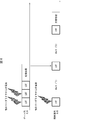
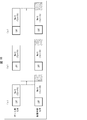
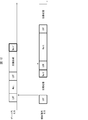
- the gate R / W2 and the shelf management R / W3 receive the communication instruction at the same timing, and the radio wave from another reader / writer is detected at that time.
- the standby time is set by a fixed method in which the standby time of the gate R / W2 is 0, the gate R / W2 and the shelf management R / W3 receive the communication instruction at the same timing, and at that time, the other
- the other It is a timing chart which shows the example of the communication sequence when the radio wave from the reader / writer of is detected. It is a timing chart which shows the example of the communication sequence in the case where the standby time is set by the fixed method which set the standby time of R / W2 for a gate to 0, and the radio wave is not emitted from another reader / writer.
- FIG. 1 is a block diagram showing a configuration of a communication system 100 according to the present embodiment.
- the communication system 100 has a gate R / W (first reader / writer) 2 that reads and writes data to a plurality of RFID tags 4 and a shelf management R / W. It is equipped with W (second reader / writer) 3.
- the gate R / W2 has a detection unit 27 that detects radio waves emitted when another reader / writer communicates with the RFID tag 4, and detects radio waves of the other reader / writer before communicating with the RFID tag 4 to be communicated with. Then, a standby unit 26 that waits for the start of communication with the RFID tag 4 for a predetermined standby time is provided.
- the shelf management R / W3 has a detection unit 37 that detects radio waves emitted when another reader / writer communicates with the RFID tag 4, and another reader / writer before communicating with the RFID tag 4 to be communicated with.
- the RFID tag 4 is provided with a standby unit 36 that waits for the start of communication with the RFID tag 4 within a predetermined standby time.
- the average value of the waiting time of the gate R / W2 is set shorter than the average value of the waiting time of the shelf management R / W3. As a result, it is possible to perform communication in a state where the priority of the gate R / W2 is higher than that of the shelf management R / W3.
- the communication system 100 may be provided with three or more reader / writers for which priority should be set, and the length of each standby time may be set to be shorter as the priority is higher.
- the communication system 100 includes a gate R / W2, a shelf management R / W3, a PLC (Programmable Logic Controller) 1, which is a higher-level system that collectively manages a plurality of reader / writers, and a reader / writer. And an RFID (Radio Frequency Identifier) tag 4 on a carrier 5 and a shelf 6 for transmitting and receiving data.
- the PLC1 and the gate R / W2 and the shelf management R / W3 are communicated and connected via a communication network.
- the communication system 100 may include a reader / writer in addition to the gate R / W2 and the shelf management R / W3.
- the gate R / W2 communicates with the RFID tag 4 attached to the product loaded on the transport vehicle 5. That is, the gate R / W2 has its own arrangement position fixed and communicates with the RFID tag 4 passing through the communication area. This makes it possible to recognize the products loaded on the transport vehicle 5 that has passed through the gate.
- the gate R / W2 includes an upper communication unit 21, an RF (Radio Frequency) communication unit 22, and an antenna 23.
- the upper communication unit 21 controls communication with the PLC 1, transmits an instruction from the PLC 1 to the RF communication unit 22, and transmits an output from the RF communication unit 22 to the PLC 1.
- the RF communication unit 22 controls communication of radio waves transmitted and received by the antenna 23.
- the RFID tag 4 since it is assumed that the RFID tag 4 as the communication target of the gate R / W2 is moving, real-time performance is required for wireless communication with the gate R / W2.
- the standby unit 26 included in the RF communication unit 22 holds standby time information indicating the standby time.
- This waiting time information can be changed by an instruction from the outside.
- the standby time information may be rewritten according to an instruction from the PLC 1, or the standby time information may be rewritten by a PC or the like directly connected to the gate R / W2 by USB (Universal Serial Bus) or the like.
- the gate R / W2 may include an input unit that receives input from the user, and the standby time information may be rewritten by this input unit (button, switch, touch panel, etc.).
- the shelf management R / W 3 communicates with the RFID tag 4 attached to the product mounted on the shelf 6. That is, the shelf management R / W3 communicates with the RFID tag 4 that has not moved by moving itself by being transported by the user. This makes it possible to recognize what kind of product is placed on the shelf 6.
- the shelf management R / W3 includes an upper communication unit 31, an RF communication unit 32, an antenna 33, and a trigger switch 34.
- the upper communication unit 31, the RF communication unit 32, and the antenna 33 have the same functions as the upper communication unit 21, the RF communication unit 22, and the antenna 23 described above.
- the trigger switch 34 accepts an operation by the user, and transmits an instruction to start communication with the ID tag 4 to the RF communication unit 32 at the timing operated by the user.
- the instruction to start the communication with the ID tag 4 may be received from the PLC1.
- the wireless communication with the shelf management R / W3 is compared with the gate R / W2. Real-time performance is not required.
- the transport vehicle 5 and the RFID tag 4 on the shelf 6 are shown by two each, but the present invention is not limited to this, and one or more RFID tags 4 may be used.
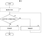
- FIG. 2 is a flowchart showing a flow of communication processing with the RFID tag 4 in the gate R / W2 and the shelf management R / W3. Since the basic communication processing flow is the same for the gate R / W2 and the shelf management R / W3, the gate R / W2 will be described here as an example.
- step 1 when the host communication unit 21 receives a signal indicating a reading instruction from the PLC 1, it transmits to that effect to the RF communication unit 22.
- the trigger switch 34 may transmit the operation input by the user as a reading instruction to the RF communication unit 22.
- the detection unit 27 in the RF communication unit 22 confirms whether or not the radio wave from another reader / writer is detected by the antenna 23 by the LBT (Listen Before Talk) function. YES in S2, that is, when the detection unit 27 detects a radio wave from another reader / writer, the standby unit 26 in the RF communication unit 22 performs a process of waiting for RF communication in a predetermined standby time (S3). When the standby process is completed, the process returns from S2.
- the RF communication unit 22 starts RF communication and performs communication processing with the RFID tag 4 (S4).
- the waiting time setting method for the gate R / W2 and the shelf management R / W3 can be roughly divided into a fixed method and a random method.
- the fixed method is a method in which the standby time is set as a fixed value in each reader / writer.
- the standby time of the leader / writer with high priority, that is, the gate R / W2 is set to T1 (fixed value)
- the standby time of the reader / writer with low priority that is, the shelf management R / W3 is set to T2 (fixed value). Value)
- the random method is a method in which each reader / writer sets the waiting time as a random value consisting of a predetermined range each time a standby process occurs.
- the standby time of the leader / writer with high priority, that is, the gate R / W2 is set to a random value in the range of T3 to T4, and the standby time of the reader / writer with low priority, that is, the shelf management R / W3.
- the average of the random values in the range of T3 to T4 is set to be shorter than the average of the random values in the range of T5 to T6.
- the above T3 may be 0.
- either one of the gate R / W2 and the shelf management R / W3 may be a fixed method and the other may be a random method.
- LBT is performed at the time of receiving the communication instruction in the gate R / W2 and the shelf management R / W3. Since radio waves from other reader / writers are detected in this LBT, standby processing is performed. In the gate R / W2, the standby process is performed during the period of T1, and then the LBT is performed again. At this point, radio waves from other reader / writers are not detected, so communication processing is performed after the end of LBT.
- the shelf management R / W3 LBT is performed when the communication instruction is received. Since radio waves from other reader / writers are detected in this LBT, standby processing is performed. In the shelf management R / W3, the standby process is performed in the period of T2, which is longer than that of T1, and then the LBT is performed again. At this point, since the communication process is being performed on the gate R / W2, the radio wave from the gate R / W2 is detected in the LBT. Therefore, the standby process is subsequently performed during the period of T2. After that, LBT is performed again, and at this point, radio waves from other reader / writers are not detected, so communication processing is performed after the end of LBT.
- the standby time of the gate R / W2 is set shorter than the standby time of the shelf management R / W3, the communication processing of the gate R / W2 is preferentially executed. I understand.
- FIG. 4 is a timing chart showing an example of a communication sequence when radio waves are not emitted from other reader / writers when the standby time is set by a fixed method.
- the gate R / W2 first started LBT. Since radio waves from other reader / writers are not detected in this LBT, the gate R / W2 starts the communication process.
- the shelf management R / W3 starts the LBT a little later than the gate R / W2, and detects the radio wave from the gate R / W2 in the middle of the LBT. Therefore, in the shelf management R / W3, the standby process is performed in the period of T2.
- the gate R / W2 After that, in the gate R / W2, after the first communication processing is completed, LBT is performed to perform the second communication processing. Since radio waves from other reader / writers are not detected in this LBT, the gate R / W2 starts the second communication process.
- the shelf management R / W3 performs LBT again after the standby processing is completed, and detects radio waves from the gate R / W2 again in the middle of the LBT. Therefore, in the shelf management R / W3, the standby process is performed again in the period of T2. After that, LBT is performed again, and at this point, radio waves from other reader / writers are not detected, so communication processing is performed after the end of LBT.
- FIG. 5 is a timing chart showing an example of another communication sequence in the case where the standby time is set by the fixed method and the radio wave is not emitted from another reader / writer.
- the shelf management R / W3 first started LBT. Since radio waves from other reader / writers are not detected in this LBT, the shelf management R / W3 starts the communication process.
- the gate R / W2 starts the LBT a little later than the shelf management R / W3, and detects the radio wave from the shelf management R / W3 in the middle of the LBT. Therefore, in the gate R / W2, the standby process is performed during the period of T1.
- the LBT is performed again after the standby processing, and at this point, radio waves from other reader / writers are not detected, so that the communication processing is performed after the end of the LBT.
- the shelf management R / W3 after the first communication process is completed, LBT is performed to perform the second communication process. In the middle of this LBT, the shelf management R / W3 detects radio waves from the gate R / W2. Therefore, in the shelf management R / W3, the standby process is performed in the period of T2. After that, LBT is performed again, and at this point, radio waves from other reader / writers are not detected, so communication processing is performed after the end of LBT.
- the gate R / W2 subsequently acquires the communication right. Communication processing is performed. This is because the standby time of the gate R / W2 is set shorter than the standby time of the shelf management R / W3, so that the probability of acquiring the communication right is increased. That is, even in the example shown in FIG. 5, it can be seen that the communication processing of the gate R / W2 is preferentially executed.
- the standby time of the gate R / W2 is set to 0.
- LBT is performed at the time of receiving the communication instruction. Since radio waves from other reader / writers are detected in this LBT, the LBT is continuously performed because the standby time is 0. At the time of the third LBT, radio waves from other reader / writers are no longer detected, so communication processing is performed after the end of the LBT.
- LBT is performed when the communication instruction is received. Since radio waves from other reader / writers are detected in this LBT, standby processing is performed. In the shelf management R / W3, the standby process is performed during the period of T2, and then the LBT is performed again. At this point, since the communication process is being performed on the gate R / W2, the radio wave from the gate R / W2 is detected in the LBT. Therefore, the standby process is subsequently performed during the period of T2. After that, LBT is performed again, and at this point, radio waves from other reader / writers are not detected, so communication processing is performed after the end of LBT.
- FIG. 7 is a timing chart showing an example of a communication sequence in the case where the standby time is set by a fixed method in which the standby time of the gate R / W2 is 0 and no radio wave is emitted from another reader / writer. ..
- the shelf management R / W3 first started LBT. Since radio waves from other reader / writers are not detected in this LBT, the shelf management R / W3 starts the communication process.
- the gate R / W2 starts the LBT a little later than the shelf management R / W3, and detects the radio wave from the shelf management R / W3 in the middle of the LBT. Therefore, in the gate R / W2, the LBT is continuously performed because the standby time is 0 during the period during which the communication processing by the shelf management R / W3 is performed.
- the shelf management R / W3 after the first communication process is completed, LBT is performed to perform the second communication process. In the middle of this LBT, the shelf management R / W3 detects radio waves from the gate R / W2. Therefore, in the shelf management R / W3, the standby process is performed in the period of T2. After that, LBT is performed again, and at this point, radio waves from other reader / writers are not detected, so communication processing is performed after the end of LBT.
- FIG. 8 is a timing chart showing still another communication sequence example when radio waves are not emitted from other reader / writers when the standby time is set by the fixed method.
- the communication cycle TA of the gate R / W2 matches the standby time of the shelf management R / W3.
- the shelf management R / W3 cannot obtain the communication right forever. That is, as shown in FIG. 6, when the shelf management R / W3 performs LBT during the communication processing period of the gate R / W2, the standby processing is T2 by detecting the radio wave from the gate R / W2. It is done in a period.
- the standby time T2 coincides with the communication cycle TA, the LBT after the standby processing in the shelf management R / W3 overlaps with the timing of the next communication processing of the gate R / W2 every time. .. It should be noted that this phenomenon may occur when there is a leader / writer having a constant communication cycle regardless of the priority level, and the standby time in the other leader / writers matches the update cycle.
- FIG. 9 is a timing chart showing an example of a communication sequence when radio waves are not emitted from another reader / writer when the standby time is set by a random method.
- the standby processing is performed by detecting the radio wave from the gate R / W2.
- the time between T5 and T6 is randomly set as the time for this standby processing.
- the gate R / W2 performs the second communication process after the communication cycle TA.
- the shelf management R / W3 performs LBT after the standby process, and the standby process is performed again by detecting the radio wave of the gate R / W2.
- the time between T5 and T6 is randomly set as the time for this standby processing.
- the shelf management R / W3 performs LBT.
- the gate R / W2 does not perform communication processing, so the shelf management R / W3 performs communication processing after LBT.
- the gate R / W2 performs LBT after the next communication cycle TA, and the standby process is performed by detecting the radio wave of the shelf management R / W3.
- the time between T3 and T4 is randomly set as the time for this standby processing.
- the standby time of the shelf management R / W3 does not continue to match the communication cycle of the gate R / W2, so that the shelf management R / W3 is used.
- communication rights will be given. That is, according to the random method, when there is a reader / writer with a constant communication cycle, it is possible to eliminate the risk that the communication right is not given to a specific reader / writer.
- the range setting of the random value of the waiting time of the gate R / W2 and the shelf management R / W3 will be described.
- the waiting time of the gate R / W2 is set to a random value in the range of T3 to T4
- the waiting time of the shelf management R / W3 is set to a random value in the range of T5 to T6. ..
- T4 which is the upper limit of the random value range of the waiting time of the gate R / W2
- T5 which is the lower limit of the random value range of the waiting time of the shelf management R / W3
- the standby time of the gate R / W2 is always shorter than the standby time of the shelf management R / W3, so that the priority of the gate R / W2 can be surely increased.
- the waiting time of the gate R / W2 and the waiting time of the shelf management R / W3 may be equal depending on the situation. That is, when the waiting times are the same for both, the priority is the same for the gate R / W2 and the shelf management R / W3.
- the waiting time of the gate R / W2 may be longer than the waiting time of the shelf management R / W3 depending on the situation.
- the priority of the gate R / W2 is lower than the priority of the shelf management R / W3. May become.
- the average of the random values in the range of T3 to T4 is set to be shorter than the average of the random values in the range of T5 to T6, any of the random methods 1 to 3. Even so, on average, the gate R / W2 has a higher priority than the shelf management R / W3.
- FIG. 10 is a diagram showing an example of waiting time setting by variation of the waiting time setting method by the random method.
- A of the figure shows an example in which the waiting time of the gate R / W2 is shorter than the waiting time of the shelf management R / W3 in the case of the random method 1.
- B of the figure shows an example in which the standby time of the gate R / W2 and the standby time of the shelf management R / W3 are equal in the case of the random method 2.
- FIG. 3C of the figure shows an example in which the standby time of the gate R / W2 is longer than the standby time of the shelf management R / W3 in the case of the random method 3.
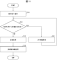
- FIG. 11 is a flowchart showing the flow of communication processing with the RFID tag 4 in the gate R / W2 and the shelf management R / W3 when the standby processing is performed after communication. Since the basic communication processing flow is the same for the gate R / W2 and the shelf management R / W3, the gate R / W2 will be described here as an example.
- the standby unit 26 in the RF communication unit 22 performs the post-communication standby process.
- the standby processing after the communication processing may be started at the end of the communication period secured in the communication processing, or may be at the time when the necessary communication processing is completed before the end of the communication period. Good.
- FIG. 12 is a timing chart showing an example of a communication sequence when radio waves are not emitted from another reader / writer in the case of performing standby processing after communication.
- the shelf management R / W3 first started LBT. Since radio waves from other reader / writers are not detected in this LBT, the shelf management R / W3 starts the communication process. Further, the shelf management R / W3 performs a standby process after the communication process is completed. On the other hand, the gate R / W2 starts the LBT a little later than the shelf management R / W3, and detects the radio wave from the shelf management R / W3 in the middle of the LBT. Therefore, in the gate R / W2, the standby process is performed.
- the LBT is performed again after the standby processing, and at this point, radio waves from other reader / writers are not detected, so that the communication processing is performed after the end of the LBT.
- the shelf management R / W3 after the first communication process is completed and the standby process is completed, LBT is performed to perform the second communication process. In the middle of this LBT, the shelf management R / W3 detects radio waves from the gate R / W2. Therefore, in the shelf management R / W3, the standby process is performed. After that, LBT is performed again, and at this point, radio waves from other reader / writers are not detected, so communication processing is performed after the end of LBT.
- the waiting time of the standby processing after the communication processing may be set to be shorter as the priority of the reader / writer is higher.
- the average value of the waiting time of the standby processing after the communication processing in the gate R / W2 is set shorter than the average value of the waiting time of the waiting processing after the communication processing in the shelf management R / W3. May be good. In this case, the possibility that the gate R / W2 acquires the communication right can be further increased.
- the waiting time of the waiting processing after the communication processing may be set as a fixed value or a random value.
- the standby processing time after LBT may be set equally for each reader / writer, while the standby processing time after communication processing may be set to be shorter as the priority of the reader / writer is higher. This also increases the possibility that the reader / writer with high priority acquires the communication right.
- control blocks of the gate R / W2 and the shelf management R / W3 are formed in an integrated circuit (IC chip) or the like. It may be realized by a logic circuit (hardware) or by software.
- the gate R / W2 and the shelf management R / W3 are equipped with a computer that executes program instructions that are software that realizes each function.
- the computer includes, for example, one or more processors and a computer-readable recording medium that stores the program. Then, in the computer, the object of the present invention is achieved by the processor reading the program from the recording medium and executing the program.
- the processor for example, a CPU (Central Processing Unit) can be used.
- the recording medium in addition to a “non-temporary tangible medium” such as a ROM (Read Only Memory), a tape, a disk, a card, a semiconductor memory, a programmable logic circuit, or the like can be used.
- a RAM Random Access Memory
- the program may be supplied to the computer via an arbitrary transmission medium (communication network, broadcast wave, etc.) capable of transmitting the program.
- a transmission medium communication network, broadcast wave, etc.
- one aspect of the present invention can also be realized in the form of a data signal embedded in a carrier wave, in which the program is embodied by electronic transmission.
- the communication system is a communication system including a plurality of reader / writers that read and write data to a plurality of RFID tags, and each reader / writer. Is a detector that detects a radio wave emitted when another reader / writer communicates with the RFID tag, and detects the radio wave of the other reader / writer before communicating with the RFID tag to be communicated, and then detects the RFID of the communication target.
- a standby unit that performs at least one of a process of waiting for the start of communication with the tag for a predetermined standby time and a process of waiting for a predetermined standby time after the communication process with the RFID tag to be communicated is completed.
- the average value of the standby time of the first reader / writer is set shorter than the average value of the standby time of the second reader / writer.
- the communication method of the communication system is a communication method in a communication system including a plurality of readers / writers that read and write data to a plurality of RFID tags.
- each reader / writer detects a radio wave emitted when another reader / writer communicates with the RFID tag, and detects the radio wave of the other reader / writer before communicating with the RFID tag to be communicated
- the communication is performed. Waiting to perform at least one of a process of waiting for the start of communication with the target RFID tag in a predetermined waiting time and a process of waiting in a predetermined waiting time after the communication process with the communication target RFID tag is completed.
- the average value of the standby time of the first reader / writer is set shorter than the average value of the standby time of the second reader / writer.
- the average value of the standby time of the first reader / writer is set shorter than the average value of the standby time of the second reader / writer, so that the first reader / writer acquires the communication right.
- the possibility can be increased. Therefore, the priority of communication can be set higher for the first reader / writer than for the second reader / writer.
- the priority can be set by setting the standby time in each reader / writer, control by the host system is unnecessary and the system can be set without complication.
- the communication system may have a configuration in which the standby unit of the first reader / writer has a standby time of 0.
- the first reader / writer has the highest priority, and the communication process can be started quickly without waiting time.
- the communication system may have a configuration in which the standby unit of the first reader / writer randomly determines a standby time from a range of T3 or more and T4 or less each time it waits. ..
- the communication cycle becomes equal to the standby time, so that the first reader / writer completely loses the opportunity to acquire the communication right. It is possible to prevent such a situation.
- the communication system may have a configuration in which the standby unit of the second reader / writer randomly determines a standby time from a range of T5 or more and T6 or less each time it waits. ..
- the communication cycle becomes equal to the standby time, so that the second reader / writer completely loses the opportunity to acquire the communication right. It is possible to prevent such a situation.
- the standby unit of the second reader / writer randomly determines the standby time from the range of T5 or more and T6 or less each time the standby unit waits. It may be configured to have a value smaller than T5.
- the standby time of the first reader / writer is always shorter than the standby time of the second reader / writer, so that the priority of the first reader / writer can be surely increased.
- the standby unit of the second reader / writer randomly determines the standby time from the range of T5 or more and T6 or less each time the standby unit waits.
- the configuration may be such that the value is equal to T5.
- the standby time of the first reader / writer and the standby time of the second reader / writer may be equal depending on the situation.
- the first reader / writer and the second reader / writer have priority.
- the degrees can be equal.
- the standby unit of the second reader / writer randomly determines the standby time from the range of T5 or more and T6 or less each time the standby unit waits.
- the value may be larger than T5.
- the standby time of the first reader / writer may be longer than the standby time of the second reader / writer.
- the priority of the first reader / writer is the second reader. It may be lower than the writer's priority. That is, the priority of the first reader / writer can be set weakly.
- the first reader / writer has its own arrangement position fixed and communicates with an RFID tag passing through a communication area.
- the second reader / writer may be configured to communicate with an RFID tag that has not moved by moving itself.
- the first reader / writer needs to communicate with the moving RFID tag within a limited time.
- the second reader / writer only needs to communicate with the RFID tag that is not moving, and there is no time limit. Therefore, in such a system, it is possible to appropriately set a high priority for the first reader / writer, and it is possible to realize the granting of the communication right in a preferable state.
Landscapes
- Engineering & Computer Science (AREA)
- Toxicology (AREA)
- Physics & Mathematics (AREA)
- Health & Medical Sciences (AREA)
- Electromagnetism (AREA)
- Computer Security & Cryptography (AREA)
- Computer Networks & Wireless Communication (AREA)
- General Health & Medical Sciences (AREA)
- Artificial Intelligence (AREA)
- Computer Vision & Pattern Recognition (AREA)
- General Physics & Mathematics (AREA)
- Theoretical Computer Science (AREA)
- Near-Field Transmission Systems (AREA)
Abstract
システムの複雑化を招くことなく、リーダライタに対して優先度を設定して無線タグとの通信を行うことを可能とする通信システムを提供する。各リーダライタは、RFIDタグ(4)と通信する前に、他のリーダライタの電波を検出すると、通信開始を所定の待機時間で待機する処理を行う。ゲート用R/W(2)の待機時間の平均値は、棚管理用R/W(3)の待機時間の平均値よりも短く設定されている。
Description
本発明は、無線タグとの情報の送受信を行うリーダライタ同士の干渉を防ぐ通信システムに関する。
従来、物品などを識別する目的で、無線タグの利用が普及している。無線タグとの情報の送受信を行うリーダライタに関して、複数のリーダライタが同時にアクティブになることによる干渉を防止する手段の例として、LBT(Listen Before Talk)機能がある。しかしながら、LBT機能のみでは、通信を行う権利が平等にリーダライタに対して付与されるので、特定のリーダライタの優先度を高めたいというニーズに対応できない。
これに対して、特許文献1には、管理サーバが質問器(リーダライタに相当)によるキャリアセンスの開始・終了および無線信号の発信・停止を制御する技術が開示されている。また、作業者が各質問器に優先度を与えておき、管理サーバは無線通信を行う権利を付与する際には高い優先度を持つ質問器に対して先に無線通信を行う権利を付与する手法が開示されている。
しかしながら、上述のような従来技術では、上位システムである管理サーバによってリーダライタの優先度のコントロールを行うことになるので、システムとして複雑となり、コストアップや管理の煩雑さを招くという問題がある。また、管理サーバによってリーダライタの通信権の調停が行われるため、調停に伴う処理および通信による待ち時間が発生することになる。よって、例えば、無線タグをゲートに通過させるといったリアルタイム性が必要な場面において十分な対応ができない場合がある、という問題がある。
本発明の一態様は、システムの複雑化を招くことなく、リーダライタに対して優先度を設定して無線タグとの通信を行うことを可能とする通信システムを提供することを目的とする。
上記の課題を解決するために、本発明の一態様に係る通信システムは、複数のRFIDタグに対してデータの読み出しおよび書き込みの少なくともいずれか一方を行う複数のリーダライタを備える通信システムであって、各リーダライタは、他のリーダライタがRFIDタグと通信するときに発する電波を検出する検出部と、通信対象のRFIDタグと通信する前に、他のリーダライタの前記電波を検出すると、前記通信対象のRFIDタグとの通信開始を所定の待機時間で待機する処理、および、前記通信対象のRFIDタグとの交信処理が完了した後に所定の待機時間で待機する処理の少なくともいずれか一方を行う待機部とを備え、前記複数のリーダライタのうち、第1リーダライタの待機時間の平均値は、第2リーダライタの待機時間の平均値よりも短く設定されている構成である。
また、本発明の一態様に係る通信システムの通信方法は、複数のRFIDタグに対してデータの読み出しおよび書き込みの少なくともいずれか一方を行う複数のリーダライタを備える通信システムにおける通信方法であって、各リーダライタは、他のリーダライタがRFIDタグと通信するときに発する電波を検出する検出ステップと、通信対象のRFIDタグと通信する前に、他のリーダライタの前記電波を検出すると、前記通信対象のRFIDタグとの通信開始を所定の待機時間で待機する処理、および、前記通信対象のRFIDタグとの交信処理が完了した後に所定の待機時間で待機する処理の少なくともいずれか一方を行う待機ステップとを含み、前記複数のリーダライタのうち、第1リーダライタの待機時間の平均値は、第2リーダライタの待機時間の平均値よりも短く設定されている方法である。
本発明の一態様によれば、システムの複雑化を招くことなく、リーダライタに対して優先度を設定して無線タグとの通信を行うことができる。
以下、本発明の一側面に係る実施の形態(以下、「本実施形態」とも表記する)を、図面に基づいて説明する。ただし、以下で説明する本実施形態は、あらゆる点において本発明の例示に過ぎない。本発明の範囲を逸脱することなく種々の改良や変形を行うことができることは言うまでもない。
§1 適用例
(通信システムの構成)
まず、図1を用いて、本発明が適用される場面の一例について説明する。図1は、本実施形態に係る通信システム100の構成を示すブロック図である。同図に示すように、通信システム100は、複数のRFIDタグ4に対してデータの読み出しおよび書き込みの少なくともいずれか一方を行うゲート用R/W(第1リーダライタ)2および棚管理用R/W(第2リーダライタ)3を備える。
(通信システムの構成)
まず、図1を用いて、本発明が適用される場面の一例について説明する。図1は、本実施形態に係る通信システム100の構成を示すブロック図である。同図に示すように、通信システム100は、複数のRFIDタグ4に対してデータの読み出しおよび書き込みの少なくともいずれか一方を行うゲート用R/W(第1リーダライタ)2および棚管理用R/W(第2リーダライタ)3を備える。
ゲート用R/W2は、他のリーダライタがRFIDタグ4と通信するときに発する電波を検出する検出部27と、通信対象のRFIDタグ4と通信する前に、他のリーダライタの電波を検出すると、RFIDタグ4との通信開始を所定の待機時間で待機する待機部26とを備える。
同様に、棚管理用R/W3は、他のリーダライタがRFIDタグ4と通信するときに発する電波を検出する検出部37と、通信対象のRFIDタグ4と通信する前に、他のリーダライタの電波を検出すると、RFIDタグ4との通信開始を所定の待機時間で待機する待機部36とを備える。
ここで、ゲート用R/W2の待機時間の平均値は、棚管理用R/W3の待機時間の平均値よりも短く設定されている。これにより、ゲート用R/W2の優先度を、棚管理用R/W3よりも高い状態で通信を行わせることが可能となる。
なお、通信システム100が、優先順位を設定すべきリーダライタを3つ以上備えており、それぞれの待機時間の長さが、優先順位が高いものほど短くなるように設定してもよい。
§2 構成例
以下に、通信システム100の構成についてより詳細に説明する。図1に示すように、通信システム100は、ゲート用R/W2、棚管理用R/W3、それら複数のリーダライタを統括的に管理する上位システムであるPLC(Programmable Logic Controller)1、リーダライタとデータの送受信を行う搬送車5及び棚6上のRFID(Radio Frequency Identifier)タグ4とを備えている。PLC1とゲート用R/W2および棚管理用R/W3とは、通信ネットワークを介して通信接続されている。なお、図示はしないが、通信システム100は、ゲート用R/W2、および棚管理用R/W3以外にもリーダライタを備えていても良い。
以下に、通信システム100の構成についてより詳細に説明する。図1に示すように、通信システム100は、ゲート用R/W2、棚管理用R/W3、それら複数のリーダライタを統括的に管理する上位システムであるPLC(Programmable Logic Controller)1、リーダライタとデータの送受信を行う搬送車5及び棚6上のRFID(Radio Frequency Identifier)タグ4とを備えている。PLC1とゲート用R/W2および棚管理用R/W3とは、通信ネットワークを介して通信接続されている。なお、図示はしないが、通信システム100は、ゲート用R/W2、および棚管理用R/W3以外にもリーダライタを備えていても良い。
ゲート用R/W2は、搬送車5がゲートを通る際、搬送車5に積載されている製品に取り付けられたRFIDタグ4と通信を行う。すなわち、ゲート用R/W2は、自身の配置位置が固定されているとともに、通信領域を通過するRFIDタグ4と通信を行う。これにより、ゲートを通過した搬送車5に積載されている製品を認識することが可能となる。
ゲート用R/W2は、上位通信部21、RF(Radio Frequency)通信部22、およびアンテナ23を備えている。上位通信部21は、PLC1との通信を制御するものであり、PLC1からの指示をRF通信部22に伝送するとともに、RF通信部22からの出力をPLC1に送信する。RF通信部22は、アンテナ23によって送受信される電波の通信制御を行う。ここで、ゲート用R/W2の通信対象としてのRFIDタグ4は移動していることが想定されるため、ゲート用R/W2での無線通信にはリアルタイム性が必要とされる。
RF通信部22が備える待機部26は待機時間を示す待機時間情報を保持している。この待機時間情報は、外部からの指示により変更が可能となっている。例えば、PLC1からの指示により待機時間情報が書き換えられてもよいし、ゲート用R/W2にUSB(Universal Serial Bus)などによって直接接続されるPCなどにより待機時間情報が書き換えられても良い。また、ゲート用R/W2がユーザからの入力を受け付ける入力部を備え、この入力部(ボタン、スイッチ、タッチパネルなど)によって待機時間情報が書き換えられてもよい。
棚管理用R/W3は、棚6上に載置されている製品に取り付けられたRFIDタグ4と通信を行う。すなわち、棚管理用R/W3は、ユーザによって搬送されることによって自身が移動することにより、移動していないRFIDタグ4と通信を行う。これにより、棚6上にどのような製品が載置されているかを認識することが可能となる。
棚管理用R/W3は、上位通信部31、RF通信部32、アンテナ33、およびトリガースイッチ34を備えている。上位通信部31、RF通信部32、およびアンテナ33は、上記した上位通信部21、RF通信部22、およびアンテナ23と同様の機能を有するものである。トリガースイッチ34は、ユーザによる操作を受け付けるものであり、ユーザによって操作されたタイミングでRF通信部32に対して、IDタグ4との通信を開始する指示を送信する。なお、IDタグ4との通信を開始する指示をPLC1から受信するようになっていてもよい。
ここで、棚管理用R/W3の通信対象としてのRFIDタグ4は静止していることが想定されるため、棚管理用R/W3での無線通信には、ゲート用R/W2と比較してリアルタイム性が必要とされない。
なお、図1では搬送車5及び棚6上のRFIDタグ4はそれぞれ2個ずつで示されているが、これに限定されるものではなく、1個以上であればよい。
(通信処理の流れ)
図2は、ゲート用R/W2および棚管理用R/W3におけるRFIDタグ4との通信処理の流れを示すフローチャートである。ゲート用R/W2および棚管理用R/W3は基本的な通信の処理の流れは同様であるので、ここではゲート用R/W2を例に説明する。
図2は、ゲート用R/W2および棚管理用R/W3におけるRFIDタグ4との通信処理の流れを示すフローチャートである。ゲート用R/W2および棚管理用R/W3は基本的な通信の処理の流れは同様であるので、ここではゲート用R/W2を例に説明する。
まずステップ1(以降、S1のように称する)において、上位通信部21は、PLC1からの読み取り指示を示す信号を受信すると、その旨をRF通信部22に送信する。なお、棚管理用R/W3の場合には、トリガースイッチ34がユーザによる操作入力を読み取り指示としてRF通信部22に送信してもよい。
次に、S2において、RF通信部22における検出部27は、LBT(Listen Before Talk)機能によって、アンテナ23によって他のリーダライタからの電波を検出しているか否かを確認する。S2においてYES、すなわち、検出部27が他のリーダライタからの電波を検出した場合、RF通信部22における待機部26は、RF通信を所定の待機時間で待機する処理を行う(S3)。待機処理が完了するとS2からの処理に戻る。
一方、S2においてNO、すなわち、他のリーダライタからの電波を検出しなかった場合、RF通信部22は、RF通信を開始し、RFIDタグ4との交信処理を行う(S4)。
なお、上記ではS2において読み取り指示を受信したケースについて説明したが、書き込み指示を受信したケースでも同様の処理が行われる。
(待機時間の設定のバリエーション)
次に、待機時間の設定のバリエーションについて説明する。ゲート用R/W2および棚管理用R/W3における待機時間の設定方法としては、大きく分けて固定方式とランダム方式とが挙げられる。
次に、待機時間の設定のバリエーションについて説明する。ゲート用R/W2および棚管理用R/W3における待機時間の設定方法としては、大きく分けて固定方式とランダム方式とが挙げられる。
固定方式は、それぞれのリーダライタにおいて待機時間が固定値として設定される方式である。優先度の高いリーダライタ、すなわち、ゲート用R/W2の待機時間をT1(固定値)に設定するとともに、優先度の低いリーダライタ、すなわち、棚管理用R/W3の待機時間をT2(固定値)に設定し、T1<T2とする。
ランダム方式は、それぞれのリーダライタにおいて、待機処理が発生する毎に、待機時間が所定の範囲からなるランダム値として設定される方式である。優先度の高いリーダライタ、すなわち、ゲート用R/W2の待機時間をT3~T4の範囲でのランダム値に設定するとともに、優先度の低いリーダライタ、すなわち、棚管理用R/W3の待機時間をT5~T6の範囲でのランダム値に設定する。また、T3~T4の範囲でのランダム値の平均が、T5~T6の範囲でのランダム値の平均よりも短くなるように設定する。なお、上記のT3は0であってもよい。また、ゲート用R/W2および棚管理用R/W3のどちらか一方が固定方式であり、他方がランダム方式であってもよい。
(固定方式による通信シーケンスの具体例)
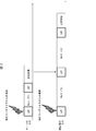
以下に、固定方式で待機時間が設定された場合の、ゲート用R/W2および棚管理用R/W3におけるRFIDタグ4との通信シーケンスの具体例について説明する。図3は、固定方式で待機時間が設定された場合において、ゲート用R/W2および棚管理用R/W3が同じタイミングで通信指示を受領し、その時点で他のリーダライタからの電波が検出された場合の通信シーケンス例を示すタイミングチャートである。
以下に、固定方式で待機時間が設定された場合の、ゲート用R/W2および棚管理用R/W3におけるRFIDタグ4との通信シーケンスの具体例について説明する。図3は、固定方式で待機時間が設定された場合において、ゲート用R/W2および棚管理用R/W3が同じタイミングで通信指示を受領し、その時点で他のリーダライタからの電波が検出された場合の通信シーケンス例を示すタイミングチャートである。
ゲート用R/W2および棚管理用R/W3において、通信指示受領時点でLBTが行われる。このLBTにおいて他のリーダライタからの電波が検出されたため、待機処理が行われる。ゲート用R/W2においては待機処理がT1の期間で行われ、その後再度LBTが行われる。この時点では、他のリーダライタからの電波が検出されないため、LBT終了後に交信処理が行われる。
一方、棚管理用R/W3において、通信指示受領時点でLBTが行われる。このLBTにおいて他のリーダライタからの電波が検出されたため、待機処理が行われる。棚管理用R/W3においては待機処理がT1よりも長いT2の期間で行われ、その後再度LBTが行われる。この時点では、ゲート用R/W2において交信処理が行われているため、ゲート用R/W2からの電波がLBTにおいて検出される。よって、続いて待機処理がT2の期間で行われる。その後再度LBTが行われ、この時点では、他のリーダライタからの電波が検出されないため、LBT終了後に交信処理が行われる。
以上のように、ゲート用R/W2の待機時間が、棚管理用R/W3の待機時間よりも短く設定されていることにより、ゲート用R/W2の交信処理が優先的に実行されることがわかる。
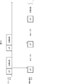
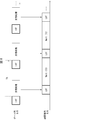
図4は、固定方式で待機時間が設定された場合において、他のリーダライタから電波が出されていない場合の通信シーケンス例を示すタイミングチャートである。
この例では、まずゲート用R/W2が先にLBTを開始している。このLBTにおいて他のリーダライタからの電波が検出されないため、ゲート用R/W2は交信処理を開始する。一方、棚管理用R/W3は、ゲート用R/W2から少し遅れてLBTを開始し、LBTの途中でゲート用R/W2からの電波を検出する。よって、棚管理用R/W3では、待機処理がT2の期間で行われる。
その後、ゲート用R/W2において、1回目の交信処理が終了した後に、2回目の交信処理を行うためにLBTが行われる。このLBTにおいて他のリーダライタからの電波が検出されないため、ゲート用R/W2は2回目の交信処理を開始する。一方、棚管理用R/W3は、待機処理の終了後にLBTを再度行い、LBTの途中でゲート用R/W2からの電波を再度検出する。よって、棚管理用R/W3では、再度待機処理がT2の期間で行われる。その後再度LBTが行われ、この時点では、他のリーダライタからの電波が検出されないため、LBT終了後に交信処理が行われる。
以上のように、図4に示す例においてもゲート用R/W2の交信処理が優先的に実行されることがわかる。
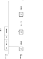
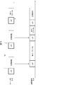
図5は、固定方式で待機時間が設定された場合において、他のリーダライタから電波が出されていない場合の他の通信シーケンス例を示すタイミングチャートである。
この例では、まず棚管理用R/W3が先にLBTを開始している。このLBTにおいて他のリーダライタからの電波が検出されないため、棚管理用R/W3は交信処理を開始する。一方、ゲート用R/W2は、棚管理用R/W3から少し遅れてLBTを開始し、LBTの途中で棚管理用R/W3からの電波を検出する。よって、ゲート用R/W2では、待機処理がT1の期間で行われる。
その後、ゲート用R/W2において、待機処理の後にLBTが再度行われ、この時点では、他のリーダライタからの電波が検出されないため、LBT終了後に交信処理が行われる。
一方、棚管理用R/W3において、1回目の交信処理が終了した後に、2回目の交信処理を行うためにLBTが行われる。このLBTの途中で棚管理用R/W3はゲート用R/W2からの電波を検出する。よって、棚管理用R/W3では、待機処理がT2の期間で行われる。その後再度LBTが行われ、この時点では、他のリーダライタからの電波が検出されないため、LBT終了後に交信処理が行われる。
以上のように、図5に示す例では、棚管理用R/W3が先にLBTを開始して交信処理を行った状況であっても、その後にゲート用R/W2が通信権を取得して交信処理を行っている。これは、ゲート用R/W2の待機時間が棚管理用R/W3の待機時間よりも短く設定されていることにより、通信権を取得する確率が高まっているからである。すなわち、図5に示す例においてもゲート用R/W2の交信処理が優先的に実行されることがわかる。
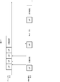
図6は、ゲート用R/W2の待機時間を0とした固定方式で待機時間が設定された場合において、ゲート用R/W2および棚管理用R/W3が同じタイミングで通信指示を受領し、その時点で他のリーダライタからの電波が検出された場合の通信シーケンス例を示すタイミングチャートである。
この例では、ゲート用R/W2の待機時間が0に設定されている。ゲート用R/W2および棚管理用R/W3において、通信指示受領時点でLBTが行われる。このLBTにおいて他のリーダライタからの電波が検出されたため、待機時間が0であることによりLBTが連続して行われる。3回目のLBTの時点では、他のリーダライタからの電波が検出されなくなったため、LBT終了後に交信処理が行われる。
一方、棚管理用R/W3において、通信指示受領時点でLBTが行われる。このLBTにおいて他のリーダライタからの電波が検出されたため、待機処理が行われる。棚管理用R/W3においては待機処理がT2の期間で行われ、その後再度LBTが行われる。この時点では、ゲート用R/W2において交信処理が行われているため、ゲート用R/W2からの電波がLBTにおいて検出される。よって、続いて待機処理がT2の期間で行われる。その後再度LBTが行われ、この時点では、他のリーダライタからの電波が検出されないため、LBT終了後に交信処理が行われる。
以上のように、ゲート用R/W2の待機時間を0に設定した場合においても、ゲート用R/W2の交信処理が優先的に実行されることがわかる。
図7は、ゲート用R/W2の待機時間を0とした固定方式で待機時間が設定された場合において、他のリーダライタから電波が出されていない場合の通信シーケンス例を示すタイミングチャートである。
この例では、まず棚管理用R/W3が先にLBTを開始している。このLBTにおいて他のリーダライタからの電波が検出されないため、棚管理用R/W3は交信処理を開始する。一方、ゲート用R/W2は、棚管理用R/W3から少し遅れてLBTを開始し、LBTの途中で棚管理用R/W3からの電波を検出する。よって、ゲート用R/W2では、棚管理用R/W3による交信処理が行われている期間において、待機時間が0であることによりLBTが連続して行われる。
その後、棚管理用R/W3における交信処理が終了すると、ゲート用R/W2におけるLBTにおいて他のリーダライタからの電波が検出されないため、LBT終了後に交信処理が行われる。
一方、棚管理用R/W3において、1回目の交信処理が終了した後に、2回目の交信処理を行うためにLBTが行われる。このLBTの途中で棚管理用R/W3はゲート用R/W2からの電波を検出する。よって、棚管理用R/W3では、待機処理がT2の期間で行われる。その後再度LBTが行われ、この時点では、他のリーダライタからの電波が検出されないため、LBT終了後に交信処理が行われる。
以上のように、図7に示す例においてもゲート用R/W2の交信処理が優先的に実行されることがわかる。
なお、ゲート用R/W2の待機時間を0に設定した場合において、図4と同様にゲート用R/W2が先にLBTを開始した場合、通信シーケンスとしては図4と同様となる。
ここで、ゲート用R/W2の交信周期TAが、棚管理用R/W3の待機時間と一致した場合に生じる問題について説明する。図8は、固定方式で待機時間が設定された場合において、他のリーダライタから電波が出されていない場合のさらに他の通信シーケンス例を示すタイミングチャートである。
この例では、上述したように、ゲート用R/W2の交信周期TAが、棚管理用R/W3の待機時間と一致している。この場合、棚管理用R/W3のLBT開始タイミングによっては、棚管理用R/W3が永遠に通信権を得ることができないことになる。すなわち、図6に示すように、棚管理用R/W3は、ゲート用R/W2の交信処理期間においてLBTを行うと、ゲート用R/W2からの電波を検出することにより待機処理がT2の期間で行われる。ここで、待機時間T2が交信周期TAと一致していることにより、棚管理用R/W3における待機処理後のLBTが、ゲート用R/W2の次の交信処理のタイミングと毎回重なることになる。なお、この現象は、優先度の高低に拘わらず、交信周期が一定のリーダライタがあり、それ以外のリーダライタにおける待機時間が更新周期と一致している場合に発生しうる。
すなわち、固定方式で待機時間が設定される場合、状況によっては上記のような現象が発生するという問題がある。この問題を解決する手法として、以下にランダム方式で待機時間を設定する例について説明する。
(ランダム方式による通信シーケンスの具体例)
以下に、ランダム方式で待機時間が設定された場合の、ゲート用R/W2および棚管理用R/W3におけるRFIDタグ4との通信シーケンスの具体例について説明する。図9は、ランダム方式で待機時間が設定された場合において、他のリーダライタから電波が出されていない場合の通信シーケンス例を示すタイミングチャートである。
以下に、ランダム方式で待機時間が設定された場合の、ゲート用R/W2および棚管理用R/W3におけるRFIDタグ4との通信シーケンスの具体例について説明する。図9は、ランダム方式で待機時間が設定された場合において、他のリーダライタから電波が出されていない場合の通信シーケンス例を示すタイミングチャートである。
この例では、棚管理用R/W3は、ゲート用R/W2の交信処理期間においてLBTを行うと、ゲート用R/W2からの電波を検出することにより待機処理が行われる。この待機処理の時間としてはT5~T6の間の時間がランダムに設定される。
その後、ゲート用R/W2は、交信周期TA後に2回目の交信処理を行う。この交信処理のタイミングで、棚管理用R/W3が待機処理後にLBTを行い、ゲート用R/W2の電波を検出することによって再度待機処理が行われる。この待機処理の時間としてはT5~T6の間の時間がランダムに設定される。この待機処理後に、棚管理用R/W3はLBTを行う。このタイミングではゲート用R/W2は交信処理を行っていないため、棚管理用R/W3はLBT後に交信処理を行う。一方、ゲート用R/W2は、次の交信周期TA後にLBTを行い、棚管理用R/W3の電波を検出することによって待機処理が行われる。この待機処理の時間としてはT3~T4の間の時間がランダムに設定される。
以上のように、ランダム方式で待機時間が設定される場合、棚管理用R/W3の待機時間がゲート用R/W2の交信周期と一致し続けることがないため、棚管理用R/W3にも通信権が与えられる可能性が生じることになる。すなわち、ランダム方式によれば、交信周期が一定のリーダライタがある場合に、特定のリーダライタに通信権が与えられなくなるというリスクをなくすことができる。
(ランダム方式の待機時間の設定バリエーション)
ここで、ゲート用R/W2および棚管理用R/W3の待機時間のランダム値の範囲設定について説明する。上記したように、ゲート用R/W2の待機時間をT3~T4の範囲でのランダム値に設定するとともに、棚管理用R/W3の待機時間をT5~T6の範囲でのランダム値に設定する。この場合、両者のランダム値の範囲設定方式として3種類のバリエーションがある。ランダム方式1が、ゲート用R/W2の待機時間のランダム値の範囲の上限であるT4が、棚管理用R/W3の待機時間のランダム値の範囲の下限であるT5よりも小さい(T4<T5)方式である。ランダム方式2が、T4とT5とが等しい(T4=T5)方式である。ランダム方式3が、T4がT5よりも大きい(T4>T5)方式である。
ここで、ゲート用R/W2および棚管理用R/W3の待機時間のランダム値の範囲設定について説明する。上記したように、ゲート用R/W2の待機時間をT3~T4の範囲でのランダム値に設定するとともに、棚管理用R/W3の待機時間をT5~T6の範囲でのランダム値に設定する。この場合、両者のランダム値の範囲設定方式として3種類のバリエーションがある。ランダム方式1が、ゲート用R/W2の待機時間のランダム値の範囲の上限であるT4が、棚管理用R/W3の待機時間のランダム値の範囲の下限であるT5よりも小さい(T4<T5)方式である。ランダム方式2が、T4とT5とが等しい(T4=T5)方式である。ランダム方式3が、T4がT5よりも大きい(T4>T5)方式である。
ランダム方式1の場合、ゲート用R/W2の待機時間が棚管理用R/W3の待機時間よりも必ず短くなるので、ゲート用R/W2の優先度を確実に高くすることができる。ランダム方式2の場合、状況によってはゲート用R/W2の待機時間と棚管理用R/W3の待機時間とが等しくなることがありうる。すなわち、待機時間が両者で等しくなった場合には、ゲート用R/W2と棚管理用R/W3とで優先度は等しくなる。ランダム方式3の場合、状況によっては、ゲート用R/W2の待機時間が棚管理用R/W3の待機時間よりも長くなることがありうる。すなわち、ゲート用R/W2の待機時間が棚管理用R/W3の待機時間よりも長くなった場合には、ゲート用R/W2の優先度が棚管理用R/W3の優先度よりも低くなることがある。しかしながら、上記したように、T3~T4の範囲でのランダム値の平均が、T5~T6の範囲でのランダム値の平均よりも短くなるように設定されているので、ランダム方式1~3のいずれであっても、平均をとればゲート用R/W2の方が、棚管理用R/W3よりも優先度が高いことになる。
図10は、ランダム方式による待機時間の設定方式のバリエーションによる待機時間設定例を示す図である。同図の(a)は、ランダム方式1の場合に、ゲート用R/W2の待機時間が棚管理用R/W3の待機時間よりも短くなっている例を示している。同図の(b)は、ランダム方式2の場合に、ゲート用R/W2の待機時間と棚管理用R/W3の待機時間とが等しくなっている例を示している。同図の(c)は、ランダム方式3の場合に、ゲート用R/W2の待機時間が棚管理用R/W3の待機時間よりも長くなっている例を示している。
(交信処理後に待機処理を行う例)
次に、交信処理を行った後に待機処理を行う例について説明する。図11は、交信後待機処理を行う場合の、ゲート用R/W2および棚管理用R/W3におけるRFIDタグ4との通信処理の流れを示すフローチャートである。ゲート用R/W2および棚管理用R/W3は基本的な通信の処理の流れは同様であるので、ここではゲート用R/W2を例に説明する。
次に、交信処理を行った後に待機処理を行う例について説明する。図11は、交信後待機処理を行う場合の、ゲート用R/W2および棚管理用R/W3におけるRFIDタグ4との通信処理の流れを示すフローチャートである。ゲート用R/W2および棚管理用R/W3は基本的な通信の処理の流れは同様であるので、ここではゲート用R/W2を例に説明する。
S11~S14の処理は、上記した図2に示すフローチャートに関する説明におけるS1~S4の処理と同様であるので、その説明を省略する。S14における交信処理が完了すると、S15において、RF通信部22における待機部26は、交信後待機処理を行う。なお、交信処理後の待機処理の開始は、交信処理において確保された交信期間の終了時点であってもよいし、交信期間の終了時点の前に必要な交信処理が終了した時点であってもよい。
図12は、交信後待機処理を行う場合において、他のリーダライタから電波が出されていない場合の通信シーケンス例を示すタイミングチャートである。
この例では、まず棚管理用R/W3が先にLBTを開始している。このLBTにおいて他のリーダライタからの電波が検出されないため、棚管理用R/W3は交信処理を開始する。また、棚管理用R/W3は、交信処理終了後に待機処理を行う。一方、ゲート用R/W2は、棚管理用R/W3から少し遅れてLBTを開始し、LBTの途中で棚管理用R/W3からの電波を検出する。よって、ゲート用R/W2では、待機処理が行われる。
その後、ゲート用R/W2において、待機処理の後にLBTが再度行われ、この時点では、他のリーダライタからの電波が検出されないため、LBT終了後に交信処理が行われる。
一方、棚管理用R/W3において、1回目の交信処理が終了し、待機処理が完了した後に、2回目の交信処理を行うためにLBTが行われる。このLBTの途中で棚管理用R/W3はゲート用R/W2からの電波を検出する。よって、棚管理用R/W3では、待機処理が行われる。その後再度LBTが行われ、この時点では、他のリーダライタからの電波が検出されないため、LBT終了後に交信処理が行われる。
以上のように、交信処理後に待機処理が行われることにより、この待機処理期間中に他のリーダライタが通信権を獲得する可能性が生じることになる。よって、特定のリーダライタが通信権を確保しつづける可能性を低減することができる。
また、交信処理後の待機処理の待機時間を、リーダライタの優先度が高いものほど短くなるように設定してもよい。具体的には、ゲート用R/W2における交信処理後の待機処理の待機時間の平均値を、棚管理用R/W3における交信処理後の待機処理の待機時間の平均値よりも短く設定してもよい。この場合、ゲート用R/W2が通信権を取得する可能性をより高めることができる。また、上記したLBT後の待機時間と同様に、交信処理後の待機処理の待機時間を、固定値で設定してもよいし、ランダムな値として設定してもよい。
なお、LBT後の待機処理の時間を各リーダライタで等しく設定する一方、交信処理後の待機処理の時間を、リーダライタの優先度が高いものほど短くなるように設定してもよい。これによっても、優先度の高いリーダライタが通信権を獲得する可能性を高めることができる。
〔ソフトウェアによる実現例〕
ゲート用R/W2および棚管理用R/W3の制御ブロック(特に上位通信部21、RF通信部22、上位通信部31、RF通信部32)は、集積回路(ICチップ)等に形成された論理回路(ハードウェア)によって実現してもよいし、ソフトウェアによって実現してもよい。
ゲート用R/W2および棚管理用R/W3の制御ブロック(特に上位通信部21、RF通信部22、上位通信部31、RF通信部32)は、集積回路(ICチップ)等に形成された論理回路(ハードウェア)によって実現してもよいし、ソフトウェアによって実現してもよい。
後者の場合、ゲート用R/W2および棚管理用R/W3は、各機能を実現するソフトウェアであるプログラムの命令を実行するコンピュータを備えている。このコンピュータは、例えば1つ以上のプロセッサを備えていると共に、前記プログラムを記憶したコンピュータ読み取り可能な記録媒体を備えている。そして、前記コンピュータにおいて、前記プロセッサが前記プログラムを前記記録媒体から読み取って実行することにより、本発明の目的が達成される。前記プロセッサとしては、例えばCPU(Central Processing Unit)を用いることができる。前記記録媒体としては、「一時的でない有形の媒体」、例えば、ROM(Read Only Memory)等の他、テープ、ディスク、カード、半導体メモリ、プログラマブルな論理回路などを用いることができる。また、前記プログラムを展開するRAM(Random Access Memory)などをさらに備えていてもよい。また、前記プログラムは、該プログラムを伝送可能な任意の伝送媒体(通信ネットワークや放送波等)を介して前記コンピュータに供給されてもよい。なお、本発明の一態様は、前記プログラムが電子的な伝送によって具現化された、搬送波に埋め込まれたデータ信号の形態でも実現され得る。
(まとめ)
以上のように、本発明の一態様に係る通信システムは、複数のRFIDタグに対してデータの読み出しおよび書き込みの少なくともいずれか一方を行う複数のリーダライタを備える通信システムであって、各リーダライタは、他のリーダライタがRFIDタグと通信するときに発する電波を検出する検出部と、通信対象のRFIDタグと通信する前に、他のリーダライタの前記電波を検出すると、前記通信対象のRFIDタグとの通信開始を所定の待機時間で待機する処理、および、前記通信対象のRFIDタグとの交信処理が完了した後に所定の待機時間で待機する処理の少なくともいずれか一方を行う待機部とを備え、前記複数のリーダライタのうち、第1リーダライタの待機時間の平均値は、第2リーダライタの待機時間の平均値よりも短く設定されている構成である。
以上のように、本発明の一態様に係る通信システムは、複数のRFIDタグに対してデータの読み出しおよび書き込みの少なくともいずれか一方を行う複数のリーダライタを備える通信システムであって、各リーダライタは、他のリーダライタがRFIDタグと通信するときに発する電波を検出する検出部と、通信対象のRFIDタグと通信する前に、他のリーダライタの前記電波を検出すると、前記通信対象のRFIDタグとの通信開始を所定の待機時間で待機する処理、および、前記通信対象のRFIDタグとの交信処理が完了した後に所定の待機時間で待機する処理の少なくともいずれか一方を行う待機部とを備え、前記複数のリーダライタのうち、第1リーダライタの待機時間の平均値は、第2リーダライタの待機時間の平均値よりも短く設定されている構成である。
また、本発明の一態様に係る通信システムの通信方法は、複数のRFIDタグに対してデータの読み出しおよび書き込みの少なくともいずれか一方を行う複数のリーダライタを備える通信システムにおける通信方法であって、各リーダライタは、他のリーダライタがRFIDタグと通信するときに発する電波を検出する検出ステップと、通信対象のRFIDタグと通信する前に、他のリーダライタの前記電波を検出すると、前記通信対象のRFIDタグとの通信開始を所定の待機時間で待機する処理、および、前記通信対象のRFIDタグとの交信処理が完了した後に所定の待機時間で待機する処理の少なくともいずれか一方を行う待機ステップとを含み、前記複数のリーダライタのうち、第1リーダライタの待機時間の平均値は、第2リーダライタの待機時間の平均値よりも短く設定されている方法である。
上記の構成または方法によれば、第1リーダライタの待機時間の平均値は、第2リーダライタの待機時間の平均値よりも短く設定されているので、第1リーダライタが通信権を取得する可能性を高くすることができる。よって、第1リーダライタに対して第2リーダライタよりも通信の優先度を高く設定することができる。
また、優先度の設定は、それぞれのリーダライタにおける待機時間を設定することによって実現できるので、上位システムによる制御が不要であり、システムの複雑化を招くことなく実現できる。
本発明の一態様に係る通信システムは、上記の構成において、前記第1リーダライタの前記待機部は、待機時間を0とする構成としてもよい。
上記の構成によれば、第1リーダライタの優先度を最も高くし、かつ、待機時間がなく迅速に交信処理を開始することができる。
本発明の一態様に係る通信システムは、上記の構成において、前記第1リーダライタの前記待機部は、待機する毎に、T3以上T4以下の範囲からランダムに待機時間を決定する構成としてもよい。
上記の構成によれば、例えば特定のリーダライタが所定の交信周期で交信する場合に、交信周期と待機時間とが等しくなることによって、第1リーダライタが通信権を取得する機会が完全に失われるような状況を防止することができる。
本発明の一態様に係る通信システムは、上記の構成において、前記第2リーダライタの前記待機部は、待機する毎に、T5以上T6以下の範囲からランダムに待機時間を決定する構成としてもよい。
上記の構成によれば、例えば特定のリーダライタが所定の交信周期で交信する場合に、交信周期と待機時間とが等しくなることによって、第2リーダライタが通信権を取得する機会が完全に失われるような状況を防止することができる。
本発明の一態様に係る通信システムは、上記の構成において、前記第2リーダライタの前記待機部は、待機する毎に、T5以上T6以下の範囲からランダムに待機時間を決定し、前記T4が前記T5よりも小さい値である、構成としてもよい。
上記の構成によれば、第1リーダライタの待機時間が第2リーダライタの待機時間よりも必ず短くなるので、第1リーダライタの優先度を確実に高くすることができる。
本発明の一態様に係る通信システムは、上記の構成において、前記第2リーダライタの前記待機部は、待機する毎に、T5以上T6以下の範囲からランダムに待機時間を決定し、前記T4が前記T5と等しい値である構成としてもよい。
上記の構成によれば、状況によっては第1リーダライタの待機時間と第2リーダライタの待機時間とが等しくなることがあり、この場合には、第1リーダライタと第2リーダライタとで優先度を等しくすることができる。
本発明の一態様に係る通信システムは、上記の構成において、前記第2リーダライタの前記待機部は、待機する毎に、T5以上T6以下の範囲からランダムに待機時間を決定し、前記T4が前記T5よりも大きい値である構成としてもよい。
上記の構成によれば、状況によっては、第1リーダライタの待機時間が第2リーダライタの待機時間よりも長くなることがあり、この場合には、第1リーダライタの優先度が第2リーダライタの優先度よりも低くなることがある。すなわち、第1リーダライタの優先度を弱く設定することができる。
本発明の一態様に係る通信システムは、上記の構成において、前記第1リーダライタは、自身の配置位置が固定されているとともに、通信領域を通過するRFIDタグと通信を行うものであり、前記第2リーダライタは、自身が移動することにより、移動していないRFIDタグと通信を行うものである構成としてもよい。
上記の構成では、第1リーダライタは、移動するRFIDタグと限られた時間内で通信を行う必要がある。一方、第2リーダライタは、移動していないRFIDタグと通信すればよく、時間的な制限はない。よって、このようなシステムにおいて、第1リーダライタに適切に優先度を高く設定することができるため、通信権の付与を好ましい状態で実現することが可能となる。
本発明は上述した各実施形態に限定されるものではなく、請求項に示した範囲で種々の変更が可能であり、異なる実施形態にそれぞれ開示された技術的手段を適宜組み合わせて得られる実施形態についても本発明の技術的範囲に含まれる。
1 PLC
2 ゲート用R/W(第1リーダライタ)
3 棚管理用R/W(第2リーダライタ)
4 RFIDタグ
5 搬送車
21、31 上位通信部
22、32 RF通信部
23、33 アンテナ
26、36 待機部
27、37 検出部
34 トリガースイッチ
100 通信システム
2 ゲート用R/W(第1リーダライタ)
3 棚管理用R/W(第2リーダライタ)
4 RFIDタグ
5 搬送車
21、31 上位通信部
22、32 RF通信部
23、33 アンテナ
26、36 待機部
27、37 検出部
34 トリガースイッチ
100 通信システム
Claims (9)
- 複数のRFIDタグに対してデータの読み出しおよび書き込みの少なくともいずれか一方を行う複数のリーダライタを備える通信システムであって、
各リーダライタは、
他のリーダライタがRFIDタグと通信するときに発する電波を検出する検出部と、
通信対象のRFIDタグと通信する前に、他のリーダライタの前記電波を検出すると、前記通信対象のRFIDタグとの通信開始を所定の待機時間で待機する処理、および、
前記通信対象のRFIDタグとの交信処理が完了した後に所定の待機時間で待機する処理の少なくともいずれか一方を行う待機部とを備え、
前記複数のリーダライタのうち、第1リーダライタの待機時間の平均値は、第2リーダライタの待機時間の平均値よりも短く設定されている、通信システム。 - 前記第1リーダライタの前記待機部は、待機時間を0とする、請求項1に記載の通信システム。
- 前記第1リーダライタの前記待機部は、待機する毎に、T3以上T4以下の範囲からランダムに待機時間を決定する、請求項1に記載の通信システム。
- 前記第2リーダライタの前記待機部は、待機する毎に、T5以上T6以下の範囲からランダムに待機時間を決定する、請求項1~3のいずれか一項に記載の通信システム。
- 前記第2リーダライタの前記待機部は、待機する毎に、T5以上T6以下の範囲からランダムに待機時間を決定し、前記T4が前記T5よりも小さい値である、請求項3に記載の通信システム。
- 前記第2リーダライタの前記待機部は、待機する毎に、T5以上T6以下の範囲からランダムに待機時間を決定し、前記T4が前記T5と等しい値である、請求項3に記載の通信システム。
- 前記第2リーダライタの前記待機部は、待機する毎に、T5以上T6以下の範囲からランダムに待機時間を決定し、前記T4が前記T5よりも大きい値である、請求項3に記載の通信システム。
- 前記第1リーダライタは、自身の配置位置が固定されているとともに、通信領域を通過するRFIDタグと通信を行うものであり、
前記第2リーダライタは、自身が移動することにより、移動していないRFIDタグと通信を行うものである、請求項1から7のいずれか一項に記載の通信システム。 - 複数のRFIDタグに対してデータの読み出しおよび書き込みの少なくともいずれか一方を行う複数のリーダライタを備える通信システムにおける通信方法であって、
各リーダライタは、
他のリーダライタがRFIDタグと通信するときに発する電波を検出する検出ステップと、
通信対象のRFIDタグと通信する前に、他のリーダライタの前記電波を検出すると、前記通信対象のRFIDタグとの通信開始を所定の待機時間で待機する処理、および、
前記通信対象のRFIDタグとの交信処理が完了した後に所定の待機時間で待機する処理の少なくともいずれか一方を行う待機ステップとを含み、
前記複数のリーダライタのうち、第1リーダライタの待機時間の平均値は、第2リーダライタの待機時間の平均値よりも短く設定されている、通信システムにおける通信方法。
Priority Applications (2)
| Application Number | Priority Date | Filing Date | Title |
|---|---|---|---|
| DE112020001229.8T DE112020001229T5 (de) | 2019-03-14 | 2020-02-06 | Kommunikationssystem und kommunikationsverfahren für das kommunikationssystem |
| CN202080013372.1A CN113412487B (zh) | 2019-03-14 | 2020-02-06 | 通信系统及通信系统的通信方法 |
Applications Claiming Priority (2)
| Application Number | Priority Date | Filing Date | Title |
|---|---|---|---|
| JP2019047218A JP7021654B2 (ja) | 2019-03-14 | 2019-03-14 | 通信システムおよび通信システムの通信方法 |
| JP2019-047218 | 2019-03-14 |
Publications (1)
| Publication Number | Publication Date |
|---|---|
| WO2020184008A1 true WO2020184008A1 (ja) | 2020-09-17 |
Family
ID=72426751
Family Applications (1)
| Application Number | Title | Priority Date | Filing Date |
|---|---|---|---|
| PCT/JP2020/004545 Ceased WO2020184008A1 (ja) | 2019-03-14 | 2020-02-06 | 通信システムおよび通信システムの通信方法 |
Country Status (4)
| Country | Link |
|---|---|
| JP (1) | JP7021654B2 (ja) |
| CN (1) | CN113412487B (ja) |
| DE (1) | DE112020001229T5 (ja) |
| WO (1) | WO2020184008A1 (ja) |
Cited By (1)
| Publication number | Priority date | Publication date | Assignee | Title |
|---|---|---|---|---|
| JP7741488B2 (ja) | 2018-07-12 | 2025-09-18 | 株式会社Flosfia | 半導体装置 |
Families Citing this family (2)
| Publication number | Priority date | Publication date | Assignee | Title |
|---|---|---|---|---|
| JP7041374B2 (ja) | 2020-09-04 | 2022-03-24 | ダイキン工業株式会社 | 生成方法、プログラム、情報処理装置、情報処理方法、及び学習済みモデル |
| JP7557513B2 (ja) * | 2022-12-02 | 2024-09-27 | キヤノン株式会社 | 通信装置、通信装置の制御方法及びプログラム |
Citations (2)
| Publication number | Priority date | Publication date | Assignee | Title |
|---|---|---|---|---|
| WO2007026412A1 (ja) * | 2005-08-31 | 2007-03-08 | Mitsubishi Denki Kabushiki Kaisha | 通信局装置及び通信方法及び通信局装置システム |
| JP2009251630A (ja) * | 2008-04-01 | 2009-10-29 | Panasonic Corp | Rfid管理システム、rfidリーダ装置、rfid同期制御装置、rfid管理装置およびrfid管理方法 |
Family Cites Families (8)
| Publication number | Priority date | Publication date | Assignee | Title |
|---|---|---|---|---|
| EP1964416A4 (en) * | 2005-12-21 | 2015-05-06 | Symbol Technologies Inc | OPTIMIZED OPERATION OF A HIGH-DENSITY READER SYSTEM FOR IMPROVED LBT (LISTENING TO TALK) COMMUNICATIONS |
| JP5094198B2 (ja) | 2006-04-28 | 2012-12-12 | 株式会社半導体エネルギー研究所 | 管理サーバ、記録媒体 |
| JP4518053B2 (ja) * | 2006-08-31 | 2010-08-04 | 株式会社デンソーウェーブ | Rfタグリーダおよびrfタグシステム |
| JP4893211B2 (ja) * | 2006-10-04 | 2012-03-07 | 株式会社デンソーウェーブ | Rfタグシステムおよびrfタグリーダの制御装置 |
| JP5118858B2 (ja) * | 2007-02-06 | 2013-01-16 | 株式会社ユニバーサルエンターテインメント | 制御装置、無線icタグ読み取りシステム、並びに無線icタグ読み取り装置 |
| CN101093549B (zh) * | 2007-07-27 | 2010-06-09 | 北京华大恒泰科技有限责任公司 | 射频识别系统的读写器的数据读取及标签的数据发送方法 |
| CN105117744B (zh) * | 2015-06-30 | 2018-06-22 | 江苏军一物联网股份有限公司 | 一种采用超高频rfid读写器进行自组网通信的方法 |
| JP6694316B2 (ja) * | 2016-04-06 | 2020-05-13 | 東芝テック株式会社 | 無線タグ通信システム |
-
2019
- 2019-03-14 JP JP2019047218A patent/JP7021654B2/ja active Active
-
2020
- 2020-02-06 WO PCT/JP2020/004545 patent/WO2020184008A1/ja not_active Ceased
- 2020-02-06 CN CN202080013372.1A patent/CN113412487B/zh active Active
- 2020-02-06 DE DE112020001229.8T patent/DE112020001229T5/de active Pending
Patent Citations (2)
| Publication number | Priority date | Publication date | Assignee | Title |
|---|---|---|---|---|
| WO2007026412A1 (ja) * | 2005-08-31 | 2007-03-08 | Mitsubishi Denki Kabushiki Kaisha | 通信局装置及び通信方法及び通信局装置システム |
| JP2009251630A (ja) * | 2008-04-01 | 2009-10-29 | Panasonic Corp | Rfid管理システム、rfidリーダ装置、rfid同期制御装置、rfid管理装置およびrfid管理方法 |
Cited By (1)
| Publication number | Priority date | Publication date | Assignee | Title |
|---|---|---|---|---|
| JP7741488B2 (ja) | 2018-07-12 | 2025-09-18 | 株式会社Flosfia | 半導体装置 |
Also Published As
| Publication number | Publication date |
|---|---|
| CN113412487A (zh) | 2021-09-17 |
| JP2020149445A (ja) | 2020-09-17 |
| CN113412487B (zh) | 2024-04-09 |
| JP7021654B2 (ja) | 2022-02-17 |
| DE112020001229T5 (de) | 2022-01-05 |
Similar Documents
| Publication | Publication Date | Title |
|---|---|---|
| CN103514464B (zh) | 一种基于多信道的rfid多标签读写识别方法及装置 | |
| JP7021654B2 (ja) | 通信システムおよび通信システムの通信方法 | |
| US20080278290A1 (en) | Radio Frequency Identification (RFID) System for Dynamically and Automatically Establishing Communication Between A Mobile Wireless Communicating Device and A Processing System | |
| JP6098260B2 (ja) | Rfidシステム、交信装置および交信プログラム | |
| CN105468548B (zh) | 串行外围接口的通信 | |
| US9990317B2 (en) | Full-mask partial-bit-field (FM-PBF) technique for latency sensitive masked-write | |
| US8174365B2 (en) | IC tag, method of controlling the IC tag, and IC tag system | |
| EP2801930A1 (en) | A near field communication reader adapted for NFC A anti collision and a method of NFC A anti collision | |
| US9514067B2 (en) | Interface arbitration for a wired tag | |
| JP4685926B2 (ja) | 改良型トランスポンダ | |
| TWI384402B (zh) | 射頻識別標籤的存取方法以及射頻識別標籤中用來判斷是否回應讀取器所發送之指令的電路 | |
| JP2001143023A (ja) | 非接触式icカードリーダライタ | |
| EP2911066B1 (en) | Method of transferring data, computer program product and tag | |
| US20090102675A1 (en) | Centralized RFID Reader Control and Coordination | |
| US20070069865A1 (en) | IC tag, IC tag system, and data communicating method for the IC tag | |
| US7907905B2 (en) | Radio frequency management system | |
| JP5715979B2 (ja) | 通信装置、および通信方法 | |
| JP7010256B2 (ja) | 情報処理装置、リーダライタ、サイドローブ通過判定方法、制御プログラム | |
| US20170341876A1 (en) | Communication device and system including communication device | |
| JP5143464B2 (ja) | データ読取装置及びデータ読取システム並びにデータ読取方式 | |
| US12524633B2 (en) | Communication apparatus that communicates tag information with another communication apparatus | |
| JP4490882B2 (ja) | 無線タグ用リーダライタ | |
| CN112639799B (zh) | 射频识别通信系统及射频识别通信系统的控制方法 | |
| JP7338494B2 (ja) | Rfidタグの読み取り方法及びrfidリーダシステム | |
| US11677444B2 (en) | Contactless transponder and method |
Legal Events
| Date | Code | Title | Description |
|---|---|---|---|
| 121 | Ep: the epo has been informed by wipo that ep was designated in this application |
Ref document number: 20771060 Country of ref document: EP Kind code of ref document: A1 |
|
| 122 | Ep: pct application non-entry in european phase |
Ref document number: 20771060 Country of ref document: EP Kind code of ref document: A1 |