WO2020183930A1 - 印加装置及び印加方法 - Google Patents
印加装置及び印加方法 Download PDFInfo
- Publication number
- WO2020183930A1 WO2020183930A1 PCT/JP2020/002363 JP2020002363W WO2020183930A1 WO 2020183930 A1 WO2020183930 A1 WO 2020183930A1 JP 2020002363 W JP2020002363 W JP 2020002363W WO 2020183930 A1 WO2020183930 A1 WO 2020183930A1
- Authority
- WO
- WIPO (PCT)
- Prior art keywords
- application
- heat
- temperature
- electrical stimulation
- control unit
- Prior art date
- Legal status (The legal status is an assumption and is not a legal conclusion. Google has not performed a legal analysis and makes no representation as to the accuracy of the status listed.)
- Ceased
Links
Images




Classifications
-
- A—HUMAN NECESSITIES
- A61—MEDICAL OR VETERINARY SCIENCE; HYGIENE
- A61F—FILTERS IMPLANTABLE INTO BLOOD VESSELS; PROSTHESES; DEVICES PROVIDING PATENCY TO, OR PREVENTING COLLAPSING OF, TUBULAR STRUCTURES OF THE BODY, e.g. STENTS; ORTHOPAEDIC, NURSING OR CONTRACEPTIVE DEVICES; FOMENTATION; TREATMENT OR PROTECTION OF EYES OR EARS; BANDAGES, DRESSINGS OR ABSORBENT PADS; FIRST-AID KITS
- A61F7/00—Heating or cooling appliances for medical or therapeutic treatment of the human body
-
- A—HUMAN NECESSITIES
- A61—MEDICAL OR VETERINARY SCIENCE; HYGIENE
- A61F—FILTERS IMPLANTABLE INTO BLOOD VESSELS; PROSTHESES; DEVICES PROVIDING PATENCY TO, OR PREVENTING COLLAPSING OF, TUBULAR STRUCTURES OF THE BODY, e.g. STENTS; ORTHOPAEDIC, NURSING OR CONTRACEPTIVE DEVICES; FOMENTATION; TREATMENT OR PROTECTION OF EYES OR EARS; BANDAGES, DRESSINGS OR ABSORBENT PADS; FIRST-AID KITS
- A61F7/00—Heating or cooling appliances for medical or therapeutic treatment of the human body
- A61F7/08—Warming pads, pans or mats; Hot-water bottles
-
- A—HUMAN NECESSITIES
- A61—MEDICAL OR VETERINARY SCIENCE; HYGIENE
- A61N—ELECTROTHERAPY; MAGNETOTHERAPY; RADIATION THERAPY; ULTRASOUND THERAPY
- A61N1/00—Electrotherapy; Circuits therefor
- A61N1/18—Applying electric currents by contact electrodes
- A61N1/32—Applying electric currents by contact electrodes alternating or intermittent currents
- A61N1/36—Applying electric currents by contact electrodes alternating or intermittent currents for stimulation
Definitions
- the present disclosure relates to an application device and an application method.
- Patent Documents 1 and 2 by applying a weak current as an electrical stimulus and heat to a living body or a living body tissue, a neurodegenerative disease, a cancer disease, xeroderma pigmentosum, and systemic A device for treating diseases such as autoimmune diseases and organ-specific autoimmune diseases is disclosed.
- the above-mentioned device be miniaturized so that it can be easily used by a user at home, for example.
- a battery or the like that supplies electric power.
- small batteries may not have a sufficiently high output.
- the heater used for applying heat requires a large current for heat generation. Therefore, it is originally desired that an electric stimulus is applied at a constant intensity in treatment, but in a device equipped with a small battery, the output intensity of the electric stimulus is not stable due to the consumption of electric current by the heat generation of the heater. In some cases.
- An object of the present disclosure is to provide an application device and an application method capable of further stabilizing the intensity of the applied electrical stimulation when applying the electrical stimulation and heat to a living body or a living tissue.
- the application device as the first aspect of the present disclosure is an application device that applies electrical stimulation and heat to a living body or a living tissue, and is a temperature measuring unit for measuring temperature, and the electrical stimulation and the heat.
- the control unit includes a control unit that controls application to a living body or a living tissue, and the control unit applies the heat when the temperature measured by the temperature measurement unit reaches a predetermined upper limit temperature due to the application of the heat.
- a predetermined lower limit temperature lower than the upper limit temperature while the electric stimulus is applied.
- the application of the electric stimulus is stopped, the application of the heat is started, and when the electric stimulus and the application of the heat satisfy a predetermined condition, the application of the electric stimulus and the heat is stopped.
- control unit stops the application of the electrical stimulation and the heat when the time for applying the electrical stimulation reaches a predetermined time.
- control unit receives the electrical stimulation and the heat when the number of times the temperature measured by the temperature measurement unit reaches the lower limit temperature reaches a predetermined number of times. Stop the application.
- the control unit stops the application of the electrical stimulation and the heat when a predetermined time elapses after the application of the electrical stimulation is first started.
- the temperature measured by the temperature measuring unit is at least one of the temperature of the heater that outputs the heat and the living body or the living body tissue.
- control unit applies the electrical stimulation as a weak pulsed direct current.
- the application method as the second aspect of the present disclosure is an application method by an application device having a temperature measuring unit for measuring temperature and capable of outputting electrical stimulation and heat, and the heat to a living body or a living tissue.
- a temperature measuring unit for measuring temperature and capable of outputting electrical stimulation and heat, and the heat to a living body or a living tissue.
- the step of stopping the application of the heat and starting the application of the electric stimulus and the electricity to the living body or the living tissue When the temperature measured by the temperature measuring unit reaches a predetermined lower limit temperature lower than the upper limit temperature while the stimulus is being applied, the application of the electrical stimulus is stopped and the application of the heat is started.
- a step of stopping the electric stimulation and the application of the heat when the electric stimulation and the application of the heat satisfy a predetermined condition.
- FIG. 1 is a schematic external perspective view of the application device 1 according to the embodiment.
- the application device 1 applies electrical stimulation to a living body or a living tissue (hereinafter, also simply referred to as “living body or the like”).
- the disease is treated by applying electrical stimulation.
- the electrical stimulus applied by the applying device 1 may be a weak electrical stimulus. In the present specification, it will be described below assuming that the electrical stimulation applied by the application device 1 is a weak electrical stimulation. However, in the present disclosure, the electrical stimulation applied by the application device 1 is not limited to a weak electrical stimulation.
- Weak electrical stimulation is a level of electrical stimulation that does not cause depolarization of the living body. Since a level of electrical stimulation that does not induce depolarization does not bring about muscle contraction or a feeling of stimulation to the living body, the user (patient) cannot sense the applied electrical stimulation.
- the electrical stimulation is applied to a living body or the like as, for example, a pulsed direct current.
- the pulsed direct current is applied at a frequency of, for example, 55 Hz.
- the pulse width of the pulsed direct current is, for example, 100 ⁇ sec.
- the electrical stimulation is not limited to this, and an appropriate electrical stimulation effective in treating a disease may be used.
- the frequency of the pulsed direct current may be other than 55 Hz
- the pulse width of the pulsed direct current may be other than 100 ⁇ sec.
- the application device 1 further heats the living body and the like. That is, the application device 1 applies heat to a living body or the like. Therefore, the application device 1 can apply electrical stimulation and heat to a living body or the like in combination. In this case, the disease is treated by applying a weak electric stimulus and heat.
- the heat is several degrees higher than the normal temperature of the living body.
- the heat may be a temperature of 38 ° C. or higher and 45 ° C. or lower, which is several degrees higher than the normal body temperature of the human body.
- the treatment by the application device 1 is performed with the application device 1 attached to at least a part of a living body or the like.
- the application device 1 is attached to a living body or the like via a sticky sheet material.
- the application device 1 is attached to a living body or the like, for example, when the user (patient) of the application device 1 inputs a predetermined operation input to the application device 1 to start the treatment by the application device 1.
- Treatment is performed by applying electrical stimulation and heat.
- the application device 1 sets the intensity of the weak electrical stimulation applied to the living body or the like before starting the actual treatment.
- the step of setting the output intensity of a weak electrical stimulus which is performed before starting the treatment, is hereinafter simply referred to as a “setting step”.
- the stage of actually performing treatment is also simply referred to as "therapeutic stage” below. Therefore, when the user of the application device 1 inputs a predetermined operation input to the application device 1 to start the treatment by the application device 1, the application device 1 executes the setting stage to perform the treatment stage. The user is treated by setting the intensity of the electrical stimulus and then performing a treatment step.
- the application device 1 is configured by combining the main body portion 10 and the application portion 20.
- the main body 10 is configured as a housing.
- the application unit 20 is formed in a flat plate shape.
- the main body portion 10 is coupled to the application portion 20 on one surface of the flat plate-shaped application portion 20.
- the surface to which the main body portion 10 is bonded is referred to as a surface.
- the surface opposite to the front surface to which the main body portion 10 is not bonded is referred to as a back surface.
- the main body 10 configured as a housing has various functional parts inside for controlling the operation of the applying device 1. Further, the main body unit 10 is provided with an input unit that receives an operation input from the user. In the example shown in FIG. 1, the main body unit 10 includes a first input unit 101a, a second input unit 101b, and a third input unit 101c as input units.
- the first input unit 101a, the second input unit 101b, and the third input unit 101c may all be configured as operation buttons (operation keys) that can be pressed, as shown in FIG. 1, for example.
- the form of the first input unit 101a, the second input unit 101b, and the third input unit 101c is not limited to the operation buttons that can be pressed.
- the number of input units included in the main body unit 10 is not limited to three.
- the arrangement of the first input unit 101a, the second input unit 101b, and the third input unit 101c is not limited to the arrangement shown in FIG.
- the first input unit 101a, the second input unit 101b, and the third input unit 101c are operation buttons that execute different functions.
- the first input unit 101a is an operation button for switching the power of the applying device 1 on and off.
- the second input unit 101b is an operation button for starting the treatment by the application device 1.
- the third input unit 101c is an operation button for the user to input the detection of the electrical stimulus. The sensing of electrical stimulation will be described later.
- the back surface of the application unit 20 is attached to a living body or the like via a sticky sheet material.
- the application unit 20 includes an electrode unit that outputs an electrical stimulus and a heater that generates heat.
- the application unit 20 applies electrical stimulation and heat to the living body or the like with the back surface attached to the living body or the like.
- FIG. 2 is an external perspective view of the application device 1 of FIG. 1 when viewed from the back surface side.
- the application unit 20 includes two electrodes, a first electrode 102a and a second electrode 102b, as an electrode unit.
- the first electrode 102a and the second electrode 102b are exposed to the outside on the back surface side.
- the electrode unit outputs an electrical stimulus by, for example, grounding one of the first electrode 102a and the second electrode 102b and changing the voltage of the other electrode.
- the application unit 20 is provided with a heater inside. That is, the application unit 20 includes a heater between the front surface and the back surface. By heating the heater, the heat is transmitted to the living body or the like with the back surface attached to the living body or the like, and the living body or the like is warmed.
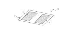
- FIG. 3 is an external perspective view showing a schematic configuration of a sheet material 30 used when the application device 1 is attached to a living body or the like.
- the sheet material 30 includes a frame portion 31 and two conductive gels 32.
- the frame portion 31 is made of a non-conductive material such as resin.
- the outer shape of the frame portion 31 is formed to be substantially the same size as the outer shape of the application portion 20.
- the frame portion 31 has two openings (through holes) for arranging the two conductive gels 32. The two openings are formed at positions corresponding to the positions where the first electrode 102a and the second electrode 102b are arranged when the sheet material 30 is attached to the back surface side of the application portion 20.
- the two conductive gels 32 are arranged in the two openings of the frame portion 31.
- the space between the two conductive gels 32 is insulated by a non-conductive frame portion 31. Since the conductive gel 32 has adhesiveness, the applying device 1 can be attached to a living body or the like.
- the two conductive gels 32 are in one-to-one contact with the first electrode 102a and the second electrode 102b, respectively.
- the application device 1 is attached to the living body or the like by the sheet material 30 and the electrical stimulation is output from the electrode portion, the electrical stimulation is applied to the living body or the like via the two conductive gels 32.
- the user replaces and uses the sheet material 30 on a regular or irregular basis. That is, the user regularly or irregularly attaches the application device 1 to a living body or the like using a new sheet material 30 and uses it. As a result, it is possible to prevent the properties of the conductive gel 32 of the sheet material 30 from changing and the conductivity from deteriorating. Further, by using the new sheet material 30, it is possible to prevent the applying device 1 from being peeled off from the living body or the like due to deterioration of the adhesiveness.
- two electrodes are arranged in one constituent device called the application unit 20.
- the first electrode 102a and the second electrode 102b may be arranged separately in different constituent devices, for example.
- the two electrodes are attached to a living body or the like as compared with the case where the two electrodes are arranged separately in different constituent devices. Since the number of constituent devices to be used can be reduced, the convenience of the user is improved.
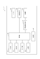
- FIG. 4 is a functional block diagram showing a schematic configuration of the application device 1 of FIG.
- the application device 1 includes an input unit 101, an electrode unit 102, a control unit 103, a display unit 104, a timer unit 105, a storage unit 106, a power supply unit 107, and a heater 108.
- a temperature measuring unit 109 and an electrical stimulation output unit 110 are provided.
- the input unit 101, the control unit 103, the display unit 104, the timer unit 105, the storage unit 106, the power supply unit 107, and the electrical stimulation output unit 110 are provided in, for example, the main body unit 10.
- the electrode unit 102, the heater 108, and the temperature measuring unit 109 are provided in, for example, the applying unit 20.
- whether each functional unit is provided in the main body unit 10 or the application unit 20 is not limited to the example shown here as long as the functions described in the present specification are exhibited.
- the input unit 101 receives an operation input from the user, and is composed of, for example, operation buttons.
- the input unit 101 is composed of three operation buttons, a first input unit 101a, a second input unit 101b, and a third input unit 101c.
- the input unit 101 may be configured by, for example, a touch screen, display an input area for receiving an operation input from the user on a part of the display device, and may accept the touch operation input by the user.
- an operation input is made to the input unit 101 by the user, for example, an electric signal corresponding to the operation input is transmitted to the control unit 103.
- the electrode unit 102 outputs an electrical stimulus based on the signal received from the electrical stimulus output unit 110.
- the electrode portion 102 is composed of two electrodes, a first electrode 102a and a second electrode 102b, for example.
- the control unit 103 controls and manages the entire application device 1 including each function unit of the application device 1.
- the control unit 103 includes at least one processor.
- the control unit 103 is composed of a processor such as a CPU (Central Processing Unit) that executes a program that defines a control procedure, or a dedicated processor that specializes in processing each function.
- the control unit 103 controls the application of electrical stimulation and heat to a living body or the like.
- control unit 103 controls the output of the electrical stimulus from the electrode unit 102.
- the control unit 103 can change the output intensity of the electrical stimulation.
- the control unit 103 can change the output intensity of the electrical stimulus by, for example, changing the magnitude of the pulsed direct current.
- the control unit 103 controls the processing of the treatment executed by the application device 1. Specifically, the control unit 103 controls the setting of the output intensity of the weak electrical stimulus in the setting stage and the treatment in the treatment stage by controlling each functional unit of the application device 1. The details of the process executed by the control unit 103 will be described later.
- control unit 103 controls the heat generation of the heater 108.
- the control unit 103 controls the application of heat to a living body or the like by controlling the heat generation of the heater 108.
- control unit 103 controls the output of the electrical stimulus and the output of the heat by the heater 108 based on the temperature measured by the temperature measuring unit 109 described later. The details of the process executed by the control unit 103 will be described later.
- the display unit 104 is a display device such as a liquid crystal display, an organic EL display, or an inorganic EL display.
- the display unit 104 is an aspect of a notification unit that notifies information.
- the display unit 104 displays various information based on the control by the control unit 103.
- the display unit 104 may display, for example, the stage of processing executed by the applying device 1, that is, the setting stage or the treatment stage.
- the display unit 104 may display, for example, the progress of treatment.
- the degree of progression of treatment is the degree of progression at the stage of treatment.
- the progress of treatment may be information indicating, for example, when the time of the treatment stage is set, how much of the time is completed.
- the display unit 104 may display the content of the detected operation input.
- the display unit 104 may display any other information to be notified to the user in relation to the treatment. Note that in FIG. 1, the display unit 104 is not shown.
- the application device 1 does not necessarily have to include the display unit 104.
- the application device 1 may include another mechanism instead of the display unit 104 or as a notification unit for notifying the user of information together with the display unit 104.
- the applying device 1 may include a speaker that notifies the user of information by sound.
- the applying device 1 may include an oscillator that notifies the user of information by vibration.
- the notification unit is not limited to the example shown here, and may be any mechanism capable of transmitting information to the user.
- the timer unit 105 measures the time based on the control of the control unit 103. For example, the timer unit 105 measures the elapsed time from the start of the treatment stage. Further, for example, the timer unit 105 measures the elapsed time after applying the electrical stimulation of the pulsed direct current.
- the storage unit 106 can be composed of a semiconductor memory, a magnetic memory, or the like.
- the storage unit 106 stores, for example, various information and a program for operating the application device 1.
- the storage unit 106 may also function as a work memory.
- the power supply unit 107 is a battery that supplies electric power to each functional unit of the application device 1.
- Heater 108 applies heat.
- the heater 108 is composed of a member that generates heat by supplying electric power, such as a heating wire.
- the heater 108 generates heat by receiving electric power from, for example, the power supply unit 107.
- the heater 108 generates heat, the heat is transmitted to the living body or the like to which the applying device 1 is attached.
- the temperature measuring unit 109 measures the temperature of the heater 108.
- the temperature measuring unit 109 is configured to include a sensor capable of detecting the temperature, such as a thermometer.
- the temperature measuring unit 109 transmits information regarding the measured temperature to the control unit 103 by transmitting an electric signal corresponding to the measured temperature to the control unit 103.
- the electrical stimulation output unit 110 outputs an electrical stimulation from the electrode unit 102 based on the control of the control unit 103.
- the application device 1 will be described as being used by being attached to the abdomen of a user who is a living body. That is, here, it is described that the treatment is performed in the abdomen of the user.
- the user attaches the application device 1 to the abdomen using the sheet material 30. Then, the user turns on the power of the applying device 1 by, for example, pressing the first input unit 101a. The user can start the treatment by the application device 1 by pressing the second input unit 101b. That is, the application device 1 starts the treatment performed by the setting stage and the treatment stage.
- FIG. 5 is a control chart schematically showing an example of control of the output of electrical stimulation and heat by the control unit 103 of FIG. 4 at the setting stage.
- FIG. 5 shows a chart of the output of the electrical stimulation and a chart of switching the heater 108 on and off.
- the horizontal axis represents time.
- the vertical axis of the electrical stimulation output chart indicates the electrical stimulation output intensity.
- the vertical axis of the chart for switching the heater 108 on and off indicates the on and off states of the heater 108. Note that FIG. 5 does not necessarily accurately describe the state of application of electrical stimulation and heat. In particular, as will be described later, in the present embodiment, the length of time that the heater 108 is in the ON state changes.
- FIG. 6 is a flowchart showing an example of processing executed by the control unit 103 of FIG. 4 at the setting stage.
- the time t 1 in FIG. 5 is the start time of the setting stage. Further, it is assumed that the heater 108 is in the off state at the start of the setting stage.
- the control unit 103 outputs the electrical stimulus from the electrode unit 102 so as to gradually increase the output intensity of the electrical stimulus. Specifically, the control unit 103 first outputs an electrical stimulus (step S10). At this time, the control unit 103 outputs the electrical stimulus at the lowest output intensity P 1 in the process of gradually increasing the output intensity of the electrical stimulus.
- the output intensity P 1 is preferably a weak electrical stimulus at a level that does not cause depolarization for almost all users. That is, the output intensity P 1 is preferably a weak electrical stimulus at a level at which almost all users do not perceive the electrical stimulus.
- the output intensity P 1 may be preset in the applying device 1. As shown in FIG. 5, the control unit 103 may output the pulsed direct current of the electrical stimulation of the output intensity P 1 a plurality of times in a predetermined cycle.
- the control unit 103 determines whether or not an input indicating that the electrical stimulus has been detected by the user has been detected when the output of the electrical stimulus in step S10 is executed (step S11). That is, the control unit 103 determines whether or not the third input unit 101c is pressed by the user when the output of the electrical stimulation in step S10 is executed.
- step S12 the control unit 103 may increase the output intensity of the electrical stimulation by, for example, a predetermined intensity range set in advance. In the example shown in FIG. 5, when the control unit 103 outputs an electrical stimulus at the output intensity P 1 and does not detect an input indicating that the electrical stimulus is detected, the control unit 103 then outputs the electrical stimulus at the output intensity P 2. doing.
- control unit 103 may start the output of the electric stimulus in the step S10 with the intensity of the electric stimulus increased in the step S12 after a predetermined time after starting the output of the electric stimulus in the step S10.
- the control unit 103 starts the output of the electrical stimulation of the output intensity P 1 in step S10 at the time t 1 , and then the electrical stimulation of the output intensity P 2 at the time t 2 after a predetermined time. Is starting to output.
- the control unit 103 repeats the increase in the intensity of the electrical stimulus in step S12 and the output of the electrical stimulus in step S10 until it is determined in step S11 that the input indicating that the electrical stimulus has been detected has been detected. By repeating this, the control unit 103 can gradually increase the output intensity of the electrical stimulation. In the example shown in FIG. 5, the control unit 103 increases the output intensity of the electrical stimulation in the order of P 1 , P 2 , P 3 , P 4 , and P 5 , and outputs the power.
- FIG time t 1 at 5, t 2, t 3, t 4 and t 5 indicates the respective output intensity P 1, P 2, P 3 , P 4 and the time that starts outputting the electrical stimulation of P 5.
- control unit 103 When the control unit 103 detects a predetermined operation input to the input unit 101, the control unit 103 sets the output intensity of the electrical stimulation used in the treatment stage.
- the output intensity of the electrical stimulus used in the treatment stage is also hereinafter referred to as "therapeutic intensity" in the present specification.
- the control unit 103 sets the treatment intensity when the operation input of pressing the third input unit 101c is detected.
- step S13 when the control unit 103 detects an input indicating that the electrical stimulus has been detected (Yes in step S11), the control unit 103 sets the treatment intensity (step S13). That is, in the present embodiment, when the control unit 103 detects an input indicating that the electrical stimulus is detected while gradually increasing the output intensity of the electrical stimulus, the control unit 103 sets the treatment intensity (step S13).
- the control unit 103 sets the treatment intensity (step S13).
- the control unit 103 when the electric stimulus is output at the output intensity P 5 , the user senses the electric stimulus and presses the third input unit 101c, and the control unit 103 indicates that the third input unit 101c is pressed. Shows an example when is detected.
- step S13 the control unit 103 is based on the output intensity of the electrical stimulus output when the control unit 103 detects a predetermined operation input to the input unit 101 (in this example, the operation input of pressing the third input unit 101c).
- a predetermined output intensity which is also low, is set as the therapeutic intensity.
- the output intensity of the electrical stimulus output when a predetermined operation input to the input unit 101 is detected is referred to as a detection output intensity Ps.
- the output intensity at the time of detection Ps P 5 is established.
- the method for setting the treatment intensity may be appropriately determined.
- the control unit 103 may set an output intensity lower than the detection output intensity Ps by a predetermined intensity as the therapeutic intensity. Further, for example, the control unit 103 may set the output intensity obtained by multiplying the detected output intensity Ps by a coefficient less than 1 as the therapeutic intensity.
- the treatment intensity setting in step S13 does not necessarily have to be executed before step S14.
- the setting of the treatment intensity in step S13 may be completed by the end of the setting step, that is, by the end of the flow of FIG.
- the control unit 103 After detecting a predetermined operation input to the input unit 101 (in this example, the operation input of pressing the third input unit 101c), the control unit 103 heats the living body or the like by the heater 108, and the heater 108 The treatment phase may be initiated when the temperature rises above a predetermined temperature. Such heating by the heater 108 may be performed at the setting stage.
- control unit 103 detects an input indicating that an electrical stimulus has been detected, sets the treatment intensity, and turns on the heater 108 (step S14).
- Chart shown in Figure 5, at time t 6, shows that the heater 108 is turned on state.
- electric power is supplied to the heater 108, and the heater 108 starts to generate heat.
- the heat generated by the heater 108 warms the abdomen of the user who is a living body.
- the control unit 103 monitors the temperature of the heater 108 based on the signal transmitted from the temperature measurement unit 109. Specifically, the control unit 103 determines whether or not the temperature of the heater 108 has reached a predetermined temperature (step S15).
- the predetermined temperature is, for example, an upper limit temperature in a temperature range suitable for treatment by the applying device 1, and may be predetermined.
- control unit 103 determines that the temperature of the heater 108 has not reached the predetermined temperature (No in step S15)
- the control unit 103 repeats step S15 while keeping the heater 108 on.
- step S15 When the control unit 103 determines that the temperature of the heater 108 has reached a predetermined temperature (Yes in step S15), the control unit 103 turns off the heater 108 (step S16). Chart shown in Figure 5, at time t 7, indicating that the heater 108 is turned off.
- the setting step ends. That is, in the chart shown in FIG. 5, the setting stage ends at time t 7 .
- the control unit 103 then starts processing in the treatment stage.
- the treatment intensity Pm may be predetermined and stored in, for example, the storage unit 106.
- the control unit 103 may execute the processing of the treatment stage by the treatment intensity Pm stored in the storage unit 106 without executing the processing of the setting stage described with reference to FIG.
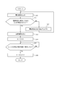
- FIG. 7 is a flowchart showing an example of processing executed by the control unit 103 in the treatment stage.
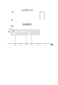
- FIG. 8 is a control chart schematically showing an example of control of electrical stimulation and thermal output by the control unit 103 and transition of the acquired temperature in the treatment stage.
- the acquired temperature is the temperature indicated by the information regarding the temperature acquired by the control unit 103 from the temperature measuring unit 109, that is, the temperature measured by the temperature measuring unit 109.
- the treatment stage may be automatically started by the control unit 103, for example, when the setting stage is completed.
- the control unit 103 stops the application of the heat and starts the application of the electrical stimulus. Further, in the treatment stage, when the temperature measured by the temperature measuring unit 109 reaches a predetermined lower limit temperature while applying the electric stimulus, the control unit 103 stops applying the electric stimulus and heats it. Is started to be applied. Since the flow of FIG. 7 is started after the flow of FIG. 6, the heater 108 is in the off state at the start of the flow of FIG. 7.
- the upper limit temperature and the lower limit temperature are the upper and lower limit temperatures of a preferable temperature range for treatment by applying an electric stimulus, respectively.
- the lower limit temperature is a temperature lower than the upper limit temperature.
- the upper limit temperature and the lower limit temperature may be appropriately determined according to the treatment method, the nature of the applied electrical stimulation, and the like.
- the upper limit temperature may be, for example, the same as the predetermined temperature in step S15 of the flow of FIG.
- it is assumed that the upper limit temperature is the same as the predetermined temperature in step S15 of the flow of FIG. In this case, as shown in FIG. 8, at time t 7 is at the beginning of the treatment phase (i.e. during the configuration phase termination), acquires the temperature is the upper limit temperature T H.
- the control unit 103 starts the output of the electrical stimulus (step S20). Specifically, the control unit 103 outputs a pulsed direct current at a predetermined cycle as an electrical stimulus. At this time, the control unit 103 outputs the electrical stimulus at the treatment intensity Pm determined in step S13 of the flow shown in FIG. Control unit 103, as shown in FIG. 8, at time t 7, starts the output of the pulse direct current. The control unit 103 continuously outputs the electrical stimulus while executing the other processes shown in the flowchart of FIG. 7 until the process of stopping the output of the electrical stimulus is executed in step S25.
- the control unit 103 starts the electrical stimulation output time timer (step S21).
- the electrical stimulation output time timer is a timer that measures the time during which the electrical stimulation is output in the treatment stage. That is, in the example here, the electrical stimulation output time timer is the time during which the output processing of the pulsed direct current is performed in the treatment stage.
- the electrical stimulation output time timer measures the total time during which the control unit 103 is performing the electrical stimulation output processing in the treatment stage. It is preferable that the control unit 103 starts the electrical stimulation output time timer in step S21 at the same time as starting the electrical stimulation output in step S20.
- the control unit 103 determines whether or not the time during which the electrical stimulus is output reaches T 1 for a predetermined time (step S22).
- the predetermined time T 1 is a treatment time, and may be set in advance, for example.
- the predetermined time T 1 is, for example, one hour.
- the treatment time is, in other words, the time during which the output processing of the electrical stimulation is performed. That is, in the present embodiment, in step S22, the control unit 103 determines whether or not the total time during which the output processing of the electrical stimulation is performed has reached the predetermined time T 1 .
- control unit 103 determines that the time during which the electrical stimulus is output has not reached T 1 for a predetermined time (No in step S22), the control unit 103 acquires information regarding the temperature transmitted from the temperature measurement unit 109 (step S23). ).
- control unit 103 determines whether or not the acquisition temperature acquired in step S23 has reached the lower limit temperature TL (step S24).
- step S24 the control unit 103 determines that the acquisition temperature has not reached the lower limit temperature TL (No in step S24).
- the control unit 103 proceeds to step S22. In this way, the control unit 103 determines that the time during which the electrical stimulus is output in step S22 has reached the predetermined time T 1 , or that the acquisition temperature has reached the lower limit temperature T L in step S24. From step S22 to step S24 is repeated.
- control unit 103 determines that the acquisition temperature has reached the lower limit temperature TL (Yes in step S24), the control unit 103 stops the output of the electrical stimulus (step S25).
- control unit 103 stops the electrical stimulation output time timer (step S26). That is, in step S25 and step S26, the control unit 103 stops the output of the electrical stimulus and temporarily stops the measurement of the time during which the output process of the electrical stimulus is being performed. It is preferable that the control unit 103 stops the output of the electrical stimulus in step S25 and at the same time stops the electrical stimulus output time timer in step S26.
- the control unit 103 turns on the heater 108 (step S27).
- the control unit 103 applies the electrical stimulus when the temperature measured by the temperature measuring unit 109 reaches a predetermined lower limit temperature TL while the electrical stimulus is applied in the treatment stage. Stop and start applying heat.
- heat is applied to the living body or the like, and the temperature measured by the temperature measuring unit 109 rises.
- the control unit 103 acquires information regarding the temperature transmitted from the temperature measurement unit 109 (step S28).
- Control unit 103 determines acquired temperature acquired in step S28 is whether or not reached the upper limit temperature T H (step S29).
- Control unit 103 if the acquired temperature is determined not to reach the upper limit temperature T H (No in step S29), and proceeds to step S28. Control unit 103 acquires the temperature in step S29 until it is determined that reaches the upper limit temperature T H, and repeats the step S28 and step S29.
- Control unit 103 if the acquired temperature is determined to have reached the upper limit temperature T H (Yes in step S29), and the OFF state of the heater (step S30). Then, the process proceeds to step S20, and the output of the electrical stimulation is started again.
- the control unit 103 in the treatment stage, the temperature measuring temperature measuring section 109 by the application of heat is, when reaching a predetermined upper limit temperature T H, and stops applying the thermal, electrical stimulation Start the application.
- step S30 from step S20.
- electrical stimulation and heat are applied alternately.
- the application of heat is stopped and the application of the electric stimulus is started at the times t 7 , t 9 and t 11 , and the application of the electric stimulus is applied at the times t 8 , t 10 and t 12.
- the application of heat is started.
- the control unit 103 stops the application of the electric stimulus and the heat. Specifically, when the control unit 103 determines in step S22 that the time for outputting the electrical stimulus reaches T 1 for a predetermined time (Yes in step S22), the control unit 103 stops the output of the electrical stimulus (step). S31). Since the heat is not applied in step S22, the control unit 103 can stop the application of the electric stimulus and the heat by stopping the output of the electric stimulus in the step S31. In this way, the flow of FIG. 7 ends. This ends the treatment phase. At this time, the control unit 103 may notify the user that the treatment stage has been completed by displaying it on the display unit 104 or driving another mechanism. When the treatment stage is completed, the user peels off the application device 1 from the abdomen to end the treatment.
- the control unit 103 when the temperature measured by the temperature measurement unit 109 due to the application of heat in the treatment stage reaches a predetermined upper limit temperature, the control unit 103 is heated. The application is stopped, the application of the electric stimulus is started, and when the temperature measured by the temperature measuring unit 109 reaches a predetermined lower limit temperature while the electric stimulus is being applied, the application of the electric stimulus is stopped. Then, the application of heat is started.
- electrical stimulation and heat are alternately applied to the living body and the like. Therefore, heat is not applied at the timing when the electrical stimulation is applied. That is, the heat is applied at the timing when the electrical stimulation is not applied.
- the power consumption for heat generation of the heater 108 does not affect the output intensity of the electric stimulus, and the output intensity of the electric stimulus can be made more stable.
- the control unit 103 stops the application of the electrical stimulation and the heat when the time for applying the electrical stimulation reaches T 1 for a predetermined time. In this way, when the application device 1 applies the electrical stimulation T 1 for a predetermined time, the application of the electrical stimulation and the heat can be automatically stopped to end the treatment.
- control unit 103 applies a weak electric stimulus to the living body or the like at the treatment stage by outputting the electric stimulus at the treatment intensity Pm lower than the output intensity Ps at the time of detection. Therefore, by inputting a predetermined operation input when the user senses the electrical stimulus, the control unit 103 outputs the electrical stimulus at the treatment stage with a strength weaker than the intensity of the electrical stimulus sensed by the user. Can be done. In this way, the application device 1 can easily set the intensity of the electrical stimulus to an appropriate level when applying a stimulus that combines a weak electrical stimulus and heat to a living body or the like.
- the control unit 103 when the output intensity of the electrical stimulus is gradually increased in the setting stage, the control unit 103 inputs a predetermined operation input when the user senses the electrical stimulus. Therefore, the treatment intensity Pm is set to be weaker than the output intensity Ps at the time of detection. As a result, the control unit 103 can set the treatment intensity Pm to a weak level that the user does not detect.
- the process executed by the control unit 103 of the application device 1 is not limited to the above-mentioned process.
- the control unit 103 may execute other processes depending on the purpose, means, method, and the like of the treatment.
- the control unit 103 stops the application of the electric stimulus and the heat when the time for applying the electric stimulus reaches T 1 for a predetermined time.
- the control unit 103 may stop the application of electrical stimulation and heat by using other determination criteria.
- the control unit 103 may stop the application of the electric stimulus and the heat when the application of the electric stimulus and the heat satisfies a predetermined condition.
- the predetermined condition may be a condition that can determine that the treatment has been completed.
- the control unit 103 may stop the application of electrical stimulation and heat when the number of times the temperature measured by the temperature measuring unit 109 reaches the lower limit temperature TL reaches a predetermined number of times in the treatment stage.
- the predetermined number of times may be appropriately determined according to the method of treatment, the nature of the applied electrical stimulation, and the like.
- the number of times the temperature measured by the temperature measuring unit 109 reaches the lower limit temperature TL corresponds to the number of times of application of the electrical stimulus from step S20 to step S25 of the flow of FIG. 7 in the treatment stage. Therefore, in this case, the control unit 103 can stop the application of the electric stimulus and the heat when the number of times of the application of the electric stimulus reaches a predetermined number of times. This also allows the application device 1 to automatically stop the application of electrical stimulation and heat to end the treatment.
- control unit 103 may stop the application of the electric stimulus and the heat when a predetermined time elapses after the application of the electric stimulus is first started in the treatment stage.
- the control unit 103 since the time when the application of the electric stimulus is first started in the treatment stage is t 7 , the control unit 103 applies the electric stimulus and the heat when a predetermined time elapses from the time t 7. You may stop. This also allows the application device 1 to automatically stop the application of electrical stimulation and heat to end the treatment.
- the temperature measuring unit 109 measures the temperature of the heater 108.
- the temperature measuring unit 109 may measure the temperature of a living body or the like.
- the temperature measuring unit 109 may measure the temperature of a place where heat is applied by the heater 108.
- the control unit 103 can more accurately determine whether the temperature of the living body or the like is appropriate for the treatment.
- the temperature measuring unit 109 may be arranged at an appropriate position where the temperature of the living body or the like can be measured in the applying device 1.
- the application device is not limited to the configuration specified in the above-described embodiment, and can be variously modified without departing from the gist of the invention described in the claims.
- the functions included in each component and each step can be rearranged so as not to be logically inconsistent, and a plurality of components or steps can be combined or divided into one. Is.
- the present disclosure relates to an application device.
Landscapes
- Health & Medical Sciences (AREA)
- Veterinary Medicine (AREA)
- Biomedical Technology (AREA)
- Life Sciences & Earth Sciences (AREA)
- Animal Behavior & Ethology (AREA)
- General Health & Medical Sciences (AREA)
- Public Health (AREA)
- Engineering & Computer Science (AREA)
- Heart & Thoracic Surgery (AREA)
- Vascular Medicine (AREA)
- Nuclear Medicine, Radiotherapy & Molecular Imaging (AREA)
- Radiology & Medical Imaging (AREA)
- Electrotherapy Devices (AREA)
- Thermotherapy And Cooling Therapy Devices (AREA)
Abstract
印加装置は、電気刺激と温熱とを生体又は生体組織に印加する印加装置であって、温度を測定する温度測定部と、前記電気刺激と前記温熱との前記生体又は生体組織への印加を制御する制御部と、を備え、前記制御部は、前記温熱の印加により前記温度測定部が測定する温度が、所定の上限温度に達した場合、前記温熱の印加を停止して、前記電気刺激の印加を開始し、前記電気刺激を印加している間に、前記温度測定部が測定する温度が、前記上限温度よりも低い所定の下限温度に達した場合、前記電気刺激の印加を停止して、前記温熱の印加を開始し、前記電気刺激及び前記温熱の印加が所定の条件を満たしたとき、前記電気刺激及び前記温熱の印加を停止する。
Description
本開示は、印加装置及び印加方法に関する。
従来、脱分極を惹起させないレベルの微弱な電気刺激と、温熱とを生体又は生体組織に印加することにより、様々な疾患の治療を行う装置が知られている。例えば、特許文献1及び特許文献2には、電気刺激としての微弱な電流と、温熱とを、生体又は生体組織に印加することにより、神経変性疾患、癌疾患、色素性乾皮症、全身性自己免疫疾患、臓器特異性自己免疫疾患等の疾患の治療を行う装置が開示されている。
上述の装置は、例えば家庭等でユーザが簡便に使用できるようにするために、小型化されることが望まれている。装置を小型化しようとすると、電力を供給するバッテリ等も小型化が必要となる。しかしながら、小型のバッテリは、出力が十分に高くない場合がある。一方で、上述の装置において、温熱を印加するために用いられるヒータは、発熱のために大きな電流を必要とする。そのため、本来は治療において一定の強度で電気刺激が印加されることが望まれるが、小型のバッテリを備える装置では、ヒータの発熱に電流が消費されることにより、電気刺激の出力強度が安定しない場合がある。
本開示の目的は、電気刺激と温熱とを生体又は生体組織に印加するに際して、印加される電気刺激の強度を、より安定させることが可能な印加装置及び印加方法を提供することである。
本開示の第1の態様としての印加装置は、電気刺激と温熱とを生体又は生体組織に印加する印加装置であって、温度を測定する温度測定部と、前記電気刺激と前記温熱との前記生体又は生体組織への印加を制御する制御部と、を備え、前記制御部は、前記温熱の印加により前記温度測定部が測定する温度が、所定の上限温度に達した場合、前記温熱の印加を停止して、前記電気刺激の印加を開始し、前記電気刺激を印加している間に、前記温度測定部が測定する温度が、前記上限温度よりも低い所定の下限温度に達した場合、前記電気刺激の印加を停止して、前記温熱の印加を開始し、前記電気刺激及び前記温熱の印加が所定の条件を満たしたとき、前記電気刺激及び前記温熱の印加を停止する。
本開示の1つの実施形態としての印加装置において、前記制御部は、前記電気刺激を印加している時間が、所定時間に達したとき、前記電気刺激及び前記温熱の印加を停止する。
本開示の1つの実施形態としての印加装置において、前記制御部は、前記温度測定部が測定する温度が前記下限温度に達した回数が、所定回数に達したとき、前記電気刺激及び前記温熱の印加を停止する。
本開示の1つの実施形態としての印加装置において、前記制御部は、最初に前記電気刺激の印加を開始してから所定時間が経過したとき、前記電気刺激及び前記温熱の印加を停止する。
本開示の1つの実施形態としての印加装置において、前記温度測定部が測定する温度は、前記温熱を出力するヒータ及び前記生体又は生体組織の少なくともいずれかの温度である。
本開示の1つの実施形態としての印加装置において、前記制御部は、前記電気刺激を、微弱なパルス直流電流として印加する。
本開示の第2の態様としての印加方法は、温度を測定する温度測定部を備え、電気刺激と温熱とを出力可能な、印加装置による印加方法であって、生体又は生体組織への前記温熱の印加により前記温度測定部が測定する温度が、所定の上限温度に達した場合、前記温熱の印加を停止して、前記電気刺激の印加を開始するステップと、前記生体又は生体組織に前記電気刺激を印加している間に、前記温度測定部が測定する温度が、前記上限温度よりも低い所定の下限温度に達した場合、前記電気刺激の印加を停止して、前記温熱の印加を開始するステップと、前記電気刺激及び前記温熱の印加が所定の条件を満たしたとき、前記電気刺激及び前記温熱の印加を停止するステップと、を含む。
本開示によれば、電気刺激と温熱とを生体又は生体組織に印加するに際して、印加される電気刺激の強度を、より安定させることが可能な印加装置及び印加方法を提供できる。
以下、本開示に係る印加装置の実施形態について図面を参照しながら説明する。各図において共通する部材には同一の符号を付している。
図1は、一実施形態に係る印加装置1の概略的な外観斜視図である。印加装置1は、電気刺激を生体又は生体組織(以下、単に「生体等」とも称する)に印加する。電気刺激の印加により、疾患の治療が行われる。印加装置1が印加する電気刺激は、微弱な電気刺激であってよい。本明細書では、印加装置1が印加する電気刺激が微弱な電気刺激であるとして、以下説明する。ただし、本開示において、印加装置1が印加する電気刺激は微弱な電気刺激に限られない。
微弱な電気刺激は、生体等に対して、脱分極を惹起させないレベルの電気刺激である。脱分極を惹起させないレベルの電気刺激は、筋収縮や刺激感を生体にもたらさないため、ユーザ(患者)は印加される電気刺激を感知することができない。電気刺激は、例えばパルス直流電流として、生体等に印加される。パルス直流電流は、例えば55Hzの周波数で印加される。パルス直流電流のパルス幅は、例えば100μ秒である。ただし、電気刺激は、これに限られず、疾患の治療に効果のある適宜の電気刺激が用いられてよい。例えば、パルス直流電流の周波数は55Hz以外であってもよく、パルス直流電流のパルス幅は100μ秒以外であってもよい。
印加装置1は、さらに生体等を加温する。すなわち、印加装置1は、生体等に対して温熱を印加する。従って、印加装置1は、電気刺激と温熱とを組み合わせて、生体等に印加することができる。この場合、微弱な電気刺激と温熱との印加により、疾患の治療が行われる。
温熱は、生体等の平常時の温度よりも数度高い温熱である。例えば、印加装置1を人体に対して適用する場合、温熱は、人体の平常時の体温よりも数度高い、38℃以上45℃以下の温度であってよい。
印加装置1による治療は、印加装置1を生体等の少なくとも一部に貼付した状態で実行される。例えば、印加装置1は、粘着性のあるシート材を介して、生体等に貼付される。印加装置1が生体等に貼付された状態で、例えば、印加装置1のユーザ(患者)が、印加装置1に対して、印加装置1による治療を開始するための所定の操作入力を行うと、電気刺激及び温熱を印加することによる治療が行われる。
ここで、本実施形態に係る印加装置1は、実際の治療を開始する前に、生体等に印加する微弱な電気刺激の強度を設定する。本明細書において、治療を開始する前に行われる、微弱な電気刺激の出力強度を設定する段階を、以下、単に「設定段階」とも称する。また、本明細書において、実際に治療を行う段階を、以下、単に「治療段階」とも称する。従って、印加装置1のユーザが、印加装置1に対して、印加装置1による治療を開始するための所定の操作入力を行うと、印加装置1は、設定段階を実行することにより、治療段階における電気刺激の強度を設定し、その後、治療段階を実行することにより、ユーザの治療を行う。
図1に示すように、印加装置1は、本体部10と印加部20とが結合されて構成される。本体部10は、筐体として構成されている。印加部20は、平板形状に構成されている。本体部10は、平板形状の印加部20の一方の面において、印加部20と結合されている。本明細書では、平板形状の印加部20において、本体部10が結合されている面を表面という。また、平板形状の印加部20において、表面とは反対側の、本体部10が結合されていない面を裏面という。
筐体として構成されている本体部10は、内部に、印加装置1の動作を制御するための各種機能部を有する。また、本体部10には、ユーザからの操作入力を受け付ける入力部が設けられている。図1に示す例では、本体部10は、入力部として、第1入力部101a、第2入力部101b及び第3入力部101cを備える。
第1入力部101a、第2入力部101b及び第3入力部101cは、例えば図1に示すように、いずれも押下可能な操作ボタン(操作キー)として構成されていてよい。ただし、第1入力部101a、第2入力部101b及び第3入力部101cの形態は、押下可能な操作ボタンに限られない。また、本体部10が備える入力部の数量は3個に限られない。さらに、第1入力部101a、第2入力部101b及び第3入力部101cの配置は、図1に示す配置に限られない。
本実施形態では、第1入力部101a、第2入力部101b及び第3入力部101cは、それぞれ異なる機能を実行させる操作ボタンである。具体的には、第1入力部101aは、印加装置1の電源のオンとオフとを切り替える操作ボタンである。第2入力部101bは、印加装置1による治療を開始させるための操作ボタンである。第3入力部101cは、ユーザが電気刺激の感知を入力するための操作ボタンである。電気刺激の感知については、後述する。
印加部20は、粘着性のあるシート材を介して、裏面が生体等に貼付される。印加部20は、電気刺激を出力する電極部と、発熱するヒータを備える。印加部20は、裏面が生体等に貼付された状態で、生体等に電気刺激と温熱とを印加する。
図2は、図1の印加装置1を裏面側から見た場合の外観斜視図である。図2に示すように、印加部20は、電極部として、第1電極102aと第2電極102bとの、2枚の電極を備える。第1電極102a及び第2電極102bは、裏面側において、外部に露出している。電極部は、例えば、第1電極102a及び第2電極102bのうち、1枚の電極を接地し、もう1枚の電極について電圧を変化させることにより、電気刺激を出力する。
印加部20は、内部にヒータを備える。すなわち、印加部20は、表面と裏面との間に、ヒータを備える。ヒータを加熱することにより、裏面が生体等に貼付された状態で、生体等に温熱が伝達されて、生体等が温められる。
図3は、印加装置1を生体等に貼付する際に用いられるシート材30の概略構成を示す外観斜視図である。シート材30は、フレーム部31と、2枚の導電性ゲル32とを備える。
フレーム部31は、例えば樹脂等の非導電性材料により構成される。フレーム部31の外形は、印加部20の外形とほぼ同じ大きさに形成されている。フレーム部31は、2枚の導電性ゲル32を配置するための2つの開口(貫通孔)を有する。2つの開口は、シート材30を印加部20の裏面側に貼付した場合に、第1電極102a及び第2電極102bが配置されている位置に一致する位置に形成されている。
2枚の導電性ゲル32は、フレーム部31の2つの開口に配置される。2枚の導電性ゲル32の間は、非導電性のフレーム部31によって絶縁されている。導電性ゲル32は、粘着性を有することにより、印加装置1を生体等に貼付することができる。シート材30が印加部20の裏面側に貼付された状態において、2枚の導電性ゲル32は、それぞれ、第1電極102a及び第2電極102bと1対1に対応して接触する。これにより、印加装置1がシート材30により生体等に貼付されて、電極部から電気刺激が出力された場合に、当該電気刺激が、2枚の導電性ゲル32を介して生体等に印加される。
ユーザは、定期的又は不定期的に、シート材30を取り替えて使用する。つまり、ユーザは、定期的又は不定期的に、新たなシート材30を用いて印加装置1を生体等に貼付して使用する。これにより、シート材30の導電性ゲル32の性質が変化して、導電性が劣化することを防ぐことができる。また、新たなシート材30を使用することにより、粘着性が劣化して印加装置1が生体等からはがれることを防ぐことができる。
なお、本実施形態では、上述したように、印加部20という1つの構成機器に、第1電極102a及び第2電極102bという2枚の電極が配置されている。しかしながら、第1電極102a及び第2電極102bは、例えば、異なる構成機器に別々に配置されていてもよい。本実施形態のように、1つの構成機器に2枚の電極が配置されている場合には、2枚の電極が異なる構成機器に別々に配置されている場合と比較して、生体等に貼付する構成機器の数量を減らすことができるため、ユーザの利便性が高まる。
図4は、図1の印加装置1の概略構成を示す機能ブロック図である。図4に示すように、印加装置1は、入力部101と、電極部102と、制御部103と、表示部104と、タイマ部105と、記憶部106と、電源部107と、ヒータ108と、温度測定部109と、電気刺激出力部110とを備える。入力部101、制御部103、表示部104、タイマ部105、記憶部106、電源部107、及び電気刺激出力部110は、例えば本体部10に設けられる。電極部102、ヒータ108、及び温度測定部109は、例えば印加部20に設けられる。ただし、各機能部が本体部10及び印加部20のいずれに設けられるかについては、本明細書に記載の機能を発揮する限り、ここで示した例に限られない。
入力部101は、ユーザからの操作入力を受け付けるものであり、例えば、操作ボタンにより構成される。本実施形態では、入力部101は、上述したように、第1入力部101a、第2入力部101b及び第3入力部101cという3つの操作ボタンにより構成される。なお、入力部101は、例えばタッチスクリーンにより構成され、表示デバイスの一部にユーザからの操作入力を受け付ける入力領域を表示して、ユーザによるタッチ操作入力を受け付けてもよい。ユーザにより、入力部101に対する操作入力が行われると、例えば操作入力に応じた電気信号が制御部103に送信される。
電極部102は、電気刺激出力部110から受信した信号に基づき、電気刺激を出力する。電極部102は、例えば上述したように、第1電極102a及び第2電極102bという2枚の電極により構成される。
制御部103は、印加装置1の各機能部をはじめとして、印加装置1の全体を制御及び管理する。制御部103は、少なくとも1つのプロセッサを含んで構成される。制御部103は、制御手順を規定したプログラムを実行するCPU(Central Processing Unit)等のプロセッサ又は各機能の処理に特化した専用のプロセッサで構成される。制御部103は、電気刺激と温熱との生体等への印加を制御する。
具体的には、制御部103は、電極部102からの電気刺激の出力を制御する。制御部103は、電気刺激の出力強度を変更可能である。制御部103は、例えば、パルス直流電流の大きさを変化させることにより、電気刺激の出力強度を変更可能である。制御部103は、印加装置1により実行される治療の処理を制御する。具体的には、制御部103は、印加装置1の各機能部を制御することにより、設定段階における微弱な電気刺激の出力強度の設定と、治療段階における治療とを制御する。制御部103が実行する処理の詳細については、後述する。
また、具体的には、制御部103は、ヒータ108の発熱を制御する。制御部103は、ヒータ108の発熱を制御することにより、生体等への温熱の印加を制御する。本実施形態では、制御部103は、後述する温度測定部109が測定した温度に基づいて、電気刺激の出力と、ヒータ108による温熱の出力とを制御する。制御部103が実行する処理の詳細については、後述する。
表示部104は、液晶ディスプレイ、有機ELディスプレイ、又は無機ELディスプレイ等の表示デバイスである。表示部104は、情報を報知する報知部の一態様である。表示部104は、制御部103による制御に基づき、様々な情報を表示する。表示部104は、例えば、印加装置1が実行している処理の段階、つまり設定段階又は治療段階を表示してよい。また、表示部104は、例えば、治療の進行度を表示してよい。治療の進行度は、治療段階における進行の程度である。具体的には、治療の進行度は、例えば治療段階の時間が定められている場合、その時間のうちどの程度の割合が終了したかを示す情報であってよい。表示部104は、例えば、制御部103がユーザによる入力部101への操作入力を検出したとき、検出した操作入力の内容を表示してもよい。表示部104は、その他、治療に関連してユーザに通知する任意の情報を表示してよい。なお、図1では、表示部104の図示を省略している。
印加装置1は、必ずしも表示部104を備えていなくてもよい。印加装置1は、表示部104に代えて、又は表示部104とともに、情報をユーザに報知する報知部として、他の機構を備えていてもよい。例えば、印加装置1は、音により情報をユーザに報知するスピーカを備えていてもよい。例えば、印加装置1は、振動により情報をユーザに報知する振動子を備えていてもよい。なお、報知部は、ここで示した例に限られず、ユーザに情報を報知可能な任意の機構とすることができる。
タイマ部105は、制御部103の制御に基づき、時間を計測する。例えば、タイマ部105は、治療段階を開始してからの経過時間を計測する。また、例えば、タイマ部105は、パルス直流電流の電気刺激を印加してからの経過時間を計測する。
記憶部106は、半導体メモリ又は磁気メモリ等で構成することができる。記憶部106は、例えば、各種情報及び印加装置1を動作させるためのプログラム等を記憶する。記憶部106は、ワークメモリとしても機能してもよい。
電源部107は、印加装置1の各機能部に電力を供給するバッテリである。
ヒータ108は、温熱を印加する。ヒータ108は、例えば電熱線等の、電力の供給により発熱する部材により構成されている。ヒータ108は、例えば電源部107から電力の供給を受けて発熱する。ヒータ108が発熱すると、印加装置1が貼付された生体等に、温熱が伝達される。
温度測定部109は、ヒータ108の温度を測定する。温度測定部109は、例えば温度計等の、温度を検出可能なセンサを含んで構成されている。温度測定部109は、測定した温度に応じた電気信号を制御部103に送信することにより、測定した温度に関する情報を制御部103に伝達する。
電気刺激出力部110は、制御部103の制御に基づき、電極部102から電気刺激を出力させる。
次に、印加装置1の制御部103による制御の詳細について、印加装置1の使用方法とあわせて説明する。ここでは、印加装置1は、生体であるユーザの腹部に貼付して使用されるとして説明する。すなわち、ここでは、ユーザの腹部において治療を行うとして説明する。
印加装置1の使用にあたり、ユーザは、印加装置1を、シート材30を用いて腹部に貼付する。そして、ユーザは、例えば第1入力部101aを押下することにより、印加装置1の電源をオンにする。ユーザは、第2入力部101bを押下することにより、印加装置1による治療を開始させることができる。すなわち、印加装置1は、設定段階と治療段階とにより行われる治療を開始する。
図5は、設定段階における、図4の制御部103による電気刺激と温熱との出力の制御の一例を模式的に示す制御チャートである。図5には、電気刺激の出力のチャートと、ヒータ108のオン及びオフの切替えのチャートとが示されている。図5のチャートにおいて、横軸は時刻を示す。図5において、電気刺激の出力のチャートの縦軸は、電気刺激の出力強度を示す。図5において、ヒータ108のオン及びオフの切替えのチャートの縦軸は、ヒータ108のオン及びオフの状態を示す。なお、図5は、必ずしも電気刺激及び温熱の印加の様子を正確に記載したものではない。特に、後述するように、本実施形態において、ヒータ108がオンの状態となる時間の長さは変化する。
図6は、図4の制御部103が設定段階において実行する処理の一例を示すフローチャートである。
ここで、図5及び図6を参照して、設定段階における制御部103が実行する処理の詳細について説明する。図5の時刻t1は、設定段階の開始時刻である。また、設定段階の開始時点において、ヒータ108はオフの状態であるとする。
制御部103は、設定段階において、電気刺激の出力強度を漸増させるように、電極部102から電気刺激を出力する。具体的には、制御部103は、まず電気刺激を出力する(ステップS10)。このとき、制御部103は、電気刺激の出力強度の漸増の処理において、最も低い出力強度P1で電気刺激を出力する。出力強度P1は、ほとんど全てのユーザにとって脱分極を惹起させないレベルの微弱な電気刺激であることが好ましい。すなわち、出力強度P1は、ほとんど全てのユーザが電気刺激を感知しないレベルの微弱な電気刺激であることが好ましい。出力強度P1は、印加装置1において、予め設定されていてよい。制御部103は、図5に示すように、出力強度P1の電気刺激のパルス直流電流を、所定の周期で複数回出力してよい。
設定段階が開始した場合、ユーザは、電気刺激を感知したときに、第3入力部101cを押下する。制御部103は、ステップS10における電気刺激の出力を実行したときに、ユーザにより電気刺激を感知した旨の入力が検出されたかを判定する(ステップS11)。すなわち、制御部103は、ステップS10における電気刺激の出力を実行したときに、ユーザにより第3入力部101cが押下されたか否かを判定する。
制御部103は、電気刺激を感知した旨の入力を検出していない場合(ステップS11のNo)、電気刺激の出力強度を上げる(ステップS12)。そして、ステップS10に移行し、ステップS12で上げた出力強度で、再度電気刺激を出力する(ステップS10)。ステップS12において、制御部103は、電気刺激の出力強度を、例えば予め定められた所定の強度幅で、上げてよい。図5に示す例では、制御部103は、出力強度P1で電気刺激を出力し、電気刺激を感知した旨の入力を検出していない場合、次に、出力強度P2で電気刺激を出力している。また、制御部103は、ステップS10における電気刺激の出力を開始してから、所定時間後に、ステップS12を経て上昇させた電気刺激の強度で、ステップS10における電気刺激の出力を開始してよい。図5に示す例では、制御部103は、時刻t1において、ステップS10における出力強度P1の電気刺激の出力を開始した後、所定時間後の時刻t2に、出力強度P2の電気刺激の出力を開始している。
制御部103は、ステップS11において、電気刺激を感知した旨の入力を検出したと判定するまで、ステップS12における電気刺激の強度の上昇と、ステップS10における電気刺激の出力を繰り返す。この繰り返しにより、制御部103は、電気刺激の出力強度を漸増させることができる。図5に示す例では、制御部103は、電気刺激の出力強度を、P1、P2、P3、P4、P5の順に上昇させて、出力している。図5における時刻t1、t2、t3、t4及びt5は、それぞれ出力強度P1、P2、P3、P4及びP5の電気刺激の出力を開始した時刻を示す。
制御部103は、入力部101に対する所定の操作入力を検出すると、治療段階で用いる電気刺激の出力強度を設定する。治療段階で用いる電気刺激の出力強度を、本明細書では、以下「治療強度」とも称する。本実施形態では、制御部103は、第3入力部101cを押下するという操作入力を検出した場合に、治療強度を設定する。
すなわち、制御部103は、電気刺激を感知した旨の入力を検出した場合(ステップS11のYes)、治療強度を設定する(ステップS13)。すなわち、本実施形態では、制御部103は、電気刺激の出力強度を漸増させている際に電気刺激を感知した旨の入力を検出した場合、治療強度を設定する(ステップS13)。図5のチャートは、出力強度P5で電気刺激を出力した場合に、ユーザが電気刺激を感知して第3入力部101cを押下し、第3入力部101cが押下されたことを制御部103が検出した場合の例を示している。
ステップS13において、制御部103は、入力部101に対する所定の操作入力(ここでの例では、第3入力部101cを押下するという操作入力)を検出したときに出力される電気刺激の出力強度よりも低い所定の出力強度を、治療強度として設定する。ここで、本明細書において、入力部101に対する所定の操作入力を検出したときに出力される電気刺激の出力強度を、検出時出力強度Psという。ここでの例では、検出時出力強度Ps=P5が成立する。
治療強度の設定方法は、適宜定められてよい。例えば、制御部103は、検出時出力強度Psよりも所定強度低い出力強度を、治療強度として設定してよい。また、例えば、制御部103は、検出時出力強度Psに対して、1未満の係数を乗じた出力強度を、治療強度として設定してよい。ここでは、制御部103は、検出時出力強度Psに対して、係数として0.8を乗じた出力強度を、治療強度Pmとして設定するとして、以下説明する。すなわち、ここで説明する例においては、治療強度Pm=0.8×出力強度P5が成立する。
なお、ステップS13における治療強度の設定は、必ずしもステップS14の前に実行されなくてもよい。ステップS13における治療強度の設定は、設定段階が終了するまで、すなわち図6のフローが終了するまでに完了していればよい。
制御部103は、入力部101に対する所定の操作入力(ここでの例では、第3入力部101cを押下するという操作入力)を検出した後、ヒータ108により生体等を加温し、ヒータ108が所定温度以上となったときに、治療段階を開始してよい。このようなヒータ108による加温は、設定段階において実行されてよい。
具体的には、制御部103は、電気刺激を感知した旨の入力を検出し、治療強度を設定すると、ヒータ108をオンの状態にする(ステップS14)。図5に示すチャートは、時刻t6において、ヒータ108がオンの状態となったことを示している。これにより、ヒータ108に電力が供給され、ヒータ108が発熱を開始する。ヒータ108の発熱により、生体であるユーザの腹部が温められる。
制御部103は、温度測定部109から伝達される信号に基づき、ヒータ108の温度を監視する。具体的には、制御部103は、ヒータ108の温度が所定温度に到達したか否かを判定する(ステップS15)。所定温度は、例えば、印加装置1による治療に適した温度範囲の上限温度であり、予め定められていてよい。
制御部103は、ヒータ108の温度が所定温度に到達していないと判定する場合(ステップS15のNo)、ヒータ108をオンの状態にしたまま、ステップS15を繰り返す。
制御部103は、ヒータ108の温度が所定温度に到達したと判定した場合(ステップS15のYes)、ヒータ108をオフの状態にする(ステップS16)。図5に示すチャートは、時刻t7において、ヒータ108がオフの状態となったことを示している。
制御部103がステップS16においてヒータ108をオフの状態にすると、設定段階が終了する。すなわち、図5に示すチャートでは、時刻t7に設定段階が終了する。設定段階が終了すると、制御部103は、次に治療段階の処理を開始する。
なお、印加装置1において、治療強度Pmは、予め所定の強度が定められ、例えば記憶部106に記憶されていてもよい。この場合、制御部103は、図6を参照して説明した設定段階の処理を実行することなく、記憶部106に記憶された治療強度Pmにより、治療段階の処理を実行してよい。
次に、図7及び図8を参照して、治療段階における制御部103が実行する処理の詳細について説明する。図7は、制御部103が治療段階において実行する処理の一例を示すフローチャートである。図8は、治療段階における、制御部103による電気刺激及び温熱の出力の制御と、取得温度の推移との一例を、模式的に示す制御チャートである。なお、取得温度は、制御部103が、温度測定部109から取得する温度に関する情報が示す温度であり、すなわち、温度測定部109が測定した温度である。治療段階は、例えば設定段階が終了すると、制御部103により自動的に開始されてよい。
制御部103は、治療段階において、温熱の印加により温度測定部109が測定する温度が、所定の上限温度に達した場合、温熱の印加を停止して、電気刺激の印加を開始する。また、制御部103は、治療段階において、電気刺激を印加している間に、温度測定部109が測定する温度が、所定の下限温度に達した場合、電気刺激の印加を停止して、温熱の印加を開始する。図7のフローは、図6のフローの後に開始されるため、図7のフローの開始時点において、ヒータ108はオフの状態である。
上限温度及び下限温度は、それぞれ、電気刺激の印加による治療に際して好ましい温度範囲の上限及び下限の温度である。下限温度は、上限温度よりも低い温度である。上限温度及び下限温度は、治療の方法や、印加する電気刺激の性質等に応じて適宜定められてよい。上限温度は、例えば図6のフローのステップS15における所定温度と同じであってよい。ここでは、上限温度が、図6のフローのステップS15における所定温度と同じであるとする。この場合、図8に示すように、治療段階の開始時(すなわち設定段階の終了時)である時刻t7において、取得温度が上限温度THとなる。
まず、制御部103は、電気刺激の出力を開始する(ステップS20)。具体的には、制御部103は、電気刺激として、パルス直流電流を所定の周期で出力する。このとき、制御部103は、図6に示すフローのステップS13で決定した治療強度Pmで、電気刺激を出力する。制御部103は、図8に示すように、時刻t7に、パルス直流電流の出力を開始する。制御部103は、ステップS25において電気刺激の出力を停止する処理を実行するまで、図7のフローチャートで示す他の処理を実行しつつ、継続的に電気刺激を出力する。
制御部103は、電気刺激出力時間タイマをスタートさせる(ステップS21)。電気刺激出力時間タイマは、治療段階において、電気刺激を出力している時間を計測するタイマである。すなわち、ここでの例では、電気刺激出力時間タイマは、治療段階においてパルス直流電流の出力処理を行っている時間である。電気刺激出力時間タイマは、治療段階において、制御部103が電気刺激の出力処理を行っている時間の合計を測定する。制御部103は、ステップS20において電気刺激の出力を開始するのと同時に、ステップS21において電気刺激出力時間タイマをスタートさせることが好ましい。
制御部103は、電気刺激を出力している時間が所定時間T1に達したか否かを判定する(ステップS22)。所定時間T1は、治療時間であり、例えば予め設定されていてよい。所定時間T1は、例えば1時間である。治療時間は、言い換えると、電気刺激の出力処理を行っている時間である。すなわち、本実施形態では、ステップS22において、制御部103は、電気刺激の出力処理を行っている時間の合計が、所定時間T1に達しているか否かを判定する。
制御部103は、電気刺激を出力している時間が所定時間T1に達していないと判定した場合(ステップS22のNo)、温度測定部109から送信される温度に関する情報を取得する(ステップS23)。
そして、制御部103は、ステップS23で取得した取得温度が、下限温度TLに達したか否かを判定する(ステップS24)。
制御部103は、取得温度が下限温度TLに達していないと判定した場合(ステップS24のNo)、ステップS22に移行する。このようにして、制御部103は、ステップS22において電気刺激を出力している時間が所定時間T1に達したと判定するか、ステップS24において取得温度が下限温度TLに達したと判定するまで、ステップS22からステップS24を繰り返す。
制御部103は、取得温度が下限温度TLに達したと判定した場合(ステップS24のYes)、電気刺激の出力を停止する(ステップS25)。
また、制御部103は、電気刺激出力時間タイマをストップする(ステップS26)。つまり、制御部103は、ステップS25及びステップS26により、電気刺激の出力を停止するとともに、電気刺激の出力処理を行っている時間の計測を一時的に停止する。制御部103は、ステップS25において電気刺激の出力を停止するのと同時に、ステップS26において電気刺激出力時間タイマをストップさせることが好ましい。
そして、制御部103は、ヒータ108をオンの状態にする(ステップS27)。図8に示すチャートでは、時刻t8に、取得温度が下限温度TLに達したことにより、電気刺激の出力が停止され、ヒータ108がオンの状態になっている。このようにして、制御部103は、治療段階において、電気刺激を印加している間に、温度測定部109が測定する温度が、所定の下限温度TLに達した場合、電気刺激の印加を停止して、温熱の印加を開始する。ヒータ108をオンの状態にすることにより、温熱が生体等に印加され、温度測定部109により測定される温度が上昇する。
制御部103は、温度測定部109から送信される温度に関する情報を取得する(ステップS28)。
制御部103は、ステップS28で取得した取得温度が、上限温度THに達したか否かを判定する(ステップS29)。
制御部103は、取得温度が上限温度THに達していないと判定した場合(ステップS29のNo)、ステップS28に移行する。制御部103は、ステップS29において取得温度が上限温度THに達したと判定するまで、ステップS28及びステップS29を繰り返す。
制御部103は、取得温度が上限温度THに達したと判定した場合(ステップS29のYes)、ヒータをオフの状態にする(ステップS30)。そして、ステップS20に移行して、再び電気刺激の出力を開始する。図8に示すチャートでは、時刻t9に、取得温度が上限温度THに達したことにより、ヒータ108がオフの状態になり、電気刺激の出力が再開されている。このようにして、制御部103は、治療段階において、温熱の印加により温度測定部109が測定する温度が、所定の上限温度THに達した場合、温熱の印加を停止して、電気刺激の印加を開始する。
このようにして、制御部103は、ステップS22において電気刺激を出力している時間が所定時間T1に達したと判定するまで、ステップS20からステップS30を繰り返す。これにより、図8に示すように、電気刺激と温熱とが、交互に印加される。図8に示すチャートでは、時刻t7、t9及びt11に、温熱の印加が停止されるとともに電気刺激の印加が開始され、時刻t8、t10及びt12に、電気刺激の印加が停止されるとともに温熱の印加が開始される。
制御部103は、電気刺激を印加している時間が、所定時間T1に達したとき、電気刺激及び温熱の印加を停止する。具体的には、制御部103は、ステップS22において、電気刺激を出力している時間が所定時間T1に達したと判定した場合(ステップS22のYes)、電気刺激の出力を停止する(ステップS31)。ステップS22において、温熱は印加されていないため、制御部103は、ステップS31において電気刺激の出力を停止することにより、電気刺激及び温熱の印加を停止することができる。このようにして、図7のフローが終了する。これにより、治療段階が終了する。このとき、制御部103は、治療段階が終了したことを、表示部104に表示したり、他の機構を駆動したりして、ユーザに通知してよい。ユーザは、治療段階が終了したとき、印加装置1を腹部からはがして、治療を終了する。
このように、本実施形態に係る印加装置1によれば、制御部103は、治療段階において、温熱の印加により温度測定部109が測定する温度が、所定の上限温度に達した場合、温熱の印加を停止して、電気刺激の印加を開始し、電気刺激を印加している間に、温度測定部109が測定する温度が、所定の下限温度に達した場合、電気刺激の印加を停止して、温熱の印加を開始する。これにより、電気刺激と温熱とが交互に生体等に印加される。そのため、電気刺激が印加されるタイミングにおいては、温熱が印加されない。すなわち、温熱は、電気刺激が印加されていないタイミングにおいて印加される。そのため、電気刺激を印加している間は、ヒータ108の発熱のために電力が消費されることがない。これにより、ヒータ108の発熱のための電力消費が、電気刺激の出力強度に影響を与えることがなく、電気刺激の出力強度を、より安定させることができる。
また、本実施形態に係る印加装置1によれば、制御部103は、電気刺激を印加している時間が所定時間T1に達したとき、電気刺激及び温熱の印加を停止する。このようにして、印加装置1は、電気刺激を所定時間T1印加したとき、自動的に電気刺激及び温熱の印加を停止して治療を終了することができる。
また、制御部103は、検出時出力強度Psよりも低い治療強度Pmで電気刺激を出力することにより、治療段階において、生体等に微弱な電気刺激を印加する。そのため、ユーザが電気刺激を感知したときに所定の操作入力を入力することにより、制御部103は、ユーザが感知する電気刺激の強度よりも弱い強度で、治療段階における電気刺激の出力を行うことができる。このようにして、印加装置1は、微弱な電気刺激と温熱とを組み合わせた刺激を生体等に印加するに際して、電気刺激の強度を適切なレベルに設定しやすくなる。
特に、図6のフローを参照して説明したように、制御部103は、設定段階において電気刺激の出力強度を漸増させる場合、ユーザが電気刺激を感知したときに所定の操作入力を入力することにより、治療強度Pmを、検出時出力強度Psよりも弱い強度に設定する。これにより、制御部103は、治療強度Pmをユーザが感知しない微弱なレベルに設定できる。
印加装置1の制御部103により実行される処理は、上述の処理に限られない。制御部103は、治療の目的、手段及び方法等に応じて、他の処理を実行してもよい。
例えば、上記実施形態では、制御部103が、電気刺激を印加している時間が所定時間T1に達したとき、電気刺激及び温熱の印加を停止するとして説明した。しかしながら、制御部103は、他の判断基準を用いて、電気刺激及び温熱の印加を停止してよい。制御部103は、電気刺激及び温熱の印加が所定の条件を満たしたとき、電気刺激及び温熱の印加を停止してよい。所定の条件は、治療が終了したことを判定可能な条件であればよい。
例えば、制御部103は、治療段階において、温度測定部109が測定する温度が下限温度TLに達した回数が、所定回数に達したとき、電気刺激及び温熱の印加を停止してよい。所定回数は、治療の方法や、印加する電気刺激の性質等に応じて適宜定められてよい。温度測定部109が測定する温度が下限温度TLに達した回数は、治療段階において、図7のフローのステップS20からステップS25までの電気刺激の印加の回数に相当する。従って、この場合、制御部103は、電気刺激の印加の回数が所定回数に達したとき、電気刺激及び温熱の印加を停止することができる。これによっても、印加装置1は、自動的に電気刺激及び温熱の印加を停止して治療を終了することができる。
また、例えば、制御部103は、治療段階において最初に電気刺激の印加を開始してから、所定時間が経過したとき、電気刺激及び温熱の印加を停止してよい。図8に示す例では、治療段階において最初に電機刺激の印加を開始する時刻がt7であるため、制御部103は、時刻t7から所定時間が経過したとき、電気刺激及び温熱の印加を停止してよい。これによっても、印加装置1は、自動的に電気刺激及び温熱の印加を停止して治療を終了することができる。
なお、上記実施形態において、温度測定部109は、ヒータ108の温度を測定すると説明した。しかしながら、例えば、温度測定部109は、生体等の温度を測定してもよい。具体的には、例えば、温度測定部109は、ヒータ108により温熱が印加される箇所の温度を測定してもよい。この場合、温度測定部109は、温熱が印加される箇所の温度を直接測定するため、制御部103は、生体等が治療のために適切な温度であるかを、より正確に判定できる。なお、この場合、温度測定部109は、印加装置1において、生体等の温度を測定可能な適宜の位置に配置されていてよい。
本開示に係る印加装置は、上述した実施形態で特定された構成に限定されず、特許請求の範囲に記載した発明の要旨を逸脱しない範囲内で種々の変形が可能である。例えば、各構成部、各ステップなどに含まれる機能などは論理的に矛盾しないように再配置可能であり、複数の構成部又はステップなどを1つに組み合わせたり、或いは分割したりすることが可能である。
本開示は、印加装置に関する。
1:印加装置
10:本体部
20:印加部
30:シート材
31:フレーム部
32:導電性ゲル
101:入力部
101a:第1入力部
101b:第2入力部
101c:第3入力部
102:電極部
102a:第1電極
102b:第2電極
103:制御部
104:表示部
105:タイマ部
106:記憶部
107:電源部
108:ヒータ
109:温度測定部
110:電気刺激出力部
10:本体部
20:印加部
30:シート材
31:フレーム部
32:導電性ゲル
101:入力部
101a:第1入力部
101b:第2入力部
101c:第3入力部
102:電極部
102a:第1電極
102b:第2電極
103:制御部
104:表示部
105:タイマ部
106:記憶部
107:電源部
108:ヒータ
109:温度測定部
110:電気刺激出力部
Claims (7)
- 電気刺激と温熱とを生体又は生体組織に印加する印加装置であって、
温度を測定する温度測定部と、
前記電気刺激と前記温熱との前記生体又は生体組織への印加を制御する制御部と、
を備え、
前記制御部は、
前記温熱の印加により前記温度測定部が測定する温度が、所定の上限温度に達した場合、前記温熱の印加を停止して、前記電気刺激の印加を開始し、
前記電気刺激を印加している間に、前記温度測定部が測定する温度が、前記上限温度よりも低い所定の下限温度に達した場合、前記電気刺激の印加を停止して、前記温熱の印加を開始し、
前記電気刺激及び前記温熱の印加が所定の条件を満たしたとき、前記電気刺激及び前記温熱の印加を停止する、
印加装置。 - 前記制御部は、前記電気刺激を印加している時間が、所定時間に達したとき、前記電気刺激及び前記温熱の印加を停止する、請求項1に記載の印加装置。
- 前記制御部は、前記温度測定部が測定する温度が前記下限温度に達した回数が、所定回数に達したとき、前記電気刺激及び前記温熱の印加を停止する、請求項1に記載の印加装置。
- 前記制御部は、最初に前記電気刺激の印加を開始してから所定時間が経過したとき、前記電気刺激及び前記温熱の印加を停止する、請求項1に記載の印加装置。
- 前記温度測定部が測定する温度は、前記温熱を出力するヒータ及び前記生体又は生体組織の少なくともいずれかの温度である、請求項1から4のいずれか一項に記載の印加装置。
- 前記制御部は、前記電気刺激を、微弱なパルス直流電流として印加する、請求項1から5のいずれか一項に記載の印加装置。
- 温度を測定する温度測定部を備え、電気刺激と温熱とを出力可能な、印加装置による印加方法であって、
生体又は生体組織への前記温熱の印加により前記温度測定部が測定する温度が、所定の上限温度に達した場合、前記温熱の印加を停止して、前記電気刺激の印加を開始するステップと、
前記生体又は生体組織に前記電気刺激を印加している間に、前記温度測定部が測定する温度が、前記上限温度よりも低い所定の下限温度に達した場合、前記電気刺激の印加を停止して、前記温熱の印加を開始するステップと、
前記電気刺激及び前記温熱の印加が所定の条件を満たしたとき、前記電気刺激及び前記温熱の印加を停止するステップと、
を含む、印加方法。
Priority Applications (1)
| Application Number | Priority Date | Filing Date | Title |
|---|---|---|---|
| JP2021505563A JPWO2020183930A1 (ja) | 2019-03-14 | 2020-01-23 |
Applications Claiming Priority (2)
| Application Number | Priority Date | Filing Date | Title |
|---|---|---|---|
| JP2019-047724 | 2019-03-14 | ||
| JP2019047724 | 2019-03-14 |
Publications (1)
| Publication Number | Publication Date |
|---|---|
| WO2020183930A1 true WO2020183930A1 (ja) | 2020-09-17 |
Family
ID=72427262
Family Applications (1)
| Application Number | Title | Priority Date | Filing Date |
|---|---|---|---|
| PCT/JP2020/002363 Ceased WO2020183930A1 (ja) | 2019-03-14 | 2020-01-23 | 印加装置及び印加方法 |
Country Status (2)
| Country | Link |
|---|---|
| JP (1) | JPWO2020183930A1 (ja) |
| WO (1) | WO2020183930A1 (ja) |
Citations (2)
| Publication number | Priority date | Publication date | Assignee | Title |
|---|---|---|---|---|
| JP2003325679A (ja) * | 2002-05-16 | 2003-11-18 | Sanyo Electric Co Ltd | 電気治療器 |
| JP2009526593A (ja) * | 2006-02-17 | 2009-07-23 | コーニンクレッカ フィリップス エレクトロニクス エヌ ヴィ | 装具及び処置方法 |
-
2020
- 2020-01-23 WO PCT/JP2020/002363 patent/WO2020183930A1/ja not_active Ceased
- 2020-01-23 JP JP2021505563A patent/JPWO2020183930A1/ja active Pending
Patent Citations (2)
| Publication number | Priority date | Publication date | Assignee | Title |
|---|---|---|---|---|
| JP2003325679A (ja) * | 2002-05-16 | 2003-11-18 | Sanyo Electric Co Ltd | 電気治療器 |
| JP2009526593A (ja) * | 2006-02-17 | 2009-07-23 | コーニンクレッカ フィリップス エレクトロニクス エヌ ヴィ | 装具及び処置方法 |
Also Published As
| Publication number | Publication date |
|---|---|
| JPWO2020183930A1 (ja) | 2020-09-17 |
Similar Documents
| Publication | Publication Date | Title |
|---|---|---|
| JP6491092B2 (ja) | 美容処理装置 | |
| KR101683569B1 (ko) | 세라믹을 이용한 전자식 뜸 장치 | |
| JP6178566B2 (ja) | 高周波美容処理装置 | |
| WO2004089466A1 (en) | Apparatus for non-destructive hyperthermia therapy | |
| CN115245627A (zh) | 美容仪及其控制方法 | |
| EP1923096A1 (en) | Low-frequency electric therapy apparatus | |
| JP2016101371A (ja) | 美容処理装置 | |
| JP7342105B2 (ja) | 電気刺激印加装置及び判定方法 | |
| JP7541572B2 (ja) | 電気刺激印加装置 | |
| WO2021186859A1 (ja) | 電気刺激印加装置及び判定方法 | |
| WO2020183928A1 (ja) | 電気刺激印加装置及び電気刺激印加方法 | |
| WO2020183927A1 (ja) | 電気刺激印加装置及び電気刺激印加方法 | |
| WO2020183929A1 (ja) | 印加装置及び印加方法 | |
| TW200831150A (en) | Low-frequency electric therapy apparatus | |
| JP6648049B2 (ja) | 美容器具、美容器具のプローブ切り替え方法、及び美容器具のモード切替方法 | |
| JP2020146294A (ja) | 電気刺激印加装置及び電気刺激印加方法 | |
| JP2020146293A (ja) | 電気刺激印加装置及び電気刺激印加方法 | |
| KR200166631Y1 (ko) | 미소전류를 이용한 피부관리기 | |
| KR100302145B1 (ko) | 온열효과를 갖는 저주파 치료기 | |
| RU95259U1 (ru) | Двунаправленный прибор для диагностики и терапии | |
| WO2021186801A1 (ja) | 電気刺激印加システム及び判定方法 | |
| KR200388353Y1 (ko) | 비만 치료 기능을 갖는 조합 자극기 | |
| KR950012371B1 (ko) | 온열 전기 치료기 | |
| KR20140134573A (ko) | 온열기능이 구비된 저주파 치료기 | |
| JP3069252U (ja) | 足裏用低周波治療装置 |
Legal Events
| Date | Code | Title | Description |
|---|---|---|---|
| 121 | Ep: the epo has been informed by wipo that ep was designated in this application |
Ref document number: 20771126 Country of ref document: EP Kind code of ref document: A1 |
|
| ENP | Entry into the national phase |
Ref document number: 2021505563 Country of ref document: JP Kind code of ref document: A |
|
| NENP | Non-entry into the national phase |
Ref country code: DE |
|
| 122 | Ep: pct application non-entry in european phase |
Ref document number: 20771126 Country of ref document: EP Kind code of ref document: A1 |