WO2020183908A1 - 鋼材の非破壊検査方法 - Google Patents
鋼材の非破壊検査方法 Download PDFInfo
- Publication number
- WO2020183908A1 WO2020183908A1 PCT/JP2020/001548 JP2020001548W WO2020183908A1 WO 2020183908 A1 WO2020183908 A1 WO 2020183908A1 JP 2020001548 W JP2020001548 W JP 2020001548W WO 2020183908 A1 WO2020183908 A1 WO 2020183908A1
- Authority
- WO
- WIPO (PCT)
- Prior art keywords
- inspection target
- inspection
- penetration depth
- treatment
- evaluation
- Prior art date
- Legal status (The legal status is an assumption and is not a legal conclusion. Google has not performed a legal analysis and makes no representation as to the accuracy of the status listed.)
- Ceased
Links
Images





Classifications
-
- G—PHYSICS
- G01—MEASURING; TESTING
- G01N—INVESTIGATING OR ANALYSING MATERIALS BY DETERMINING THEIR CHEMICAL OR PHYSICAL PROPERTIES
- G01N27/00—Investigating or analysing materials by the use of electric, electrochemical, or magnetic means
- G01N27/72—Investigating or analysing materials by the use of electric, electrochemical, or magnetic means by investigating magnetic variables
- G01N27/82—Investigating or analysing materials by the use of electric, electrochemical, or magnetic means by investigating magnetic variables for investigating the presence of flaws
- G01N27/90—Investigating or analysing materials by the use of electric, electrochemical, or magnetic means by investigating magnetic variables for investigating the presence of flaws using eddy currents
- G01N27/9006—Details, e.g. in the structure or functioning of sensors
-
- G—PHYSICS
- G01—MEASURING; TESTING
- G01N—INVESTIGATING OR ANALYSING MATERIALS BY DETERMINING THEIR CHEMICAL OR PHYSICAL PROPERTIES
- G01N27/00—Investigating or analysing materials by the use of electric, electrochemical, or magnetic means
- G01N27/02—Investigating or analysing materials by the use of electric, electrochemical, or magnetic means by investigating impedance
- G01N27/023—Investigating or analysing materials by the use of electric, electrochemical, or magnetic means by investigating impedance where the material is placed in the field of a coil
-
- G—PHYSICS
- G01—MEASURING; TESTING
- G01N—INVESTIGATING OR ANALYSING MATERIALS BY DETERMINING THEIR CHEMICAL OR PHYSICAL PROPERTIES
- G01N27/00—Investigating or analysing materials by the use of electric, electrochemical, or magnetic means
- G01N27/72—Investigating or analysing materials by the use of electric, electrochemical, or magnetic means by investigating magnetic variables
- G01N27/80—Investigating or analysing materials by the use of electric, electrochemical, or magnetic means by investigating magnetic variables for investigating mechanical hardness, e.g. by investigating saturation or remanence of ferromagnetic material
-
- G—PHYSICS
- G01—MEASURING; TESTING
- G01N—INVESTIGATING OR ANALYSING MATERIALS BY DETERMINING THEIR CHEMICAL OR PHYSICAL PROPERTIES
- G01N27/00—Investigating or analysing materials by the use of electric, electrochemical, or magnetic means
- G01N27/72—Investigating or analysing materials by the use of electric, electrochemical, or magnetic means by investigating magnetic variables
- G01N27/82—Investigating or analysing materials by the use of electric, electrochemical, or magnetic means by investigating magnetic variables for investigating the presence of flaws
- G01N27/90—Investigating or analysing materials by the use of electric, electrochemical, or magnetic means by investigating magnetic variables for investigating the presence of flaws using eddy currents
- G01N27/9046—Investigating or analysing materials by the use of electric, electrochemical, or magnetic means by investigating magnetic variables for investigating the presence of flaws using eddy currents by analysing electrical signals
Definitions
- the present invention relates to a non-destructive inspection method for steel materials.
- the steel material after being subjected to surface treatment such as shot peening or heat treatment is targeted for inspection, and whether or not the above surface treatment is normally performed without destroying the inspection target is checked.
- surface treatment such as shot peening or heat treatment
- Various non-destructive inspection methods for measurement have been proposed.
- non-destructive inspection method for measuring the residual stress distribution of the inspection target after the shot peening process by passing an alternating current through a coil arranged on the surface of the steel material to be inspected and measuring the impedance of the coil.
- this non-destructive inspection method data on the impedance of a plurality of samples (steel materials after shot peening treatment) having different residual stress generation states are acquired in advance and compared with the data on the impedance of the inspection target to be inspected. We are evaluating.
- the above-mentioned non-destructive inspection method can measure the state of occurrence of residual stress in the steel material after the shot peening treatment, it cannot determine, for example, whether or not the carbon content of the steel material after the shot peening treatment is normal. .. Therefore, for example, when the shot peening step is performed after the carburizing and quenching step, it is not possible to determine whether a defect has occurred in the carburizing and quenching step or a defect has occurred in the shot peening step.
- the non-destructive inspection method described above has a problem that even if the steel material to be inspected is determined to be defective, it is not possible to identify in which processing process the defect has occurred, and the surface condition of the inspection target is evaluated. There is room for improvement in accuracy.
- One aspect of the present invention has been made in view of the above-mentioned problems, and an object of the present invention is to provide a non-destructive inspection method for a steel material capable of evaluating the surface condition of an inspection target with high accuracy.
- the non-destructive inspection method for steel materials includes a preparation step, an arrangement step, an eddy current generation step, a frequency changing step, an impedance calculation step, and an evaluation. It has a process.
- a non-destructive inspection device having a frequency variable circuit and a coil is prepared.
- the frequency variable circuit can change the frequency of the alternating current.
- the coil can excite alternating magnetism with an alternating current.
- the inspection target is placed so that the AC magnetism excited by the coil permeates the inside of the inspection target.
- the inspection target is steel after surface treatment.
- the eddy current is generated in the inspection target by infiltrating the AC magnetism into the inspection target.
- the frequency of the alternating current is continuously changed from the low frequency to the high frequency by the frequency variable circuit, so that the penetration depth of the alternating current magnetism into the inspection target is continuously changed.
- the impedance value for each penetration depth of the inspection target is calculated based on the potential difference between both ends of the coil and the current value flowing through the coil.
- the ratio between the impedance value for each penetration depth of the inspection target calculated in the impedance calculation step and the impedance value for each penetration depth in the steel material before surface treatment is calculated, and the ratio is calculated.
- the change factor of the magnetic permeability of the inspection target is specified and the surface treatment state is evaluated.
- Factors that change the magnetic permeability include, for example, the carbon content and nitrogen content of the inspection target, the size and shape of the inspection target, the hardness of the inspection target, and the like.
- the non-destructive inspection method for steel materials of the present invention it is possible to identify the cause of the change in magnetic permeability of the inspection target and evaluate the surface treatment state of the inspection target with high accuracy.
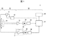
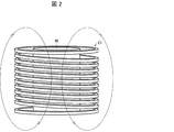
- FIG. 1 It is a circuit diagram of the nondestructive inspection apparatus which concerns on Embodiment 1 of this invention. It is a schematic diagram which shows the AC magnetism generated in the coil which concerns on Embodiment 1.
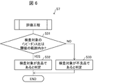
- FIG. It is a flowchart explaining the non-destructive inspection method of the steel material which concerns on Embodiment 1. It is a flowchart which shows the flow of the manufacturing process which concerns on Embodiment 1. It is a flowchart which shows the process flow of the setting process which concerns on Embodiment 1. It is a flowchart which shows the process flow of the evaluation process which concerns on Embodiment 1.
- (A) is a graph showing an example of the calculation result of the impedance ratio of the evaluation process according to the first embodiment
- (b) is a diagram showing an example of the display result of the display device in the notification process according to the first embodiment. is there. It is a figure which shows the state of the magnetic permeability change of the steel material after the surface treatment which concerns on Embodiment 1. It is a graph which shows an example of the calculation result of the impedance ratio which concerns on the modification 1 of Embodiment 1. It is a flowchart which shows the process flow of the evaluation process which concerns on Embodiment 2 of this invention.
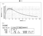
- (A) is a graph showing an example of the calculation result of the impedance ratio of the evaluation process according to the second embodiment
- (b) is a diagram showing an example of the display result of the display device in the notification process according to the second embodiment. is there.
- (A) is a graph showing an example of the calculation result of the impedance ratio of the evaluation process according to the third embodiment
- (b) is a diagram showing an example of the display result of the display device in the notification process according to the third embodiment. is there.
- the non-destructive inspection device 1 of the first embodiment includes an oscillator 10, a detector 20, and a measuring instrument 30.
- the oscillator 10 has an AC power supply 11 and a frequency variable circuit 12.
- the frequency variable circuit 12 is connected to the AC power supply 11 and changes the frequency of the AC current output from the AC power supply 11.
- the detector 20 has a coil 21 described later.
- One end side of the coil 21 (point A in FIG. 1) is connected to the AC power supply 11, and the AC current output from the AC power supply 11 is supplied.
- the other end side of the coil 21 (point B in FIG. 1) is connected to an I / V conversion circuit 34 described later.
- This detector 20 is used when evaluating the inspection target M, which will be described later (in this embodiment, a quality determination) (see FIG. 3).
- the circuit symbol in the broken line showing the coil 21 in FIG. 1 indicates the electrical equivalent circuit of the coil 21.
- the coil 21 is formed in a cylindrical shape by winding a plurality of conductive wires.
- the resonance frequency of the coil 21 can be increased by using a wire rod formed by bundling a plurality of thin conductive wires to form a single wire.
- a coil in which a wire rod is wound around a hollow cylindrical core may be used.
- a wire obtained by knitting and twisting several hundred enamel copper wires is wound around a resin cylinder, and then the wound wire is bonded with an epoxy resin to form a cylinder. I made it by removing it.
- the manufacturing method thereof is not particularly limited.
- the measuring instrument 30 includes an amplifier circuit 31, an absolute value circuit 32, a low-pass filter (LPF) 33, an I / V conversion circuit 34, an absolute value circuit 35, an LPF 36, a control unit 37, and a display device 38.
- the measuring instrument 30 measures a change in the impedance value of the coil 21 based on a signal indicating the electrical characteristics of the alternating current flowing through the coil 21.
- One end side (left side in FIG. 1) of the amplifier circuit 31 is connected to both ends (point A and point B in FIG. 1) of the coil 21, and the other end side (right side in FIG. 1) is connected to the absolute value circuit 32. It is connected. A signal of a potential difference between both ends of the coil 21 is input to the amplifier circuit 31. The signal input to the amplifier circuit 31 is amplified and input to the absolute value circuit 32.
- the absolute value circuit 32 is a full-wave rectifier circuit.
- the potential difference signal input to the absolute value circuit 32 is full-wave rectified and then converted to direct current by the LPF 33.
- the potential difference signal converted by the LPF 33 is input to the control unit 37.
- the I / V conversion circuit 34 is connected to the other end side of the coil 21 (point B in FIG. 1).
- the signal indicating the current value of the current flowing through the coil 21 is input to the I / V conversion circuit 34 and converted into a signal indicating the potential difference. Then, after being full-wave rectified by the absolute value circuit 35, it is converted into direct current by the LPF 36.
- the signal converted by the LPF 36 is input to the control unit 37.
- control unit 37 has a microprocessor, an interface circuit, a memory, a program for operating these, and the like.
- the control unit 37 is connected to the frequency variable circuit 12, the LPF 33, and the LPF 36.
- a signal indicating the electrical characteristics of the coil 21, that is, a signal of the frequency of the alternating current flowing through the coil 21, a signal of the current value for each frequency, and a signal of the potential difference are input to the control unit 37.
- the control unit 37 calculates the impedance value at each frequency based on the signal indicating the electrical characteristics of the coil 21.
- control unit 37 has a function of outputting a signal for automatically and continuously changing the frequency to the frequency variable circuit 12. Further, in the first embodiment, in a state where the steel material to be inspected M is arranged inside the coil 21, the frequency is changed via the frequency variable circuit 12 by the control output from the control unit 37 (see FIG. 2). The frequency of the alternating current may be changed manually.
- control unit 37 calculates an impedance value Z 2 for each frequency to be continuously changed, and the calculated impedance value Z 2 and the impedance value Z 0 of the steel material (reference material) before the predetermined surface treatment. Calculate the impedance ratio ⁇ 2 (Z 2 / Z 0 ) with. Further, the control unit 37 calculates an impedance ratio ⁇ 1 (Z 1 / Z 0 ) between the impedance value Z 1 for each penetration depth in the case of a non-defective product and the impedance Z 0 of the steel material before surface treatment. Then, the impedance ratio gamma 2 of the test object M, by comparing the impedance ratio gamma 1 non-defective, also functions for performing quality determination of the surface condition of the test object M.
- the display device 38 is a device that displays an evaluation result (good / bad determination result) by the control unit 37 in the notification step (S8) described later, as shown in FIG. 7B.
- the display device 38 displays a graph showing the relationship between the impedance ratio ⁇ 2 of the inspection target M and the penetration depth as shown in FIG. 7A. ..
- the control unit 37 can continuously change the frequency of the alternating current from a low frequency to a high frequency by outputting a control signal to the frequency variable circuit 12. Then, by continuously changing the frequency of the alternating current by the frequency variable circuit 12, it is possible to continuously change the penetration depth of the alternating current magnetism into the inspection target M. Specifically, the frequency of the alternating current is continuously changed from, for example, a low frequency of about 10 kHz to a high frequency of about 20 MHz. As a result, the penetration depth of the AC magnetism into the inspection target M is changed from 0 ⁇ m to 150 ⁇ m.
- the penetration depth of the AC magnetism into the inspection target M is specified from the frequency of the AC current by using the relational expression of the equation (1).
- ⁇ is the penetration depth [m]
- f is the AC frequency [Hz]
- ⁇ is the conductivity [S / m] of the inspection target M
- ⁇ is the magnetic permeability [H / m] of the inspection target M. ] Is represented.
- the control unit 37 continuously changes the penetration depth of the AC magnetism into the inspection target M, and obtains the ratio between the potential difference between both ends of the coil 21 and the current value flowing through the coil 21. Calculate the impedance value for each penetration depth. This impedance value becomes a different value due to a change in magnetic permeability of the steel material after surface treatment.
- the magnetic permeability of the inspection target M is the carbon content and nitrogen content of the inspection target M, the magnitude and direction of elastic strain, the magnitude of plastic strain, the arrangement state (phase transformation) of atoms, the size and shape, and the hardness. It changes depending on various parameters such as.
- various evaluations are performed on the steel material after surface treatment as the inspection target M by utilizing the relationship between the above parameters and the magnetic permeability. Do (see Figure 3).
- a casting process (S11) is performed, and then a machining process (S12) such as cutting is performed.
- a machining process such as cutting is performed.
- a steel material is cut into a desired shape (cylindrical shape, gear shape, etc.). The type of machining can be changed as appropriate.
- the carburizing and quenching step (S13) is performed.
- the carburizing and quenching treatment is performed on the steel material, so that the amount of carbon on the surface of the steel material increases and the magnetic permeability of the steel material decreases.
- the carbon content is only an example of a factor for changing the magnetic permeability, and the magnetic permeability of the inspection target M changes depending on the plurality of parameters described above.
- the shot peening step (S14) is performed.
- a shot peening device (not shown) is used to project a small spherical projection material onto the surface of the steel material to modify the surface of the steel material. After this shot peening, the magnetic permeability of the surface of the steel material increases.
- finishing process (S15) is performed.
- the steel material is appropriately subjected to finishing treatments such as brush polishing, buffing, and barrel polishing.
- Non-destructive inspection method Next, a non-destructive inspection method for steel materials by the non-destructive inspection apparatus 1 of the first embodiment will be described with reference to the flowchart shown in FIG.
- the flowchart shown in FIG. 3 is an example, and the order of the flowcharts is not limited.
- the steel material of the inspection target M is prepared, and the preparatory step (S1) for preparing the non-destructive inspection device 1 described above is performed.
- the steel material of the inspection target M for example, steel materials used for components (gears, gears, etc.) of automobiles, aircraft, construction machinery, etc., and other springs, dies, tools, etc. are assumed.
- the steel material subjected to the carburizing and quenching treatment in the carburizing and quenching step (S13) and then the shot peening treatment in the shot peening step (S14) is set as the inspection target M.
- the material of the steel material of the inspection target M for example, chromium molybdenum steel (JIS standard: SCM420) shall be used.
- the shape of the steel material to be inspected M the one machined into a cylindrical shape in the machining step (S12) is used.
- the preparation step (S1) the preparation step (S1)
- the setting step (S2) is performed.
- each process is performed in the order of the flowchart shown in FIG.
- the flowchart shown in FIG. 5 is an example and is not limited thereto.
- a steel material (reference material) before surface treatment is placed at a predetermined position of the non-destructive inspection device 1 (S21).
- the reference material is arranged at the center of the circular cross section inside the cylindrical coil 21, so that the AC magnetism excited by the coil 21 can permeate the inside of the steel material before the surface treatment.
- various measurement conditions such as the arrangement position of the reference material and the frequency range of the AC magnetism flowing through the coil 21 are set (S22).
- measurement conditions that can appropriately evaluate the surface treatment state of the inspection target M are set.
- the frequency of the AC current is continuously changed by the frequency variable circuit 12, and the penetration depth of the AC magnetism in the reference material is continuously changed.
- the impedance value Z 0 for each penetration depth of the reference material is measured (S23), and the measured impedance value Z 0 for each penetration depth of the reference material is stored in a database (not shown) (S24).
- the impedance value of the reference material subjected to various surface treatments such as shot peening treatment, quenching treatment, nitriding treatment, carburizing treatment, tempering treatment, annealing treatment, surface treatment treatment, polishing treatment, and tempering treatment in the database.
- the data regarding Z 0 may be stored in advance.
- the determination method used in the evaluation step (S7) described later is selected (S25). There are three determination methods, which will be described later: (1) area determination, (2) peak determination, and (3) area determination. From these three determination methods, one of the determination methods is selected.
- At least one or more steel materials (good products) that have been well surface-treated are subjected to the same treatment as in S21 to S24.
- the impedance value Z 1 of the non-defective product is measured, and the data related to this impedance value Z 1 is stored in the database.
- the impedance ratio ⁇ 1 (Z 1 / Z 0 ) between the impedance value Z 0 for each penetration depth of the reference material and the impedance value Z 1 for each penetration depth of the non-defective product is calculated, and this impedance ratio ⁇ 1 is calculated. Store in the database.
- the threshold range used in the determination method selected in S25 is set (S26).
- the type of determination method and the range of the threshold value it is possible to adjust the accuracy of evaluation of the surface treatment state of the inspection target M.
- the setting step (S2) is completed.
- the arrangement step (S3) for arranging the steel material of the inspection target M is performed.
- the steel material of the inspection target M is arranged at the center of the circular cross section inside the cylindrical coil 21, so that the AC magnetism excited by the coil 21 can penetrate into the inside of the inspection target M.
- the arrangement method is not limited to this, as long as the AC magnetism of the coil 21 permeates the inside of the inspection target M, and the inspection target M may be arranged at a position facing the coil 21. ..
- an eddy current generation step (S4) for generating an eddy current in the inspection target M is performed.
- the control unit 37 operates the AC power supply 11 via the frequency variable circuit 12.
- AC power supply 11 When the AC power supply 11 is activated, AC magnetism is excited in the coil 21 (see FIG. 2).
- an eddy current is generated inside the inspection target M.
- a frequency changing step (S5) is performed in which the penetration depth of the AC magnetism into the inspection target M is continuously changed.
- the control unit 37 continuously changes the frequency of the AC current output from the AC power supply 11 by outputting the control signal to the frequency variable circuit 12.
- the penetration depth of the AC magnetism into the inspection target M continuously changes.
- the penetration depth of the AC magnetism into the inspection target M varies depending on the internal composition of the inspection target M even if the same AC magnetism is applied to the inspection target M.
- the penetration depth of the AC magnetism into the inspection target M was changed from 0 ⁇ m to 150 ⁇ m, and the quality of the surface condition of the inspection target M was inspected (FIGS. 7A and 7). 8).
- an impedance calculation step (S6) for calculating the impedance value Z 2 for each penetration depth of the inspection target M is performed. Specifically, the control unit 37 calculates the impedance value Z 2 based on the potential difference between both ends of the coil 21 (points A and B in FIG. 1) and the current value flowing through the coil 21.
- an evaluation step (S7) is carried out to inspect the surface condition of the inspection target M. Specifically, each process proceeds in the order of the flowchart shown in FIG.
- the flowchart shown in FIG. 6 is an example, and the present invention is not limited to this.
- the area determination is used among the above three determination methods.
- the control unit 37 has an impedance value Z 2 for each penetration depth of the inspection target M calculated in the impedance calculation step (S6), and a steel material (reference material) before surface treatment measured in the setting step (S2). ) Is calculated as the impedance ratio ⁇ 2 (Z 2 / Z 0 ) with the impedance value Z 0 for each penetration depth. Then, it is determined whether or not the calculated impedance ratio ⁇ 2 of the inspection target M is within the threshold range (S31).
- the threshold range the data set in the setting step (S2) is used.
- the control unit 37 determines that the inspection target M is a non-defective product (S32). On the other hand, when the impedance ratio ⁇ 2 of the inspection target M is not within the threshold range (S31: No), the control unit 37 determines that the inspection target M is a defective product (S33).
- a notification step (S8) for notifying whether the inspection target M is a non-defective product or a defective product is performed.
- the display device 38 displays whether or not the inspection target M is a non-defective product.
- the notification step (S8) as shown in FIGS. 7A and 8A, a graph in which the penetration depth is plotted on the horizontal axis and the impedance ratio ⁇ 2 of the inspection target M is plotted on the vertical axis is displayed. It is displayed on the device 38. Further, as shown in FIG. 7B, the display device 38 displays the determination result of the non-defective product determination.
- the number of measured Ms to be inspected is 7, and 6 of these 7 are judged to be non-defective and 1 is determined to be defective. There is.
- the number of set points indicates that the impedance ratio ⁇ 2 was calculated at a total of 151 points where the penetration depth was between 0 ⁇ m and 150 ⁇ m.
- FIG. 8 is a diagram showing a state of change in magnetic permeability of the steel material after surface treatment.
- the carburizing and quenching step (S13) when the carburizing and quenching treatment is performed, the carbon content on the surface of the steel material increases. As the carbon content of the steel increases, the magnetic permeability decreases. Due to the influence of such carburizing, the impedance ratio ⁇ 2 of the inspection target M becomes smaller (see the circle in FIG. 8) after the carburizing and quenching treatment, as shown in FIG.
- the magnetic permeability of the steel material increases due to the surface modification of the steel material. Due to the influence of such shot peening (SP), the impedance ratio ⁇ 2 of the inspection target M becomes large after the shot peening process (see the square mark in FIG. 8).
- the magnetic permeability of the inspection target M when it is determined that the magnetic permeability of the inspection target M is higher than that of the non-defective product, it is specified that the carbon content of the inspection target M is low and a problem has occurred in the carburizing and quenching step (S13).
- the magnetic permeability of the inspection target M when it is determined that the magnetic permeability of the inspection target M is smaller than that of the non-defective product, it is specified that a problem has occurred in the shot peening step (S14) and the magnetic permeability cannot be sufficiently increased.
- the penetration depth of the AC magnetism into the inspection target M is continuously increased.
- a value Z 2 of the impedance of the impedance calculation step (S6) for each penetration depth of the test object M calculated by the impedance of each penetration depth in the surface pre-treatment of the steel (base material)
- the impedance ratio ⁇ 2 which is the ratio of the value to Z 0 , can be calculated.
- the change factor of the magnetic permeability of the inspection target M can be specified, and the surface treatment state of the inspection target M can be evaluated with high accuracy.
- the impedance ratio ⁇ 1 of the non-defective product and the impedance ratio ⁇ 2 of the defective product it is possible to evaluate the surface treatment state (good / bad judgment) of the inspection target M with high accuracy. Further, by paying attention to the carbon content state, which is one of the factors for changing the magnetic permeability of the inspection target M, it is possible to identify in which of the carburizing process (S13) and the shot peening step (S14) the defect occurred. Is.
- the determination methods to be executed in the evaluation step (S7) are (1) area determination, (2) peak determination, and (3). ) Since the optimum method can be selected from the three area determinations for evaluation, the accuracy of evaluation of the surface treatment state can be improved. When it is assumed that the penetration depth of the inspection target M occurs over a wide range as in the first embodiment (see (a) of FIG. 7), the area determination can be used to perform a good evaluation.
- the setting step (S2) by appropriately setting the threshold range used in the evaluation step (S7), the accuracy of the evaluation of the surface treatment state can be adjusted according to the needs of the user.
- the optimum method is selected from the above-mentioned three determination methods (1) to (3) according to the inspection target M and evaluated. It can be done and the accuracy of evaluation can be improved. For example, when it is assumed that the difference between the impedance ratio ⁇ 1 of the non-defective product and the impedance ratio ⁇ 2 of the defective product occurs over the entire penetration depth of the inspection target M, the distribution of the ratio of (1) By performing the evaluation (area determination) using the above, it is possible to reliably evaluate the surface treatment state.
- FIG. 9 is a graph showing an example of the calculation result of the impedance ratio ⁇ 2 according to the modified example 1.
- the impedance ratio ⁇ 2 of the inspection target M calculated in the evaluation step (S7) differs depending on the difference in the particle size of the projection material used in the shot peening step (S14). It turns out that Specifically, when the size of the particle size of the projection material is increased, the magnetic permeability of the inspection target M is increased, and the impedance ratio ⁇ 2 of the inspection target M is increased over a wide range of the penetration depth. On the other hand, when the size of the particle size of the projection material is reduced, the magnetic permeability of the inspection target M is reduced, and the impedance ratio ⁇ 2 of the inspection target M is reduced over a wide range of the penetration depth.
- At least one or more steel materials (non-defective products) having a desired size and shape are subjected to the same treatment as in S21 to S24.
- the impedance value Z 1 of the non-defective product is measured, and the data related to this impedance value Z 1 is stored in the database.
- the impedance ratio ⁇ 1 (Z 1 / Z 0 ) between the impedance value Z 0 for each penetration depth of the reference material and the impedance value Z 1 for each penetration depth of the non-defective product is calculated, and this impedance ratio ⁇ 1 is calculated.
- the threshold range used in the determination method selected in S25 is set (S26).
- the size and shape of the inspection target M can be evaluated in the evaluation step S7. Thereby, when the size and shape of the inspection target M do not satisfy the desired conditions, it can be determined that the inspection target M is a defective product.
- the steel material (reference material) before the surface treatment is arranged in the setting step (S2) shown in FIG. 5 (S21).
- the measurement conditions are set (S22), the impedance value Z 0 of the reference material is measured (S23), and the impedance value Z 0 of the reference material is stored (S24).
- one determination method is selected from the three determination methods of (1) area determination, (2) peak determination, and (3) area determination (S25).
- At least one or more steel materials (non-defective products) having a desired hardness are subjected to the same treatment as in S21 to S24.
- the impedance value Z 1 of the non-defective product is measured, and the data related to this impedance value Z 1 is stored in the database.
- the impedance ratio ⁇ 1 (Z 1 / Z 0 ) between the impedance value Z 0 for each penetration depth of the reference material and the impedance value Z 1 for each penetration depth of the non-defective product is calculated, and this impedance ratio ⁇ 1 is calculated.
- the threshold range used in the determination method selected in S25 is set (S26).
- the hardness of the inspection target M can be evaluated in the evaluation step (S7). Thereby, when the hardness of the inspection target M does not satisfy the desired condition, it can be determined that the inspection target M is a defective product.
- the control unit 37 determines whether or not the value of the impedance ratio ⁇ 2 of the inspection target M at a specific penetration depth is within the threshold value. (S41). Specifically, the evaluation of the inspection target M (Embodiment 2) is limited to the portion of the penetration depth where the value of the impedance ratio ⁇ 2 of the inspection target M peaks (see the box line in FIG. 11A). Then, pass / fail judgment) is performed.
- the control unit 37 determines that the inspection target M is a non-defective product (S42). On the other hand, when the impedance ratio ⁇ 2 of the inspection target M is not within the threshold range (S41: No), the control unit 37 determines that the inspection target M is a defective product (S43).
- the determination result of the non-defective product determination is displayed on the display device 38.
- the number of measurements of the inspection target M is 7, and a case where it is determined that 6 of these 7 are non-defective and 1 is defective is displayed. ing. Further, in the peak determination, it is displayed that the evaluation was performed by limiting the penetration depth to the range of 10 ⁇ m to 30 ⁇ m.
- the non-destructive inspection method for the steel material of the second embodiment described above can also evaluate the surface treatment state of the inspection target M with high accuracy.
- the difference between the impedance ratio ⁇ 1 of the non-defective product and the impedance ratio ⁇ 2 of the defective product becomes the peak of the impedance ratio ⁇ 2.
- the evaluation can be performed with higher accuracy when it is expected to appear prominently at (specific penetration depth).
- FIGS. 12 and 13 (a) and 13 (b) members having the same functions as those described in the first embodiment are designated by the same reference numerals, and the description thereof will be omitted as appropriate.
- area determination is used in the evaluation process.
- the surface treatment state of the inspection target M is evaluated (good / bad judgment).
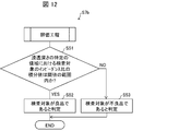
- the control unit 37 determines whether or not the integrated value of the impedance ratio ⁇ 2 of the inspection target M in a specific value range of the penetration depth (see the black fill in FIG. 13A) is within the threshold range (S51). ).
- the control unit 37 determines that the inspection target M is a good product (S52). ).
- the control unit 37 determines that the inspection target M is a defective product. (S53).
- the determination result of the non-defective product determination is displayed on the display device 38.
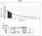
- the display example shown in FIG. 13B it is displayed that the integrated value in the range of 10 ⁇ m to 30 ⁇ m in the penetration depth was calculated and evaluated in the area determination.
- the non-destructive inspection method for the steel material of the third embodiment described above can also evaluate the surface treatment state of the inspection target M with high accuracy.
- the evaluation step (S7b) by performing the evaluation step (S7b) using the area determination, when it is difficult to evaluate using either of the above-mentioned area determination and peak determination determination methods, the penetration depth can be specified.
- the evaluation using the integrated value of the impedance ratio ⁇ 2 in the range it is possible to discriminate a minute difference between the impedance ratio ⁇ 1 of the non-defective product and the impedance ratio ⁇ 2 of the defective product.
- the determination method used in the evaluation step (S7) is the optimum method from the three determination methods of (1) area determination, (2) peak determination, and (3) area determination. Was selected for evaluation, but the evaluation is not limited to this.
- two determination methods may be used from the three determination methods (1) to (3) above, or all three determination methods may be used.
- the determination method may be appropriately changed according to the penetration depth to perform the evaluation.
- the steel material after the shot peening treatment is set as the inspection target M, but the present invention is not limited to this.
- the surface treatment for example, the steel material after being subjected to quenching treatment, nitriding treatment, carburizing treatment, tempering treatment, annealing treatment, surface treatment treatment, polishing treatment, tempering treatment can be set as the inspection target M. ..
- the impedance value Z 0 of the reference material stores the impedance ratio gamma 1 of the impedance value Z 1 of the good in the database, properly setting the range of the threshold value used for evaluation Therefore, it is possible to evaluate the surface treatment state of the inspection target M with high accuracy.
- the surface treatment state of the inspection target M the arrangement state (phase transformation) of the atoms of the inspection target M, the magnitude of the plastic strain of the inspection target M, and the magnitude and orientation of the elastic strain of the inspection target M are evaluated. You can also do it.
- the steel material subjected to the carburizing and quenching treatment in the carburizing and quenching step (S13) contains retained austenite, and when this is subjected to a shot peening treatment, it undergoes phase transformation to martensite and the content of retained austenite decreases. As the martensite content increases, the magnetic permeability of the steel increases. Utilizing this relationship, it is possible to evaluate the phase transformation of the inspection target M as the surface treatment state of the inspection target M.
- the magnetic permeability of the steel material changes as the magnitude of the plastic strain changes. Using this relationship, it is also possible to evaluate the magnitude of the plastic strain of the inspection target M.
- the magnetic permeability of the steel material changes as the magnitude and direction of the elastic strain change. Using this relationship, it is also possible to evaluate the magnitude and orientation of the elastic strain of the inspection target M.
- the magnitude relationship of the above-mentioned factors for changing the magnetic permeability is "phase transformation of inspection target M> plastic strain of inspection target M> magnitude and direction of elastic strain of inspection target M".
- the non-destructive inspection method for steel materials includes a preparation step, an arrangement step, an eddy current generation step, a frequency changing step, an impedance calculation step, and an evaluation step.
- a non-destructive inspection device having a frequency variable circuit and a coil is prepared.
- the frequency variable circuit can change the frequency of the alternating current.
- the coil can excite alternating magnetism with an alternating current.
- the inspection target is placed so that the AC magnetism excited by the coil permeates the inside of the inspection target.
- the inspection target is steel after surface treatment.
- the eddy current is generated in the inspection target by infiltrating the AC magnetism into the inspection target.
- the frequency of the alternating current is continuously changed from the low frequency to the high frequency by the frequency variable circuit, so that the penetration depth of the alternating current magnetism into the inspection target is continuously changed.
- the impedance value for each penetration depth of the inspection target is calculated based on the potential difference between both ends of the coil and the current value flowing through the coil.
- the ratio between the impedance value for each penetration depth of the inspection target calculated in the impedance calculation step and the impedance value for each penetration depth in the steel material before surface treatment is calculated, and the ratio is calculated.
- the change factor of the magnetic permeability of the inspection target is specified and the surface treatment state is evaluated.
- Factors that change the magnetic permeability include, for example, the carbon content and nitrogen content of the inspection target, the size and shape of the inspection target, the hardness of the inspection target, and the like.
- impedance is obtained by continuously changing the penetration depth of AC magnetism into the inspection target after generating an eddy current in the inspection target by the non-destructive inspection device.
- the ratio (impedance ratio) between the impedance value for each penetration depth of the inspection target calculated in the calculation step and the impedance value for each penetration depth in the steel material before surface treatment can be calculated. Then, based on the calculation result of this ratio, it is possible to identify the change factor of the magnetic permeability of the inspection target and evaluate the surface treatment state of the inspection target with high accuracy.
- the carbon content of the inspection target is low and the carburizing and quenching process is performed. Identify that the problem has occurred.
- the magnetic permeability of the inspection target is smaller than that of the non-defective product, it is specified that a problem occurs in the shot peening process and the magnetic permeability cannot be sufficiently increased. In this way, the surface treatment state of the inspection target can be evaluated with high accuracy.
- the factors for changing the magnetic permeability include the carbon content of the inspection target, the magnitude and direction of the elastic strain of the inspection target, and the inspection target. It is characterized in that it includes either the magnitude of the plastic strain and the arrangement state of the atoms to be inspected.
- the non-destructive inspection method for steel materials as a factor of the change in magnetic permeability, for example, by evaluating the carbon content state (carbon content) of the inspection target, it is caused by the carbon content state of the good product and the defective product.
- the carbon content of the inspection target may be evaluated by calculating the carbon content of the inspection target based on the above ratio. Further, the carbon content state of the inspection target may be evaluated based on the correlation between the ratio and the carbon content state of the inspection target.
- the surface treatment includes shot peening treatment, quenching treatment, nitriding treatment, carburizing treatment, tempering treatment, annealing treatment, surface treatment treatment, polishing treatment, and tempering treatment.
- the process is characterized by at least inclusion.
- the evaluation step (1) determination of whether or not the distribution of the ratio is within the threshold value, and (2) the value of the ratio at a specific penetration depth. At least one of the determination methods of determining whether or not is within the threshold value and (3) determining whether or not the integral value of the ratio value in the specific range of the penetration depth is within the threshold value is executed. This is characterized by evaluating the surface treatment state of the inspection target.
- the optimum method can be selected from the above-mentioned three determination methods (1) to (3) according to the inspection target and evaluated.
- the accuracy of evaluation can be improved. For example, if it is assumed that the difference in impedance ratio between the non-defective product and the defective product will occur over a wide range of the penetration depth of the inspection target M, the evaluation using the ratio distribution of (1) can be performed. preferable. In addition, when it is assumed that the difference in impedance ratio between the non-defective product and the defective product appears remarkably at a specific location of the penetration depth, the evaluation using the ratio at the specific penetration depth in (2) is performed. It is preferable to do so. If evaluation is difficult using either of the above (1) and (2) determination methods the evaluation is performed using the integral value of the ratio value in the specific range of the penetration depth. The difference in ratio can be determined.
- the determination method to be executed in the evaluation step is selected before the arrangement step, and the threshold range of the selected determination method is set. It is characterized by performing a setting process.
- the accuracy of evaluation can be adjusted according to the needs of the user by appropriately setting the threshold range used in the evaluation process in the setting process.
- the non-destructive inspection method for a steel material according to one aspect of the present invention is characterized in that, in the evaluation step, the size and shape of the inspection target are evaluated as the evaluation of the surface treatment state.
- the non-destructive inspection method for a steel material according to one aspect of the present invention is characterized in that the hardness of the inspection target is evaluated as the evaluation of the surface treatment state in the evaluation step.
- Non-destructive inspection device 11 AC power supply 12 Frequency variable circuit 21 Coil 37 Control unit 38 Display device M Inspection target S1 Preparation process S2 Setting process S3 Arrangement process S4 Eddy current generation process S5 Frequency change process S6 Impedance calculation process S7, S7a, S7b Evaluation process S8 Notification process
Landscapes
- Chemical & Material Sciences (AREA)
- Chemical Kinetics & Catalysis (AREA)
- Electrochemistry (AREA)
- Physics & Mathematics (AREA)
- Health & Medical Sciences (AREA)
- Life Sciences & Earth Sciences (AREA)
- Analytical Chemistry (AREA)
- Biochemistry (AREA)
- General Health & Medical Sciences (AREA)
- General Physics & Mathematics (AREA)
- Immunology (AREA)
- Pathology (AREA)
- Investigating Or Analyzing Materials By The Use Of Magnetic Means (AREA)
Abstract
検査対象の透磁率変化の要因を特定して、検査対象の表面処理状態を高精度で評価する。本発明の一態様に係る鋼材の非破壊検査方法は、準備工程(S1)、配置工程(S3)、渦電流生成工程(S4)、周波数変更工程(S5)、インピーダンス算出工程(S6)、評価工程(S7)と、を有する。準備工程(S1)では、非破壊検査装置を準備する。配置工程(S3)では、検査対象を配置する。渦電流生成工程(S4)では、検査対象に渦電流を発生させる。周波数変更工程(S5)では、検査対象への前記交流磁気の浸透深さを連続的に変化させる。インピーダンス算出工程(S6)では、検査対象の浸透深さ毎のインピーダンスの値を算出する。評価工程(S7)では、検査対象の浸透深さ毎のインピーダンスの値と、表面処理前の鋼材における浸透深さ毎のインピーダンスの値との比率を算出し、比率の算出結果に基づいて、検査対象の透磁率の変化要因を特定して表面処理状態の評価を行う。
Description
本発明は、鋼材の非破壊検査方法に関する。
従来、鋼材の製造工程においては、ショットピーニングや熱処理等の表面処理が施された後の鋼材を検査対象とし、当該検査対象を破壊することなく、上記表面処理が正常に行われたか否かを測定する様々な非破壊検査方法が提案されている。
例えば、検査対象の鋼材の表面上に配置したコイルに交流電流を流して、当該コイルのインピーダンスを測定することで、ショットピーニング処理後の検査対象の残留応力分布を測定する非破壊検査方法がある(特許文献1参照)。この非破壊検査方法では、残留応力の発生状態が異なる複数のサンプル(ショットピーニング処理後の鋼材)のインピーダンスに関するデータを予め取得して、検査対象のインピーダンスに関するデータと比較することによって、検査対象の評価を行っている。
しかしながら、上述した非破壊検査方法では、ショットピーニング処理後の鋼材の残留応力の発生状態を測定できるものの、例えば、ショットピーニング処理後の鋼材の炭素含有量が正常か否かを判定することはできない。このため、例えば、浸炭焼入れ工程を行った後に、ショットピーニング工程が行われた場合、浸炭焼入れ工程において不具合が生じたのか、ショットピーニング工程において不具合が生じたのか判別できない。このように、上述した非破壊検査方法では、検査対象の鋼材が不良品と判定されたとしても、どの処理工程において不具合が生じたのか特定できないという問題があり、検査対象の表面状態の評価の精度に改善の余地がある。
本発明の一態様は、上述した課題に鑑みてなされたものであり、検査対象の表面状態の評価を高い精度で行うことができる鋼材の非破壊検査方法を提供することを目的とする。
上記の課題を解決するためになされた本発明の一態様に係る鋼材の非破壊検査方法は、準備工程と、配置工程と、渦電流生成工程と、周波数変更工程と、インピーダンス算出工程と、評価工程と、を有する。
準備工程では、周波数可変回路とコイルとを有する非破壊検査装置を準備する。前記周波数可変回路は、交流電流の周波数を変更可能である。前記コイルは、交流電流により交流磁気を励起可能である。
配置工程では、前記コイルにより励起された交流磁気が検査対象の内部に浸透するように該検査対象を配置する。検査対象は表面処理後の鋼材とする。
渦電流生成工程では、前記交流磁気を検査対象の内部に浸透させることにより、検査対象に渦電流を発生させる。
周波数変更工程では、前記周波数可変回路によって交流電流の周波数を低周波数から高周波数まで連続的に変更することにより、検査対象への交流磁気の浸透深さを連続的に変化させる。
インピーダンス算出工程では、前記コイル両端の間の電位差及びコイルを流れる電流値に基づいて、検査対象の浸透深さ毎のインピーダンスの値を算出する。
そして、評価工程では、インピーダンス算出工程にて算出された検査対象の浸透深さ毎のインピーダンスの値と、表面処理前の鋼材における浸透深さ毎のインピーダンスの値との比率を算出し、前記比率の算出結果に基づいて、検査対象の透磁率の変化要因を特定して表面処理状態の評価を行う。透磁率の変化要因には、例えば、検査対象の炭素含有量や窒素含有量、検査対象のサイズや形状、検査対象の硬さ等が含まれるものとする。
本発明の鋼材の非破壊検査方法によれば、検査対象の透磁率変化の要因を特定して、検査対象の表面処理状態を高精度で評価することができる。
〔実施形態1〕
以下、本発明の実施形態1に係る非破壊検査方法について、図1~図9を参照して説明する。
以下、本発明の実施形態1に係る非破壊検査方法について、図1~図9を参照して説明する。
[非破壊検査装置]
実施形態1の非破壊検査装置1は、図1に示すように、発振器10、検出器20、及び計測器30を備えている。発振器10は、交流電源11、及び周波数可変回路12を有している。周波数可変回路12は、交流電源11に接続されており、交流電源11から出力される交流電流の周波数を変更する。
実施形態1の非破壊検査装置1は、図1に示すように、発振器10、検出器20、及び計測器30を備えている。発振器10は、交流電源11、及び周波数可変回路12を有している。周波数可変回路12は、交流電源11に接続されており、交流電源11から出力される交流電流の周波数を変更する。
検出器20は、後述するコイル21を有している。コイル21の一端側(図1の点A)は、交流電源11に接続されており、交流電源11から出力された交流電流が供給される。コイル21の他端側(図1の点B)は、後述するI/V変換回路34に接続されている。この検出器20は、後述する検査対象Mの評価(本実施形態では、良否判定)を行う際に用いられる(図3参照)。なお、図1のコイル21を示す破線内の回路記号は、コイル21の電気等価回路を示している。
コイル21は、図2に示すように、複数本の導通性のある線材を巻回して円筒状に形成されたものである。実施形態1では、複数本の細い導線を束ねて一本の線のように形成したものを線材として用いることで、コイル21の共振周波数を高くすることができる。なお、コイル21として、中空の円筒形状のコアに線材を巻回したもの(有芯コイル)を用いてもよい。また、線材は、単一の導線を用いてもよい。
実施形態1のコイル21の製作方法は、まず、数百本のエナメル銅線を編み込みツイストした線材を、樹脂製の円筒に巻回した後、巻回した線材をエポキシ樹脂で接着し、円筒を取り外すことで製作した。
なお、コイル21の製作方法としては、他にも、例えば熱硬化性樹脂で被覆した線材を用いてこの線材を巻回した後、熱風や乾燥炉等で加熱して線材をコイル状の形状を保つように固定する方法がある。このように、線材がコイル状の形状を保つことができれば、その製作方法は特に限定されない。
計測器30は、増幅回路31、絶対値回路32、ローパスフィルタ(LPF)33、I/V変換回路34、絶対値回路35、LPF36、制御部37、及び表示装置38を備えている。計測器30は、コイル21を流れる交流電流の電気特性を示す信号に基づいて、コイル21のインピーダンスの値の変化を計測するものである。
増幅回路31は、一端側(図1では左側)がコイル21の両端(図1の点A及び点B)に接続されていると共に、他端側(図1では右側)が絶対値回路32に接続されている。この増幅回路31には、コイル21の両端間の電位差の信号が入力される。増幅回路31に入力された信号は増幅され、絶対値回路32に入力される。
絶対値回路32は、全波整流回路のことである。絶対値回路32に入力された電位差信号は、全波整流された後、LPF33により直流に変換される。LPF33で変換された電位差信号は、制御部37に入力される。
I/V変換回路34は、コイル21の他端側(図1の点B)に接続されている。コイル21を流れた電流の電流値を示す信号は、I/V変換回路34に入力され、電位差を示す信号に変換される。そして、絶対値回路35により全波整流された後、LPF36により直流に変換される。LPF36で変換された信号は、制御部37に入力される。
制御部37は、図示しないが、マイクロプロセッサ、インターフェイス回路、メモリ、及び、これらを作動させるプログラム等を有している。制御部37は、周波数可変回路12、LPF33、及びLPF36に接続されている。制御部37には、コイル21の電気特性を示す信号、すなわち、コイル21を流れる交流電流の周波数の信号、各周波数に対する電流値の信号及び電位差の信号が入力される。制御部37は、コイル21の電気特性を示す信号に基づいて、各周波数におけるインピーダンスの値を演算する。
また、制御部37は、周波数可変回路12に自動で連続的に周波数を変更する信号を出力する機能を有している。また、実施形態1では、検査対象Mである鋼材をコイル21の内部に配置した状態で、制御部37からの制御出力により周波数可変回路12を介して周波数を変更する(図2参照)。なお、交流電流の周波数の変更を手動で行ってもよいものとする。
また、制御部37は、連続的に変更する周波数毎のインピーダンスの値Z2を算出し、算出したインピーダンスの値Z2と、所定の表面処理前の鋼材(基準材)のインピーダンスの値Z0とのインピーダンス比γ2(Z2/Z0)を算出する。また、制御部37は、良品の場合の浸透深さ毎のインピーダンスの値Z1と、表面処理前の鋼材のインピーダンスZ0とのインピーダンス比γ1(Z1/Z0)を算出する。そして、検査対象Mのインピーダンス比γ2と、良品のインピーダンス比γ1とを比較することにより、検査対象Mの表面状態の良否判定を行う機能も果たす。
表示装置38は、後述する報知工程(S8)において、図7の(b)に示すように、制御部37による評価結果(良否判定結果)を表示する装置である。表示装置38には、検査対象Mの良否判定の結果以外にも、図7の(a)に示すように、検査対象Mのインピーダンス比γ2と浸透深さとの関係を示すグラフが表示される。
[渦電流の制御方法]
次に、非破壊検査装置1における渦電流の制御方法について説明する。まず、非破壊検査装置1のコイル21に、交流電源11から交流電流を印加する。コイル21に交流電流が印加されると、後述するようにコイル21の内部に配置された検査対象Mに、コイル21により励起された交流磁気が浸透する(図2参照)。これにより、検査対象Mには渦電流が発生する。
次に、非破壊検査装置1における渦電流の制御方法について説明する。まず、非破壊検査装置1のコイル21に、交流電源11から交流電流を印加する。コイル21に交流電流が印加されると、後述するようにコイル21の内部に配置された検査対象Mに、コイル21により励起された交流磁気が浸透する(図2参照)。これにより、検査対象Mには渦電流が発生する。
実施形態1の非破壊検査装置1では、制御部37が、周波数可変回路12に制御信号を出力することにより、交流電流の周波数を低周波数から高周波数まで連続的に変更することができる。そして、周波数可変回路12によって交流電流の周波数を連続的に変更することで、検査対象Mへの交流磁気の浸透深さを連続的に変化させることが可能となっている。具体的には、交流電流の周波数を、例えば、10kHz程度の低周波数から、20MHz程度の高周波数まで連続的に変更させる。これにより、検査対象Mへの交流磁気の浸透深さを、0μm~150μmまで変化させる。
ここで、上記した検査対象Mへの交流磁気の浸透深さと、交流電流の周波数との間には、以下の式(1)に示される関係がある。実施形態1では、式(1)の関係式を利用して、交流電流の周波数から検査対象Mの交流磁気の浸透深さを特定する。

上記式(1)において、δは浸透深さ[m]、fは交流周波数[Hz]、σは検査対象Mの導電率[S/m]、μは検査対象Mの透磁率[H/m]を表している。
制御部37は、検査対象Mへの交流磁気の浸透深さを連続的に変化させ、コイル21の両端間の電位差と、コイル21を流れる電流値との比を求めることにより、検査対象Mの浸透深さ毎のインピーダンスの値を算出する。このインピーダンスの値は、表面処理後の鋼材における透磁率の変化等に起因して異なる値となる。
上記検査対象Mの透磁率は、検査対象Mの炭素含有量や窒素含有量、弾性ひずみの大きさ及び向き、塑性ひずみの大きさ、原子の配列状態(相変態)、サイズ及び形状、硬さ等、種々のパラメータによって変化する。実施形態1の鋼材の非破壊検査方法では、上記パラメータと透磁率との間の関係性を利用して、表面処理後の鋼材を検査対象Mとして、当該検査対象Mに対して各種の評価を行う(図3参照)。
[製造工程]
ここで、図4に示すフローチャートを参照して、実施形態1の鋼材の製造工程の流れについて説明する。なお、図4に示すフローチャートは一例であり、これに限定されない。
ここで、図4に示すフローチャートを参照して、実施形態1の鋼材の製造工程の流れについて説明する。なお、図4に示すフローチャートは一例であり、これに限定されない。
実施形態1の鋼材の製造工程では、まず、鋳造工程(S11)が行われた後に、切削加工等の機械加工工程(S12)が行われる。この機械加工工程(S12)では、例えば、鋼材を所望の形状(円筒形状、歯車形状等)に切削加工する。なお、機械加工の種類は、適宜変更可能である。
続いて、浸炭焼入れ工程(S13)が行われる。この浸炭焼入れ工程(S13)では、鋼材に対して浸炭焼入れ処理が施されることにより、鋼材の表面の炭素量が増加して、鋼材の透磁率が減少する。なお、炭素量は透磁率変化の要因の一例に過ぎず、上記した複数のパラメータによって、検査対象Mの透磁率は変化する。
浸炭焼入れ工程(S13)の後、ショットピーニング工程(S14)が行われる。このショットピーニング工程(S14)では、ショットピーニング装置(図示しない)を用いて、鋼材の表面に小さな球状の投射材を投射することにより、鋼材の表面の改質を与える。このショットピーニング後は、鋼材の表面の透磁率が増加する。
次に、仕上げ工程(S15)が行われる。この仕上げ工程(S15)では、鋼材に対して、例えばブラシ研磨、バフ研磨、バレル研磨などの仕上げ処理が適宜施される。
[非破壊検査方法]
次に、図3に示すフローチャートを参照して、実施形態1の非破壊検査装置1による鋼材の非破壊検査方法について説明する。なお、図3に示すフローチャートは一例であり、このフローチャートの順序に限定されない。
次に、図3に示すフローチャートを参照して、実施形態1の非破壊検査装置1による鋼材の非破壊検査方法について説明する。なお、図3に示すフローチャートは一例であり、このフローチャートの順序に限定されない。
実施形態1の鋼材の非破壊検査方法では、まず、検査対象Mの鋼材を用意すると共に、上記した非破壊検査装置1を準備する準備工程(S1)を行う。検査対象Mの鋼材としては、例えば、自動車や航空機、建設機械等の構成部品(歯車、ギヤ等)、その他にばねや金型、工具等に使用される鋼材を想定している。
実施形態1では、浸炭焼入れ工程(S13)において浸炭焼入れ処理を施された後、ショットピーニング工程(S14)においてショットピーニング処理の施された鋼材を検査対象Mとする。
また、検査対象Mの鋼材の材質は、例えば、クロムモリブテン鋼(JIS規格:SCM420)を用いるものとする。検査対象Mの鋼材の形状は、機械加工工程(S12)において、円筒形状に機械加工されたものを用いる。
続いて、準備工程(S1)の後に、設定工程(S2)を行う。設定工程(S2)では、図5に示すフローチャートの順に各処理を実施する。なお、図5に示すフローチャートは、一例でありこれに限定されない。
まず、非破壊検査装置1の所定位置に、表面処理前の鋼材(基準材)を配置する(S21)。具体的には、基準材を、円筒状であるコイル21の内部の円形断面中心に配置し、コイル21により励起された交流磁気が表面処理前の鋼材の内部に浸透可能な状態にする。
続いて、基準材の配置位置、コイル21に流す交流磁気の周波数の範囲等の種々の測定条件の設定を行う(S22)。ここでは、上記した複数のパラメータと透磁率との関係性を考慮して、検査対象Mの表面処理状態の評価を適切に行える測定条件を設定する。
そして、交流磁気を基準材の内部に浸透させることにより、周波数可変回路12によって交流電流の周波数を連続的に変更することにより、基準材への交流磁気の浸透深さを連続的に変化させる。このとき、基準材の浸透深さ毎のインピーダンス値Z0を測定し(S23)、測定された基準材の浸透深さ毎のインピーダンス値Z0をデータベース(図示しない)に記憶させる(S24)。
なお、データベースに、各種の表面処理、例えば、ショットピーニング処理、焼入れ処理、窒化処理、浸炭処理、焼戻し処理、焼鈍し処理、表面加工処理、研磨処理、テンパー処理を施された基準材のインピーダンス値Z0に関するデータを、予め記憶しておいてもよい。
次に、後述する評価工程(S7)に用いる判定方法の選択を行う(S25)。判定方法には、後述する(1)エリア判定、(2)ピーク判定、及び、(3)面積判定の3つがある。これら3つの判定方法から、いずれか1つの判定方法を選択する。
続いて、表面処理が良好に施された少なくとも1つ以上の鋼材(良品)に対して、上記S21~S24と同様の処理を施す。これにより、良品のインピーダンス値Z1を測定し、このインピーダンス値Z1に関するデータをデータベースに記憶させる。更に、基準材の浸透深さ毎のインピーダンス値Z0と、良品の浸透深さ毎のインピーダンス値Z1とのインピーダンス比γ1(Z1/Z0)を算出し、このインピーダンス比γ1をデータベースに記憶させる。
そして、算出された良品のインピーダンス比γ1に基づいて、S25において選択された判定方法で用いる閾値の範囲を設定する(S26)。判定方法の種類、及び閾値の範囲を適切に設定することによって、検査対象Mの表面処理状態の評価の精度の調節を行うことが可能である。以上により、設定工程(S2)が終了する。なお、設定工程(S2)の直後に、後述する配置工程(S3)~評価工程(S7)を行うことが好ましい。これは、周囲の温度等の外乱要因の影響を小さくすることができ、評価の精度を向上させることができるからである。
次に、図3に戻り、検査対象Mの鋼材を配置する配置工程(S3)を行う。具体的には、検査対象Mの鋼材を、円筒状であるコイル21の内部の円形断面中心に配置し、コイル21により励起された交流磁気が検査対象Mの内部に浸透可能な状態にする。なお、配置方法は、これに限られず、コイル21の交流磁気が検査対象Mの内部に浸透する配置であればよく、他にもコイル21に対向する位置に検査対象Mを配置してもよい。
配置工程(S3)の後、検査対象Mに渦電流を発生させる渦電流生成工程(S4)を行う。具体的には、制御部37が、周波数可変回路12を介して交流電源11を作動させる。交流電源11が作動すると、コイル21に交流磁気が励起される(図2を参照)。コイル21の交流磁気を検査対象Mの内部に浸透させることで、検査対象Mの内部に渦電流が発生する。
続いて、検査対象Mへの交流磁気の浸透深さを連続的に変化させる周波数変更工程(S5)を行う。具体的には、制御部37が、周波数可変回路12に制御信号を出力することにより、交流電源11から出力される交流電流の周波数を連続的に変更する。これにより、検査対象Mへの交流磁気の浸透深さが連続的に変化する。この場合、検査対象Mへの交流磁気の浸透深さについては、検査対象Mの内部の組成によって、同じ交流磁気を検査対象Mに付与したとしても変動が生じるものである。
なお、実施形態1では、検査対象Mへの交流磁気の浸透深さを、0μm~150μmまで変化させて、検査対象Mの表面状態の良否の検査を行った(図7の(a)及び図8参照)。
周波数変更工程(S5)の後、検査対象Mの浸透深さ毎の上記インピーダンスの値Z2を算出するインピーダンス算出工程(S6)を行う。具体的には、制御部37が、コイル21の両端(図1の点A及び点B)の間の電位差と、コイル21を流れる電流値に基づいて、上記インピーダンスの値Z2を算出する。
次に、検査対象Mの表面状態の良否の検査を行う評価工程(S7)を実施する。具体的には、図6に示すフローチャートの順に各処理を進める。なお、図6に示すフローチャートは一例であり、これに限定されない。
実施形態1では、上記した3つの判定方法のうちエリア判定を用いるものとする。まず、制御部37は、インピーダンス算出工程(S6)により算出された検査対象Mの浸透深さ毎のインピーダンスの値Z2と、設定工程(S2)において測定された表面処理前の鋼材(基準材)の浸透深さ毎のインピーダンスの値Z0とのインピーダンス比γ2(Z2/Z0)を算出する。そして、算出した検査対象Mのインピーダンス比γ2が閾値の範囲内か否かを判定する(S31)。ここで、閾値の範囲は、設定工程(S2)において設定されたデータを用いる。
制御部37は、検査対象Mのインピーダンス比γ2が閾値の範囲内である場合(S31:Yes)、検査対象Mが良品であると判定する(S32)。一方、検査対象Mのインピーダンス比γ2が閾値の範囲内でない場合(S31:No)、制御部37は、検査対象Mが不良品であると判定する(S33)。
続いて、評価工程(S7)の後に、検査対象Mが良品か不良品かを報知する報知工程(S8)を行う。この報知工程(S8)では、検査対象Mが良品か否かを表示装置38に表示する。
実施形態1では、報知工程(S8)において、図7の(a)及び図8に示すように、横軸に浸透深さ、縦軸に検査対象Mのインピーダンス比γ2をプロットしたグラフが表示装置38に表示される。また、表示装置38には、図7の(b)に示すように、良品判定の判定結果が表示される。
図7の(b)に示す例では、検査対象Mの測定数が7個で、これら7個のうち6個が良品であり、1個が不良品であると判定された場合が表示されている。設定点数は、浸透深さが0μm~150μmの間の合計151箇所のインピーダンス比γ2を算出したことを表している。
図8は、表面処理後の鋼材の透磁率変化の様子を示す図である。浸炭焼入れ工程(S13)において、浸炭焼入れ処理を施されると、鋼材の表面の炭素含有量が増加する。鋼材の炭素含有量が増加すると、透磁率が減少する。このような浸炭の影響により、浸炭焼入れ処理後は、図8に示すように、検査対象Mのインピーダンス比γ2が小さくなる(図8の丸印参照)。
一方、ショットピーニング工程(S14)において、ショットピーニング処理が施されると、鋼材の表面改質により、鋼材の透磁率が増加する。このようなショットピーニング(SP)の影響により、ショットピーニング処理後は、検査対象Mのインピーダンス比γ2が大きくなる(図8の四角印参照)。
ショットピーニングにおいて鋼材の表面に投射する投射材の粒径を大きくする等、ショットピーニング(SP)の度合いを大きくすると、SPの影響により鋼材の表面の透磁率が更に増加する(図8の菱形印参照)。
上記した浸炭焼入れ処理及びショットピーニング処理に起因する透磁率の変化を利用して、実施形態1の評価工程(S7)において、浸炭処理工程(S13)かショットピーニング工程(S14)かのどの工程で不具合が生じたかを特定することができる。
例えば、検査対象Mの透磁率が良品よりも大きいと判定された場合には、検査対象Mの炭素含有量が少なく、浸炭焼入れ工程(S13)に不具合が生じたものと特定する。一方、検査対象Mの透磁率が良品よりも小さいと判定された場合には、ショットピーニング工程(S14)において不具合が生じ、透磁率を十分に上げることができなかったものと特定する。
以上説明した実施形態1の鋼材の非破壊検査方法によれば、上記非破壊検査装置1によって、検査対象Mに渦電流を発生させた後、検査対象Mへの交流磁気の浸透深さを連続的に変化させることにより、インピーダンス算出工程(S6)にて算出された検査対象Mの浸透深さ毎のインピーダンスの値Z2と、表面処理前の鋼材(基準材)における浸透深さ毎のインピーダンスの値Z0との比率であるインピーダンス比γ2を算出できる。そして、インピーダンス比γ2の算出結果に基づいて、検査対象Mの透磁率の変化要因を特定して、検査対象Mの表面処理状態を高精度で評価できる。
例えば、良品のインピーダンス比γ1と不良品のインピーダンス比γ2とを比較することにより、検査対象Mの表面処理状態の評価(良否判定)を高精度に行うことができる。また、検査対象Mの透磁率の変化要因の一つである炭素量状態に着目することで、浸炭処理工程(S13)及びショットピーニング工程(S14)のいずれの工程で不具合が生じたかを特定可能である。
また、実施形態1の鋼材の非破壊検査方法によれば、設定工程(S2)において、評価工程(S7)にて実行する判定方法を、(1)エリア判定、(2)ピーク判定、(3)面積判定の3つの中から最適な方法を選択して評価を行うことができるので、表面処理状態の評価の精度を向上できる。実施形態1のように、検査対象Mの浸透深さの広範囲にわたって生じると想定される場合(図7の(a)参照)、エリア判定を用いることによって良好に評価を行うことができる。
また、設定工程(S2)において、評価工程(S7)に用いる閾値の範囲を適切に設定することにより、利用者の必要に応じて、表面処理状態の評価の精度を調節することができる。
上記した鋼材の非破壊検査方法によれば、評価工程(S7)において、検査対象Mに応じて、上記した(1)~(3)の3つの判定方法から最適な方法を選択して評価を行うことができ、評価の精度を向上できる。例えば、良品のインピーダンス比γ1と、不良品のインピーダンス比γ2との差が、検査対象Mの浸透深さの全域にわたって発生することが想定される場合には、(1)の比率の分布を用いた評価(エリア判定)を行うことで、表面処理状態の評価を確実に行うことができる。
〔変形例1〕
実施形態1の変形例1に係る鋼材の非破壊検査方法について、図9を参照して説明する。変形例1では、図4に示す浸炭焼入れ工程(S13)の後の鋼材を、基準材としている点が実施形態1と異なる。
実施形態1の変形例1に係る鋼材の非破壊検査方法について、図9を参照して説明する。変形例1では、図4に示す浸炭焼入れ工程(S13)の後の鋼材を、基準材としている点が実施形態1と異なる。
図9は、変形例1に係るインピーダンス比γ2の算出結果の一例を示すグラフである。図9に示すように、ショットピーニング工程(S14)において使用した投射材の粒径の大きさの違いによって、評価工程(S7)にて算出される検査対象Mのインピーダンス比γ2が異なる結果となることが分かる。具体的には、投射材の粒径の大きさを大きくすると、検査対象Mの透磁率が大きくなり、検査対象Mのインピーダンス比γ2が浸透深さの広範囲にわたって大きくなる。これに対して、投射材の粒径の大きさを小さくすると、検査対象Mの透磁率が小さくなり、検査対象Mのインピーダンス比γ2が浸透深さの広範囲にわたって小さくなる。
このようにして、浸炭焼入れ工程(S13)の後の鋼材を基準材として用いると、ショットピーニング工程(S14)が正常で行われたか否かを、より高精度に判定することが可能となる。
〔変形例2〕
次に、実施形態1の変形例2に係る鋼材の非破壊検査方法について説明する。変形例2においては、検査対象Mのサイズ及び形状の評価を行う。
次に、実施形態1の変形例2に係る鋼材の非破壊検査方法について説明する。変形例2においては、検査対象Mのサイズ及び形状の評価を行う。
[サイズ及び形状の評価]
検査対象Mのサイズ及び形状の評価を行う場合には、図5に示す設定工程(S2)において、所望のサイズ及び形状を有する表面処理前の鋼材を配置する(S21)。以下、実施形態1と同様に、測定条件の設定を行い(S22)、表面処理前の鋼材(基準材)のインピーダンス値を測定し(S23)、基準材のインピーダンス値Z0を記憶する(S24)。続いて、(1)エリア判定、(2)ピーク判定、(3)面積判定の3つの判定方法から1つの判定方法を選択する(S25)。
検査対象Mのサイズ及び形状の評価を行う場合には、図5に示す設定工程(S2)において、所望のサイズ及び形状を有する表面処理前の鋼材を配置する(S21)。以下、実施形態1と同様に、測定条件の設定を行い(S22)、表面処理前の鋼材(基準材)のインピーダンス値を測定し(S23)、基準材のインピーダンス値Z0を記憶する(S24)。続いて、(1)エリア判定、(2)ピーク判定、(3)面積判定の3つの判定方法から1つの判定方法を選択する(S25)。
次に、所望のサイズ及び形状を有する少なくとも1つ以上の鋼材(良品)に対して、上記S21~S24と同様の処理を施す。これにより、良品のインピーダンス値Z1を測定し、このインピーダンス値Z1に関するデータをデータベースに記憶させる。更に、基準材の浸透深さ毎のインピーダンス値Z0と、良品の浸透深さ毎のインピーダンス値Z1とのインピーダンス比γ1(Z1/Z0)を算出し、このインピーダンス比γ1をデータベースに記憶させる。そして、算出された良品のインピーダンス比γ1に基づいて、S25において選択された判定方法で用いる閾値の範囲を設定する(S26)。
そして、図3のS3~S6の処理を実施形態1と同様に行うことで、評価工程S7において、検査対象Mのサイズ及び形状の評価を行うことができる。これにより、検査対象Mのサイズ及び形状が所望の条件を満たさない場合には、検査対象Mが不良品であると判別することができる。
〔変形例3〕
次に、実施形態1の変形例3に係る鋼材の非破壊検査方法について説明する。変形例3においては、検査対象Mの硬さの評価を行う。
次に、実施形態1の変形例3に係る鋼材の非破壊検査方法について説明する。変形例3においては、検査対象Mの硬さの評価を行う。
[硬さの評価]
検査対象Mの硬さの評価を行う場合には、図5に示す設定工程(S2)において、表面処理前の鋼材(基準材)を配置する(S21)。以下、実施形態1と同様に、測定条件の設定を行い(S22)、基準材のインピーダンス値Z0を測定し(S23)、基準材のインピーダンス値Z0を記憶する(S24)。続いて、(1)エリア判定、(2)ピーク判定、(3)面積判定の3つの判定方法から1つの判定方法を選択する(S25)。
検査対象Mの硬さの評価を行う場合には、図5に示す設定工程(S2)において、表面処理前の鋼材(基準材)を配置する(S21)。以下、実施形態1と同様に、測定条件の設定を行い(S22)、基準材のインピーダンス値Z0を測定し(S23)、基準材のインピーダンス値Z0を記憶する(S24)。続いて、(1)エリア判定、(2)ピーク判定、(3)面積判定の3つの判定方法から1つの判定方法を選択する(S25)。
次に、所望の硬さを有する少なくとも1つ以上の鋼材(良品)に対して、上記S21~S24と同様の処理を施す。これにより、良品のインピーダンス値Z1を測定し、このインピーダンス値Z1に関するデータをデータベースに記憶させる。更に、基準材の浸透深さ毎のインピーダンス値Z0と、良品の浸透深さ毎のインピーダンス値Z1とのインピーダンス比γ1(Z1/Z0)を算出し、このインピーダンス比γ1をデータベースに記憶させる。そして、算出された良品のインピーダンス比γ1に基づいて、S25において選択された判定方法で用いる閾値の範囲を設定する(S26)。
そして、図3のS3~S6の処理を実施形態1と同様に行うことで、評価工程(S7)において、検査対象Mの硬さの評価を行うことができる。これにより、検査対象Mの硬さが所望の条件を満たさない場合には、検査対象Mが不良品であると判別することができる。
〔実施形態2〕
次に、実施形態2における鋼材の非破壊検査方法について、図10、図11の(a)及び(b)を参照して説明する。なお、説明の便宜上、上記実施形態1にて説明した部材と同じ機能を有する部材については、同じ符号を付し、適宜その説明を省略する。実施形態2における鋼材の非破壊検査方法では、評価工程の判定方法にピーク判定を用いる。
次に、実施形態2における鋼材の非破壊検査方法について、図10、図11の(a)及び(b)を参照して説明する。なお、説明の便宜上、上記実施形態1にて説明した部材と同じ機能を有する部材については、同じ符号を付し、適宜その説明を省略する。実施形態2における鋼材の非破壊検査方法では、評価工程の判定方法にピーク判定を用いる。
図10に示すように、実施形態2の評価工程(S7a)では、制御部37は、特定の浸透深さにおける検査対象Mのインピーダンス比γ2の値が閾値の範囲内か否かを判定する(S41)。具体的には、検査対象Mのインピーダンス比γ2の値がピークとなる浸透深さの箇所(図11の(a)の囲い線参照)に限定して、検査対象Mの評価(実施形態2では、良否判定)を行う。
検査対象Mのインピーダンス比γ2が閾値の範囲内である場合(S41:Yes)、制御部37は、検査対象Mが良品であると判定する(S42)。一方、検査対象Mのインピーダンス比γ2が閾値の範囲内でない場合(S41:No)、制御部37は、検査対象Mが不良品であると判定する(S43)。
実施形態2では、報知工程(S8)において、図11の(b)に示すように、良品判定の判定結果が表示装置38に表示される。図11の(b)に示す表示例では、検査対象Mの測定数が7個で、これら7個のうち6個が良品であり、1個が不良品であると判定された場合が表示されている。また、ピーク判定において、浸透深さが10μm~30μmの範囲に限定して評価を行った旨が表示されている。
以上説明した実施形態2の鋼材の非破壊検査方法によっても、実施形態1と同様に、検査対象Mの表面処理状態の評価を高い精度で行うことができる。特に、実施形態2では、ピーク判定を用いて評価工程(S7a)を行うことで、良品のインピーダンス比γ1と不良品のインピーダンス比γ2との差が、インピーダンス比γ2がピークとなる箇所(特定の浸透深さ)において顕著に表れると想定される場合に、評価をより高精度に行うことができる。
〔実施形態3〕
次に、実施形態3における鋼材の非破壊検査方法について、図12、図13の(a)及び(b)を参照して説明する。なお、説明の便宜上、上記実施形態1にて説明した部材と同じ機能を有する部材については、同じ符号を付し、適宜その説明を省略する。実施形態3における非破壊検査方法では、評価工程に面積判定を用いる。
次に、実施形態3における鋼材の非破壊検査方法について、図12、図13の(a)及び(b)を参照して説明する。なお、説明の便宜上、上記実施形態1にて説明した部材と同じ機能を有する部材については、同じ符号を付し、適宜その説明を省略する。実施形態3における非破壊検査方法では、評価工程に面積判定を用いる。
実施形態3の評価工程(S7b)では、図12に示すように、検査対象Mの表面処理状態の評価(良否判定)を行う。制御部37は、浸透深さの特定の値域における検査対象Mのインピーダンス比γ2の積分値(図13の(a)の黒色の塗りつぶし参照)が閾値の範囲内か否かを判定する(S51)。制御部37は、浸透深さの特定の値域における検査対象Mのインピーダンス比γ2の積分値が閾値の範囲内である場合(S51:Yes)、検査対象Mが良品であると判定する(S52)。一方、制御部37は、浸透深さの特定の値域における検査対象Mのインピーダンス比γ2の積分値が閾値の範囲内でない場合(S51:No)、検査対象Mが不良品であると判定する(S53)。
実施形態3では、報知工程(S8)において、図13の(b)に示すように、良品判定の判定結果が表示装置38に表示される。図13の(b)に示す表示例では、面積判定において、浸透深さが10μm~30μmの範囲の積分値を算出して評価を行った旨が表示されている。
以上説明した実施形態3の鋼材の非破壊検査方法によっても、実施形態1と同様に、検査対象Mの表面処理状態の評価を高い精度で行うことができる。特に、実施形態3では、エリア判定を用いて評価工程(S7b)を行うことで、上述したエリア判定及びピーク判定のどちらの判定方法を用いても評価が難しい場合に、浸透深さの特定の値域におけるインピーダンス比γ2の値の積分値を用いた評価を行うことで、良品のインピーダンス比γ1と不良品のインピーダンス比γ2との微小な違いを判別することができる。
〔その他の実施形態〕
上記実施形態では、設定工程(S2)において、評価工程(S7)にて用いる判定方法を、(1)エリア判定、(2)ピーク判定、(3)面積判定の3つの判定方法から最適な方法を選択して評価を行うものとしたが、これに限定されない。例えば、上記(1)~(3)の3つの判定方法から2つの判定方法を用いてもよいし、3つすべての判定方法を用いてもよい。また、浸透深さに応じて判定方法を適宜変更させて、評価を行うようにしてもよい。
上記実施形態では、設定工程(S2)において、評価工程(S7)にて用いる判定方法を、(1)エリア判定、(2)ピーク判定、(3)面積判定の3つの判定方法から最適な方法を選択して評価を行うものとしたが、これに限定されない。例えば、上記(1)~(3)の3つの判定方法から2つの判定方法を用いてもよいし、3つすべての判定方法を用いてもよい。また、浸透深さに応じて判定方法を適宜変更させて、評価を行うようにしてもよい。
上記実施形態では、表面処理として、ショットピーニング処理を施した後の鋼材を検査対象Mとしたが、これに限られない。他にも、表面処理として、例えば、焼入れ処理、窒化処理、浸炭処理、焼戻し処理、焼鈍し処理、表面加工処理、研磨処理、テンパー処理を施した後の鋼材を検査対象Mとすることができる。これらの場合においても、設定工程S2において、基準材のインピーダンス値Z0と、良品のインピーダンス値Z1とのインピーダンス比γ1をデータベースに記憶して、評価に用いる閾値の範囲を適切に設定することで、検査対象Mの上記表面処理状態の評価を高い精度で行うことが可能である。
また、検査対象Mの表面処理状態として、検査対象Mの原子の配列状態(相変態)、検査対象Mの塑性ひずみの大きさ、及び、検査対象Mの弾性ひずみの大きさ及び向きの評価を行うこともできる。
すなわち、浸炭焼入れ工程(S13)にて浸炭焼入れ処理を施した鋼材は、残留オーステナイトを含んでおり、これにショットピーニング処理を施すと、マルテンサイトに相変態し、残留オーステナイトの含有量が減る。マルテンサイトの含有量が増加すると、鋼材の透磁率が増加する。この関係性を利用して、検査対象Mの表面処理状態として、検査対象Mの相変態の評価を行うことが可能である。
また、ショットピーニング工程(S14)にてショットピーニング処理を施した鋼材は、塑性ひずみの大きさが変化することに伴って、鋼材の透磁率が変化する。この関係性を利用して、検査対象Mの塑性ひずみの大きさの評価を行うことも可能である。
また、ショットピーニング工程(S14)にてショットピーニング処理を施した鋼材は、弾性ひずみの大きさ及び向きが変化することに伴って、鋼材の透磁率が変化する。この関係性を利用して、検査対象Mの弾性ひずみの大きさ及び向きの評価を行うことも可能である。
また、上記した透磁率の変化要因の大小関係は、「検査対象Mの相変態>検査対象Mの塑性歪み>検査対象Mの弾性ひずみの大きさ及び向き」となっている。これらの関係性をデータベースに記憶させておくことにより、検査対象Mの表面処理状態の評価を行い、どの工程で不具合が生じたかを特定することも可能である。
本発明は、上述した各実施形態に限定されるものではなく、請求項に示した範囲で種々の変更が可能であり、異なる実施形態にそれぞれ開示された技術的手段を適宜組み合わせて得られる実施形態についても本発明の技術的範囲に含まれる。
(まとめ)
本発明の一態様に係る鋼材の非破壊検査方法は、準備工程と、配置工程と、渦電流生成工程と、周波数変更工程と、インピーダンス算出工程と、評価工程と、を有する。
本発明の一態様に係る鋼材の非破壊検査方法は、準備工程と、配置工程と、渦電流生成工程と、周波数変更工程と、インピーダンス算出工程と、評価工程と、を有する。
準備工程では、周波数可変回路とコイルとを有する非破壊検査装置を準備する。前記周波数可変回路は、交流電流の周波数を変更可能である。前記コイルは、交流電流により交流磁気を励起可能である。
配置工程では、前記コイルにより励起された交流磁気が検査対象の内部に浸透するように該検査対象を配置する。検査対象は表面処理後の鋼材とする。
渦電流生成工程では、前記交流磁気を検査対象の内部に浸透させることにより、検査対象に渦電流を発生させる。
周波数変更工程では、前記周波数可変回路によって交流電流の周波数を低周波数から高周波数まで連続的に変更することにより、検査対象への交流磁気の浸透深さを連続的に変化させる。
インピーダンス算出工程では、前記コイル両端の間の電位差及びコイルを流れる電流値に基づいて、検査対象の浸透深さ毎のインピーダンスの値を算出する。
そして、評価工程では、インピーダンス算出工程にて算出された検査対象の浸透深さ毎のインピーダンスの値と、表面処理前の鋼材における浸透深さ毎のインピーダンスの値との比率を算出し、前記比率の算出結果に基づいて、検査対象の透磁率の変化要因を特定して表面処理状態の評価を行う。透磁率の変化要因には、例えば、検査対象の炭素含有量や窒素含有量、検査対象のサイズや形状、検査対象の硬さ等が含まれるものとする。
上記した鋼材の非破壊検査方法によれば、上記非破壊検査装置によって、検査対象に渦電流を発生させた後、検査対象への交流磁気の浸透深さを連続的に変化させることにより、インピーダンス算出工程にて算出された検査対象の浸透深さ毎のインピーダンスの値と表面処理前の鋼材における浸透深さ毎のインピーダンスの値との比率(インピーダンス比)を算出できる。そして、この比率の算出結果に基づいて、検査対象の透磁率の変化要因を特定して、検査対象の表面処理状態を高精度で評価できる。
例えば、浸炭焼入れ工程の後に、ショットピーニング工程を行った鋼材を検査対象とし、検査対象の透磁率が良品よりも大きいと判定された場合には、検査対象の炭素含有量が少なく、浸炭焼入れ工程に不具合が生じたものと特定する。一方、検査対象の透磁率が良品よりも小さいと判定された場合には、ショットピーニング工程において不具合が生じ、透磁率を十分に上げることができなかったものと特定する。このようにして、検査対象の表面処理状態を高精度で評価できる。
また、本発明の一態様に係る鋼材の非破壊検査方法では、前記透磁率の変化要因には、前記検査対象の炭素含有量、前記検査対象の弾性ひずみの大きさ及び向き、前記検査対象の塑性ひずみの大きさ、及び前記検査対象の原子の配列状態、のいずれかが含まれることを特徴とする。
上記した鋼材の非破壊検査方法によれば、透磁率変化の要因として、例えば、検査対象の炭素量状態(炭素含有量)を評価することにより、良品と不良品との炭素量状態に起因する透磁率の変化を利用して、例えば浸炭焼入れ工程に不具合が生じたものと判定できる等、検査対象の評価をより正確に行うことができる。なお、検査対象の炭素量状態の評価は、前記比率に基づいて検査対象の炭素含有量を算出することにより行ってもよい。また、前記比率と検査対象の炭素量状態との相関関係に基づいて、検査対象の炭素量状態を評価してもよい。
また、本発明の一態様に係る鋼材の非破壊検査方法では、前記表面処理に、ショットピーニング処理、焼入れ処理、窒化処理、浸炭処理、焼戻し処理、焼鈍し処理、表面加工処理、研磨処理、テンパー処理が、少なくとも含まれることを特徴とする。
上記した鋼材の非破壊検査方法によれば、少なくとも、ショットピーニング処理、焼入れ処理、窒化処理、浸炭処理、焼戻し処理、焼鈍し処理、表面加工処理、研磨処理、テンパー処理が正常に行われたか否かを判定することができる。
また、本発明の一態様に係る鋼材の非破壊検査方法は、評価工程では、(1)比率の分布が閾値の範囲内か否かの判定、(2)特定の浸透深さにおける比率の値が閾値の範囲内か否かの判定、及び、(3)浸透深さの特定の値域における比率の値の積分値が閾値の範囲内か否かの判定のうち少なくとも1つの判定方法を実行することにより、検査対象の表面処理状態の評価を行うことを特徴とする。
上記した鋼材の非破壊検査方法によれば、評価工程において、検査対象に応じて、上記した(1)~(3)の3つの判定方法から最適な方法を選択して評価を行うことができ、評価の精度を向上できる。例えば、良品と不良品との間のインピーダンス比の差が、検査対象Mの浸透深さの広範囲にわたって生じると想定される場合には、(1)の比率の分布を用いた評価を行うことが好ましい。また、良品と不良品との間のインピーダンス比の差が、浸透深さの特定箇所に顕著に表れると想定される場合には、(2)の特定の浸透深さにおける比率を用いた評価を行うことが好ましい。また、上記(1)及び(2)のどちらの判定方法を用いても評価が難しい場合には、浸透深さの特定の値域における比率の値の積分値を用いた評価を行うことで、微小な比率の違いを判定することができる。
また、本発明の一態様に係る鋼材の非破壊検査方法は、前記配置工程の前に、前記評価工程にて実行する前記判定方法を選択し、選択した前記判定方法の閾値の範囲を設定する設定工程を行うことを特徴とする。
上記した鋼材の非破壊検査方法によれば、設定工程において、評価工程にて用いる閾値の範囲を適切に設定することにより、利用者の必要に応じて評価の精度を調節することができる。
また、本発明の一態様に係る鋼材の非破壊検査方法は、前記評価工程にて、前記表面処理状態の評価として、前記検査対象のサイズ及び形状の評価を行うことを特徴とする。
上記した鋼材の非破壊検査方法によれば、検査対象が所望のサイズ及び形状であるか否かの評価を行うことができる。
また、本発明の一態様に係る鋼材の非破壊検査方法は、前記評価工程にて、前記表面処理状態の評価として、前記検査対象の硬さの評価を行うことを特徴とする。
上記した鋼材の非破壊検査方法によれば、検査対象が所望の硬さであるか否かの評価を行うことができる。
1 非破壊検査装置
11 交流電源
12 周波数可変回路
21 コイル
37 制御部
38 表示装置
M 検査対象
S1 準備工程
S2 設定工程
S3 配置工程
S4 渦電流生成工程
S5 周波数変更工程
S6 インピーダンス算出工程
S7,S7a,S7b 評価工程
S8 報知工程
11 交流電源
12 周波数可変回路
21 コイル
37 制御部
38 表示装置
M 検査対象
S1 準備工程
S2 設定工程
S3 配置工程
S4 渦電流生成工程
S5 周波数変更工程
S6 インピーダンス算出工程
S7,S7a,S7b 評価工程
S8 報知工程
Claims (7)
- 鋼材の非破壊検査方法であって、
交流電流の周波数を変更可能な周波数可変回路と、前記交流電流により交流磁気を励起可能なコイルと、を有する非破壊検査装置を準備する準備工程と、
表面処理後の前記鋼材を検査対象とし、前記コイルにより励起された交流磁気が前記検査対象の内部に浸透するように該検査対象を配置する配置工程と、
前記交流磁気を前記検査対象の内部に浸透させることにより、前記検査対象に渦電流を発生させる渦電流生成工程と、
前記周波数可変回路によって前記交流電流の周波数を低周波数から高周波数まで連続的に変更することにより、前記検査対象への前記交流磁気の浸透深さを連続的に変化させる周波数変更工程と、
前記コイル両端の間の電位差及び前記コイルを流れる電流値に基づいて、前記検査対象の前記浸透深さ毎のインピーダンスの値を算出するインピーダンス算出工程と、
前記インピーダンス算出工程にて算出された前記検査対象の前記浸透深さ毎のインピーダンスの値と、前記表面処理前の前記鋼材における前記浸透深さ毎の前記インピーダンスの値との比率を算出し、前記比率の算出結果に基づいて、前記検査対象の透磁率の変化要因を特定して表面処理状態の評価を行う評価工程と、
を有することを特徴とする鋼材の非破壊検査方法。 - 前記透磁率の変化要因には、前記検査対象の炭素含有量、前記検査対象の弾性ひずみの大きさ及び向き、前記検査対象の塑性ひずみの大きさ、及び前記検査対象の原子の配列状態、のいずれかが含まれることを特徴とする請求項1に記載の鋼材の非破壊検査方法。
- 前記表面処理には、ショットピーニング処理、焼入れ処理、窒化処理、浸炭処理、焼戻し処理、焼鈍し処理、表面加工処理、研磨処理、テンパー処理が、少なくとも含まれることを特徴とする請求項1または2に記載の鋼材の非破壊検査方法。
- 前記評価工程では、(1)前記比率の分布が閾値の範囲内か否かの判定、(2)特定の前記浸透深さにおける前記比率の値が閾値の範囲内か否かの判定、及び、(3)前記浸透深さの特定の値域における前記比率の値の積分値が閾値の範囲内か否かの判定のうち少なくとも1つの判定方法を実行することにより、前記検査対象の前記表面処理状態の評価を行うことを特徴とする請求項1から3のいずれか1項に記載の鋼材の非破壊検査方法。
- 前記配置工程の前に、前記評価工程にて実行する前記判定方法を選択し、選択した前記判定方法の閾値の範囲を設定する設定工程を行うことを特徴とする請求項4に記載の鋼材の非破壊検査方法。
- 前記評価工程にて、前記表面処理状態の評価として、前記検査対象のサイズ及び形状の評価を行うことを特徴とする請求項1から5のいずれか1項に記載の鋼材の非破壊検査方法。
- 前記評価工程にて、前記表面処理状態の評価として、前記検査対象の硬さの評価を行うことを特徴とする請求項1から6のいずれか1項に記載の鋼材の非破壊検査方法。
Priority Applications (3)
| Application Number | Priority Date | Filing Date | Title |
|---|---|---|---|
| CN202080018310.XA CN113518921B (zh) | 2019-03-08 | 2020-01-17 | 钢材的非破坏检查方法 |
| US17/434,866 US11994493B2 (en) | 2019-03-08 | 2020-01-17 | Method for nondestructive assessment of steel |
| DE112020001137.2T DE112020001137T5 (de) | 2019-03-08 | 2020-01-17 | Verfahren zur zerstörungsfreien Prüfung von Stahl |
Applications Claiming Priority (2)
| Application Number | Priority Date | Filing Date | Title |
|---|---|---|---|
| JP2019042972A JP7180461B2 (ja) | 2019-03-08 | 2019-03-08 | 鋼材の非破壊検査方法 |
| JP2019-042972 | 2019-03-08 |
Publications (1)
| Publication Number | Publication Date |
|---|---|
| WO2020183908A1 true WO2020183908A1 (ja) | 2020-09-17 |
Family
ID=72353993
Family Applications (1)
| Application Number | Title | Priority Date | Filing Date |
|---|---|---|---|
| PCT/JP2020/001548 Ceased WO2020183908A1 (ja) | 2019-03-08 | 2020-01-17 | 鋼材の非破壊検査方法 |
Country Status (5)
| Country | Link |
|---|---|
| US (1) | US11994493B2 (ja) |
| JP (1) | JP7180461B2 (ja) |
| CN (1) | CN113518921B (ja) |
| DE (1) | DE112020001137T5 (ja) |
| WO (1) | WO2020183908A1 (ja) |
Cited By (1)
| Publication number | Priority date | Publication date | Assignee | Title |
|---|---|---|---|---|
| US20200182814A1 (en) * | 2017-07-10 | 2020-06-11 | Sintokogio, Ltd. | Surface property inspection method, surface property inspection apparatus, and surface property inspection system |
Families Citing this family (1)
| Publication number | Priority date | Publication date | Assignee | Title |
|---|---|---|---|---|
| DE102022134967A1 (de) * | 2022-12-29 | 2024-07-04 | Hochschule Heilbronn, Körperschaft des öffentlichen Rechts | Verfahren zur Messung von Eigenschaften polymerer oder polymergebundener Werkstoffe |
Citations (6)
| Publication number | Priority date | Publication date | Assignee | Title |
|---|---|---|---|---|
| JP2001082911A (ja) * | 1999-09-14 | 2001-03-30 | Mitsubishi Heavy Ind Ltd | 部品検査装置 |
| JP2010025746A (ja) * | 2008-07-18 | 2010-02-04 | Toyota Motor Corp | 焼入パターン検査方法及び検査装置 |
| WO2016208382A1 (ja) * | 2015-06-25 | 2016-12-29 | 新東工業株式会社 | 鋼材の表面特性評価装置及び表面特性評価方法 |
| WO2017081879A1 (ja) * | 2015-11-09 | 2017-05-18 | 新東工業株式会社 | 鋼材の表面特性評価方法 |
| CN108267502A (zh) * | 2016-12-30 | 2018-07-10 | 大众汽车自动变速器(大连)有限公司 | 硬化层深度的涡流检测系统及检测方法 |
| WO2019012991A1 (ja) * | 2017-07-10 | 2019-01-17 | 新東工業株式会社 | 表面特性評価方法、表面特性評価装置及び表面特性評価システム |
Family Cites Families (10)
| Publication number | Priority date | Publication date | Assignee | Title |
|---|---|---|---|---|
| US4528856A (en) | 1984-01-17 | 1985-07-16 | Westinghouse Electric Corp. | Eddy current stress-strain gauge |
| JPH05203503A (ja) | 1991-11-27 | 1993-08-10 | Toyota Motor Corp | 鋼材の残留応力分布の測定装置 |
| DE4310894A1 (de) | 1993-04-02 | 1994-10-06 | Bosch Gmbh Robert | Verfahren und Prüfsonde zum zerstörungsfreien Untersuchen von Oberflächen elektrisch leitfähiger Werkstoffe |
| JPH0792140A (ja) | 1993-09-27 | 1995-04-07 | Toyota Motor Corp | 鋼材の疲労強度の評価方法 |
| JP2007040865A (ja) | 2005-08-04 | 2007-02-15 | Ntn Corp | 硬化層深さ・未焼入れ・異材判定の非破壊測定法 |
| JP5004519B2 (ja) | 2006-06-22 | 2012-08-22 | 株式会社不二製作所 | ショットピーニング処理面の非破壊検査方法及び装置 |
| JP2010164483A (ja) * | 2009-01-16 | 2010-07-29 | Idemitsu Eng Co Ltd | 非破壊検査装置および非破壊検査方法 |
| JP2011185623A (ja) | 2010-03-05 | 2011-09-22 | Toyota Central R&D Labs Inc | 表面処理評価装置 |
| TWI530679B (zh) | 2011-05-10 | 2016-04-21 | 新東工業股份有限公司 | 表面特性檢查裝置及表面特性檢查方法 |
| RU2614657C2 (ru) | 2012-05-02 | 2017-03-28 | Вилко Аг | Способ обнаружения газа-пропеллента |
-
2019
- 2019-03-08 JP JP2019042972A patent/JP7180461B2/ja active Active
-
2020
- 2020-01-17 US US17/434,866 patent/US11994493B2/en active Active
- 2020-01-17 DE DE112020001137.2T patent/DE112020001137T5/de active Pending
- 2020-01-17 CN CN202080018310.XA patent/CN113518921B/zh active Active
- 2020-01-17 WO PCT/JP2020/001548 patent/WO2020183908A1/ja not_active Ceased
Patent Citations (6)
| Publication number | Priority date | Publication date | Assignee | Title |
|---|---|---|---|---|
| JP2001082911A (ja) * | 1999-09-14 | 2001-03-30 | Mitsubishi Heavy Ind Ltd | 部品検査装置 |
| JP2010025746A (ja) * | 2008-07-18 | 2010-02-04 | Toyota Motor Corp | 焼入パターン検査方法及び検査装置 |
| WO2016208382A1 (ja) * | 2015-06-25 | 2016-12-29 | 新東工業株式会社 | 鋼材の表面特性評価装置及び表面特性評価方法 |
| WO2017081879A1 (ja) * | 2015-11-09 | 2017-05-18 | 新東工業株式会社 | 鋼材の表面特性評価方法 |
| CN108267502A (zh) * | 2016-12-30 | 2018-07-10 | 大众汽车自动变速器(大连)有限公司 | 硬化层深度的涡流检测系统及检测方法 |
| WO2019012991A1 (ja) * | 2017-07-10 | 2019-01-17 | 新東工業株式会社 | 表面特性評価方法、表面特性評価装置及び表面特性評価システム |
Cited By (2)
| Publication number | Priority date | Publication date | Assignee | Title |
|---|---|---|---|---|
| US20200182814A1 (en) * | 2017-07-10 | 2020-06-11 | Sintokogio, Ltd. | Surface property inspection method, surface property inspection apparatus, and surface property inspection system |
| US11442033B2 (en) * | 2017-07-10 | 2022-09-13 | Sintokogio, Ltd. | Surface property inspection method, surface property inspection apparatus, and surface property inspection system |
Also Published As
| Publication number | Publication date |
|---|---|
| JP7180461B2 (ja) | 2022-11-30 |
| CN113518921A (zh) | 2021-10-19 |
| JP2020144084A (ja) | 2020-09-10 |
| US11994493B2 (en) | 2024-05-28 |
| US20220163483A1 (en) | 2022-05-26 |
| CN113518921B (zh) | 2025-06-13 |
| DE112020001137T5 (de) | 2021-12-02 |
Similar Documents
| Publication | Publication Date | Title |
|---|---|---|
| JP6104161B2 (ja) | 表面特性評価装置及び表面特性評価方法 | |
| JP5850414B2 (ja) | 表面特性検査装置及び表面特性検査方法 | |
| US10718739B2 (en) | Surface characteristics inspection method and surface characteristics inspection apparatus for steel product | |
| KR102504193B1 (ko) | 강재의 표면 특성 평가 장치 및 표면 특성 평가 방법 | |
| JP7031109B2 (ja) | 表面特性評価方法、表面特性評価装置及び表面特性評価システム | |
| KR102503235B1 (ko) | 강재의 표면 특성 평가 방법 | |
| JP6285893B2 (ja) | 焼入れ加工後の鋼板の硬さ測定方法 | |
| JP7180461B2 (ja) | 鋼材の非破壊検査方法 | |
| US6559635B2 (en) | Method for nondestructively determining aged deterioration accompanying change in brittleness of ferromagnetic struction materials | |
| JP6965863B2 (ja) | 鋼材の非破壊検査方法 | |
| Vrkoslavová et al. | Analysis of surface integrity of grinded gears using Barkhausen noise analysis and x-ray diffraction | |
| JP2019211292A (ja) | 磁性体の表面応力及び/または硬度評価装置 | |
| JP2014126376A (ja) | 焼入れ品質検査装置および焼入れ品質検査方法 |
Legal Events
| Date | Code | Title | Description |
|---|---|---|---|
| 121 | Ep: the epo has been informed by wipo that ep was designated in this application |
Ref document number: 20770269 Country of ref document: EP Kind code of ref document: A1 |
|
| 122 | Ep: pct application non-entry in european phase |
Ref document number: 20770269 Country of ref document: EP Kind code of ref document: A1 |
|
| WWG | Wipo information: grant in national office |
Ref document number: 202080018310.X Country of ref document: CN |