WO2020183878A1 - ろう接方法及びろう接装置 - Google Patents
ろう接方法及びろう接装置 Download PDFInfo
- Publication number
- WO2020183878A1 WO2020183878A1 PCT/JP2020/000154 JP2020000154W WO2020183878A1 WO 2020183878 A1 WO2020183878 A1 WO 2020183878A1 JP 2020000154 W JP2020000154 W JP 2020000154W WO 2020183878 A1 WO2020183878 A1 WO 2020183878A1
- Authority
- WO
- WIPO (PCT)
- Prior art keywords
- brazing
- gas
- laser irradiation
- gas injection
- laser
- Prior art date
- Legal status (The legal status is an assumption and is not a legal conclusion. Google has not performed a legal analysis and makes no representation as to the accuracy of the status listed.)
- Ceased
Links
Images


Classifications
-
- B—PERFORMING OPERATIONS; TRANSPORTING
- B23—MACHINE TOOLS; METAL-WORKING NOT OTHERWISE PROVIDED FOR
- B23K—SOLDERING OR UNSOLDERING; WELDING; CLADDING OR PLATING BY SOLDERING OR WELDING; CUTTING BY APPLYING HEAT LOCALLY, e.g. FLAME CUTTING; WORKING BY LASER BEAM
- B23K1/00—Soldering, e.g. brazing, or unsoldering
- B23K1/005—Soldering by means of radiant energy
- B23K1/0056—Soldering by means of radiant energy soldering by means of beams, e.g. lasers, electron beams [EB]
-
- B—PERFORMING OPERATIONS; TRANSPORTING
- B23—MACHINE TOOLS; METAL-WORKING NOT OTHERWISE PROVIDED FOR
- B23K—SOLDERING OR UNSOLDERING; WELDING; CLADDING OR PLATING BY SOLDERING OR WELDING; CUTTING BY APPLYING HEAT LOCALLY, e.g. FLAME CUTTING; WORKING BY LASER BEAM
- B23K1/00—Soldering, e.g. brazing, or unsoldering
- B23K1/0008—Soldering, e.g. brazing, or unsoldering specially adapted for particular articles or work
-
- B—PERFORMING OPERATIONS; TRANSPORTING
- B23—MACHINE TOOLS; METAL-WORKING NOT OTHERWISE PROVIDED FOR
- B23K—SOLDERING OR UNSOLDERING; WELDING; CLADDING OR PLATING BY SOLDERING OR WELDING; CUTTING BY APPLYING HEAT LOCALLY, e.g. FLAME CUTTING; WORKING BY LASER BEAM
- B23K1/00—Soldering, e.g. brazing, or unsoldering
- B23K1/19—Soldering, e.g. brazing, or unsoldering taking account of the properties of the materials to be soldered
-
- B—PERFORMING OPERATIONS; TRANSPORTING
- B23—MACHINE TOOLS; METAL-WORKING NOT OTHERWISE PROVIDED FOR
- B23K—SOLDERING OR UNSOLDERING; WELDING; CLADDING OR PLATING BY SOLDERING OR WELDING; CUTTING BY APPLYING HEAT LOCALLY, e.g. FLAME CUTTING; WORKING BY LASER BEAM
- B23K26/00—Working by laser beam, e.g. welding, cutting or boring
- B23K26/08—Devices involving relative movement between laser beam and workpiece
- B23K26/0869—Devices involving movement of the laser head in at least one axial direction
-
- B—PERFORMING OPERATIONS; TRANSPORTING
- B23—MACHINE TOOLS; METAL-WORKING NOT OTHERWISE PROVIDED FOR
- B23K—SOLDERING OR UNSOLDERING; WELDING; CLADDING OR PLATING BY SOLDERING OR WELDING; CUTTING BY APPLYING HEAT LOCALLY, e.g. FLAME CUTTING; WORKING BY LASER BEAM
- B23K26/00—Working by laser beam, e.g. welding, cutting or boring
- B23K26/08—Devices involving relative movement between laser beam and workpiece
- B23K26/0869—Devices involving movement of the laser head in at least one axial direction
- B23K26/0876—Devices involving movement of the laser head in at least one axial direction in at least two axial directions
- B23K26/0884—Devices involving movement of the laser head in at least one axial direction in at least two axial directions in at least three axial directions, e.g. manipulators, robots
-
- B—PERFORMING OPERATIONS; TRANSPORTING
- B23—MACHINE TOOLS; METAL-WORKING NOT OTHERWISE PROVIDED FOR
- B23K—SOLDERING OR UNSOLDERING; WELDING; CLADDING OR PLATING BY SOLDERING OR WELDING; CUTTING BY APPLYING HEAT LOCALLY, e.g. FLAME CUTTING; WORKING BY LASER BEAM
- B23K26/00—Working by laser beam, e.g. welding, cutting or boring
- B23K26/14—Working by laser beam, e.g. welding, cutting or boring using a fluid stream, e.g. a jet of gas, in conjunction with the laser beam; Nozzles therefor
-
- B—PERFORMING OPERATIONS; TRANSPORTING
- B23—MACHINE TOOLS; METAL-WORKING NOT OTHERWISE PROVIDED FOR
- B23K—SOLDERING OR UNSOLDERING; WELDING; CLADDING OR PLATING BY SOLDERING OR WELDING; CUTTING BY APPLYING HEAT LOCALLY, e.g. FLAME CUTTING; WORKING BY LASER BEAM
- B23K26/00—Working by laser beam, e.g. welding, cutting or boring
- B23K26/14—Working by laser beam, e.g. welding, cutting or boring using a fluid stream, e.g. a jet of gas, in conjunction with the laser beam; Nozzles therefor
- B23K26/1462—Nozzles; Features related to nozzles
- B23K26/1464—Supply to, or discharge from, nozzles of media, e.g. gas, powder, wire
-
- B—PERFORMING OPERATIONS; TRANSPORTING
- B23—MACHINE TOOLS; METAL-WORKING NOT OTHERWISE PROVIDED FOR
- B23K—SOLDERING OR UNSOLDERING; WELDING; CLADDING OR PLATING BY SOLDERING OR WELDING; CUTTING BY APPLYING HEAT LOCALLY, e.g. FLAME CUTTING; WORKING BY LASER BEAM
- B23K3/00—Tools, devices or special appurtenances for soldering, e.g. brazing, or unsoldering, not specially adapted for particular methods
- B23K3/08—Auxiliary devices therefor
-
- B—PERFORMING OPERATIONS; TRANSPORTING
- B23—MACHINE TOOLS; METAL-WORKING NOT OTHERWISE PROVIDED FOR
- B23K—SOLDERING OR UNSOLDERING; WELDING; CLADDING OR PLATING BY SOLDERING OR WELDING; CUTTING BY APPLYING HEAT LOCALLY, e.g. FLAME CUTTING; WORKING BY LASER BEAM
- B23K2101/00—Articles made by soldering, welding or cutting
- B23K2101/006—Vehicles
-
- B—PERFORMING OPERATIONS; TRANSPORTING
- B23—MACHINE TOOLS; METAL-WORKING NOT OTHERWISE PROVIDED FOR
- B23K—SOLDERING OR UNSOLDERING; WELDING; CLADDING OR PLATING BY SOLDERING OR WELDING; CUTTING BY APPLYING HEAT LOCALLY, e.g. FLAME CUTTING; WORKING BY LASER BEAM
- B23K2101/00—Articles made by soldering, welding or cutting
- B23K2101/18—Sheet panels
Definitions
- the present invention relates to a brazing method and a brazing device for forming a weld bead on a welded portion of a work by melting and solidifying the brazing material to join the works to each other.
- a brazing method in which a brazing material is melted and solidified to form a weld bead on a welded portion of the work to join the works together. .. Specifically, the brazing material supplied to the welded portion of the work is irradiated with the laser while moving along the direction of the brazing contact. After the welded portion is wetted with the molten brazing material, the temperature of the brazing material is lowered to solidify it. As a result, a weld bead is formed in the welded portion, and the workpieces are joined to each other through the weld bead.
- gas may be supplied toward the work in order to cool the molten brazing material and promote solidification.
- a gas injection port is arranged so as to be adjacent to a laser irradiation port in a direction orthogonal to the waxing traveling direction (hereinafter, also simply referred to as an orthogonal direction). Gas is injected from the injection port in parallel with the laser irradiation direction.
- the surface shape of the weld bead affects the appearance of the joint. ..
- the weld bead is formed in a state where spatter and fume generated from the brazing material are accumulated during laser irradiation, the aesthetic design of the bonded body is deteriorated, and the spatter and fume accumulated on the weld bead are scraped off. It may occur extra.
- the present invention has been made in consideration of the above-mentioned problems, and is a brazing method and brazing that can suppress the formation of weld beads on which spatter and fume are deposited and can join workpieces efficiently and satisfactorily.
- the purpose is to provide the device.
- One embodiment of the present invention is a brazing method in which a brazing material is melted and solidified to form a weld bead on a welded portion of a work and the workpieces are joined to each other.
- the laser irradiation step toward the gas injection target portion which is a portion including the welding bead on the rear side of the brazing traveling direction from the laser irradiation portion of the brazing material to which the laser is irradiated. , Gas is injected from above the gas injection target portion or from the front side of the gas injection target portion in the brazing progress direction.
- Another aspect of the present invention is a brazing device for forming a weld bead on a welded portion of a work by melting and solidifying the brazing material to join the workpieces to each other, and the brazing portion is formed on the welded portion.
- a brazing material supply mechanism for supplying a brazing material, a laser irradiation mechanism for irradiating the brazing material supplied to the welded portion with a laser, the brazing material supply mechanism and the brazing material supply mechanism relative to the welded portion.
- a portion including a transport mechanism that moves the laser irradiation mechanism in the brazing traveling direction and a welding bead on the rear side of the brazing traveling direction of the laser irradiation portion of the brazing material to which the laser is irradiated by the laser irradiation mechanism.
- a gas injection mechanism for injecting gas from above the gas injection target portion or from the front side of the gas injection target portion in the brazing progress direction toward the gas injection target portion.
- gas is injected toward the gas injection target portion from above the gas injection target portion or from the front of the gas injection target portion in the direction of brazing progress.
- the flow velocity and the peak of the flow rate of the gas flowing along the work can be generated on the rear side in the brazing traveling direction from the laser irradiation point.
- the brazing material and the welded portion are cooled by the gas on the front side in the brazing traveling direction from the laser irradiation mechanism, that is, before the laser irradiation. ..
- the brazing material irradiated with the laser can be quickly melted.
- the welded portion is not cooled, it is possible to easily wet the welded portion with the molten brazing material. As a result, it becomes possible to efficiently join the workpieces through the weld beads and to join them well.
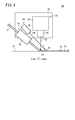
- FIG. 1 It is a schematic perspective view of the brazing device and a work which concerns on embodiment of this invention. It is an enlarged explanatory view of the main part of the brazing apparatus of FIG. It is an enlarged explanatory view of the main part of the brazing device which concerns on a modification. It is an enlarged explanatory view of the main part of the brazing device which concerns on another modification.
- the brazing material 12 is melted and solidified to form a weld bead 18 on the welded portion 16 of the work 14, and the works 14 are joined to each other. Is what you do.
- a weld bead 18 is formed on the outer surface side of the work 14 to obtain a bonded body 26. It can be particularly preferably applied when the workpieces 14 whose surface shape of the weld bead 18 affects the appearance of the bonded body 26 are joined together.
- the roof panel 22 and the side panel 24 are used as the work 14, and are arranged so as to extend in the front-rear direction (arrow X direction) of the vehicle body 20 at both ends in the vehicle width direction on the outer surface side of the roof panel 22.
- a case where a weld bead 18 is formed on the welded portion 16 by a brazing device 10 will be described as an example.
- the present invention is not particularly limited to this, and the brazing device 10 according to the present invention is applicable to the case of brazing various workpieces.
- the brazing contact device 10 mainly includes a brazing material supply mechanism 28, a laser irradiation mechanism 30, a transport mechanism 32, and a gas injection mechanism 34.
- the brazing material supply mechanism 28 supplies the wire-shaped brazing material 12 unwound from the reel portion (not shown) to the welded portion 16 of the work 14 via the guide portion 36.
- the laser irradiation mechanism 30 has a laser oscillator (not shown), an irradiation nozzle 38 connected to the laser oscillator via a transmission cable (not shown), and a holding portion 40 for holding the irradiation nozzle 38.
- the brazing material 12 supplied to the welded portion 16 of the above is irradiated with a laser. Specifically, the laser oscillated by the laser oscillator is irradiated toward the brazing material 12 from the irradiation port 42 provided at the tip of the irradiation nozzle 38.
- the brazing material 12 that has been irradiated with the laser and whose temperature has been raised melts to wet the welded portion 16, and then cools and solidifies to form a weld bead 18.
- the gas injection mechanism 34 is a portion including a welding bead 18 on the rear side (arrow X2 side) in the brazing traveling direction from the laser irradiation portion 44 of the brazing material 12 irradiated with the laser by the laser irradiation mechanism 30 (hereinafter, “gas”).
- the gas is injected toward the injection target portion 46 ”).
- the gas injection mechanism 34 has an injection nozzle 48 to which compressed gas is supplied from a gas source (not shown), and faces the gas injection target portion 46 from an injection port 50 provided at the tip of the injection nozzle 48. And inject gas.
- Examples of the gas injected by the gas injection mechanism 34 include dry air, argon gas, and the like.
- the injection nozzle 48 of the gas injection mechanism 34 is held by the holding portion 40 of the laser irradiation mechanism 30.
- the injection port 50 of the injection nozzle 48 is arranged behind the irradiation port 42 of the irradiation nozzle 38 in the brazing traveling direction.
- the gas injection mechanism 34 injects gas from the front side (arrow X1 side) of the gas injection target portion 46 toward the gas injection target portion 46 in the brazing traveling direction. That is, the gas injection mechanism 34 starts from the front side (arrow X1 side) in the brazing direction so that the gas injection direction Y (see FIG. 2) is inclined with respect to the laser irradiation direction Z (see FIG. 2). Gas is injected toward the rear side (arrow X2 side).
- the transport mechanism 32 is composed of, for example, an articulated robot, and supports a guide portion 36 of the brazing material supply mechanism 28 and a holding portion 40 of the laser irradiation mechanism 30 on a support frame 52 provided at the tip thereof. Therefore, the transport mechanism 32 moves the support frame 52 so that the guide portion 36, the irradiation nozzle 38, and the injection nozzle 48 are respectively aligned with the welded portion 16 along the brazing traveling direction. It can be moved together.
- the transport mechanism 32 may have a general configuration in which the support frame 52 can be moved three-dimensionally in the direction of brazing, the direction of approaching and separating from the welded portion 16 of the work 14. Therefore, the detailed description thereof will be omitted.
- the brazing device 10 according to the present embodiment is basically configured as described above. Next, as an example of the brazing method according to the present embodiment, the roof panel 22 and the side panel 24 are joined by forming a weld bead 18 on the welded portion 16 by using the brazing device 10. I will explain it by listing it.
- a brazing material supply step of supplying the brazing material 12 to the welded portion 16 is performed.
- the brazing material 12 and the welded portion 16 are preferably preheated so that the brazing material 12 can be easily melted and the welded portion 16 can be easily wetted with the melted brazing material 12.
- a laser irradiation step is performed in which the brazing material 12 supplied to the welded portion 16 is irradiated while the laser is moved along the brazing traveling direction to form the weld bead 18. That is, the brazing material 12 whose temperature has been raised by laser irradiation is melted to wet the welded portion 16 and then solidified by lowering the temperature. As a result, the weld bead 18 is formed on the welded portion 16. Sputtering and fume may occur from the brazing material 12 irradiated with the laser.
- gas is injected toward the gas injection target portion 46 from the front side of the gas injection target portion 46 in the brazing progress direction. That is, the gas is injected from the front side to the rear side in the brazing traveling direction so that the gas injection direction Y is inclined with respect to the laser irradiation direction Z. Further, the gas is injected from the gas injection port 50 arranged on the rear side of the laser irradiation port 42 in the brazing traveling direction.
- the brazing material 12 and the welded portion 16 before the laser irradiation that is, the brazing material 12 and the welded portion 16 before the laser irradiation mechanism 30, are cooled by the gas. Can be suppressed.
- the brazing material 12 since the brazing material 12 is not cooled, the brazing material 12 irradiated with the laser can be quickly melted.
- the welded portion 16 since the welded portion 16 is not cooled, the welded portion 16 can be easily wetted with the molten brazing material 12. As a result, the work 14 can be efficiently joined or satisfactorily joined via the weld bead 18.
- the brazing device 10 and the brazing method according to the present embodiment it is possible to suppress the formation of the weld bead 18 on which spatter and fume are deposited, and to join the work 14 efficiently and satisfactorily. Is possible. Therefore, even if brazing is performed, it is possible to suppress deterioration of the aesthetic design of the bonded body 26 (see FIG. 1) and extra work of scraping off spatter and fume accumulated on the weld bead 18. ..
- the gas is injected from the front side to the rear side in the brazing traveling direction so that the gas injection direction Y is inclined with respect to the laser irradiation direction Z. I decided. Further, in the brazing device 10 according to the above embodiment, the gas injection mechanism 34 moves from the front side to the rear side in the brazing traveling direction so that the gas injection direction Y is inclined with respect to the laser irradiation direction Z. It was decided to inject gas.
- the gas injection direction Y is not limited to being inclined with respect to the laser irradiation direction Z as described above.
- the distance between the laser irradiation portion 44 and the gas injection target portion 46 changes according to the traveling speed of the laser along the brazing traveling direction and the like. Therefore, it is preferable to appropriately set the gas injection direction Y according to the traveling speed of the laser and the like.
- the gas injection mechanism 34 may reduce the inclination angle of the gas injection direction Y with respect to the laser irradiation direction Z. Further, the gas injection mechanism 34 may inject gas toward the gas injection target portion 46 so that the gas injection direction Y is along the laser irradiation direction Z. These also make it possible to disperse spatter and fume well and keep them away from the molten brazing material 12.
- the gas injection mechanism 34 injects gas from above the gas injection target portion 46 toward the gas injection target portion 46 in the brazing progress direction. become.
- the gas injection port 50 of the gas injection mechanism 34 is arranged behind the laser irradiation port 42 of the laser irradiation mechanism 30 in the brazing traveling direction. And said.
- the gas injection port 50 can be brought close to the gas injection target portion 46, it is possible to efficiently inject gas to the gas injection target portion 46. Further, it becomes easy to reduce the inclination angle of the gas injection direction Y with respect to the laser irradiation direction Z and to make the gas injection direction Y follow the laser irradiation direction Z.
- the gas injection port 50 is not limited to being arranged behind the laser irradiation port 42 in the brazing traveling direction.
- the injection nozzle 48 of the gas injection mechanism 34 is arranged so that the injection port 50 is on the front side of the irradiation nozzle 38 in the brazing traveling direction. It may be held by the holding unit 40 so as to be.
- the gas injection mechanism 34 sets the gas injection direction Y to the laser irradiation direction Z. The gas is injected from the front side to the rear side in the brazing traveling direction so as to incline.
- the injection nozzle 48 of the gas injection mechanism 34 is held by the holding portion 40 of the laser irradiation mechanism 30. In this case, it becomes easy to reduce the size and simplification of the brazing devices 10 and 54.
- the present invention is not particularly limited to this, and the injection nozzle 48 of the gas injection mechanism 34 conveys the gas injection mechanism 34 separately from the laser irradiation mechanism 30, for example, as in the brazing device 56 according to the modification shown in FIG. It may be supported by the support frame 52 of the mechanism 32 (see FIG. 1).
- the injection nozzle 48 of the gas injection mechanism 34 is supported by the support frame 52 so that the injection port 50 is arranged in front of the irradiation port 42 of the irradiation nozzle 38 in the brazing traveling direction.
- the gas injection mechanism 34 injects gas from the front side of the gas injection target portion 46 in the brazing traveling direction. That is, the gas injection mechanism 34 injects the gas from the front side to the rear side in the brazing traveling direction so that the gas injection direction Y is inclined with respect to the laser irradiation direction Z.
- the injection nozzle 48 of the gas injection mechanism 34 has a laser irradiation mechanism 30 so that the injection port 50 is arranged behind the irradiation port 42 of the irradiation nozzle 38 in the brazing traveling direction. It may be supported by the support frame 52 separately from the support frame 52. In this case, the gas injection mechanism 34 may inject gas from above the gas injection target portion 46 toward the gas injection target portion 46 in the brazing traveling direction. Further, the gas injection mechanism 34 may inject gas from the front side of the gas injection target portion 46 toward the gas injection target portion 46 in the brazing traveling direction.
- the degree of freedom in adjusting the angle of the injection direction Y toward the gas injection target portion 46 is improved. It becomes possible to make it.
- Waxing device 12 ... Wax material 14 ... Work 16 ; Welded part 18 ... Welded bead 26 ... Joined body 28 ... Wax material supply mechanism 30 ... Laser irradiation mechanism 32 ... Conveying mechanism 34 ... Gas injection mechanism 42 ; Irradiation port 44 ... Laser irradiation point 46 ... Gas injection target part 50 ... Injection port
Landscapes
- Engineering & Computer Science (AREA)
- Physics & Mathematics (AREA)
- Optics & Photonics (AREA)
- Mechanical Engineering (AREA)
- Plasma & Fusion (AREA)
- Robotics (AREA)
- Chemical & Material Sciences (AREA)
- Materials Engineering (AREA)
- Laser Beam Processing (AREA)
Abstract
Description
14…ワーク 16…被溶接部
18…溶接ビード 26…接合体
28…ろう材供給機構 30…レーザ照射機構
32…搬送機構 34…ガス噴射機構
42…照射口 44…レーザ照射箇所
46…ガス噴射対象部分 50…噴射口
Claims (6)
- ろう材(12)を溶融させて固化させることで、ワーク(14)の被溶接部(16)に溶接ビード(18)を形成して前記ワーク同士を接合するろう接方法であって、
前記被溶接部に前記ろう材を供給するろう材供給工程と、
前記被溶接部に供給された前記ろう材に対して、レーザをろう付け進行方向に沿って移動させつつ照射して前記溶接ビードを形成するレーザ照射工程と、を有し、
前記レーザ照射工程では、前記レーザが照射される前記ろう材のレーザ照射箇所(44)よりも前記ろう付け進行方向の後側の前記溶接ビードを含む部分であるガス噴射対象部分(46)に向かって、前記ろう付け進行方向で前記ガス噴射対象部分上から又は前記ガス噴射対象部分よりも前側からガスを噴射する、ろう接方法。 - 請求項1記載のろう接方法において、
前記レーザ照射工程では、前記ガスの噴射方向が前記レーザの照射方向に対して傾斜するように、前記ろう付け進行方向の前側から後側に向かって前記ガスを噴射する、ろう接方法。 - 請求項1又は2記載のろう接方法において、
前記レーザ照射工程では、前記レーザの照射口(42)よりも前記ろう付け進行方向の後側に配置された前記ガスの噴射口(50)から前記ガスを噴射する、ろう接方法。 - ろう材(12)を溶融させて固化させることで、ワーク(14)の被溶接部(16)に溶接ビード(18)を形成して前記ワーク同士を接合するろう接装置(10、54、56)であって、
前記被溶接部に前記ろう材を供給するろう材供給機構(28)と、
前記被溶接部に供給された前記ろう材にレーザを照射するレーザ照射機構(30)と、
前記被溶接部に対して相対的に、前記ろう材供給機構及び前記レーザ照射機構をろう付け進行方向に移動させる搬送機構(32)と、
前記レーザ照射機構により前記レーザが照射される前記ろう材のレーザ照射箇所(44)よりも前記ろう付け進行方向の後側の前記溶接ビードを含む部分であるガス噴射対象部分(46)に向かって、前記ろう付け進行方向で前記ガス噴射対象部分上から又は前記ガス噴射対象部分よりも前側からガスを噴射するガス噴射機構(34)と、
を備える、ろう接装置。 - 請求項4記載のろう接装置において、
前記ガス噴射機構は、前記ガスの噴射方向が前記レーザの照射方向に対して傾斜するように、前記ろう付け進行方向の前側から後側に向かって前記ガスを噴射する、ろう接装置。 - 請求項4又は5記載のろう接装置において、
前記ガス噴射機構の前記ガスの噴射口(50)は、前記レーザ照射機構の前記レーザの照射口(42)よりも前記ろう付け進行方向の後側に配置される、ろう接装置。
Priority Applications (4)
| Application Number | Priority Date | Filing Date | Title |
|---|---|---|---|
| CA3133421A CA3133421A1 (en) | 2019-03-13 | 2020-01-07 | Brazing method and brazing apparatus |
| JP2021505539A JPWO2020183878A1 (ja) | 2019-03-13 | 2020-01-07 | ろう接方法及びろう接装置 |
| CN202080020886.XA CN113573835B (zh) | 2019-03-13 | 2020-01-07 | 钎焊方法和钎焊装置 |
| US17/437,438 US20220126387A1 (en) | 2019-03-13 | 2020-01-07 | Brazing method and brazing appratus |
Applications Claiming Priority (2)
| Application Number | Priority Date | Filing Date | Title |
|---|---|---|---|
| JP2019-045316 | 2019-03-13 | ||
| JP2019045316 | 2019-03-13 |
Publications (1)
| Publication Number | Publication Date |
|---|---|
| WO2020183878A1 true WO2020183878A1 (ja) | 2020-09-17 |
Family
ID=72426166
Family Applications (1)
| Application Number | Title | Priority Date | Filing Date |
|---|---|---|---|
| PCT/JP2020/000154 Ceased WO2020183878A1 (ja) | 2019-03-13 | 2020-01-07 | ろう接方法及びろう接装置 |
Country Status (5)
| Country | Link |
|---|---|
| US (1) | US20220126387A1 (ja) |
| JP (1) | JPWO2020183878A1 (ja) |
| CN (1) | CN113573835B (ja) |
| CA (1) | CA3133421A1 (ja) |
| WO (1) | WO2020183878A1 (ja) |
Citations (2)
| Publication number | Priority date | Publication date | Assignee | Title |
|---|---|---|---|---|
| EP1157770A2 (de) * | 2000-05-26 | 2001-11-28 | Sikora GmbH | Laserlötkopf |
| JP2014101021A (ja) * | 2012-11-20 | 2014-06-05 | Toyota Motor Corp | 車両用ルーフのレーザロウ付け方法 |
Family Cites Families (17)
| Publication number | Priority date | Publication date | Assignee | Title |
|---|---|---|---|---|
| JPH07144277A (ja) * | 1993-11-19 | 1995-06-06 | Hitachi Plant Eng & Constr Co Ltd | セルフシールドアーク溶接装置 |
| JPH10314954A (ja) * | 1997-05-15 | 1998-12-02 | Sony Corp | 被溶接体の溶接方法 |
| JP2000263275A (ja) * | 1999-03-19 | 2000-09-26 | Nec Corp | 多連スリット型エアブローノズルシステム |
| JP4583535B2 (ja) * | 2000-01-31 | 2010-11-17 | 本田技研工業株式会社 | レーザ溶接方法および装置 |
| US20090057373A1 (en) * | 2007-08-30 | 2009-03-05 | Gm Global Technology Operations, Inc. | Multi-Purpose End Effector for Welder |
| CN105555465B (zh) * | 2014-02-25 | 2017-05-10 | 松下知识产权经营株式会社 | 激光焊接方法 |
| US9718147B2 (en) * | 2014-03-07 | 2017-08-01 | Lincoln Global, Inc. | Method and system to start and use combination filler wire feed and high intensity energy source for root pass welding of the inner diameter of clad pipe |
| MX2017004265A (es) * | 2014-10-03 | 2018-01-25 | Honda Motor Co Ltd | Estructura del techo de un vehículo y método para la fabricación de la estructura del techo de un vehículo. |
| CN204524551U (zh) * | 2015-01-26 | 2015-08-05 | 大族激光科技产业集团股份有限公司 | 一种激光焊指形侧吹保护装置 |
| DE102015207279A1 (de) * | 2015-04-22 | 2016-10-27 | Ipg Laser Gmbh | Fügevorrichtung und Fügeverfahren |
| KR101713728B1 (ko) * | 2015-07-31 | 2017-03-09 | 현대자동차 주식회사 | 루프 레이저 브레이징 시스템용 브레이징 어셈블리 |
| CN105880833B (zh) * | 2016-05-21 | 2017-12-26 | 大连理工大学 | 一种核主泵屏蔽套的激光填丝焊接方法 |
| CN106270879A (zh) * | 2016-09-29 | 2017-01-04 | 哈尔滨工业大学(威海) | 一种镀层辅助调控的镁和钢异种材料激光熔钎焊方法 |
| CN207026790U (zh) * | 2017-07-28 | 2018-02-23 | 余小刚 | 一种适用于多种焊接工艺的焊接设备 |
| US20190061053A1 (en) * | 2017-08-24 | 2019-02-28 | GM Global Technology Operations LLC | Laser brazing of metal workpieces with relative movement between laser beam and filler wire |
| JP6921244B2 (ja) * | 2018-01-15 | 2021-08-18 | 本田技研工業株式会社 | ブレーズ装置及び方法 |
| DE102018001460A1 (de) * | 2018-02-23 | 2019-08-29 | Gunnar Bürkner | Verfahren und Vorrichtung zum stoffschlüssigen Verbinden metallischer Werkstoffe mittels zumindest einer Laserstrahlquelle |
-
2020
- 2020-01-07 JP JP2021505539A patent/JPWO2020183878A1/ja not_active Ceased
- 2020-01-07 CN CN202080020886.XA patent/CN113573835B/zh not_active Expired - Fee Related
- 2020-01-07 WO PCT/JP2020/000154 patent/WO2020183878A1/ja not_active Ceased
- 2020-01-07 US US17/437,438 patent/US20220126387A1/en not_active Abandoned
- 2020-01-07 CA CA3133421A patent/CA3133421A1/en not_active Abandoned
Patent Citations (2)
| Publication number | Priority date | Publication date | Assignee | Title |
|---|---|---|---|---|
| EP1157770A2 (de) * | 2000-05-26 | 2001-11-28 | Sikora GmbH | Laserlötkopf |
| JP2014101021A (ja) * | 2012-11-20 | 2014-06-05 | Toyota Motor Corp | 車両用ルーフのレーザロウ付け方法 |
Also Published As
| Publication number | Publication date |
|---|---|
| CA3133421A1 (en) | 2020-09-17 |
| CN113573835B (zh) | 2023-03-28 |
| JPWO2020183878A1 (ja) | 2021-11-04 |
| CN113573835A (zh) | 2021-10-29 |
| US20220126387A1 (en) | 2022-04-28 |
Similar Documents
| Publication | Publication Date | Title |
|---|---|---|
| US10888944B2 (en) | Method and system of using consumable with weld puddle | |
| JP3762676B2 (ja) | ワークの溶接方法 | |
| US7154065B2 (en) | Laser-hybrid welding with beam oscillation | |
| KR20160021827A (ko) | 고온 와이어 tig 위치설정된 열 제어를 위한 시스템 및 용접 방법 | |
| JP2005527383A (ja) | ビームオシレーションによるレーザー溶接 | |
| CN110170744B (zh) | 接合方法 | |
| KR20120104325A (ko) | 용접 방법 및 용접 장치 | |
| JP2009269036A (ja) | レーザ溶接方法 | |
| CN102677042A (zh) | 使用混合式激光工艺的覆层应用方法和设备 | |
| JP6031370B2 (ja) | ろう接装置及びろう接方法 | |
| JP5812527B2 (ja) | ホットワイヤレーザ溶接方法と装置 | |
| JP2007075872A (ja) | レーザブレージング接合工法 | |
| JP2013052445A (ja) | レーザ溶接方法 | |
| JP2002079371A (ja) | 板金ロー付方法及びロー付装置 | |
| WO2020183878A1 (ja) | ろう接方法及びろう接装置 | |
| JP2004237326A (ja) | 狭開先tig溶接装置 | |
| JP7467746B1 (ja) | 加工機および加工方法 | |
| JP2001205465A (ja) | レーザ−アーク複合溶接方法および溶接装置 | |
| JP5108321B2 (ja) | レーザ溶接方法 | |
| JP2016019984A (ja) | 構造物の溶接方法 | |
| JPH10244369A (ja) | 帯状電極を用いたアークとレーザとによる複合溶接方法およびその装置 | |
| JP2749376B2 (ja) | 溶接機における突合せ溶接方法およびその方法に用いる溶接ヘッド | |
| JP2026031120A (ja) | 溶接部材の製造方法及び製造装置 | |
| JP2012143765A (ja) | レーザー溶接方法 | |
| CN116372374A (zh) | 一种双工位激光焊接机及带涂层薄板激光焊接方法 |
Legal Events
| Date | Code | Title | Description |
|---|---|---|---|
| 121 | Ep: the epo has been informed by wipo that ep was designated in this application |
Ref document number: 20769171 Country of ref document: EP Kind code of ref document: A1 |
|
| ENP | Entry into the national phase |
Ref document number: 2021505539 Country of ref document: JP Kind code of ref document: A |
|
| ENP | Entry into the national phase |
Ref document number: 3133421 Country of ref document: CA |
|
| NENP | Non-entry into the national phase |
Ref country code: DE |
|
| 122 | Ep: pct application non-entry in european phase |
Ref document number: 20769171 Country of ref document: EP Kind code of ref document: A1 |