WO2020183582A1 - フライホイール蓄電システム - Google Patents
フライホイール蓄電システム Download PDFInfo
- Publication number
- WO2020183582A1 WO2020183582A1 PCT/JP2019/009783 JP2019009783W WO2020183582A1 WO 2020183582 A1 WO2020183582 A1 WO 2020183582A1 JP 2019009783 W JP2019009783 W JP 2019009783W WO 2020183582 A1 WO2020183582 A1 WO 2020183582A1
- Authority
- WO
- WIPO (PCT)
- Prior art keywords
- power storage
- flywheel
- voltage
- power
- storage system
- Prior art date
- Legal status (The legal status is an assumption and is not a legal conclusion. Google has not performed a legal analysis and makes no representation as to the accuracy of the status listed.)
- Ceased
Links
Images






Classifications
-
- H—ELECTRICITY
- H02—GENERATION; CONVERSION OR DISTRIBUTION OF ELECTRIC POWER
- H02J—ELECTRIC POWER NETWORKS; CIRCUIT ARRANGEMENTS OR SYSTEMS FOR SUPPLYING OR DISTRIBUTING ELECTRIC POWER; SYSTEMS FOR STORING ELECTRIC ENERGY
- H02J3/00—Circuit arrangements for AC mains or AC distribution networks
- H02J3/28—Arrangements for balancing of the load in networks by storage of energy
- H02J3/30—Arrangements for balancing of the load in networks by storage of energy using dynamo-electric machines coupled to flywheels
-
- H—ELECTRICITY
- H02—GENERATION; CONVERSION OR DISTRIBUTION OF ELECTRIC POWER
- H02J—ELECTRIC POWER NETWORKS; CIRCUIT ARRANGEMENTS OR SYSTEMS FOR SUPPLYING OR DISTRIBUTING ELECTRIC POWER; SYSTEMS FOR STORING ELECTRIC ENERGY
- H02J9/00—Circuit arrangements for emergency or stand-by power supply, e.g. for emergency lighting
- H02J9/04—Circuit arrangements for emergency or stand-by power supply, e.g. for emergency lighting in which the distribution system is disconnected from the normal source and connected to a standby source
- H02J9/06—Circuit arrangements for emergency or stand-by power supply, e.g. for emergency lighting in which the distribution system is disconnected from the normal source and connected to a standby source with automatic change-over, e.g. UPS systems
-
- Y—GENERAL TAGGING OF NEW TECHNOLOGICAL DEVELOPMENTS; GENERAL TAGGING OF CROSS-SECTIONAL TECHNOLOGIES SPANNING OVER SEVERAL SECTIONS OF THE IPC; TECHNICAL SUBJECTS COVERED BY FORMER USPC CROSS-REFERENCE ART COLLECTIONS [XRACs] AND DIGESTS
- Y02—TECHNOLOGIES OR APPLICATIONS FOR MITIGATION OR ADAPTATION AGAINST CLIMATE CHANGE
- Y02E—REDUCTION OF GREENHOUSE GAS [GHG] EMISSIONS, RELATED TO ENERGY GENERATION, TRANSMISSION OR DISTRIBUTION
- Y02E60/00—Enabling technologies; Technologies with a potential or indirect contribution to GHG emissions mitigation
- Y02E60/16—Mechanical energy storage, e.g. flywheels or pressurised fluids
Definitions
- This disclosure relates to a flywheel power storage system.
- Patent Document 1 discloses a flywheel power storage device.
- the generator field is fixed to the inertial body for energy storage, or the generator field is fixed to the inertial body shaft, and the armature part facing the coupling is the flywheel power storage device housing.
- the armature part facing the coupling is the flywheel power storage device housing.
- the purpose of this disclosure is to provide a flywheel power storage system that is effective in utilizing distributed power sources.
- the flywheel power storage system includes a flywheel power storage device that stores electrical energy as rotational energy of an inertial rotor, and a plurality of power conversion devices that charge and discharge the flywheel power storage device independently of each other. Be prepared.
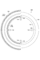
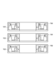
- FIG. 2 is a cross-sectional view taken along the line II-II in FIG. It is an enlarged view of the field part and the armature part. It is a figure which shows the modification of the field part and the armature part.
- FIG. 2 is a cross-sectional view taken along the line II-II in FIG. It is an enlarged view of the field part and the armature part. It is a figure which shows the modification of the field part and the armature part.
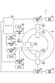
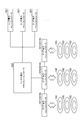
- It is a schematic diagram which shows the schematic structure of the flywheel power storage system which concerns on 1st Embodiment. It is a block diagram which illustrates the functional configuration of the area power machine controller. It is a block diagram which illustrates the functional structure of the power conversion apparatus. It is a schematic diagram which illustrates the functional structure of the acceleration / steady state switching part.
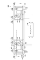
- FIG. 1 is a cross-sectional view showing a schematic configuration of a flywheel power storage device according to a first embodiment.
- FIG. 2 is a cross-sectional view taken along the line II-II in FIG.
- the flywheel power storage device 100 shown in FIG. 1 is a power storage device that stores electrical energy as rotational energy of an inertia rotor.
- the flywheel power storage device 100 includes a device housing 101 and an electric power generation unit 102 that performs bidirectional energy conversion between inertial energy and electric energy inside the device housing 101.
- the device housing 101 has a housing base 107 and a housing cover 108.
- the housing base 107 is an annular body (for example, a circular annular body), and is arranged horizontally so that the center thereof is vertical.
- the housing cover 108 covers the upper space of the housing base 107 to form an annular accommodation space.
- the motor generator 102 has an inertia rotor 103, a plurality of field portions 104, and a plurality of armature portions 106.
- the inertial rotor 103 is an annular body, and is housed in the storage space in an arrangement substantially concentric with the device housing 101.
- the inertia rotor 103 is rotatable around the center of the device housing 101 in the accommodation space.
- the plurality of field portions 104 are arranged so as to surround the rotation center of the inertia rotor 103 and are fixed to the inertia rotor 103.
- the plurality of field portions 104 may be arranged at least along a part of the circumference surrounding the rotation center of the inertia rotor 103, and may not necessarily be arranged over the entire circumference of the circumference. ..
- the plurality of armature units 106 are connected to a plurality of power conversion devices 160, which will be described later, and face the plurality of field units 104.
- the electric power generation unit 102 further has a field disk 105 fixed to the inertia rotor 103 so as to be perpendicular to the rotation center of the inertia rotor 103, and each of the plurality of field units 104 has a magnetization direction. It is fixed to the field disk 105 so as to be perpendicular to the field disk 105.
- the armature portion 106 faces at least one side of the field disk 105.
- the field disk 105 is an annular plate substantially concentric with the inertia rotor 103, and is fixed to the upper part of the inertia rotor 103.
- the field disk 105 is housed in the storage space of the device housing 101 together with the inertia rotor 103.
- the plurality of field portions 104 include a plurality of outer field portions 112 (outer peripheral side field portions) arranged along the outer circumference of the field disk 105, and a plurality of inner field portions arranged along the inner circumference of the field disk 105.
- the plurality of armature portions 106 include the portion 122 (inner peripheral side field portion), the outer armature portion 114 (outer peripheral side armature portion) facing the plurality of outer field portions 112, and the plurality of inner fields. It includes an inner armature portion 124 (inner peripheral side armature portion) facing the magnetic portion 122.
- the magnetization directions of the outer field portions 112 adjacent to each other along the outer circumference of the field disk 105 are opposite to each other. That is, on the outer circumference of the field disk 105, outer field portions 112 whose magnetization directions are opposite to each other are alternately arranged. Similarly, the magnetization directions of the inner field portions 122 adjacent to each other along the inner circumference of the field disk 105 are also opposite to each other.
- the outer armature portion 114 is fixed on the housing base 107 by the support column 109, and the height of the outer armature portion 114 can be adjusted by the height of the support column 109.
- the inner armature portion 124 is also fixed on the housing base 107 by the support column 109, and the height of the inner armature portion 124 can be adjusted by the height of the support column 109.
- the electric power generation unit 102 for example, by supplying a three-phase AC to the outer armature unit 114, rotational torque is generated in a plurality of outer field units 112 and the inertia rotor 103 is rotationally driven to generate electric energy. Converted to inertial (mechanical) energy and stored.
- the rotating magnetic fields generated by the plurality of inner field portions 122 with the rotation of the inertial rotor 103 generate an induced voltage in the inner armature portion 124, and a current flows through the external circuit connected to the inner armature portion 124. Therefore, it has the function of converting the stored inertial (mechanical) energy into electrical energy. It is also possible to reverse the functions of the outside and the inside of the motor generator 102.
- the flywheel power storage device 100 may be a magnetic levitation type power storage device that rotates the inertia rotor 103 in a state of being magnetically levitated.
- the flywheel power storage device 100 further includes a levitation fixed magnet 131 and a levitation rotating magnet 132.
- the levitation fixed magnet 131 is provided on the housing base 107 of the device housing 101, and the levitation rotating magnet 132 is provided below the inertia rotor 103.
- the magnetization directions of the levitation fixed magnet 131 and the levitation rotating magnet 132 are opposite to each other.
- the repulsive force generated between the levitation fixed magnet 131 and the levitation rotating magnet 132 causes the inertia rotor 103 to levitate from the housing base 107.
- the levitation fixed magnet 131 and the levitation rotating magnet 132 may be permanent magnets or electromagnets.
- the flywheel power storage device 100 further includes, for example, a magnetic ring 133, gap adjusting electromagnets 134 and 135, and a gap controller 136.
- the magnetic ring 133 is made of a soft magnetic material such as iron, and forms a magnetic flux magnetic path of the gap adjusting electromagnets 134 and 135.
- the magnetic ring 133 is arranged so as to be substantially concentric with the inertia rotor 103, and is fixed to the inner circumference of the inertia rotor 103.
- the magnetic ring 133 also serves to reinforce the rigidity (strength) of the inertia rotor 103.
- the gap adjusting electromagnet 134 faces the magnetic ring 133 in the radial direction.
- the gap adjusting electromagnet 134 has a built-in gap sensor that detects the gap variate in the radial direction (the gap variate between the magnetic ring 133 and the gap adjusting electromagnet 134).
- the flywheel power storage device 100 may have a plurality of gap adjusting electromagnets 134 symmetrically arranged with respect to the rotation center of the inertia rotor 103.
- the gap adjusting electromagnet 135 faces the magnetic ring 133 in the direction of gravity.
- the gap adjusting electromagnet 135 has a built-in gap sensor that detects a gap variate in the direction of gravity (gap variate between the magnetic ring 133 and the gap adjusting electromagnet 135).
- the flywheel power storage device 100 may have a plurality of gap adjusting electromagnets 135 arranged symmetrically with respect to the rotation center of the inertia rotor 103.
- the gap controller 136 adjusts the magnetic flux generated by the gap adjusting electromagnets 134 and 135 based on the signal of the gap sensor of the gap adjusting electromagnets 134 and 135, and maintains the gap variate in the vicinity of the target value.
- the brake is applied due to viscous friction with the air.
- the device main body may be provided with the following measures.
- the device housing 101 has a closed structure in which the joint surface between the housing base 107 and the housing cover 108 is sealed, and the accommodation space is in a vacuum state. As a result, wind loss (surface friction loss with air) when the inertia rotor 103 rotates is reduced.
- FIG. 3 is an enlarged view of the field part and the armature part.
- the force acting between the field portion 104 and the armature portion 106 becomes small in both the axial direction and the radial direction of the inertia rotor 103.
- the gap adjustment in the axial direction and the radial direction by the gap adjusting electromagnets 134 and 135 can be facilitated, and the loss generated by the gap adjusting electromagnets 134 and 135 can be reduced.
- the field portion 104 is provided so that both side surfaces of the field disk 105 have opposite polarities, and the armature portion 106 has at least one set of coils facing each other on both sides of the field disk 105.
- the outer field portion 112 is composed of an outer field magnet 113 penetrating the field disk 105
- the inner field portion 122 is also composed of an inner field magnet 123 penetrating the field disk 105.
- the outer field magnet 113 and the inner field magnet 123 are, for example, permanent magnets.
- the field disk 105 is made of a non-magnetic material. This structure makes it possible to reduce the thickness of the field disk 105.
- the outer armature portion 114 has an outer armature portion yoke 115 and a set of outer armature portion coils 116 (coils).
- the outer armature portion yoke 115 is a ring-shaped member along the outer circumference of the field disk 105, and is made of a soft magnetic material such as iron.
- the cross section of the outer armature portion yoke 115 is U-shaped open toward the center side of the field disk 105, and the inner surface of the outer armature portion yoke 115 faces both sides of the field disk 105.
- One outer armature coil 116 is attached to the upper inner surface of the outer armature yoke 115 and faces the upper surface of the field disk 105.
- the other outer armature coil 116 is attached to the lower inner surface of the outer armature yoke 115 and faces the lower surface of the field disk 105.
- the upper and lower outer armature coil 116 are both air-core coils.
- the inner armature portion 124 has an inner armature portion yoke 125 and a set of inner armature portion coils 126 (coils).
- the inner armature portion yoke 125 is a ring-shaped member along the inner circumference of the field disk 105, and is made of a soft magnetic material such as iron.
- the cross section of the inner armature portion yoke 125 is U-shaped open on the outer peripheral side of the field disk 105, and the inner surface of the inner armature portion yoke 125 faces both sides of the field disk 105.
- One inner armature coil 126 is attached to the upper inner surface of the inner armature yoke 125 and faces the upper surface of the field disk 105.
- the other inner armature coil 126 is attached to the lower inner surface of the inner armature yoke 125 and faces the lower surface of the field disk 105.
- the upper and lower inner armature coil 126 are both air-core coils.
- the force generated between the armature portion 106 and the field portion 104 in the radial direction becomes small. .. Further, if the magnetic field generated by the current flowing through the armature portion 106 is configured to penetrate the field disk 105, the forces acting on both sides of the field portion 104 in the axial direction cancel each other out. Further, since the outer armature coil 116 and the inner armature coil 126 are air-core, the forces generated on both sides of the field 104 in the axial direction are both reduced. Therefore, the resultant force acting on the field portion 104 in the axial direction becomes small.
- FIG. 4 is a diagram showing a modified example of the field portion and the armature portion.
- FIG. 4 shows a detailed structure of a modified example of the flywheel motor generator. According to the structure of FIG. 4, since the force acting between the field portion 104 and the armature portion 106 becomes large, it is effective for miniaturization of the motor generator portion 102. Similar to the structure shown in FIG. 3, the gap adjustment in the radial direction and the axial direction is performed by the gap adjusting electromagnets 134 and 135.
- the outer armature coil 116 and the inner armature coil 126 are not air-core.
- a core protruding from the inner surface of the outer armature yoke 115 is inserted into the outer armature coil 116.
- the outer armature coil 116 is fitted between the cores protruding from the inner surface of the outer armature yoke 115.
- a core protruding from the inner surface of the inner armature portion yoke 125 is inserted into the inner armature portion coil 126.
- the inner armature coil 126 is fitted between the cores protruding from the inner surface of the inner armature yoke 125.
- FIG. 4 shows an example composed of a pair of magnets arranged on both sides of the field disk 105 instead of the magnet penetrating the field disk 105.
- the outer field portion 112 is composed of an outer field magnet 143 on the upper side of the field disk 105 and an outer field magnet 144 on the lower side of the field disk 105.
- the inner field portion 122 is composed of an inner field magnet 153 on the upper side of the field disk 105 and an inner field magnet 154 on the lower side of the field disk 105.
- the field disc 105 includes an outer rotor disc 145, an inner rotor disc 155, and a magnet holder 146.
- the outer rotor disk 145 and the inner rotor disk 155 are annular plates concentric with the inertial rotor 103, and are made of a soft magnetic material such as iron.
- the outer rotor disk 145 is interposed between the outer field magnets 143 and 144.
- the inner rotor disk 155 is interposed between the inner field magnets 153 and 154.
- the magnet holder 146 is made of a non-magnetic material and holds the outer field magnets 143 and 144, the outer rotor disk 145, the inner field magnets 153 and 154, and the inner rotor disk 155.
- the magnetization directions of the outer field magnets 143 and 144 may be opposite to each other.
- the magnetization directions of the inner field magnets 153 and 154 may be opposite to each other.
- both sides of the field disk 105 have the same polarity (magnetic flux symmetric structure).
- the magnetization directions of the outer field magnets 143 and 144 may be the same as each other.
- the magnetization directions of the inner field magnets 153 and 154 may be the same as each other.
- both sides of the field disk 105 have opposite polarities (magnetic flux penetration structure).
- the outer rotor disk 145 and the inner rotor disk 155 can be omitted.
- the power conversion device 160 is connected to each of the outer armature portion 114 and the inner armature portion 124 of the flywheel power storage device 100.
- a flow of energy for storing generated power in the inertial rotor 103 and a flow of energy for converting the stored energy into power are used, which can convert power in both directions.
- FIG. 5 is a schematic view showing a schematic configuration of the flywheel power storage system 1.
- the flywheel power storage system 1 includes the flywheel power storage device 100 described above and a plurality of power conversion devices 160 that charge and discharge the flywheel power storage device 100 independently of each other.
- Each of the plurality of power conversion devices 160 is interposed between the armature portion 106 of the flywheel power storage device 100 and the charge / discharge system, and is the reverse of the armature portion 106 side of the flywheel power storage device 100 and the armature portion 106. Power conversion is performed with the side (the charge / discharge system side).
- the charge / discharge system mainly charges the flywheel power storage device 100 with surplus power (hereinafter referred to as "power supply system 191") and a system that mainly consumes the power discharged from the flywheel power storage device 100 (hereinafter referred to as “power supply system 191"). It may be either “power consumption system 192").
- a power supply system 191 is connected to the outer armature portion 114 of the flywheel power storage device 100 via a power conversion device 160.
- Specific examples of the power supply system 191 include distributed power sources such as a wind power generation system and a solar power generation system.
- a power consumption system 192 is connected to the inner armature portion 124 of the flywheel power storage device 100 via the power conversion device 160.
- the power consumption system 192 include consumer equipment such as factories and houses.
- the definition of the power consumption system 192 is for convenience only, and the power consumption system 192 may charge the flywheel power storage device 100 with surplus power.
- a factory, a house, or the like may have a distributed power source such as a wind power generation system or a solar power generation system, and the surplus electric power may be charged to the flywheel power storage device 100.
- the stored energy of the inertial rotor 103 is converted into electric energy by the field part 104 and the armature part 106, and the power is converted through the power conversion device 160. It is supplied to the consumption system 192.
- the surplus electric power generated in the power consumption system 192 is sent to the armature portion 106 side via the power conversion device 160, and the electric energy is converted into rotational energy by the armature portion 106 and the field portion 104 to perform inertia. It is stored in the rotor 103. In this way, the direction of energy flow through the power converter 160 is bidirectional.
- any one of the armature units 106 may be connected to the external system 193 (commercial power supply system) via the power conversion device 160.
- the power conversion device 160 may be interposed between the armature unit 106 and the external system 193.
- the power conversion device 160 performs power conversion between the power charged / discharged to the armature portion 106 of the flywheel power storage device 100 and the power input / output from the power supply system and the power consumption system. ..
- the power converter 160 is an AC / AC power converter.
- the AC / AC power converter may be a forward converter and an inverter connected by a DC link circuit, or may be a matrix converter that performs AC / AC conversion without going through a DC link circuit.
- the power converter 160 may be, for example, an AC / DC power converter or a DC / DC power converter, depending on the form of input / output power.
- At least one of the plurality of power conversion devices 160 may perform power conversion so that the voltage on the opposite side of the armature unit 106 follows the target value.
- at least one of the plurality of power converters 160 is such that when the power on the opposite side of the armature unit 106 is AC power, the voltage amplitude and phase on the opposite side of the armature unit 106 follow the target value. Power conversion may be performed.
- At least one of the plurality of power conversion devices 160 performs power conversion in an acceleration mode in which the voltage on the armature portion 106 side follows a target value for acceleration of the inertia rotor 103 in response to an increase in the rotation speed of the inertia rotor 103.
- the flywheel power storage system 1 may further include an area power machine controller 501. As shown in FIG. 5, the area power machine controller 501 is connected to each power conversion device 160, and sends a command regarding power conversion performed there to each power conversion device 160.
- the area power machine controller 501 is a computer system composed of a processor, a memory, a storage, and an input / output interface circuit, and the processor realizes each control function by executing a program loaded from the storage into the memory.
- the storage is a non-volatile storage medium (eg, hard disk or flash memory) that can be read by a computer.
- the storage includes a storage area of a program for forming a steady operation command unit 502, a start operation command unit 503, and a command switching unit 504, which will be described later.
- the input / output interface circuit performs signal conversion necessary for interfacing with a signal external circuit input / output to the processor.
- the area power machine controller 501 is not necessarily limited to the one that configures each function by a program. For example, at least a part of the functions may be configured by a dedicated logic circuit or an ASIC (Application Specific Integrated Circuit) that integrates the logic circuit.
- ASIC Application Specific Integrated Circuit
- FIG. 6 is a block diagram illustrating the functional configuration of the area power machine controller 501.
- the area power machine controller 501 has a steady operation command unit 502, a start operation command unit 503, and a command switching unit 504.
- the steady operation command unit 502 outputs the magnitude of the rated voltage of each power supply system 191 connected to the outer armature unit 114, the external system 193, and each power consumption system 192 connected to the inner armature unit 124. As a command, an output voltage command is sent to the power converter 160.
- the power conversion device 160 that has acquired the output voltage command from the steady operation command unit 502 performs power conversion so that the voltage on the opposite side of the corresponding armature unit 106 follows this output voltage command.
- the flywheel power storage device 100 is charged and discharged while the voltage on the opposite side of the armature unit 106 is maintained in the vicinity of the output voltage command.
- the power conversion device 160 detects the phase of the AC voltage of the connected power supply system 191 or the external system 193 or the power consumption system 192, and the detected phase and the output voltage command acquired from the steady operation command unit 502.
- the output voltage command is generated based on the above, and the voltage on the opposite side of the armature unit 106 is made to follow the output voltage command.
- the start-up operation command unit 503 generates a start-up rotation speed command when starting the flywheel power storage device 100.
- a start rotation speed command is a rotation speed command for the inertia rotor 103, and is a rotation speed command that increases from zero rotation speed to a predetermined rotation speed in a predetermined acceleration time.
- the predetermined rotation speed is, for example, the rotation speed during normal operation defined as a mechanical specification for the inertia rotor 103.
- the increase of the rotation speed command within the predetermined acceleration time may be due to a linear pattern or an S-shaped pattern in which the S-shaped time is set.
- the start rotation speed command generated by the start operation command unit 503 is sent to the power conversion device 160 connected to the power supply system 191 or the external system 193, which is defined for start control.
- the number of power conversion devices 160 to which the start rotation speed command is sent may be one or a plurality.
- the power conversion device 160 that has received the start-up rotation speed command outputs an AC voltage that raises the inertia rotor 103 from the rotation speed zero to the rotation speed for the steady mode according to the start-up rotation speed command.
- the power conversion device 160 converts the start rotation speed command into a start frequency command for the outer armature unit 114 to which the power conversion device 160 is connected.
- This starting frequency command corresponds to the frequency of the induced voltage generated in the outer armature portion 114 when the inertia rotor 103 rotates at the rotation speed according to the starting rotation speed command.
- the power conversion device 160 determines the output voltage by, for example, V / f constant control, and outputs the output voltage to the outer armature unit 114.
- the inertial rotor 103 starts and accelerates to the rotation speed during normal operation in accordance with the start rotation speed command.
- the flywheel power storage device 100 shifts to steady operation.
- the area power machine controller 501 first stops the power conversion device 160 used for starting / accelerating the inertia rotor 103.
- the flywheel power storage device 100 is separated from all of the power supply system 191 and the power consumption system 192 and the external system 193, and the inertia rotor 103 continues to rotate by inertia due to its own moment of inertia, and each armature portion 106 Induces a voltage corresponding to the rotation speed of the inertia rotor 103.
- the area power machine controller 501 activates the total power conversion device 160, and starts outputting an output voltage command from the steady operation command unit 502 to the power conversion device 160.
- the command to the power conversion device 160 used to start the inertia rotor 103 is switched from the command by the start operation command unit 503 to the command by the steady operation command unit 502 by the command switching unit 504.
- the command switching unit 504 sends a start rotation speed command from the start operation command unit 503 to the power conversion device 160 used for the start / acceleration.
- the command switching unit 504 stops sending the starting rotation speed command.
- the command switching unit 504 switches the command to the power conversion device 160 used for starting / accelerating to the output voltage command by the steady operation command unit 502 at the timing when the total power conversion device 160 is started.
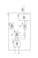
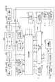
- FIG. 7 is a block diagram illustrating the functional configuration of the power conversion device 160.
- the power conversion device 160 includes a power conversion unit 161, an output filter 162, a system voltage detection unit 163, an input filter 164, a flywheel voltage detection unit 165, a current sensor 167, and a control unit 166.
- the power conversion unit 161 is composed of a semiconductor switching element, and the semiconductor switching element switches according to a switching command output from the control unit 166 to perform power conversion between input power and output power.
- the circuit configuration of the semiconductor switching element of the power converter 161 differs depending on whether the power converter 160 is an AC / AC power converter, an AC / DC power converter, or a DC / DC power converter.
- the power converter 161 is an AC / AC power converter, and among them, a PWM converter, which is a form of a forward converter, and an inverter are connected by a DC link circuit.
- the PWM converter and the inverter have the same circuit configuration, but for convenience, the one in which the AC side is connected to the armature unit 106 is referred to as the PWM converter, and the one in which the AC side is connected to the power system is referred to as the inverter.
- the DC link circuit has a current detection unit, which detects the magnitude and direction of the DC current of the DC link circuit and inputs the detected information to the control unit 166.
- the direction of the direct current is detected, for example, by setting the magnitude of the current flowing from the PWM converter to the inverter as a positive value and the magnitude of the current flowing from the inverter to the PWM converter as a negative value.
- the output filter 162 is provided to remove switching noise contained in the current output from the power conversion unit 161 and has a cutoff frequency of at least twice the switching frequency of the power conversion unit, for example, a reactor L or a reactor.
- the system voltage detection unit 163 detects the voltage on the system connection side of the output filter 162. For example, in the case of line voltage, or in the case of multiphase AC, the voltage between the neutral points is divided by a voltage dividing resistor. It is for detection. The detected voltage is input to the control unit 166.
- the input filter 164 is provided to remove harmonic components contained in the current flowing between the power conversion unit 161 and the armature unit 106, and for example, a reactor L, an LC filter, an LCL filter, or the like is used. ..
- the flywheel voltage detection unit 165 detects the induced voltage generated in the armature unit 106, and like the system voltage detection unit 163, divides, for example, the line voltage or, in the case of multiphase AC, the voltage between the neutral points. It detects the voltage divided by the pressure resistance. The detected voltage is input to the control unit 166.
- the current sensor 167 detects the current flowing between the output filter 162 and the system voltage detection unit 163. The detected current is input to the control unit 166.
- the control unit 166 is a computer system composed of a processor, a memory, a storage, and an input / output interface circuit, and the processor realizes each control function by executing a program loaded from the storage into the memory.
- the storage includes a voltage amplitude calculation unit 170, a voltage phase frequency detection unit 171, an output voltage command generation unit 172, a voltage amplitude calculation unit 173, a voltage phase frequency detection unit 174, a DC voltage command setting unit 175, and an input current command unit 177, which will be described later. , Input voltage command generation unit 178, rotation frequency conversion unit 179, V / f command unit 180, acceleration voltage command generation unit 181, acceleration / steady switching unit 182, and switching command output unit 183. including.
- the input / output interface circuit performs signal conversion necessary for interfacing with a signal external circuit input / output to the processor.
- the control unit 166 is not necessarily limited to the one that configures each function by a program. For example, at least a part of the functions may be configured by a dedicated logic circuit or an ASIC (Application Specific Integrated Circuit) that integrates the logic circuit.
- ASIC Application Specific Integrated Circuit
- control unit 166 includes a voltage amplitude calculation unit 170, a voltage phase frequency detection unit 171, an output voltage command generation unit 172, a voltage amplitude calculation unit 173, a voltage phase frequency detection unit 174, and a DC voltage.
- the control unit 166 switches the control of the power conversion device 160 between the acceleration mode and the steady mode. This switching is performed by the switching operation of the acceleration / steady switching unit 182.
- the acceleration / steady switching unit 182 includes a voltage command for the inverter of the power conversion unit 161, a voltage command for the PWM converter of the power conversion unit 161, a frequency detection value, an amplitude calculation value, and a phase detection value input to the input voltage command generation unit 178. To switch between acceleration mode and steady mode.
- the flow of electric power is in the direction from the electric power system to the flywheel power storage device 100. Therefore, the inverter of the power conversion unit 161 controls the input power, and the PWM converter controls the output power to the flywheel power storage device 100.
- the inverter command becomes an input voltage command generated by the input voltage command generation unit 178 based on the frequency, amplitude, phase, and current flowing through the DC link circuit of the voltage detected by the system voltage detection unit 163, and is PWM.
- the converter command is an acceleration voltage command generated by the acceleration voltage command generation unit 181 based on the startup rotation speed command acquired from the area power machine controller 501.
- the power conversion device 160 outputs an AC voltage of a certain magnitude from the inverter of the power conversion unit 161, and the bidirectional power flow depends on the magnitude relationship between the AC voltage and the actual AC voltage of the power system. Is created.
- the power conversion device 160 outputs an AC voltage corresponding to the frequency, amplitude, phase, and current flowing through the DC link circuit of the voltage detected by the flywheel voltage detection unit 165 from the PWM converter of the power conversion unit 161 to output the power conversion unit 160.
- the PWM converter of the power conversion unit 161 also creates a flow in the same direction as the flow of power in the inverter of 161.
- the inverter command is a system output voltage command generated by the output voltage command generation unit 172 based on the output voltage command acquired from the area power machine controller 501 and the phase of the actual AC voltage of the power system.
- the PWM converter command is an input voltage command generated by the input voltage command generation unit 178 based on the frequency, amplitude, phase, and current of the induced voltage generated in the armature unit 106 and the current flowing through the DC link circuit.
- the acceleration / steady switching unit 182 of the control unit 166 is in a state A corresponding to the steady mode shown in FIG. 8 and a state corresponding to the acceleration mode. Switch B.
- the inverter command is connected to the output (output voltage command) of the output voltage command generation unit 172
- the PWM converter command is connected to the output (input voltage command) of the input voltage command generation unit 178
- the input voltage command is generated.
- the AC voltage frequency f 1 input to the unit 178 and the input voltage phase ⁇ 1 input to the input current command unit 177 and the input voltage command generation unit 178 are the outputs (f IN and ⁇ IN) of the voltage phase frequency detection unit 174. )
- the input voltage amplitude E 1 input to the input voltage command generation unit 178 is connected to the output (E IN ) of the voltage amplitude calculation unit 173.
- the inverter command is connected to the output (input voltage command) of the input voltage command generation unit 178
- the PWM converter command is connected to the output (acceleration voltage command) of the acceleration voltage command generation unit 181
- the input voltage command is provided.
- the AC voltage frequency f 1 input to the generation unit 178 and the input voltage phase ⁇ 1 input to the input current command unit 177 and the input voltage command generation unit 178 are the outputs (f OUT and ⁇ ) of the voltage phase frequency detection unit 171. is connected to OUT), the input voltage amplitude E 1 which is input to the input voltage command generating unit 178 is connected to the output of the voltage amplitude calculating unit 170 (E OUT).
- the voltage amplitude calculation unit 170 calculates the amplitude of the voltage detected by the system voltage detection unit 163. For example, when the power system is a three-phase AC system, the voltage values of each of the three phases detected by the system voltage detection unit 163 are converted into three-phase and two-phase, and the sum of square roots of the sum of squares of the obtained two-phase voltage values is calculated. By doing so, the amplitude is calculated.
- the voltage phase frequency detection unit 171 is, for example, a PLL (Phase Locked Loop), and detects the phase and frequency of the voltage detected by the system voltage detection unit 163.
- the phase reference is, for example, the time point of negative ⁇ positive zero cross of the first phase voltage.
- the output voltage command generation unit 172 acquires the output voltage command E2 from the area power machine controller 501, the system voltage frequency f OUT and the system voltage phase ⁇ OUT from the system voltage phase frequency detection unit 151, and the system current from the current sensor 167. I OUT is acquired, and an output voltage command is generated based on these acquired values.
- the output voltage command is a command for the voltage output from the inverter of the power conversion unit 161 to the power system side in the steady mode.
- FIG. 9 is a block diagram illustrating the functional configuration of the output voltage command generation unit 172.
- the output voltage command generation unit 172 includes a three-phase two-phase conversion unit 172a, a current amplitude calculation unit 172b, a proportional / integral calculation unit 172c, 172d, and a two-phase three-phase conversion unit 172e.
- the three-phase two-phase conversion unit 172a performs three-phase two-phase conversion on the system current I OUT based on the system voltage phase ⁇ OUT , and the current component Id in phase with the system voltage and a current whose phase is 90 degrees different from that.
- the component Iq is calculated.
- the current amplitude calculation unit 172b calculates the square root of the sum of squares of the current component Id and the current component Iq as the current amplitude.
- the proportional / integral calculation unit 172c performs a proportional / integral calculation on the deviation between the current amplitude and the current component Id to calculate the addition component with respect to the output voltage command E2.
- the proportional / integral calculation unit 172d performs a proportional / integral calculation on the current component Iq to calculate a subtraction component for the output voltage command E2.
- the two-phase three-phase conversion unit 172e calculates the correction value of the output voltage command by adding the addition component and subtracting the subtraction component to the output voltage command E2, and the system voltage phase ⁇ OUT with respect to the correction value.
- the output voltage command is calculated by performing 2-phase and 3-phase conversion based on.
- the current component Id is an effective current that causes charging / discharging of the flywheel power storage device 100.
- the current component Iq is a reactive current that does not cause charge / discharge to the flywheel power storage device 100, and is mainly generated by the output filter 162.
- the output voltage command is corrected so that the current component Id approaches the current amplitude and the current component Iq approaches zero. As a result, the influence of the output filter 162 is reduced, and charging / discharging of the flywheel power storage device 100 is executed.
- control unit 166 converts the power according to the output voltage command E2 set by the area power machine controller 501 by the voltage amplitude calculation unit 170, the voltage phase frequency detection unit 171 and the output voltage command generation unit 172. Generates a command for the AC voltage output from the device 160 to the power system.
- the voltage amplitude calculation unit 173 calculates the voltage amplitude detected by the flywheel voltage detection unit 165. For example, when the voltage output from the armature 106 of the flywheel power storage device 100 is a three-phase AC voltage, the voltage values of each of the three phases detected by the flywheel voltage detection unit 165 are converted into three-phase and two-phase to obtain the voltage. The amplitude is calculated by calculating the sum of square roots of the sum of squares of each voltage value of the two phases.
- the voltage phase frequency detection unit 174 is, for example, a PLL (Phase Locked Loop), and detects the phase and frequency of the voltage detected by the flywheel voltage detection unit 165.
- the phase reference is, for example, the time point of negative ⁇ positive zero cross of the first phase voltage.
- the DC voltage command setting unit 175 sets the voltage command value of the DC link circuit of the power conversion unit 161. This command value is set to, for example, the larger value between the rated peak value of the AC voltage on the power system side and the rated peak value of the AC voltage output from the armature unit 106.
- the multiplier 176 calculates the DC power of the DC link circuit by multiplying the DC current value of the DC link circuit detected by the current detection unit of the power conversion unit 161 and the DC voltage command output by the DC voltage command setting unit 175. To do.
- the input current command unit 177 divides the DC power of the DC link circuit output by the multiplier 176 by the AC voltage amplitude E 1 output by the acceleration / steady switching unit 182, and multiplies the division result by 1 / ⁇ 3.
- the input current command Iac is calculated and output to the input voltage command generation unit 178.
- the input voltage command generation unit 178 generates an input voltage command in which the power factor on the input side is, for example, as follows. That is, the power factor is 1 when the power flows into the power conversion device 160 from the input side, and the power factor is -1 when the power flows out from the input side into the power conversion device 160. Therefore, the input voltage command generation unit 178 acquires the AC voltage frequency f 1 , the input voltage phase ⁇ 1 , and the input voltage amplitude E 1 from the acceleration / steady switching unit 182 in addition to the input current command Iac.
- the voltages generated across the reactor L of the output filter 162 and the input filter 164 are the AC voltage detected by the system voltage detection unit 163 and the flywheel voltage detection unit 165, respectively. Produces a phase difference of 90 degrees. Therefore, the input voltage command (amplitude command of the AC voltage on the input side) E in which the power factor on the input side is 1 can be obtained by the following equation.
- L fill is the total inductance of the reactor per phase in the filter.
- phase difference ⁇ can be obtained by the following equation.
- ⁇ tan -1 (2 ⁇ f 1 , L file ⁇ I ac / E 1 ) ⁇ ⁇ ⁇ (2)
- ⁇ determines positive and negative signs according to the operating state of the flywheel power storage device 100 and the flow of electric power inside the power conversion device 160. Specifically, in the steady mode, if the direction of the current flowing through the DC link circuit detected by the current detection unit of the power conversion unit 161 is the direction from the PWM converter of the power conversion unit 161 toward the inverter, ⁇ is negative. The value shall be a positive value if the direction is from the inverter to the PWM converter.
- ⁇ is set to a positive value. If the direction is from the inverter to the PWM converter, the value is negative.
- the input voltage command generator 178 is an input voltage command which is a command of the voltage output from the power conversion device 160 to the input side. Is determined by, for example, the following equation.
- the control unit 166 includes an acceleration / steady switching unit 182, a voltage amplitude calculation unit 173, a voltage phase frequency detection unit 174, a DC voltage command setting unit 175, a multiplier 176, an input current command unit 177, and an input voltage command generation unit. 178 generates an AC voltage command to be output to the input side in order to flow a current having a power factor of 1 or -1 according to the internal power flow to the input side of the power conversion device 160.
- the rotation speed frequency conversion unit 179 receives a start rotation speed command from the area power machine controller 501, and issues the start frequency command to rotate the inertia rotor 103 at the rotation speed specified by the start rotation speed command. Convert to f.
- the starting frequency f is a command of the frequency of the AC voltage output from the power converter 160 to, for example, the outer armature portion 114 side.
- the V / f command unit 180 maintains a relationship between the frequency and amplitude of the AC voltage applied to, for example, the outer armature unit 114 in order to rotate the inertia rotor 103, and the starting frequency from the rotation frequency frequency conversion unit 179 according to this relationship.
- the starting voltage amplitude command V corresponding to the command f is obtained.
- the relationship between the frequency and the amplitude may be expressed by an equation, or some combinations of the frequency and the voltage are set, and two of these setting combinations are set by the starting frequency command f. It may be selected and the starting voltage amplitude command V may be determined by interpolation.
- the accelerating voltage command generation unit 181 uses the starting frequency command f and the voltage amplitude command V to determine the accelerating voltage command by, for example, the following equation.
- Vu V ⁇ sin (2 ⁇ ⁇ f ⁇ t)
- Vv V ⁇ sin (2 ⁇ ⁇ f ⁇ t-2 ⁇ / 3)
- Vw V ⁇ sin (2 ⁇ ⁇ f ⁇ t-4 ⁇ / 3)
- t is the elapsed time from the start of startup, with the start of startup as zero.
- control unit 166 stores the flywheel according to the start rotation speed command commanded from the area power machine controller 501 in the acceleration mode by the rotation speed frequency conversion unit 179, the V / f command unit 180, and the acceleration voltage command generation unit 181.
- the power conversion device 160 In order to activate the inertia rotor 103 of the device 100, the power conversion device 160 generates an AC voltage command that commands a voltage to be output to, for example, the outer armature 114 side of the flywheel power storage device 100.
- the control unit 166 generates three voltage commands, an output voltage command, an input voltage command, and an acceleration voltage command, by the output voltage command generation unit 172, the input voltage command generation unit 178, and the acceleration voltage command generation unit 181. To do. These three voltage commands are given by the acceleration / steady switching unit 182 to the inverter and the PWM converter of the power conversion unit 161 as follows. That is, in the steady mode, the inverter command: system output voltage command PWM converter command: input voltage command, and in the acceleration operation, the inverter command: input voltage command PWM converter command: acceleration voltage command.
- the acceleration / steady switching unit 182 outputs the above inverter command and PWM converter command to the switching command output unit 183.
- the switching command output unit 183 acquires the inverter command C INV and the PWM converter command C PWM from the acceleration / steady switching unit 182, and turns on / off the inverter of the power conversion unit 161 and the semiconductor switching element of the PWM converter based on these commands. Generate a switching command.
- the switching command output unit 183 generates a switching command based on the magnitude relationship between each of the inverter command C INV and the PWM converter command C PWM and the triangular wave by, for example, a known triangular wave comparison method, and outputs the switching command to the power conversion unit 161.
- the switching command generation method by the switching command output unit 183 is not limited to the triangular wave comparison method.
- an inverter command and a PWM converter command given as three-phase voltage commands may be converted into commands based on a space vector, and a switching command may be generated by a known space vector method.
- the switching command output unit 183 converts the three-phase voltage command into a two-phase voltage command by three-phase two-phase conversion, and the amplitude from this two-phase voltage command. And a method of obtaining the phase.
- the configuration and operation of the control unit 166 when the power conversion unit 161 has a configuration in which the inverter and the PWM converter are connected by a DC link circuit have been described.
- the input voltage command generation unit 178 of the control unit 166 becomes unnecessary.
- the acceleration / steady switching unit 182 may input the input voltage phase ⁇ 1 and the input voltage amplitude E 1 to the switching command output unit 183 instead of the PWM converter command.
- the switching command output unit 183 selects the phase of the input voltage connected to the output side to output the voltage from the input voltage phase ⁇ 1 and the input voltage amplitude E 1, and switches to output the output voltage determined by the inverter command.
- the switching command may be generated by the PWM method of a known matrix converter that generates the command.
- At least one of the plurality of power conversion devices 160 has an operating state in a charge / discharge mode in which the flywheel power storage device 100 is charged / discharged, and a non-charge / discharge mode in which the flywheel power storage device 100 is not charged / discharged. , May be configured to switch based on the current amplitude on the opposite side of the flywheel power storage device 100. Switching between the non-charge / discharge mode and the charge / discharge mode can be executed, for example, in the output voltage command generation unit 172.
- the difference voltage between the voltage of the power system and the output voltage of the power conversion unit 161 is applied to the reactor L of the output filter 162.
- the difference voltage is in phase or out of phase (180 degree phase difference) with the voltage of the power system. Since the current flowing through the reactor L lags 90 degrees from this difference voltage, the difference voltage deviates by 90 degrees from the voltage of the power system in both in-phase and reverse-phase, and the output current to the power system becomes an invalid current.
- the power conversion device 160 calculates the addition component by the proportional / integral calculation unit 172c and the proportional / integral calculation unit 172d.
- the first current threshold value may be set to a value larger than the second current threshold value.
- the method of switching between the charge / discharge mode and the non-charge / discharge mode is not limited to the above method using the output voltage command generation unit 172.
- the power conversion device 160 may be configured to stop the power conversion by the power conversion unit 161 in the non-charge / discharge mode.
- the power conversion device 160 that selects the state B by the acceleration / steady switching unit 182 and generates an acceleration voltage command may be, for example, any of the power conversion devices 160 connected to the outer armature unit 114. If there is a power conversion device 160 connected to the external system 193, the acceleration / steady switching unit 182 of the control unit 166 of the power conversion device 160 selects the state B, which is necessary for accelerating the inertia rotor 103 from the external system 193. Can be supplied with electric power.
- the power conversion in the steady mode is continued by the power conversion device 160 connected to the external system 193, if there is surplus power in the entire flywheel power storage device 100, it is external. Electric power can be sent to the system 193 side, and when there is a demand from the flywheel power storage device 100, electric power can be supplied from the external system 193 side. Therefore, once the acceleration of the inertia rotor 103 is completed, the power conversion in the acceleration mode becomes unnecessary unless the external system 193 is in a power failure state.
- the power conversion device 160 interposed between the armature unit 106 and the external system 193 sets the operating state of the charge / discharge mode and the operating state of the non-charge / discharge mode based on the information regarding the rotation speed of the inertial rotor 103. It may be configured to switch.
- the information regarding the rotation speed of the inertia rotor 103 may be, for example, an actually measured value of the rotation speed of the inertia rotor 103 by a sensor or the like, or a detected value of a value that correlates with the rotation speed of the inertia rotor 103.
- values that correlate with the rotation speed of the inertia rotor 103 include the frequency of the flywheel voltage that is the output of the voltage phase frequency detection unit 174, the induced voltage generated in the armature unit 106, and the like.
- the power converter 160 starts the calculation of the addition component by the proportional / integral calculation unit 172c and the calculation of the subtraction component by the proportional / integral calculation unit 172d. It may be configured.
- the power conversion device 160 stops the calculation of the addition component by the proportional / integral calculation unit 172c and the calculation of the subtraction component by the proportional / integral calculation unit 172d when the induced voltage generated in the armature unit 106 falls below the second frequency threshold. It may be configured to (ie, make the addition and subtraction components zero).
- the first frequency threshold value may be set to a value larger than the second frequency threshold value.
- the method of switching between the charge / discharge mode and the non-charge / discharge mode in this case is not limited to the above method using the output voltage command generation unit 172.
- the power conversion device 160 may be configured to stop the power conversion by the power conversion unit 161 in the non-charge / discharge mode.
- the area power machine controller 501 may monitor the information regarding the rotation speed of the inertia rotor 103, and the area power machine controller 501 may switch the operation / stop of the power conversion device 160.
- the flywheel power storage system may include a plurality of flywheel power storage systems 1.
- the flywheel power storage devices 100 of the plurality of flywheel power storage systems 1 may be arranged so as to rotate the inertia rotor 103 around the same axis (tandem superposition structure). ). It is not necessary for each of the plurality of flywheel power storage systems 1 to include the area power machine controller 501, and one area power machine controller 501 may perform demand control of the plurality of flywheel power storage systems 1. According to this modification, it is possible to provide a flywheel power storage system that can cover a wider area without increasing the size of the device.
- the flywheel power storage system 1 has a plurality of armatures 106 in a plurality of field portions 104 integrated with the inertia rotor 103 of the flywheel power storage device 100.
- flywheel power storage system 1 By connecting one of the plurality of armature units 106 to the external system 193 via the power conversion device 160, if there is a surplus in the entire flywheel power storage system 1, power is sold to the external system 193 side. When there is a demand from the flywheel power storage system 1, power can be purchased from the external system 193, and the power transfer of the entire system can be stabilized.
- the storage capacity of the flywheel power storage system 1 is increased, power is supplied and supplied from the external system 193 at a low price within the daily power transaction arbitrage price, and the power is stored in the flywheel power storage device 100.
- the power is stored in the flywheel power storage device 100.
- the inertial rotors 103 superposed and arranged may be connected and integrated.
- the rotational energy of the inertial rotor 103 can be shared among the plurality of flywheel power storage devices 100, and the stored energy can be stabilized.
- the flywheel power storage system 2 includes a plurality of flywheel power storage systems 1 and a relay power conversion device 260 (relay power conversion device).
- FIG. 11 shows two flywheel power storage systems 1 (hereinafter, referred to as “first power storage system 1A” and “second power storage system 1B”), but the number of flywheel power storage systems 1 is limited to two. I can't.
- the relay power conversion device 260 charges and discharges between the flywheel power storage device 100 of the first power storage system 1A and the flywheel power storage device 100 of the second power storage system 1B.
- the relay power conversion device 260 performs power conversion so that either the voltage on the first power storage system 1A side or the voltage on the second power storage system 1B side follows the target value.
- the relay power conversion device 260 may be configured to switch which of the voltage on the first power storage system 1A side and the voltage on the second power storage system 1B side follows the target value according to the setting.
- the plurality of armature units 106 in each flywheel power storage device 100 further include a relay armature unit 204, and the relay power conversion device 260 connects the relay armature units 204 to each other.
- the relay armature section 204 is connected to the other flywheel power storage system 1 unlike the other armature section 106.
- the power transfer in each flywheel power storage system 1 is performed not only with the external system but also with other similar flywheel power storage systems 1, thereby increasing the power demand.
- the common area can be expanded.
- the relay armature portion 204 may be outside or inside the inertia rotor 103. In other words, the relay armature portion 204 may be either the outer armature portion 114 or the inner armature portion 124.
- the configuration of the relay power conversion device 260 includes common parts with the power conversion device 160, the configuration of the relay power conversion device 260 will be described below focusing on the differences from the power conversion device 160.
- the relay power conversion device 260 includes a power conversion unit 261, a filter 262, a voltage detection unit 263, a filter 264, a voltage detection unit 265, current sensors 267, 268, and a control unit. It has 266 and.
- the voltage detection unit 263 is the same as the system voltage detection unit 163, except that the connection destination is the relay armature unit 204 of the first power storage system 1A.
- the voltage detection unit 265 is the same as the flywheel voltage detection unit 165, except that the connection destination is the relay armature unit 204 of the second power storage system 1B.
- the power conversion unit 261 and the filters 262 and 264 are the same as the power conversion unit 161, the output filter 162, and the input filter 164, respectively. Similar to the current sensor 167, the current sensor 267 detects the current flowing between the voltage detection unit 263 and the filter 262. The current sensor 268 detects the current flowing between the voltage detection unit 265 and the filter 264.
- the control unit 266 replaces the voltage amplitude calculation units 170, 173 and the voltage phase frequency detection units 171, 174 of the control unit 166 with the voltage amplitude calculation units 270, 273 and the voltage phase frequency detection units 271,274, respectively, and further directions.
- a switching unit 284 is added.
- the voltage amplitude calculation unit 270 calculates the voltage amplitude (voltage amplitude E 12 ) detected by the voltage detection unit 263 in the same manner as the voltage amplitude calculation unit 170.
- the voltage phase frequency detection unit 271 detects the phase (voltage phase ⁇ 12 ) and the frequency (voltage frequency f 12 ) of the voltage detected by the voltage detection unit 263, similarly to the voltage phase frequency detection unit 171.
- the voltage amplitude calculation unit 273 calculates the voltage amplitude (voltage amplitude E 11 ) detected by the voltage detection unit 265 in the same manner as the voltage amplitude calculation unit 173. Similar to the voltage phase frequency detection unit 174, the voltage phase frequency detection unit 274 detects the voltage phase (voltage phase ⁇ 11 ) and the frequency (voltage frequency f 11 ) detected by the voltage detection unit 263.
- the first power storage system 1A side is the power system side of the control unit 166
- the second power storage system 1B side is the flywheel power storage device 100 side of the control unit 166. Switching between the corresponding state C and the state D corresponding to the first power storage system 1A side being the flywheel power storage device 100 side in the control unit 166 and the second power storage system 1B side being the power system side in the control unit 166. ..
- the current I 12 detected by the current sensor 267 is the current I OUT
- the voltage amplitude E 12 calculated by the voltage amplitude calculation unit 270 is the voltage amplitude E OUT
- the voltage phase frequency detection unit 271 The voltage phase ⁇ 12 calculated by the above is defined as the voltage phase ⁇ OUT
- the voltage frequency f 12 calculated by the voltage phase frequency detection unit 271 is defined as the voltage frequency f OUT
- the voltage amplitude E 11 calculated by the voltage amplitude calculation unit 273 is defined as the voltage amplitude E IN
- the voltage phase ⁇ 11 calculated by the voltage phase frequency detection unit 274 is defined as the voltage phase ⁇ IN.
- the voltage frequency f 11 calculated by the detection unit 274 is defined as the voltage frequency f IN .
- the inverter command C INV is the power conversion command C 12 to the first power storage system 1A side
- the PWM converter command C PWM is the power conversion command C 11 to the second power storage system 1B side.
- the voltage amplitude E 12 calculated by the voltage amplitude calculation unit 270 is defined as the voltage amplitude E IN
- the voltage phase ⁇ 12 calculated by the voltage phase frequency detection unit 271 is defined as the voltage phase ⁇ IN
- the voltage frequency f 12 calculated by the phase frequency detection unit 271 is defined as the voltage frequency f IN
- the current I 11 detected by the current sensor 268 is defined as the current I OUT
- the voltage amplitude E 11 calculated by the voltage amplitude calculating unit 273 is defined as the voltage amplitude E OUT
- the voltage phase ⁇ 11 to be generated is defined as the voltage phase ⁇ OUT
- the voltage frequency f 11 calculated by the voltage phase frequency detection unit 274 is defined as the voltage frequency f OUT .
- the inverter command C INV is the power conversion command C 11 to the second power storage system 1B side
- the PWM converter command C PWM is the power conversion command C 12 to the first power storage system 1A side.
- the relay power conversion device 260 outputs a voltage to one of the two relay armature units 204 in response to a voltage command determined by, for example, equation (4).
- the relay power conversion device 260 can output a voltage of a predetermined magnitude according to the output voltage command acquired from the area power machine controller 501 to one relay armature unit 204 side.
- the relay power conversion device 260 gives one of the two relay armature units 204 the power to start the flywheel power storage device 100 having the relay armature unit 204. It is also possible to supply from one of the relay armature units 204.
- the flywheel power storage system 2 is 1) Since power can be exchanged not only with the external system but also with other similar flywheel power storage systems, the shared area of power demand can be expanded, and it depends on fluctuating natural energy. In the power generation system, the generated power is not wasted, it is efficient and economical, and the uniqueness of power transfer in the power storage system area can be enhanced.
- the plurality of flywheel power storage systems 1 in the second embodiment may have the tandem superposition structure shown in the modified example of the first embodiment.
- the flywheel power storage system 1 has a flywheel power storage device 100 that stores electrical energy as rotational energy of the inertial rotor 103, and a plurality of power conversions that charge and discharge the flywheel power storage device 100 independently of each other.
- the device 160 is provided.
- the flywheel power storage system 1 includes a plurality of power conversion devices 160 that charge and discharge the flywheel power storage device 100 independently of each other.
- various power consumption systems 192 and various power supply systems 191 can be connected while absorbing the deviation between the consumption time zone and the supply time zone.
- the flywheel power storage device 100 may be a magnetic levitation type power storage device that rotates the inertia rotor 103 in a state of being magnetically levitated. In this case, the energy loss in the inertia rotor 103 can be reduced, and the distributed power source can be further effectively utilized. Further, by magnetically levitating the inertial rotor 103, deterioration of mechanical elements is suppressed, so that the life of the flywheel power storage device 100 is expected to be extended.
- the flywheel power storage device 100 is connected to a plurality of field portions 104 arranged so as to surround the rotation center of the inertia rotor 103 and fixed to the inertia rotor 103, and to the plurality of field portions 104, respectively, connected to the plurality of power conversion devices 160. It has a plurality of armature units 106 facing each other, and each of the plurality of power conversion devices 160 performs power conversion between the armature unit 106 side of the flywheel power storage device 100 and the opposite side of the armature unit 106. You may.
- the flywheel power storage device 100 has a field disk 105 fixed to the inertia rotor 103 so as to be perpendicular to the center of rotation, and the field portion 104 has a field so that the magnetization direction is perpendicular to the field disk 105. It is fixed to the magnetic disk 105, and the armature portion 106 may face at least one side of the field disk 105. In this case, the force generated between the armature portion 106 and the field portion 104 in the radial direction becomes small. Therefore, even if a plurality of armature portions 106 involved in charging and discharging independently of each other face the field disk 105, the position of the field disk 105 in the radial direction is likely to be stable.
- the field portion 104 is provided so that both sides of the field disk 105 have opposite polarities, and the armature unit 106 generates a magnetic field that faces both sides of the field disk 105 and penetrates the field disk 105. It may have at least one set of coils (outer armature coil 116 or inner armature coil 126). In this case, since the forces generated on both sides of the field portion 104 cancel each other out in the axial direction of the field disk 105, the position of the field disk 105 in the axial direction is likely to be stable.
- the coil (outer armature coil 116 or inner armature coil 126) may be an air-core coil. In this case, since the force generated on both sides of the field portion 104 in the axial direction is reduced, the position of the field disk 105 in the axial direction is more likely to be stable.
- the field disk 105 is annular, and the plurality of field portions 104 include a plurality of outer field portions 112 arranged along the outer circumference of the field disk 105 and a plurality of inner fields arranged along the inner circumference of the field disk.
- the plurality of armature portions 106 include a magnetic portion 122, and the plurality of armature portions 106 include an outer armature portion 114 facing the plurality of outer field portions 112 and an inner armature portion 124 facing the plurality of inner field portions 122. You may be. In this case, more armature portions 106 can be arranged by using both the inner circumference and the outer circumference of the field disk 105.
- At least one of the plurality of power conversion devices 160 may perform power conversion so that the voltage on the opposite side of the armature unit 106 follows the target value.
- the control of each power conversion device 160 since the control of each power conversion device 160 is simplified, the system can be easily constructed. In addition, it becomes easy to add or delete the power conversion device 160 after the system is constructed.
- At least one of the plurality of power converters 160 is powered so that when the power on the opposite side of the armature unit 106 is AC power, the voltage amplitude and phase on the opposite side of the armature unit 106 follow the target value.
- the conversion may be performed.
- At least one of the plurality of power conversion devices 160 has an operating state in a charge / discharge mode in which the flywheel power storage device 100 is charged / discharged, and a non-charge / discharge mode in which the flywheel power storage device 100 is not charged / discharged. , May be switched based on the current amplitude on the opposite side of the flywheel power storage device 100. In this case, for example, by cutting a minute charge / discharge, the acceleration / deceleration frequency of the inertia rotor 103 can be suppressed and the stability of the storage state can be improved.
- At least one of the plurality of power conversion devices 160 may be interposed between the armature portion 106 of the flywheel power storage device 100 and the external system 193. In this case, since the excess or deficiency of the storage level of the flywheel power storage device 100 is supplemented by the external system 193, the stability of the power storage state can be improved.
- the power conversion device 160 interposed between the armature portion 106 of the flywheel power storage device 100 and the external system 193 is used in the operation state of the charge / discharge mode for charging / discharging the flywheel power storage device 100 and in the flywheel power storage device 100.
- the operating state of the non-charging / discharging mode in which charging / discharging is not performed may be switched based on the information regarding the rotation speed of the inertial rotor 103. In this case, by limiting the connection between the flywheel power storage device 100 and the external system 193, the stored power can be used more effectively.
- At least one of the plurality of power conversion devices 160 performs power conversion in an acceleration mode in which the voltage on the armature portion 106 side follows a target value for acceleration of the inertia rotor 103 in response to an increase in the rotation speed of the inertia rotor 103.
- the voltage on the opposite side of the armature portion 106 may be switched to the power conversion in the steady mode to follow a predetermined target value. In this case, the flywheel power storage device 100 can be easily started.
- the flywheel power storage system 1 includes a plurality of flywheel power storage systems 1 which are the above-mentioned flywheel power storage systems 1, and the flywheel power storage devices 100 of the plurality of flywheel power storage systems 1 have an inertia rotor 103 around the same axis. They may be arranged so as to rotate so as to overlap each other. In this case, more flywheel power storage systems 1 can be installed in the limited space.
- the flywheel power storage system 2 includes the flywheel power storage system 1A and the second power storage system 1B, the flywheel power storage device 100 of the first power storage system 1A, and the flywheel power storage system 1B of the second power storage system 1B.
- a relay power conversion device 260 that charges and discharges between the device 100 and the device 100 may be provided. In this case, by electrically connecting the two flywheel power storage systems 1 to each other, it is possible to connect more power consumption systems 192 and power supply systems 191 to ensure stable use of power as a whole system. it can.
- the relay power conversion device 260 may perform power conversion so that either the voltage on the first power storage system 1A side or the voltage on the second power storage system 1B side follows a predetermined target value.
- the relay power conversion device 260 may switch which of the voltage on the first power storage system 1A side and the voltage on the second power storage system 1B side follows the target value according to the setting. In this case, the relationship between the flywheel power storage systems 1 can be flexibly set according to the actual situation.
- the area power machine controller 501 is arranged for each group.
- a total power management controller 520 that integrates a plurality of area power machine controllers 501 may be provided.
- the plurality of area power machine controllers 501 may be divided into a plurality of groups, the master controller 501A and the slave controller 501B may be set for each group, and the plurality of master controllers 501A may be integrated by the total power management controller 520.
Landscapes
- Engineering & Computer Science (AREA)
- Power Engineering (AREA)
- Business, Economics & Management (AREA)
- Emergency Management (AREA)
- Stand-By Power Supply Arrangements (AREA)
- Supply And Distribution Of Alternating Current (AREA)
- Connection Of Motors, Electrical Generators, Mechanical Devices, And The Like (AREA)
Abstract
フライホイール蓄電システム1は、慣性ロータ103の回転エネルギーとして電気エネルギーを蓄えるフライホイール蓄電装置100と、フライホイール蓄電装置100に対する充放電を互いに独立して行う複数の電力変換装置160と、を備える。
Description
本開示は、フライホイール蓄電システムに関する。
特許文献1にはフライホイール蓄電装置が開示されている。特許文献1のフライホイール蓄電装置では、エネルギー貯蔵の為の慣性体にカップリング、もしくは慣性体シャフトに発電機界磁部を固定し、これに対向する電機子部は、フライホイール蓄電装置匡体に固定し、これら界磁部、電機子部を駆動制御することにより、電力を慣性エネルギーとして貯蔵する際にはモータとして、また慣性エネルギーを電力変換する際には発電機として駆動制御することにより、電力平準化システムを実現する。
本開示は、分散電源の活用に有効なフライホイール蓄電システムを提供することを目的とする。
本開示の一側面に係るフライホイール蓄電システムは、慣性ロータの回転エネルギーとして電気エネルギーを蓄えるフライホイール蓄電装置と、フライホイール蓄電装置に対する充放電を互いに独立して行う複数の電力変換装置と、を備える。
本開示によれば、分散電源の活用に有効なフライホイール蓄電システムを提供することができる。
以下、実施形態について図を参照して説明する。なお、同一の構成又は同一機能を有する構成については同一の符号を付することにより、重複説明を適宜省略する。
<第1実施形態>
まず、図1を参照しつつ、第1実施形態に係る多重電機子型フライホイール蓄電装置の機械的構成について説明する。図1は、第1実施形態に係るフライホイール蓄電装置の概略構成を示す断面図である。図2は、図1中のII-II線による断面図である。
まず、図1を参照しつつ、第1実施形態に係る多重電機子型フライホイール蓄電装置の機械的構成について説明する。図1は、第1実施形態に係るフライホイール蓄電装置の概略構成を示す断面図である。図2は、図1中のII-II線による断面図である。
図1に示すフライホイール蓄電装置100は、慣性ロータの回転エネルギーとして電気エネルギーを蓄える蓄電装置である。フライホイール蓄電装置100は、装置匡体101と、その内部に、慣性エネルギーと電気エネルギーの双方向エネルギー変換を行う電動発電部102とを有する。装置匡体101は、匡体ベース107と、匡体カバー108とを有する。匡体ベース107は環状体(例えば円形環状体)であり、その中心が鉛直となるように水平に配置されている。匡体カバー108は、匡体ベース107の上部空間を覆い環状の収容空間を構成している。
電動発電部102は、慣性ロータ103と、複数の界磁部104と、複数の電機子部106とを有する。慣性ロータ103は環状体であり、装置匡体101と実質的に同心となる配置で上記収容空間内に収容されている。慣性ロータ103は、上記収容空間内において、装置匡体101の中心まわりに回転自在となっている。複数の界磁部104は、慣性ロータ103の回転中心を囲むように並び慣性ロータ103に固定されている。なお、複数の界磁部104は、少なくとも慣性ロータ103の回転中心を囲む円周の一部に沿って並んでいればよく、必ずしも当該円周の全周に亘って並んでいなくてもよい。複数の電機子部106は、後述の複数の電力変換装置160にそれぞれ接続され複数の界磁部104に対向する。
一例として、電動発電部102は、慣性ロータ103の回転中心に垂直となるように慣性ロータ103に固定された界磁ディスク105を更に有し、複数の界磁部104のそれぞれは、磁化方向が界磁ディスク105に垂直となるように界磁ディスク105に固定されている。電機子部106は界磁ディスク105の少なくとも片面に対向している。
界磁ディスク105は、慣性ロータ103と実質的に同心の環状板であり、慣性ロータ103の上部に固定されている。界磁ディスク105は、慣性ロータ103と共に装置匡体101の上記収容空間に収容されている。複数の界磁部104は、界磁ディスク105の外周に沿って並ぶ複数の外側界磁部112(外周側界磁部)と、界磁ディスク105の内周に沿って並ぶ複数の内側界磁部122(内周側界磁部)とを含み、複数の電機子部106は、複数の外側界磁部112に対向する外側電機子部114(外周側電機子部)と、複数の内側界磁部122に対向する内側電機子部124(内周側電機子部)とを含む。界磁ディスク105の外周に沿って隣り合う外側界磁部112同士の磁化方向は互いに逆向きとなっている。すなわち、界磁ディスク105の外周においては、磁化方向が互いに逆向きの外側界磁部112が交互に並んでいる。同様に、界磁ディスク105の内周に沿って隣り合う内側界磁部122同士の磁化方向も互いに逆向きとなっている。
外側電機子部114は、支柱109により匡体ベース107上に固定されており、支柱109の高さによって外側電機子部114の高さが調節可能となっている。同様に、内側電機子部124も支柱109により匡体ベース107上に固定されており、支柱109の高さによって内側電機子部124の高さが調節可能となっている。この電動発電部102の構成において、外側電機子部114に例えば三相交流を供給することにより複数の外側界磁部112に回転トルクを発生させ慣性ロータ103を回転駆動することで、電気エネルギーを慣性(機械)エネルギーに変換貯蔵させる。また、慣性ロータ103の回転に伴い複数の内側界磁部122により作り出される回転磁界が内側電機子部124に誘起電圧を発生させ、内側電機子部124に接続された外部回路に電流が流れることにより、貯蔵された慣性(機械)エネルギーを電気エネルギーへと変換させる機能をもつ。また、電動発電部102の外側及び内側の機能を逆にすることも可能である。
外側電機子部114及び内側電機子部124は、慣性ロータ103の周方向に複数個設けることも可能である。こうして設けた複数の外側電機子部114及び内側電機子部124のそれぞれから給電線を出すことで、複数の電力系統(電力消費系統又は電力供給系統)に接続できるようにすることも可能である。
フライホイール蓄電装置100は、慣性ロータ103を磁気により浮上させた状態で回転させる磁気浮上型の蓄電装置であってもよい。一例として、フライホイール蓄電装置100は、浮上用固定磁石131と、浮上用回転磁石132とを更に有する。浮上用固定磁石131は、装置匡体101の匡体ベース107上に設けられ、浮上用回転磁石132は、慣性ロータ103の下部に設けられている。浮上用固定磁石131及び浮上用回転磁石132の磁化方向は互いに逆向きとなっている。これにより、浮上用固定磁石131及び浮上用回転磁石132の間に生じる反発力が慣性ロータ103を匡体ベース107から浮上させる。浮上用固定磁石131及び浮上用回転磁石132は、永久磁石であってもよいし、電磁石であってもよい。
磁気浮上支持構造の場合、界磁ディスク105と電機子部106との間のギャップを一定にする制御が必要となる。そこでフライホイール蓄電装置100は、例えば磁性体リング133と、ギャップ調整用電磁石134,135と、ギャップコントローラ136とを更に有する。
磁性体リング133は、例えば鉄等の軟質磁性材料により構成されており、ギャップ調整用電磁石134,135の磁束磁路をなす。磁性体リング133は、慣性ロータ103と実質的に同心となるように配置され、慣性ロータ103の内周に固定されている。磁性体リング133は、慣性ロータ103の剛性(強度)補強の役割も兼ねている。
ギャップ調整用電磁石134は、ラジアル方向で磁性体リング133に対向する。ギャップ調整用電磁石134は、ラジアル方向におけるギャップ変量(磁性体リング133とギャップ調整用電磁石134との間のギャップ変量)を検出するギャップセンサを内蔵している。フライホイール蓄電装置100は、慣性ロータ103の回転中心に対して対称配置された複数のギャップ調整用電磁石134を有してもよい。
ギャップ調整用電磁石135は、重力方向で磁性体リング133に対向する。ギャップ調整用電磁石135は、重力方向におけるギャップ変量(磁性体リング133とギャップ調整用電磁石135との間のギャップ変量)を検出するギャップセンサを内蔵している。フライホイール蓄電装置100は、慣性ロータ103の回転中心に対して対称配置された複数のギャップ調整用電磁石135を有してもよい。
ギャップコントローラ136は、このギャップ調整用電磁石134,135の上記ギャップセンサの信号に基づいて、ギャップ調整用電磁石134,135が生じる磁束を調節し、上記ギャップ変量を目標値の近傍に維持する。 慣性ロータ103が大気中で回転すると、空気との粘性摩擦によりブレーキがかかることになる。これを低減させるため、装置本体は、以下のような手段が講じられていてもよい。
装置匡体101は、匡体ベース107と匡体カバー108との接合面がシールされた密閉構造となっており、上記収容空間が真空状態とされている。これにより、慣性ロータ103回転時の風損(空気との表面摩擦損)が低減されている。
図3は、界磁部及び電機子部の拡大図である。図3の構造によれば、界磁部104と電機子部106との間に作用する力が、慣性ロータ103のアキシアル方向及びラジアル方向のいずれにおいても小さくなる。これにより、ギャップ調整用電磁石134,135による、アキシアル方向及びラジアル方向のギャップ調整を容易にし、ギャップ調整用電磁石134,135で発生する損失を低減させることができる。
図3において、界磁部104は、界磁ディスク105の両面側を互いに逆極性にするように設けられ、電機子部106は、界磁ディスク105の両面にそれぞれ対向する少なくとも一組のコイルを有する。例えば外側界磁部112は界磁ディスク105を貫通する外側界磁磁石113により構成されており、内側界磁部122も界磁ディスク105を貫通する内側界磁磁石123により構成されている。外側界磁磁石113及び内側界磁磁石123は、例えば永久磁石である。界磁ディスク105は非磁性材料により構成されている。この構造により、界磁ディスク105の薄型化が可能となっている。
外側電機子部114は、外側電機子部ヨーク115と一組の外側電機子部コイル116(コイル)とを有する。外側電機子部ヨーク115は、界磁ディスク105の外周に沿うリング状部材であり、鉄等の軟質磁性材料により構成されている。外側電機子部ヨーク115の断面は界磁ディスク105の中心側に開いたU字状であり、外側電機子部ヨーク115の内面は界磁ディスク105の両面に対向している。一方の外側電機子部コイル116は、外側電機子部ヨーク115の上側内面に取り付けられており、界磁ディスク105の上面に対向する。他方の外側電機子部コイル116は、外側電機子部ヨーク115の下側内面に取り付けられており、界磁ディスク105の下面に対向する。上側及び下側の外側電機子部コイル116はいずれも空芯コイルである。
内側電機子部124は、内側電機子部ヨーク125と一組の内側電機子部コイル126(コイル)とを有する。内側電機子部ヨーク125は、界磁ディスク105の内周に沿うリング状部材であり、鉄等の軟質磁性材料により構成されている。内側電機子部ヨーク125の断面は界磁ディスク105の外周側に開いたU字状であり、内側電機子部ヨーク125の内面は界磁ディスク105の両面に対向している。一方の内側電機子部コイル126は、内側電機子部ヨーク125の上側内面に取り付けられており、界磁ディスク105の上面に対向する。他方の内側電機子部コイル126は、内側電機子部ヨーク125の下側内面に取り付けられており、界磁ディスク105の下面に対向する。上側及び下側の内側電機子部コイル126はいずれも空芯コイルである。
このように、電機子部106のコイルと界磁部104の磁石とがアキシアル方向で対向する構成によれば、ラジアル方向において電機子部106と界磁部104との間に生じる力が小さくなる。また、電機子部106に電流が流れることにより発生する磁界が界磁ディスク105を貫通する構成にすれば、アキシアル方向において界磁部104の両側に作用する力が打ち消し合う。更に、外側電機子部コイル116及び内側電機子部コイル126が空芯であるため、アキシアル方向において界磁部104の両側に生じる力がいずれも小さくなる。従って、アキシアル方向において界磁部104に作用する合力が小さくなる。
図4は、界磁部及び電機子部の変形例を示す図である。図4に、フライホイール電動発電部変形例の詳細構造を示す。図4の構造によれば、界磁部104と電機子部106との間に作用する力が大きくなるので、電動発電部102の小型化に有効である。図3に示す構造と同様に、ラジアル方向及びアキシアル方向のギャップ調整はギャップ調整用電磁石134,135により行われる。
具体的に、図4においては、外側電機子部コイル116及び内側電機子部コイル126が空芯でない。外側電機子部コイル116には外側電機子部ヨーク115の内面から突出した芯が挿入されている。換言すると、外側電機子部コイル116は、外側電機子部ヨーク115の内面から突出した芯の間に嵌め込まれている。内側電機子部コイル126には内側電機子部ヨーク125の内面から突出した芯が挿入されている。換言すると、内側電機子部コイル126は、内側電機子部ヨーク125の内面から突出した芯の間に嵌め込まれている。この構造により、界磁部104と電機子部106との間のギャップ磁界強度が、コイルが空芯である場合に比べて強くなる。つまりは機器内の磁気ポテンシャルエネルギー密度が高くなる。この分、電動発電部102の小型化が可能となる。
なお、図4は、界磁ディスク105を貫通する磁石に代えて、界磁ディスク105の両面にそれぞれ配置される一対の磁石により構成される例を示している。例えば、外側界磁部112は、界磁ディスク105の上側の外側界磁磁石143と、界磁ディスク105の下側の外側界磁磁石144とにより構成される。内側界磁部122は、界磁ディスク105の上側の内側界磁磁石153と、界磁ディスク105の下側の内側界磁磁石154とにより構成される。
この場合、界磁ディスク105は、外側ロータディスク145と、内側ロータディスク155と、マグネットホルダ146とを含む。外側ロータディスク145及び内側ロータディスク155は、慣性ロータ103と同心の環状板であり、鉄等の軟質磁性材料により構成されている。外側ロータディスク145は、外側界磁磁石143,144の間に介在する。内側ロータディスク155は、内側界磁磁石153,154の間に介在する。マグネットホルダ146は、非磁性材料により構成されており、外側界磁磁石143,144、外側ロータディスク145、内側界磁磁石153,154及び内側ロータディスク155を保持する。外側界磁磁石143,144の磁化方向は互いに逆向きとなっていてもよい。同様に、内側界磁磁石153,154の磁化方向も互いに逆向きとなっていてもよい。この場合、界磁ディスク105の両側が同極性となる(磁束対称構造)。外側界磁磁石143,144の磁化方向は互いに同じ向きとなっていてもよい。同様に、内側界磁磁石153,154の磁化方向も互いに同じ向きとなっていてもよい。この場合、界磁ディスク105の両側が逆極性となる(磁束貫通構造)。この構造の場合、外側ロータディスク145及び内側ロータディスク155は省略可能である。
本実施形態に係るフライホイール蓄電システム1においては、フライホイール蓄電装置100の外側電機子部114及び内側電機子部124のそれぞれには、電力変換装置160が接続されている。この電力変換装置160の機能としては、発電電力を慣性ロータ103にエネルギー貯蔵するエネルギーの流れと、貯蔵エネルギーを電力変換するエネルギーの流れの、双方向に電力変換が可能なものを用いる。
次に、図5を参照しつつ、本実施形態に係るフライホイール蓄電システム1のシステム構成について説明する。図5は、フライホイール蓄電システム1の概略構成を示す模式図である。
図5に示すように、フライホイール蓄電システム1は、上述したフライホイール蓄電装置100と、フライホイール蓄電装置100に対する充放電を互いに独立して行う複数の電力変換装置160とを備える。複数の電力変換装置160のそれぞれは、フライホイール蓄電装置100の電機子部106と充放電系統との間に介在し、フライホイール蓄電装置100の電機子部106側と、電機子部106の逆側(上記充放電系統側)との間で電力変換を行う。
充放電系統は、主として余剰電力をフライホイール蓄電装置100に充電する系統(以下、「電力供給系統191」という。)と、主としてフライホイール蓄電装置100から放電された電力を消費する系統(以下、「電力消費系統192」という。)とのいずれであってもよい。一例として、フライホイール蓄電装置100の外側電機子部114には、電力供給系統191が電力変換装置160を介して接続される。電力供給系統191の具体例としては、風力発電システム、太陽光発電システム等の分散電源が挙げられる。フライホイール蓄電装置100の内側電機子部124には、電力消費系統192が電力変換装置160を介して接続される。電力消費系統192の具体例としては、工場、家屋等の需要家設備が挙げられる。なお、電力消費系統192という定義はあくまで便宜上のものであり、電力消費系統192が余剰電力をフライホイール蓄電装置100に充電する場合もありうる。例えば、工場、家屋等が風力発電システム又は太陽光発電システム等の分散電源を有し、その余剰電力をフライホイール蓄電装置100に充電する場合がある。より具体的に、電力消費系統192で電力のデマンドが生じた場合、慣性ロータ103の貯蔵エネルギーが界磁部104と電機子部106とによって電気エネルギーに変換され、電力変換装置160を介して電力消費系統192に供給される。一方、電力消費系統192で生じた余剰電力は電力変換装置160を介して電機子部106側に送られ、その電気エネルギーが電機子部106と界磁部104とによって回転エネルギーに変換されて慣性ロータ103に貯蔵される。このように、電力変換装置160を介したエネルギーの流れの方向は、双方向になる。
電機子部106のいずれか(例えば外側電機子部114のいずれか)は、電力変換装置160を介して外部系統193(商用電源系統)に接続されていてもよい。換言すると、複数の電力変換装置160の少なくとも一つは、電機子部106と外部系統193との間に介在していてもよい。これにより、フライホイール蓄電システム1に余剰電力がある場合には、外部系統193側に売電を行い、フライホイール蓄電システム1の貯蔵エネルギーが不足する場合には、外部系統193から買電することができる。
電力変換装置160は、フライホイール蓄電装置100の電機子部106に対して充放電される電力と、電力供給系統及び電力消費系統から入出力される電力との間の電力変換を行うものである。例えば電力変換装置160は、交流交流電力変換器である。交流交流電力変換器は、順変換器とインバータを直流リンク回路で接続したものであってもよく、直流リンク回路を介さずに交流交流変換を行うマトリクスコンバータであってもよい。電力変換装置160は、入出力される電力の形態に応じて、例えば交流直流電力変換器、直流直流電力変換器であってもよい。
複数の電力変換装置160の少なくとも一つは、電機子部106の逆側の電圧が目標値に追従するように電力変換を行ってもよい。例えば複数の電力変換装置160の少なくとも一つは、電機子部106の逆側の電力が交流電力である場合に、電機子部106の逆側の電圧振幅及び位相が目標値に追従するように電力変換を行ってもよい。複数の電力変換装置160の少なくとも一つは、電機子部106側の電圧を慣性ロータ103の加速用の目標値に追従させる加速モードの電力変換を、慣性ロータ103の回転速度の上昇に応じて、電機子部106の逆側の電圧を目標値に追従させる定常モードの電力変換に切り替えてもよい。これらのエネルギーの流れを制御するため、フライホイール蓄電システム1は、エリア電力マシンコントローラ501を更に備えてもよい。エリア電力マシンコントローラ501は図5に示すとおり、各電力変換装置160に接続され、そこで行う電力変換に関する指令を各電力変換装置160に送出する。
エリア電力マシンコントローラ501は、プロセッサ、メモリ、ストレージ、入出力インターフェース回路で構成されるコンピュータシステムで、プロセッサはストレージからメモリにロードされたプログラムを実行することにより各制御機能を実現する。ストレージは、コンピュータによって読み取り可能な不揮発型の記憶媒体(例えばハードディスク又はフラッシュメモリ)である。ストレージは、後述の定常運転指令部502、起動運転指令部503及び指令切替部504を構成するためのプログラムの記憶領域を含む。入出力インターフェース回路は、プロセッサに入出力される信号外部回路とインターフェースする際に必要な信号変換を行う。なお、エリア電力マシンコントローラ501は必ずしもプログラムにより各機能を構成するものに限られない。例えば、専用の論理回路又はこれを集積したASIC(Application Specific Integrated Circuit)により少なくとも一部の機能を構成してもよい。
図6は、エリア電力マシンコントローラ501の機能上の構成を例示するブロック図である。図6において、エリア電力マシンコントローラ501は、定常運転指令部502、起動運転指令部503、指令切替部504を有する。
定常運転指令部502は、外側電機子部114に接続される各電力供給系統191、外部系統193、及び内側電機子部124に接続される各電力消費系統192の定格電圧の大きさを出力電圧指令とし、出力電圧指令を電力変換装置160に送出する。
定常運転指令部502より、出力電圧指令を取得した電力変換装置160は、対応する電機子部106の逆側の電圧を本出力電圧指令に追従させるように電力変換を行う。これにより、電機子部106の逆側の電圧が出力電圧指令の近傍に維持された状態で、フライホイール蓄電装置100に対する充放電が行われる。この際電力変換装置160は、接続された電力供給系統191、外部系統193又は電力消費系統192の交流電圧の位相を検出し、検出した位相と、定常運転指令部502から取得した出力電圧指令とに基づき出力電圧指令を生成し、電機子部106の逆側の電圧を当該出力電圧指令に追従させる。これにより、各電機子部106にはそこに接続された電力供給系統191、外部系統193又は電力消費系統192の電力事情に応じた電流が、電力変換装置160を通して流れ、これら系統と慣性ロータ103の間で電力の授受が行われる。
起動運転指令部503は、フライホイール蓄電装置100を起動する際の起動回転数指令を生成する。かかる起動回転数指令は、慣性ロータ103に対する回転数指令であり、回転数ゼロから所定の回転数まで所定の加速時間で上昇する回転数指令である。ここで所定の回転数とは、例えば慣性ロータ103に対して機械仕様として定められた通常運転時の回転数である。また所定加速時間内の回転数指令の上昇については、直線パターンによるものであってもよいし、さらにS字時間を設定したS字パターンによるものであってもよい。
起動運転指令部503にて生成された起動回転数指令は、電力供給系統191又は外部系統193の接続された電力変換装置160のうち、起動制御用として定められたものに対して送出される。起動回転数指令が送出される電力変換装置160は一つであっても複数であってもよい。フライホイール蓄電装置100を起動する場合、エリア電力マシンコントローラ501より起動回転数指令を取得した電力変換装置160のみが起動し、他の電力変換装置160は停止状態である。起動回転数指令を所得した電力変換装置160は、起動回転数指令に従い慣性ロータ103を回転数ゼロから上記定常モード用の回転数まで上昇させる交流電圧を出力する。
このとき電力変換装置160は、起動回転数指令をこの電力変換装置160が接続される外側電機子部114に対する起動周波数指令に変換する。この起動周波数指令は起動回転数指令による回転数で慣性ロータ103が回転したとき、外側電機子部114に発生する誘起電圧の周波数に相当する。電力変換装置160は起動周波数指令に基づき、例えばV/f一定制御により出力電圧を決定し、外側電機子部114に対して出力する。これにより、慣性ロータ103は起動回転数指令に従い通常運転時の回転数まで起動・加速する。
以上のようにして、慣性ロータ103が通常回転速度まで加速した後、フライホイール蓄電装置100は定常運転に移行する。この時、エリア電力マシンコントローラ501はまず慣性ロータ103の起動・加速に使用された電力変換装置160を停止する。これにより、フライホイール蓄電装置100は、電力供給系統191、電力消費系統192及び外部系統193の全てから切り離され、慣性ロータ103は自身が持つ慣性モーメントにより惰性で回転を続け、各電機子部106には、慣性ロータ103の回転数に応じた誘起電圧が発生する。この状態でエリア電力マシンコントローラ501は全電力変換装置160を起動し、定常運転指令部502から電力変換装置160への出力電圧指令の出力を開始する。
慣性ロータ103の起動に使用された電力変換装置160に対する指令は、指令切替部504によって起動運転指令部503による指令から定常運転指令部502による指令に切り替えられる。指令切替部504は慣性ロータ103の起動・加速時は、起動・加速に使用される電力変換装置160に対して、起動運転指令部503による起動回転数指令を送出する。慣性ロータ103が定常モード用の回転速度まで加速完了後、起動・加速に使用された電力変換装置160が停止する時、指令切替部504は起動回転数指令の送出を停止する。その後全電力変換装置160が起動するタイミングに合わせて、指令切替部504は起動・加速に使用された電力変換装置160に対する指令を定常運転指令部502による出力電圧指令に切り替える。
図7は、電力変換装置160の機能上の構成を例示するブロック図である。電力変換装置160は電力変換部161と、出力フィルタ162と、系統電圧検出部163と、入力フィルタ164と、フライホイール電圧検出部165と、電流センサ167と、制御部166とを有する。電力変換部161は半導体スイッチング素子で構成され、制御部166が出力するスイッチング指令により半導体スイッチング素子がスイッチングを行うことにより、入力電力および出力電力の間の電力変換を行う。なお、電力変換部161の半導体スイッチング素子の回路構成は、電力変換装置160が交流交流電力変換器であるか交流直流電力変換器であるか直流直流電力変換器であるかによって異なる。
本実施形態においては、電力変換部161は交流交流電力変換器であり、その中でも順変換器の一形態であるPWMコンバータと、インバータとを直流リンク回路で接続したものとしている。PWMコンバータとインバータは同じ回路構成となるが、ここでは便宜上、交流側が電機子部106に接続されたものをPWMコンバータ、交流側が電力系統に接続されたものをインバータとする。
また、本実施形態では、直流リンク回路に電流検出部があり、直流リンク回路の直流電流の大きさ及び方向を検出し、検出した情報を制御部166に入力する構成としている。直流電流の方向は例えばPWMコンバータからインバータに流れる方向の電流の大きさを正の値、インバータからPWMコンバータに流れる方向の電流の大きさを負の値とすることで、検出する。
出力フィルタ162は電力変換部161から出力される電流に含まれるスイッチングノイズを除去するために設けられるもので、電力変換部のスイッチング周波数の2倍以上のカットオフ周波数をもち、例えばリアクトルLやリアクトルLとコンデンサCで構成されるLCフィルタ、LCLフィルタである。
系統電圧検出部163は、出力フィルタ162の系統接続側の電圧を検出するもので、例えば線間電圧、あるいは多相交流であれば中性点間の電圧を分圧抵抗で分圧した電圧の検出を行うものである。検出した電圧は制御部166に入力される。
入力フィルタ164は電力変換部161と電機子部106との間に流れる電流に含まれる高調波成分を除去するために設けられるもので、例えばリアクトルL、あるいはLCフィルタ、LCLフィルタ等が使用される。
フライホイール電圧検出部165は、電機子部106に発生する誘起電圧を検出するもので、系統電圧検出部163と同じく例えば線間電圧、あるいは多相交流であれば中性点間の電圧を分圧抵抗で分圧した電圧の検出を行うものである。検出した電圧は制御部166に入力される。
電流センサ167は、出力フィルタ162と系統電圧検出部163との間に流れる電流を検出する。検出した電流は制御部166に入力される。
制御部166は、プロセッサ、メモリ、ストレージ、入出力インターフェース回路で構成されるコンピュータシステムで、プロセッサはストレージからメモリにロードされたプログラムを実行することにより各制御機能を実現する。ストレージは、後述の電圧振幅算出部170、電圧位相周波数検出部171、出力電圧指令生成部172、電圧振幅算出部173、電圧位相周波数検出部174、直流電圧指令設定部175、入力電流指令部177、入力電圧指令生成部178、回転数周波数変換部179、V/f指令部180、加速電圧指令生成部181、加速/定常切替部182及びスイッチング指令出力部183を構成するためのプログラムの記憶領域を含む。入出力インターフェース回路は、プロセッサに入出力される信号外部回路とインターフェースする際に必要な信号変換を行う。なお、制御部166は必ずしもプログラムにより各機能を構成するものに限られない。例えば、専用の論理回路又はこれを集積したASIC(Application Specific Integrated Circuit)により少なくとも一部の機能を構成してもよい。
図7に示すとおり、制御部166は電圧振幅算出部170と、電圧位相周波数検出部171と、出力電圧指令生成部172と、電圧振幅算出部173と、電圧位相周波数検出部174と、直流電圧指令設定部175と、乗算器176と、入力電流指令部177と、入力電圧指令生成部178と、回転数周波数変換部179と、V/f指令部180と、加速電圧指令生成部181と、加速/定常切替部182と、スイッチング指令出力部183とを有する。
制御部166では、上記加速モードと上記定常モードとで、電力変換装置160の制御の切替を実施する。この切替は加速/定常切替部182の切替動作により行われる。
加速/定常切替部182は、電力変換部161のインバータに対する電圧指令、電力変換部161のPWMコンバータに対する電圧指令、入力電圧指令生成部178に入力される周波数検出値、振幅算出値、位相検出値を加速モードと定常モードとで切り替える。
加速モードにおいて、電力の流れは電力系統からフライホイール蓄電装置100への方向となる。従って、電力変換部161のインバータが入力電力の制御を行い、PWMコンバータがフライホイール蓄電装置100への出力電力の制御を行う。
このため加速モードにおいて、インバータ指令は系統電圧検出部163の検出した電圧の周波数、振幅、位相及び直流リンク回路を流れる電流に基づき、入力電圧指令生成部178で生成される入力電圧指令となり、PWMコンバータ指令はエリア電力マシンコントローラ501から取得した起動時回転数指令に基づき加速電圧指令生成部181で生成される加速電圧指令となる。
これに対し定常モードでは、電力の流れは電力系統側の電力需給状態により、電力系統とフライホイール蓄電装置100との間で双方向の流れとなる。このため、電力変換装置160は電力変換部161のインバータより一定の大きさの交流電圧を出力し、この交流電圧と電力系統の実際の交流電圧との大小関係により、上記双方向の電力の流れが作り出される。電力変換装置160はフライホイール電圧検出部165の検出した電圧の周波数、振幅、位相及び直流リンク回路を流れる電流に応じた交流電圧を電力変換部161のPWMコンバータから出力することで、電力変換部161のインバータでの電力の流れと同じ方向の流れを電力変換部161のPWMコンバータでも作り出す。
より具体的には定常モードにおいて、インバータ指令はエリア電力マシンコントローラ501から取得した出力電圧指令及び電力系統の実際の交流電圧の位相に基づき、出力電圧指令生成部172で生成される系統出力電圧指令となり、PWMコンバータ指令は電機子部106に発生する誘起電圧の周波数、振幅、位相及び直流リンク回路を流れる電流に基づき、入力電圧指令生成部178で生成される入力電圧指令となる。
以上の加速モード、定常モードでの電力変換装置160の制御を切り替えるために、制御部166の加速/定常切替部182は、図8に示す定常モードに対応した状態A及び加速モードに対応した状態Bを切り替える。
状態Aにおいては、インバータ指令が出力電圧指令生成部172の出力(出力電圧指令)に接続され、PWMコンバータ指令が入力電圧指令生成部178の出力(入力電圧指令)に接続され、入力電圧指令生成部178に入力される交流電圧周波数f1、及び入力電流指令部177と入力電圧指令生成部178とに入力される入力電圧位相θ1が電圧位相周波数検出部174の出力(fIN及びθIN)に接続され、入力電圧指令生成部178に入力される入力電圧振幅E1が電圧振幅算出部173の出力(EIN)に接続される。
また状態Bにおいては、インバータ指令が入力電圧指令生成部178の出力(入力電圧指令)に接続され、PWMコンバータ指令が加速電圧指令生成部181の出力(加速電圧指令)に接続され、入力電圧指令生成部178に入力される交流電圧周波数f1、及び入力電流指令部177と入力電圧指令生成部178とに入力される入力電圧位相θ1が電圧位相周波数検出部171の出力(fOUT及びθOUT)に接続され、入力電圧指令生成部178に入力される入力電圧振幅E1が電圧振幅算出部170の出力(EOUT)に接続される。
以上の信号接続の切替が加速/定常切替部182で行われる。続いて、加速/定常切替部182以外の制御部166の各部の動作を説明する。
電圧振幅算出部170は、系統電圧検出部163で検出された電圧の振幅を算出する。例えば電力系統が三相交流システムの場合、系統電圧検出部163で検出された三相それぞれの電圧値を三相二相変換し、得られた二相の各電圧値の二乗和平方根を演算することで、振幅を算出する。
電圧位相周波数検出部171は例えばPLL(Phase Locked Loop)であり、系統電圧検出部163で検出された電圧の位相と周波数を検出する。なお、位相の基準は例えば第一相電圧の負→正ゼロクロス時点とする。
出力電圧指令生成部172は、エリア電力マシンコントローラ501より出力電圧指令E2を、また系統電圧位相周波数検出部151より系統電圧周波数fOUT及び系統電圧位相θOUTを取得し、電流センサ167より系統電流IOUTを取得し、これら取得した値に基づき出力電圧指令を生成する。出力電圧指令は、定常モードにおいて電力変換部161のインバータより電力系統側に出力する電圧の指令である。
図9は、出力電圧指令生成部172の機能上の構成を例示するブロック図である。図9に示すように、出力電圧指令生成部172は、3相2相変換部172aと、電流振幅算出部172bと、比例・積分演算部172c,172dと、2相3相変換部172eとを有する。3相2相変換部172aは、系統電圧位相θOUTに基づいて系統電流IOUTに3相2相変換を施し、系統電圧と同相の電流成分Idと、これに対して位相が90度異なる電流成分Iqとを算出する。電流振幅算出部172bは、電流成分Idと電流成分Iqとの二乗和の平方根を電流振幅として算出する。比例・積分演算部172cは、電流振幅と電流成分Idとの偏差に比例・積分演算を行って出力電圧指令E2に対する加算成分を算出する。比例・積分演算部172dは、電流成分Iqに比例・積分演算を行って出力電圧指令E2に対する減算成分を算出する。2相3相変換部172eは、出力電圧指令E2に上記加算成分の加算と上記減算成分の減算とを行って出力電圧指令の補正値を算出し、当該補正値に対して系統電圧位相θOUTに基づく2相3相変換を施して出力電圧指令を算出する。
上記電流成分Idは、フライホイール蓄電装置100に対する充放電を生じさせる有効電流である。一方、上記電流成分Iqは、フライホイール蓄電装置100に対する充放電を生じさせない無効電流であり、主として出力フィルタ162に起因して発生する。比例・積分演算部172c,172dによれば、電流成分Idを電流振幅に近付け、電流成分Iqをゼロに近付けるように出力電圧指令が補正される。これにより、出力フィルタ162による影響を軽減し、フライホイール蓄電装置100に対する充放電が実行される。
以上のように、制御部166は、電圧振幅算出部170、電圧位相周波数検出部171、及び出力電圧指令生成部172により、エリア電力マシンコントローラ501にて設定された出力電圧指令E2に従って、電力変換装置160より電力系統に出力される交流電圧に対する指令を生成する。
図7に戻り、電圧振幅算出部173は、フライホイール電圧検出部165で検出された電圧の振幅を算出する。例えばフライホイール蓄電装置100の電機子部106から出力される電圧が三相交流電圧の場合、フライホイール電圧検出部165で検出された三相それぞれの電圧値を三相二相変換し、得られた二相の各電圧値の二乗和平方根を演算することで、振幅を算出する。
電圧位相周波数検出部174は例えばPLL(Phase Locked Loop)であり、フライホイール電圧検出部165で検出された電圧の位相と周波数を検出する。なお、位相の基準は例えば第一相電圧の負→正ゼロクロス時点とする。
直流電圧指令設定部175は、電力変換部161の直流リンク回路の電圧指令値を設定する。この指令値は例えば、電力系統側の交流電圧の定格ピーク値と電機子部106から出力される交流電圧の定格ピーク値との間で大きい方の値に設定される。
乗算器176は、電力変換部161の電流検出部で検出された直流リンク回路の直流電流値と直流電圧指令設定部175が出力する直流電圧指令とを乗算し、直流リンク回路の直流電力を算出する。
入力電流指令部177は、乗算器176が出力する直流リンク回路の直流電力を加速/定常切替部182が出力する交流電圧振幅E1で除算し、除算結果を1/√3倍することで、入力電流指令Iacを算出し入力電圧指令生成部178に出力する。
入力電圧指令生成部178は、入力側の力率が例えば以下となる入力電圧指令を生成する。すなわち電力変換装置160に入力側から電力が流れ込む場合力率は1、電力変換装置160に入力側から電力が流れ出す場合力率は-1とする。このため、入力電圧指令生成部178は、入力電流指令Iac以外に、加速/定常切替部182から交流電圧周波数f1、入力電圧位相θ1、入力電圧振幅E1を取得する。
入力側の力率が上記のとおりである場合、出力フィルタ162及び入力フィルタ164のリアクトルLの両端に発生する電圧は、それぞれ系統電圧検出部163及びフライホイール電圧検出部165で検出した交流電圧とは90度の位相差を生じる。従って、入力側の力率を1とする入力電圧指令(入力側交流電圧の振幅指令)Eは次式で求まる。
E=√{E1
2+(2π・f1・Lfil・Iac)2}・・・(1)
ここでLfilは、フィルタ内の1相当たりのリアクトルの合計インダクタンスである。
ここでLfilは、フィルタ内の1相当たりのリアクトルの合計インダクタンスである。
またこのとき、電力変換装置160が出力する電圧と、系統電圧検出部163又はフライホイール電圧検出部165で検出される電圧との位相差をδとすると、位相差δは次式で求まる。
|δ|=tan-1(2・f1・Lfil・Iac/E1)・・・(2)
ここで、δはフライホイール蓄電装置100の運転状態と電力変換装置160内部の電力の流れに応じて正負の符号を定める。具体的には、定常モードにおいては電力変換部161の電流検出部で検出される直流リンク回路を流れる電流の方向が、電力変換部161のPWMコンバータからインバータに向かう方向であればδは負の値とし、インバータからPWMコンバータに向かう方向であれば正の値とする。逆に、加速運転時は電力変換部161の電流検出部で検出される直流リンク回路を流れる電流の方向が、電力変換部161のPWMコンバータからインバータに向かう方向であればδは正の値とし、インバータからPWMコンバータに向かう方向であれば負の値とする。
ここで、δはフライホイール蓄電装置100の運転状態と電力変換装置160内部の電力の流れに応じて正負の符号を定める。具体的には、定常モードにおいては電力変換部161の電流検出部で検出される直流リンク回路を流れる電流の方向が、電力変換部161のPWMコンバータからインバータに向かう方向であればδは負の値とし、インバータからPWMコンバータに向かう方向であれば正の値とする。逆に、加速運転時は電力変換部161の電流検出部で検出される直流リンク回路を流れる電流の方向が、電力変換部161のPWMコンバータからインバータに向かう方向であればδは正の値とし、インバータからPWMコンバータに向かう方向であれば負の値とする。
このように(1)式で定めた振幅E、(2)式で定めた位相差δにより、入力電圧指令生成部178は電力変換装置160から入力側に出力する電圧の指令である入力電圧指令を例えば次式により決定する。
Vr=E・sin(θ+δ)
Vs=E・sin(θ+δ-2π/3)・・・(3)
Vt=E・sin(θ+δ-4π/3)
このように、制御部166は加速/定常切替部182、電圧振幅算出部173、電圧位相周波数検出部174、直流電圧指令設定部175、乗算器176、入力電流指令部177及び入力電圧指令生成部178により、電力変換装置160の入力側に、内部の電力の流れに応じた力率1又は-1の電流を流すために、入力側に出力する交流電圧指令を生成する。
Vs=E・sin(θ+δ-2π/3)・・・(3)
Vt=E・sin(θ+δ-4π/3)
このように、制御部166は加速/定常切替部182、電圧振幅算出部173、電圧位相周波数検出部174、直流電圧指令設定部175、乗算器176、入力電流指令部177及び入力電圧指令生成部178により、電力変換装置160の入力側に、内部の電力の流れに応じた力率1又は-1の電流を流すために、入力側に出力する交流電圧指令を生成する。
回転数周波数変換部179は、エリア電力マシンコントローラ501より起動回転数指令を受け取り、起動回転数指令で指定された回転数で慣性ロータ103を回転させるために、当該起動回転数指令を起動周波数指令fに変換する。起動周波数fは、電力変換装置160から例えば外側電機子部114側に出力する交流電圧の周波数の指令である。
V/f指令部180は慣性ロータ103を回転させるために、例えば外側電機子部114に印加する交流電圧の周波数と振幅の関係を保持し、この関係に従い回転数周波数変換部179からの起動周波数指令fに対応した起動電圧振幅指令Vを得る。なお、この周波数と振幅の関係は式で表されるものであってもよいし、また周波数と電圧の組み合わせをいくつか設定したもので、起動周波数指令fによりこれらの設定組み合わせのうち二つを選び出して、補間により起動電圧振幅指令Vを定めるものであってもよい。
加速電圧指令生成部181は、起動周波数指令f及び電圧振幅指令Vを用いて、加速電圧指令を例えば次式により決定する。
Vu=V・sin(2π・f・t)
Vv=V・sin(2π・f・t-2π/3)・・・(4)
Vw=V・sin(2π・f・t-4π/3)
ここでtは起動開始時をゼロとし、起動開始時からの経過時間である。
Vv=V・sin(2π・f・t-2π/3)・・・(4)
Vw=V・sin(2π・f・t-4π/3)
ここでtは起動開始時をゼロとし、起動開始時からの経過時間である。
このように制御部166は回転数周波数変換部179、V/f指令部180及び加速電圧指令生成部181により、加速モードにおいてエリア電力マシンコントローラ501から指令される起動回転数指令に従って、フライホイール蓄電装置100の慣性ロータ103を起動させるために電力変換装置160がフライホイール蓄電装置100の例えば外側電機子部114側に出力すべき電圧を指令する交流電圧指令を生成する。
以上のように、制御部166は出力電圧指令生成部172、入力電圧指令生成部178、加速電圧指令生成部181により、出力電圧指令、入力電圧指令及び加速電圧指令の3つの電圧指令をそれぞれ生成する。これら3つの電圧指令は加速/定常切替部182により、以下のとおり電力変換部161のインバータ及びPWMコンバータに対する指令となる。すなわち定常モードにおいては
インバータ指令:系統出力電圧指令
PWMコンバータ指令:入力電圧指令
であり、加速運転時は
インバータ指令:入力電圧指令
PWMコンバータ指令:加速電圧指令
となる。加速/定常切替部182は以上のインバータ指令及びPWMコンバータ指令をスイッチング指令出力部183に出力する。
インバータ指令:系統出力電圧指令
PWMコンバータ指令:入力電圧指令
であり、加速運転時は
インバータ指令:入力電圧指令
PWMコンバータ指令:加速電圧指令
となる。加速/定常切替部182は以上のインバータ指令及びPWMコンバータ指令をスイッチング指令出力部183に出力する。
スイッチング指令出力部183は加速/定常切替部182からインバータ指令CINVとPWMコンバータ指令CPWMを取得し、これらの指令に基づき電力変換部161のインバータとPWMコンバータの半導体スイッチング素子をオン・オフするスイッチング指令を生成する。スイッチング指令出力部183は、例えば公知の三角波比較法により、インバータ指令CINV及びPWMコンバータ指令CPWMのそれぞれと三角波との大小関係に基づきスイッチング指令を生成し、電力変換部161に出力する。
なお、スイッチング指令出力部183によるスイッチング指令の生成手法は三角波比較法に限らない。例えば三相の電圧指令として与えられるインバータ指令及びPWMコンバータ指令を空間ベクトルによる指令に変換し、公知の空間ベクトル法によりスイッチング指令を生成してもよい。また、上記の三相電圧指令を空間ベクトルに変換する方法としては、スイッチング指令出力部183で三相二相変換で三相電圧指令を二相電圧指令に変換し、この二相電圧指令から振幅と位相を求める方法等が挙げられる。
以上の説明では、電力変換部161がインバータとPWMコンバータを直流リンク回路で接続した構成である場合の制御部166の構成と動作を説明した。電力変換部161がマトリクスコンバータであった場合は、制御部166の入力電圧指令生成部178は不要となる。また、加速/定常切替部182は、スイッチング指令出力部183にPWMコンバータ指令に代わって入力電圧位相θ1及び入力電圧振幅E1を入力すればよい。スイッチング指令出力部183は、入力電圧位相θ1及び入力電圧振幅E1から電圧を出力するために出力側に接続する入力電圧の相を選択し、インバータ指令により定まる出力電圧を出力するためのスイッチング指令を生成する公知のマトリクスコンバータのPWM方法により、スイッチング指令を生成すればよい。
複数の電力変換装置160の少なくとも一つは、フライホイール蓄電装置100に充放電を行う充放電モードの運転状態と、フライホイール蓄電装置100に充放電を行わない非充放電モードの運転状態とを、フライホイール蓄電装置100の逆側の電流振幅に基づいて切り替えるように構成されていてもよい。非充放電モードと充放電モードとの切り替えは、例えば出力電圧指令生成部172において実行可能である。電力変換部161が、出力電圧指令E2に従って電力系統の電圧と同位相の電圧を出力すると、出力フィルタ162のリアクトルLには電力系統の電圧と電力変換部161の出力電圧の差電圧が印加される。その差電圧は電力系統の電圧と同相か逆相(180度位相差)となる。リアクトルLに流れる電流はこの差電圧から90度遅れるので、差電圧が同相、逆相いずれの場合においても電力系統の電圧と90度ずれることとなり、電力系統への出力電流は無効電流となる。このため、比例・積分演算部172cによる加算成分及び比例・積分演算部172dによる減算成分をゼロにすれば、電力変換装置160の運転状態が実質的に非充放電モードとなる。一方、上述したように比例・積分演算部172cが加算成分を算出し、比例・積分演算部172dが減算成分を算出すれば、電力変換装置160の運転状態が充放電モードとなる。これを利用し、電力変換装置160は、電流振幅算出部172bにより算出される電流振幅が第1の電流閾値を超えると比例・積分演算部172cによる加算成分の算出及び比例・積分演算部172dによる減算成分の算出を開始するように構成されていてもよい。更に電力変換装置160は、電流振幅算出部172bにより算出される電流振幅が第2の電流閾値を下回ると比例・積分演算部172cによる加算成分の算出及び比例・積分演算部172dによる減算成分の算出を停止する(すなわち加算成分及び減算成分をゼロにする)ように構成されていてもよい。第1の電流閾値は、第2の電流閾値より大きい値に設定されていてもよい。
なお、充放電モードと非充放電モードとの切り替え手法は、出力電圧指令生成部172を用いた上記手法に限られない。例えば電力変換装置160は、非充放電モードでは電力変換部161による電力変換を停止させるように構成されていてもよい。
加速/定常切替部182により状態Bを選択して加速電圧指令を生成する電力変換装置160は例えば、外側電機子部114に接続される電力変換装置160のうちのいずれかであればよい。もし外部系統193に接続される電力変換装置160があれば、その電力変換装置160の制御部166の加速/定常切替部182が状態Bを選択し、外部系統193から慣性ロータ103の加速に必要な電力の供給を受けることができる。
また、慣性ロータ103の加速が完了した後には、外部系統193に接続された電力変換装置160により定常モードの電力変換を継続すれば、フライホイール蓄電装置100全体で余剰電力がある場合には外部系統193側に電力を送出し、フライホイール蓄電装置100からのデマンドがある場合には外部系統193側から電力の供給を受けることができる。このため、一度慣性ロータ103の加速が完了すれば、外部系統193が停電状態とならない限り、加速モードの電力変換は不要となる。
電機子部106と外部系統193との間に介在する電力変換装置160は、上記充放電モードの運転状態と、上記非充放電モードの運転状態とを、慣性ロータ103の回転速度に関する情報に基づいて切り替えるように構成されていてもよい。慣性ロータ103の回転速度に関する情報は、例えばセンサなどによる慣性ロータ103の回転速度の実測値であってもよいし、慣性ロータ103の回転速度に相関する値の検出値であってもよい。慣性ロータ103の回転速度に相関する値の具体例としては、電圧位相周波数検出部174の出力であるフライホイール電圧の周波数、電機子部106に生じる誘起電圧等が挙げられる。例えば電力変換装置160は、上記フライホイール電圧の周波数が第1の周波数閾値を超えると比例・積分演算部172cによる加算成分の算出及び比例・積分演算部172dによる減算成分の算出を開始するように構成されていてもよい。更に電力変換装置160は、電機子部106に生じる誘起電圧が第2の周波数閾値を下回ると比例・積分演算部172cによる加算成分の算出及び比例・積分演算部172dによる減算成分の算出を停止する(すなわち加算成分及び減算成分をゼロにする)ように構成されていてもよい。第1の周波数閾値は、第2の周波数閾値より大きい値に設定されていてもよい。
この場合における充放電モードと非充放電モードとの切り替え手法も、出力電圧指令生成部172を用いた上記手法に限られない。例えば電力変換装置160は、非充放電モードでは電力変換部161による電力変換を停止させるように構成されていてもよい。また、慣性ロータ103の回転速度に関する情報をエリア電力マシンコントローラ501においてモニタし、エリア電力マシンコントローラ501が電力変換装置160の運転・停止を切り替えてもよい。
<第1実施形態変形例>
上述した1つのフライホイール蓄電システム1がカバーできるエリアには限界がある。そこで、フライホイール蓄電システムは、複数のフライホイール蓄電システム1を備えていてもよい。この場合、図10に示すように、複数のフライホイール蓄電システム1のフライホイール蓄電装置100は、慣性ロータ103が同一の軸線まわりに回転するように重なって配置されていてもよい(タンデム重畳構造)。複数のフライホイール蓄電システム1のそれぞれがエリア電力マシンコントローラ501を備える必要はなく、1つのエリア電力マシンコントローラ501で複数のフライホイール蓄電システム1のデマンドコントロールを行ってもよい。本変形例により、装置を大型化することなく、より広いエリアをカバーできるフライホイール蓄電システムを提供することが可能となる。
上述した1つのフライホイール蓄電システム1がカバーできるエリアには限界がある。そこで、フライホイール蓄電システムは、複数のフライホイール蓄電システム1を備えていてもよい。この場合、図10に示すように、複数のフライホイール蓄電システム1のフライホイール蓄電装置100は、慣性ロータ103が同一の軸線まわりに回転するように重なって配置されていてもよい(タンデム重畳構造)。複数のフライホイール蓄電システム1のそれぞれがエリア電力マシンコントローラ501を備える必要はなく、1つのエリア電力マシンコントローラ501で複数のフライホイール蓄電システム1のデマンドコントロールを行ってもよい。本変形例により、装置を大型化することなく、より広いエリアをカバーできるフライホイール蓄電システムを提供することが可能となる。
以上説明したように、本実施形態に係るフライホイール蓄電システム1は、フライホイール蓄電装置100の慣性ロータ103と一体になった複数の界磁部104に、複数の電機子部106を有することにより、例えば複数の風力発電システム、又は太陽光発電システムからの発電電力を貯蔵するオペレーションと同時に、電力ユーザの電力デマンドに対応でき、あたかも本実施形態に係るフライホイール蓄電システム1を介して、スマートグリッドと同等の機能を得ることができる。
また、複数の電機子部106の一つを、電力変換装置160を介して外部系統193に接続することで、フライホイール蓄電システム1全体で余剰がある場合には、外部系統193側に売電を行い、フライホイール蓄電システム1からのデマンドがある場合には、外部系統193から買電することができ、システム全体の電力授受の安定化が図れる。
更に、フライホイール蓄電システム1の蓄電容量を増大させ、一日の電力取引裁定価格の中で、低価格の時間帯で外部系統193から電力需給を行い、これをフライホイール蓄電装置100に電力貯蔵し、高価格時間帯に貯蔵電力を消費することで、本実施形態に係るフライホイール蓄電システム1に接続された電力ユーザの、電力料金を安くすることが可能となるような運用法も可能となる。
なお、図10に示すタンデム重畳構造においては、重畳配置された慣性ロータ103同士を連結して一体化してもよい。これにより、複数のフライホイール蓄電装置100間で慣性ロータ103の回転エネルギーを共有させ、貯蔵エネルギーの安定化を図ることができる。
<第2実施形態>
次に、図11を参照しつつ、第2実施形態に係るフライホイール蓄電システム2について説明する。フライホイール蓄電システム2は、複数のフライホイール蓄電システム1と、中継用電力変換装置260(中継電力変換装置)とを有する。図11は、二つのフライホイール蓄電システム1(以下、「第1蓄電システム1A」及び「第2蓄電システム1B」という。)を示しているが、フライホイール蓄電システム1の数は2つに限られない。中継用電力変換装置260は、第1蓄電システム1Aのフライホイール蓄電装置100と第2蓄電システム1Bのフライホイール蓄電装置100との相互間で充放電を行う。例えば中継用電力変換装置260は、第1蓄電システム1A側の電圧と、第2蓄電システム1B側の電圧とのいずれかを目標値に追従させるように電力変換を行う。中継用電力変換装置260は、第1蓄電システム1A側の電圧及び第2蓄電システム1B側の電圧のいずれを上記目標値に追従させるかを設定に応じて切り替えるように構成されていてもよい。
次に、図11を参照しつつ、第2実施形態に係るフライホイール蓄電システム2について説明する。フライホイール蓄電システム2は、複数のフライホイール蓄電システム1と、中継用電力変換装置260(中継電力変換装置)とを有する。図11は、二つのフライホイール蓄電システム1(以下、「第1蓄電システム1A」及び「第2蓄電システム1B」という。)を示しているが、フライホイール蓄電システム1の数は2つに限られない。中継用電力変換装置260は、第1蓄電システム1Aのフライホイール蓄電装置100と第2蓄電システム1Bのフライホイール蓄電装置100との相互間で充放電を行う。例えば中継用電力変換装置260は、第1蓄電システム1A側の電圧と、第2蓄電システム1B側の電圧とのいずれかを目標値に追従させるように電力変換を行う。中継用電力変換装置260は、第1蓄電システム1A側の電圧及び第2蓄電システム1B側の電圧のいずれを上記目標値に追従させるかを設定に応じて切り替えるように構成されていてもよい。
図11に示すように、各フライホイール蓄電装置100における複数の電機子部106は、中継電機子部204を更に含んでおり、中継用電力変換装置260は中継電機子部204同士を接続する。
中継電機子部204は、他の電機子部106と異なり、他のフライホイール蓄電システム1に接続されることとなる。その結果、第2実施形態によれば、各フライホイール蓄電システム1における電力の授受を、外部系統だけではなく、他の同様のフライホイール蓄電システム1との間で実施することで、電力デマンドの共有エリアを広げていくことができる。なお、中継電機子部204は慣性ロータ103の外側にあっても、内側にあってもよい。換言すると、中継電機子部204は外側電機子部114と内側電機子部124のいずれであってもよい。
中継用電力変換装置260の構成は、電力変換装置160との共通部分を含んでいるので、以下では電力変換装置160との相違点を中心に中継用電力変換装置260の構成を説明する。
図12に示すように、中継用電力変換装置260は、電力変換部261と、フィルタ262と、電圧検出部263と、フィルタ264と、電圧検出部265と、電流センサ267,268と、制御部266とを有する。電圧検出部263は、その接続先が第1蓄電システム1Aの中継電機子部204である点を除き、系統電圧検出部163と同じである。電圧検出部265は、その接続先が第2蓄電システム1Bの中継電機子部204である点を除き、フライホイール電圧検出部165と同じである。電力変換部261及びフィルタ262,264は、電力変換部161、出力フィルタ162及び入力フィルタ164とそれぞれ同じである。電流センサ267は、電流センサ167と同様に電圧検出部263とフィルタ262との間に流れる電流を検出する。電流センサ268は、電圧検出部265とフィルタ264との間に流れる電流を検出する。
制御部266は、制御部166の電圧振幅算出部170,173、及び電圧位相周波数検出部171,174を電圧振幅算出部270,273、及び電圧位相周波数検出部271,274にそれぞれ置き換え、更に方向切替部284を付加したものである。
電圧振幅算出部270は、電圧振幅算出部170と同様に、電圧検出部263で検出された電圧の振幅(電圧振幅E12)を算出する。電圧位相周波数検出部271は、電圧位相周波数検出部171と同様に、電圧検出部263で検出された電圧の位相(電圧位相θ12)と周波数(電圧周波数f12)とを検出する。電圧振幅算出部273は、電圧振幅算出部173と同様に、電圧検出部265で検出された電圧の振幅(電圧振幅E11)を算出する。電圧位相周波数検出部274は、電圧位相周波数検出部174と同様に、電圧検出部263で検出された電圧の位相(電圧位相θ11)と周波数(電圧周波数f11)とを検出する。
図13に示すように、方向切替部284は、第1蓄電システム1A側を制御部166における電力系統側とし、第2蓄電システム1B側を制御部166におけるフライホイール蓄電装置100側としたのに相当する状態Cと、第1蓄電システム1A側を制御部166におけるフライホイール蓄電装置100側とし、第2蓄電システム1B側を制御部166における電力系統側としたのに相当する状態Dとを切り替える。
状態Cでは、電流センサ267により検出される電流I12が上記電流IOUTとされ、電圧振幅算出部270により算出される電圧振幅E12が上記電圧振幅EOUTとされ、電圧位相周波数検出部271により算出される電圧位相θ12が上記電圧位相θOUTとされ、電圧位相周波数検出部271により算出される電圧周波数f12が上記電圧周波数fOUTとされる。また、電圧振幅算出部273により算出される電圧振幅E11が上記電圧振幅EINとされ、電圧位相周波数検出部274により算出される電圧位相θ11が上記電圧位相θINとされ、電圧位相周波数検出部274により算出される電圧周波数f11が上記電圧周波数fINとされる。更に、上記インバータ指令CINVが第1蓄電システム1A側への電力変換指令C12とされ、上記PWMコンバータ指令CPWMが第2蓄電システム1B側への電力変換指令C11とされる。
状態Dでは、電圧振幅算出部270により算出される電圧振幅E12が上記電圧振幅EINとされ、電圧位相周波数検出部271により算出される電圧位相θ12が上記電圧位相θINとされ、電圧位相周波数検出部271により算出される電圧周波数f12が上記電圧周波数fINとされる。また、電流センサ268により検出される電流I11が上記電流IOUTとされ、電圧振幅算出部273により算出される電圧振幅E11が上記電圧振幅EOUTとされ、電圧位相周波数検出部274により算出される電圧位相θ11が上記電圧位相θOUTとされ、電圧位相周波数検出部274により算出される電圧周波数f11が上記電圧周波数fOUTとされる。更に、上記インバータ指令CINVが第2蓄電システム1B側への電力変換指令C11とされ、上記PWMコンバータ指令CPWMが第1蓄電システム1A側への電力変換指令C12とされる。
以上の方向切替部284の切替動作により、中継用電力変換装置260は二つの中継電機子部204の片方に対して、例えば(4)式で定まる電圧指令に応じて電圧を出力する。中継用電力変換装置260はエリア電力マシンコントローラ501から取得した出力電圧指令による所定の大きさの電圧を片方の中継電機子部204側に出力できる。
また方向切替部284の切替動作により、中継用電力変換装置260は二つの中継電機子部204の片方に対して、その中継電機子部204を有するフライホイール蓄電装置100を起動する電力を、もう片方の中継電機子部204から供給することも可能である。
以上説明したように、本実施形態に係るフライホイール蓄電システム2は、
1) 電力の授受を、外部系統だけではなく、他の同様のフライホイール蓄電システムとの間で実施することができるので、電力デマンドの共有エリアを広げていくことができ、変動する自然エネルギーによる発電システムにおいて、発電電力を無駄にせず効率的で経済性もよく、蓄電システムエリアの電力授受の独自性を高めることができる。
1) 電力の授受を、外部系統だけではなく、他の同様のフライホイール蓄電システムとの間で実施することができるので、電力デマンドの共有エリアを広げていくことができ、変動する自然エネルギーによる発電システムにおいて、発電電力を無駄にせず効率的で経済性もよく、蓄電システムエリアの電力授受の独自性を高めることができる。
2) このことは、外部系統への依存度が低下するため、災害時等、外部電力系統遮断の際でも、エリア内の電力需給が確保できるため、長時間の生活インフラを確保することが可能となる。
<第2実施形態変形例>
第2実施形態における複数のフライホイール蓄電システム1を、第1実施形態変形例で示したタンデム重畳構造としてもよい。
第2実施形態における複数のフライホイール蓄電システム1を、第1実施形態変形例で示したタンデム重畳構造としてもよい。
<本実施形態の効果>
以上に説明したように、フライホイール蓄電システム1は、慣性ロータ103の回転エネルギーとして電気エネルギーを蓄えるフライホイール蓄電装置100と、フライホイール蓄電装置100に対する充放電を互いに独立して行う複数の電力変換装置160と、を備える。
以上に説明したように、フライホイール蓄電システム1は、慣性ロータ103の回転エネルギーとして電気エネルギーを蓄えるフライホイール蓄電装置100と、フライホイール蓄電装置100に対する充放電を互いに独立して行う複数の電力変換装置160と、を備える。
フライホイール蓄電装置100においては、機械要素の劣化が生じない限り慣性ロータ103自体の蓄電性能は原理的に低下しない。このため、蓄電池に比較して高頻度の充放電に適応可能である。この性質を利用し、フライホイール蓄電システム1は、フライホイール蓄電装置100に対する充放電を互いに独立して行う複数の電力変換装置160を備える。これにより、消費時間帯と供給時間帯とのずれを吸収しつつ、多様な電力消費系統192と多様な電力供給系統191とを接続することができる。多様な電力消費系統192と多様な電力供給系統191との間に介在することによって、フライホイール蓄電装置100における電力の需給バランスが保たれ易くなる。このため、個々の系統による電力消費及び電力供給が不安定であっても、システム全体として電力の安定利用を図り易くなる。したがって、分散電源の更なる活用に有効である。
フライホイール蓄電装置100は、慣性ロータ103を磁気により浮上させた状態で回転させる磁気浮上型の蓄電装置であってもよい。この場合、慣性ロータ103におけるエネルギーロスを低減し、分散電源の更なる有効活用を図ることができる。また、慣性ロータ103を磁気により浮上させることにより、機械要素の劣化が抑制されるので、フライホイール蓄電装置100の長寿命化も期待される。
フライホイール蓄電装置100は、慣性ロータ103の回転中心を囲むように並び慣性ロータ103に固定された複数の界磁部104と、複数の電力変換装置160にそれぞれ接続され複数の界磁部104に対向する複数の電機子部106とを有し、複数の電力変換装置160のそれぞれはフライホイール蓄電装置100の電機子部106側と、電機子部106の逆側との間で電力変換を行ってもよい。
フライホイール蓄電装置100は、回転中心に垂直となるように慣性ロータ103に固定された界磁ディスク105を有し、界磁部104は、磁化方向が界磁ディスク105に垂直となるように界磁ディスク105に固定され、電機子部106は界磁ディスク105の少なくとも片面に対向していてもよい。この場合、ラジアル方向において電機子部106と界磁部104との間に生じる力が小さくなる。このため、互いに独立した充放電に関与する複数の電機子部106が界磁ディスク105に対向していても、ラジアル方向における界磁ディスク105の位置が安定し易い。
界磁部104は、界磁ディスク105の両面を互いに逆極性にするように設けられ、電機子部106は、界磁ディスク105の両面にそれぞれ対向し界磁ディスク105を貫通する磁界を発生させる少なくとも一組のコイル(外側電機子部コイル116又は内側電機子部コイル126)を有していてもよい。この場合、界磁ディスク105のアキシアル方向において、界磁部104の両側に生じる力が打ち消し合うので、アキシアル方向における界磁ディスク105の位置が安定し易い。
コイル(外側電機子部コイル116又は内側電機子部コイル126)は空芯コイルであってもよい。この場合、アキシアル方向において界磁部104の両側に生じる力が小さくなるので、アキシアル方向における界磁ディスク105の位置が更に安定し易い。
界磁ディスク105は環状であり、複数の界磁部104は、界磁ディスク105の外周に沿って並ぶ複数の外側界磁部112と、界磁ディスクの内周に沿って並ぶ複数の内側界磁部122とを含み、複数の電機子部106は、複数の外側界磁部112に対向する外側電機子部114と、複数の内側界磁部122に対向する内側電機子部124とを含んでいてもよい。この場合、界磁ディスク105の内周及び外周の両方を利用することで、より多くの電機子部106を配置することができる。
複数の電力変換装置160の少なくとも一つは、電機子部106の逆側の電圧が目標値に追従するように電力変換を行ってもよい。この場合、各電力変換装置160の制御が簡素化されるので、システムを容易に構築することが可能となる。また、システム構築後における電力変換装置160の追加・削除も容易となる。
複数の電力変換装置160の少なくとも一つは、電機子部106の逆側の電力が交流電力である場合に、電機子部106の逆側の電圧振幅及び位相が目標値に追従するように電力変換を行ってもよい。
複数の電力変換装置160の少なくとも一つは、フライホイール蓄電装置100に充放電を行う充放電モードの運転状態と、フライホイール蓄電装置100に充放電を行わない非充放電モードの運転状態とを、フライホイール蓄電装置100の逆側の電流振幅に基づいて切り替えてもよい。この場合、例えば微小な充放電をカットすることで慣性ロータ103の加減速頻度を抑制し、蓄電状態の安定性を向上させることができる。
複数の電力変換装置160の少なくとも一つは、フライホイール蓄電装置100の電機子部106と外部系統193との間に介在してもよい。この場合、フライホイール蓄電装置100の蓄電レベルの過不足が外部系統193により補われるので、蓄電状態の安定性を向上させることができる。
フライホイール蓄電装置100の電機子部106と外部系統193との間に介在する電力変換装置160は、フライホイール蓄電装置100に充放電を行う充放電モードの運転状態と、フライホイール蓄電装置100に充放電を行わない非充放電モードの運転状態とを、慣性ロータ103の回転速度に関する情報に基づいて切り替えてもよい。この場合、フライホイール蓄電装置100と外部系統193との接続を制限することによって、蓄電電力のより有効な活用を図ることができる。
複数の電力変換装置160の少なくとも一つは、電機子部106側の電圧を慣性ロータ103の加速用の目標値に追従させる加速モードの電力変換を、慣性ロータ103の回転速度の上昇に応じて、電機子部106の逆側の電圧を所定の目標値に追従させる定常モードの電力変換に切り替えてもよい。この場合、フライホイール蓄電装置100を容易に起動させることができる。
フライホイール蓄電システム1は、上記のフライホイール蓄電システム1である複数のフライホイール蓄電システム1を備え、複数のフライホイール蓄電システム1のフライホイール蓄電装置100は、慣性ロータ103が同一の軸線まわりに回転するように重なって配置されていてもよい。この場合、限られたスペースにより多くのフライホイール蓄電システム1を設置することができる。
フライホイール蓄電システム2は、上記のフライホイール蓄電システム1である第1蓄電システム1A及び第2蓄電システム1Bと、第1蓄電システム1Aのフライホイール蓄電装置100と第2蓄電システム1Bのフライホイール蓄電装置100との相互間で充放電を行う中継用電力変換装置260と、を備えていてもよい。この場合、二つのフライホイール蓄電システム1同士を電気的に接続することによって、より多くの電力消費系統192及び電力供給系統191を接続し、システム全体として電力の安定利用をより確実に図ることができる。
中継用電力変換装置260は、第1蓄電システム1A側の電圧と、第2蓄電システム1B側の電圧とのいずれかを所定の目標値に追従させるように電力変換を行ってもよい。
中継用電力変換装置260は、第1蓄電システム1A側の電圧及び第2蓄電システム1B側の電圧のいずれを目標値に追従させるかを設定に応じて切り替えてもよい。この場合、フライホイール蓄電システム1同士の関係を実情に合わせて柔軟に設定することができる。
以上、本発明の実施形態について説明した。ただし、いわゆる当業者であれば、本発明の趣旨を逸脱しない範囲内で、上記実施形態から適宜変更が可能であり、また、上記実施形態と変更例による手法を適宜組み合わせて利用することも可能である。すなわち、このような変更等が施された技術であっても、本発明の技術的範囲に含まれることは言うまでもない。
例えば図14に示すように、第2実施形態の手法により接続されるフライホイール蓄電システム1の数が多くなった場合に、これらを複数のグループに分けてグループごとにエリア電力マシンコントローラ501を配置し、更に複数のエリア電力マシンコントローラ501を統合するトータル電力マネジメントコントローラ520を設けてもよい。また、複数のエリア電力マシンコントローラ501を複数のグループに分けてグループごとにマスタコントローラ501Aとスレーブコントローラ501Bとを設定し、トータル電力マネジメントコントローラ520によって複数のマスタコントローラ501Aを統合してもよい。これらの構成によって、デマンドコントロールの処理を分散し、個別コントロールの効率向上と、データの一元化によるコントロールのスマート化(例えば機械学習の活用)との両立を図ることができる。
1,2…フライホイール蓄電システム、100…フライホイール蓄電装置、103…慣性ロータ、104…界磁部、105…界磁ディスク、106…電機子部、112…外側界磁部(外周側界磁部)、114…外側電機子部(外周側電機子部)、116…外側電機子部コイル(コイル)、122…内側界磁部(内周側界磁部)、124…内側電機子部(内周側電機子部)、126…内側電機子部コイル(コイル)、160…電力変換装置、193…外部系統(商用電源系統)、260…中継用電力変換装置(中継電力変換装置)。
Claims (17)
- 慣性ロータの回転エネルギーとして電気エネルギーを蓄えるフライホイール蓄電装置と、
前記フライホイール蓄電装置に対する充放電を互いに独立して行う複数の電力変換装置と、を備えるフライホイール蓄電システム。 - 前記フライホイール蓄電装置は、前記慣性ロータを磁気により浮上させた状態で回転させる磁気浮上型の蓄電装置である、請求項1記載のフライホイール蓄電システム。
- 前記フライホイール蓄電装置は、前記慣性ロータの回転中心を囲むように並び前記慣性ロータに固定された複数の界磁部と、
前記複数の電力変換装置にそれぞれ接続され前記複数の界磁部に対向する複数の電機子部とを有し、
前記複数の電力変換装置のそれぞれは前記フライホイール蓄電装置の電機子部側と、前記電機子部の逆側との間で電力変換を行う、請求項1又は2記載のフライホイール蓄電システム。 - 前記フライホイール蓄電装置は、前記回転中心に垂直となるように前記慣性ロータに固定された界磁ディスクを有し、
前記界磁部は、磁化方向が前記界磁ディスクに垂直となるように前記界磁ディスクに固定され、
前記電機子部は前記界磁ディスクの少なくとも片面に対向している、請求項3記載のフライホイール蓄電システム。 - 前記界磁部は、前記界磁ディスクの両面を互いに逆極性にするように設けられ、
前記電機子部は、前記界磁ディスクの両面にそれぞれ対向し前記界磁ディスクを貫通する磁界を発生させる少なくとも一組のコイルを有する、請求項4記載のフライホイール蓄電システム。 - 前記コイルは空芯コイルである、請求項5記載のフライホイール蓄電システム。
- 前記界磁ディスクは環状であり、
前記複数の界磁部は、前記界磁ディスクの外周に沿って並ぶ複数の外周側界磁部と、前記界磁ディスクの内周に沿って並ぶ複数の内周側界磁部とを含み、
前記複数の電機子部は、前記複数の外周側界磁部に対向する外周側電機子部と、前記複数の内周側界磁部に対向する内周側電機子部とを含む、請求項4~6のいずれか一項記載のフライホイール蓄電システム。 - 前記複数の電力変換装置の少なくとも一つは、前記電機子部の逆側の電圧が目標値に追従するように電力変換を行う、請求項3~7のいずれか一項記載のフライホイール蓄電システム。
- 前記複数の電力変換装置の少なくとも一つは、前記電機子部の逆側の電力が交流電力である場合に、前記電機子部の逆側の電圧振幅及び位相が目標値に追従するように電力変換を行う、請求項8記載のフライホイール蓄電システム。
- 前記複数の電力変換装置の少なくとも一つは、前記フライホイール蓄電装置に充放電を行う充放電モードの運転状態と、前記フライホイール蓄電装置に充放電を行わない非充放電モードの運転状態とを、前記フライホイール蓄電装置の逆側の電流振幅に基づいて切り替える、請求項8又は9記載のフライホイール蓄電システム。
- 前記複数の電力変換装置の少なくとも一つは、前記フライホイール蓄電装置の電機子部と商用電源系統との間に介在する、請求項8~10のいずれか一項記載のフライホイール蓄電システム。
- 前記フライホイール蓄電装置の電機子部と前記商用電源系統との間に介在する電力変換装置は、前記フライホイール蓄電装置に充放電を行う充放電モードの運転状態と、前記フライホイール蓄電装置に充放電を行わない非充放電モードの運転状態とを、前記慣性ロータの回転速度に関する情報に基づいて切り替える、請求項11記載のフライホイール蓄電システム。
- 前記複数の電力変換装置の少なくとも一つは、前記電機子部側の電圧を前記慣性ロータの加速用の目標値に追従させる加速モードの電力変換を、前記慣性ロータの回転速度の上昇に応じて、前記電機子部の逆側の電圧を所定の目標値に追従させる定常モードの電力変換に切り替える、請求項8~12のいずれか一項記載のフライホイール蓄電システム。
- 請求項1~13のいずれか一項記載のフライホイール蓄電システムである複数のフライホイール蓄電システムを備え、
前記複数のフライホイール蓄電システムの前記フライホイール蓄電装置は、前記慣性ロータが同一の軸線まわりに回転するように重なって配置されている、請求項3~11のいずれか一項記載のフライホイール蓄電システム。 - 請求項3~14のいずれか一項記載のフライホイール蓄電システムである第1蓄電システム及び第2蓄電システムと、
前記第1蓄電システムの前記フライホイール蓄電装置と、前記第2蓄電システムの前記フライホイール蓄電装置との相互間で充放電を行う中継電力変換装置と、を備える、フライホイール蓄電システム。 - 前記中継電力変換装置は、前記第1蓄電システム側の電圧と、前記第2蓄電システム側の電圧とのいずれかを所定の目標値に追従させるように電力変換を行う、請求項15記載のフライホイール蓄電システム。
- 前記中継電力変換装置は、前記第1蓄電システム側の電圧及び前記第2蓄電システム側の電圧のいずれを前記目標値に追従させるかを設定に応じて切り替える、請求項16記載のフライホイール蓄電システム。
Priority Applications (2)
| Application Number | Priority Date | Filing Date | Title |
|---|---|---|---|
| JP2021504655A JP7259936B2 (ja) | 2019-03-11 | 2019-03-11 | フライホイール蓄電システム |
| PCT/JP2019/009783 WO2020183582A1 (ja) | 2019-03-11 | 2019-03-11 | フライホイール蓄電システム |
Applications Claiming Priority (1)
| Application Number | Priority Date | Filing Date | Title |
|---|---|---|---|
| PCT/JP2019/009783 WO2020183582A1 (ja) | 2019-03-11 | 2019-03-11 | フライホイール蓄電システム |
Publications (1)
| Publication Number | Publication Date |
|---|---|
| WO2020183582A1 true WO2020183582A1 (ja) | 2020-09-17 |
Family
ID=72426204
Family Applications (1)
| Application Number | Title | Priority Date | Filing Date |
|---|---|---|---|
| PCT/JP2019/009783 Ceased WO2020183582A1 (ja) | 2019-03-11 | 2019-03-11 | フライホイール蓄電システム |
Country Status (2)
| Country | Link |
|---|---|
| JP (1) | JP7259936B2 (ja) |
| WO (1) | WO2020183582A1 (ja) |
Cited By (1)
| Publication number | Priority date | Publication date | Assignee | Title |
|---|---|---|---|---|
| CN117650549A (zh) * | 2023-01-04 | 2024-03-05 | 成都理工大学 | 一种环形超导磁悬浮大容量电能存储装置 |
Citations (8)
| Publication number | Priority date | Publication date | Assignee | Title |
|---|---|---|---|---|
| JPS563338A (en) * | 1979-06-20 | 1981-01-14 | Toshiba Corp | Energy accumulator having fly-wheel |
| JPS6055246U (ja) * | 1983-09-20 | 1985-04-18 | 三菱電機株式会社 | 定電圧定周波数装置 |
| JPH11341708A (ja) * | 1998-05-25 | 1999-12-10 | Railway Technical Res Inst | フライホイール式エネルギー貯蔵システム、及びフライホイールを用いたエネルギー貯蔵方法 |
| JP2000047739A (ja) * | 1998-07-27 | 2000-02-18 | Mitsubishi Electric Corp | 内燃機関の電源装置 |
| JP2002130278A (ja) * | 2000-10-26 | 2002-05-09 | Meidensha Corp | フライホイール形電力貯蔵装置及び磁気軸受装置 |
| JP2005020978A (ja) * | 2003-06-25 | 2005-01-20 | Yukio Kinoshita | 磁力によるエネルギー活用装置、およびエネルギー活用システム |
| JP2008127145A (ja) * | 2006-11-20 | 2008-06-05 | Toyota Industries Corp | エネルギー回生システム |
| WO2016000017A1 (en) * | 2014-06-30 | 2016-01-07 | Kerbs Autotech Pty Ltd | Digitally controlled motor device with storage |
Family Cites Families (2)
| Publication number | Priority date | Publication date | Assignee | Title |
|---|---|---|---|---|
| WO2014040172A1 (en) * | 2012-09-13 | 2014-03-20 | Gestion Socpra Inc. | Apparatus for storing and releasing electrical energy using a flywheel and a plurality of electrochemical accumulators. |
| US9531247B2 (en) * | 2014-04-04 | 2016-12-27 | Raytheon Company | Inertial energy storage system and hydro-fluoro-ether power transformer scheme for radar power systems and large PFN charging |
-
2019
- 2019-03-11 JP JP2021504655A patent/JP7259936B2/ja active Active
- 2019-03-11 WO PCT/JP2019/009783 patent/WO2020183582A1/ja not_active Ceased
Patent Citations (8)
| Publication number | Priority date | Publication date | Assignee | Title |
|---|---|---|---|---|
| JPS563338A (en) * | 1979-06-20 | 1981-01-14 | Toshiba Corp | Energy accumulator having fly-wheel |
| JPS6055246U (ja) * | 1983-09-20 | 1985-04-18 | 三菱電機株式会社 | 定電圧定周波数装置 |
| JPH11341708A (ja) * | 1998-05-25 | 1999-12-10 | Railway Technical Res Inst | フライホイール式エネルギー貯蔵システム、及びフライホイールを用いたエネルギー貯蔵方法 |
| JP2000047739A (ja) * | 1998-07-27 | 2000-02-18 | Mitsubishi Electric Corp | 内燃機関の電源装置 |
| JP2002130278A (ja) * | 2000-10-26 | 2002-05-09 | Meidensha Corp | フライホイール形電力貯蔵装置及び磁気軸受装置 |
| JP2005020978A (ja) * | 2003-06-25 | 2005-01-20 | Yukio Kinoshita | 磁力によるエネルギー活用装置、およびエネルギー活用システム |
| JP2008127145A (ja) * | 2006-11-20 | 2008-06-05 | Toyota Industries Corp | エネルギー回生システム |
| WO2016000017A1 (en) * | 2014-06-30 | 2016-01-07 | Kerbs Autotech Pty Ltd | Digitally controlled motor device with storage |
Cited By (1)
| Publication number | Priority date | Publication date | Assignee | Title |
|---|---|---|---|---|
| CN117650549A (zh) * | 2023-01-04 | 2024-03-05 | 成都理工大学 | 一种环形超导磁悬浮大容量电能存储装置 |
Also Published As
| Publication number | Publication date |
|---|---|
| JP7259936B2 (ja) | 2023-04-18 |
| JPWO2020183582A1 (ja) | 2020-09-17 |
Similar Documents
| Publication | Publication Date | Title |
|---|---|---|
| US10833557B2 (en) | Dual purpose no voltage winding design for bearingless AC homopolar and consequent pole motors and an AC homopolar flywheel energy storage system | |
| US8030787B2 (en) | Mbackup flywheel power supply | |
| JP5631893B2 (ja) | 打ち消し手段を用いて給電し、充電する方法、及び複合電気装置 | |
| US20120176074A1 (en) | System for decoupling a rotor from a stator of a permanent magnet motor and flywheel storage system using the same | |
| CN105024479A (zh) | 一种飞轮储能装置 | |
| CN104410204A (zh) | 一种新型飞轮储能装置 | |
| KR20100125258A (ko) | 가역의 발전기-전동기 동작이 가능한 전자기 장치 | |
| US9515531B2 (en) | Bearingless flywheel systems, winding and control schemes, and sensorless control | |
| EP3179614B1 (en) | Motor-generator with multiple stator windings | |
| US20100102568A1 (en) | Electric Power Generating System Using Permanent Magent Motors | |
| US7068014B2 (en) | Online alternator flywheel system | |
| CN105209287A (zh) | 电能储存以及电力管理系统 | |
| JP5543186B2 (ja) | スイッチドリラクタンスモータ駆動システム | |
| CN107070073B (zh) | 一种磁悬浮飞轮电池 | |
| JP2016208838A (ja) | 回転電気機械のステータの構成 | |
| JP2005295686A (ja) | 発電装置 | |
| JP7259936B2 (ja) | フライホイール蓄電システム | |
| JP6244598B2 (ja) | 可変磁束界磁型同期発電機を有する風力発電装置 | |
| WO2010145020A1 (en) | System for decoupling a rotor from a stator of a permanent magnet motor and flywheel storage system using the same | |
| US11522436B2 (en) | Permanently magnetized enhanced generator | |
| RU2770526C1 (ru) | Ветроэнергетическая установка | |
| Basmaji | Flywheel Energy Storage System | |
| JP6443848B1 (ja) | 可変磁束界磁型同期発電機を有する風力発電システム | |
| Kim et al. | Novel structure of single-phase generator from three-phase induction machine: Modeling and simulation | |
| Bendib et al. | Design Of Axial Flux PM Machine for Flywheel Energy Storage System |
Legal Events
| Date | Code | Title | Description |
|---|---|---|---|
| 121 | Ep: the epo has been informed by wipo that ep was designated in this application |
Ref document number: 19919314 Country of ref document: EP Kind code of ref document: A1 |
|
| ENP | Entry into the national phase |
Ref document number: 2021504655 Country of ref document: JP Kind code of ref document: A |
|
| NENP | Non-entry into the national phase |
Ref country code: DE |
|
| 122 | Ep: pct application non-entry in european phase |
Ref document number: 19919314 Country of ref document: EP Kind code of ref document: A1 |