WO2020183546A1 - Helical gear pump or motor - Google Patents
Helical gear pump or motor Download PDFInfo
- Publication number
- WO2020183546A1 WO2020183546A1 PCT/JP2019/009492 JP2019009492W WO2020183546A1 WO 2020183546 A1 WO2020183546 A1 WO 2020183546A1 JP 2019009492 W JP2019009492 W JP 2019009492W WO 2020183546 A1 WO2020183546 A1 WO 2020183546A1
- Authority
- WO
- WIPO (PCT)
- Prior art keywords
- helical gear
- pair
- helical
- region
- hydraulic oil
- Prior art date
Links
Images


Classifications
-
- F—MECHANICAL ENGINEERING; LIGHTING; HEATING; WEAPONS; BLASTING
- F04—POSITIVE - DISPLACEMENT MACHINES FOR LIQUIDS; PUMPS FOR LIQUIDS OR ELASTIC FLUIDS
- F04C—ROTARY-PISTON, OR OSCILLATING-PISTON, POSITIVE-DISPLACEMENT MACHINES FOR LIQUIDS; ROTARY-PISTON, OR OSCILLATING-PISTON, POSITIVE-DISPLACEMENT PUMPS
- F04C2/00—Rotary-piston machines or pumps
- F04C2/08—Rotary-piston machines or pumps of intermeshing-engagement type, i.e. with engagement of co-operating members similar to that of toothed gearing
- F04C2/12—Rotary-piston machines or pumps of intermeshing-engagement type, i.e. with engagement of co-operating members similar to that of toothed gearing of other than internal-axis type
- F04C2/14—Rotary-piston machines or pumps of intermeshing-engagement type, i.e. with engagement of co-operating members similar to that of toothed gearing of other than internal-axis type with toothed rotary pistons
- F04C2/16—Rotary-piston machines or pumps of intermeshing-engagement type, i.e. with engagement of co-operating members similar to that of toothed gearing of other than internal-axis type with toothed rotary pistons with helical teeth, e.g. chevron-shaped, screw type
-
- F—MECHANICAL ENGINEERING; LIGHTING; HEATING; WEAPONS; BLASTING
- F04—POSITIVE - DISPLACEMENT MACHINES FOR LIQUIDS; PUMPS FOR LIQUIDS OR ELASTIC FLUIDS
- F04C—ROTARY-PISTON, OR OSCILLATING-PISTON, POSITIVE-DISPLACEMENT MACHINES FOR LIQUIDS; ROTARY-PISTON, OR OSCILLATING-PISTON, POSITIVE-DISPLACEMENT PUMPS
- F04C15/00—Component parts, details or accessories of machines, pumps or pumping installations, not provided for in groups F04C2/00 - F04C14/00
- F04C15/0003—Sealing arrangements in rotary-piston machines or pumps
- F04C15/0023—Axial sealings for working fluid
- F04C15/0026—Elements specially adapted for sealing of the lateral faces of intermeshing-engagement type machines or pumps, e.g. gear machines or pumps
-
- F—MECHANICAL ENGINEERING; LIGHTING; HEATING; WEAPONS; BLASTING
- F04—POSITIVE - DISPLACEMENT MACHINES FOR LIQUIDS; PUMPS FOR LIQUIDS OR ELASTIC FLUIDS
- F04C—ROTARY-PISTON, OR OSCILLATING-PISTON, POSITIVE-DISPLACEMENT MACHINES FOR LIQUIDS; ROTARY-PISTON, OR OSCILLATING-PISTON, POSITIVE-DISPLACEMENT PUMPS
- F04C15/00—Component parts, details or accessories of machines, pumps or pumping installations, not provided for in groups F04C2/00 - F04C14/00
- F04C15/0042—Systems for the equilibration of forces acting on the machines or pump
-
- F—MECHANICAL ENGINEERING; LIGHTING; HEATING; WEAPONS; BLASTING
- F04—POSITIVE - DISPLACEMENT MACHINES FOR LIQUIDS; PUMPS FOR LIQUIDS OR ELASTIC FLUIDS
- F04C—ROTARY-PISTON, OR OSCILLATING-PISTON, POSITIVE-DISPLACEMENT MACHINES FOR LIQUIDS; ROTARY-PISTON, OR OSCILLATING-PISTON, POSITIVE-DISPLACEMENT PUMPS
- F04C15/00—Component parts, details or accessories of machines, pumps or pumping installations, not provided for in groups F04C2/00 - F04C14/00
- F04C15/0088—Lubrication
-
- F—MECHANICAL ENGINEERING; LIGHTING; HEATING; WEAPONS; BLASTING
- F04—POSITIVE - DISPLACEMENT MACHINES FOR LIQUIDS; PUMPS FOR LIQUIDS OR ELASTIC FLUIDS
- F04C—ROTARY-PISTON, OR OSCILLATING-PISTON, POSITIVE-DISPLACEMENT MACHINES FOR LIQUIDS; ROTARY-PISTON, OR OSCILLATING-PISTON, POSITIVE-DISPLACEMENT PUMPS
- F04C18/00—Rotary-piston pumps specially adapted for elastic fluids
- F04C18/08—Rotary-piston pumps specially adapted for elastic fluids of intermeshing-engagement type, i.e. with engagement of co-operating members similar to that of toothed gearing
- F04C18/12—Rotary-piston pumps specially adapted for elastic fluids of intermeshing-engagement type, i.e. with engagement of co-operating members similar to that of toothed gearing of other than internal-axis type
- F04C18/14—Rotary-piston pumps specially adapted for elastic fluids of intermeshing-engagement type, i.e. with engagement of co-operating members similar to that of toothed gearing of other than internal-axis type with toothed rotary pistons
- F04C18/16—Rotary-piston pumps specially adapted for elastic fluids of intermeshing-engagement type, i.e. with engagement of co-operating members similar to that of toothed gearing of other than internal-axis type with toothed rotary pistons with helical teeth, e.g. chevron-shaped, screw type
-
- F—MECHANICAL ENGINEERING; LIGHTING; HEATING; WEAPONS; BLASTING
- F04—POSITIVE - DISPLACEMENT MACHINES FOR LIQUIDS; PUMPS FOR LIQUIDS OR ELASTIC FLUIDS
- F04C—ROTARY-PISTON, OR OSCILLATING-PISTON, POSITIVE-DISPLACEMENT MACHINES FOR LIQUIDS; ROTARY-PISTON, OR OSCILLATING-PISTON, POSITIVE-DISPLACEMENT PUMPS
- F04C2240/00—Components
- F04C2240/30—Casings or housings
-
- F—MECHANICAL ENGINEERING; LIGHTING; HEATING; WEAPONS; BLASTING
- F04—POSITIVE - DISPLACEMENT MACHINES FOR LIQUIDS; PUMPS FOR LIQUIDS OR ELASTIC FLUIDS
- F04C—ROTARY-PISTON, OR OSCILLATING-PISTON, POSITIVE-DISPLACEMENT MACHINES FOR LIQUIDS; ROTARY-PISTON, OR OSCILLATING-PISTON, POSITIVE-DISPLACEMENT PUMPS
- F04C2240/00—Components
- F04C2240/50—Bearings
-
- F—MECHANICAL ENGINEERING; LIGHTING; HEATING; WEAPONS; BLASTING
- F04—POSITIVE - DISPLACEMENT MACHINES FOR LIQUIDS; PUMPS FOR LIQUIDS OR ELASTIC FLUIDS
- F04C—ROTARY-PISTON, OR OSCILLATING-PISTON, POSITIVE-DISPLACEMENT MACHINES FOR LIQUIDS; ROTARY-PISTON, OR OSCILLATING-PISTON, POSITIVE-DISPLACEMENT PUMPS
- F04C2240/00—Components
- F04C2240/60—Shafts
Definitions
- the present invention relates to gear pumps or motors such as hydraulic gear pumps used as hydraulic sources in various devices, and in particular uses external gear pairs consisting of helical gears on the driving side and helical gears on the driven side that mesh with each other.
- gear pumps or motors such as hydraulic gear pumps used as hydraulic sources in various devices, and in particular uses external gear pairs consisting of helical gears on the driving side and helical gears on the driven side that mesh with each other.
- the gear pump slides on a pair of spur gears that are housed in mesh with each other through holes formed in the body, a drive shaft and a driven shaft that fix these spur gears, and a side surface of these spur gears.
- the spur gear gradually meshes with a pair of sliding contact members such as side plates that are in contact with each other, and a suction passage for supplying hydraulic oil as a hydraulic fluid to the hole portion where these spur gears are arranged in a low pressure region where they gradually separate. It is arranged in a high pressure region and is provided with a discharge passage for discharging hydraulic oil from a hole.
- a helical gear pump using a helical gear which is characterized by continuous tooth contact without confinement and quietness due to small pulsation, has been proposed instead of the spur gear.
- the present invention has been made in order to solve the above problems, and although it has a simple structure, the drive side can reduce the magnitude of the force with which the helical gear is pressed against the sliding contact member. It is intended to provide a gear pump or motor.
- the invention according to claim 1 is an external gear pair composed of a helical gear on the drive side and a helical gear on the driven side that mesh with each other, and a bearing hole of a drive shaft connected to the helical gear on the drive side and the driven gear.
- a bearing hole of a driven shaft connected to a helical gear is formed, and a pair of sliding contact members sandwiching the external gear pair from both sides, and a casing for accommodating the external gear pair and the pair of sliding contact members.
- the driving side is formed in the contact region with the helical gear in the sliding contact member on the side where the helical gear is pressed, and the working liquid in the casing is formed.
- a helical gear pump or motor including a high-pressure working fluid groove that communicates with a high-pressure region, and the drive side drives the distance between the tooth bottom circle of the helical gear and the bearing hole of the drive shaft.
- the side is made larger than the distance between the tooth bottom circle of the helical gear and the bearing hole of the driven shaft.
- the invention according to claim 2 has the number of teeth of the helical gear on the driving side larger than the number of teeth of the helical gear on the driven side in the invention according to claim 1.
- the invention according to claim 3 is a region in which the drive side of the pair of sliding contact members on the drive shaft penetrates the sliding contact member on the side where the helical gear is pressed in the invention according to claim 1.
- the outer diameter of the driven shaft was made smaller than the outer diameter of the driven shaft.
- the invention according to claim 4 is the invention according to any one of claims 1 to 3, wherein the sliding contact member is a bearing case or a side plate.
- the direction in which a force is generated in the thrust direction of the helical gear on the drive side by the action of the hydraulic oil in the high-pressure hydraulic fluid groove formed in the sliding contact member It can be pressed in the opposite direction. Then, the drive side is made the distance between the tooth bottom circle of the helical gear and the bearing hole of the drive shaft larger than the distance between the tooth bottom circle of the helical gear and the bearing hole of the driven shaft. It is possible to suppress the leakage flow rate.
- the drive side has a larger number of teeth of the helical gear than the number of teeth of the helical gear on the driven side, so that the drive side has a large tooth bottom seal region of the helical gear.
- This makes it possible to suppress the leakage flow rate of the hydraulic fluid.
- the meshing torque transmission between the helical gear on the drive side and the helical gear on the driven side It is possible to prevent an increase in the force in the thrust direction due to the above, and also to prevent the entire device from becoming excessively large.
- the outer diameter of the region of the pair of sliding contact members on the drive shaft that penetrates the sliding contact member on the side where the helical gear is pressed is set from the outer diameter of the driven shaft.
- FIG. 5 is a cross-sectional view taken along the line AA of FIG.
- FIG. 8 is a vertical cross-sectional view of a helical gear pump as a comparative example having such a configuration
- FIG. 9 is a cross-sectional view taken along the line AA.
- This helical gear pump is a helical gear pump that feeds hydraulic oil by the action of a pair of helical gears 123 and 124, and has a casing composed of a body 111, a front cover 112, and a rear cover 113.
- the helical gear 123 is fixed to a drive shaft 121 that is rotated by driving a motor (not shown). Further, the helical gear 124 is fixed to the driven shaft 122. One end of the drive shaft 121 and the driven shaft 122 is pivotally supported by a bearing hole 117 formed in the bearing case 125 via a bush 115, and the other ends of the drive shaft 121 and the driven shaft 122 are formed in the bearing case 126. The bearing holes 118 are pivotally supported via bushes 116. The helical gears 123 and 124 are driven by the drive shaft 121 and rotate in the direction of the arrow shown in FIG. 9 in a state of being meshed with each other.
- a suction passage 132 for supplying hydraulic oil to the hole 119 is formed on the low pressure region side where the teeth of the pair of helical gears 123 and 124 in the hole 119 formed in the body 111 gradually separate from each other. .. Further, a discharge passage 133 for discharging hydraulic oil from the hole 119 is formed on the high-pressure region side where the teeth of the pair of helical gears 123 and 124 in the hole 119 formed in the body 111 gradually mesh with each other. ing.
- the outer region of the drive shaft 121 in the bearing case 126 on the rear cover 113 side is composed of the body 111, the front cover 112 and the rear cover 113.
- a high-pressure hydraulic oil groove 127 communicating with the high-pressure region of the hydraulic fluid in the casing is formed.
- the high-pressure hydraulic oil groove 127 on the back side of the helical gear 123 is shown by a solid line.
- FIG. 10 is an explanatory diagram showing a force in the thrust direction acting on the pair of helical gears 123 and 124 forming a pair of circumscribed gears.
- the thrust direction force acting on the pair of helical gears 123 and 124 in the helical gear pump is the thrust direction force 101A due to the meshing torque transmission of the pair of helical gears 123 and 124.
- 101B and forces 102A and 102B in the thrust direction due to the action of hydraulic oil sent by the pair of helical gears 123 and 124.
- the forces 101B and 102B in the thrust direction face in opposite directions
- the forces 101A and 102A in the thrust direction face in the same direction. Therefore, the helical gear 123 is pressed against the bearing case 126 with a large force.
- a high-pressure hydraulic oil groove 127 communicating with the high-pressure region of the hydraulic fluid in the casing composed of the body 111, the front cover 112, and the rear cover 113 is formed in the outer region of the drive shaft 121 in the bearing case 126 on the rear cover 113 side.
- high-pressure hydraulic oil is supplied from the high-pressure hydraulic oil groove 127 toward the side surface of the helical gear 123, thereby preventing the helical gear 123 from being pressed against the bearing case 126 with a large force. doing.
- FIG. 11 is an enlarged view showing the arrangement relationship between the high-pressure hydraulic oil groove 127 formed in the outer region of the drive shaft 121 in the bearing case 126, the helical gear 123, and the drive shaft 121. Also in this figure, the high-pressure hydraulic oil groove 127 on the back side of the helical gear 123 is shown by a solid line.
- the region on the side surface of the pair of helical gears 123 and 124 on the side where the pair of helical gears 123 and 124 start meshing is a high pressure region.
- the outer peripheral region of the drive shaft 121 and the driven shaft 122 on the side surfaces of the pair of helical gears 123 and 124 is a low pressure region.
- the high pressure region and the low pressure region are sealed by the tooth bottom seal region of the pair of helical gears 123 and 124.
- This tooth bottom seal region is a region on the side surface of the helical gear 123 on the drive side between the tooth bottom circle of the helical gear 123 on the drive side and the bearing hole 118 of the drive shaft 121.
- a high-pressure hydraulic oil groove 127 communicating with the high-pressure region is formed in the tooth bottom seal region. Therefore, the distance L1 (seal length) between the high pressure region formed by the high pressure hydraulic oil groove 127 and the low pressure region formed by the outer peripheral portion of the drive shaft 121 becomes extremely small.
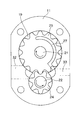
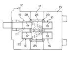
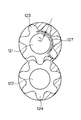
- FIG. 1 is a vertical cross-sectional view of the helical gear pump according to the embodiment of the present invention
- FIG. 2 is a cross-sectional view taken along the line AA.
- This helical gear pump is a hydraulic helical gear pump that uses hydraulic oil as the hydraulic fluid and sends this hydraulic oil by the action of a pair of helical gears 23 and 24.
- This helical gear pump is a pair of a casing composed of a body 11, a front cover 12 and a rear cover 13 and a pair of meshing with each other housed in a hole 19 formed in the body 11 called a spectacle hole or the like. It has helical gears 23 and 24, and bearing cases 25 and 26 as a pair of sliding contact members that sandwich the pair of helical gears 23 and 24 in the hole 19.
- the number of teeth of one helical gear 23 is larger than the number of teeth of the other helical gear 24.
- the number of teeth of the helical gear 23 is larger than the number of teeth of the helical gear 24 is synonymous with the fact that the tooth diameter of the helical gear 23 is larger than the tooth diameter of the helical gear 24. That is, when the helical gear 23 and the helical gear 24 are meshed with each other and both modules are the same, the larger the number of teeth, the larger the tooth diameter.
- the tooth diameter means, for example, the diameter of the base circle. In this case, in the helical gear 23 and the helical gear 24, the values obtained by dividing the base circle diameter by the number of teeth are the same.
- sliding contact means contacting in a relatively movable state. That is, the sliding contact member means a member that is in contact with the pair of helical gears 23 and 24 in a state where the pair of helical gears 23 and 24 are rotatable.
- the helical gear 23 is fixed to a drive shaft 21 that is rotated by driving a motor (not shown). Further, the helical gear 24 is fixed to the driven shaft 22. One end of the drive shaft 21 and the driven shaft 22 is pivotally supported in a bearing hole 17 formed in the bearing case 25 via a bush 15, and the other ends of the drive shaft 21 and the driven shaft 22 are formed in the bearing case 26. The bearing holes 18 are pivotally supported via bushes 16. The helical gears 23 and 24 rotate in the direction of the arrow shown in FIG. 2 in a state of being meshed with each other by the drive of the drive shaft 21.
- the helical gear 23 and the drive shaft 21, and the helical gear 24 and the driven shaft 22 are created by performing cutting, polishing, quenching, etc. on a single metal member.
- the helical gear 23 and the drive shaft 21 are integrated, and the helical gear 24 and the driven shaft 22 are integrated.
- the helical gear region of those members created as a unit is referred to as a helical gear 23 or a helical gear 24, and the shaft region is referred to as a drive shaft 21 or a driven shaft 22. There is.
- a suction passage 32 for supplying hydraulic oil to the hole 19 is formed on the low pressure region side where the teeth of the pair of helical gears 23 and 24 in the hole 19 formed in the body 11 gradually separate from each other. .. Further, a discharge passage 33 for discharging hydraulic oil from the hole 19 is formed on the high-pressure region side where the teeth of the pair of helical gears 23 and 24 in the hole 19 formed in the body 11 gradually mesh with each other. ing. In addition, either one or both of the suction path 32 and the discharge passage 33 are formed in the X direction (the direction perpendicular to the paper surface in FIG. 2) which is the axial direction of the drive shaft 21 and the driven shaft 22. May be good.
- a high-pressure hydraulic oil groove 27 communicating with a high-pressure region of the hydraulic fluid in the casing composed of the body 11, the front cover 12, and the rear cover 13 is formed in the outer region of the above.
- the high-pressure hydraulic oil groove 27 on the back side of the helical gear 23 is shown by a solid line.
- the helical gear 23 is pressed against the bearing case 26 with a large force, so that the bearing case 26 on the rear cover 13 side is pressed against the bearing case 26.
- a high-pressure hydraulic oil groove 27 communicating with a high-pressure region of the hydraulic fluid in the casing composed of the body 11, the front cover 12 and the rear cover 13 is formed, and the high-pressure hydraulic oil groove 27 is directed toward the side surface of the helical gear 23. It uses a configuration that supplies high-pressure hydraulic oil.
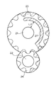
- FIG. 3 is an enlarged view showing the arrangement relationship between the helical gear 23 and the drive shaft 21 and the high-pressure hydraulic oil groove 27 formed in the outer region of the drive shaft 21 in the bearing case 26. Also in this figure, the high-pressure hydraulic oil groove 27 on the back side of the helical gear 23 is shown by a solid line.
- the region on the side surface of the pair of helical gears 23 and 24 on the side where the pair of helical gears 23 and 24 start meshing is a high pressure region.
- the outer peripheral regions of the drive shaft 21 and the driven shaft 22 on the side surfaces of the pair of helical gears 23 and 24 are low pressure regions. These high-pressure regions and low-pressure regions are sealed by a tooth bottom seal region of a pair of helical gears 23 and 24.
- a high-pressure hydraulic oil groove 27 is formed in the tooth bottom seal region of the helical gear 23 on the drive side.
- the helical gear 23 on the drive side has more teeth than the helical gear 24 on the driven side.
- the modules of the helical gear 23 on the driving side and the helical gear 24 on the driven side are equally meshed with each other.
- the tooth bottom seal region of the helical gear 23 on the drive side (the region between the tooth bottom circle of the helical gear 23 on the drive side and the bearing hole 18 of the drive shaft 21) is the conventional region shown in FIG. This is an extremely large area compared to helical gear pumps.
- the distance L2 (seal length) between the high-pressure region formed by the high-pressure hydraulic oil groove 27 and the low-pressure region formed by the outer peripheral portion of the drive shaft 21 is increased. It becomes possible to set. This makes it possible to suppress the leakage flow rate of the hydraulic oil from the high pressure region to the low pressure region on the side surfaces of the pair of helical gears 23 and 24. Further, this makes it possible to set a large oil groove area of the high-pressure hydraulic oil groove 27, and it is easy to cancel the force of the helical gear 23 on the drive side pressed against the bearing case 26 by the pressure of the hydraulic oil. It becomes.
- the force acting on the pair of helical gears 23 and 24 in the helical gear pump in the thrust direction is the force in the thrust direction due to the meshing torque transmission of the pair of helical gears 23 and 24.
- the force in the thrust direction due to the action of the hydraulic oil sent by the pair of helical gears 23 and 24 is roughly classified.
- the force in the thrust direction due to the meshing torque transmission does not depend on the number of teeth of the helical gear 23 on the drive side. Therefore, the increase in the thrust direction force due to the increase in the number of teeth of the helical gear 23 on the drive side is only due to the increase in the pressure receiving area of the hydraulic oil, and the increase in the thrust direction force is due to the high pressure hydraulic oil groove. By increasing the oil groove area of 27, it becomes possible to sufficiently cope with it.
- the number of teeth of the helical gear 23 on the driving side is larger than the number of teeth of the helical gear 24 on the driven side.
- the tooth bottom seal region of the helical gear 23 on the drive side can be made large, and the leakage flow rate of hydraulic oil can be suppressed.
- the number of teeth of the helical gear 23 on the drive side is increased, and the number of teeth of the helical gear 24 on the driven side is the same as the conventional one. It is possible to prevent an increase in the force in the thrust direction due to the meshing torque transmission of the helical gear 24, and it is possible to prevent the entire device from becoming excessively large.
- the high-pressure hydraulic oil groove 27 is formed in the outer region of the drive shaft 21 in the bearing case 26 on the rear cover 13 side of the pair of bearing cases 25 and 26, but the driven shaft 22 A high pressure hydraulic groove may also be formed in the outer region.
- FIG. 4 is a vertical sectional view of a helical gear pump according to another embodiment of the present invention.
- the same members as those in the embodiments shown in FIGS. 1 to 3 are designated by the same reference numerals, and detailed description thereof will be omitted.
- the bearing case 25 for accommodating the bush 15 and the bearing case for accommodating the bush 16 are used as a pair of sliding contact members for sandwiching the external gear pair including the helical gear 23 and the helical gear 24 from both sides. I am using 26. Then, a high-pressure hydraulic oil groove 27 communicating with a high-pressure region of the hydraulic fluid in the casing composed of the body 11, the front cover 12, and the rear cover 13 is formed in the bearing case 26 on the rear cover 13 side, and the high-pressure hydraulic oil groove 27 is formed. A configuration is adopted in which high-pressure hydraulic oil is supplied toward the side surface of the helical gear 23.
- a pair of side plates (sides) are used as a pair of sliding contact members that sandwich an external gear pair composed of the helical gear 23 and the helical gear 24 from both sides. Plates) 28 and 29 are used.
- a high-pressure hydraulic oil groove 27 similar to that shown in FIGS. 2 and 3 is formed on the side plate 29 on the rear cover 13 side to communicate with the high-pressure region of the hydraulic fluid in the casing composed of the body 11, the front cover 12, and the rear cover 13.
- a configuration is adopted in which high-pressure hydraulic oil is supplied from the high-pressure hydraulic oil groove 27 toward the side surface of the helical gear 23.
- one end of the drive shaft 21 and the driven shaft 22 is pivotally supported in a bearing hole 17 formed in the front cover 12 via a bush 15.
- the other ends of the 21 and the driven shaft 22 are pivotally supported in the bearing holes 18 formed in the rear cover 13 via the bush 16.
- a pair of bearing cases 25, 26 or a pair of side plates 28, 29 are used as sliding contact members.
- the pair of bearing cases 25, 26 or the pair of side plates 28, 29 may be omitted, and the front cover 12 and the rear cover 13 may be used as sliding contact members.
- the rear cover 13 is formed with the same high-pressure hydraulic oil groove 27 as in FIGS. 2 and 3 that communicates with the high-pressure region of the hydraulic fluid in the casing composed of the body 11, the front cover 12, and the rear cover 13.
- hydraulic oil leaks from the side surface region of the circumscribed gear pair consisting of the helical gear 23 and the helical gear 24. It has the advantage that it can be made smaller and the durability of the pump can be improved.
- one of the bearing case 25, the side plate 28, and the front cover 12 is used on one side surface of the circumscribed gear pair composed of the helical gear 23 and the helical gear 24, and the bearing is used on the other side surface.
- a case 25, a side plate 28, and a front cover 12 that are not used on one side surface they may be mixed and used.
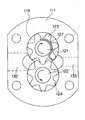
- FIG. 5 is a vertical cross-sectional view of the helical gear pump according to still another embodiment of the present invention
- FIG. 6 is a cross-sectional view taken along the line AA.
- FIG. 7 is an enlarged view showing the arrangement relationship between the helical gear 23 and the drive shaft 21 and the high-pressure hydraulic oil groove 27 formed in the outer region of the drive shaft 21 in the bearing case 26.
- the high-pressure hydraulic oil groove 27 on the back side of the helical gear 23 is shown by a solid line.
- the same members as those in the embodiments shown in FIGS. 1 to 3 are designated by the same reference numerals, and detailed description thereof will be omitted.
- the drive side has the number of teeth of the helical gear 23 larger than the number of teeth of the driven side helical gear 24, so that the drive side has the tooth bottom circle of the helical gear 23 and the drive shaft 21.
- the distance between the bearing hole 18 and the bearing hole 18 on the driven side is larger than the distance between the tooth bottom circle of the helical gear 24 and the bearing hole 18 of the driven shaft 22.
- the drive side is the bearing on the side where the helical gear 23 is pressed.
- the drive side drives the distance between the tooth bottom circle of the helical gear 23 and the bearing hole 18 of the drive shaft region 21a.
- the side is configured to be larger than the distance between the tooth bottom circle of the helical gear 24 and the bearing hole 18 of the driven shaft 22.
- the region on the side surface of the pair of helical gears 23 and 24 on the side where the pair of helical gears 23 and 24 start meshing. Is in the high pressure region.
- the outer peripheral regions of the drive shaft 21 and the driven shaft 22 on the side surfaces of the pair of helical gears 23 and 24 are low pressure regions. These high-pressure regions and low-pressure regions are sealed by a tooth bottom seal region of a pair of helical gears 23 and 24.
- a high-pressure hydraulic oil groove 27 is formed in the tooth bottom seal region of the helical gear 23 on the drive side.
- the outer diameter of the drive shaft region 21a penetrating the bearing case 26 on the side where the helical gear 23 is pressed is smaller than the outer diameter of the driven shaft 22. Therefore, the distance between the tooth bottom circle of the helical gear 23 and the bearing hole 18 of the drive shaft region 21a on the drive side is the distance between the tooth bottom circle of the helical gear 24 and the bearing hole 18 of the driven shaft 22 on the driven side. Can be larger.
- the tooth bottom seal region of the helical gear 23 on the drive side (the region between the tooth bottom circle of the helical gear 23 on the drive side and the bearing hole 18 of the drive shaft region 21a) is shown in FIG. This is an extremely large area compared to conventional helical gear pumps.
- the distance L3 (seal length) between the high-pressure region formed by the high-pressure hydraulic oil groove 27 and the low-pressure region formed by the outer peripheral portion of the drive shaft 21 is increased. It becomes possible to set. This makes it possible to suppress the leakage flow rate of the hydraulic oil from the high pressure region to the low pressure region on the side surfaces of the pair of helical gears 23 and 24.
- the outer diameter of the region 21a of the drive shaft 21 that penetrates the bearing case 26 on the side where the helical gear 23 is pressed is outside the driven shaft 22.
- the outer diameter of the drive shaft 21 may be smaller than the outer diameter of the driven shaft 22 in the entire area.
- high-pressure hydraulic oil is introduced from the discharge passage 33, thereby extracting rotational torque from the drive shaft 21 to drive an external load and constant pressure. It can also function as a helical gear motor that acts as a motor to discharge the hydraulic oil from the suction passage 32. That is, the helical gear pump in each of the above-described embodiments is also a helical gear motor.
- the hydraulic fluid is used as the hydraulic fluid, but a hydraulic fluid other than the hydraulic fluid such as other liquids, fluids or semi-fluids may be used.
Abstract
A helical gear pump comprises: a casing that is constituted by a body (11), a front cover (12), and a rear cover (13); a pair of helical gears (23) and (24) that is accommodated inside a hole formed in the body (11) and meshes with each other; and a pair of bearing cases (25) and (26) that sandwich the helical gears (23) and (24) therebetween inside the hole. Of the helical gears (23) and (24), the helical gear (23) on a driving side has gears greater in number than the helical gear (24) on a driven side.
Description
この発明は、各種の機器における油圧源として使用される油圧歯車ポンプ等の歯車ポンプまたはモータに関し、特に、互いに噛み合う駆動側はすば歯車および従動側はすば歯車からなる外接歯車対を使用したはすば歯車ポンプまたはモータに関する。
The present invention relates to gear pumps or motors such as hydraulic gear pumps used as hydraulic sources in various devices, and in particular uses external gear pairs consisting of helical gears on the driving side and helical gears on the driven side that mesh with each other. For helical gear pumps or motors.
歯車ポンプは、ボディに形成された孔部に対して互いに噛合した状態で収納される一対の平歯車と、これらの平歯車を固定する駆動軸および従動軸と、これらの平歯車の側面に摺接する一対のサイドプレート等の摺接部材と、これらの平歯車が漸次離反する低圧領域に配設され孔部に作動液としての作動油を供給するための吸込通路と、平歯車が漸次噛合する高圧領域に配設され孔部から作動油を排出するための吐出通路とを備えている。また、平歯車にかえ、閉じ込みのない連続的な歯当たりと小さな脈動による静音性を特徴とするはすば歯車を用いたはすば歯車ポンプも提案されている。
The gear pump slides on a pair of spur gears that are housed in mesh with each other through holes formed in the body, a drive shaft and a driven shaft that fix these spur gears, and a side surface of these spur gears. The spur gear gradually meshes with a pair of sliding contact members such as side plates that are in contact with each other, and a suction passage for supplying hydraulic oil as a hydraulic fluid to the hole portion where these spur gears are arranged in a low pressure region where they gradually separate. It is arranged in a high pressure region and is provided with a discharge passage for discharging hydraulic oil from a hole. In addition, a helical gear pump using a helical gear, which is characterized by continuous tooth contact without confinement and quietness due to small pulsation, has been proposed instead of the spur gear.
このようなはすば歯車ポンプにおいては、はすば歯車の噛み合いによるスラスト方向の力と、歯車表面に分布する油圧によるスラスト方向の力により、特に、駆動側のはすば歯車においてスラスト方向に大きな力が生ずる。このようなスラスト方向の力に対応するため、はすば歯車を支持する軸の端面に軸をスラスト方向の力が生ずる方向と逆方向に押圧するための液圧室を有する液圧機構を設け、この液圧室に高圧側の作動油を導くことにより、この液圧機構により軸を介してはすば歯車をスラスト力の発生方向と逆方向に押圧する歯車ポンプまたはモータが提案されている(特許文献1参照)。
In such a helical gear pump, the force in the thrust direction due to the meshing of the helical gear and the force in the thrust direction due to the hydraulic pressure distributed on the gear surface cause the helical gear on the drive side to be in the thrust direction in particular. Great force is generated. In order to deal with such a force in the thrust direction, a hydraulic mechanism having a hydraulic chamber for pressing the shaft in the direction opposite to the direction in which the force in the thrust direction is generated is provided on the end surface of the shaft supporting the helical gear. , A gear pump or motor has been proposed in which the hydraulic oil on the high pressure side is guided to this hydraulic chamber to press the helical gear through the shaft in the direction opposite to the direction in which the thrust force is generated by this hydraulic mechanism. (See Patent Document 1).
しかしながら、特許文献1に記載されたような液圧機構を設けるためには、より多くの部品が必要となり、また、装置構成が複雑となる。
However, in order to provide the hydraulic pressure mechanism as described in Patent Document 1, more parts are required and the device configuration becomes complicated.
この発明は上記課題を解決するためになされたものであり、簡易な構成でありながら、駆動側はすば歯車が摺接部材に押しつけられる力の大きさを小さくすることが可能なはすば歯車ポンプまたはモータを提供することを目的とする。
The present invention has been made in order to solve the above problems, and although it has a simple structure, the drive side can reduce the magnitude of the force with which the helical gear is pressed against the sliding contact member. It is intended to provide a gear pump or motor.
請求項1に記載の発明は、互いに噛み合う駆動側はすば歯車および従動側はすば歯車からなる外接歯車対と、前記駆動側はすば歯車に連結された駆動軸の軸受孔と前記従動側はすば歯車に連結された従動軸の軸受孔とが形成され、前記外接歯車対を両側から挟む一対の摺接部材と、前記外接歯車対および前記一対の摺接部材を収納するケーシングと、前記一対の摺接部材のうち、前記駆動側はすば歯車が押圧される側の摺接部材における前記駆動側はすば歯車との当接領域に形成され、前記ケーシング内の作動液の高圧領域と連通する高圧作動液溝と、を備えたはすば歯車ポンプまたはモータであって、前記駆動側はすば歯車の歯底円と前記駆動軸の軸受孔との距離を、前記従動側はすば歯車の歯底円と前記従動軸の軸受孔との距離より大きくした。
The invention according to claim 1 is an external gear pair composed of a helical gear on the drive side and a helical gear on the driven side that mesh with each other, and a bearing hole of a drive shaft connected to the helical gear on the drive side and the driven gear. On the side, a bearing hole of a driven shaft connected to a helical gear is formed, and a pair of sliding contact members sandwiching the external gear pair from both sides, and a casing for accommodating the external gear pair and the pair of sliding contact members. Of the pair of sliding contact members, the driving side is formed in the contact region with the helical gear in the sliding contact member on the side where the helical gear is pressed, and the working liquid in the casing is formed. A helical gear pump or motor including a high-pressure working fluid groove that communicates with a high-pressure region, and the drive side drives the distance between the tooth bottom circle of the helical gear and the bearing hole of the drive shaft. The side is made larger than the distance between the tooth bottom circle of the helical gear and the bearing hole of the driven shaft.
請求項2に記載の発明は、請求項1に記載の発明において、前記駆動側はすば歯車の歯数を、前記従動側はすば歯車の歯数より多くした。
The invention according to claim 2 has the number of teeth of the helical gear on the driving side larger than the number of teeth of the helical gear on the driven side in the invention according to claim 1.
請求項3に記載の発明は、請求項1に記載の発明において、前記駆動軸における前記一対の摺接部材のうち前記駆動側はすば歯車が押圧される側の摺接部材を貫通する領域の外径を前記従動軸の外径より小さくした。
The invention according to claim 3 is a region in which the drive side of the pair of sliding contact members on the drive shaft penetrates the sliding contact member on the side where the helical gear is pressed in the invention according to claim 1. The outer diameter of the driven shaft was made smaller than the outer diameter of the driven shaft.
請求項4に記載の発明は、請求項1から請求項3のいずれかに記載の発明において、前記摺接部材は、ベアリングケースまたは側板である。
The invention according to claim 4 is the invention according to any one of claims 1 to 3, wherein the sliding contact member is a bearing case or a side plate.
請求項1から請求項4に記載の発明によれば、摺接部材に形成された高圧作動液溝内の作動油の作用により、駆動側のはすば歯車をスラスト方向の力が生ずる方向と逆方向に押圧することができる。そして、駆動側はすば歯車の歯底円と駆動軸の軸受孔との距離を、従動側はすば歯車の歯底円と従動軸の軸受孔との距離より大きくすることにより、作動液のもれ流量を抑制することが可能となる。
According to the inventions of claims 1 to 4, the direction in which a force is generated in the thrust direction of the helical gear on the drive side by the action of the hydraulic oil in the high-pressure hydraulic fluid groove formed in the sliding contact member. It can be pressed in the opposite direction. Then, the drive side is made the distance between the tooth bottom circle of the helical gear and the bearing hole of the drive shaft larger than the distance between the tooth bottom circle of the helical gear and the bearing hole of the driven shaft. It is possible to suppress the leakage flow rate.
請求項2に記載の発明によれば、駆動側はすば歯車の歯数を従動側はすば歯車の歯数より多くすることにより、駆動側はすば歯車の歯底シール領域を大きくとることができ、作動液のもれ流量を抑制することが可能となる。この時、駆動側はすば歯車の歯数を多くし、従動側はすば歯車の歯数を従来同様とすることにより、駆動側はすば歯車と従動側はすば歯車の噛み合いトルク伝達によるスラスト方向の力の増加を防止できるとともに、装置全体が過度に大きくなることを防止することが可能となる。
According to the second aspect of the present invention, the drive side has a larger number of teeth of the helical gear than the number of teeth of the helical gear on the driven side, so that the drive side has a large tooth bottom seal region of the helical gear. This makes it possible to suppress the leakage flow rate of the hydraulic fluid. At this time, by increasing the number of teeth of the helical gear on the drive side and making the number of teeth of the helical gear on the driven side the same as before, the meshing torque transmission between the helical gear on the drive side and the helical gear on the driven side It is possible to prevent an increase in the force in the thrust direction due to the above, and also to prevent the entire device from becoming excessively large.
請求項3に記載の発明によれば、駆動軸における一対の摺接部材のうち駆動側はすば歯車が押圧される側の摺接部材を貫通する領域の外径を従動軸の外径より小さくすることにより、駆動側はすば歯車の歯底シール領域を大きくとることができ、作動液のもれ流量を抑制することが可能となる。
According to the third aspect of the present invention, the outer diameter of the region of the pair of sliding contact members on the drive shaft that penetrates the sliding contact member on the side where the helical gear is pressed is set from the outer diameter of the driven shaft. By making it smaller, the drive side can have a large tooth bottom seal region of the helical gear, and it is possible to suppress the leakage flow rate of the hydraulic fluid.
最初に、比較例として、駆動側のはすば歯車をスラスト方向の力が生ずる方向と逆方向に押圧するため、スラスト方向の力を受ける摺接部材における駆動側はすば歯車との当接領域に、ケーシング内の作動油の高圧領域と連通する高圧作動油溝を形成し、この高圧作動油溝内の作動油の作用により駆動側はすば歯車をスラスト方向の力が生ずる方向と逆方向に押圧するはすば歯車ポンプの構成について説明する。
First, as a comparative example, since the helical gear on the drive side is pressed in the direction opposite to the direction in which the force in the thrust direction is generated, the drive side in the sliding contact member that receives the force in the thrust direction comes into contact with the helical gear. A high-pressure hydraulic oil groove is formed in the region so as to communicate with the high-pressure region of the hydraulic oil in the casing, and the action of the hydraulic oil in the high-pressure hydraulic oil groove causes the helical gear on the drive side to be opposite to the direction in which the thrust direction force is generated. The configuration of the helical gear pump that presses in the direction will be described.
図8は、このような構成を有する比較例としてのはすば歯車ポンプの縦断面図であり、図9は、そのA-A断面矢視図である。
FIG. 8 is a vertical cross-sectional view of a helical gear pump as a comparative example having such a configuration, and FIG. 9 is a cross-sectional view taken along the line AA.
このはすば歯車ポンプは、作動油を一対のはすば歯車123、124の作用により送液するはすば歯車ポンプであり、ボディ111、フロントカバー112およびリアカバー113により構成されるケーシングと、ボディ111に形成された眼鏡孔等と呼称される孔部119内に収納された互いに噛合する一対のはすば歯車123、124と、孔部119内において一対のはすば歯車123、124を挟持する一対のベアリングケース125、126とを有する。
This helical gear pump is a helical gear pump that feeds hydraulic oil by the action of a pair of helical gears 123 and 124, and has a casing composed of a body 111, a front cover 112, and a rear cover 113. A pair of helical gears 123, 124 that mesh with each other and are housed in a hole 119 called a spectacle hole or the like formed in the body 111, and a pair of helical gears 123, 124 in the hole 119. It has a pair of bearing cases 125 and 126 to be sandwiched.
はすば歯車123は、図示しないモータの駆動により回転する駆動軸121に固定されている。また、はすば歯車124は、従動軸122に固定されている。駆動軸121および従動軸122の一端は、ベアリングケース125に形成された軸受孔117にブッシュ115を介して軸支されており、駆動軸121および従動軸122の他端は、ベアリングケース126に形成された軸受孔118にブッシュ116を介して軸支されている。はすば歯車123、124は、駆動軸121の駆動により、互いに噛合した状態で、図9に示す矢印方向に回転する。
The helical gear 123 is fixed to a drive shaft 121 that is rotated by driving a motor (not shown). Further, the helical gear 124 is fixed to the driven shaft 122. One end of the drive shaft 121 and the driven shaft 122 is pivotally supported by a bearing hole 117 formed in the bearing case 125 via a bush 115, and the other ends of the drive shaft 121 and the driven shaft 122 are formed in the bearing case 126. The bearing holes 118 are pivotally supported via bushes 116. The helical gears 123 and 124 are driven by the drive shaft 121 and rotate in the direction of the arrow shown in FIG. 9 in a state of being meshed with each other.
ボディ111に形成された孔部119における一対のはすば歯車123、124の歯が漸次離反する低圧領域側には、孔部119に作動油を供給するための吸込通路132が形成されている。また、ボディ111に形成された孔部119における一対のはすば歯車123、124の歯が漸次噛合する高圧領域側には、孔部119から作動油を排出するための吐出通路133が形成されている。
A suction passage 132 for supplying hydraulic oil to the hole 119 is formed on the low pressure region side where the teeth of the pair of helical gears 123 and 124 in the hole 119 formed in the body 111 gradually separate from each other. .. Further, a discharge passage 133 for discharging hydraulic oil from the hole 119 is formed on the high-pressure region side where the teeth of the pair of helical gears 123 and 124 in the hole 119 formed in the body 111 gradually mesh with each other. ing.
一対のはすば歯車123、124を挟持する一対のベアリングケース125、126のうち、リアカバー113側のベアリングケース126における駆動軸121の外側領域には、ボディ111、フロントカバー112およびリアカバー113により構成されるケーシング内の作動液の高圧領域と連通する高圧作動油溝127が形成されている。なお、図9においては、はすば歯車123の奥側にある高圧作動油溝127を実線で図示している。
Of the pair of bearing cases 125 and 126 that sandwich the pair of helical gears 123 and 124, the outer region of the drive shaft 121 in the bearing case 126 on the rear cover 113 side is composed of the body 111, the front cover 112 and the rear cover 113. A high-pressure hydraulic oil groove 127 communicating with the high-pressure region of the hydraulic fluid in the casing is formed. In FIG. 9, the high-pressure hydraulic oil groove 127 on the back side of the helical gear 123 is shown by a solid line.
図10は、外接歯車対をなす一対のはすば歯車123、124に作用するスラスト方向の力を示す説明図である。
FIG. 10 is an explanatory diagram showing a force in the thrust direction acting on the pair of helical gears 123 and 124 forming a pair of circumscribed gears.
この図に示すように、はすば歯車ポンプにおける一対のはすば歯車123、124に作用するスラスト方向の力は、一対のはすば歯車123、124の噛み合いトルク伝達によるスラスト方向の力101A、101Bと、一対のはすば歯車123、124により送液される作動油の作用によるスラスト方向の力102A、102Bとに大別される。そして、はすば歯車124においては、スラスト方向の力101Bと102Bとが逆方向を向くのに対し、はすば歯車123においては、スラスト方向の力101Aと102Aとが同一方向を向く。このため、はすば歯車123は、大きな力でベアリングケース126に押しつけられることになる。
As shown in this figure, the thrust direction force acting on the pair of helical gears 123 and 124 in the helical gear pump is the thrust direction force 101A due to the meshing torque transmission of the pair of helical gears 123 and 124. , 101B and forces 102A and 102B in the thrust direction due to the action of hydraulic oil sent by the pair of helical gears 123 and 124. In the helical gear 124, the forces 101B and 102B in the thrust direction face in opposite directions, whereas in the helical gear 123, the forces 101A and 102A in the thrust direction face in the same direction. Therefore, the helical gear 123 is pressed against the bearing case 126 with a large force.
このため、リアカバー113側のベアリングケース126における駆動軸121の外側領域に、ボディ111、フロントカバー112およびリアカバー113により構成されるケーシング内の作動液の高圧領域と連通する高圧作動油溝127を形成し、この高圧作動油溝127からはすば歯車123の側面に向けて高圧の作動油を供給し、これにより、はすば歯車123がベアリングケース126に対して大きな力で押しつけられることを防止している。
Therefore, a high-pressure hydraulic oil groove 127 communicating with the high-pressure region of the hydraulic fluid in the casing composed of the body 111, the front cover 112, and the rear cover 113 is formed in the outer region of the drive shaft 121 in the bearing case 126 on the rear cover 113 side. However, high-pressure hydraulic oil is supplied from the high-pressure hydraulic oil groove 127 toward the side surface of the helical gear 123, thereby preventing the helical gear 123 from being pressed against the bearing case 126 with a large force. doing.
図11は、ベアリングケース126における駆動軸121の外側領域に形成された高圧作動油溝127とはすば歯車123および駆動軸121との配置関係を示す拡大図である。なお、この図においても、はすば歯車123の奥側にある高圧作動油溝127を実線で図示している。
FIG. 11 is an enlarged view showing the arrangement relationship between the high-pressure hydraulic oil groove 127 formed in the outer region of the drive shaft 121 in the bearing case 126, the helical gear 123, and the drive shaft 121. Also in this figure, the high-pressure hydraulic oil groove 127 on the back side of the helical gear 123 is shown by a solid line.
図11においてハッチングを付したように、一対のはすば歯車123、124の側面における一対のはすば歯車123、124が噛合を開始する側の領域は高圧領域となっている。一方、一対のはすば歯車123、124の側面における駆動軸121および従動軸122の外周部の領域は低圧領域となっている。そして、これらの高圧領域と低圧領域とは、一対のはすば歯車123、124の歯底シール領域によりシールされている。
As shown by hatching in FIG. 11, the region on the side surface of the pair of helical gears 123 and 124 on the side where the pair of helical gears 123 and 124 start meshing is a high pressure region. On the other hand, the outer peripheral region of the drive shaft 121 and the driven shaft 122 on the side surfaces of the pair of helical gears 123 and 124 is a low pressure region. The high pressure region and the low pressure region are sealed by the tooth bottom seal region of the pair of helical gears 123 and 124.
この歯底シール領域は、駆動側のはすば歯車123の側面においては、駆動側はすば歯車123の歯底円と駆動軸121の軸受孔118との間の領域である。そして、この歯底シール領域に高圧領域と連通する高圧作動油溝127が形成されている。このため、高圧作動油溝127による高圧領域と駆動軸121の外周部による低圧領域との距離L1(シール長さ)が極めて小さくなる。これにより、一対のはすば歯車123、124の側面における高圧領域から低圧領域への作動油のもれ流量が大きくなり、作動油の送液性能が低下するという問題が生ずる。
This tooth bottom seal region is a region on the side surface of the helical gear 123 on the drive side between the tooth bottom circle of the helical gear 123 on the drive side and the bearing hole 118 of the drive shaft 121. A high-pressure hydraulic oil groove 127 communicating with the high-pressure region is formed in the tooth bottom seal region. Therefore, the distance L1 (seal length) between the high pressure region formed by the high pressure hydraulic oil groove 127 and the low pressure region formed by the outer peripheral portion of the drive shaft 121 becomes extremely small. As a result, the leakage flow rate of the hydraulic oil from the high pressure region to the low pressure region on the side surfaces of the pair of helical gears 123 and 124 becomes large, and there arises a problem that the liquid feeding performance of the hydraulic oil deteriorates.
次に、上述した比較例の問題を解消したはすば歯車ポンプの構成について説明する。図1は、この発明の実施形態に係るはすば歯車ポンプの縦断面図であり、図2は、そのA-A断面矢視図である。
Next, the configuration of the helical gear pump that solves the problem of the above-mentioned comparative example will be described. FIG. 1 is a vertical cross-sectional view of the helical gear pump according to the embodiment of the present invention, and FIG. 2 is a cross-sectional view taken along the line AA.
このはすば歯車ポンプは、作動液として作動油を使用し、この作動油を一対のはすば歯車23、24の作用により送液する油圧はすば歯車ポンプである。このはすば歯車ポンプは、ボディ11、フロントカバー12およびリアカバー13により構成されるケーシングと、ボディ11に形成された眼鏡孔等と呼称される孔部19内に収納された互いに噛合する一対のはすば歯車23、24と、孔部19内において一対のはすば歯車23、24を挟持する一対の摺接部材としてのベアリングケース25、26とを有する。一対のはすば歯車23、24のうち、一方のはすば歯車23の歯数は、他方のはすば歯車24の歯数より多くなっている。
This helical gear pump is a hydraulic helical gear pump that uses hydraulic oil as the hydraulic fluid and sends this hydraulic oil by the action of a pair of helical gears 23 and 24. This helical gear pump is a pair of a casing composed of a body 11, a front cover 12 and a rear cover 13 and a pair of meshing with each other housed in a hole 19 formed in the body 11 called a spectacle hole or the like. It has helical gears 23 and 24, and bearing cases 25 and 26 as a pair of sliding contact members that sandwich the pair of helical gears 23 and 24 in the hole 19. Of the pair of helical gears 23 and 24, the number of teeth of one helical gear 23 is larger than the number of teeth of the other helical gear 24.
なお、はすば歯車23の歯数がはすば歯車24の歯数より多いとは、はすば歯車23の歯径がはすば歯車24の歯径より大きいと同義である。すなわち、はすば歯車23とはすば歯車24とが噛合しており両者のモジュールが同一である場合には、歯数が多くなれば歯径も大きくなる。この歯径とは、はすば歯車23およびはすば歯車24がインボリュート歯車である場合には、例えば、基礎円直径を意味する。この場合には、はすば歯車23およびはすば歯車24において、基礎円直径を歯数で除算した値は、同一の値となる。
Note that the number of teeth of the helical gear 23 is larger than the number of teeth of the helical gear 24 is synonymous with the fact that the tooth diameter of the helical gear 23 is larger than the tooth diameter of the helical gear 24. That is, when the helical gear 23 and the helical gear 24 are meshed with each other and both modules are the same, the larger the number of teeth, the larger the tooth diameter. When the helical gear 23 and the helical gear 24 are involute gears, the tooth diameter means, for example, the diameter of the base circle. In this case, in the helical gear 23 and the helical gear 24, the values obtained by dividing the base circle diameter by the number of teeth are the same.
また、摺接とは相対的に移動可能な状態で接することを意味する。すなわち、摺接部材とは、一対のはすば歯車23、24を回転可能とした状態で一対のはすば歯車23、24と接する部材を意味する。
Also, sliding contact means contacting in a relatively movable state. That is, the sliding contact member means a member that is in contact with the pair of helical gears 23 and 24 in a state where the pair of helical gears 23 and 24 are rotatable.
はすば歯車23は、図示しないモータの駆動により回転する駆動軸21に固定されている。また、はすば歯車24は、従動軸22に固定されている。駆動軸21および従動軸22の一端は、ベアリングケース25に形成された軸受孔17にブッシュ15を介して軸支されており、駆動軸21および従動軸22の他端は、ベアリングケース26に形成された軸受孔18にブッシュ16を介して軸支されている。はすば歯車23、24は、駆動軸21の駆動により、互いに噛合した状態で、図2に示す矢印方向に回転する。
The helical gear 23 is fixed to a drive shaft 21 that is rotated by driving a motor (not shown). Further, the helical gear 24 is fixed to the driven shaft 22. One end of the drive shaft 21 and the driven shaft 22 is pivotally supported in a bearing hole 17 formed in the bearing case 25 via a bush 15, and the other ends of the drive shaft 21 and the driven shaft 22 are formed in the bearing case 26. The bearing holes 18 are pivotally supported via bushes 16. The helical gears 23 and 24 rotate in the direction of the arrow shown in FIG. 2 in a state of being meshed with each other by the drive of the drive shaft 21.
なお、はすば歯車23と駆動軸21、また、はすば歯車24と従動軸22とは、単一の金属部材に対して切削加工、研磨加工、焼入れ加工等を実行することにより作成されるものであり、はすば歯車23と駆動軸21、また、はすば歯車24と従動軸22とは一体のものである。この明細書においては、一体として作成されるそれらの部材におけるはすば歯車領域をはすば歯車23またははすば歯車24と呼称し、軸領域を駆動軸21または従動軸22と呼称している。
The helical gear 23 and the drive shaft 21, and the helical gear 24 and the driven shaft 22 are created by performing cutting, polishing, quenching, etc. on a single metal member. The helical gear 23 and the drive shaft 21 are integrated, and the helical gear 24 and the driven shaft 22 are integrated. In this specification, the helical gear region of those members created as a unit is referred to as a helical gear 23 or a helical gear 24, and the shaft region is referred to as a drive shaft 21 or a driven shaft 22. There is.
ボディ11に形成された孔部19における一対のはすば歯車23、24の歯が漸次離反する低圧領域側には、孔部19に作動油を供給するための吸込通路32が形成されている。また、ボディ11に形成された孔部19における一対のはすば歯車23、24の歯が漸次噛合する高圧領域側には、孔部19から作動油を排出するための吐出通路33が形成されている。なお、吸込経路32および吐出通路33のいずれか一方、または、両方を、駆動軸21および従動軸22の軸心方向であるX方向(図2における紙面に垂直な方向)に向けて形成してもよい。
A suction passage 32 for supplying hydraulic oil to the hole 19 is formed on the low pressure region side where the teeth of the pair of helical gears 23 and 24 in the hole 19 formed in the body 11 gradually separate from each other. .. Further, a discharge passage 33 for discharging hydraulic oil from the hole 19 is formed on the high-pressure region side where the teeth of the pair of helical gears 23 and 24 in the hole 19 formed in the body 11 gradually mesh with each other. ing. In addition, either one or both of the suction path 32 and the discharge passage 33 are formed in the X direction (the direction perpendicular to the paper surface in FIG. 2) which is the axial direction of the drive shaft 21 and the driven shaft 22. May be good.
一対のはすば歯車23、24を挟持する一対のベアリングケース25、26のうち、リアカバー13側、すなわち、駆動側のはすば歯車23が押圧される側となるベアリングケース26における駆動軸21の外側領域には、ボディ11、フロントカバー12およびリアカバー13により構成されるケーシング内の作動液の高圧領域と連通する高圧作動油溝27が形成されている。なお、図2においては、はすば歯車23の奥側にある高圧作動油溝27を実線で図示している。
Of the pair of bearing cases 25 and 26 that sandwich the pair of helical gears 23 and 24, the drive shaft 21 in the bearing case 26 on the rear cover 13 side, that is, the side on which the helical gear 23 on the drive side is pressed. A high-pressure hydraulic oil groove 27 communicating with a high-pressure region of the hydraulic fluid in the casing composed of the body 11, the front cover 12, and the rear cover 13 is formed in the outer region of the above. In FIG. 2, the high-pressure hydraulic oil groove 27 on the back side of the helical gear 23 is shown by a solid line.
このはすば歯車ポンプにおいては、図10に示す従来のはすば歯車ポンプと同様、はすば歯車23が大きな力でベアリングケース26に押しつけられることから、リアカバー13側のベアリングケース26に、ボディ11、フロントカバー12およびリアカバー13により構成されるケーシング内の作動液の高圧領域と連通する高圧作動油溝27を形成し、この高圧作動油溝27からはすば歯車23の側面に向けて高圧の作動油を供給する構成を採用している。
In this helical gear pump, as in the conventional helical gear pump shown in FIG. 10, the helical gear 23 is pressed against the bearing case 26 with a large force, so that the bearing case 26 on the rear cover 13 side is pressed against the bearing case 26. A high-pressure hydraulic oil groove 27 communicating with a high-pressure region of the hydraulic fluid in the casing composed of the body 11, the front cover 12 and the rear cover 13 is formed, and the high-pressure hydraulic oil groove 27 is directed toward the side surface of the helical gear 23. It uses a configuration that supplies high-pressure hydraulic oil.
図3は、ベアリングケース26における駆動軸21の外側領域に形成された高圧作動油溝27とはすば歯車23および駆動軸21との配置関係を示す拡大図である。なお、この図においても、はすば歯車23の奥側にある高圧作動油溝27を実線で図示している。
FIG. 3 is an enlarged view showing the arrangement relationship between the helical gear 23 and the drive shaft 21 and the high-pressure hydraulic oil groove 27 formed in the outer region of the drive shaft 21 in the bearing case 26. Also in this figure, the high-pressure hydraulic oil groove 27 on the back side of the helical gear 23 is shown by a solid line.
図3においてハッチングを付したように、一対のはすば歯車23、24の側面における一対のはすば歯車23、24が噛合を開始する側の領域は高圧領域となっている。一方、一対のはすば歯車23、24の側面における駆動軸21および従動軸22の外周部の領域は低圧領域となっている。これらの高圧領域と低圧領域とは、一対のはすば歯車23、24の歯底シール領域によりシールされている。そして、駆動側のはすば歯車23の歯底シール領域に高圧作動油溝27が形成されている。
As shown by hatching in FIG. 3, the region on the side surface of the pair of helical gears 23 and 24 on the side where the pair of helical gears 23 and 24 start meshing is a high pressure region. On the other hand, the outer peripheral regions of the drive shaft 21 and the driven shaft 22 on the side surfaces of the pair of helical gears 23 and 24 are low pressure regions. These high-pressure regions and low-pressure regions are sealed by a tooth bottom seal region of a pair of helical gears 23 and 24. A high-pressure hydraulic oil groove 27 is formed in the tooth bottom seal region of the helical gear 23 on the drive side.
ここで、駆動側のはすば歯車23は、従動側のはすば歯車24より歯数が多い。そして、駆動側のはすば歯車23と従動側のはすば歯車24とは、モジュールが等しく互いに噛み合っている。これにより、駆動側のはすば歯車23の歯底シール領域(駆動側はすば歯車23の歯底円と駆動軸21の軸受孔18との間の領域)は、図11に示す従来のはすば歯車ポンプと比較して極めて大きな領域となっている。このため、この歯底シール領域に高圧作動油溝27を形成した場合においても、高圧作動油溝27による高圧領域と駆動軸21の外周部による低圧領域との距離L2(シール長さ)を大きく設定することが可能となる。これにより、一対のはすば歯車23、24の側面における高圧領域から低圧領域への作動油のもれ流量を抑制することが可能となる。また、これにより、高圧作動油溝27の油溝面積を大きく設定することも可能となり、駆動側のはすば歯車23がベアリングケース26に押しつけられる力を作動油の圧力によりキャンセルすることが容易となる。
Here, the helical gear 23 on the drive side has more teeth than the helical gear 24 on the driven side. The modules of the helical gear 23 on the driving side and the helical gear 24 on the driven side are equally meshed with each other. As a result, the tooth bottom seal region of the helical gear 23 on the drive side (the region between the tooth bottom circle of the helical gear 23 on the drive side and the bearing hole 18 of the drive shaft 21) is the conventional region shown in FIG. This is an extremely large area compared to helical gear pumps. Therefore, even when the high-pressure hydraulic oil groove 27 is formed in the tooth bottom seal region, the distance L2 (seal length) between the high-pressure region formed by the high-pressure hydraulic oil groove 27 and the low-pressure region formed by the outer peripheral portion of the drive shaft 21 is increased. It becomes possible to set. This makes it possible to suppress the leakage flow rate of the hydraulic oil from the high pressure region to the low pressure region on the side surfaces of the pair of helical gears 23 and 24. Further, this makes it possible to set a large oil groove area of the high-pressure hydraulic oil groove 27, and it is easy to cancel the force of the helical gear 23 on the drive side pressed against the bearing case 26 by the pressure of the hydraulic oil. It becomes.
なお、上述したように、はすば歯車ポンプにおける一対のはすば歯車23、24に作用するスラスト方向の力は、一対のはすば歯車23、24の噛み合いトルク伝達によるスラスト方向の力と、一対のはすば歯車23、24により送液される作動油の作用によるスラスト方向の力とに大別される。そして、噛み合いトルク伝達によるスラスト方向の力は、駆動側のはすば歯車23の歯数には依存しない。このため、駆動側のはすば歯車23の歯数の増加によるスラスト方向の力の増加は、作動油の受圧面積の増大によるものだけであり、そのスラスト方向の力の増加は高圧作動油溝27の油溝面積を増加させることにより十分対応可能なものとなる。
As described above, the force acting on the pair of helical gears 23 and 24 in the helical gear pump in the thrust direction is the force in the thrust direction due to the meshing torque transmission of the pair of helical gears 23 and 24. , The force in the thrust direction due to the action of the hydraulic oil sent by the pair of helical gears 23 and 24 is roughly classified. The force in the thrust direction due to the meshing torque transmission does not depend on the number of teeth of the helical gear 23 on the drive side. Therefore, the increase in the thrust direction force due to the increase in the number of teeth of the helical gear 23 on the drive side is only due to the increase in the pressure receiving area of the hydraulic oil, and the increase in the thrust direction force is due to the high pressure hydraulic oil groove. By increasing the oil groove area of 27, it becomes possible to sufficiently cope with it.
以上のように、この発明の実施形態に係るはすば歯車ポンプによれば、駆動側のはすば歯車23の歯数を従動側のはすば歯車24の歯数より多くすることにより、駆動側のはすば歯車23の歯底シール領域を大きくとることができ、作動油のもれ流量を抑制することが可能となる。この時、駆動側のはすば歯車23の歯数を多くし、従動側のはすば歯車24の歯数を従来同様とすることにより、駆動側のはすば歯車23と従動側のはすば歯車24の噛み合いトルク伝達によるスラスト方向の力の増加を防止できるとともに、装置全体が過度に大きくなることを防止することが可能となる。
As described above, according to the helical gear pump according to the embodiment of the present invention, the number of teeth of the helical gear 23 on the driving side is larger than the number of teeth of the helical gear 24 on the driven side. The tooth bottom seal region of the helical gear 23 on the drive side can be made large, and the leakage flow rate of hydraulic oil can be suppressed. At this time, the number of teeth of the helical gear 23 on the drive side is increased, and the number of teeth of the helical gear 24 on the driven side is the same as the conventional one. It is possible to prevent an increase in the force in the thrust direction due to the meshing torque transmission of the helical gear 24, and it is possible to prevent the entire device from becoming excessively large.
なお、上述した実施形態においては、一対のベアリングケース25、26のうち、リアカバー13側のベアリングケース26における駆動軸21の外側領域に高圧作動油溝27を形成しているが、従動軸22の外側領域にも高圧作動油溝を形成してもよい。
In the above-described embodiment, the high-pressure hydraulic oil groove 27 is formed in the outer region of the drive shaft 21 in the bearing case 26 on the rear cover 13 side of the pair of bearing cases 25 and 26, but the driven shaft 22 A high pressure hydraulic groove may also be formed in the outer region.
次に、この発明の他の実施形態について説明する。図4は、この発明の他の実施形態に係るはすば歯車ポンプの縦断面図である。なお、図1から図3に示す実施形態と同様の部材については、同一の符号を付して詳細な説明を省略する。
Next, other embodiments of the present invention will be described. FIG. 4 is a vertical sectional view of a helical gear pump according to another embodiment of the present invention. The same members as those in the embodiments shown in FIGS. 1 to 3 are designated by the same reference numerals, and detailed description thereof will be omitted.
上述した実施形態においては、はすば歯車23およびはすば歯車24からなる外接歯車対を両側から挟む一対の摺接部材として、ブッシュ15を収納するベアリングケース25およびブッシュ16を収納するベアリングケース26を使用している。そして、リアカバー13側のベアリングケース26に、ボディ11、フロントカバー12およびリアカバー13により構成されるケーシング内の作動液の高圧領域と連通する高圧作動油溝27を形成し、この高圧作動油溝27からはすば歯車23の側面に向けて高圧の作動油を供給する構成を採用している。
In the above-described embodiment, the bearing case 25 for accommodating the bush 15 and the bearing case for accommodating the bush 16 are used as a pair of sliding contact members for sandwiching the external gear pair including the helical gear 23 and the helical gear 24 from both sides. I am using 26. Then, a high-pressure hydraulic oil groove 27 communicating with a high-pressure region of the hydraulic fluid in the casing composed of the body 11, the front cover 12, and the rear cover 13 is formed in the bearing case 26 on the rear cover 13 side, and the high-pressure hydraulic oil groove 27 is formed. A configuration is adopted in which high-pressure hydraulic oil is supplied toward the side surface of the helical gear 23.
これに対して、この実施形態に係るはすば歯車ポンプにおいては、はすば歯車23およびはすば歯車24からなる外接歯車対を両側から挟む一対の摺接部材として、一対の側板(サイドプレート)28、29を使用している。そして、リアカバー13側の側板29に、ボディ11、フロントカバー12およびリアカバー13により構成されるケーシング内の作動液の高圧領域と連通する図2および図3と同様の高圧作動油溝27を形成し、この高圧作動油溝27からはすば歯車23の側面に向けて高圧の作動油を供給する構成を採用している。
On the other hand, in the helical gear pump according to this embodiment, a pair of side plates (sides) are used as a pair of sliding contact members that sandwich an external gear pair composed of the helical gear 23 and the helical gear 24 from both sides. Plates) 28 and 29 are used. Then, a high-pressure hydraulic oil groove 27 similar to that shown in FIGS. 2 and 3 is formed on the side plate 29 on the rear cover 13 side to communicate with the high-pressure region of the hydraulic fluid in the casing composed of the body 11, the front cover 12, and the rear cover 13. A configuration is adopted in which high-pressure hydraulic oil is supplied from the high-pressure hydraulic oil groove 27 toward the side surface of the helical gear 23.
なお、一対の側板28、29を使用する場合においては、駆動軸21および従動軸22の一端は、フロントカバー12に形成された軸受孔17にブッシュ15を介して軸支されており、駆動軸21および従動軸22の他端は、リアカバー13に形成された軸受孔18にブッシュ16を介して軸支されている。
When a pair of side plates 28 and 29 are used, one end of the drive shaft 21 and the driven shaft 22 is pivotally supported in a bearing hole 17 formed in the front cover 12 via a bush 15. The other ends of the 21 and the driven shaft 22 are pivotally supported in the bearing holes 18 formed in the rear cover 13 via the bush 16.
上述した実施形態においては、一対のベアリングケース25、26または一対の側板28、29を摺接部材として使用している。しかしながら、一対のベアリングケース25、26または一対の側板28、29を省略し、フロントカバー12およびリアカバー13を摺接部材として使用してもよい。この場合においては、リアカバー13に、ボディ11、フロントカバー12およびリアカバー13により構成されるケーシング内の作動液の高圧領域と連通する図2および図3と同様の高圧作動油溝27を形成する。但し、一対のベアリングケース25、26または一対の側板28、29を使用した場合には、はすば歯車23およびはすば歯車24からなる外接歯車対の側面領域からの作動油のもれを小さくでき、また、ポンプの耐久性を向上できるという利点がある。
In the above-described embodiment, a pair of bearing cases 25, 26 or a pair of side plates 28, 29 are used as sliding contact members. However, the pair of bearing cases 25, 26 or the pair of side plates 28, 29 may be omitted, and the front cover 12 and the rear cover 13 may be used as sliding contact members. In this case, the rear cover 13 is formed with the same high-pressure hydraulic oil groove 27 as in FIGS. 2 and 3 that communicates with the high-pressure region of the hydraulic fluid in the casing composed of the body 11, the front cover 12, and the rear cover 13. However, when a pair of bearing cases 25, 26 or a pair of side plates 28, 29 are used, hydraulic oil leaks from the side surface region of the circumscribed gear pair consisting of the helical gear 23 and the helical gear 24. It has the advantage that it can be made smaller and the durability of the pump can be improved.
なお、摺接部材として、はすば歯車23およびはすば歯車24からなる外接歯車対の一方の側面ではベアリングケース25、側板28、フロントカバー12のいずれかを使用し、他方の側面ではベアリングケース25、側板28、フロントカバー12のうち一方の側面では使用されていないものを使用することにより、それらを混合して使用してもよい。
As the sliding contact member, one of the bearing case 25, the side plate 28, and the front cover 12 is used on one side surface of the circumscribed gear pair composed of the helical gear 23 and the helical gear 24, and the bearing is used on the other side surface. By using a case 25, a side plate 28, and a front cover 12 that are not used on one side surface, they may be mixed and used.
次に、この発明のさらに他の実施形態について説明する。図5は、この発明のさらに他の実施形態に係るはすば歯車ポンプの縦断面図であり、図6は、そのA-A断面矢視図である。また、図7は、ベアリングケース26における駆動軸21の外側領域に形成された高圧作動油溝27とはすば歯車23および駆動軸21との配置関係を示す拡大図である。図6および図7においては、はすば歯車23の奥側にある高圧作動油溝27を実線で図示している。なお、図1から図3に示す実施形態と同様の部材については、同一の符号を付して詳細な説明を省略する。
Next, still another embodiment of the present invention will be described. FIG. 5 is a vertical cross-sectional view of the helical gear pump according to still another embodiment of the present invention, and FIG. 6 is a cross-sectional view taken along the line AA. Further, FIG. 7 is an enlarged view showing the arrangement relationship between the helical gear 23 and the drive shaft 21 and the high-pressure hydraulic oil groove 27 formed in the outer region of the drive shaft 21 in the bearing case 26. In FIGS. 6 and 7, the high-pressure hydraulic oil groove 27 on the back side of the helical gear 23 is shown by a solid line. The same members as those in the embodiments shown in FIGS. 1 to 3 are designated by the same reference numerals, and detailed description thereof will be omitted.
上述した各実施形態においては、駆動側はすば歯車23の歯数を従動側はすば歯車24の歯数より多くすることにより、駆動側はすば歯車23の歯底円と駆動軸21の軸受孔18との距離を、従動側はすば歯車24の歯底円と従動軸22の軸受孔18との距離より大きくしている。これに対して、この実施形態に係るはすば歯車ポンプにおいては、駆動軸21における一対の摺接部材としてのベアリングケース25、26のうち駆動側はすば歯車23が押圧される側のベアリングケース26を貫通する領域21aの外径を従動軸22の外径より小さくすることにより、駆動側はすば歯車23の歯底円と駆動軸の領域21aの軸受孔18との距離を、従動側はすば歯車24の歯底円と従動軸22の軸受孔18との距離より大きくする構成を採用している。
In each of the above-described embodiments, the drive side has the number of teeth of the helical gear 23 larger than the number of teeth of the driven side helical gear 24, so that the drive side has the tooth bottom circle of the helical gear 23 and the drive shaft 21. The distance between the bearing hole 18 and the bearing hole 18 on the driven side is larger than the distance between the tooth bottom circle of the helical gear 24 and the bearing hole 18 of the driven shaft 22. On the other hand, in the helical gear pump according to this embodiment, of the bearing cases 25 and 26 as a pair of sliding contact members on the drive shaft 21, the drive side is the bearing on the side where the helical gear 23 is pressed. By making the outer diameter of the region 21a penetrating the case 26 smaller than the outer diameter of the driven shaft 22, the drive side drives the distance between the tooth bottom circle of the helical gear 23 and the bearing hole 18 of the drive shaft region 21a. The side is configured to be larger than the distance between the tooth bottom circle of the helical gear 24 and the bearing hole 18 of the driven shaft 22.
図7においてハッチングを付したように、図3に示す実施形態の場合と同様、一対のはすば歯車23、24の側面における一対のはすば歯車23、24が噛合を開始する側の領域は高圧領域となっている。一方、一対のはすば歯車23、24の側面における駆動軸21および従動軸22の外周部の領域は低圧領域となっている。これらの高圧領域と低圧領域とは、一対のはすば歯車23、24の歯底シール領域によりシールされている。そして、駆動側のはすば歯車23の歯底シール領域に高圧作動油溝27が形成されている。
As in the case of the embodiment shown in FIG. 3, as hatched in FIG. 7, the region on the side surface of the pair of helical gears 23 and 24 on the side where the pair of helical gears 23 and 24 start meshing. Is in the high pressure region. On the other hand, the outer peripheral regions of the drive shaft 21 and the driven shaft 22 on the side surfaces of the pair of helical gears 23 and 24 are low pressure regions. These high-pressure regions and low-pressure regions are sealed by a tooth bottom seal region of a pair of helical gears 23 and 24. A high-pressure hydraulic oil groove 27 is formed in the tooth bottom seal region of the helical gear 23 on the drive side.
ここで、駆動側はすば歯車23が押圧される側のベアリングケース26を貫通する駆動軸の領域21aの外径は従動軸22の外径より小さくなっている。このため、駆動側はすば歯車23の歯底円と駆動軸の領域21aの軸受孔18との距離を従動側はすば歯車24の歯底円と従動軸22の軸受孔18との距離より大きくすることができる。これにより、駆動側のはすば歯車23の歯底シール領域(駆動側はすば歯車23の歯底円と駆動軸の領域21aの軸受孔18との間の領域)は、図11に示す従来のはすば歯車ポンプと比較して極めて大きな領域となっている。このため、この歯底シール領域に高圧作動油溝27を形成した場合においても、高圧作動油溝27による高圧領域と駆動軸21の外周部による低圧領域との距離L3(シール長さ)を大きく設定することが可能となる。これにより、一対のはすば歯車23、24の側面における高圧領域から低圧領域への作動油のもれ流量を抑制することが可能となる。
Here, on the drive side, the outer diameter of the drive shaft region 21a penetrating the bearing case 26 on the side where the helical gear 23 is pressed is smaller than the outer diameter of the driven shaft 22. Therefore, the distance between the tooth bottom circle of the helical gear 23 and the bearing hole 18 of the drive shaft region 21a on the drive side is the distance between the tooth bottom circle of the helical gear 24 and the bearing hole 18 of the driven shaft 22 on the driven side. Can be larger. As a result, the tooth bottom seal region of the helical gear 23 on the drive side (the region between the tooth bottom circle of the helical gear 23 on the drive side and the bearing hole 18 of the drive shaft region 21a) is shown in FIG. This is an extremely large area compared to conventional helical gear pumps. Therefore, even when the high-pressure hydraulic oil groove 27 is formed in the tooth bottom seal region, the distance L3 (seal length) between the high-pressure region formed by the high-pressure hydraulic oil groove 27 and the low-pressure region formed by the outer peripheral portion of the drive shaft 21 is increased. It becomes possible to set. This makes it possible to suppress the leakage flow rate of the hydraulic oil from the high pressure region to the low pressure region on the side surfaces of the pair of helical gears 23 and 24.
なお、図5から図7に示す実施形態においては、駆動軸21のうち、駆動側はすば歯車23が押圧される側のベアリングケース26を貫通する領域21aの外径を従動軸22の外径より小さくする構成を採用しているが、駆動軸21の外径を全域において従動軸22の外径より小さくしてもよい。
In the embodiment shown in FIGS. 5 to 7, the outer diameter of the region 21a of the drive shaft 21 that penetrates the bearing case 26 on the side where the helical gear 23 is pressed is outside the driven shaft 22. Although a configuration that is smaller than the diameter is adopted, the outer diameter of the drive shaft 21 may be smaller than the outer diameter of the driven shaft 22 in the entire area.
上述した各実施形態に係るはすば歯車ポンプは、いずれも、吐出通路33より高圧の作動油を導入し、これにより駆動軸21から回転トルクを取り出して外部負荷を駆動するとともに、定圧となった作動油を吸込通路32から吐出するというモータ作用を奏するはすば歯車モータとして機能させることもできる。すなわち、上述した各実施形態におけるはすば歯車ポンプは、はすば歯車モータでもある。
In each of the helical gear pumps according to the above-described embodiments, high-pressure hydraulic oil is introduced from the discharge passage 33, thereby extracting rotational torque from the drive shaft 21 to drive an external load and constant pressure. It can also function as a helical gear motor that acts as a motor to discharge the hydraulic oil from the suction passage 32. That is, the helical gear pump in each of the above-described embodiments is also a helical gear motor.
さらに、上述した実施形態においては、作動液として作動油を使用しているが、その他の液体や流動体あるいは半流動体などの、作動油以外の作動液を使用してもよい。
Further, in the above-described embodiment, the hydraulic fluid is used as the hydraulic fluid, but a hydraulic fluid other than the hydraulic fluid such as other liquids, fluids or semi-fluids may be used.
11 ボディ
12 フロントカバー
13 リアカバー
15 ブッシュ
16 ブッシュ
17 軸受孔
18 軸受孔
19 孔部
21 駆動軸
22 従動軸
23 はすば歯車
24 はすば歯車
25 ベアリングケース
26 ベアリングケース
27 高圧作動油溝
28 側板
29 側板
32 吸込通路
33 吐出通路
11Body 12 Front cover 13 Rear cover 15 Bush 16 Bush 17 Bearing hole 18 Bearing hole 19 Hole 21 Drive shaft 22 Drive shaft 23 Helical gear 24 Helical gear 25 Bearing case 26 Bearing case 27 High-pressure hydraulic oil groove 28 Side plate 29 Side plate 32 Suction passage 33 Discharge passage
12 フロントカバー
13 リアカバー
15 ブッシュ
16 ブッシュ
17 軸受孔
18 軸受孔
19 孔部
21 駆動軸
22 従動軸
23 はすば歯車
24 はすば歯車
25 ベアリングケース
26 ベアリングケース
27 高圧作動油溝
28 側板
29 側板
32 吸込通路
33 吐出通路
11
Claims (4)
- 互いに噛み合う駆動側はすば歯車および従動側はすば歯車からなる外接歯車対と、
前記駆動側はすば歯車に連結された駆動軸の軸受孔と前記従動側はすば歯車に連結された従動軸の軸受孔とが形成され、前記外接歯車対を両側から挟む一対の摺接部材と、
前記外接歯車対および前記一対の摺接部材を収納するケーシングと、
前記一対の摺接部材のうち、前記駆動側はすば歯車が押圧される側の摺接部材における前記駆動側はすば歯車との当接領域に形成され、前記ケーシング内の作動液の高圧領域と連通する高圧作動液溝と、
を備えたはすば歯車ポンプまたはモータであって、
前記駆動側はすば歯車の歯底円と前記駆動軸の軸受孔との距離を、前記従動側はすば歯車の歯底円と前記従動軸の軸受孔との距離より大きくしたはすば歯車またはモータ。 A pair of circumscribed gears consisting of a helical gear on the driving side and a helical gear on the driven side that mesh with each other,
A bearing hole of the drive shaft connected to the helical gear on the drive side and a bearing hole of the driven shaft connected to the helical gear on the driven side are formed, and a pair of sliding contacts sandwiching the external gear pair from both sides. Members and
A casing for accommodating the pair of external gears and the pair of sliding contact members,
Of the pair of sliding contact members, the driving side is formed in the contact region with the helical gear in the sliding contact member on the side where the helical gear is pressed, and the high pressure of the hydraulic fluid in the casing is formed. A high-pressure hydraulic fluid groove that communicates with the area,
Is a helical gear pump or motor equipped with
The drive side has a helical gear in which the distance between the tooth bottom circle of the helical gear and the bearing hole of the drive shaft is larger than the distance between the tooth bottom circle of the helical gear and the bearing hole of the driven shaft. Gears or motors. - 請求項1に記載のはすば歯車またはモータにおいて、
前記駆動側はすば歯車の歯数を、前記従動側はすば歯車の歯数より多くしたはすば歯車ポンプまたはモータ。 In the helical gear or motor according to claim 1,
A helical gear pump or motor in which the number of teeth of the helical gear on the driving side is larger than the number of teeth of the helical gear on the driven side. - 請求項1に記載のはすば歯車またはモータにおいて、
前記駆動軸における前記一対の摺接部材のうち前記駆動側はすば歯車が押圧される側の摺接部材を貫通する領域の外径を前記従動軸の外径より小さくしたはすば歯車ポンプまたはモータ。 In the helical gear or motor according to claim 1,
A helical gear pump in which the outer diameter of a region of the pair of sliding contact members on the drive shaft that penetrates the sliding contact member on the side where the helical gear is pressed is smaller than the outer diameter of the driven shaft. Or a motor. - 請求項1から請求項3のいずれかに記載のはすば歯車またはモータにおいて、
前記摺接部材は、ベアリングケースまたは側板であるはすば歯車ポンプまたはモータ。
In the helical gear or motor according to any one of claims 1 to 3.
The sliding contact member is a helical gear pump or motor which is a bearing case or a side plate.
Priority Applications (5)
| Application Number | Priority Date | Filing Date | Title |
|---|---|---|---|
| EP19919109.9A EP3936725A4 (en) | 2019-03-08 | 2019-03-08 | Helical gear pump or motor |
| CN201980090385.6A CN113348303B (en) | 2019-03-08 | 2019-03-08 | Helical gear pump or motor |
| PCT/JP2019/009492 WO2020183546A1 (en) | 2019-03-08 | 2019-03-08 | Helical gear pump or motor |
| JP2021504628A JP7124954B2 (en) | 2019-03-08 | 2019-03-08 | helical gear pump or motor |
| US17/428,627 US11773845B2 (en) | 2019-03-08 | 2019-03-08 | Helical gear pump and helical gear motor |
Applications Claiming Priority (1)
| Application Number | Priority Date | Filing Date | Title |
|---|---|---|---|
| PCT/JP2019/009492 WO2020183546A1 (en) | 2019-03-08 | 2019-03-08 | Helical gear pump or motor |
Publications (1)
| Publication Number | Publication Date |
|---|---|
| WO2020183546A1 true WO2020183546A1 (en) | 2020-09-17 |
Family
ID=72426956
Family Applications (1)
| Application Number | Title | Priority Date | Filing Date |
|---|---|---|---|
| PCT/JP2019/009492 WO2020183546A1 (en) | 2019-03-08 | 2019-03-08 | Helical gear pump or motor |
Country Status (5)
| Country | Link |
|---|---|
| US (1) | US11773845B2 (en) |
| EP (1) | EP3936725A4 (en) |
| JP (1) | JP7124954B2 (en) |
| CN (1) | CN113348303B (en) |
| WO (1) | WO2020183546A1 (en) |
Cited By (1)
| Publication number | Priority date | Publication date | Assignee | Title |
|---|---|---|---|---|
| US11378076B1 (en) * | 2021-01-28 | 2022-07-05 | Shimadzu Corporation | Gear pump or motor |
Citations (3)
| Publication number | Priority date | Publication date | Assignee | Title |
|---|---|---|---|---|
| JP2005232980A (en) * | 2004-02-17 | 2005-09-02 | Ishikawajima Harima Heavy Ind Co Ltd | Gear pump |
| JP2012519799A (en) * | 2009-03-12 | 2012-08-30 | ローベルト ボツシユ ゲゼルシヤフト ミツト ベシユレンクテル ハフツング | Hydraulic gear machine |
| WO2014141377A1 (en) | 2013-03-12 | 2014-09-18 | 株式会社 島津製作所 | Gear pump or motor |
Family Cites Families (10)
| Publication number | Priority date | Publication date | Assignee | Title |
|---|---|---|---|---|
| JP3972072B2 (en) * | 1994-07-07 | 2007-09-05 | デイヴィッド ブラウン ハイドロリックス リミテッド | Fluid pressure device |
| JP3727474B2 (en) * | 1998-08-28 | 2005-12-14 | 株式会社ノリタケカンパニーリミテド | Vibration prevention mechanism and machine tool provided with vibration prevention mechanism |
| JP2002070754A (en) | 2000-09-01 | 2002-03-08 | Shimadzu Corp | Gear pump or motor |
| JP4702639B2 (en) * | 2005-10-31 | 2011-06-15 | 株式会社前川製作所 | Liquid jet screw compressor |
| DE102009047610A1 (en) * | 2009-12-08 | 2011-06-09 | Robert Bosch Gmbh | External gear pump |
| CN201661316U (en) | 2010-02-08 | 2010-12-01 | 中国海洋石油总公司 | High temperature gear hydraulic motor |
| JP2013234635A (en) * | 2012-05-11 | 2013-11-21 | Toyota Industries Corp | External gear pump |
| KR102453608B1 (en) * | 2016-05-11 | 2022-10-12 | 현대두산인프라코어(주) | A gear pump |
| CN105952637A (en) | 2016-06-16 | 2016-09-21 | 江苏国瑞液压机械有限公司 | Large displacement high pressure gear pump with driving and driven wheels in different sizes |
| DE102017218315A1 (en) * | 2017-10-13 | 2019-04-18 | Robert Bosch Gmbh | External gear pump for a waste heat recovery system |
-
2019
- 2019-03-08 WO PCT/JP2019/009492 patent/WO2020183546A1/en active Application Filing
- 2019-03-08 EP EP19919109.9A patent/EP3936725A4/en active Pending
- 2019-03-08 US US17/428,627 patent/US11773845B2/en active Active
- 2019-03-08 CN CN201980090385.6A patent/CN113348303B/en active Active
- 2019-03-08 JP JP2021504628A patent/JP7124954B2/en active Active
Patent Citations (3)
| Publication number | Priority date | Publication date | Assignee | Title |
|---|---|---|---|---|
| JP2005232980A (en) * | 2004-02-17 | 2005-09-02 | Ishikawajima Harima Heavy Ind Co Ltd | Gear pump |
| JP2012519799A (en) * | 2009-03-12 | 2012-08-30 | ローベルト ボツシユ ゲゼルシヤフト ミツト ベシユレンクテル ハフツング | Hydraulic gear machine |
| WO2014141377A1 (en) | 2013-03-12 | 2014-09-18 | 株式会社 島津製作所 | Gear pump or motor |
Cited By (1)
| Publication number | Priority date | Publication date | Assignee | Title |
|---|---|---|---|---|
| US11378076B1 (en) * | 2021-01-28 | 2022-07-05 | Shimadzu Corporation | Gear pump or motor |
Also Published As
| Publication number | Publication date |
|---|---|
| EP3936725A4 (en) | 2022-03-23 |
| EP3936725A1 (en) | 2022-01-12 |
| CN113348303B (en) | 2023-02-21 |
| US11773845B2 (en) | 2023-10-03 |
| JP7124954B2 (en) | 2022-08-24 |
| JPWO2020183546A1 (en) | 2021-11-04 |
| US20220112894A1 (en) | 2022-04-14 |
| CN113348303A (en) | 2021-09-03 |
Similar Documents
| Publication | Publication Date | Title |
|---|---|---|
| WO2020183546A1 (en) | Helical gear pump or motor | |
| US10267309B2 (en) | Gear pump and gear motor | |
| JP3189138U (en) | Hydraulic device | |
| JP6119748B2 (en) | Gear pump or motor | |
| JP5993138B2 (en) | Hydraulic device | |
| JP5950020B2 (en) | Gear pump or motor | |
| WO2021044570A1 (en) | Helical gear pump, or helical gear motor | |
| US8757993B2 (en) | Gear pump with fluid communication portion | |
| JP7014093B2 (en) | Gear pump or motor | |
| WO2015181908A1 (en) | Gear pump or motor | |
| WO2014136186A1 (en) | Gear pump or motor | |
| JP2009150253A (en) | External gear pump | |
| JP2004028005A (en) | Internal gear-type oil pump and automatic transmission equipped with the same | |
| JPH10122161A (en) | Gear pump | |
| JP5654717B1 (en) | Hydraulic device | |
| JP7446210B2 (en) | external gear pump | |
| JP2007239501A (en) | Gear pump | |
| JP7457261B1 (en) | Gear pump or gear motor | |
| WO2020183661A1 (en) | Gear pump and gear motor | |
| WO2020165963A1 (en) | Gear pump or motor | |
| JPH0533738Y2 (en) | ||
| JP2002202070A (en) | Gear pump | |
| JPH1113642A (en) | Gear pump | |
| WO2016024519A1 (en) | Hydraulic device | |
| JPS62356B2 (en) |
Legal Events
| Date | Code | Title | Description |
|---|---|---|---|
| 121 | Ep: the epo has been informed by wipo that ep was designated in this application |
Ref document number: 19919109 Country of ref document: EP Kind code of ref document: A1 |
|
| ENP | Entry into the national phase |
Ref document number: 2021504628 Country of ref document: JP Kind code of ref document: A |
|
| NENP | Non-entry into the national phase |
Ref country code: DE |
|
| WWE | Wipo information: entry into national phase |
Ref document number: 2019919109 Country of ref document: EP |