WO2020179737A1 - 熱間圧延鋼板およびその製造方法 - Google Patents
熱間圧延鋼板およびその製造方法 Download PDFInfo
- Publication number
- WO2020179737A1 WO2020179737A1 PCT/JP2020/008710 JP2020008710W WO2020179737A1 WO 2020179737 A1 WO2020179737 A1 WO 2020179737A1 JP 2020008710 W JP2020008710 W JP 2020008710W WO 2020179737 A1 WO2020179737 A1 WO 2020179737A1
- Authority
- WO
- WIPO (PCT)
- Prior art keywords
- less
- steel sheet
- pearlite
- hot
- rolled steel
- Prior art date
- Legal status (The legal status is an assumption and is not a legal conclusion. Google has not performed a legal analysis and makes no representation as to the accuracy of the status listed.)
- Ceased
Links
Images

Classifications
-
- C—CHEMISTRY; METALLURGY
- C21—METALLURGY OF IRON
- C21D—MODIFYING THE PHYSICAL STRUCTURE OF FERROUS METALS; GENERAL DEVICES FOR HEAT TREATMENT OF FERROUS OR NON-FERROUS METALS OR ALLOYS; MAKING METAL MALLEABLE, e.g. BY DECARBURISATION OR TEMPERING
- C21D9/00—Heat treatment, e.g. annealing, hardening, quenching or tempering, adapted for particular articles; Furnaces therefor
- C21D9/46—Heat treatment, e.g. annealing, hardening, quenching or tempering, adapted for particular articles; Furnaces therefor for sheet metals
-
- C—CHEMISTRY; METALLURGY
- C22—METALLURGY; FERROUS OR NON-FERROUS ALLOYS; TREATMENT OF ALLOYS OR NON-FERROUS METALS
- C22C—ALLOYS
- C22C38/00—Ferrous alloys, e.g. steel alloys
- C22C38/18—Ferrous alloys, e.g. steel alloys containing chromium
- C22C38/40—Ferrous alloys, e.g. steel alloys containing chromium with nickel
- C22C38/58—Ferrous alloys, e.g. steel alloys containing chromium with nickel with more than 1.5% by weight of manganese
-
- C—CHEMISTRY; METALLURGY
- C22—METALLURGY; FERROUS OR NON-FERROUS ALLOYS; TREATMENT OF ALLOYS OR NON-FERROUS METALS
- C22C—ALLOYS
- C22C38/00—Ferrous alloys, e.g. steel alloys
- C22C38/02—Ferrous alloys, e.g. steel alloys containing silicon
-
- B—PERFORMING OPERATIONS; TRANSPORTING
- B21—MECHANICAL METAL-WORKING WITHOUT ESSENTIALLY REMOVING MATERIAL; PUNCHING METAL
- B21C—MANUFACTURE OF METAL SHEETS, WIRE, RODS, TUBES, PROFILES OR LIKE SEMI-MANUFACTURED PRODUCTS OTHERWISE THAN BY ROLLING; AUXILIARY OPERATIONS USED IN CONNECTION WITH METAL-WORKING WITHOUT ESSENTIALLY REMOVING MATERIAL
- B21C47/00—Winding-up, coiling or winding-off metal wire, metal band or other flexible metal material characterised by features relevant to metal processing only
- B21C47/02—Winding-up or coiling
-
- C—CHEMISTRY; METALLURGY
- C21—METALLURGY OF IRON
- C21D—MODIFYING THE PHYSICAL STRUCTURE OF FERROUS METALS; GENERAL DEVICES FOR HEAT TREATMENT OF FERROUS OR NON-FERROUS METALS OR ALLOYS; MAKING METAL MALLEABLE, e.g. BY DECARBURISATION OR TEMPERING
- C21D1/00—General methods or devices for heat treatment, e.g. annealing, hardening, quenching or tempering
- C21D1/02—Hardening articles or materials formed by forging or rolling, with no further heating beyond that required for the formation
-
- C—CHEMISTRY; METALLURGY
- C21—METALLURGY OF IRON
- C21D—MODIFYING THE PHYSICAL STRUCTURE OF FERROUS METALS; GENERAL DEVICES FOR HEAT TREATMENT OF FERROUS OR NON-FERROUS METALS OR ALLOYS; MAKING METAL MALLEABLE, e.g. BY DECARBURISATION OR TEMPERING
- C21D1/00—General methods or devices for heat treatment, e.g. annealing, hardening, quenching or tempering
- C21D1/18—Hardening; Quenching with or without subsequent tempering
-
- C—CHEMISTRY; METALLURGY
- C21—METALLURGY OF IRON
- C21D—MODIFYING THE PHYSICAL STRUCTURE OF FERROUS METALS; GENERAL DEVICES FOR HEAT TREATMENT OF FERROUS OR NON-FERROUS METALS OR ALLOYS; MAKING METAL MALLEABLE, e.g. BY DECARBURISATION OR TEMPERING
- C21D1/00—General methods or devices for heat treatment, e.g. annealing, hardening, quenching or tempering
- C21D1/18—Hardening; Quenching with or without subsequent tempering
- C21D1/19—Hardening; Quenching with or without subsequent tempering by interrupted quenching
-
- C—CHEMISTRY; METALLURGY
- C21—METALLURGY OF IRON
- C21D—MODIFYING THE PHYSICAL STRUCTURE OF FERROUS METALS; GENERAL DEVICES FOR HEAT TREATMENT OF FERROUS OR NON-FERROUS METALS OR ALLOYS; MAKING METAL MALLEABLE, e.g. BY DECARBURISATION OR TEMPERING
- C21D6/00—Heat treatment of ferrous alloys
- C21D6/002—Heat treatment of ferrous alloys containing Cr
-
- C—CHEMISTRY; METALLURGY
- C21—METALLURGY OF IRON
- C21D—MODIFYING THE PHYSICAL STRUCTURE OF FERROUS METALS; GENERAL DEVICES FOR HEAT TREATMENT OF FERROUS OR NON-FERROUS METALS OR ALLOYS; MAKING METAL MALLEABLE, e.g. BY DECARBURISATION OR TEMPERING
- C21D6/00—Heat treatment of ferrous alloys
- C21D6/005—Heat treatment of ferrous alloys containing Mn
-
- C—CHEMISTRY; METALLURGY
- C21—METALLURGY OF IRON
- C21D—MODIFYING THE PHYSICAL STRUCTURE OF FERROUS METALS; GENERAL DEVICES FOR HEAT TREATMENT OF FERROUS OR NON-FERROUS METALS OR ALLOYS; MAKING METAL MALLEABLE, e.g. BY DECARBURISATION OR TEMPERING
- C21D8/00—Modifying the physical properties of ferrous metals or ferrous alloys by deformation combined with, or followed by, heat treatment
-
- C—CHEMISTRY; METALLURGY
- C21—METALLURGY OF IRON
- C21D—MODIFYING THE PHYSICAL STRUCTURE OF FERROUS METALS; GENERAL DEVICES FOR HEAT TREATMENT OF FERROUS OR NON-FERROUS METALS OR ALLOYS; MAKING METAL MALLEABLE, e.g. BY DECARBURISATION OR TEMPERING
- C21D8/00—Modifying the physical properties of ferrous metals or ferrous alloys by deformation combined with, or followed by, heat treatment
- C21D8/02—Modifying the physical properties of ferrous metals or ferrous alloys by deformation combined with, or followed by, heat treatment during manufacturing of plates or strips
-
- C—CHEMISTRY; METALLURGY
- C21—METALLURGY OF IRON
- C21D—MODIFYING THE PHYSICAL STRUCTURE OF FERROUS METALS; GENERAL DEVICES FOR HEAT TREATMENT OF FERROUS OR NON-FERROUS METALS OR ALLOYS; MAKING METAL MALLEABLE, e.g. BY DECARBURISATION OR TEMPERING
- C21D8/00—Modifying the physical properties of ferrous metals or ferrous alloys by deformation combined with, or followed by, heat treatment
- C21D8/02—Modifying the physical properties of ferrous metals or ferrous alloys by deformation combined with, or followed by, heat treatment during manufacturing of plates or strips
- C21D8/0221—Modifying the physical properties of ferrous metals or ferrous alloys by deformation combined with, or followed by, heat treatment during manufacturing of plates or strips characterised by the working steps
- C21D8/0226—Hot rolling
-
- C—CHEMISTRY; METALLURGY
- C21—METALLURGY OF IRON
- C21D—MODIFYING THE PHYSICAL STRUCTURE OF FERROUS METALS; GENERAL DEVICES FOR HEAT TREATMENT OF FERROUS OR NON-FERROUS METALS OR ALLOYS; MAKING METAL MALLEABLE, e.g. BY DECARBURISATION OR TEMPERING
- C21D8/00—Modifying the physical properties of ferrous metals or ferrous alloys by deformation combined with, or followed by, heat treatment
- C21D8/02—Modifying the physical properties of ferrous metals or ferrous alloys by deformation combined with, or followed by, heat treatment during manufacturing of plates or strips
- C21D8/0247—Modifying the physical properties of ferrous metals or ferrous alloys by deformation combined with, or followed by, heat treatment during manufacturing of plates or strips characterised by the heat treatment
- C21D8/0263—Modifying the physical properties of ferrous metals or ferrous alloys by deformation combined with, or followed by, heat treatment during manufacturing of plates or strips characterised by the heat treatment following hot rolling
-
- C—CHEMISTRY; METALLURGY
- C21—METALLURGY OF IRON
- C21D—MODIFYING THE PHYSICAL STRUCTURE OF FERROUS METALS; GENERAL DEVICES FOR HEAT TREATMENT OF FERROUS OR NON-FERROUS METALS OR ALLOYS; MAKING METAL MALLEABLE, e.g. BY DECARBURISATION OR TEMPERING
- C21D8/00—Modifying the physical properties of ferrous metals or ferrous alloys by deformation combined with, or followed by, heat treatment
- C21D8/02—Modifying the physical properties of ferrous metals or ferrous alloys by deformation combined with, or followed by, heat treatment during manufacturing of plates or strips
- C21D8/04—Modifying the physical properties of ferrous metals or ferrous alloys by deformation combined with, or followed by, heat treatment during manufacturing of plates or strips to produce plates or strips for drawing, e.g. for deep-drawing
-
- C—CHEMISTRY; METALLURGY
- C21—METALLURGY OF IRON
- C21D—MODIFYING THE PHYSICAL STRUCTURE OF FERROUS METALS; GENERAL DEVICES FOR HEAT TREATMENT OF FERROUS OR NON-FERROUS METALS OR ALLOYS; MAKING METAL MALLEABLE, e.g. BY DECARBURISATION OR TEMPERING
- C21D8/00—Modifying the physical properties of ferrous metals or ferrous alloys by deformation combined with, or followed by, heat treatment
- C21D8/02—Modifying the physical properties of ferrous metals or ferrous alloys by deformation combined with, or followed by, heat treatment during manufacturing of plates or strips
- C21D8/04—Modifying the physical properties of ferrous metals or ferrous alloys by deformation combined with, or followed by, heat treatment during manufacturing of plates or strips to produce plates or strips for drawing, e.g. for deep-drawing
- C21D8/0421—Modifying the physical properties of ferrous metals or ferrous alloys by deformation combined with, or followed by, heat treatment during manufacturing of plates or strips to produce plates or strips for drawing, e.g. for deep-drawing characterised by the working steps
- C21D8/0426—Hot rolling
-
- C—CHEMISTRY; METALLURGY
- C21—METALLURGY OF IRON
- C21D—MODIFYING THE PHYSICAL STRUCTURE OF FERROUS METALS; GENERAL DEVICES FOR HEAT TREATMENT OF FERROUS OR NON-FERROUS METALS OR ALLOYS; MAKING METAL MALLEABLE, e.g. BY DECARBURISATION OR TEMPERING
- C21D8/00—Modifying the physical properties of ferrous metals or ferrous alloys by deformation combined with, or followed by, heat treatment
- C21D8/02—Modifying the physical properties of ferrous metals or ferrous alloys by deformation combined with, or followed by, heat treatment during manufacturing of plates or strips
- C21D8/04—Modifying the physical properties of ferrous metals or ferrous alloys by deformation combined with, or followed by, heat treatment during manufacturing of plates or strips to produce plates or strips for drawing, e.g. for deep-drawing
- C21D8/0447—Modifying the physical properties of ferrous metals or ferrous alloys by deformation combined with, or followed by, heat treatment during manufacturing of plates or strips to produce plates or strips for drawing, e.g. for deep-drawing characterised by the heat treatment
- C21D8/0463—Modifying the physical properties of ferrous metals or ferrous alloys by deformation combined with, or followed by, heat treatment during manufacturing of plates or strips to produce plates or strips for drawing, e.g. for deep-drawing characterised by the heat treatment following hot rolling
-
- C—CHEMISTRY; METALLURGY
- C22—METALLURGY; FERROUS OR NON-FERROUS ALLOYS; TREATMENT OF ALLOYS OR NON-FERROUS METALS
- C22C—ALLOYS
- C22C38/00—Ferrous alloys, e.g. steel alloys
- C22C38/001—Ferrous alloys, e.g. steel alloys containing N
-
- C—CHEMISTRY; METALLURGY
- C22—METALLURGY; FERROUS OR NON-FERROUS ALLOYS; TREATMENT OF ALLOYS OR NON-FERROUS METALS
- C22C—ALLOYS
- C22C38/00—Ferrous alloys, e.g. steel alloys
- C22C38/002—Ferrous alloys, e.g. steel alloys containing In, Mg, or other elements not provided for in one single group C22C38/001 - C22C38/60
-
- C—CHEMISTRY; METALLURGY
- C22—METALLURGY; FERROUS OR NON-FERROUS ALLOYS; TREATMENT OF ALLOYS OR NON-FERROUS METALS
- C22C—ALLOYS
- C22C38/00—Ferrous alloys, e.g. steel alloys
- C22C38/005—Ferrous alloys, e.g. steel alloys containing rare earths, i.e. Sc, Y, Lanthanides
-
- C—CHEMISTRY; METALLURGY
- C22—METALLURGY; FERROUS OR NON-FERROUS ALLOYS; TREATMENT OF ALLOYS OR NON-FERROUS METALS
- C22C—ALLOYS
- C22C38/00—Ferrous alloys, e.g. steel alloys
- C22C38/04—Ferrous alloys, e.g. steel alloys containing manganese
-
- C—CHEMISTRY; METALLURGY
- C22—METALLURGY; FERROUS OR NON-FERROUS ALLOYS; TREATMENT OF ALLOYS OR NON-FERROUS METALS
- C22C—ALLOYS
- C22C38/00—Ferrous alloys, e.g. steel alloys
- C22C38/06—Ferrous alloys, e.g. steel alloys containing aluminium
-
- C—CHEMISTRY; METALLURGY
- C22—METALLURGY; FERROUS OR NON-FERROUS ALLOYS; TREATMENT OF ALLOYS OR NON-FERROUS METALS
- C22C—ALLOYS
- C22C38/00—Ferrous alloys, e.g. steel alloys
- C22C38/18—Ferrous alloys, e.g. steel alloys containing chromium
-
- C—CHEMISTRY; METALLURGY
- C22—METALLURGY; FERROUS OR NON-FERROUS ALLOYS; TREATMENT OF ALLOYS OR NON-FERROUS METALS
- C22C—ALLOYS
- C22C38/00—Ferrous alloys, e.g. steel alloys
- C22C38/18—Ferrous alloys, e.g. steel alloys containing chromium
- C22C38/20—Ferrous alloys, e.g. steel alloys containing chromium with copper
-
- C—CHEMISTRY; METALLURGY
- C22—METALLURGY; FERROUS OR NON-FERROUS ALLOYS; TREATMENT OF ALLOYS OR NON-FERROUS METALS
- C22C—ALLOYS
- C22C38/00—Ferrous alloys, e.g. steel alloys
- C22C38/18—Ferrous alloys, e.g. steel alloys containing chromium
- C22C38/22—Ferrous alloys, e.g. steel alloys containing chromium with molybdenum or tungsten
-
- C—CHEMISTRY; METALLURGY
- C22—METALLURGY; FERROUS OR NON-FERROUS ALLOYS; TREATMENT OF ALLOYS OR NON-FERROUS METALS
- C22C—ALLOYS
- C22C38/00—Ferrous alloys, e.g. steel alloys
- C22C38/18—Ferrous alloys, e.g. steel alloys containing chromium
- C22C38/24—Ferrous alloys, e.g. steel alloys containing chromium with vanadium
-
- C—CHEMISTRY; METALLURGY
- C22—METALLURGY; FERROUS OR NON-FERROUS ALLOYS; TREATMENT OF ALLOYS OR NON-FERROUS METALS
- C22C—ALLOYS
- C22C38/00—Ferrous alloys, e.g. steel alloys
- C22C38/18—Ferrous alloys, e.g. steel alloys containing chromium
- C22C38/26—Ferrous alloys, e.g. steel alloys containing chromium with niobium or tantalum
-
- C—CHEMISTRY; METALLURGY
- C22—METALLURGY; FERROUS OR NON-FERROUS ALLOYS; TREATMENT OF ALLOYS OR NON-FERROUS METALS
- C22C—ALLOYS
- C22C38/00—Ferrous alloys, e.g. steel alloys
- C22C38/18—Ferrous alloys, e.g. steel alloys containing chromium
- C22C38/28—Ferrous alloys, e.g. steel alloys containing chromium with titanium or zirconium
-
- C—CHEMISTRY; METALLURGY
- C22—METALLURGY; FERROUS OR NON-FERROUS ALLOYS; TREATMENT OF ALLOYS OR NON-FERROUS METALS
- C22C—ALLOYS
- C22C38/00—Ferrous alloys, e.g. steel alloys
- C22C38/18—Ferrous alloys, e.g. steel alloys containing chromium
- C22C38/32—Ferrous alloys, e.g. steel alloys containing chromium with boron
-
- C—CHEMISTRY; METALLURGY
- C22—METALLURGY; FERROUS OR NON-FERROUS ALLOYS; TREATMENT OF ALLOYS OR NON-FERROUS METALS
- C22C—ALLOYS
- C22C38/00—Ferrous alloys, e.g. steel alloys
- C22C38/18—Ferrous alloys, e.g. steel alloys containing chromium
- C22C38/38—Ferrous alloys, e.g. steel alloys containing chromium with more than 1.5% by weight of manganese
-
- C—CHEMISTRY; METALLURGY
- C22—METALLURGY; FERROUS OR NON-FERROUS ALLOYS; TREATMENT OF ALLOYS OR NON-FERROUS METALS
- C22C—ALLOYS
- C22C38/00—Ferrous alloys, e.g. steel alloys
- C22C38/18—Ferrous alloys, e.g. steel alloys containing chromium
- C22C38/40—Ferrous alloys, e.g. steel alloys containing chromium with nickel
-
- C—CHEMISTRY; METALLURGY
- C22—METALLURGY; FERROUS OR NON-FERROUS ALLOYS; TREATMENT OF ALLOYS OR NON-FERROUS METALS
- C22C—ALLOYS
- C22C38/00—Ferrous alloys, e.g. steel alloys
- C22C38/18—Ferrous alloys, e.g. steel alloys containing chromium
- C22C38/40—Ferrous alloys, e.g. steel alloys containing chromium with nickel
- C22C38/42—Ferrous alloys, e.g. steel alloys containing chromium with nickel with copper
-
- C—CHEMISTRY; METALLURGY
- C22—METALLURGY; FERROUS OR NON-FERROUS ALLOYS; TREATMENT OF ALLOYS OR NON-FERROUS METALS
- C22C—ALLOYS
- C22C38/00—Ferrous alloys, e.g. steel alloys
- C22C38/18—Ferrous alloys, e.g. steel alloys containing chromium
- C22C38/40—Ferrous alloys, e.g. steel alloys containing chromium with nickel
- C22C38/44—Ferrous alloys, e.g. steel alloys containing chromium with nickel with molybdenum or tungsten
-
- C—CHEMISTRY; METALLURGY
- C22—METALLURGY; FERROUS OR NON-FERROUS ALLOYS; TREATMENT OF ALLOYS OR NON-FERROUS METALS
- C22C—ALLOYS
- C22C38/00—Ferrous alloys, e.g. steel alloys
- C22C38/18—Ferrous alloys, e.g. steel alloys containing chromium
- C22C38/40—Ferrous alloys, e.g. steel alloys containing chromium with nickel
- C22C38/46—Ferrous alloys, e.g. steel alloys containing chromium with nickel with vanadium
-
- C—CHEMISTRY; METALLURGY
- C22—METALLURGY; FERROUS OR NON-FERROUS ALLOYS; TREATMENT OF ALLOYS OR NON-FERROUS METALS
- C22C—ALLOYS
- C22C38/00—Ferrous alloys, e.g. steel alloys
- C22C38/18—Ferrous alloys, e.g. steel alloys containing chromium
- C22C38/40—Ferrous alloys, e.g. steel alloys containing chromium with nickel
- C22C38/48—Ferrous alloys, e.g. steel alloys containing chromium with nickel with niobium or tantalum
-
- C—CHEMISTRY; METALLURGY
- C22—METALLURGY; FERROUS OR NON-FERROUS ALLOYS; TREATMENT OF ALLOYS OR NON-FERROUS METALS
- C22C—ALLOYS
- C22C38/00—Ferrous alloys, e.g. steel alloys
- C22C38/18—Ferrous alloys, e.g. steel alloys containing chromium
- C22C38/40—Ferrous alloys, e.g. steel alloys containing chromium with nickel
- C22C38/50—Ferrous alloys, e.g. steel alloys containing chromium with nickel with titanium or zirconium
-
- C—CHEMISTRY; METALLURGY
- C22—METALLURGY; FERROUS OR NON-FERROUS ALLOYS; TREATMENT OF ALLOYS OR NON-FERROUS METALS
- C22C—ALLOYS
- C22C38/00—Ferrous alloys, e.g. steel alloys
- C22C38/18—Ferrous alloys, e.g. steel alloys containing chromium
- C22C38/40—Ferrous alloys, e.g. steel alloys containing chromium with nickel
- C22C38/54—Ferrous alloys, e.g. steel alloys containing chromium with nickel with boron
-
- C—CHEMISTRY; METALLURGY
- C21—METALLURGY OF IRON
- C21D—MODIFYING THE PHYSICAL STRUCTURE OF FERROUS METALS; GENERAL DEVICES FOR HEAT TREATMENT OF FERROUS OR NON-FERROUS METALS OR ALLOYS; MAKING METAL MALLEABLE, e.g. BY DECARBURISATION OR TEMPERING
- C21D2211/00—Microstructure comprising significant phases
- C21D2211/009—Pearlite
Definitions
- the present invention relates to a hot-rolled steel sheet and a method for manufacturing the same, more specifically, a hot-rolled steel sheet used for structural members such as automobiles, which has high tensile strength of 980 MPa or more and ductility, hole expandability and
- the present invention relates to a hot-rolled steel sheet having excellent punching properties and a method for manufacturing the hot-rolled steel sheet.
- the composition of components is% by mass, C: 0.4 to 0.8%, Si: 0.8 to 3.0%, Mn: 0.1 to 0.6%, and the balance is
- the steel structure is composed of iron and unavoidable impurities, and the steel structure contains pearlite in an area ratio of 80% or more and residual austenite in an amount of 5% or more, and the average lamella spacing of the pearlite is 0.5 ⁇ m or less, and the orientation difference is High strength characterized in that the ferrite surrounded by large-angle grain boundaries of 15° or more has an effective crystal grain size of 20 ⁇ m or less and that the number of carbides having a circle equivalent diameter of 0.1 ⁇ m or more is 5 or less per 400 ⁇ m 2. Highly ductile steel sheets are described.
- Patent Document 1 according to the high-strength and high-ductility steel sheet described above, while pearlite is the main structure, the lamella spacing is reduced to increase the yield strength (YS) and the effective ferrite grains are refined.
- Patent Document 2 in terms of weight%, C: 0.60 to 1.20%, Si: 0.10 to 0.35%, Mn: 0.10 to 0.80%, and P: 0, which is larger than 0. 03% or less, and S: greater than 0 and containing 0.03% or less, Ni: 0.25% or less (including 0), Cr: 0.30% or less (including 0), and Cu: 0. 25% or less (including 0) of any one or more, the balance Fe and other unavoidable impurities, the width of the cementite is more than 0 and 0.2 ⁇ m or less, the cementite and the cementite A high-carbon hot-rolled steel sheet is described, which has a fine pearlite structure in which the interval is greater than 0 and 0.5 ⁇ m or less.
- Patent Document 2 describes that the high carbon hot-rolled steel sheet described above has a fine pearlite structure, and thus can provide the final product with durability and strength.
- the component composition is mass%, C: 0.3 to 0.85%, Si: 0.01 to 0.5%, Mn: 0.1 to 1.5%, P: 0. Contains 035% or less, S: 0.02% or less, Al: 0.08% or less, N: 0.01% or less, Cr: 2.0 to 4.0%, and the balance is from Fe and unavoidable impurities.
- the structure is a rolled pearlite structure, and a high-strength steel plate characterized in that the ratio of the amount of solid-dissolved C calculated by a predetermined formula is 50% or more is described. Further, Patent Document 3 describes that the above-mentioned high-strength steel sheet is excellent in bending workability and can realize high strength of 1500 MPa or more in tensile strength.
- the step of allowing the strip to cool for 1 to 30 sec, the step of secondary cooling the steel strip after cooling at a cooling rate of 20 ° C./sec or more, and the step of secondary cooling the steel strip after the secondary cooling are performed at 650.
- Patent Document 4 describes that, according to the above-mentioned manufacturing method, a thin steel sheet having excellent workability including stretch flangeability and having various strength levels having uniform mechanical properties can be obtained.
- Patent Document 5 in terms of mass%, C: 0.70 to 0.95%, Si: 0.05 to 0.4%, Mn: 0.5 to 2.0%, P: 0.005 to 0. It contains 03%, S: 0.0001 to 0.006%, Al: 0.005 to 0.10%, and N: 0.001 to 0.01%, and the balance consists of Fe and unavoidable impurities. Moreover, a soft high carbon steel sheet characterized in that the structure has 100 or more voids per 1 mm 2 of the observed structure is described. Further, Patent Document 5 describes that a soft high carbon steel sheet having excellent punching property can be provided by having the above structure.
- Patent Document 5 in order to obtain the above-mentioned soft high carbon steel sheet, a manufacturing method including cooling, winding, pickling a hot-rolled steel sheet under predetermined conditions, and then annealing in a softened box is used. Is taught.
- Japanese Unexamined Patent Publication No. 2016-098414 Special Table 2011-530569 Japanese Unexamined Patent Publication No. 2011-099132 Japanese Unexamined Patent Publication No. 2001-164322 Japanese Unexamined Patent Publication No. 2011-012316
- Patent Document 1 a steel material containing no Cr or containing a relatively small amount of Cr is hot-rolled, then cold-rolled, and then subjected to a predetermined heat treatment to produce a steel sheet.
- a component composition and a manufacturing method the average lamella spacing of pearlite cannot always be made sufficiently small, and therefore, in the high-strength and high-ductility steel sheet described in Patent Document 1, the improvement of mechanical properties still remains. There was room for improvement.
- Patent Document 2 does not contain Cr or contains Cr in a relatively small amount, as in the case of the high-strength and high-ductility steel sheet described in Patent Document 1. Further, in Patent Document 2, as described above, since it has a fine pearlite structure, it is described that the final product can have durability and strength, but the specific tensile strength is not disclosed. In addition, Patent Document 2 does not give sufficient consideration from the viewpoint of improving other mechanical properties, for example, mechanical properties such as ductility and hole widening property.
- Patent Document 3 discloses a high-strength steel sheet having a tensile strength of 1500 MPa or more, but no sufficient study has been made from the viewpoint of improving mechanical properties such as hole expandability.
- the high-strength steel sheet described in Patent Document 3 is prepared by preparing a slab having a pearlite structure as a main phase by a pearlite treatment in an annealing furnace, and then subjecting this to cold rolling at a rolling ratio of 90% or more.
- a microstructure in which the directions of the layered cementites in pearlite are aligned in the rolling direction is formed by the above-mentioned cold rolling.
- a microstructure lowers the hole expandability, it is difficult to achieve the hole expandability suitable for use in an automobile steel sheet with the high-strength steel sheet described in Patent Document 3.
- Patent Document 5 describes that it is possible to provide a soft high-carbon steel plate having excellent punchability as described above, Patent Document 5 discloses a method for obtaining the soft high-carbon steel plate. Since the softened box is annealed as a heat treatment, the carbides are spheroidized and a fine lamella structure cannot be obtained. Therefore, in the soft high carbon steel sheet described in Patent Document 5, there is still room for improvement in improving the mechanical properties.
- the present inventors examined the chemical composition and structure of the hot-rolled steel sheet in order to achieve the above object. As a result, the present inventors have found that it is important that the structure of the hot-rolled steel sheet is mainly composed of pearlite having an excellent strength-ductility balance, and in addition, the microstructure of the pearlite is appropriately controlled. It was. More specifically, the present inventors ensure the ductility by containing pearlite in the hot-rolled steel sheet in an area ratio of 90% or more, while ensuring the punchability by not including the retained austenite.
- the strength of hot-rolled steel sheets can be increased without impairing ductility and hole-expandability by making the pearlite spacing finer while maintaining a pearlite fraction of 90% or more. Completed the invention. Since increasing the strength of hot-rolled steel sheets by refining the lamella spacing of pearlite does not compete with the improvement of ductility and hole expansion, controlling the structure as described above provides excellent ductility even at higher strengths. And it becomes possible to achieve hole expandability.
- the present invention has been completed based on the above findings, and is specifically as follows.
- the chemical composition is mass% C: 0.50 to 1.00%, Si: 0.01 to 0.50%, Mn: 0.50 to 2.00%, P: 0.100% or less, S: 0.0100% or less, Al: 0.100% or less, N: 0.0100% or less, Cr: 0.50 to 2.00%, Cu: 0 to 1.00%, Ni: 0 to 1.00%, Mo: 0 to 0.50%, Nb: 0 to 0.10%, V: 0 to 1.00%, Ti: 0 to 1.00%, B: 0 to 0.0100%, Ca: 0 to 0.0050%, REM: 0-0.0050%, and balance: Fe and impurities
- the metal structure is the area ratio, Perlite: 90-100%, Pseudo-pearlite: 0-10%, pro-eutectoid ferrite: 0-1%, The average lamellar spacing of the pearlite is 0.20 ⁇
- An average pearlite block diameter of the pearlite is 20.0 ⁇ m or less, a hot-rolled steel sheet.
- the chemical composition is mass%. Cu: 0.01-1.00%, Ni: 0.01 to 1.00%, and Mo: 0.01 to 0.50% Nb: 0.01 to 0.10%, V: 0.01 to 1.00%, and Ti: 0.01 to 1.00% 1 or 2 or more types thereof are included, The hot-rolled steel sheet according to (1) above. (3) The hot-rolled steel sheet according to (1) or (2) above, wherein the chemical composition contains B: 0.0005 to 0.0100% by mass. (4) The chemical composition is mass%.
- a hot rolling step including finish rolling of the heated slab, wherein the exit side temperature of the finish rolling is 820 to 920° C., A step of primary cooling the obtained steel sheet to an Ae1 point at an average cooling rate of 40 to 80° C./second, and then a secondary cooling from the Ae1 point to a winding temperature at an average cooling rate of less than 20° C./second;
- a method for producing a hot-rolled steel sheet which comprises the step of winding at a winding temperature of 540 to 700° C.
- the hot-rolled steel sheet according to the embodiment of the present invention has a chemical composition of mass%.
- the metal structure is the area ratio, Perlite: 90-100%, Pseudo-pearlite: 0-10%, pro-eutectoid ferrite: 0-1%, The average lamellar spacing of the pearlite is 0.
- C is an essential element for ensuring the strength of the hot-rolled steel sheet.
- the C content is 0.50% or more.
- the C content may be 0.53% or more, 0.55% or more, 0.60% or more, or 0.65% or more.
- the C content is set to 1.00% or less.
- the C content may be 0.95% or less, 0.90% or less, 0.85% or less, 0.80% or less, or 0.75% or less.
- the ratio of the solid solution C amount (the amount obtained by subtracting the C amount precipitated as cementite from the C content) to the total C amount (C content) in the steel is It is generally less than 50%. More specifically, in the embodiment of the present invention in which such cold rolling is not performed, although the amount of solid solution C may increase when strong processing is performed at a high reduction ratio in cold rolling. In such a hot-rolled steel sheet, the proportion of the solid solution C amount is generally considerably lower than 50%, for example, 30% or less, 20% or less, or 10% or less.
- Si 0.01 to 0.50%
- Si is an element used for deoxidizing steel.
- the Si content is set to 0.01 to 0.50%.
- the Si content may be 0.05% or higher, 0.10% or higher or 0.15% or higher, and / or 0.45% or lower, 0.40% or lower or 0.30% or lower. Good.
- Mn is an element effective for delaying the phase transformation of steel and preventing the phase transformation from occurring during cooling.
- the Mn content is set to 0.50 to 2.00%.
- the Mn content may be 0.60% or more, 0.70% or more or 0.90% or more, and / or 1.90% or less, 1.70% or less, 1.50% or less or 1. It may be 30% or less.
- the P content is set to 0.100% or less. It is preferably 0.050% or less, more preferably 0.040% or less or 0.030% or less.
- the P content may be 0%, but excessive reduction causes a cost increase, so the P content is preferably 0.0001% or more.
- the S content is preferably 0.0090% or less, more preferably 0.0060% or less or 0.0010% or less.
- the S content may be 0%, but it is preferably 0.0001% or more because excessive reduction causes an increase in cost.
- Al 0.100% or less
- Al is an element used for deoxidizing steel. However, if the Al content is excessive, inclusions increase and the workability of the steel sheet deteriorates. Therefore, the Al content is set to 0.100% or less.
- the Al content may be 0%, but is preferably 0.005% or more or 0.010% or more. On the other hand, the Al content may be 0.080% or less, 0.050% or less, or 0.040% or less.
- N 0.0100% or less
- the N content is preferably 0.0090% or less, 0.0080% or less, or 0.0050% or less. From such a viewpoint, it is not necessary to set the lower limit of the N content and it may be 0%, but the steelmaking cost increases in order to reduce the N content to less than 0.0010%. Therefore, the N content is preferably 0.0010% or more.
- Cr 0.50-2.00%
- Cr has the effect of reducing the lamellar spacing of pearlite, thereby ensuring the strength of the steel sheet.
- the lower limit of the Cr content is set to 0.50%, preferably 0.60%.
- the upper limit of the Cr content is set to 2.00%, 1.50%, 1.25%, preferably 1.15%.
- the basic composition of the hot-rolled steel sheet according to the embodiment of the present invention and the slab used for manufacturing the same is as described above. Further, the hot-rolled steel sheet and the slab may contain the following optional elements, if necessary. The content of these elements is not essential and the lower limit of the content of these elements is 0%.
- Cu is an element that can form a solid solution in steel and enhance strength without impairing toughness.
- the Cu content may be 0%, but may be contained as necessary in order to obtain the above effects. However, if the content is excessive, minute cracks may be generated on the surface during hot processing due to an increase in precipitates. Therefore, the Cu content is preferably 1.00% or less or 0.60% or less, and more preferably 0.40% or less or 0.25% or less. In order to obtain the above effect sufficiently, the Cu content is preferably 0.01% or more, more preferably 0.05% or more.
- Ni is an element that can form a solid solution in steel and enhance strength without impairing toughness.
- the Ni content may be 0%, but may be contained as necessary in order to obtain the above effects.
- Ni is an expensive element, and excessive addition causes an increase in cost. Therefore, the Ni content is preferably 1.00% or less or 0.80% or less, and more preferably 0.60% or less or 0.30% or less. In order to obtain the above effect sufficiently, the Ni content is preferably 0.10% or more, and more preferably 0.20% or more.
- Mo is an element that increases the strength of steel.
- the Mo content may be 0%, but may be contained as needed in order to obtain the above effects. However, if the content is excessive, the toughness is significantly reduced with the increase in strength. Therefore, the Mo content is preferably 0.50% or less or 0.40% or less, and more preferably 0.20% or less or 0.10% or less. In order to obtain the above effect sufficiently, the Mo content is preferably 0.01% or more, and more preferably 0.05% or more.
- Nb 0 to 0.10%
- V 0 to 1.00%
- Ti 0 to 1.00%
- the Nb content is preferably 0.10% or less or 0.08% or less, more preferably 0.05% or less
- the V content is preferably 1.00% or less or 0.80% or less, preferably 0.50.
- the Ti content is preferably 1.00% or less or 0.50% or less, and 0.20% or less or 0.04% or less is more preferable.
- the lower limit of the Nb, V and Ti contents may be 0.01% or 0.03% for any of the elements.
- B 0 to 0.0100% Since B has the effect of segregating at the grain boundaries and reddening the grain boundary strength, it may be contained if necessary. However, if the content is excessive, the effect is saturated and the raw material cost increases. Therefore, the B content is set to 0.0100% or less.
- the B content is preferably 0.0080% or less, 0.0060% or less, or 0.0020% or less. In order to sufficiently obtain the above effects, the B content is preferably 0.0005% or more, and more preferably 0.0010% or more.
- Ca 0 to 0.0050%
- Ca is an element that controls the morphology of non-metal inclusions that are the starting point of fracture and cause deterioration of workability and improve workability
- Ca may be contained as necessary. However, if the content is excessive, the effect is saturated and the raw material cost increases. Therefore, the Ca content is set to 0.0050% or less.
- the Ca content is preferably 0.0040% or less or 0.0030% or less. In order to obtain the above effects sufficiently, the Ca content is preferably 0.0005% or more.
- REM 0 to 0.0050%
- the REM content may be 0%, but may be contained as necessary in order to obtain the above effects. However, if it is added in excess, the weldability deteriorates. Therefore, the REM content is preferably 0.0050% or less or 0.0040% or less. In order to sufficiently obtain the above effects, the REM content is preferably 0.0005% or more, and more preferably 0.0010% or more.
- REM is a general term for a total of 17 elements of Sc, Y and lanthanoid, and the content of REM means the total amount of the above elements.
- the balance other than the above-mentioned components consists of Fe and impurities.
- Impurities are components that are mixed due to various factors in the manufacturing process, including raw materials such as ore and scrap, when hot-rolled steel sheets are industrially manufactured.
- the metal structure of the steel sheet mainly composed of pearlite, it is possible to obtain a steel sheet having excellent ductility and hole expansion property while maintaining high strength. If the area ratio of pearlite is less than 90%, ductility cannot be ensured and / or perforation is not ensured due to tissue non-uniformity. Therefore, the pearlite content in the metal structure of the hot-rolled steel sheet according to the embodiment of the present invention is 90% or more in area ratio, preferably 95% or more, 96% or more, 97% or more, 98% or more or 99. % Or more, and may be 100%.
- the residual structure other than pearlite may be 0%, but if a residual structure is present, it consists of at least one of pseudo-perlite and proeutectoid ferrite. Good punching property can be ensured by constructing the residual structure from at least one of pseudo-pearlite and proeutectoid ferrite, that is, by not including retained austenite in the residual structure.
- the term "pseudo-pearlite” refers to a structure mainly composed of cementite dispersed in a lump, as opposed to pearlite in which a ferrite phase and cementite are dispersed in a layer (lamellar), and more specifically, such a lump-like structure. It refers to a structure containing cementite in an area ratio of more than 50% with respect to the total amount of cementite in the structure, and may partially contain lamellar cementite. Further, in the present invention, the "initialized ferrite” does not substantially contain cementite precipitated as primary crystals in the cooling stage after hot rolling, that is, the fraction of cementite in the crystal grains is 1% in terms of area ratio.
- the area ratio of the pseudo pearlite is 0 to 10%, and for example, the area ratio may be 8% or less, 6% or less, 4% or less, 3% or less, 2% or less, or 1% or less.
- the area ratio of the proeutectoid ferrite is 0 to 1%, and for example, the area ratio may be 0.8% or less or 0.6% or less.
- retained austenite, proeutectoid cementite, bainite and martensite are absent or substantially absent in the metal structure. "Substantially nonexistent" means that the total area ratio of these tissues is less than 0.5%. Since it is difficult to accurately measure the total amount of such minute tissues and the effect is negligible, if the total amount of these tissues is less than 0.5%, it does not exist. It is possible to judge.
- the average lamellar spacing of pearlite (excluding the above-mentioned pseudo pearlite) has a strong correlation with the strength of the steel sheet, and the smaller the average lamellar spacing, the higher the strength. Furthermore, if the components are the same, the hole expandability of the steel sheet improves as the average lamella spacing decreases. If the average lamellar spacing exceeds 0.20 ⁇ m, a tensile strength of 980 MPa or more cannot be obtained and / or the hole expandability is reduced. Therefore, the average of pearlite in the metal structure of the hot-rolled steel sheet according to the embodiment of the present invention.
- the lamella spacing is 0.20 ⁇ m or less, preferably 0.15 ⁇ m or less or 0.10 ⁇ m or less.
- the lower limit of the average lamellar interval of pearlite is not particularly limited, but may be, for example, 0.05 ⁇ m or 0.07 ⁇ m.
- the pearlite block corresponds to a region in which the crystal orientations of ferrite constituting pearlite (excluding the above-mentioned pseudo pearlite) are aligned.
- the average pearlite block diameter of pearlite has a correlation with the local ductility and toughness of the steel sheet, and the smaller the average pearlite block diameter, the better the hole expandability. If the average pearlite block diameter exceeds 20.0 ⁇ m, the hole expandability deteriorates. Therefore, the average pearlite block diameter in the metal structure of the hot-rolled steel sheet according to the embodiment of the present invention is set to 20.0 ⁇ m or less, preferably 18.
- the lower limit of the average pearlite block diameter of pearlite is not particularly limited, but may be, for example, 3.0 ⁇ m, 5.0 ⁇ m, or 7.0 ⁇ m.
- the fraction of pearlite and residual tissue is calculated as follows. First, a sample is taken from a position of 1/4 or 3/4 of the plate thickness from the surface of the steel plate such that a cross section parallel to the rolling direction and the thickness direction of the steel plate is the observation surface. Subsequently, the observation surface is mirror-polished and corroded with a Picral etchant, and then the structure is observed using a scanning electron microscope (SEM). The magnification is 5000 times (measurement area: 80 ⁇ m ⁇ 150 ⁇ m), and the area in which the cementite is layered is identified as pearlite by the point calculation method from the obtained structure photograph (for example, refer to the reference diagram of FIG. 1A).
- a region which is a lump-shaped or film-shaped iron-based carbide and has a circle equivalent diameter of 300 nm or more is identified as pro-eutectoid cementite.
- the observed inclusions are basically cementite, and the energy distribution type X-ray spectroscopic scanning electron microscope (SEM-EDS) is used.
- SEM-EDS energy distribution type X-ray spectroscopic scanning electron microscope
- Both proeutectoid ferrite and retained austenite have an area fraction of cementite less than 1% inside, and if there is such a structure, after microstructure observation by SEM, electron backscatter diffraction (EBSD)
- EBSD electron backscatter diffraction
- the average lamella spacing is obtained as follows. First, a sample is taken from a position of 1/4 or 3/4 of the plate thickness from the surface of the steel plate so that the cross section parallel to the rolling direction and the thickness direction of the steel plate becomes the observation surface. Subsequently, the observation surface is mirror-polished, corroded with a picral corrosive solution, and then the structure is observed using a scanning electron microscope (SEM). The magnification is 5000 times (measurement area: 80 ⁇ m ⁇ 150 ⁇ m), and 10 or more places where the cementite layer crosses perpendicularly to the paper surface of the tissue photograph are selected.
- the lamella interval S is obtained at each location, and the average of them is taken to obtain the average lamella interval.
- the average pearlite block diameter is measured using EBSD.
- a sample is taken from a position of 1/4 or 3/4 of the plate thickness from the surface of the steel plate so that the cross section parallel to the rolling direction and the thickness direction of the steel plate becomes the observation surface.
- the observation surface is mirror-polished, the crystal orientation of iron is measured using EBSD, and the grain boundaries are determined. Grain boundaries are defined as boundaries where the crystal orientation changes by 15 °.
- the measurement area is 100 ⁇ m ⁇ 200 ⁇ m, and the measurement point interval is 0.2 ⁇ m pitch.
- the circle-equivalent diameter is obtained from the area of the region surrounded by the crystal grain boundaries, and the average value of the circle-equivalent diameters calculated for all the crystal grains in the measurement region by the Area Fraction method is defined as the average pearlite block diameter. ..
- tensile strength specifically, tensile strength of 980 MPa or more can be achieved.
- the tensile strength is set to 980 MPa or more in order to satisfy the demand for weight reduction of the vehicle body in an automobile.
- the tensile strength is preferably 1050 MPa or more, more preferably 1100 MPa or more.
- the upper limit value does not need to be specified in particular, but for example, the tensile strength may be 1500 MPa or less, 1400 MPa or less, or 1300 MPa or less.
- high ductility can be achieved, more specifically 13% or more, preferably 15% or more, more preferably 17% or more.
- Full growth can be achieved.
- the upper limit does not need to be specified, but for example, the total elongation may be 30% or less or 25% or less.
- excellent drilling property can be achieved, more specifically 45% or more, preferably 50% or more, more preferably 55%.
- the above hole expansion ratio can be achieved.
- the upper limit value does not need to be specified, but for example, the hole expansion rate may be 80% or less or 70% or less.
- the hole expansion rate is measured by performing a hole expansion test in accordance with JIS Z2256 (2010).
- the hot hot-rolled steel sheet according to the embodiment of the present invention generally has a plate thickness of 1.0 to 6.0 mm.
- the plate thickness may be 1.2 mm or more or 2.0 mm or more, and / or 5.0 mm or less or 4.0 mm or less.
- the method for producing a hot-rolled steel sheet according to an embodiment of the present invention is a step of heating a slab having the chemical composition described above to 1100 ° C. or higher.
- a hot rolling step including finish rolling of a heated slab, wherein the exit temperature of the finish rolling is 820 to 920 ° C.
- each step will be described in detail.
- the heating temperature of the slab is set to 1100 ° C. or higher in order to sufficiently re-dissolve Ti carbonitride and the like.
- the upper limit is not particularly specified, but may be, for example, 1250 ° C.
- the heating time is not particularly limited, but may be, for example, 30 minutes or more and / or 120 minutes or less.
- the slab used is preferably cast by the continuous casting method from the viewpoint of productivity, but may be produced by the ingot casting method or the thin slab casting method.
- the heated slab may be subjected to rough rolling before finish rolling in order to adjust the plate thickness and the like.
- the rough rolling may be performed as long as a desired sheet bar size can be secured, and the conditions therefor are not particularly limited.
- the heated slab or, if necessary, coarsely rolled slab is then subjected to finish rolling, and the exit temperature in the finish rolling is controlled to 820 to 920 ° C. If the output temperature of the finish rolling is more than 920 ° C., the austenite becomes coarse and does not satisfy the condition of the average pearlite block diameter of the final product (that is, 20.0 ⁇ m or less). Therefore, the upper limit of the exit temperature of the finishing temperature is 920 ° C, preferably 900 ° C, and more preferably 880 ° C.
- the lower limit of the output side temperature of finish rolling is set to 820 ° C.
- the average cooling rate of the primary cooling may be 43° C./sec or higher, or 45° C./sec or higher.
- the average cooling rate of the primary cooling is 80 ° C./sec or less, and may be, for example, 70 ° C./sec or less.
- the average cooling rate of the secondary cooling is less than 20 ° C./sec, preferably 15 ° C./sec or less, more preferably 10 ° C./sec or less, and most preferably 10 ° C./sec or less.
- the secondary cooling is preferably performed immediately after the completion of the primary cooling in order to surely suppress the formation of ferrite.
- the temperature of the steel sheet at the time of winding is 540 to 700 ° C.
- the take-up temperature is 540-700 ° C.
- the structure is appropriately transformed during take-up and the average lamellar spacing of pearlite is made finer, so that hot rolling is performed without impairing ductility and hole expansion. It is possible to increase the strength of the steel sheet.
- the winding temperature is less than 540 ° C., other structures such as pseudo pearlite and bainite appear, and it becomes difficult to achieve the pearlite fraction of 90% or more. Therefore, the winding temperature may be 540° C. or higher and 550° C. or higher or 600° C. or higher.
- the winding temperature may be 700 ° C. or lower, and may be 680 ° C. or lower or 650 ° C. or lower.
- the conditions after the winding process are not particularly limited.
- the hot-rolled steel sheet according to the embodiment of the present invention was manufactured under various conditions, and the mechanical properties of the obtained hot-rolled steel sheet were investigated.
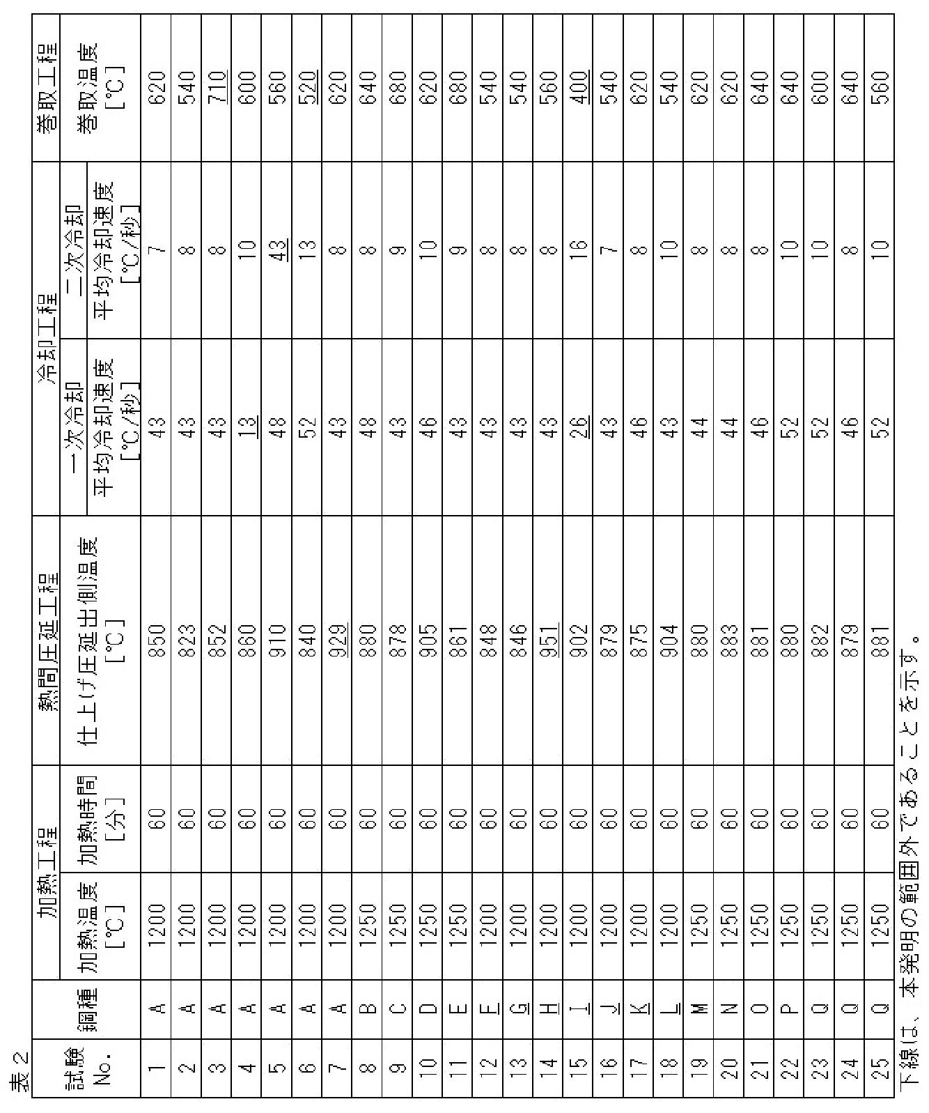
- a slab having the chemical composition shown in Table 1 was manufactured by the continuous casting method. Then, a hot-rolled steel sheet having a plate thickness of 3 mm was produced from these slabs by heating, hot rolling, cooling and winding conditions shown in Table 2. Secondary cooling in the cooling step was performed immediately after the completion of primary cooling. The rest other than the components shown in Table 1 are Fe and impurities. Further, the chemical composition of the sample collected from the manufactured hot rolled steel sheet was the same as the chemical composition of the slab shown in Table 1. In addition, in the hot-rolled steel sheets of all the examples, the ratio of the amount of solid solution C was 10% or less.
- JIS No. 5 tensile test pieces were taken from a direction perpendicular to the rolling direction, and subjected to a tensile test in accordance with JIS Z2241 (2011) to determine tensile strength (TS) and total elongation. (El) was measured.
- TS tensile strength
- El total elongation.
- a hole expansion test was conducted in accordance with JIS Z2256 (2010), and the hole expansion rate ( ⁇ ) was measured.
- the punching property is as follows: punching a hole having a diameter of 10 mm with a punching clearance of 12.5%, visually observing the end surface properties, and observing cracks having a size of 0.5 mm or more on the end surface, the evaluation is "not good".
- Comparative Example 3 since the winding temperature was higher than 700° C., the average lamella spacing of pearlite was coarsened to more than 0.20 ⁇ m. Therefore, TS 980 MPa or higher and ⁇ 45% or higher could not be achieved.
- Comparative Example 4 since the average cooling rate of the primary cooling in the cooling step was less than 40 ° C./sec, a large amount of proeutectoid ferrite was generated, and the pearlite fraction was less than 90%. Therefore, ⁇ of 45% or more could not be achieved.
- Comparative Example 5 since the average cooling rate of the secondary cooling was high, the pseudo pearlite was increased and the pearlite fraction was less than 90%. Therefore, ⁇ of 45% or more could not be achieved.
- Comparative Example 17 since the C content was high, the pro-eutectoid cementite was mixed in the balance structure, and the pearlite fraction was less than 90%. Therefore, El of 13% or more and ⁇ of 45% or more could not be achieved. In Comparative Example 18, ⁇ 45% or more could not be achieved because the Mn content was high.
Landscapes
- Chemical & Material Sciences (AREA)
- Engineering & Computer Science (AREA)
- Mechanical Engineering (AREA)
- Materials Engineering (AREA)
- Metallurgy (AREA)
- Organic Chemistry (AREA)
- Physics & Mathematics (AREA)
- Thermal Sciences (AREA)
- Crystallography & Structural Chemistry (AREA)
- Heat Treatment Of Sheet Steel (AREA)
- Heat Treatment Of Steel (AREA)
Abstract
Description
(1)化学組成が、質量%で、
C:0.50~1.00%、
Si:0.01~0.50%、
Mn:0.50~2.00%、
P:0.100%以下、
S:0.0100%以下、
Al:0.100%以下、
N:0.0100%以下、
Cr:0.50~2.00%、
Cu:0~1.00%、
Ni:0~1.00%、
Mo:0~0.50%、
Nb:0~0.10%、
V:0~1.00%、
Ti:0~1.00%、
B:0~0.0100%、
Ca:0~0.0050%、
REM:0~0.0050%、ならびに
残部:Feおよび不純物であり、
金属組織が、面積率で、
パーライト:90~100%、
疑似パーライト:0~10%、および
初析フェライト:0~1%であり、
前記パーライトの平均ラメラ間隔が0.20μm以下であり、
前記パーライトの平均パーライトブロック径が20.0μm以下であることを特徴とする、熱間圧延鋼板。
(2)前記化学組成が、質量%で、
Cu:0.01~1.00%、
Ni:0.01~1.00%、および
Mo:0.01~0.50%
Nb:0.01~0.10%、
V:0.01~1.00%、および
Ti:0.01~1.00%
の1種または2種以上を含むことを特徴とする、上記(1)に記載の熱間圧延鋼板。
(3)前記化学組成が、質量%で、B:0.0005~0.0100%を含むことを特徴とする、上記(1)または(2)に記載の熱間圧延鋼板。
(4)前記化学組成が、質量%で、
Ca:0.0005~0.0050%、および
REM:0.0005~0.0050%
の1種または2種を含むことを特徴とする、上記(1)~(3)のいずれか1項に記載の熱間圧延鋼板。
(5)980MPa以上の引張強度を有することを特徴とする、上記(1)~(4)のいずれか1項に記載の熱間圧延鋼板。
(6)上記(1)~(4)のいずれか1項に記載の化学組成を有するスラブを1100℃以上に加熱する工程、
加熱されたスラブを仕上げ圧延することを含む熱間圧延工程であって、前記仕上げ圧延の出側温度が820~920℃である熱間圧延工程、
得られた鋼板をAe1点まで40~80℃/秒の平均冷却速度で一次冷却し、次いでAe1点から巻取温度まで20℃/秒未満の平均冷却速度で二次冷却する工程、並びに
前記鋼板を540~700℃の巻取温度で巻き取る工程
を含むことを特徴とする、熱間圧延鋼板の製造方法。
本発明の実施形態に係る熱間圧延鋼板は、化学組成が、質量%で、
C:0.50~1.00%、
Si:0.01~0.50%、
Mn:0.50~2.00%、
P:0.100%以下、
S:0.0100%以下、
Al:0.100%以下、
N:0.0100%以下、
Cr:0.50~2.00%、
Cu:0~1.00%、
Ni:0~1.00%、
Mo:0~0.50%、
Nb:0~0.10%、
V:0~1.00%、
Ti:0~1.00%、
B:0~0.0100%、
Ca:0~0.0050%、
REM:0~0.0050%、ならびに
残部:Feおよび不純物であり、
金属組織が、面積率で、
パーライト:90~100%、
疑似パーライト:0~10%、および
初析フェライト:0~1%であり、
前記パーライトの平均ラメラ間隔が0.20μm以下であり、
前記パーライトの平均パーライトブロック径が20.0μm以下であることを特徴としている。
Cは、熱間圧延鋼板の強度確保のために必須の元素である。このような効果を十分に得るために、C含有量は0.50%以上とする。C含有量は0.53%以上、0.55%以上、0.60%以上または0.65%以上であってもよい。一方、Cを過度に含有すると、セメンタイトが析出し、十分なパーライト分率が得られない場合があるかまたは延性や溶接性が低下する場合がある。このため、C含有量は1.00%以下とする。C含有量は0.95%以下、0.90%以下、0.85%以下、0.80%以下または0.75%以下であってもよい。また、本発明の実施形態に係る熱間圧延鋼板では、鋼中の全C量(C含有量)に対する固溶C量(C含有量からセメンタイトとして析出するC量を差し引いた量)の割合は一般的に50%未満である。より具体的には、冷間圧延において高い圧下率で強加工を行った場合には、固溶C量が増加することがあるものの、このような冷間圧延を行わない本発明の実施形態に係る熱間圧延鋼板では、固溶C量の割合は一般的に50%よりもかなり低く、例えば30%以下、20%以下または10%以下である。
Siは、鋼の脱酸のために用いられる元素である。しかし、Si含有量が過剰であると化成処理性が低下するとともに、鋼板のミクロ組織にオーステナイトが残留することによって鋼板の打抜き性が悪化する。そのため、Si含有量は0.01~0.50%とする。Si含有量は0.05%以上、0.10%以上もしくは0.15%以上であってもよく、および/または0.45%以下、0.40%以下もしくは0.30%以下であってもよい。
Mnは、鋼の相変態を遅らせ、冷却途中で相変態が生じるのを防ぐために有効な元素である。しかし、Mn含有量が過剰になるとミクロ偏析またはマクロ偏析が起こりやすくなり、穴広げ性を劣化させる。そのため、Mn含有量は0.50~2.00%とする。Mn含有量は0.60%以上、0.70%以上もしくは0.90%以上であってもよく、および/または1.90%以下、1.70%以下、1.50%以下もしくは1.30%以下であってもよい。
P含有量は低いほど好ましく、過剰であると、成形性や溶接性に悪影響を及ぼすとともに、疲労特性も低下させるため、0.100%以下とする。好ましくは0.050%以下、より好ましくは0.040%以下または0.030%以下である。P含有量は0%であってもよいが、過剰な低減はコスト上昇を招くため、好ましくは0.0001%以上とする。
Sは、MnSを形成して破壊の起点として作用し、鋼板の穴広げ性を著しく低下させる。そのため、S含有量は0.0100%以下とする。S含有量は0.0090%以下であるのが好ましく、0.0060%以下または0.0010%以下であるのがより好ましい。S含有量は0%であってもよいが、過剰な低減はコスト上昇を招くため、好ましくは0.0001%以上とする。
Alは、鋼の脱酸のために用いられる元素である。しかし、Al含有量が過剰であると介在物が増加し、鋼板の加工性を劣化させる。そのため、Al含有量は0.100%以下とする。Al含有量は0%であってもよいが、0.005%以上または0.010%以上であるのが好ましい。一方、Al含有量は0.080%以下、0.050%以下または0.040%以下であってもよい。
Nは、鋼中のAlと結びついてAlNを形成し、ピン止め効果によりパーライトブロック径の大径化を阻害する。しかし、N含有量が過剰になるとその効果は飽和し、むしろ靱性低下を引き起こす。そのため、N含有量は0.0100%以下とする。N含有量は0.0090%以下、0.0080%以下または0.0050%以下であるのが好ましい。このような観点からはN含有量の下限を設ける必要はなく0%であってもよいが、N含有量を0.0010%未満に低減するには製鋼コストが嵩む。そのため、N含有量は0.0010%以上であることが好ましい。
Crは、パーライトのラメラ間隔を微細化させる効果を持ち、これによって鋼板の強度を担保することができる。このような効果を十分に得るために、Cr含有量の下限を0.50%、好ましくは0.60%とする。一方、Crを過剰に添加することにより疑似パーライトやベイナイトといった組織が出現しやすくなり、パーライト分率90%以上とすることが困難となる。そのため、Cr含有量の上限を2.00%、1.50%、1.25%好ましくは1.15%とする。
Cuは鋼に固溶して靱性を損なわずに強度を高めることができる元素である。Cu含有量は0%であってもよいが、上記効果を得るため、必要に応じて含有してもよい。しかし、その含有量が過剰であると析出物の増加により熱間での加工の際、表面に微小な割れを発生させることがある。したがって、Cu含有量は1.00%以下または0.60%以下であるのが好ましく、0.40%以下または0.25%以下がより好ましい。上記効果を十分に得るためには、Cu含有量は0.01%以上であるのが好ましく、0.05%以上であるのがより好ましい。
Niは鋼に固溶して靱性を損なわずに強度を高めることができる元素である。Ni含有量は0%であってもよいが、上記効果を得るため、必要に応じて含有させてもよい。しかし、Niは高価な元素であり、過剰添加はコストの上昇を招く。したがって、Ni含有量は1.00%以下または0.80%以下であるのが好ましく、0.60%以下または0.30%以下がより好ましい。上記効果を十分に得るためには、Ni含有量は0.10%以上であるのが好ましく、0.20%以上であるのがより好ましい。
Moは鋼の強度を高める元素である。Mo含有量は0%であってもよいが、上記効果を得るため、必要に応じて含有させてもよい。しかし、その含有量が過剰であると、強度増加に伴う靱性の低下が顕著となる。したがって、Moの含有量は0.50%以下または0.40%以下であるのが好ましく、0.20%以下または0.10%以下がより好ましい。上記効果を十分に得るためには、Mo含有量は0.01%以上であるのが好ましく、0.05%以上であることがより好ましい。
[V:0~1.00%]
[Ti:0~1.00%]
Nb、VおよびTiは、炭化物析出により鋼板強度の向上に寄与するため、必要に応じてこれらから選択される1種を単独で、または2種以上を複合して含有してもよい。しかしながら、いずれの元素も過剰に含有すると、多量の炭化物が生成し、鋼板の靱性を低下させる。そのため、Nb含有量は0.10%以下または0.08%以下が好ましく、0.05%以下がより好ましく、V含有量は1.00%以下または0.80%以下が好ましく、0.50%以下または0.20%以下がより好ましく、Ti含有量は1.00%以下または0.50%以下とすることが好ましく、0.20%以下または0.04%以下がより好ましい。一方、Nb、VおよびTi含有量の下限値は、いずれの元素も0.01%または0.03%であってよい。
Bは、粒界に偏析し、粒界強度を赤める効果を有するため、必要に応じて含有してもよい。しかし、その含有量が過剰であると、効果が飽和して原料コストが嵩む。そのため、B含有量は0.0100%以下とする。B含有量は0.0080%以下、0.0060%以下または0.0020%以下であるのが好ましい。上記効果を十分に得るためには、B含有量は0.0005%以上であるのが好ましく、0.0010%以上であるのがより好ましい。
Caは、破壊の起点となり加工性を劣化させる原因となる非金属介在物の形態を制御し、加工性を向上させる元素であるため、必要に応じて含有してもよい。しかし、その含有量が過剰であると効果が飽和して原料コストが嵩む。そのため、Ca含有量は0.0050%以下とする。Ca含有量は0.0040%以下または0.0030%以下であるのが好ましい。上記効果を十分に得るためには、Ca含有量は0.0005%以上であるのが好ましい。
REMは微量添加によって溶接部の靱性を向上させる元素である。REM含有量は0%であってもよいが、上記効果を得るため、必要に応じて含有させてもよい。しかし、過剰に添加すると逆に溶接性は悪化する。そのため、REM含有量は0.0050%以下または0.0040%以下であるのが好ましい。上記効果を十分に得るためには、REM含有量は0.0005%以上であるのが好ましく、0.0010%以上であるのがより好ましい。なお、REMはSc、Yおよびランタノイドの合計17元素の総称であり、REMの含有量は上記元素の合計量を意味する。
鋼板の金属組織をパーライトが主体の組織とすることによって、高い強度を保ちながらも延性および穴広げ性の優れた鋼板とすることが可能となる。パーライトが面積率で90%未満であると、延性が確保できないかおよび/または組織の不均一性のために穴広げ性を確保できない。そのため、本発明の実施形態に係る熱間圧延鋼板の金属組織中のパーライト含有量は、面積率で90%以上とし、好ましくは95%以上、96%以上、97%以上、98%以上または99%以上であり、100%であってもよい。
[初析フェライト:0~1%]
パーライト以外の残部組織は0%であってもよいが、残部組織が存在する場合には、それは疑似パーライトおよび初析フェライトのうち少なくとも1種からなる。残部組織を疑似パーライトおよび初析フェライトのうち少なくとも1種から構成すること、すなわち残部組織に残留オーステナイトを含めないことで良好な打抜き性を担保することが可能である。本発明において、「疑似パーライト」とは、フェライト相とセメンタイトが層状(ラメラ状)に分散するパーライトに対して、塊状に分散したセメンタイトを主体とする組織、より具体的にはこのような塊状のセメンタイトを当該組織中のセメンタイト全量に対して面積率で50%超含有する組織を言うものであり、一部にラメラ状のセメンタイトを含有していてもよい。また、本発明において、「初析フェライト」とは、熱間圧延後の冷却段階において初晶として析出した実質的にセメンタイトを含まない、すなわち結晶粒内のセメンタイトの分率が面積率で1%未満のフェライトを言うものである(例えば、図1(c)の参考図を参照)。なお、疑似パーライトは面積率で0~10%とし、例えば面積率で8%以下、6%以下、4%以下、3%以下、2%以下、または1%以下であってもよい。初析フェライトは面積率で0~1%とし、例えば面積率で0.8%以下または0.6%以下であってもよい。本発明の実施形態に係る熱間圧延鋼板においては、金属組織中に残留オーステナイト、初析セメンタイト、ベイナイトおよびマルテンサイトが存在しないかまたは実質的に存在しない。「実質的に存在しない」とは、これらの組織の面積率が合計でも0.5%未満であることを意味する。このような微小な組織の合計量を正確に測定することは困難であり、またその影響も無視できることから、これらの組織の合計量が0.5%未満となる場合には、存在しないものと判断することが可能である。
パーライト(ただし、前記の疑似パーライトを除く。)の平均ラメラ間隔は、鋼板の強度と強い相関を持ち、平均ラメラ間隔が小さいほど高い強度が得られる。さらに、同一成分であれば平均ラメラ間隔が小さいほど鋼板の穴広げ性が向上する。平均ラメラ間隔が0.20μm超では引張強度980MPa以上もの強度が得られないかおよび/または穴広げ性が低下するため、本発明の実施形態に係る熱間圧延鋼板における金属組織中のパーライトの平均ラメラ間隔は0.20μm以下、好ましくは0.15μm以下または0.10μm以下とする。なお、パーライトの平均ラメラ間隔の下限値は、特に限定されないが、例えば0.05μmまたは0.07μmであってもよい。
パーライトブロックとは、パーライト(ただし、前記の疑似パーライトを除く。)を構成するフェライトの結晶方位が揃った領域に相当するものである。ここで、パーライトの平均パーライトブロック径は、鋼板の局部延性および靱性と相関を持ち、平均パーライトブロック径が小さいほど穴広げ性が向上する。平均パーライトブロック径が20.0μm超では穴広げ性が劣化してしまうため、本発明の実施形態に係る熱間圧延鋼板の金属組織中の平均パーライトブロック径は20.0μm以下とし、好ましくは18.0μm以下であり、より好ましくは16.0μm以下である。なお、パーライトの平均パーライトブロック径の下限値は、特に限定されないが、例えば3.0μm、5.0μmまたは7.0μmであってもよい。
パーライトおよび残部組織の分率は以下のようにして求める。まず、鋼板の表面から板厚の1/4または3/4の位置から、鋼板の圧延方向および厚さ方向に平行な断面が観察面となるように試料を採取する。続いて、当該観察面を鏡面研磨し、ピクラール腐食液で腐食した後、走査電子顕微鏡(SEM)を用いて組織観察を行う。倍率は5000倍(測定領域:80μm×150μm)とし、得られた組織写真から点算法を用いてセメンタイトが層状となっている領域をパーライトと認定し(例えば、図1(a)の参考図を参照)、その分率を算出する。一方、フェライト相とセメンタイトが層状に分散するのではなく、塊状に分散したセメンタイトを主体とする組織の場合には、疑似パーライト(例えば、図1(b)の参考図を参照)と認定してその分率を算出する。また、ラス状の結晶粒の集合体であって、ラスの内部に長径20nm以上の鉄系炭化物を複数有し、さらにそれらの炭化物が単一のバリアント、すなわち同一の方向に伸長した鉄系炭化物群に属するものをベイナイトと認定する。また、塊状またはフィルム状の鉄系炭化物であって、円相当直径が300nm以上である領域を初析セメンタイトと認定する。図1(a)又は(b)のような組織である場合、観察される介在物は基本的にセメンタイトであり、エネルギー分散型X線分光器付き走査電子顕微鏡(SEM-EDS)などを用いて、個々の介在物をセメンタイト又は鉄系炭化物であることを同定する必要はない。セメンタイト又は鉄系炭化物であることに疑義が生じた場合のみ、必要に応じて、SEM観察とは別に、SEM-EDSなどを用いて介在物を分析することでよい。初析フェライトと残留オーステナイトは共に内部にセメンタイトの面積分率が1%未満であり、このような組織があればSEMによる組織観察の後、電子線後方散乱回折法(Electron Back Scatter Diffraction、EBSD)を用いて分析し、bcc構造の組織を初析フェライトと判定し、fcc構造の組織を残留オーステナイトと判定する。
平均ラメラ間隔は以下のようにして求める。まず、鋼板の表面から板厚の1/4または3/4の位置から、鋼板の圧延方向および厚さ方向に平行な断面が観察面となるように試料を採取する。続いて、当該観察面を鏡面研磨し、ピクラール腐食液で腐食した後、走査電子顕微鏡(SEM)を用いて組織観察を行う。倍率は5000倍(測定領域:80μm×150μm)とし、セメンタイト層が組織写真の紙面に対して垂直に横切っている箇所を10個以上選択する。ピクラール腐食液で腐食させて測定することにより、深さ方向の情報が得られるため、セメンタイト層を垂直に横切っている箇所がわかる。そのような箇所を10個以上選択して測定することにより、それぞれの箇所でラメラ間隔Sを求め、それらの平均をとることで平均ラメラ間隔とする。各箇所でのラメラ間隔の測定方法は以下のとおりとする。まず、セメンタイト層を10~30本横切るようにセメンタイト層に対して垂直に直線を引き、その直線の長さをLとする。またその直線が横切るセメンタイト層の数をNとする。このとき、当該箇所でのラメラ間隔Sは、S=L/Nによって求められる。
平均パーライトブロック径はEBSDを用いて測定する。まず、鋼板の表面から板厚の1/4または3/4の位置から、鋼板の圧延方向および厚さ方向に平行な断面が観察面となるように試料を採取する。続いて、観察面を鏡面研磨し、EBSDを用いて鉄の結晶方位を測定し、結晶粒界を求める。結晶粒界は結晶方位が15°変化する境界と定義する。測定領域は100μm×200μm、測定点間隔は0.2μmピッチとする。最後に、上記結晶粒界によって囲まれる領域の面積から円相当直径を求め、測定領域内におけるすべての結晶粒について算出された円相当直径のArea Fraction法による平均値を平均パーライトブロック径と定義する。
上記の化学組成および組織を有する熱間圧延鋼板によれば、高い引張強度、具体的には980MPa以上の引張強度を達成することができる。引張強度を980MPa以上とするのは、自動車における車体の軽量化の要求を満足させるためである。引張強度は、好ましくは1050MPa以上であり、より好ましくは1100MPa以上である。上限値については特に規定する必要はないが、例えば、引張強度は1500MPa以下、1400MPa以下または1300MPa以下であってよい。同様に、上記の化学組成および組織を有する熱間圧延鋼板によれば、高い延性を達成することができ、より具体的には13%以上、好ましくは15%以上、より好ましくは17%以上の全伸びを達成することができる。上限値については特に規定する必要はないが、例えば、全伸びは30%以下または25%以下であってよい。さらに、上記の化学組成および組織を有する熱間圧延鋼板によれば、優れた穴広げ性を達成することができ、より具体的には45%以上、好ましくは50%以上、より好ましくは55%以上の穴広げ率を達成することができる。上限値については特に規定する必要はないが、例えば、穴広げ率は80%以下または70%以下であってよい。引張強度および全伸びは、熱間圧延鋼板の圧延方向に直角な方向からJIS5号引張試験片を採取し、JIS Z2241(2011)に準拠して引張試験を行うことで測定される。一方、穴広げ率は、JIS Z2256(2010)に準拠して穴広げ試験を行うことで測定される。
本発明の実施形態に係る熱間熱延鋼板は、一般的に1.0~6.0mmの板厚を有する。特に限定されないが、板厚は1.2mm以上もしくは2.0mm以上であってもよく、および/または5.0mm以下もしくは4.0mm以下であってもよい。
本発明の実施形態に係る熱間圧延鋼板の製造方法は、上で説明した化学組成を有するスラブを1100℃以上に加熱する工程、
加熱されたスラブを仕上げ圧延することを含む熱間圧延工程であって、前記仕上げ圧延の出側温度が820~920℃である熱間圧延工程、
得られた鋼板をAe1点まで40~80℃/秒の平均冷却速度で一次冷却し、次いでAe1点から巻取温度まで20℃/秒未満の平均冷却速度で二次冷却する工程、並びに
前記鋼板を540~700℃の巻取温度で巻き取る工程
を含むことを特徴としている。以下、各工程について詳しく説明する。
まず、上で説明した化学組成を有するスラブが熱間圧延前に加熱される。スラブの加熱温度は、Ti炭窒化物等を十分に再固溶させるため、1100℃以上とする。上限値は特に規定しないが、例えば1250℃であってもよい。また、加熱時間は、特に限定されないが、例えば30分以上であってもよく、および/または120分以下であってもよい。なお、使用するスラブは、生産性の観点から連続鋳造法において鋳造することが好ましいが、造塊法または薄スラブ鋳造法によって製造してもよい。
(粗圧延)
本方法では、例えば、加熱されたスラブに対し、板厚調整等のために、仕上げ圧延の前に粗圧延を施してもよい。粗圧延は、所望のシートバー寸法が確保できればよく、その条件は特に限定されない。
加熱されたスラブまたはそれに加えて必要に応じて粗圧延されたスラブは、次に仕上げ圧延を施され、当該仕上げ圧延における出側温度は820~920℃に制御される。仕上げ圧延の出側温度が920℃超であると、オーステナイトが粗大化して最終製品の前記平均パーライトブロック径の条件(すなわち20.0μm以下)を満たさなくなる。そのため、仕上げ温度の出側温度の上限は920℃、好ましくは900℃、さらに好ましくは880℃とする。このような観点からはAr3点以上であれば特に仕上げ圧延の出側温度に下限を設ける必要はないが、低温になるほど鋼板の変形抵抗が増大し、圧延機に多大なる負担をかけ、設備トラブルの原因となりうる。そのため、仕上げ圧延の出側温度の下限を820℃とする。
仕上げ圧延終了後、鋼板の冷却を行う。冷却工程は、さらに、一次冷却および二次冷却に細分化される。
一次冷却においては、上記の仕上げ圧延の出側温度から、40~80℃/秒の平均冷却速度でAe1点まで冷却する。上記温度までの平均冷却速度が40℃/秒未満であると、初析フェライトおよび/または初析セメンタイトが析出し、上記パーライト分率の目標値(90%以上)が達成できなくなるおそれがある。一次冷却の平均冷却速度は43℃/秒以上または45℃/秒以上であってもよい。一方、平均冷却速度が高くなりすぎると、鋼板を均一に冷却することができなくなり、材質のばらつきが生じる虞がある。したがって、一次冷却の平均冷却速度は80℃/秒以下とし、例えば70℃/秒以下であってもよい。なお、Ae1(℃)は、下記の式を用いて求めることができる。
Ae1(℃)=723-10.7×[Mn]+29.1×[Si]
但し、式中の[元素記号]は、それぞれ、質量%での各元素の含有量を示す。
続いて、二次冷却では、Ae1点から巻取温度(すなわち540~700℃の温度域)まで20℃/秒未満の平均冷却速度で冷却する。このように冷却速度を一次冷却と比べて遅くすることにより、ラメラの方向がよりランダムなパーライト組織を生成することができるとともに、ラメラ間隔を細かくして穴広げ性を向上させることができる。一方、上記温度域までの平均冷却速度が高いと、ラメラ間隔が鋼板内で不均一となってしまい、穴広げ性が劣化するおそれがあるか、または疑似パーライトが多く生成してパーライト分率の目標値(90%以上)が達成できなくなるおそれがある。したがって、上記二次冷却の平均冷却速度は20℃/秒未満とし、好ましくは15℃/秒以下、より好ましくは10℃/秒以下、最も好ましくは10℃/秒以下である。二次冷却は、フェライトの生成を確実に抑制するために、一次冷却終了後直ちに行うことが好ましい。
冷却工程の後、鋼板を巻き取る。巻取時の鋼板の温度は540~700℃とする。巻取温度を540~700℃に制御することで、巻き取りの中で組織を適切に変態させてパーライトの平均ラメラ間隔を微細化することにより、延性および穴広げ性を損なわずに熱間圧延鋼板を高強度化することが可能となる。一方で、巻取温度が540℃未満の場合、疑似パーライトやベイナイト等の他の組織が出現し、上記パーライト分率90%以上を達成することが困難となる。したがって、巻取温度は540℃以上とし、550℃以上または600℃以上であってもよい。また、巻取温度が700℃超の場合、パーライトの平均ラメラ間隔が大きくなり、十分な強度および/または穴広げ性を担保することができなくなる。このため、巻取温度は700℃以下とし、680℃以下または650℃以下であってもよい。巻取工程後の条件は、特に限定されない。


Claims (6)
- 化学組成が、質量%で、
C:0.50~1.00%、
Si:0.01~0.50%、
Mn:0.50~2.00%、
P:0.100%以下、
S:0.0100%以下、
Al:0.100%以下、
N:0.0100%以下、
Cr:0.50~2.00%、
Cu:0~1.00%、
Ni:0~1.00%、
Mo:0~0.50%、
Nb:0~0.10%、
V:0~1.00%、
Ti:0~1.00%、
B:0~0.0100%、
Ca:0~0.0050%、
REM:0~0.0050%、ならびに
残部:Feおよび不純物であり、
金属組織が、面積率で、
パーライト:90~100%、
疑似パーライト:0~10%、および
初析フェライト:0~1%であり、
前記パーライトの平均ラメラ間隔が0.20μm以下であり、
前記パーライトの平均パーライトブロック径が20.0μm以下であることを特徴とする、熱間圧延鋼板。 - 前記化学組成が、質量%で、
Cu:0.01~1.00%、
Ni:0.01~1.00%、および
Mo:0.01~0.50%
Nb:0.01~0.10%、
V:0.01~1.00%、および
Ti:0.01~1.00%
の1種または2種以上を含むことを特徴とする、請求項1に記載の熱間圧延鋼板。 - 前記化学組成が、質量%で、B:0.0005~0.0100%を含むことを特徴とする、請求項1または2に記載の熱間圧延鋼板。
- 前記化学組成が、質量%で、
Ca:0.0005~0.0050%、および
REM:0.0005~0.0050%
の1種または2種を含むことを特徴とする、請求項1~3のいずれか1項に記載の熱間圧延鋼板。 - 980MPa以上の引張強度を有することを特徴とする、請求項1~4のいずれか1項に記載の熱間圧延鋼板。
- 請求項1~4のいずれか1項に記載の化学組成を有するスラブを1100℃以上に加熱する工程、
加熱されたスラブを仕上げ圧延することを含む熱間圧延工程であって、前記仕上げ圧延の出側温度が820~920℃である熱間圧延工程、
得られた鋼板をAe1点まで40~80℃/秒の平均冷却速度で一次冷却し、次いでAe1点から巻取温度まで20℃/秒未満の平均冷却速度で二次冷却する工程、並びに
前記鋼板を540~700℃の巻取温度で巻き取る工程
を含むことを特徴とする、熱間圧延鋼板の製造方法。
Priority Applications (6)
| Application Number | Priority Date | Filing Date | Title |
|---|---|---|---|
| JP2021504083A JP7131687B2 (ja) | 2019-03-06 | 2020-03-02 | 熱間圧延鋼板およびその製造方法 |
| MX2021008043A MX2021008043A (es) | 2019-03-06 | 2020-03-02 | Lamina de acero laminada en caliente y metodo para producir la misma. |
| KR1020217027642A KR102649506B1 (ko) | 2019-03-06 | 2020-03-02 | 열간 압연 강판 및 그의 제조 방법 |
| CN202080011420.3A CN113396232B (zh) | 2019-03-06 | 2020-03-02 | 热轧钢板及其制造方法 |
| US17/296,496 US12534772B2 (en) | 2019-03-06 | 2020-03-02 | Hot rolled steel sheet and method for producing same |
| EP20767363.3A EP3936629A4 (en) | 2019-03-06 | 2020-03-02 | Hot-rolled steel sheet and production method therefor |
Applications Claiming Priority (2)
| Application Number | Priority Date | Filing Date | Title |
|---|---|---|---|
| JP2019040948 | 2019-03-06 | ||
| JP2019-040948 | 2019-03-06 |
Publications (1)
| Publication Number | Publication Date |
|---|---|
| WO2020179737A1 true WO2020179737A1 (ja) | 2020-09-10 |
Family
ID=72337796
Family Applications (1)
| Application Number | Title | Priority Date | Filing Date |
|---|---|---|---|
| PCT/JP2020/008710 Ceased WO2020179737A1 (ja) | 2019-03-06 | 2020-03-02 | 熱間圧延鋼板およびその製造方法 |
Country Status (7)
| Country | Link |
|---|---|
| US (1) | US12534772B2 (ja) |
| EP (1) | EP3936629A4 (ja) |
| JP (1) | JP7131687B2 (ja) |
| KR (1) | KR102649506B1 (ja) |
| CN (1) | CN113396232B (ja) |
| MX (1) | MX2021008043A (ja) |
| WO (1) | WO2020179737A1 (ja) |
Cited By (4)
| Publication number | Priority date | Publication date | Assignee | Title |
|---|---|---|---|---|
| WO2021176999A1 (ja) | 2020-03-02 | 2021-09-10 | 日本製鉄株式会社 | 熱間圧延鋼板 |
| JPWO2023026582A1 (ja) * | 2021-08-24 | 2023-03-02 | ||
| WO2026070267A1 (ja) * | 2024-09-27 | 2026-04-02 | Jfeスチール株式会社 | 熱延鋼板およびその製造方法 |
| WO2026070266A1 (ja) * | 2024-09-27 | 2026-04-02 | Jfeスチール株式会社 | 熱延鋼板およびその製造方法 |
Families Citing this family (2)
| Publication number | Priority date | Publication date | Assignee | Title |
|---|---|---|---|---|
| CN115404403B (zh) * | 2022-08-25 | 2023-07-18 | 北京首钢股份有限公司 | 一种压缩机阀片用热轧带钢及其制备方法、压缩机阀片 |
| KR20250090683A (ko) * | 2023-12-13 | 2025-06-20 | 주식회사 포스코 | 고탄소 열연강판, 이를 이용한 고탄소강 제품 및 이들의 제조 방법 |
Citations (7)
| Publication number | Priority date | Publication date | Assignee | Title |
|---|---|---|---|---|
| JPH08302428A (ja) * | 1995-05-10 | 1996-11-19 | Nisshin Steel Co Ltd | ばね用高強度鋼帯の製造方法 |
| JP2001164322A (ja) | 1999-09-29 | 2001-06-19 | Nkk Corp | 薄鋼板および薄鋼板の製造方法 |
| JP2011012316A (ja) | 2009-07-02 | 2011-01-20 | Nippon Steel Corp | 打抜き性に優れた軟質高炭素鋼板及びその製造方法 |
| JP2011099132A (ja) | 2009-11-04 | 2011-05-19 | Jfe Steel Corp | 引張強さが1500MPa以上の高強度鋼板およびその製造方法ならびに冷間圧延用素材 |
| JP2011530659A (ja) | 2008-08-14 | 2011-12-22 | ポスコ | 高炭素熱延鋼板およびその製造方法 |
| WO2014196586A1 (ja) * | 2013-06-05 | 2014-12-11 | 日新製鋼株式会社 | スチールベルト用鋼板およびその製造法並びにスチールベルト |
| JP2016098414A (ja) | 2014-11-21 | 2016-05-30 | 株式会社神戸製鋼所 | 高強度高延性鋼板 |
Family Cites Families (19)
| Publication number | Priority date | Publication date | Assignee | Title |
|---|---|---|---|---|
| JPH09324212A (ja) * | 1996-06-07 | 1997-12-16 | Kawasaki Steel Corp | 焼入性と冷間加工性に優れた高炭素熱延鋼帯の製造方法 |
| EP1191115A4 (en) | 2000-01-27 | 2005-04-06 | Jfe Steel Corp | HIGH CARBON STEEL PLATE AND METHOD FOR THE PRODUCTION THEREOF |
| KR100742871B1 (ko) | 2001-08-16 | 2007-07-26 | 주식회사 포스코 | 가공 절단면이 미려한 고탄소강대의 제조방법 |
| CN1304618C (zh) * | 2002-04-05 | 2007-03-14 | 新日本制铁株式会社 | 耐磨性和延性优良的珠光体系钢轨及其制造方法 |
| US20050199322A1 (en) | 2004-03-10 | 2005-09-15 | Jfe Steel Corporation | High carbon hot-rolled steel sheet and method for manufacturing the same |
| JP5050386B2 (ja) * | 2006-03-31 | 2012-10-17 | Jfeスチール株式会社 | ファインブランキング加工性に優れた鋼板およびその製造方法 |
| JP5630004B2 (ja) | 2009-11-04 | 2014-11-26 | Jfeスチール株式会社 | 引張強さが1500MPa以上の高強度鋼板およびその製造方法 |
| JP5440203B2 (ja) | 2010-01-22 | 2014-03-12 | Jfeスチール株式会社 | 高炭素熱延鋼板の製造方法 |
| JP6104163B2 (ja) | 2010-09-16 | 2017-03-29 | ポスコPosco | 高炭素熱延鋼板、冷延鋼板およびその製造方法 |
| JP5224009B2 (ja) * | 2011-03-14 | 2013-07-03 | 新日鐵住金株式会社 | 鋼線材及びその製造方法 |
| KR101384798B1 (ko) | 2011-12-15 | 2014-04-15 | 주식회사 포스코 | 고탄소 열연강판, 냉연강판 및 그 제조방법 |
| KR101417260B1 (ko) | 2012-04-10 | 2014-07-08 | 주식회사 포스코 | 재질 균일성이 우수한 고탄소 열연강판 및 이의 제조방법 |
| EP2952601B1 (en) * | 2013-01-31 | 2017-09-27 | JFE Steel Corporation | Electric-resistance-welded steel pipe |
| CA2907609C (en) | 2013-03-27 | 2017-12-19 | Jfe Steel Corporation | Pearlitic rail and method for manufacturing pearlitic rail |
| CN106460117A (zh) | 2014-06-11 | 2017-02-22 | 杰富意钢铁株式会社 | 铁路车辆用车轮及铁路车辆用车轮的制造方法 |
| US10487379B2 (en) * | 2014-08-08 | 2019-11-26 | Nippon Steel Corporation | High-carbon steel wire rod with excellent wire drawability |
| EP3228721A4 (en) * | 2014-12-05 | 2018-07-11 | Nippon Steel & Sumitomo Metal Corporation | High-carbon-steel wire rod having excellent wire drawing properties |
| WO2016174500A1 (fr) * | 2015-04-30 | 2016-11-03 | Aperam | Acier inoxydable martensitique, procédé de fabrication d'un demi-produit en cet acier et outil de coupe réalisé à partir de ce demi-produit |
| KR101917447B1 (ko) | 2016-12-20 | 2018-11-09 | 주식회사 포스코 | 고온연신 특성이 우수한 고강도 강판, 온간프레스 성형부재 및 이들의 제조방법 |
-
2020
- 2020-03-02 US US17/296,496 patent/US12534772B2/en active Active
- 2020-03-02 WO PCT/JP2020/008710 patent/WO2020179737A1/ja not_active Ceased
- 2020-03-02 EP EP20767363.3A patent/EP3936629A4/en active Pending
- 2020-03-02 KR KR1020217027642A patent/KR102649506B1/ko active Active
- 2020-03-02 MX MX2021008043A patent/MX2021008043A/es unknown
- 2020-03-02 JP JP2021504083A patent/JP7131687B2/ja active Active
- 2020-03-02 CN CN202080011420.3A patent/CN113396232B/zh active Active
Patent Citations (7)
| Publication number | Priority date | Publication date | Assignee | Title |
|---|---|---|---|---|
| JPH08302428A (ja) * | 1995-05-10 | 1996-11-19 | Nisshin Steel Co Ltd | ばね用高強度鋼帯の製造方法 |
| JP2001164322A (ja) | 1999-09-29 | 2001-06-19 | Nkk Corp | 薄鋼板および薄鋼板の製造方法 |
| JP2011530659A (ja) | 2008-08-14 | 2011-12-22 | ポスコ | 高炭素熱延鋼板およびその製造方法 |
| JP2011012316A (ja) | 2009-07-02 | 2011-01-20 | Nippon Steel Corp | 打抜き性に優れた軟質高炭素鋼板及びその製造方法 |
| JP2011099132A (ja) | 2009-11-04 | 2011-05-19 | Jfe Steel Corp | 引張強さが1500MPa以上の高強度鋼板およびその製造方法ならびに冷間圧延用素材 |
| WO2014196586A1 (ja) * | 2013-06-05 | 2014-12-11 | 日新製鋼株式会社 | スチールベルト用鋼板およびその製造法並びにスチールベルト |
| JP2016098414A (ja) | 2014-11-21 | 2016-05-30 | 株式会社神戸製鋼所 | 高強度高延性鋼板 |
Non-Patent Citations (1)
| Title |
|---|
| See also references of EP3936629A4 |
Cited By (8)
| Publication number | Priority date | Publication date | Assignee | Title |
|---|---|---|---|---|
| WO2021176999A1 (ja) | 2020-03-02 | 2021-09-10 | 日本製鉄株式会社 | 熱間圧延鋼板 |
| KR20220146419A (ko) | 2020-03-02 | 2022-11-01 | 닛폰세이테츠 가부시키가이샤 | 열간 압연 강판 |
| US12534787B2 (en) | 2020-03-02 | 2026-01-27 | Nippon Steel Corporation | Hot rolled steel sheet |
| JPWO2023026582A1 (ja) * | 2021-08-24 | 2023-03-02 | ||
| WO2023026582A1 (ja) * | 2021-08-24 | 2023-03-02 | 日本製鉄株式会社 | 熱間圧延鋼板 |
| JP7633565B2 (ja) | 2021-08-24 | 2025-02-20 | 日本製鉄株式会社 | 熱間圧延鋼板 |
| WO2026070267A1 (ja) * | 2024-09-27 | 2026-04-02 | Jfeスチール株式会社 | 熱延鋼板およびその製造方法 |
| WO2026070266A1 (ja) * | 2024-09-27 | 2026-04-02 | Jfeスチール株式会社 | 熱延鋼板およびその製造方法 |
Also Published As
| Publication number | Publication date |
|---|---|
| EP3936629A4 (en) | 2024-04-24 |
| JP7131687B2 (ja) | 2022-09-06 |
| JPWO2020179737A1 (ja) | 2021-10-21 |
| CN113396232B (zh) | 2023-02-21 |
| KR20210120087A (ko) | 2021-10-06 |
| MX2021008043A (es) | 2021-08-05 |
| US12534772B2 (en) | 2026-01-27 |
| EP3936629A1 (en) | 2022-01-12 |
| US20220033927A1 (en) | 2022-02-03 |
| KR102649506B1 (ko) | 2024-03-22 |
| CN113396232A (zh) | 2021-09-14 |
Similar Documents
| Publication | Publication Date | Title |
|---|---|---|
| JP5408387B2 (ja) | 局部変形能に優れた高強度熱延鋼板とその製造方法 | |
| US10435762B2 (en) | High-yield-ratio high-strength cold-rolled steel sheet and method of producing the same | |
| CN103403208B (zh) | 热轧钢板及其制造方法 | |
| JP5858174B2 (ja) | 低降伏比高強度冷延鋼板およびその製造方法 | |
| JP5370016B2 (ja) | 穴広げ性に優れた高強度熱延鋼板及びその製造方法 | |
| JP7131687B2 (ja) | 熱間圧延鋼板およびその製造方法 | |
| JP6597938B1 (ja) | 高強度冷延鋼板、高強度めっき鋼板及びそれらの製造方法 | |
| JP7498407B2 (ja) | 鋼板及び鋼板の製造方法 | |
| JP6866933B2 (ja) | 熱延鋼板及びその製造方法 | |
| KR20130121940A (ko) | 가공성이 우수한 고항복비를 갖는 고강도 냉연 강판 및 그 제조 방법 | |
| WO2019103120A1 (ja) | 熱延鋼板及びその製造方法 | |
| JP7356066B2 (ja) | 熱間圧延鋼板 | |
| KR20240154605A (ko) | 고강도 강판 및 그의 제조 방법 | |
| CN114599813B (zh) | 热轧钢板 | |
| JP7633565B2 (ja) | 熱間圧延鋼板 | |
| JP7201136B1 (ja) | 鋼矢板及びその製造方法 | |
| WO2024096073A1 (ja) | 熱延コイル |
Legal Events
| Date | Code | Title | Description |
|---|---|---|---|
| 121 | Ep: the epo has been informed by wipo that ep was designated in this application |
Ref document number: 20767363 Country of ref document: EP Kind code of ref document: A1 |
|
| ENP | Entry into the national phase |
Ref document number: 2021504083 Country of ref document: JP Kind code of ref document: A |
|
| ENP | Entry into the national phase |
Ref document number: 20217027642 Country of ref document: KR Kind code of ref document: A |
|
| NENP | Non-entry into the national phase |
Ref country code: DE |
|
| ENP | Entry into the national phase |
Ref document number: 2020767363 Country of ref document: EP Effective date: 20211006 |
|
| WWG | Wipo information: grant in national office |
Ref document number: 17296496 Country of ref document: US |