WO2020179688A1 - 室内空気処理装置及びその作動方法 - Google Patents
室内空気処理装置及びその作動方法 Download PDFInfo
- Publication number
- WO2020179688A1 WO2020179688A1 PCT/JP2020/008393 JP2020008393W WO2020179688A1 WO 2020179688 A1 WO2020179688 A1 WO 2020179688A1 JP 2020008393 W JP2020008393 W JP 2020008393W WO 2020179688 A1 WO2020179688 A1 WO 2020179688A1
- Authority
- WO
- WIPO (PCT)
- Prior art keywords
- air
- chamber
- indoor
- new
- operation pattern
- Prior art date
- Legal status (The legal status is an assumption and is not a legal conclusion. Google has not performed a legal analysis and makes no representation as to the accuracy of the status listed.)
- Ceased
Links
Images









Classifications
-
- F—MECHANICAL ENGINEERING; LIGHTING; HEATING; WEAPONS; BLASTING
- F24—HEATING; RANGES; VENTILATING
- F24F—AIR-CONDITIONING; AIR-HUMIDIFICATION; VENTILATION; USE OF AIR CURRENTS FOR SCREENING
- F24F7/00—Ventilation
- F24F7/003—Ventilation in combination with air cleaning
Definitions
- an object of the present invention to provide an indoor air treatment device which can improve the quality of indoor air and is easy to use and an operation method thereof.
- the indoor air treatment device includes an intake chamber, an air purification chamber, an air flow distribution chamber and an exhaust chamber.
- An intake fan is provided in the intake chamber.
- the air purification chamber is provided with an air purification assembly.
- An exhaust fan is provided in the exhaust chamber. Both the intake chamber and the airflow distribution chamber communicate with the air purification chamber.
- the intake chamber has an air outlet for communicating with the indoor space.
- the exhaust chamber has a return air port for communicating with the indoor space and an exhaust port for communicating with the outdoor space.
- the airflow distribution chamber includes a new wind partition chamber and a suction partition chamber.
- the new wind partition chamber communicates with the air purification chamber.
- the fresh air partition chamber and the suction partition chamber are connected by a communication port.
- the new wind partition chamber has a first new air outlet and a second new air outlet for communicating with the outdoor space.
- the suction partition chamber has a suction port for communicating with the indoor space.
- the first new air vent is provided with a first valve plate driven by the first drive mechanism.
- the second fresh air outlet is provided with a second valve plate driven by the second drive mechanism.
- the first valve plate is located in a state where the first new air outlet is closed, a state where the communication port is closed, and between the first new air port and the communication port. Driven by the first drive mechanism so that each of the states can be moved.
- the second valve plate is driven by the second drive mechanism so as to close or open the second fresh air outlet.
- the exhaust chamber does not communicate with the airflow distribution chamber, the air purification chamber, or the intake chamber.
- the intake chamber, the air purification chamber, the air flow distribution chamber, and the exhaust chamber are all provided in the case.
- the outer surface of the case includes a first mounting surface and a second mounting surface extending along the longitudinal direction of the case.
- the first fresh air outlet is exposed from the first mounting surface.
- the second fresh air outlet is exposed from the second mounting surface.
- One exhaust port is exposed on each of the first mounting surface and the second mounting surface.
- a first mounting interface and a second mounting interface are further provided on each of the first mounting surface and the second mounting surface.
- the indoor air treatment device can be mounted by the first mounting interface or the second mounting interface.
- the first mounting surface and the second mounting surface can be attached to two walls at a wall angle, respectively. More preferably, the angle formed by the first mounting surface and the second mounting surface is a right angle.
- the suction partition chamber has two suction ports.
- the intake chamber has two air outlets.
- the outer surface of the case further includes a first connecting surface and a second connecting surface extending along the longitudinal direction of the case. One air outlet and one suction port are exposed on the first connecting surface. One air outlet and one suction port are also exposed on the second connecting surface.
- a partition wall is provided between the fresh air partition chamber and the suction partition chamber.
- the communication port includes a first communication port and a second communication port provided on the partition wall.
- the first valve plate moves to each of a state in which the first fresh air port is closed, a state in which the first communication port is closed, and a state which is located between the first fresh air port and the first communication port. It is driven by a first drive mechanism so that it can be.
- the second valve plate moves to a state in which the second new air outlet is closed, a state in which the second communication port is closed, and a state in which the second valve plate is located between the second new air port and the second communication port. Is driven by a second drive mechanism.
- the first new air outlet is in a state of being cut off from the outdoor space
- the operation method of the indoor air treatment device is as follows: new wind introduction operation pattern, internal circulation operation pattern, and new wind introduction. Includes an operating pattern in which internal circulation occurs simultaneously.
- the new wind introduction operation pattern is 1a) A step in which the first valve plate is driven by the first drive mechanism so as to move to a state in which the communication port is closed. 1b) a step in which the second valve plate is driven by the second drive mechanism so as to move to a state in which the second fresh air opening is opened, and the second fresh air opening becomes in communication with the outdoor space; 1c) By activating the rotation of the intake fan, the fresh air in the outdoor space enters the air purification chamber through the second new air outlet and the new air partition chamber in order, and after being purified by the air purification assembly, the intake chamber and the air blower. And sequentially into the interior space through the mouth.
- the internal circulation operation pattern is 2a) a step in which the first valve plate is driven by the first drive mechanism so as to move to a state in which the communication port is opened, and the communication port establishes communication between the fresh air partition chamber and the suction partition chamber; 2b) a step in which the second valve plate is driven by the second drive mechanism so as to move to a state in which the second fresh air outlet is closed, and the second fresh air outlet is shut off from the outdoor space; 2c) The rotation of the intake fan is started, and the air in the indoor space enters the air purification chamber through the suction port, the suction partition chamber, the communication port, and the fresh air partition chamber in order, and is purified by the air purification assembly, and then the intake chamber. , And then blowing the air into the indoor space through the air outlet in order.
- the operation pattern in which new wind is introduced and internal circulation is performed at the same time is 3a) a step in which the first valve plate is driven by the first drive mechanism so as to move to a state in which the communication opening is opened, and the communication opening allows the fresh air partition chamber and the suction partition chamber to communicate with each other; 3b) A step in which the second valve plate is driven by the second drive mechanism so as to move to a state in which the second new air outlet is opened so that the second new air outlet communicates with the outdoor space. 3c) The rotation of the intake fan is activated, and the fresh air in the outdoor space enters the air purification chamber through the second new air outlet and the new air partition chamber in this order, and is purified by the air purification assembly, and then the intake chamber and the air blower.
- the air is introduced into the indoor space through the mouth in order, and the air in the indoor space passes through the suction port, the suction partition chamber, the communication port, and the fresh air partition chamber in order to enter the air purification chamber, and after being purified by the air purification assembly, the intake chamber Includes an operating pattern in which new wind is introduced and internal circulation is performed at the same time, including the step of feeding into the chamber space through the air outlets in order.
- an exhaust operation pattern is further included.
- the exhaust operation pattern is 4a) A step in which the rotation of the exhaust fan is activated and the air in the indoor space is discharged to the outdoor space through the return air port, the exhaust chamber, and the exhaust port in this order. including.
- the exhaust operation patterns include a new wind introduction operation pattern, an internal circulation operation pattern, and an operation pattern in which new wind introduction and internal circulation are performed at the same time. It will be done at the same time as any one of them.
- Another method of operating the indoor air treatment device is to work using the above indoor air treatment device, the second new air outlet is in a state of being cut off from the outdoor space, and the new wind introduction operation pattern, the internal circulation operation pattern, and the new wind An operation pattern in which introduction and internal circulation are performed simultaneously is included.
- the new wind introduction operation pattern is Ia) A step in which the first valve plate is driven by the first drive mechanism so as to move to a state in which the communication port is closed, and the first new air port communicates with the outdoor space. 1b) The rotation of the intake fan is started, and the fresh air in the outdoor space enters the air purification chamber through the first fresh air inlet and the fresh air partition chamber in this order, and is purified by the air purification assembly, and then the intake chamber and the air blower. Steps to send into the indoor space through the mouth in order, including.
- the internal circulation operation pattern is IIa) a step in which the first valve plate is driven by the first drive mechanism so as to move to a state in which the first fresh air outlet is closed, and the first fresh air outlet is shut off from the outdoor space; IIb) By activating the rotation of the intake fan, the air in the indoor space enters the air purification chamber through the suction port, the suction partition chamber, the communication port, and the new wind partition chamber in this order, and after being purified by the air purification assembly, the intake chamber. , A step of blowing the air into the indoor space through the blower opening in order, including.
- the operation pattern in which new wind is introduced and internal circulation is performed at the same time is IIIa)
- the first valve plate is driven by the first drive mechanism so as to move to a state located between the first new air outlet and the communication port, and the first new air outlet communicates with the outdoor space.
- fresh air in the outdoor space enters the air purification chamber through the first new air outlet and the new air partition chamber in order, and after being purified by the air purification assembly, the intake chamber, the air blow The air is introduced into the indoor space through the mouth in order, and the air in the indoor space passes through the suction port, the suction partition chamber, the communication port, and the fresh air partition chamber in order to enter the air purification chamber, and after being purified by the air purification assembly, the intake chamber ,
- a step of blowing the air into the indoor space through the blower opening in order including.
- an exhaust operation pattern is further included.
- the exhaust operation pattern is IVa) A step in which the rotation of the exhaust fan is activated and the air in the indoor space is discharged to the outdoor space through the return air port, the exhaust chamber, and the exhaust port in this order. including.
- the exhaust operation pattern is one of a new wind introduction operation pattern, an internal circulation operation pattern, and an operation pattern in which new wind introduction and internal circulation are performed at the same time. Can be done at the same time.
- the indoor air treatment device and its operating method have the following beneficial effects.
- the first drive mechanism and the second drive mechanism can drive the movement by the first valve plate and the second valve plate.
- the first drive mechanism and the second drive mechanism By controlling the first drive mechanism and the second drive mechanism, it is possible to realize the switching control to the air flow path in the air flow distribution chamber by the first valve plate and the second valve plate.
- air enters the air flow distribution chamber from indoors or outdoors, enters the air purification chamber to be purified, and finally enters the indoor space via the intake chamber and the air outlet.
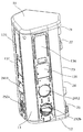
- the front view of an indoor air processing apparatus is shown.
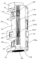
- the perspective view of an indoor air processing apparatus is shown.
- a schematic view of the surrounding airflow transmitted from the air purification/ventilation device to the indoor space is shown, and the white arrow in the figure shows the airflow.
- a perspective view of the indoor air treatment device as viewed from the left rear side is shown.
- the perspective view which looked at the indoor air treatment equipment from which the 1st end cap, the main exterior surface, and the 2nd connection surface was seen from the right front side is shown.
- the perspective view which looked at the indoor air treatment equipment from which the 1st end cap, the main exterior surface, and the 2nd connecting surface was removed was seen from the front side.
- the 1st valve plate is in the state which closes a communicating port
- the 2nd valve plate shows the composition schematic of the air distribution body in the state which opens the 2nd new air opening.
- a schematic configuration diagram of an airflow distributor in which the first valve plate is in a state of closing the first new air outlet and the second valve plate is in a state of closing the second new air outlet is shown.
- a schematic configuration diagram of an airflow distributor in which the first valve plate is located between the first new air outlet and the communication port and the second valve plate opens the second new air outlet is shown.
- a schematic configuration diagram of an airflow distributor in which the first valve plate is in a state of closing the first new air outlet and the second valve plate is in a state of opening the second new air outlet is shown.
- the 1st valve plate is in the state which closes a communication opening
- the 2nd valve plate shows the schematic diagram of composition of an air current distribution object in the state which closes the 2nd new wind mouth.
- the schematic diagram of a structure of the airflow distributor in another embodiment is shown.
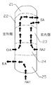
- the schematic diagram of the air flow path of fresh air introduction, internal circulation, and exhaust in an indoor air treatment apparatus is shown.
- FIG. 6 shows a schematic view of a first mounting scheme of an indoor air treatment device mounted on a wall by a first mounting surface.
- FIG. 6 shows a schematic view of a second mounting scheme for an indoor air treatment device mounted on a wall by a second mounting surface.
- attached on two walls is shown.
- the structural schematic of the back plate in a case is shown.
- a schematic configuration diagram of a mounting plate and a hook is shown.
- the structural schematic diagram which attached the back plate to the hook of a mounting plate is shown.
- It is a schematic diagram of a combination of an indoor air treatment device and a display panel in a modification.
- FIG. 9 is a schematic connection diagram of a display panel and a support rod in a modified example. It is the perspective view which looked at the air treatment equipment in the modification from the left rear side. It is a block diagram which looked at the airflow distribution chamber in the modification from the rear side upper part.
- FIG. 1a shows a front view of the indoor air treatment device as seen from the front.
- the direction outward which is perpendicular to the plane of the drawing, is the front direction
- the main exterior surface 131 is located on the front side surface of the cover body 13.
- the first end cap 11 is located at the upper end of the cover body 13 and the inward direction that is perpendicular to the paper surface of the drawing is the backward direction and the direction that is upward along the paper surface of the drawing is the upward direction.
- the second end cap 12 is located at the lower end of the cover body 13 with the downward direction along the paper surface of the drawing as the downward direction.
- the direction toward the right along the paper surface of the drawing is the right direction, and the first connecting surface 132 is connected to the right side of the main exterior surface 131.
- the direction toward the left along the paper surface of the drawing is the left direction, and the second connecting surface 133 is connected to the left side of the main exterior surface 131.
- the indoor air treatment device has a case 1 having a columnar structure.
- the case 1 includes a cylindrical cover body 13.
- the first end cap 11 is attached to the upper end of the cover body 13.
- the second end cap 12 is attached to the lower end of the cover body 13.
- the front side surface of the cover body 13 is the main exterior surface 131.
- the right side of the main exterior surface 131 is connected to the first connecting surface 132.
- the left side of the main exterior surface 131 is connected to the second connection surface 133.
- Information for example, temperature, humidity, PM2.5 concentration
- Operation mode, etc. is further attached with a display panel 139 for displaying.
- the indoor air treatment device includes an intake chamber 22, an air purification chamber 23, an air flow distribution chamber 24, and an exhaust chamber 25. Both the intake chamber 22 and the air flow distribution chamber 24 communicate with the air purification chamber 23.
- the intake chamber 22 is provided with an intake fan 31.
- An air purification assembly 32 is provided in the air purification chamber 23.
- An exhaust fan 33 is provided in the exhaust chamber 25.
- the intake chamber 22 has an air outlet 221/222 for communicating with the indoor space.
- the exhaust chamber 25 has a return air port 251 for communicating with the indoor space and an exhaust port 252a / 252b for communicating with the outdoor space.
- the case 1 is provided with the airflow distributor 14.
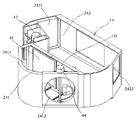
- the airflow distribution chamber 24 is provided in the airflow distribution body 14.
- the airflow distribution chamber 24 includes a new wind partition chamber 241 and a suction partition chamber 242.
- the new wind partition chamber 241 communicates with the air purification chamber 23.
- the new wind partition chamber 241 and the suction partition chamber 242 are communicated with each other by a communication port 2413.
- the fresh air partition chamber 241 has a first fresh air outlet 2411 and a second fresh air outlet 2412 for communicating with the outdoor space.
- the suction partition chamber 242 has a suction port 2421/2422 for communicating with the indoor space.
- the first new air vent 2411 is provided with a first valve plate 41 driven by the first drive mechanism 42.
- the second new air outlet 2412 is provided with a second valve plate 43 driven by the second drive mechanism 44.
- the indoor air treatment device can realize the following three basic operation patterns.
- the fresh air introduction operation pattern is a pattern that is individually performed in the air flow path from OA to SA in FIG. 4 to inhale fresh air from the outdoor space, purify it, and then transmit it to the indoor space.
- Air enters the airflow distribution chamber 24 through the first fresh air outlet 2411 or the second fresh air outlet 2412, and then flows into the air purification chamber 23.
- the intake chamber 22 draws in the purified air from the air purifying chamber 23 and blows it into the indoor space through the air blow ports 221/222.
- the internal circulation operation pattern is a pattern that is individually performed in the air flow path from RA2 to SA in FIG. 4 to suck in turbid air from the indoor space, purify the air, and then transmit the purified air to the indoor space.
- Air enters the airflow distribution chamber 24 through the suction ports 2421/2422 and then flows into the air purification chamber 23.
- the intake chamber 22 draws in the purified air from the air purifying chamber 23 and blows it into the indoor space through the air blow ports 221/222.
- ⁇ Operation pattern in which new air is introduced and internal circulation is performed at the same time The operation pattern in which the introduction of new air and the internal circulation are performed simultaneously is performed in the air flow path from OA to SA and the air flow path from RA2 to SA in FIG. 4 at the same time, and fresh air is taken from the outdoor space and purified. Is transmitted from the indoor space to the indoor space, and at the same time, turbid air is sucked from the indoor space, purified, and then transmitted to the indoor space.
- the outdoor air enters the air flow distribution chamber 24 from the first new air port 2411 or the second new air port 2412 and then flows into the air purification chamber 23, and at the same time, the indoor air flows from the suction port 2421/2422 to the air flow distribution chamber 24. After entering, it similarly flows to the air purification chamber 23.
- the intake chamber 22 draws in the purified air from the air purifying chamber 23 and blows it into the indoor space through the air blow ports 221/222.
- the indoor air treatment device can realize an exhaust operation pattern.
- the exhaust chamber 25 has a return air port 251 for communicating with the indoor space and an exhaust port 252a / 252b for communicating with the outdoor space.
- the exhaust fan 33 rotates, air enters the exhaust chamber 25 through the return air port 251 and then is discharged to the outdoor space through the exhaust ports 252a / 252b.
- the above three basic operation patterns can be performed individually. Further, the exhaust operation pattern can be performed individually (that is, it can be performed individually in the airflow path from RA1 to EA in FIG. 4), and the exhaust operation pattern is the above three basic operations. It can also be done at the same time as any one of the patterns.
- the exhaust chamber 25 is installed individually and does not communicate with the air flow distribution chamber 24, the air purification chamber 23, or the intake chamber 22. Therefore, in the indoor air treatment device, when the exhaust work is performed, the exhaust airflow does not collide with the airflow in the airflow distribution chamber 24, the air purification chamber 23, or the intake chamber 22, and the airflow is not turbulent or turbulent. Then, the internal circulation operation pattern and the new wind introduction operation pattern do not interfere with the normal operation. Moreover, according to the independent exhaust airflow path, it is possible to effectively prevent the airflow distribution chamber 24, the air purification chamber 23, or the intake chamber 22 from occupying the space, which is advantageous for securing the amount of new wind introduced. Yes, it is finally ensured that the air quality in the room satisfies the comfort requirements of the user.
- the indoor air treatment device When using the above indoor air treatment device, the indoor air treatment device is installed in the room, and the first new air outlet 2411 or the second new air outlet 2412 is communicated with the outdoor space.
- a fresh air introduction operation pattern, an internal circulation operation pattern, an operation pattern in which fresh air introduction and internal circulation are simultaneously performed, and a single exhaust operation pattern, or an exhaust operation pattern and any one of the above operation patterns Can be realized in combination with.
- the exhaust airflow paths are individually provided, there is no possibility that airflow turbulence or turbulence will occur due to collision with other airflow paths.
- the various operating patterns of the indoor air treatment device can be fitted and combined, thereby effectively treating the indoor air and improving the quality of the indoor air.
- one airflow distributor 14 is designed for the convenience of manufacturing.
- the airflow distribution chamber 24 is provided in the airflow distribution body 14.
- a partition wall 141 is provided between the fresh air partition chamber 241 and the suction partition chamber 242.
- the communication port 2413 is provided in the partition wall 141.
- the upper end of the new wind partition chamber 241 communicates with the air purification chamber 23, as can be seen with reference to FIGS. 2b, 2c, and 3b and 3d, in order to enable the airflow distribution chamber 24 to switch to the airflow path.
- the upper end of the suction partition chamber 242 does not communicate with the air purification chamber 23.
- the air that enters the fresh air partition chamber 241 from the fresh air inlet can directly enter the air purification chamber 23, but the air that enters the suction partition chamber 242 from the suction opening 2421/2422 can be sent through the communication opening 2413 to the fresh air partition chamber 2413. After entering the chamber 241 it enters the air purification chamber 23.
- the first valve plate 41 and the second valve plate 43 switching to the operation pattern of the indoor air treatment device is realized. be able to.
- Both the first drive mechanism 42 and the second drive mechanism 44 may be rotary motors.
- the opening degree of the first valve plate 41 or the second valve plate 43 can be controlled. This controls the magnitude of the air flow rate according to the actual demand for indoor air quality. In addition, it is also advantageous that the downsizing of the air treatment device is ensured.
- the first drive mechanism 42 and the second drive mechanism 44 operate the indoor air treatment device by driving the first valve plate 41 and the second valve plate 43, respectively. Control the pattern and air flow.
- the first new air outlet 2411 is provided with a first valve plate 41. ing.
- the first valve plate 41 is driven by the first drive mechanism 42, and is in a state where the first new air outlet 2411 is closed, a state where the communication port 2413 is closed, and between the first new air port 2411 and the communication port 2413. You can move to each of the states located in.
- a second valve plate 43 is provided at the second fresh air outlet 2412. The second valve plate 43 is driven by the second drive mechanism 44 to close or open the second fresh air outlet 2412, and the structure is simple.
- the communication port 2413 includes a first communication port 2413a and a second communication port 2413b provided in the partition wall.
- the first valve plate 41 is driven by the first drive mechanism 42 to close the first new air outlet 2411, the first communication port 2413a, and the first new air outlet 2411 and the first. It is possible to move to each of the states located between the communication ports 2413a.
- the second valve plate 43 is driven by the second drive mechanism 44 to close the second new air outlet 2412, the second communication port 2413b, and the second new air outlet 2412 and the second. , Which is located between the communication ports 2413b.
- the first communication port 2413a approaches the first valve plate 41 side
- the second communication port 2413b approaches the second valve plate 43 side. Since the structures on both the left and right sides of the airflow distributor 14 are basically symmetrical, it is easy to manufacture and install. Moreover, since both the first valve plate 41 and the second valve plate 43 rotate and move inside the fresh air partition chamber, they do not project from the outer wall of the airflow distributor. Therefore, the first valve plate 41 and the second valve plate 43 do not interfere with parts or walls outside the airflow distributor. Further, since the first valve plate 41 and the second valve plate 43 have the same motion mode, the second fresh air outlet 2412 is closed and fresh air is taken in through the first fresh air outlet 2411.
- the fresh air introduction operation pattern, the internal circulation operation pattern, and the fresh air of the indoor air treatment device are also obtained.
- the logic of controlling the operation pattern in which the introduction and the internal circulation are performed at the same time becomes the same. As described above, the control method is simple, and the user is less likely to be confused during use.
- the suction partition chamber 242 has two suction ports.
- One of the suction ports is the first suction port 2421.
- the outer surface of the case 1 further includes a first connecting surface 132 and a second connecting surface 133 extending along the longitudinal direction of the case 1.
- the first connecting surface 132 is connected to the right side of the main exterior surface 131.
- the second connection surface 133 is connected to the left side of the main exterior surface 131.
- the first suction port 2421 is exposed on the first connection surface 132.
- the second suction port 2422 is exposed on the second connection surface 133.
- a window grid 134 is further provided on the first connecting surface 132 and the second connecting surface 133.
- the airflow entering the first suction port 2421 and the second suction port 2422 becomes uniform. Further, it is possible to prevent the user's finger from getting inside the machine and coming into contact with the rotating member or the electric member, so that the use safety of the user is ensured.
- the overall outer shape of the above indoor air treatment device has a columnar structure.
- the intake chamber 22, the air purification chamber 23, the airflow distribution chamber 24, and the exhaust chamber 25 are all provided in the case 1 and the case 1 Are sequentially distributed from the first end to the second end.
- the overall columnar structure is easy to install and can be better integrated with the interior space.
- the indoor space processing device can be better integrated with the indoor space.
- the case 1 is provided with a first mounting surface 135 and a second mounting surface 136.
- the first new air vent 2411 is exposed from the first mounting surface 135.
- the second fresh air outlet 2412 is exposed from the second mounting surface 136.
- One exhaust port is exposed on each of the first mounting surface 135 and the second mounting surface 136.
- the exhaust port exposed from the first mounting surface 135 is the first exhaust port 252a.
- the exhaust port exposed from the second mounting surface 136 is the second exhaust port 252b.
- a first mounting interface 137 and a second mounting interface 138 are further provided on each of the first mounting surface 135 and the second mounting surface 136.
- the indoor air treatment device may be mounted by a first mounting interface 137 or a second mounting interface 138.
- the first mounting interface 137 or the second mounting interface 138 can be selected to mount the indoor air treatment device on the indoor wall 5. There are various mounting methods, and it is possible to satisfy the requirements of different mounting environments.
- the air purification assemble 32 is a columnar filter network as a preferred embodiment in order to adapt to the structural arrangement of the indoor air treatment apparatus.
- the outer structure of the air purification assembly 32 can be better matched with the air purification chamber 23, resulting in higher space utilization.
- the filter network can filter PM2.5 particulate matter in the air. Further, for example, by arranging some reactants capable of removing other pollutants such as formaldehyde in the filter network, harmful gaseous substances in the air in the indoor space or the outdoor space can be removed.
- one end of the air purification chamber 23 communicates with the intake chamber 22 and the other end of the air purification chamber 23 communicates with the airflow distribution chamber 24.
- the upper end of the air purification chamber 23 can be communicated with the intake chamber 22, and the lower end of the air purification chamber 23 can be communicated with the airflow distribution chamber 24.
- the air in the air flow distribution chamber 24 flows into the air purification chamber 23, is purified by the purification device, and then flows into the intake chamber 22. Eventually, the cleanliness of the air sent into the room is secured, and the user's request can be satisfied.
- the exhaust port 252a / 252b and the new air port 2411/2412 communicate with the outdoor space via a duct.
- the air flow at the fresh air outlets 2411/2412 and the exhaust ports 252a/252b does not disturb the air in the indoor space.
- the blower ports 221/222, the intake ports 2421/2422, and the return air port 251 are all located in the indoor space.
- the airflow port 221/222 is the upper part of the case 1 in order to prevent the airflows at the airflow port 221/222, the intake port 2421/2422, and the return air port 251 from being disturbed by each other.
- the intake ports 2421/2422 are located in the lower part of the case 1.
- the air outlets 221/222 and the intake ports 2421/2422 are far apart from each other, and the effect of mutual disturbance of the airflow at these two locations is weakened.
- the return air port 251 is provided on the end surface of the second end of the case 1.
- the return air port 251 is far away from the air outlet 221/222 and the intake port 2421/2422. Not only that, the direction of the return air port 251 is also different from that of the air outlet 221/222 and the intake port 2421/2422. Therefore, the airflow at the return air port 251 is unlikely to affect the airflow at the airflow port 221/222 or the intake port 2421/2422, and mutual interference between the airflows is avoided.
- the first end of the case 1 has a storage chamber 21 for accommodating the electric elements. Is further provided. Other electrical control elements such as a power supply and a controller may be installed in the accommodation chamber 21.
- the electrical element in the containment chamber 21 generates heat. If the accommodation chamber 21 is close to the new air outlet 2411/2412 or the exhaust port 252a / 252b, the temperature in the vicinity of the accommodation chamber 21 becomes low due to the low temperature air outside the room. However, moisture in the air in the housing chamber 21 condenses on the electric element to affect the insulation performance of the electric element, which increases the risk of the electric element failure.
- the indoor air treatment apparatus since the accommodation chamber 21 is separated from the new air outlet 2411/2412 and the exhaust ports 252a/252b, the risk of dew condensation in the accommodation chamber 21 is reduced, the operation reliability by the electric element is improved, and the indoor air treatment apparatus is improved. Is maintained to operate normally.
- an outdoor PM2.5 detection sensor is installed in the new wind partition chamber 241 and an indoor PM2.5 detection sensor is installed in the suction partition chamber 242. can do. Both the outdoor PM2.5 detection sensor and the indoor PM2.5 detection sensor are connected to the control device.
- the control device moves the first drive mechanism 42, the second drive mechanism 44, the intake fan 31, and the exhaust fan 33 based on the data detected by the outdoor PM2.5 detection sensor and the indoor PM2.5 detection sensor. Can be controlled. As a result, the indoor air is adjusted and the control accuracy is improved.
- the intake chamber 22 has two air outlets 221/222 in order to make the airflow sent from the air outlets 221/222 in the indoor air treatment device uniform.
- Each of the first connection surface 132 and the second connection surface 133 on both sides of the main exterior surface 131 is provided with one air outlet.
- the blower port on the first connection surface 132 is the first blower port 221.
- the air outlet on the second connection surface 133 is the second air outlet 222. Both the first blower opening 221 and the second blower opening 222 blow air into the indoor space.
- a turbofan may be used as the intake fan 31 in order to form the airflow sent from the first air outlet 221 and the second air outlet 222 into a surrounding airflow. As shown in FIG.
- the airflow delivered from the first air outlet 221 flows to one wall, and the airflow delivered from the second air outlet 222 flows to the other vertical wall.
- the two streams merge around the wall from opposite directions and are surrounded.
- Such fluid flow causes the airflow to be more evenly distributed throughout the room. And since it is not blown out by a person, the comfort of the person is significantly improved.
- the indoor air treatment device can better adapt to the indoor space.
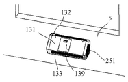
- the indoor air treatment device can be chosen to be mounted horizontally on the wall 5 between the window and the ground, as shown in Figure 5a.
- the first mounting surface 135 is attached to the wall 5.
- a duct communicating with the outdoor space is connected to the first new air port 2411 and the first exhaust port 252a on the first mounting surface 135.
- the main exterior surface 131 faces toward the ceiling so that a person can see the display panel in a plan view.
- the indoor air treatment device may be mounted horizontally on the wall 5 at a high position.
- the second mounting surface 136 is attached to the wall 5.
- a duct communicating with the outdoor space is connected to the second new air port 2412 and the second exhaust port 252b on the second mounting surface 136.
- the first mounting surface 135 faces the ceiling so that a person can view the display panel 139 from the bottom.
- the main exterior surface 131 faces the ground.
- the indoor air treatment device may be mounted perpendicular to the position of the wall angle.
- the first mounting surface 135 and the second mounting surface 136 can be attached to the two walls 5 at the wall corner, respectively.
- the angle between the two walls 5 at the wall angle is a right angle.
- the first mounting surface 135 and the second mounting surface 136 are attached to two vertical walls 5, respectively.
- the angle formed by the first mounting surface 135 and the second mounting surface 136 is a right angle.
- a duct communicating with the outdoor space is connected to the first new air port 2411 and the first exhaust port 252a on the first mounting surface 135.
- a duct communicating with the outdoor space may be connected to the second new air port 2412 and the second exhaust port 252b on the second mounting surface 136.
- the main exterior surface 131 faces horizontally.
- the first blower opening 221 and the second blower opening 222 respectively have two vertical walls. It will face the wall 5.
- the air sent out from the first air outlet 221 and the second air outlet 222 is formed in the surrounding airflow after being blocked by the two walls 5, respectively. As a result, the airflow becomes soft and evenly distributed.
- the indoor air treatment device may be mounted horizontally or vertically.
- the display panel 139 can be adapted for horizontal or vertical mounting of the air purification assembly 32, and the connection interface between the display panel 139 and the main exterior surface 131 can be installed in a 90 ° rotation compatible structure. .. After the display panel 139 and the main exterior surface 131 have been fitted and attached, the display panel 139 can be rotated 90 °, 180 °, or 270 ° along its location plane to refit with the connection interface on the main exterior surface 131. Can be connected. Then, by adjusting the angle of the display panel according to the mounting method of the air treatment device, it is possible to improve the convenience for the user to browse the display contents of the display panel.
- first mounting interface 137 and the second mounting interface 138 can be adapted for horizontal or vertical mounting of the air purification assembly 32. After the first mounting interface 137 or the second mounting interface 138 has been fitted in conformity with the connecting interface in the wall 5, the first mounting interface 137 or the second mounting interface 138 is mounted along its plane of occupancy 90. A rotation of °, 180° or 270° allows a refitting connection with the connection interface on the wall 5.
- a back plate 7 is connected to the case 1 of the indoor air treatment device in order to mount the indoor air treatment device on the wall 5.
- a mounting hole 71 is provided in the back plate 7.
- a mounting plate 6 is fixedly connected to the wall 5, and a hook 61 is fixed to the mounting plate 6.
- the back plate 7 is hooked on the hook 61 by the mounting hole 71. This makes it easier to hook the indoor air treatment device on the wall 5.
- the back plate 7, the mounting plate 6, and the hook 61 may be made of a sheet metal material. A connection by bolt connection or soldering may be adopted between the hook 61 and the mounting plate 6. In this case, the structure is simple and the installation is convenient.
- the indoor mounting device is mounted on the wall 5 by the first mounting surface 135.
- the first fresh air outlet 2411 and the first exhaust outlet 252a are attached to the wall 5 and are in a state of being shielded from the outdoor space.
- the first valve plate 41 and the second valve plate 43 are controlled by the following methods, respectively.
- the new wind introduction operation pattern will be described with reference to FIG. 3a.
- the new wind introduction operation pattern includes the following work steps. 1a) The first valve plate 41 is driven by the first drive mechanism 42 to move to a state in which the communication port 2413 is closed. Then, the suction partition chamber 242 and the new wind partition chamber 241 are shut off, and only the new wind partition chamber 241 communicates with the air purification chamber 23. 1b) The second valve plate 43 is driven by the second drive mechanism 44 to move to a state where the second new air outlet 2412 is opened, and the second new air outlet 2412 communicates with the outdoor space.
- the outdoor space communicates with the indoor space through the second new air outlet 2412, the new air partition chamber 241, the air purification chamber 23, the intake chamber 22, and the air outlet 221/222 in this order.
- the rotation of the intake fan 31 is started, and the power for airflow circulation is provided from the intake fan 31.
- fresh air in the outdoor space enters the air purification chamber 23 through the second fresh air outlet 2412 and the fresh air partition chamber 241 in order, and is purified by the air purification assembly 32, and then the intake chamber 22. Then, the air is blown into the indoor space through the blower ports 221/222 in order.
- the flow velocity of the air flowing in the indoor space can be adjusted, and further, the pressure of the air in the indoor space can be adjusted.
- the rotation speed of the intake fan 31 By increasing the rotation speed of the intake fan 31, a large amount of outdoor air is purified and then flows into the indoor space, and the air pressure in the indoor space becomes higher than the air pressure in the outdoor space.
- the indoor space is maintained at a positive pressure, turbid air is prevented from entering the room from the outside, and the cleanliness of the indoor air is ensured.
- the internal circulation operation pattern includes the following work steps.
- 2a) The first valve plate 41 is driven by the first drive mechanism 42 to move to a state in which the communication port 2413 is opened.
- the communication port 2413 connects the fresh air partition chamber 241 and the suction partition chamber 242. Then, the air in the indoor space passes through the intake port 2421/2422, the suction partition chamber 242, the communication port 2413, the new wind partition chamber 241 and the air purification chamber 23, the intake chamber 22, and the air outlet 221/222 in this order to enter the indoor space. You can enter again.
- 2b) The second valve plate 43 is driven by the second drive mechanism 44 to move to a state in which the second new air vent 2412 is closed.
- the second new air outlet 2412 is blocked from the outdoor space, and the first new air outlet 2411 is attached to the wall 5 to be shielded from the outdoor space. Therefore, air cannot enter the fresh air partition chamber 241 through the first fresh air outlet 2411 and the second fresh air outlet 2412, and only the air flowing from the suction partition chamber 242 can enter the fresh air partition chamber 241. it can. 2c)
- the rotation of the intake fan 31 is started, and the power for airflow circulation is provided from the intake fan 31. Under the drive of the intake fan 31, the air in the indoor space enters the air purification chamber 23 through the intake port 2421/2422, the suction partition chamber 242, the communication port 2413, and the new wind partition chamber 241 in this order, and is purified by the air purification assembly 32. After that, the air is returned to the indoor space through the intake chamber 22 and the air outlets 221 and 222 in that order.
- FIGS. 3c and 3d An operation pattern in which fresh air introduction and internal circulation are performed at the same time will be described with reference to FIGS. 3c and 3d.
- An operation pattern in which fresh air introduction and internal circulation are performed at the same time includes the following work steps.
- the communication port 2413 connects the fresh air partition chamber 241 and the suction partition chamber 242. Then, the air in the indoor space passes through the intake port 2421/2422, the suction partition chamber 242, the communication port 2413, the new wind partition chamber 241 and the air purification chamber 23, the intake chamber 22, and the air outlet 221/222 in this order to enter the indoor space. You can enter again.
- the second valve plate 43 is driven by the second drive mechanism 44 to move to a state where the second new air outlet 2412 is opened, and the second new air outlet 2412 communicates with the outdoor space. Then, the outdoor space passes through the second new air outlet 2412, the new air partition chamber 241, the air purification chamber 23, the intake chamber 22, and the air outlet 221/222 in this order, and communicates with the indoor space.
- 3c) The rotation of the intake fan 31 is started, and the power for airflow circulation is provided from the intake fan 31. Under the drive of the intake fan 31, the fresh air in the outdoor space enters the air purification chamber 23 through the second new air outlet 2412 and the new air partition chamber 241 in order, and after being purified by the air purification assembly 32, the air is taken in.
- the air is blown into the indoor space through the chamber 22 and the air outlets 221 and 222 in that order.
- the air in the indoor space enters the air purification chamber 23 in this order through the suction port 2421/2422, the suction partition chamber 242, the communication port 2413, and the new wind partition chamber 241.
- the air intake chamber 22 After purification by the air purification assembly 32, the air intake chamber 22 Then, the air is blown into the indoor space through the blower ports 221/222 in order. As a result, the quality of the air fed into the room finally satisfies the requirements of the user.
- the flow rate of the air entering the fresh air partition chamber 241 from the communication port 2413 can be adjusted, and further, the internal circulation air flow rate and the introduced fresh air.
- the magnitude of the flow rate can be adjusted.
- the size of the opening degree of the first valve plate 41 and the rotation speed of the intake fan 31 the size of the air pressure in the room can be adjusted. For example, by increasing the rotation speed of the intake fan 31, a large amount of outdoor air is purified and then flows into the indoor space, and the air pressure in the indoor space becomes larger than the air pressure in the outdoor space. Thereby, the indoor space is maintained at a positive pressure, turbid air is prevented from entering the room from the outside, and the cleanliness of the indoor air is secured.
- the exhaust operation pattern will be described.
- the indoor space and the outdoor space are communicated with each other through the return air port 251 and the second exhaust port 252b.
- the air in the indoor space is discharged to the outdoor space through the return air port 251, the exhaust fan 25, and the exhaust ports 252a/252b in order.
- the exhaust operation pattern may be performed individually, but among the above (A1) fresh air introduction operation pattern, (A2) internal circulation operation pattern, and (A3) operation mode in which fresh air introduction and internal circulation are performed at the same time. Any one may be performed at the same time.
- the pressure of the indoor air can be adjusted.
- the rotation speed of the exhaust fan 33 By increasing the rotation speed of the exhaust fan 33, more indoor air is discharged to the outside, and the pressure of the indoor air is reduced.
- the turbid air in the room is discharged to the outside of the room, and at the same time, the diffusion of the turbid air in the room to other rooms is suppressed.
- the indoor mounting device is mounted on the wall 5 by the second mounting surface 136.
- the second fresh air outlet 2412 and the second exhaust outlet 252b are attached to the wall 5 and are shut off from the outdoor space.
- the first valve plate 41 and the second valve plate 43 are controlled by the following methods, respectively.
- the new wind introduction operation pattern will be described with reference to FIG. 3e.
- the new wind introduction operation pattern includes the following work steps. Ia) The first valve plate 41 is driven by the first drive mechanism 42 to move to a state in which the communication port 2413 is closed. The first new air outlet 2411 communicates with the outdoor space. Then, the suction partition chamber 242 and the new wind partition chamber 241 are shut off, and only the new wind partition chamber 241 communicates with the air purification chamber 23. The outdoor space passes through the first new air outlet 2411, the new air partition chamber 241, the air purification chamber 23, the intake chamber 22, and the air outlet 221/222 in this order, and communicates with the indoor space.
- the internal circulation operation pattern includes the following working steps. IIa)
- the first valve plate 41 is driven by the first drive mechanism 42 to move to a state in which the first new air outlet 2411 is closed.
- the first new air outlet 2411 is blocked from the outdoor space, and the second new air outlet 2412 is attached to the wall 5 to be shielded from the outdoor space. Therefore, air cannot enter the new air partition chamber 241 from the first new air outlet 2411 or the second new air outlet 2412.
- the communication port 2413 is in an open position, the communication port 2413 communicates the suction partition chamber 242 and the new wind partition chamber 241, and the air in the indoor space is sucked into the suction port 2421/2422, the suction partition chamber 242, the communication port 2413, and the new wind partition.
- the air can be returned to the indoor space by sequentially passing through the ports 2421/2422, the suction partition chamber 242, the communication port 2413, the fresh air partition chamber 241, the air purification chamber 23, the air intake chamber 22, and the blower ports 221/222.
- IIIb) The rotation of the intake fan 31 is started, and the power for airflow circulation is provided from the intake fan 31. Under the drive of the intake fan 31, fresh air in the outdoor space enters the air purification chamber 23 through the first new air outlet 2411 and the new air partition chamber 241 in this order, and after being purified by the air purification assembly 32, the air is taken in. The air is blown into the indoor space through the chamber 32 and the air blow ports 221/222 in order.
- the air in the indoor space enters the air purifying chamber 23 through the suction ports 2421/2422, the suction partition chamber 242, the communication port 2413, and the fresh air partition chamber 241, in that order, and after being purified by the air purification assembly 32, the intake chamber 22. Then, the air is blown into the indoor space through the blower ports 221/222 in order.
- the magnitude of the opening degree of the first valve plate 41 By controlling the magnitude of the opening degree of the first valve plate 41, the magnitude of the flow rate of the introduced new wind and the magnitude of the air flow rate of the internal circulation can be adjusted.
- the opening degree of the first valve plate 41 and the rotation speed of the intake fan 31 it is possible to adjust the magnitude of the pressure of the air in the room. For example, by increasing the rotation speed of the intake fan 31, a large amount of outdoor air is purified and then flows into the indoor space, so that the pressure of air in the indoor space becomes higher than the pressure of air in the outdoor space. As a result, the indoor space is maintained at a positive pressure, turbid air from the outside is prevented from entering the room, and the cleanliness of the indoor air is ensured.
- exhaust operation pattern may be performed individually, any one of the above (B1) fresh air introduction operation pattern, (B2) internal circulation operation pattern, and (B3) operation pattern in which fresh air introduction and internal circulation are performed simultaneously Or one can be done at the same time.
- the pressure of the indoor air can be adjusted.
- the rotation speed of the exhaust fan 33 By increasing the rotation speed of the exhaust fan 33, more indoor air is discharged to the outside, and the pressure of the indoor air is reduced. As a result, the turbid air in the room is discharged to the outside, and at the same time, the diffusion of the turbid air in the room to other rooms is suppressed.
- the indoor air treatment device can realize fusion of a plurality of types of operation patterns, and various operation patterns can be combined appropriately. .. Thereby, the indoor air can be effectively treated and the quality of the indoor air can be improved. Moreover, since the exhaust airflow paths are individually provided, the airflow turbulence and the turbulent flow do not occur due to collision with other airflow paths. Therefore, the operation performance of the indoor air treatment device is further improved, and the user's sensation is further improved.
- the indoor air treatment device may be mounted by a plurality of types of mounting methods. Appropriate mounting methods can be selected according to different indoor mounting environments, and can be better adapted to the layout of the indoor space.
- the indoor air treatment device may be mounted on a wall at a low position, may be mounted on a wall at a high position, or may be mounted according to the position of the wall angle.
- the opening of the first new air outlet, the second new air outlet, and the communication port is finely controlled by using the first valve plate and the second valve plate. , Achieve the purpose of air flow control, and realize the switching between the new air introduction operation pattern, the internal circulation operation pattern, the operation pattern in which the new air introduction and internal circulation are performed simultaneously, and the exhaust work pattern is performed individually, or , May be performed simultaneously with other work patterns.
- the control system is simplified, the structure and layout are rational, the volume is small, and the indoor space is saved.
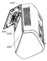
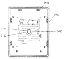
- This indoor air treatment device includes a housing 3002 and a display panel 3001. At least two sets of engaging portions 3011 are provided on the back of the display panel 3001. The rotation angle of the two adjacent sets of engaging portions 3011 with respect to the center of the display panel 3001 is 90 °.
- the display panel 3001 is mounted on the housing 3002 by at least one set of two sets of engaging portions 3011.
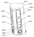
- a housing 4001 shown in FIGS. 10 and 11 may be adopted. On the side plate of the housing 4001, two fresh air openings 4111/4121 for communicating with the outside of the room are opened.
- Both of the two fresh air inlets 4111/4121 may be installed on the first mounting plate 4011 or the second mounting plate 4012.
- the two fresh air inlets 4111/4121 may be installed on the first mounting plate 4011 and the second mounting plate 4012, respectively.
- the housing 4001 between the two new air vents is provided with one air detecting means 4005. Therefore, the air detection unit 4005 can detect the introduced fresh air regardless of which fresh air port has introduced the fresh air. As a result, the control accuracy of the air treatment equipment can be improved.
- the air detection means 4005 is preferably a PM2.5 detection sensor for detecting the PM2.5 concentration of outdoor air.
- the first fresh air inlet 4111 is provided on the first mounting plate 4011 in the process of concrete implementation.
- a second fresh air port 4121 is provided on the second mounting plate 4012. The centers of the two fresh air outlets are located on the same horizontal line.
- the air detecting means 4005 is provided inside the connection portion between the first mounting plate 4011 and the second mounting plate 4012.
- the indoor air treatment device described above solves various deficiencies existing in the prior art and has high industrial utility value.
Landscapes
- Engineering & Computer Science (AREA)
- Chemical & Material Sciences (AREA)
- Combustion & Propulsion (AREA)
- Mechanical Engineering (AREA)
- General Engineering & Computer Science (AREA)
- Ventilation (AREA)
Priority Applications (1)
| Application Number | Priority Date | Filing Date | Title |
|---|---|---|---|
| JP2021504055A JP7174296B2 (ja) | 2019-03-01 | 2020-02-28 | 室内空気処理装置及びその作動方法 |
Applications Claiming Priority (6)
| Application Number | Priority Date | Filing Date | Title |
|---|---|---|---|
| CN201910157077.2A CN111637548B (zh) | 2019-03-01 | 2019-03-01 | 室内空气处理装置及其工作方法 |
| CN201910157077.2 | 2019-03-01 | ||
| CN201920813599.9 | 2019-05-31 | ||
| CN201920813599.9U CN210425413U (zh) | 2019-05-31 | 2019-05-31 | 一种空气处理设备 |
| CN201920813589.5U CN210740621U (zh) | 2019-05-31 | 2019-05-31 | 一种空气处理装置 |
| CN201920813589.5 | 2019-05-31 |
Publications (1)
| Publication Number | Publication Date |
|---|---|
| WO2020179688A1 true WO2020179688A1 (ja) | 2020-09-10 |
Family
ID=72337833
Family Applications (1)
| Application Number | Title | Priority Date | Filing Date |
|---|---|---|---|
| PCT/JP2020/008393 Ceased WO2020179688A1 (ja) | 2019-03-01 | 2020-02-28 | 室内空気処理装置及びその作動方法 |
Country Status (2)
| Country | Link |
|---|---|
| JP (1) | JP7174296B2 (https=) |
| WO (1) | WO2020179688A1 (https=) |
Cited By (7)
| Publication number | Priority date | Publication date | Assignee | Title |
|---|---|---|---|---|
| CN114183839A (zh) * | 2020-09-15 | 2022-03-15 | 广东美的制冷设备有限公司 | 空气处理装置、空调室内机和空调器 |
| CN114396653A (zh) * | 2021-12-04 | 2022-04-26 | 徐州新风空调设备有限公司 | 具有换新风功能的空调机 |
| CN114659205A (zh) * | 2022-04-08 | 2022-06-24 | 安徽兴鼎建设有限公司 | 一种大跨度厂房新风系统及施工方法 |
| CN115704585A (zh) * | 2021-08-17 | 2023-02-17 | 宁波方太厨具有限公司 | 具有新风功能的空气净化系统及工作方法 |
| CN116678037A (zh) * | 2023-07-14 | 2023-09-01 | 珠海格力节能环保制冷技术研究中心有限公司 | 换气部件及具有其的空调 |
| WO2024021633A1 (zh) * | 2022-07-29 | 2024-02-01 | 宁波奥克斯电气股份有限公司 | 新风模块和空调器 |
| CN120274355A (zh) * | 2025-04-28 | 2025-07-08 | 东台有康科技有限公司 | 一种装配式可变操控调节的洁净室隔间吊顶设备 |
Families Citing this family (5)
| Publication number | Priority date | Publication date | Assignee | Title |
|---|---|---|---|---|
| CN113915718A (zh) * | 2021-10-31 | 2022-01-11 | 爱普瑞环保科技(广东)有限公司 | 一种可内外循环消毒杀菌新风净化的系统 |
| CN115076835B (zh) * | 2022-05-31 | 2025-12-19 | 青岛海尔空调器有限总公司 | 一种空气净化装置 |
| CN116085907B (zh) * | 2023-02-20 | 2023-07-28 | 浙江海致建设有限公司 | 一种建筑室内空气流通循环调节装置 |
| CN119436277B (zh) * | 2023-07-31 | 2025-11-18 | 青岛海尔空调器有限总公司 | 新风模块、空调器柜机和空调器 |
| CN119436351B (zh) * | 2023-07-31 | 2025-11-18 | 青岛海尔空调器有限总公司 | 新风模块及空调器 |
Citations (4)
| Publication number | Priority date | Publication date | Assignee | Title |
|---|---|---|---|---|
| JP2001248865A (ja) * | 2000-03-08 | 2001-09-14 | Midori Anzen Co Ltd | 換気機能付空気清浄装置 |
| JP2010043854A (ja) * | 2009-09-29 | 2010-02-25 | Max Co Ltd | 空気清浄機 |
| WO2013153995A1 (ja) * | 2012-04-09 | 2013-10-17 | バルミューダ株式会社 | 空気清浄装置 |
| JP2018179490A (ja) * | 2017-04-11 | 2018-11-15 | 大連理工大学Dalian University of Technology | 空気清浄機能を備えた窓及びその換気方法 |
-
2020
- 2020-02-28 WO PCT/JP2020/008393 patent/WO2020179688A1/ja not_active Ceased
- 2020-02-28 JP JP2021504055A patent/JP7174296B2/ja active Active
Patent Citations (4)
| Publication number | Priority date | Publication date | Assignee | Title |
|---|---|---|---|---|
| JP2001248865A (ja) * | 2000-03-08 | 2001-09-14 | Midori Anzen Co Ltd | 換気機能付空気清浄装置 |
| JP2010043854A (ja) * | 2009-09-29 | 2010-02-25 | Max Co Ltd | 空気清浄機 |
| WO2013153995A1 (ja) * | 2012-04-09 | 2013-10-17 | バルミューダ株式会社 | 空気清浄装置 |
| JP2018179490A (ja) * | 2017-04-11 | 2018-11-15 | 大連理工大学Dalian University of Technology | 空気清浄機能を備えた窓及びその換気方法 |
Cited By (8)
| Publication number | Priority date | Publication date | Assignee | Title |
|---|---|---|---|---|
| CN114183839A (zh) * | 2020-09-15 | 2022-03-15 | 广东美的制冷设备有限公司 | 空气处理装置、空调室内机和空调器 |
| CN115704585A (zh) * | 2021-08-17 | 2023-02-17 | 宁波方太厨具有限公司 | 具有新风功能的空气净化系统及工作方法 |
| CN114396653A (zh) * | 2021-12-04 | 2022-04-26 | 徐州新风空调设备有限公司 | 具有换新风功能的空调机 |
| CN114659205A (zh) * | 2022-04-08 | 2022-06-24 | 安徽兴鼎建设有限公司 | 一种大跨度厂房新风系统及施工方法 |
| CN114659205B (zh) * | 2022-04-08 | 2024-05-31 | 安徽兴鼎建设有限公司 | 一种大跨度厂房新风系统及施工方法 |
| WO2024021633A1 (zh) * | 2022-07-29 | 2024-02-01 | 宁波奥克斯电气股份有限公司 | 新风模块和空调器 |
| CN116678037A (zh) * | 2023-07-14 | 2023-09-01 | 珠海格力节能环保制冷技术研究中心有限公司 | 换气部件及具有其的空调 |
| CN120274355A (zh) * | 2025-04-28 | 2025-07-08 | 东台有康科技有限公司 | 一种装配式可变操控调节的洁净室隔间吊顶设备 |
Also Published As
| Publication number | Publication date |
|---|---|
| JP7174296B2 (ja) | 2022-11-17 |
| JPWO2020179688A1 (https=) | 2020-09-10 |
Similar Documents
| Publication | Publication Date | Title |
|---|---|---|
| WO2020179688A1 (ja) | 室内空気処理装置及びその作動方法 | |
| JP7219409B2 (ja) | 空気浄化及び通風装置 | |
| CN205279278U (zh) | 智能净化柜式新风换气机 | |
| KR100686024B1 (ko) | 공기청정 겸용 환기시스템 및 이를 이용한 운전방법 | |
| CN105202646B (zh) | 智能净化柜式新风换气机 | |
| KR102026341B1 (ko) | 폐열회수형 환기장치 및 이의 제어방법 | |
| KR102320677B1 (ko) | 공기조화기 | |
| CN107202396A (zh) | 一种双循环式新风系统和新风机 | |
| CN112303788B (zh) | 新风系统的湿度控制方法 | |
| KR20050123308A (ko) | 공기청정 겸용 환기시스템 | |
| CN107366970A (zh) | 空气处理模块及空调器 | |
| CN111174344A (zh) | 一种富氧新风系统 | |
| KR102142196B1 (ko) | 공기 청정기 및 이를 갖는 실내 공기 정화 시스템 | |
| CN111637548B (zh) | 室内空气处理装置及其工作方法 | |
| JP2018132246A (ja) | 空気清浄機およびそれを用いた空気清浄システム | |
| KR100539568B1 (ko) | 공기청정겸용 환기시스템 | |
| CN205980056U (zh) | 一种新风机和空气净化机一体机 | |
| CN105650798B (zh) | 具有新风功能的换气装置 | |
| CN106352421B (zh) | 一种新风装置 | |
| CN111637551B (zh) | 空气处理装置 | |
| CN203561034U (zh) | 一种地送风管路出风口送风盒 | |
| KR20060091441A (ko) | 공기청정겸용 환기시스템 | |
| CN107327909A (zh) | 一种新风、净化一体机 | |
| CN216522029U (zh) | 空气处理装置和空调器 | |
| CN207455836U (zh) | 一种净化机 |
Legal Events
| Date | Code | Title | Description |
|---|---|---|---|
| 121 | Ep: the epo has been informed by wipo that ep was designated in this application |
Ref document number: 20766151 Country of ref document: EP Kind code of ref document: A1 |
|
| ENP | Entry into the national phase |
Ref document number: 2021504055 Country of ref document: JP Kind code of ref document: A |
|
| NENP | Non-entry into the national phase |
Ref country code: DE |
|
| 122 | Ep: pct application non-entry in european phase |
Ref document number: 20766151 Country of ref document: EP Kind code of ref document: A1 |