WO2020179195A1 - 制御装置、制御方法及び非一時的なコンピュータ可読媒体 - Google Patents
制御装置、制御方法及び非一時的なコンピュータ可読媒体 Download PDFInfo
- Publication number
- WO2020179195A1 WO2020179195A1 PCT/JP2019/050078 JP2019050078W WO2020179195A1 WO 2020179195 A1 WO2020179195 A1 WO 2020179195A1 JP 2019050078 W JP2019050078 W JP 2019050078W WO 2020179195 A1 WO2020179195 A1 WO 2020179195A1
- Authority
- WO
- WIPO (PCT)
- Prior art keywords
- route
- unmanned aerial
- control device
- aerial vehicle
- schedule
- Prior art date
- Legal status (The legal status is an assumption and is not a legal conclusion. Google has not performed a legal analysis and makes no representation as to the accuracy of the status listed.)
- Ceased
Links
Images





Classifications
-
- B—PERFORMING OPERATIONS; TRANSPORTING
- B65—CONVEYING; PACKING; STORING; HANDLING THIN OR FILAMENTARY MATERIAL
- B65G—TRANSPORT OR STORAGE DEVICES, e.g. CONVEYORS FOR LOADING OR TIPPING, SHOP CONVEYOR SYSTEMS OR PNEUMATIC TUBE CONVEYORS
- B65G61/00—Use of pick-up or transfer devices or of manipulators for stacking or de-stacking articles not otherwise provided for
-
- B—PERFORMING OPERATIONS; TRANSPORTING
- B64—AIRCRAFT; AVIATION; COSMONAUTICS
- B64U—UNMANNED AERIAL VEHICLES [UAV]; EQUIPMENT THEREFOR
- B64U2101/00—UAVs specially adapted for particular uses or applications
- B64U2101/60—UAVs specially adapted for particular uses or applications for transporting passengers; for transporting goods other than weapons
Definitions
- the present invention relates to a control device, a control method, and a non-transitory computer-readable medium, for example, a control device, a control method, and a non-transitory computer-readable medium for an unmanned air vehicle that transports a load.
- an unmanned aerial vehicle that is, an unmanned aerial vehicle that fly three-dimensionally in space by autonomous or remote control without a person boarding, so-called drone, etc.
- Logistics is one of the methods of using air vehicles. At present, such an unmanned aerial vehicle is being tested and studied for its application as a next-generation delivery machine, and is being developed for commercial use in the field of logistics.
- Patent Document 1 describes a transportation system in which an unmanned aerial vehicle is charged at a relay station in a transportation system that uses an unmanned aerial vehicle that flies while mounting a container for storing luggage to be transported.
- a control device includes a communication unit that obtains information on a departure point and a destination of a cargo, and a management unit that manages a route and a schedule of an unmanned air vehicle that transports the cargo, and the management unit is the A transportation route is set based on the origin and destination of the cargo, the management unit assigns the transportation route to the unmanned aerial vehicle in units of sections, sets the schedule of the unmanned aerial vehicle, and the management unit The route and schedule of the unmanned aerial vehicle are assigned to the transportation route on a section basis, and the communication unit transmits the route and the set schedule on a section basis to the unmanned vehicle.
- a control method is to obtain information on a starting point and a destination of a cargo, set a transportation route based on the starting point and the destination of the cargo, and set the transportation route in units of sections to the unmanned air vehicle.
- the schedule of the unmanned aerial vehicle is set, and the route and schedule assigned in the section unit are transmitted to the unmanned aerial vehicle.
- the non-transitory computer-readable medium of one embodiment sets a transportation route in the control device based on the step of obtaining information on the departure point and destination of the cargo and the control device based on the departure point and destination of the cargo.
- the transportation route is assigned to the unmanned aviation vehicle in section units, and the schedule of the unmanned aviation vehicle is set.
- the route and schedule assigned in section units are assigned. The computer was made to perform the step of transmitting to the unmanned aircraft.
- control device the control method, and the non-transitory computer-readable medium of the present invention, it is possible to transport a load by a plurality of unmanned aerial vehicles over a distance over which the unmanned aerial vehicles can fly.
- FIG. 3 is a block diagram showing a schematic configuration of a control device according to the first exemplary embodiment. It is a figure which shows schematic structure of the transportation system concerning Embodiment 2.
- 6 is a block diagram showing a schematic configuration of a control device according to a second embodiment.
- FIG. It is a figure which shows an example of the route of a high altitude route. It is a figure which shows an example of the route of a low altitude route. It is a top view which shows an example of the luggage collection center of the transportation system of Embodiment 2.
- 9 is a flowchart showing an example of a normal system flow of the control device of the second embodiment. 9 is a flowchart showing an example of a load receiving process of the control device according to the second embodiment.
- 9 is a flowchart showing an example of a route setting process of the control device according to the second embodiment. It is a flowchart which shows an example of the process of assigning an unmanned aerial vehicle by the control device of Embodiment 2. It is a flowchart which shows an example of the processing of the unmanned aerial vehicle of the departure place by the control device of Embodiment 2. It is a flowchart which shows an example of the processing of the unmanned aerial vehicle of the relay point by the control device of Embodiment 2. It is a flowchart which shows an example of the processing of the unmanned aerial vehicle of a destination by the control device of Embodiment 2. 9 is a flowchart showing an example of processing performed by the control device according to the second embodiment when an abnormality occurs in an unmanned air vehicle.
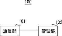
- FIG. 1 is a block diagram showing a schematic configuration of a control device according to the first embodiment.
- the control device 100 includes a communication unit 101 and a management unit 102.
- the control device 100 is a control device used in a system for transporting a cargo by an unmanned aerial vehicle.
- the communication unit 101 obtains information on the origin and destination of the cargo.
- the communication unit 101 also transmits the route assigned by the management unit 102 in units of sections and the set schedule to the unmanned air vehicle.
- the communication unit 101 obtains information on the origin and destination of the cargo via the network.
- the communication unit 101 obtains information on the departure point and destination of the cargo from the terminal that has received the request for transportation of the cargo via the network.
- the communication unit 101 transmits the assigned route and the set schedule to the unmanned air vehicle via the network.
- the communication unit 101 transmits the assigned route and the set schedule from the wireless base station connected to the network to the unmanned air vehicle.
- the management unit 102 manages the route and schedule of the unmanned aerial vehicle that transports the cargo. In addition, the management unit 102 sets a transportation route based on the departure point and the destination of the cargo. Then, the management unit 102 allocates the transportation route to the unmanned aerial vehicle in units of sections, and sets the schedule of the unmanned aerial vehicle. The management unit 102 allocates the route and schedule of the unmanned aerial vehicle for each section of the transportation route. Then, the management unit 102 transmits the allocation to the communication unit 101.
- the management unit 102 may be a logical operation device including a CPU (Central Processing Unit) and a memory.
- control device of the first embodiment by relaying the cargo with a plurality of unmanned air vehicles, it is possible to transport a distance exceeding the flight distance of the unmanned air vehicles.
- FIG. 2 is a diagram showing a schematic configuration of the transportation system according to the second embodiment. 2, the same components as those in FIG. 1 are designated by the same reference numerals, and the description thereof will be omitted.
- the transportation system 200 includes a control device 100, a network 201, a terminal 202, unmanned air vehicles 203-1 to 203-n, and luggage collection points 204-1 to 204-m.
- n and m are positive integers.
- n and m may have the same value. Further, n and m may have different values.
- the control device 100 is the control device described in the first embodiment.
- the control device 100 obtains information on the departure point and the destination of the cargo input to the terminal 202 via the network 201. Further, the control device 100 transmits the assigned route and the set schedule to the unmanned aerial vehicles 203-1 to 203-n via the network 201.
- the network 201 is a communication network that connects the control device 100, the terminal 202, the unmanned aerial vehicles 203-1 to 203-n, and the luggage collection points 204-1 to 204-m-1.
- the network 201 is a wired, wireless network or a network that combines wired and wireless networks.
- the terminal 202 is a terminal that receives information on the departure point and destination of the cargo to be transported.
- the terminal 202 transmits the information about the starting point and the destination of the cargo to be transported, which has been input, to the control device 100 via the network 201.
- the terminal 202 may be provided in each of the luggage collection points 204-1 to 204-m-1.
- Unmanned aerial vehicles 203-1 to 203-n are aircraft that transport luggage.
- the unmanned aerial vehicles 203-1 to 203-n may be drones capable of gripping luggage.
- the unmanned aerial vehicles 203-1 to 203-n each include a communication circuit that connects to the network 201 in a wired or wireless manner. Then, the unmanned aerial vehicles 203-1 to 203-n receive the route and schedule information from the control device 100.
- the unmanned aerial vehicles 203-1 to 203-n fly according to the received route and schedule information.
- the unmanned aerial vehicles 203-1 to 203-n preferably have a positioning device in order to fly on the received route. Further, the unmanned aerial vehicles 203-1 to 203-n may have a wireless reception circuit that receives a beacon (wireless beacon) in order to fly on the received route.
- a beacon wireless beacon
- Luggage collection points 204-1 to 204-m are bases for delivering luggage to be transported to unmanned aerial vehicles 203-1 to 203-n.
- the luggage collection points 204-1 to 204-m are also relay points for relay transportation.
- the transportation system 200 of the second embodiment performs relay transportation. For example, when the luggage is transported from the luggage collection point 204-1 to the destination of the luggage collection point 204-m, the unmanned air vehicle 203-1 moves from the luggage collection point 204-1 to the luggage collection point 204-2. Transport the luggage to 2. Then, the unmanned aerial vehicle 203-2 (not shown) transports the luggage from the luggage collection point 204-2 to the luggage collection point 204-3 (not shown). Then, the unmanned aerial vehicle 203-n transports the luggage from the luggage collection point 204-m-1 (not shown) to the luggage collection point 204-m.
- a plurality of unmanned aerial vehicles 203-1 to 203-n relay transportation of the luggage in units of sections, so that the luggage can be transported from the origin to the destination.
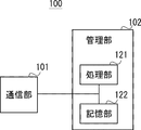
- FIG. 3 is a block diagram showing a schematic configuration of the control device according to the second embodiment.
- the control device 100 includes a communication unit 101 and a management unit 102.
- the same configurations as those in FIG. 1 are assigned the same numbers, and the description thereof will be omitted.
- the management unit 102 includes a processing unit 121 and a storage unit 122.
- the processing unit 121 executes the processing of each flow described below.
- the processing unit 121 may be configured to have a CPU (Central Processing Unit) and a memory. Further, the processing unit 121 may be configured to include an FPGA (Field-Programmable Gate Array) and an ASIC (Application Specific Integrated Circuit).
- CPU Central Processing Unit
- FPGA Field-Programmable Gate Array
- ASIC Application Specific Integrated Circuit
- the storage unit 122 stores information on each database described below. Further, the storage unit 122 outputs the stored information in response to the request of the processing unit 121. Further, the storage unit 122 stores or updates information according to the writing of the processing unit 121.
- the storage unit 122 may be at least one or a combination of a semiconductor memory, a magnetic memory, a magnetic storage device, and a photomagnetic storage device.
- the storage unit 122 stores, in the invoice database, items such as a destination (destination), a client, a package (size, mass), a product name, and a delivery date and time in association with each other. Further, the storage unit 122 stores the luggage collection place identification number, the vacant loading port number, the vacant parking port number, the vacant box number, and the stored luggage items in association with each other in the luggage collection database. Further, the storage unit 122 uses the route database to store route numbers, luggage collection numbers, loading port numbers, parking port numbers, unmanned air vehicle identification numbers, arrival prediction times, estimated takeoff times, and unmanned air vehicle standby information. The items are stored in association with each other. Further, the storage unit 122 stores the items of the route number, the drone identification number, the scheduled route entry time, and the scheduled route exit time in association with each other in the operation database.
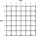
- FIG. 4 and 5 are diagrams showing an example of a route in the transportation system according to the second embodiment.
- FIG. 4 is a diagram showing an example of a high altitude route.
- FIG. 5 is a diagram showing an example of the route of the low altitude route.
- the high altitude means a route whose altitude (for example, the ground altitude) is higher than a predetermined level
- the low altitude means a route whose altitude is a predetermined low level.
- Fig. 4 and Fig. 5 the directions are opposite on routes with the same latitude or the same longitude.
- the route of FIG. 4 is defined as the forward direction and the route of FIG. 5 is defined as the reverse direction
- the altitudes in the same latitude and longitude are different in the forward direction and the backward direction. Therefore, even if the unmanned aerial vehicle is flying in the forward and reverse directions at the same time, it will not collide.
- the management unit 102 of the control device 100 sets the route of the unmanned air vehicle so that the route having the same latitude and longitude has different altitudes in the forward direction and the backward direction.
- the management unit assigns the route of the unmanned aerial vehicle that is in charge of transporting the cargo by altitude, so that the unmanned aerial vehicle does not collide.
- the management unit assigns routes of different altitudes in the forward direction and the reverse direction in the route having the same latitude and longitude to the transportation in the unit of section, so that the unmanned air vehicle can operate. Collisions do not occur even when flying forward and backward at the same time.
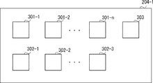
- FIG. 6 is a top view showing an example of a luggage collection point of the transportation system of the second embodiment.
- Luggage collection points 204-1 to 204-m have a flat surface on the upper surface where unmanned aerial vehicles can land and stand by. Then, as shown in FIG. 6, the loading port 301-1 to 301-n, the parking port 302-1 to 302-n, and the storage port 303 are provided on the upper surface.
- Loading ports 301-1 to 301-n are ports for unmanned air vehicles to unload cargo.
- the loading ports 301-1 to 301-n are ports on which an unmanned aerial vehicle loads luggage.
- Parking ports 302-1 to 302-n are ports where unmanned aerial vehicles with unloaded luggage are parked. It is desirable that the parking ports 302-1 to 302-n be used to refuel or charge the battery of the unmanned aerial vehicle.
- the storage port 303 is a port for storing luggage when it is a destination.
- the luggage may be stored in the large-sized parcel delivery box BOX from the storage port 303 (specifically, from the storage port 303 to the large-sized parcel delivery luggage using a transport mechanism such as an automatic warehouse or a three-dimensional parking lot of an automobile. You may carry your luggage to the integrated BOX)
- Unmanned aerial vehicles 203-1 to 203-n will relay the luggage at the above-mentioned luggage collection points 204-1 to 204-m. Specifically, the relay is performed according to the following procedure.
- the unmanned aerial vehicle 203-1 unloads the reserved loading port 301-1. Next, the unmanned aerial vehicle 203-1 moves to the parking port 302-1 and lands.
- the subsequent unmanned aerial vehicle 203-2 which was on standby, moves to the loading port 301-1, picks up the luggage, and starts toward the next luggage collection point 204-2.
- unmanned aerial vehicles 203-3 to 203-n relay transport from the luggage collection point 204-2 to the luggage collection point 204-m.
- the unmanned aerial vehicle 203-n unloads the luggage at the storage port.
- FIG. 7 is a flowchart showing an example of a normal system flow of the control device according to the second embodiment.
- step S401 of FIG. 7 the baggage collection point 204-1 receives the package from the client, and the terminal 202 receives the information on the transportation destination of the package. Then, the process proceeds to step S402. In step S402, the route for transporting the luggage is set by the control device 100, and the process proceeds to step S403.
- step S403 the control device 100 assigns an unmanned air vehicle for each section of the route for transporting the luggage, and the process proceeds to step S404.
- step S404 the control device 100 controls the unmanned air vehicle at the departure place, and the process proceeds to step S405.
- step S405 the control device 100 controls the unmanned aerial vehicle at the relay location, and the process proceeds to step S406.
- step S406 the control device 100 controls the unmanned air vehicle at the destination, and the luggage arrives at the destination.
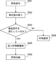
- FIG. 8 is a flowchart showing an example of a load receiving process of the control device according to the second embodiment.
- step S501 of FIG. 8 the terminal 202 accepts transportation of luggage. Then, the process proceeds to step S502. In step S502, the terminal 202 reads the tag of the luggage, and the process proceeds to step S503.
- step S503 the terminal 202 or the control device 100 determines whether or not the package satisfies the transportation conditions.
- the transport conditions may be, for example, that the weight and size of the package are within the transportable range, and that the destination is within the scope of the transport service. If the package does not satisfy the transportation condition, the process proceeds to step S504, and if the package satisfies the transportation condition, the process proceeds to step S505.
- step S504 the package is returned, and the process ends.
- step S505 invoice information is registered in the database in the control device 100, and the process proceeds to step S506.
- the control device 100 collectively manages items such as a delivery destination (destination), a client, a package (size, mass), a product name, and a delivery date and time in the invoice database as invoice information.
- step S506 the luggage is stored in the luggage collection point 204-1 and the luggage is ready to be loaded on the unmanned aerial vehicle.
- FIG. 9 is a flowchart showing an example of the route setting process of the control device according to the second embodiment.
- step S601 of FIG. 9 the departure point, the destination, and the delivery time are set by referring to the invoice database, and the process proceeds to step S602. Specifically, in step S602, the position of the departure baggage collection point 204-1 is set as the departure point, and the position of the target baggage collection point 204-m is set as the destination.
- step S602 the process of reserving the route to all the relay luggage collection points on the route is performed.
- the process of step S602 is looped along the route from 1 to m-1 of the luggage collection point 204 on the route.
- items such as a route number, a baggage collection site number, a loading port number, a parking port number, an estimated arrival time, and an estimated take-off time are collectively managed in the route database.
- the control device 100 determines whether or not the route can be reserved for each section by referring to this route database.
- a newly reserved route is written in the route database for each section.
- the newly reserved baggage collection point is written in the baggage collection point database.
- the baggage depot database has items such as a baggage depot identification number, an empty cargo storage port number, an empty parking port number, an empty box number, and a stored baggage.
- FIG. 10 is a flowchart showing an example of a process in which the control device of the second embodiment assigns an unmanned air vehicle.
- step S701 of FIG. 10 the control device 100 performs a process of acquiring information of the unmanned air vehicle waiting. Then, the process proceeds to step S702.
- the control device 100 acquires information on the waiting unmanned aerial vehicle by referring to this route database.
- the route database also includes items for unmanned aerial vehicle standby information. Further, the control device 100 acquires the information of the unmanned aerial vehicle that is waiting by referring to the items of the route number, the baggage collection number, the estimated arrival time, and the scheduled take-off time of the unmanned aerial vehicle in the route database. To do.
- step S702 the control device 100 determines whether or not an empty unmanned aerial vehicle (that is, an unmanned aerial vehicle not reserved for baggage transportation) is parked at the reserved baggage collection point. If the vacant unmanned air vehicle is parked at the reserved baggage collection point, the process proceeds to step S703. If the vacant unmanned air vehicle is not parked at the reserved baggage collection point, the step proceeds to step S704. move on.
- an empty unmanned aerial vehicle that is, an unmanned aerial vehicle not reserved for baggage transportation
- step S703 the control device 100 performs a process of reserving an empty unmanned air vehicle.
- the control device 100 writes information on the unmanned air vehicle to be reserved in this route database.
- the control device 100 writes the information of the unmanned air vehicle to be reserved in this route database.
- the route database includes an item for the identification number of the unmanned aerial vehicle.
- the control device 100 writes the items of the route number, the luggage collection number, the loading port number, the parking port number, the identification number of the unmanned aerial vehicle, and the arrival prediction time in the route database to identify the unmanned aerial vehicle. Reserve.
- step S704 the control device 100 performs a process of moving an empty unmanned aerial vehicle to another luggage collection point reserved from another luggage collection point.
- the control device 100 acquires the information of the unmanned air vehicle waiting in another baggage collection site by referring to the route database.
- the route database includes items for waiting information of unmanned aerial vehicles.
- the control device 100 refers to the items of the route number, the luggage collection point number, the arrival notice time, and the scheduled takeoff time of the unmanned aerial vehicle standby information in the route database, so that the control device 100 is waiting at another luggage collection point. Get information about the air vehicle.
- the control device 100 transmits a route for moving from the other baggage collection point to the reserved baggage collection point to the unmanned aerial vehicle waiting at the other baggage collection point.
- the control device 100 creates an unmanned aerial vehicle by writing the items of the route number, the luggage collection point number, the loading port number, the parking port number, the identification number of the unmanned aerial vehicle, and the arrival notice time in the route database. Reserve.
- step S701 Execute the processing from step S701 to step S704 to all the luggage collection points (excluding destinations) on the reserved route.
- FIG. 11 is a flowchart showing an example of processing of the unmanned air vehicle at the departure place by the control device of the second embodiment.
- step S801 of FIG. 11 the control device 100 determines whether or not the reserved unmanned aerial vehicle is out of order. If the reserved unmanned aerial vehicle is out of order, the process proceeds to step S802. If the reserved unmanned aerial vehicle is not in failure, the process proceeds to step S803.
- the control device 100 extracts the unmanned aerial vehicle reserved for each time by referring to the route database, and performs the process of step S801. For example, the control device 100 refers to the route number, the luggage collection number, the loading port number, the parking port number, the identification number of the unmanned aerial vehicle, the arrival prediction time, and the scheduled takeoff time, and performs the process of step S801.
- step S802 the control device 100 performs reservation processing for an unmanned air vehicle similar to step S702 in FIG. If no unmanned air vehicle that can be reserved exists at the departure place, the same transfer reservation process as in step S703 of FIG. 10 is performed. Then, the process proceeds to step S803.
- step S803 the control device 100 transmits the route and schedule of the section in charge to the reserved unmanned aerial vehicle, and proceeds to step S804.
- step S804 the control device 100 determines, based on the unmanned aerial vehicle monitoring information, whether or not the route of the section in charge of the unmanned aerial vehicle is blocked by another unmanned aerial vehicle. If the route of the section in charge of the unmanned aerial vehicle is blocked by another unmanned aerial vehicle, the process proceeds to step S805. If the route of the section in charge of the unmanned aerial vehicle is not blocked by another unmanned aerial vehicle, the process proceeds to step S806.
- step S805 the control device 100 transmits an instruction to the unmanned aerial vehicle to stand by for a predetermined period, and after the predetermined period has elapsed, the process proceeds to step S806.
- step S806 the control device instructs the unmanned aerial vehicle to start and updates the operation database.
- This operation database manages the route number, the drone identification number, the route entry scheduled time, and the route departure scheduled time as items.
- FIG. 12 is a flowchart showing an example of processing of an unmanned aerial vehicle at a relay place by the control device of the second embodiment. 12, the same processes as those in FIG. 11 are designated by the same reference numerals, and the description thereof will be omitted.
- step S901 of FIG. 12 it is confirmed whether the luggage is set up and the unmanned air vehicle is parked normally. If it is performed normally, the process proceeds to step S801. If not normally executed, the process proceeds to step S902.
- step S902 the control device 100 notifies the administrator that the luggage was not installed and the unmanned aerial vehicle was not parked normally.
- FIG. 13 is a flowchart showing an example of processing of an unmanned air vehicle at a destination by the control device of the second embodiment.
- the same processing as in FIG. 12 is assigned the same number, and the description thereof will be omitted.
- step S901 of FIG. 13 If the luggage is installed and the unmanned aerial vehicle is parked normally in step S901 of FIG. 13, the process proceeds to step S1001. If not normally executed, the process proceeds to step S902.
- step S1001 the control device 100 deletes the completed transportation information from the route database and the operation database for the case where the transportation is completed. Then, the process proceeds to step S1002.
- step S1002 the control device 100 refers to the baggage collection point database and confirms whether there is any abnormality in the baggage collection point at the destination. If the baggage collection place at the destination is abnormal, the process proceeds to step S1003. If there is no abnormality at the destination luggage collection point, the process proceeds to step S1004.
- step S1003 the process of transporting the package from the abnormal destination to the package collection point of the alternative destination is performed. Specifically, as the process, the processes from step S402 to step S406 in FIG. 7 are performed. Then, the process proceeds to step S1004.
- step S1004 the control device 100 gives an instruction to store the luggage at the destination luggage collection point. Then, the control device 100 updates the luggage collection database, and proceeds to step S1005.
- step S1005 the control device 100 confirms whether or not the luggage has been normally stored. If the parcel is not normally stored, the process proceeds to step S1006. If the parcel is normally stored, the process ends.
- step S1006 the control device 100 notifies the administrator that the luggage is not normally stored.
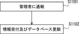
- FIG. 14 is a flowchart showing an example of processing performed by the control device according to the second embodiment when an abnormality occurs in an unmanned aerial vehicle.
- step S1101 of FIG. 14 the administrator is notified that an abnormality has occurred in the unmanned aerial vehicle, and the process proceeds to step S1102.
- the administrator confirms the situation and decides what to do.
- step S1102 the coping method is accepted.
- the control device 100 receives a process for updating the route information, the operation information of the unmanned air vehicle, and the baggage collection place information from the administrator, and updates the route database, the operation database, and the baggage collection place database.
- processing is performed when an abnormality occurs in the unmanned air vehicle.
- relay transportation by an unmanned air vehicle is executed.
- the unmanned aerial vehicle when the route and schedule of the unmanned aerial vehicle are occupied by other unmanned aerial vehicles, the unmanned aerial vehicle is allowed to wait for a predetermined period before flying. By instructing, it is possible to avoid collision between unmanned air vehicles.
- the unmanned aerial vehicle concerned By transmitting the route and schedule for moving to the departure point of the assigned section from the control device to the unmanned aerial vehicle, it is possible to prepare the unmanned aerial vehicle necessary for relay transportation without any shortage.
- the control device when the failure information of the unmanned aerial vehicle is received, the control device assigns the unmanned aerial vehicle that substitutes the section of the unmanned aerial vehicle in which the failure has occurred to cause the failure.
- the control device assigns the unmanned aerial vehicle that substitutes the route and schedule of the unmanned aerial vehicle, even if the unmanned aerial vehicle in charge of transportation fails, it is possible to promptly prepare the unmanned aerial vehicle necessary for relay transportation. it can.
- the alternative destination is determined by determining the destination. It is possible to carry out transportation corresponding to the obstacle.
- the present invention is not limited to the above-mentioned embodiment, and can be modified as appropriate without departing from the spirit of the present invention.
- one-way traffic in the forward direction and one-way traffic in the reverse direction are performed at two altitudes, a high altitude route and a low altitude route, but there are three altitudes for dividing the route.
- the one-way route in the forward direction may be the route with the highest altitude and the route with the second highest altitude
- the one-way route in the reverse direction may be the route with the lowest altitude.
- Each element illustrated in the drawings as a functional block that performs various processes can be configured by a CPU, a memory, and other circuits in terms of hardware, and can be configured by a program loaded in the memory in terms of software. Will be realized. Therefore, it is understood by those skilled in the art that these functional blocks can be realized in various ways by hardware only, software only, or a combination thereof, and is not limited to any of them.
- Non-transitory computer readable media include various types of tangible storage media.
- Examples of non-transitory computer-readable media are magnetic recording media (eg flexible disks, magnetic tapes, hard disk drives), magneto-optical recording media (eg magneto-optical disks), CD-ROMs (Read Only Memory), CD-Rs, It includes a CD-R/W and a semiconductor memory (for example, mask ROM, PROM (Programmable ROM), EPROM (Erasable PROM), flash ROM, RAM (Random Access Memory)).
- the program may also be supplied to the computer by various types of temporary computer-readable media. Examples of temporary computer-readable media include electrical, optical, and electromagnetic waves.
- the transitory computer-readable medium can supply the program to the computer via a wired communication path such as an electric wire and an optical fiber, or a wireless communication path.
- control device 101 communication unit 102 management unit 121 processing unit 122 storage unit 200 transportation system 201 network 202 terminals 203-1 to 203-n unmanned air vehicles 204-1 to 204-m luggage collection points 301-1 to 301-n cargo Storage port 302-1 to 302-n Parking port 303 Storage port
Landscapes
- Traffic Control Systems (AREA)
Abstract
制御装置(100)は、積荷の出発地及び目的地の情報を得る通信部(101)と、積荷を輸送する無人飛行体の経路及びスケジュールを管理する管理部(102)と、を備え、管理部(102)は、積荷の出発地及び目的地に基づいて輸送経路を設定し、管理部(102)は、輸送経路を区間単位で、無人飛行体に割り当て、無人飛行体のスケジュールを設定し、管理部(102)は、無人飛行体の経路及びスケジュールを、輸送経路を区間単位で割り当て、通信部(101)は、区間単位で割り当てられた経路及び設定されたスケジュールを、当該無人飛行体に送信するようにした。
Description
本発明は制御装置、制御方法及び非一時的なコンピュータ可読媒体に関し、例えば、積荷を輸送する無人飛行体の制御装置、制御方法及び非一時的なコンピュータ可読媒体に関する。
無人機、すなわち人が搭乗することなく、自律若しくは遠隔操縦によって3次元的に空間を飛行する無人飛行体、所謂ドローン(Drone)等を利用した様々な技術が考えらており、そのような無人飛行体を用いた利用方法の1つとして物流が挙げられる。現在、このような無人飛行体は、次世代型配達用機械としてその応用が試験、研究されているものであり、物流分野における商用利用の展開が進められている。
例えば、特許文献1には、輸送対象の荷物を収納するコンテナを装着しながら飛行する無人飛行体を用いた輸送システムにおいて、無人飛行体が中継基地で充電される輸送システムが記載されている。
しかしながら、無人飛行体では燃料やバッテリーの容量に限界があるので、飛行可能な距離を超える距離を輸送できないという問題があった。また、燃料を補給またはバッテリーを充電して飛行距離を伸ばす場合、補給または充電に時間がかかってしまうという問題もあった。
一実施形態の制御装置は、積荷の出発地及び目的地の情報を得る通信部と、積荷を輸送する無人飛行体の経路及びスケジュールを管理する管理部と、を備え、前記管理部は、前記積荷の出発地及び目的地に基づいて輸送経路を設定し、前記管理部は、前記輸送経路を区間単位で、前記無人飛行体に割り当て、前記無人飛行体のスケジュールを設定し、前記管理部は、前記無人飛行体の経路及びスケジュールを、前記輸送経路を区間単位で割り当て、前記通信部は、区間単位で割り当てられた経路及び設定されたスケジュールを、当該無人飛行体に送信するようにした。
一実施形態の制御方法は、積荷の出発地及び目的地の情報を得て、前記積荷の出発地及び目的地に基づいて輸送経路を設定し、前記輸送経路を区間単位で、前記無人飛行体に割り当て、前記無人飛行体のスケジュールを設定し、区間単位で割り当てられた経路及びスケジュールを、当該無人飛行体に送信するようにした。
一実施形態の非一時的なコンピュータ可読媒体は、制御装置において、積荷の出発地及び目的地の情報を得るステップと、制御装置において、前記積荷の出発地及び目的地に基づいて輸送経路を設定するステップと、制御装置において、前記輸送経路を区間単位で、前記無人飛行体に割り当て、前記無人飛行体のスケジュールを設定するステップと、制御装置において、区間単位で割り当てられた経路及びスケジュールを、当該無人飛行体に送信するステップと、をコンピュータに実行させるようにした。
本発明の制御装置、制御方法及び非一時的なコンピュータ可読媒体によれば、複数の無人飛行体で積荷を中継輸送することにより、無人飛行体の飛行可能な距離を超える距離を輸送できる。
実施の形態1
以下、図面を参照して本発明の実施の形態について説明する。
図1は、実施の形態1にかかる制御装置の概略構成を示すブロック図である。図1において、制御装置100は、通信部101と、管理部102とを備える。
以下、図面を参照して本発明の実施の形態について説明する。
図1は、実施の形態1にかかる制御装置の概略構成を示すブロック図である。図1において、制御装置100は、通信部101と、管理部102とを備える。
制御装置100は、積荷を無人飛行体で輸送するシステムに用いられる制御装置である。
通信部101は、積荷の出発地及び目的地の情報を得る。また、通信部101は、管理部102によって区間単位で割り当てられた経路及び設定されたスケジュールを、無人飛行体に送信する。例えば、通信部101は、ネットワークを介して、積荷の出発地及び目的地の情報を得る。具体的には、通信部101は、積荷の輸送の依頼を受け付けた端末からネットワークを経由して積荷の出発地及び目的地の情報を得る。また例えば、通信部101は、ネットワークを介して、割り当てられた経路及び設定されたスケジュールを、無人飛行体に送信する。具体的には、通信部101は、割り当てられた経路及び設定されたスケジュールを、ネットワークに接続された無線基地局から無人飛行体に送信する。
管理部102は、積荷を輸送する無人飛行体の経路及びスケジュールを管理する。また、管理部102は、積荷の出発地及び目的地に基づいて輸送経路を設定する。そして、管理部102は、輸送経路を区間単位で、無人飛行体に割り当て、無人飛行体のスケジュールを設定する。管理部102は、無人飛行体の経路及びスケジュールを、輸送経路を区間単位で割り当てる。そして、管理部102は、割り当てを通信部101に伝達する。例えば、管理部102は、CPU(Central Processing Unit)とメモリを備える論理演算装置であってもよい。
このように実施の形態1に制御装置によれば、複数の無人飛行体で積荷を中継輸送することにより、無人飛行体の飛行可能な距離を超える距離を輸送できる。
実施の形態2
実施の形態2では、実施の形態で説明した制御装置の詳細と、制御装置及び無人飛行体を含む輸送システムについて説明する。図2は、実施の形態2にかかる輸送システムの概略構成を示す図である。図2において、図1と同一の構成については、同じ番号を付し、説明を省略する。
実施の形態2では、実施の形態で説明した制御装置の詳細と、制御装置及び無人飛行体を含む輸送システムについて説明する。図2は、実施の形態2にかかる輸送システムの概略構成を示す図である。図2において、図1と同一の構成については、同じ番号を付し、説明を省略する。
図2において、輸送システム200は、制御装置100と、ネットワーク201と、端末202と、無人飛行体203-1~203-nと、荷物集積所204-1~204-mを備える。ここでn及びmは正の整数である。nとmは同じ値であってもよい。また、nとmは異なる値であってもよい。
制御装置100は、実施の形態1で説明した制御装置である。制御装置100は、ネットワーク201を介して、端末202に入力された積荷の出発地及び目的地の情報を得る。また、制御装置100は、ネットワーク201を介して、割り当てられた経路及び設定されたスケジュールを無人飛行体203-1~203-nに送信する。
ネットワーク201は、制御装置100、端末202、無人飛行体203-1~203-n及び荷物集積所204-1~204-m-1間を接続する通信ネットワークである。ネットワーク201は、有線、無線または有線と無線を組み合わせたネットワークである。
端末202は、輸送する積荷の出発地及び目的地の情報を受け付ける端末である。端末202は、入力を受け付けた輸送する積荷の出発地及び目的地の情報を、ネットワーク201を介して制御装置100に送信する。なお、端末202は、荷物集積所204-1~204-m-1内にそれぞれ設けてもよい。
無人飛行体203-1~203-nは、荷物を輸送する飛行体である。例えば、無人飛行体203-1~203-nは、荷物を把持可能であるドローンであってもよい。また、無人飛行体203-1~203-nは、ネットワーク201と有線または無線で接続する通信回路を有する。そして、無人飛行体203-1~203-nは、制御装置100から経路及びスケジュールの情報を受信する。無人飛行体203-1~203-nは、受信した経路及びスケジュールの情報に従い、飛行する。無人飛行体203-1~203-nは、受信した経路で飛行するために、測位装置を有することが望ましい。また、無人飛行体203-1~203-nは、受信した経路で飛行するために、ビーコン(無線標識)を受信する無線受信回路を有するようにしてもよい。
荷物集積所204-1~204-mは、輸送する荷物を無人飛行体203-1~203-nと受け渡しする拠点である。荷物集積所204-1~204-mは、中継輸送する中継点でもある。
以上の構成により、実施の形態2の輸送システム200は、中継輸送を行う。例えば、荷物集積所204-1を出発地とし、荷物集積所204-mを目的地とした荷物の輸送を行う場合、無人飛行体203-1が荷物集積所204-1から荷物集積所204-2に荷物を輸送する。そして、無人飛行体203-2(図示しない)が荷物集積所204-2から荷物集積所204-3(図示しない)に荷物を輸送する。そして、無人飛行体203-nが荷物集積所204-m-1(図示しない)から荷物集積所204-mに荷物を輸送する。
このように、複数の無人飛行体203-1~203-nが荷物を区間単位で中継輸送することにより、出発地から目的地まで荷物を輸送することができる。
次に実施の形態2の制御装置の構成について説明する。図3は、実施の形態2にかかる制御装置の概略構成を示すブロック図である。図3において、制御装置100は、通信部101と、管理部102とを備える。図3において、図1と同一の構成については、同じ番号を付し、説明を省略する。
管理部102は、処理部121及び記憶部122を備える。
処理部121は、以下に説明する各フローの処理を実行する。処理部121は、CPU(Central Processing Unit)とメモリを有する構成としてもよい。また、処理部121は、FPGA(Field-Programmable Gate Array)、ASIC(Application Specific Integrated Circuit)を有する構成としてもよい。
処理部121は、以下に説明する各フローの処理を実行する。処理部121は、CPU(Central Processing Unit)とメモリを有する構成としてもよい。また、処理部121は、FPGA(Field-Programmable Gate Array)、ASIC(Application Specific Integrated Circuit)を有する構成としてもよい。
記憶部122は、以下に説明する各データベースの情報を記憶する。また、記憶部122は、処理部121の要求に応じて記憶している情報を出力する。また、記憶部122は処理部121の書き込みに従い情報を記憶または更新する。記憶部122は、半導体メモリ、磁気メモリ、磁気記憶装置、光磁気記憶装置の少なくとも1つまたは組み合わせであってもよい。
記憶部122は、送り状データベースについて、届け先(目的地)、依頼主、荷姿(サイズ、質量)、品名及び配達日時の項目を関連づけて記憶する。また、記憶部122は、荷物集積所データベースについて、荷物集積所識別番号、空き荷置きポート番号、空き駐機ポート番号、空きボックス番号及び収納荷物の項目を関連づけて記憶する。また、記憶部122は、経路データベースについて、経路番号、荷物集積所番号、荷置きポート番号、駐機ポート番号、無人飛行体の識別番号、到着予告時刻、離陸予定時刻および無人飛行体の待機情報の項目を関連づけて記憶する。また、記憶部122は、運行データベースについて、経路番号、ドローン識別番号、経路進入予定時刻及び経路離脱予定時刻の項目を関連づけて記憶する。
次に、輸送経路の一例について説明する。図4及び図5は、実施の形態2に係る輸送システムにおける、経路の一例を示す図である。図4は、高高度ルートの経路の一例を示す図である。また、図5は、低高度ルートの経路の一例を示す図である。ここで、高高度は、高度(例えば対地高度)が所定より高いルート、低高度は、高度が所定の低いルートを意味する。
図4と図5では同じ緯度または同じ経度のルートで方向が反対になっている。図4のルートを順方向とし、図5のルートを逆方向と定義すると、緯度と経度が同じルートにおいて、順方向と逆方向で異なる高度となっている。したがって、無人飛行体が順方向と逆方向で同時に飛行していても、衝突することがない。
制御装置100の管理部102は、図4及び図5に示すように、緯度と経度が同じルートにおいて、順方向と逆方向で異なる高度となるように無人飛行体の経路を設定する。
このように実施の形態2の制御装置によれば、管理部が、積荷の輸送を担当する無人飛行体の経路を高度別で割り当てることにより、無人飛行体が衝突することがない。
また、実施の形態2の制御装置によれば、管理部が、区間単位の輸送に、緯度と経度が同じルートにおいて順方向と逆方向とで異なる高度の経路を割り当てることにより、無人飛行体が順方向と逆方向で同時に飛行していても、衝突することがない。
次に、荷物集積所204-1~204-mの一例について説明する。図6は、実施の形態2の輸送システムの荷物集積所の一例を示す上面図である。
荷物集積所204-1~204-mは、上面に無人飛行体が着陸及び待機可能な平面を備える。そして図6に示すように、上面に荷置きポート301-1~301-n、駐機ポート302-1~302-n、収納ポート303を備える。
荷置きポート301-1~301-nは、無人飛行体が荷物を降ろすポートである。また、荷置きポート301-1~301-nは、無人飛行体が荷物を載せるポートである。
駐機ポート302-1~302-nは、荷物を下ろした無人飛行体が駐機するポートである。駐機ポート302-1~302-nは、無人飛行体に燃料を補給または電池を充電するようにすることが望ましい。
収納ポート303は、目的地である場合に、荷物を収納するポートである。例えば荷物は収納ポート303より大型宅配荷物集積BOX内に収納されるようにしてもよい(具体的には自動倉庫や自動車の立体駐車場のように搬送機構を用いて収納ポート303から大型宅配荷物集積BOXに荷物を運ぶようにしてもよい)
上述の荷物集積所204-1~204-mにおいて、無人飛行体203-1~203-nが荷物を中継することになる。具体的には以下の手順で中継が行われる。
無人飛行体203-1が、予約された荷置きポート301-1に荷物を降ろす。
次に無人飛行体203-1は駐機ポート302-1に移動して着陸する。
次に無人飛行体203-1は駐機ポート302-1に移動して着陸する。
待機していた後続の無人飛行体203-2が荷置きポート301-1に移動し、荷物をピックアップし、次の荷物集積所204-2に向かって発進する。
同様に荷物集積所204-2から荷物集積所204-mまで無人飛行体203-3~203-nが中継輸送する。
そして、当該ポートが目的地(例えば荷物集積所204-m)の場合、無人飛行体203-nは収納ポートに荷物を降ろす。
上述の中継手順で出発地から目的地まで荷物が輸送される。次に、制御装置の具体的な動作手順について説明する。図7は、実施の形態2の制御装置の正常系フローの一例を示すフローチャートである。
図7のステップS401において、荷物集積所204-1で依頼人より荷物を受け取り、端末202が荷物の輸送先の情報を受け付ける。そしてステップS402に進む。
ステップS402において、制御装置100によって荷物を輸送する経路が設定され、ステップS403に進む。
ステップS402において、制御装置100によって荷物を輸送する経路が設定され、ステップS403に進む。
ステップS403において、制御装置100によって荷物を輸送する経路を区間別に無人飛行体がアサインされ、ステップS404に進む。
ステップS404において、制御装置100によって出発地の無人飛行体が制御され、ステップS405に進む。
ステップS404において、制御装置100によって出発地の無人飛行体が制御され、ステップS405に進む。
ステップS405において、制御装置100によって中継地の無人飛行体が制御され、ステップS406に進む。
ステップS406において、制御装置100によって目的地の無人飛行体が制御され、荷物が目的地に到着する。
ステップS406において、制御装置100によって目的地の無人飛行体が制御され、荷物が目的地に到着する。
次に、上述の各ステップの詳細な動作について説明する。図8は、実施の形態2の制御装置の荷受け処理の一例を示すフローチャートである。
図8のステップS501において、端末202が荷物の輸送を受け付ける。そしてステップS502に進む。
ステップS502において、端末202によって荷物の荷札の読み取りが行われ、ステップS503に進む。
ステップS502において、端末202によって荷物の荷札の読み取りが行われ、ステップS503に進む。
ステップS503において、端末202または制御装置100によって荷物が搬送条件を満たしているか否か判断する。搬送条件は、例えば、荷物の重量、サイズが輸送可能な範囲内であること、目的地が輸送サービスの対象範囲内であることであってもよい。荷物が搬送条件を満たしていない場合ステップS504に進み、荷物が搬送条件を満たしている場合、ステップS505に進む。
ステップS504において、荷物の返却が行われ、処理を終了する。
ステップS505において、制御装置100内のデータベースに送り状の情報が登録され、ステップS506に進む。例えば、制御装置100は、送り状の情報として、例えば届け先(目的地)、依頼主、荷姿(サイズ、質量)、品名、及び配達日時の項目を、送り状データベースにまとめて管理する。
ステップS505において、制御装置100内のデータベースに送り状の情報が登録され、ステップS506に進む。例えば、制御装置100は、送り状の情報として、例えば届け先(目的地)、依頼主、荷姿(サイズ、質量)、品名、及び配達日時の項目を、送り状データベースにまとめて管理する。
ステップS506において、荷物が荷物集積所204-1納められ、荷物が無人飛行体に搭載される準備が整う。
次に経路設定処理について説明する。図9は、実施の形態2の制御装置の経路設定処理の一例を示すフローチャートである。
図9のステップS601において、送り状データベースを参照することにより、出発地、目的地及び配達時刻が設定され、ステップS602に進む。具体的には、ステップS602において、出発の荷物集積所204-1の位置が出発地に設定され、目標の荷物集積所204-mの位置が目的地に設定される。
ステップS602において、経路上の中継する荷物集積所すべてに経路を予約する処理が行われる。経路上にある荷物集積所204のmを1からm-1まで経路をステップS602の処理をループさせる。例えば、経路を予約する処理において、経路番号、荷物集積所番号、荷置きポート番号、駐機ポート番号、到着予告時刻、離陸予定時刻の項目が、経路データベースにまとめて管理される。そして、制御装置100は、この経路データベースを参照することにより、区間毎に経路が予約可能であるか否か判断する。また、新たに予約する経路が区間毎に、経路データベースに書き込まれる。また、制御装置100は、新たに予約する荷物集積所が、荷物集積所データベースに書き込まれる。荷物集積所データベースは、荷物集積所識別番号、空き荷置きポート番号、空き駐機ポート番号、空きボックス番号、収納荷物の項目を有する。
以上の処理により、経路の全区間の設定が行われる。次に、無人飛行体をアサインする処理について説明する。図10は、実施の形態2の制御装置が無人飛行体をアサインする処理の一例を示すフローチャートである。
図10のステップS701において、制御装置100によって、待機している無人飛行体の情報を取得する処理が行われる。そしてステップS702に進む。制御装置100は、この経路データベースを参照することにより、待機している無人飛行体の情報を取得する。経路データベースは上述の項目に加えて、無人飛行体の待機情報の項目を含む。また、制御装置100は、経路データベースの経路番号、荷物集積所番号、到着予告時刻、離陸予定時刻無人飛行体の待機情報の項目を参照することにより、待機している無人飛行体の情報を取得する。
ステップS702において、制御装置100によって、空いている無人飛行体(すなわち、荷物輸送に予約されていない無人飛行体)が、予約された荷物集積所に駐機しているか否か判断される。空いている無人飛行体が予約された荷物集積所に駐機している場合、ステップS703に進み、空いている無人飛行体が予約された荷物集積所に駐機していない場合、ステップS704に進む。
ステップS703において、制御装置100によって、空いている無人飛行体を予約する処理が行われる。制御装置100は、この経路データベースに予約する無人飛行体の情報を書き込む。制御装置100は、予約する無人飛行体の情報を、この経路データベースに書き込む。経路データベースは上述の項目に加えて、無人飛行体の識別番号の項目を含む。また、制御装置100は、経路データベースの経路番号、荷物集積所番号、荷置きポート番号、駐機ポート番号、無人飛行体の識別番号、到着予告時刻、の項目を書き込むことにより、無人飛行体を予約する。
ステップS704において、制御装置100によって、他の荷物集積所から予約された荷物集積所に、空いている無人飛行体を移動させる処理が行われる。制御装置100は、この経路データベースを参照することにより、他の荷物集積所において待機している無人飛行体の情報を取得する。経路データベースは上述の項目に加えて、無人飛行体の待機情報の項目を含む。また、制御装置100は、経路データベースの経路番号、荷物集積所番号、到着予告時刻、離陸予定時刻無人飛行体の待機情報の項目を参照することにより、他の荷物集積所において待機している無人飛行体の情報を取得する。そして、制御装置100は、他の荷物集積所から予約された荷物集積所に移動させる経路を、他の荷物集積所において待機している無人飛行体に送信する。また、制御装置100は、経路データベースの経路番号、荷物集積所番号、荷置きポート番号、駐機ポート番号、無人飛行体の識別番号、到着予告時刻、の項目を書き込むことにより、無人飛行体を予約する。
ステップS701からステップS704の処理を、予約した経路上の荷物集積所(目的地を除く)すべてに実行する。
以上の処理により、無人飛行体がアサインされる。次に、出発地の無人飛行体の処理について説明する。図11は、実施の形態2の制御装置による出発地の無人飛行体の処理の一例を示すフローチャートである。
図11のステップS801において、制御装置100によって、予約した無人飛行体が故障していないか否か判断される。予約した無人飛行体が故障している場合、ステップS802に進む。予約した無人飛行体が故障していない場合、ステップS803に進む。制御装置100は、経路データベースを参照することにより、時刻毎に予約した無人飛行体を抽出し、ステップS801の処理を行う。例えば、制御装置100は、経路番号、荷物集積所番号、荷置きポート番号、駐機ポート番号、無人飛行体の識別番号、到着予告時刻、離陸予定時刻を参照し、ステップS801の処理を行う。
ステップS802において、制御装置100によって、図10のステップS702と同様の無人飛行体の予約処理が行われる。なお、予約できる無人飛行体が出発地に存在しない場合、図10のステップS703と同様の転送予約処理が行われる。そして、ステップS803に進む。
ステップS803において、制御装置100は、予約した無人飛行体に担当区間の経路及びスケジュールを送信し、ステップS804に進む。
ステップS804において、制御装置100は、無人飛行体監視情報に基づいて、無人飛行体に担当区間の経路が他の無人飛行体によって塞がれているか否か判断する。無人飛行体に担当区間の経路が他の無人飛行体によって塞がれている場合、ステップS805に進む。無人飛行体に担当区間の経路が他の無人飛行体によって塞がれていない場合、ステップS806に進む。
ステップS805において、制御装置100は、無人飛行体に所定の期間待機する指示を送信し、所定の期間経過後、ステップS806に進む。
ステップS806において、制御装置は、無人飛行体に発進を指示するとともに、運行データベースを更新する。この運行データベースは、経路番号、ドローン識別番号、経路進入予定時刻及び経路離脱予定時刻を項目として管理する。
以上の処理により、出発地の無人飛行体の処理が行われる。次に、中継地の無人飛行体の処理について説明する。図12は、実施の形態2の制御装置による中継地の無人飛行体の処理の一例を示すフローチャートである。図12において、図11と同じ処理については、同じ番号を付し、説明を省略する。
図12のステップS901において、荷物の設置、無人飛行体の駐機が正常に行われたかを確認される。正常に行われた場合、ステップS801に進む。正常に行われなかった場合、ステップS902に進む。
ステップS902において、制御装置100から管理者に荷物の設置、無人飛行体の駐機が正常に行われなかったことが通報される。
以上の処理により、中継地の無人飛行体の処理が行われる。次に、目的地の無人飛行体の処理について説明する。図13は、実施の形態2の制御装置による目的地の無人飛行体の処理の一例を示すフローチャートである。図13において、図12と同じ処理については、同じ番号を付し、説明を省略する。
図13のステップS901において、荷物の設置、無人飛行体の駐機が正常に行われた場合、ステップS1001に進む。正常に行われなかった場合、ステップS902に進む。
ステップS1001において、制御装置100は、輸送が完了した件について、経路データベース及び運行データベースから当該完了した輸送の情報を削除する。そしてステップS1002に進む。
ステップS1002において、制御装置100は、荷物集積所データベースを参照し、目的地の荷物集積所に異常がないか確認する。目的地の荷物集積所に異常がある場合、ステップS1003に進む。目的地の荷物集積所に異常がない場合、ステップS1004に進む。
ステップS1003において、異常がある目的地から代替の目的地の荷物集積所に荷物を輸送する処理を行う。具体的には、当該処理として、図7のステップS402からステップS406までの処理が行われる。そしてステップS1004に進む。
ステップS1004において、制御装置100が、目的地の荷物集積所にて荷物を収納する指示を出す。そして、制御装置100は、荷物集積所データベースを更新し、ステップS1005に進む。
ステップS1005において、制御装置100は、荷物が正常に収納されたか否か確認する。荷物が正常に収納されていない場合、ステップS1006に進む。荷物が正常に収納されている場合、処理を終了する。
ステップS1006において、制御装置100は、荷物が正常に収納されていないことを管理者に通報する。
以上の処理により、目的地の無人飛行体の処理が行われる。
次に、無人飛行体に異常が発生した時の処理について説明する。図14は、実施の形態2の制御装置による無人飛行体に異常が発生時の処理の一例を示すフローチャートである。
次に、無人飛行体に異常が発生した時の処理について説明する。図14は、実施の形態2の制御装置による無人飛行体に異常が発生時の処理の一例を示すフローチャートである。
図14のステップS1101において、無人飛行体に異常が発生したことを管理者に通報し、ステップS1102に進む。管理者は、状況を確認し、対処方法を決定する。
ステップS1102において、対処方法を受け付ける。具体的には、制御装置100は、管理者からの経路情報、無人飛行体の運行情報、荷物集積所情報を更新する処理を受け付け、経路データベース、運行データベース、荷物集積所データベースを更新する。
以上の処理により、無人飛行体に異常が発生時の処理が行われる。これらの処理により、無人飛行体による中継輸送が実行される。
以上、このように実施の形態2の制御装置によれば、無人飛行体の経路及びスケジュールが他の無人飛行体に占有されている場合、当該無人飛行体を所定の期間待機させた後に飛行を指示することにより、無人飛行体同士が衝突することを回避できる。
また、このように実施の形態2の制御装置によれば、輸送経路を区間単位で割り当てた無人飛行体が割り当てた区間の出発地に、出発時刻前に存在していない場合、当該無人飛行体を割り当てた区間の出発地に移動させる経路及びスケジュールを制御装置から当該無人飛行体に送信することにより、中継輸送に必要な無人飛行体を不足なく用意することができる。
このように実施の形態2の制御装置によれば、無人飛行体の障害情報を受信した場合、制御装置が、障害が発生した無人飛行体の区間を代替する無人飛行体に割り当て、障害が発生した無人飛行体の経路及びスケジュールを代替する無人飛行体に送信することにより、輸送を担当する無人飛行体に障害が発生した場合でも、速やかに中継輸送に必要な無人飛行体を用意することができる。
このように実施の形態2の制御装置によれば、輸送経路の目的地の障害情報を受信し、輸送経路の目的地の障害情報を受信した場合、代替目的地を決定することにより、目的地の障害に対応した輸送を実行できる。
なお、本発明は上記実施の形態に限られたものではなく、趣旨を逸脱しない範囲で適宜変更することが可能である。例えば、上記実施の形態では、高高度ルートと、低高度ルートの2つの高度で、順方向の一方通行と逆方向の一方通行とする例を説明しているが、ルートを分ける高度は3つ以上でもよい。例えば、順方向の一方通行とするルートを、最も高い高度のルートと、2番目に高い高度のルートとし、逆方向の一方通行とするルートを、最も低い高度のルートとしてもよい。
様々な処理を行う機能ブロックとして図面に記載される各要素は、ハードウェア的には、CPU、メモリ、その他の回路で構成することができ、ソフトウェア的には、メモリにロードされたプログラムなどによって実現される。したがって、これらの機能ブロックがハードウェアのみ、ソフトウェアのみ、またはそれらの組合せによっていろいろな形で実現できることは当業者には理解されるところであり、いずれかに限定されるものではない。
また、上述したプログラムは、様々なタイプの非一時的なコンピュータ可読媒体を用いて格納され、コンピュータに供給することができる。非一時的なコンピュータ可読媒体は、様々なタイプの実体のある記録媒体を含む。非一時的なコンピュータ可読媒体の例は、磁気記録媒体(例えばフレキシブルディスク、磁気テープ、ハードディスクドライブ)、光磁気記録媒体(例えば光磁気ディスク)、CD-ROM(Read Only Memory)、CD-R、CD-R/W、半導体メモリ(例えば、マスクROM、PROM(Programmable ROM)、EPROM(Erasable PROM)、フラッシュROM、RAM(Random Access Memory))を含む。また、プログラムは、様々なタイプの一時的なコンピュータ可読媒体によってコンピュータに供給されてもよい。一時的なコンピュータ可読媒体の例は、電気信号、光信号、及び電磁波を含む。一時的なコンピュータ可読媒体は、電線及び光ファイバ等の有線通信路、又は無線通信路を介して、プログラムをコンピュータに供給できる。
この出願は、2019年3月6日に出願された日本出願特願2019-40746を基礎とする優先権を主張し、その開示の全てをここに取り込む。
100 制御装置
101 通信部
102 管理部
121 処理部
122 記憶部
200 輸送システム
201 ネットワーク
202 端末
203-1~203-n 無人飛行体
204-1~204-m 荷物集積所
301-1~301-n 荷置きポート
302-1~302-n 駐機ポート
303 収納ポート
101 通信部
102 管理部
121 処理部
122 記憶部
200 輸送システム
201 ネットワーク
202 端末
203-1~203-n 無人飛行体
204-1~204-m 荷物集積所
301-1~301-n 荷置きポート
302-1~302-n 駐機ポート
303 収納ポート
Claims (9)
- 積荷の出発地及び目的地の情報を得る通信部と、
積荷を輸送する無人飛行体の経路及びスケジュールを管理する管理部と、
を備え、
前記管理部は、前記積荷の出発地及び目的地に基づいて輸送経路を設定し、
前記管理部は、前記輸送経路を区間単位で、前記無人飛行体に割り当て、前記無人飛行体のスケジュールを設定し、
前記管理部は、前記無人飛行体の経路及びスケジュールを、前記輸送経路を区間単位で割り当て、
前記通信部は、区間単位で割り当てられた経路及び設定されたスケジュールを、当該無人飛行体に送信する、制御装置。 - 前記管理部は、前記積荷の輸送を担当する無人飛行体の経路を高度別で割り当てる請求項1に記載の制御装置。
- 前記管理部は、区間単位の輸送に、緯度と経度が同じルートにおいて順方向と逆方向とで異なる高度の経路を割り当てる請求項2に記載の制御装置。
- 前記管理部は、前記無人飛行体の経路及びスケジュールを記憶する記憶部を有し、
前記管理部は、無人飛行体の経路及びスケジュールが他の無人飛行体に占有されている場合、当該無人飛行体を所定の期間待機させた後に飛行を指示する請求項1から3のいずれかに記載の制御装置。 - 前記輸送経路を区間単位で割り当てた無人飛行体が割り当てた区間の出発地に、出発時刻前に存在していない場合、前記通信部は、当該無人飛行体を割り当てた区間の出発地に移動させる経路及びスケジュールを当該無人飛行体に送信する請求項1から4のいずれかに記載の制御装置。
- 前記通信部は、前記無人飛行体の障害情報を受信し、
前記無人飛行体の障害情報を受信した場合、前記管理部は、障害が発生した無人飛行体の区間を代替する無人飛行体に割り当て、
前記通信部は、障害が発生した無人飛行体の経路及びスケジュールを代替する無人飛行体に送信する請求項1から5のいずれかに記載の制御装置。 - 前記通信部は、輸送経路の目的地の障害情報を受信し、
前記輸送経路の目的地の障害情報を受信した場合、前記管理部は、代替目的地を決定し、
前記管理部は、前記代替目的地に飛行する代替輸送経路を決定し、
前記管理部は、前記代替輸送経路を区間単位で、前記無人飛行体に割り当て、前記無人飛行体のスケジュールを設定し、
前記管理部は、前記無人飛行体の経路及びスケジュールを、前記代替輸送経路を区間単位で割り当て、
前記通信部は、区間単位で割り当てられた経路及び設定されたスケジュールを、当該無人飛行体に送信する請求項1から6のいずれかに記載の制御装置。 - 積荷の出発地及び目的地の情報を得て、
前記積荷の出発地及び目的地に基づいて輸送経路を設定し、
前記輸送経路を区間単位で、無人飛行体に割り当て、前記無人飛行体のスケジュールを設定し、
区間単位で割り当てられた経路及びスケジュールを、当該無人飛行体に送信する、制御方法。 - 制御装置において、積荷の出発地及び目的地の情報を得るステップと、
制御装置において、前記積荷の出発地及び目的地に基づいて輸送経路を設定するステップと、
制御装置において、前記輸送経路を区間単位で、無人飛行体に割り当て、前記無人飛行体のスケジュールを設定するステップと、
制御装置において、区間単位で割り当てられた経路及びスケジュールを、当該無人飛行体に送信するステップと、をコンピュータに実行させる制御プログラムをコンピュータに実行させる非一時的なコンピュータ可読媒体。
Priority Applications (1)
| Application Number | Priority Date | Filing Date | Title |
|---|---|---|---|
| JP2021503425A JPWO2020179195A1 (ja) | 2019-03-06 | 2019-12-20 | 制御装置、制御方法及び制御プログラム |
Applications Claiming Priority (2)
| Application Number | Priority Date | Filing Date | Title |
|---|---|---|---|
| JP2019040746 | 2019-03-06 | ||
| JP2019-040746 | 2019-03-06 |
Publications (1)
| Publication Number | Publication Date |
|---|---|
| WO2020179195A1 true WO2020179195A1 (ja) | 2020-09-10 |
Family
ID=72338560
Family Applications (1)
| Application Number | Title | Priority Date | Filing Date |
|---|---|---|---|
| PCT/JP2019/050078 Ceased WO2020179195A1 (ja) | 2019-03-06 | 2019-12-20 | 制御装置、制御方法及び非一時的なコンピュータ可読媒体 |
Country Status (2)
| Country | Link |
|---|---|
| JP (1) | JPWO2020179195A1 (ja) |
| WO (1) | WO2020179195A1 (ja) |
Cited By (4)
| Publication number | Priority date | Publication date | Assignee | Title |
|---|---|---|---|---|
| JP7072115B1 (ja) | 2020-12-28 | 2022-05-19 | Kddi株式会社 | 情報処理装置、情報処理方法及びプログラム |
| JP2022077280A (ja) * | 2020-11-11 | 2022-05-23 | トヨタ自動車株式会社 | 制御装置、無人航空機、及び方法 |
| JP2022104645A (ja) * | 2021-11-12 | 2022-07-08 | Kddi株式会社 | 情報処理装置、情報処理方法及びプログラム |
| JP2022104091A (ja) * | 2020-12-28 | 2022-07-08 | Kddi株式会社 | 情報処理装置、情報処理方法及び情報処理システム |
Citations (4)
| Publication number | Priority date | Publication date | Assignee | Title |
|---|---|---|---|---|
| JP2000172992A (ja) * | 1998-12-09 | 2000-06-23 | Fujitsu Ltd | 車載型車両誘導装置及び通信サーバシステム並びに代替車両誘導システム |
| JP2002205824A (ja) * | 2001-01-09 | 2002-07-23 | Furiiran:Kk | 貨物の集配システム |
| JP2017105242A (ja) * | 2015-12-07 | 2017-06-15 | 高木 賀子 | 無人飛行体を用いた輸送システム |
| JP2018513456A (ja) * | 2015-03-02 | 2018-05-24 | アマゾン テクノロジーズ インコーポレイテッド | 輸送用の移動する輸送車両における無人航空機の着陸 |
Family Cites Families (3)
| Publication number | Priority date | Publication date | Assignee | Title |
|---|---|---|---|---|
| CN109416889A (zh) * | 2016-06-13 | 2019-03-01 | 深圳市大疆创新科技有限公司 | 无人飞行器、配送系统、无人飞行器的控制方法以及控制无人飞行器的程序 |
| JP6822790B2 (ja) * | 2016-06-28 | 2021-01-27 | 日本ユニシス株式会社 | ドローンを用いた自動防霜システム |
| JP2019031204A (ja) * | 2017-08-08 | 2019-02-28 | シャープ株式会社 | 無人航空機、管理サーバ、制御装置、および制御プログラム |
-
2019
- 2019-12-20 WO PCT/JP2019/050078 patent/WO2020179195A1/ja not_active Ceased
- 2019-12-20 JP JP2021503425A patent/JPWO2020179195A1/ja active Pending
Patent Citations (4)
| Publication number | Priority date | Publication date | Assignee | Title |
|---|---|---|---|---|
| JP2000172992A (ja) * | 1998-12-09 | 2000-06-23 | Fujitsu Ltd | 車載型車両誘導装置及び通信サーバシステム並びに代替車両誘導システム |
| JP2002205824A (ja) * | 2001-01-09 | 2002-07-23 | Furiiran:Kk | 貨物の集配システム |
| JP2018513456A (ja) * | 2015-03-02 | 2018-05-24 | アマゾン テクノロジーズ インコーポレイテッド | 輸送用の移動する輸送車両における無人航空機の着陸 |
| JP2017105242A (ja) * | 2015-12-07 | 2017-06-15 | 高木 賀子 | 無人飛行体を用いた輸送システム |
Cited By (9)
| Publication number | Priority date | Publication date | Assignee | Title |
|---|---|---|---|---|
| JP2022077280A (ja) * | 2020-11-11 | 2022-05-23 | トヨタ自動車株式会社 | 制御装置、無人航空機、及び方法 |
| JP7415881B2 (ja) | 2020-11-11 | 2024-01-17 | トヨタ自動車株式会社 | 制御装置、無人航空機、及び方法 |
| JP7072115B1 (ja) | 2020-12-28 | 2022-05-19 | Kddi株式会社 | 情報処理装置、情報処理方法及びプログラム |
| JP2022104091A (ja) * | 2020-12-28 | 2022-07-08 | Kddi株式会社 | 情報処理装置、情報処理方法及び情報処理システム |
| JP2022104545A (ja) * | 2020-12-28 | 2022-07-08 | Kddi株式会社 | 情報処理装置、情報処理方法及びプログラム |
| JP2022104645A (ja) * | 2021-11-12 | 2022-07-08 | Kddi株式会社 | 情報処理装置、情報処理方法及びプログラム |
| JP7244700B2 (ja) | 2021-11-12 | 2023-03-22 | Kddi株式会社 | 情報処理装置、情報処理方法及びプログラム |
| JP2023060887A (ja) * | 2021-11-12 | 2023-04-28 | Kddi株式会社 | 情報端末、情報処理方法及びプログラム |
| JP7404574B2 (ja) | 2021-11-12 | 2023-12-25 | Kddi株式会社 | 情報処理システム及び情報処理方法 |
Also Published As
| Publication number | Publication date |
|---|---|
| JPWO2020179195A1 (ja) | 2021-12-16 |
Similar Documents
| Publication | Publication Date | Title |
|---|---|---|
| WO2020179195A1 (ja) | 制御装置、制御方法及び非一時的なコンピュータ可読媒体 | |
| US10131451B2 (en) | Pre-flight self test for unmanned aerial vehicles (UAVs) | |
| US11905014B2 (en) | Terminal area operation of UAVs for package delivery system | |
| US11587015B2 (en) | System and method for delivering articles from a start point to a destination point by means of drones | |
| US9792576B1 (en) | Operating a plurality of drones and trucks in package delivery | |
| CN109906186B (zh) | 用于无人驾驶飞机的自动化回收系统 | |
| US20170233053A1 (en) | Gas-filled carrier aircrafts and methods of dispersing unmanned aircraft systems in delivering products | |
| KR20190126756A (ko) | 멀티-릴레이 스테이션 환경에 기반하는 무인 비행체를 이용한 물류 운송 방법 및 시스템 | |
| CN107148371A (zh) | 用于提供物体的运送服务的计算机化系统和方法 | |
| CN114331247A (zh) | 利用无人机的运送服务的系统及方法 | |
| WO2020144391A1 (en) | A method and apparatus for secure delivery of cargo | |
| KR20230086827A (ko) | 인공지능 기반의 물류 배송 드론의 운영 시스템 | |
| CN114792217A (zh) | 用于分散混合空地自主最后一英里货物递送的系统和方法 | |
| CN113119835A (zh) | 运送系统以及运送管理服务器、飞行体、行驶体 | |
| CN114072828A (zh) | 改进的托运物在移动运输单元处的投放 | |
| KR20250036092A (ko) | 멀티-릴레이 스테이션 환경에 기반하는 무인 비행체를 이용한 물류 운송 방법 및 시스템 | |
| US20240217681A1 (en) | Power feed management device, computer readable storage medium, system, flight vehicle, and method | |
| TWI645370B (zh) | 配對無人機與貨運車使無人機完成貨品收送之系統及方法 | |
| EP4682854A1 (en) | Confirming a planned route | |
| US20240379011A1 (en) | Process and machine to move resources | |
| CN116307992A (zh) | 一种用于固定翼大型货运无人机的物流管理系统、方法 | |
| JP2024013380A (ja) | 移動体運行管理装置 | |
| CN113128817A (zh) | 基于飞行器的运输控制方法和运输控制系统 | |
| WO2023119559A1 (ja) | 充電設備決定装置、充電設備決定方法、及び記録媒体 | |
| ES2970860A1 (es) | Sistema y metodo para entregar un paquete mediante un vehiculo aereo no tripulado |
Legal Events
| Date | Code | Title | Description |
|---|---|---|---|
| 121 | Ep: the epo has been informed by wipo that ep was designated in this application |
Ref document number: 19918490 Country of ref document: EP Kind code of ref document: A1 |
|
| ENP | Entry into the national phase |
Ref document number: 2021503425 Country of ref document: JP Kind code of ref document: A |
|
| NENP | Non-entry into the national phase |
Ref country code: DE |
|
| 122 | Ep: pct application non-entry in european phase |
Ref document number: 19918490 Country of ref document: EP Kind code of ref document: A1 |