WO2020179174A1 - 映像処理装置、映像処理方法および映像処理プログラム - Google Patents
映像処理装置、映像処理方法および映像処理プログラム Download PDFInfo
- Publication number
- WO2020179174A1 WO2020179174A1 PCT/JP2019/048641 JP2019048641W WO2020179174A1 WO 2020179174 A1 WO2020179174 A1 WO 2020179174A1 JP 2019048641 W JP2019048641 W JP 2019048641W WO 2020179174 A1 WO2020179174 A1 WO 2020179174A1
- Authority
- WO
- WIPO (PCT)
- Prior art keywords
- frame
- face
- image
- brightness
- unit
- Prior art date
- Legal status (The legal status is an assumption and is not a legal conclusion. Google has not performed a legal analysis and makes no representation as to the accuracy of the status listed.)
- Ceased
Links
Images



Classifications
-
- G—PHYSICS
- G03—PHOTOGRAPHY; CINEMATOGRAPHY; ANALOGOUS TECHNIQUES USING WAVES OTHER THAN OPTICAL WAVES; ELECTROGRAPHY; HOLOGRAPHY
- G03B—APPARATUS OR ARRANGEMENTS FOR TAKING PHOTOGRAPHS OR FOR PROJECTING OR VIEWING THEM; APPARATUS OR ARRANGEMENTS EMPLOYING ANALOGOUS TECHNIQUES USING WAVES OTHER THAN OPTICAL WAVES; ACCESSORIES THEREFOR
- G03B15/00—Special procedures for taking photographs; Apparatus therefor
-
- G—PHYSICS
- G03—PHOTOGRAPHY; CINEMATOGRAPHY; ANALOGOUS TECHNIQUES USING WAVES OTHER THAN OPTICAL WAVES; ELECTROGRAPHY; HOLOGRAPHY
- G03B—APPARATUS OR ARRANGEMENTS FOR TAKING PHOTOGRAPHS OR FOR PROJECTING OR VIEWING THEM; APPARATUS OR ARRANGEMENTS EMPLOYING ANALOGOUS TECHNIQUES USING WAVES OTHER THAN OPTICAL WAVES; ACCESSORIES THEREFOR
- G03B7/00—Control of exposure by setting shutters, diaphragms or filters, separately or conjointly
- G03B7/08—Control effected solely on the basis of the response, to the intensity of the light received by the camera, of a built-in light-sensitive device
- G03B7/091—Digital circuits
- G03B7/093—Digital circuits for control of exposure time
-
- H—ELECTRICITY
- H04—ELECTRIC COMMUNICATION TECHNIQUE
- H04N—PICTORIAL COMMUNICATION, e.g. TELEVISION
- H04N23/00—Cameras or camera modules comprising electronic image sensors; Control thereof
- H04N23/60—Control of cameras or camera modules
-
- H—ELECTRICITY
- H04—ELECTRIC COMMUNICATION TECHNIQUE
- H04N—PICTORIAL COMMUNICATION, e.g. TELEVISION
- H04N23/00—Cameras or camera modules comprising electronic image sensors; Control thereof
- H04N23/70—Circuitry for compensating brightness variation in the scene
Definitions
- the present invention relates to a video processing apparatus, a video processing method, and a video processing program.
- an image obtained by photographing the outside of the vehicle or the inside of the vehicle is stored in a storage device.
- the state of the interior of the vehicle is memorized as an image, and the image is memorized mainly by the driver.
- Patent Document 1 discloses a video processing device including an exposure amount control means, a difference image generation means, and a disturbance light change frequency prediction means.
- the exposure amount control means controls the exposure amount of the image pickup means by at least one of the exposure time of the image pickup means and the diaphragm.
- the difference image generation means generates a difference image between an image of a subject taken by the imaging means with the lighting means turned on and an image of the subject taken by the imaging means with the lighting means turned off.
- the disturbance light change frequency prediction unit predicts a vehicle traveling section (a disturbance light change small section) in which the change frequency of the disturbance light incident on the imaging unit is smaller than a predetermined threshold.
- the exposure amount control means fixes the exposure amount in the disturbance light change small section predicted by the disturbance light change frequency prediction means.
- the conventional video processing device described in Patent Document 1 functions to prevent blackout and whiteout by predicting the frequency of changes in ambient light.
- image information corresponding to the face part in the shadowed part is lost.
- the state of the image subject such as the degree of opening and closing of the eyes is analyzed based on the image. Difficult to do.
- the present invention has been made in view of such circumstances, and an object of the present invention is an image processing device, an image processing method, and an image processing program capable of suppressing the loss of image information corresponding to a facial part. Is to provide.
- the image processing apparatus includes an image acquisition unit that acquires an image of the face of the image subject, and an image detection unit that detects a facial portion from the image acquired by the image acquisition unit.
- a brightness value acquisition unit that acquires a brightness value in the face portion detected by the image detection unit, and a brightness that determines whether or not the brightness value acquired by the brightness value acquisition unit is within a predetermined brightness range.
- the determination unit includes a determination unit and a frame control unit that generates a frame subjected to exposure control with an exposure control value corresponding to a region determined to be outside the luminance range by the luminance determination unit.
- This image processing method comprises an image acquisition step of acquiring an image of the face of an image to be imaged, an image detection step of detecting a facial portion from the image acquired by the image acquisition step, and the image detection step.
- a brightness value acquisition step for acquiring the detected brightness value of the face portion, a brightness determination step for determining whether or not the brightness value acquired by the brightness value acquisition step is within a predetermined brightness range, and the brightness It includes a frame control step for generating a frame whose exposure is controlled by an exposure control value corresponding to a portion determined to be out of the luminance range by the determination step.
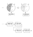
- FIG. 2A is a schematic diagram for explaining exposure control for the entire face
- FIG. 2B is a schematic diagram for explaining the generated frame
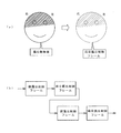
- FIG. 3A is a schematic diagram for explaining an example of exposure control for eyes
- FIG. 3B is a schematic diagram for explaining a frame to be generated.
- FIG. 4A is a schematic diagram for explaining another example of exposure control for the eyes
- FIG. 4B is a schematic diagram for explaining the generated frame.
- FIG. 5A is a schematic diagram for explaining yet another example of exposure control for the eyes
- FIG. 5B is a schematic diagram for explaining the generated frame.
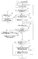
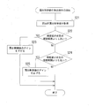
- It is a flowchart which shows the procedure of the frame generation processing in a video processing apparatus. It is a flowchart which shows the procedure of calculation process of the exposure control value in a video processing apparatus.
- FIG. 1 is a block diagram showing a configuration of a driver monitor 100 including a video processing device 30 according to an embodiment.
- the driver monitor 100 is mounted on the vehicle and continuously photographs the interior of the vehicle in time.
- the driver monitor 100 may record the captured image, or may discard the captured image without recording the image.
- the driver monitor 100 is arranged, for example, on the dashboard below the windshield of the vehicle.
- the image processing device 30 of the driver monitor 100 photographs, for example, a driver who is in a vehicle as an image-captured object, and detects the face, face eyes, nose, mouth, and the like of the imaged object.
- the image processing device 30 acquires the luminance value for the entire face and each part of the face, and controls the exposure by comparing with the reference luminance value.
- the image processing device 30 performs exposure control for the entire face, and when each part has a large brightness difference from the brightness reference value, generates a frame for which exposure control is performed corresponding to each part.
- the image processing device 30 controls frames by sequentially generating a face exposure control frame, a right eye exposure control frame, a left eye exposure control frame, and the like whose exposure is controlled for the entire face, and video data composed of time-series frames. To generate.
- the right eye exposure control frame and the left eye exposure control frame make it easier to distinguish the contours of the left and right eyes, and relate to eye parts such as the degree of opening and closing of the eyes and the inclination of the left and right eyes. It is suitable for analysis.
- the description of the analysis function related to the eye portion is omitted, but the image processing apparatus 30 may be provided with an analysis function related to the eye portion such as the degree of opening and closing of the eyes and the inclination of the left and right eyes.
- the eye part may be analyzed in an external device.
- the analysis function related to the eye portion such as the degree of opening and closing of the eyes and the inclination of the left and right eyes is used, for example, to determine the degree of drowsiness in the imaged object and to determine an emotional state (for example, a normal state or a tense state).
- the driver monitor 100 includes an imaging unit 10, a recording unit 20, a video processing device 30, an external input unit 40, an external output unit 41, and the like.
- the image capturing unit 10 is a camera having a detector such as a CCD, and captures an image of, for example, a driver in a vehicle as an imaged object.
- the imaging unit 10 appropriately irradiates infrared light to the object to be imaged so that the object to be imaged such as a driver can be imaged even in the dark at night.
- the image capturing unit 10 acquires video continuously in time and sends it to a video acquisition unit 31 of the video processing device 30 described later.
- the recording unit 20 is, for example, a removable medium such as an SD card or a USB memory, a hard disk, or the like, and is capable of recording the image acquired by the image acquisition unit 31 and deleting the image.
- a removable medium such as an SD card or a USB memory, a hard disk, or the like
- the recording unit 20 may not be provided.
- the external input unit 40 acquires vehicle speed information, position information, and the like from an external device. Further, the external output unit 41 outputs the video information and the like processed by the video processing device 30 to the external device.
- the driver monitor 100 may add the speed information, the position information, and the like acquired by the external input unit 40 to the video and record or output the video.
- the image processing device 30 includes an image acquisition unit 31, a frame control unit 32, an image detection unit 33, a face brightness value acquisition unit 34, a part brightness value acquisition unit 35, a brightness determination unit 36, and an exposure control value calculation unit 37.
- the video processing device 30 is configured by, for example, a CPU (Central Processing Unit) or the like, and executes processing by each of the above-mentioned parts by operating according to a computer program.
- the storage unit 30a is composed of a data storage device such as a RAM (RandomAccessMemory), a flash memory, and a hard disk storage device, and stores a computer program or the like executed by the video processing device 30. Further, the storage unit 30a stores a recognition dictionary for recognizing the face, eyes, and the like of the image subject from the captured image.
- the video acquisition unit 31 acquires the video captured by the imaging unit 10 and outputs it to the frame control unit 32.
- the image acquisition unit 31 may be configured to include the imaging unit 10.
- the frame control unit 32 generates frames in time series based on the video input from the video acquisition unit 31, and outputs the frames to the recording unit 20.
- the frame control unit 32 controls the exposure corresponding to each part of the face and the eyes, nose, mouth, etc. of the face, and the face exposure control frame, the right-eye exposure control frame, and the left-eye exposure that are exposure-controlled for the entire face. Control frames etc. are generated sequentially.
- the frame control unit 32 outputs the video input from the video acquisition unit 31 to the video detection unit 33, and the processing for setting the exposure amount by the video detection unit 33 or the like is executed.
- the frame controller 32 will be described later.
- the image detection unit 33 detects the face of the object to be imaged and each part of the face such as eyes, nose and mouth from the image input from the frame control unit 32 based on the recognition dictionary stored in the storage unit 30a. To do.
- the recognition dictionary stored in the storage unit 30a includes shape data of the face and each part of the face, and the image detection unit 33 extracts the shape pattern appearing in the image and is a recognition dictionary.
- the face, each part of the face, and the like are detected by collating with the shape data included in.
- the image detection unit 33 can detect faces, eyes, and the like from images by using known image recognition processing methods that have been developed in various fields.
- the face brightness value acquisition unit 34 acquires the brightness value of the face in order to control the exposure of the entire face.
- the face brightness value acquisition unit 34 calculates a brightness average value in the face detection frame and acquires it as a face brightness value.
- the face detection frame is a frame including an image of a face portion detected by image recognition processing or the like, and the brightness value of the face is acquired by calculating the average brightness value in the frame.
- the part brightness value acquisition unit 35 acquires the brightness value of each part in order to control the exposure of each part such as the eyes, nose and mouth of the face.
- the part brightness value acquisition unit 35 calculates the brightness average value in the eye detection frame, the nose detection frame, and the mouth detection frame, and acquires it as the brightness value of each part.
- the eye detection frame, nose detection frame, and mouth detection frame are frames including images of each part of the eyes, nose, and mouth detected by image recognition processing or the like, and are included in the frame.
- the brightness value of each part is acquired by calculating the brightness average value.
- the brightness determination unit 36 determines whether or not the brightness value of the face acquired by the face brightness value acquisition unit 34 and the brightness value of each part of the face acquired by the part brightness value acquisition unit 35 are within a predetermined brightness range. To judge. The brightness determination unit 36 calculates the brightness difference between the face brightness value and the face reference brightness value, and determines whether or not the brightness difference is less than or equal to a predetermined threshold value, so that the face brightness value has a predetermined It is determined whether or not it is within the brightness range. Further, the brightness determination unit 36 calculates a brightness difference between the brightness value of each part of the face and the reference brightness value of each part, and determines whether the brightness difference is equal to or less than a predetermined threshold value. It is determined whether the brightness value of each part of the face is within a predetermined brightness range. The brightness determination unit 36 outputs the determination result and the brightness difference for the face and each part of the face to the exposure control value calculation unit 37.
- the exposure control value calculation unit 37 calculates the exposure control value when the brightness value is outside the predetermined brightness range in the determination result input from the brightness determination unit 36. When the brightness value of the face and each part of the face is higher than the corresponding reference brightness value, the exposure control value calculation unit 37 increases the shutter speed and calculates the exposure control value to reduce the gain. Further, the exposure control value calculation unit 37 calculates the exposure control value in order to slow down the shutter speed and increase the gain when the brightness value of the face and each part of the face is lower than the corresponding reference brightness value. ..
- the exposure control value calculation unit 37 outputs the exposure control value calculated for the face and each part of the face to the frame control unit 32, and the frame control unit 32 outputs the exposure control value to the imaging unit 10 to perform the exposure control. Perform value-based control.
- the frame control unit 32 sets the frame configuration based on the exposure control value for the face and each part of the face input from the exposure control value calculation unit 37.
- FIG. 2A is a schematic diagram for explaining the exposure control for the entire face
- FIG. 2B is a schematic diagram for explaining the generated frame.
- the image of the entire face before exposure control is dark, and the luminance value of the face is lower than the reference luminance value and outside the predetermined luminance range.
- the frame control unit 32 controls the exposure in the imaging unit 10 based on the exposure control value calculated by the exposure control value calculation unit 37 so as to control the exposure for the entire face. In this case, the frame control unit 32 controls the image capturing unit 10 with an exposure control value that slows the shutter speed and increases the gain.
- the exposure control by the frame control unit 32 is not necessarily completed by a single control, and may be a control in which the gain is stepwise increased until the brightness value becomes appropriate for the blackout image. ..
- the frame control unit 32 reuses the exposure control value of the frame acquired last time in the frame acquired in time series when acquiring the current frame. , May be operated to reduce the number of trials of exposure control.
- the frame control unit 32 executes not only the exposure control for the entire face but also the exposure control for each part of the face, which will be described later, by performing such stepwise exposure control and exposure control by reusing the exposure control value. You may.
- the stepwise exposure control and the reuse of the exposure control value will be omitted for the sake of brevity.
- the frame control unit 32 generates an image taken after the exposure control as a face exposure control frame in chronological order and outputs the image to the recording unit 20.
- the frame control unit 32 generates an exposure-controlled frame corresponding to each part based on the brightness value of each part of the face in the face exposure control frame.
- FIG. 3A is a schematic diagram for explaining an example of exposure control for eyes
- FIG. 3B is a schematic diagram for explaining a frame to be generated.
- the brightness value of the right eye is lower than the reference brightness value and is outside the predetermined brightness range
- the brightness value of the left eye is within the brightness range.
- the frame control unit 32 controls the exposure in the imaging unit 10 based on the exposure control value calculated by the exposure control value calculation unit 37 so as to control the exposure corresponding to the right eye.
- the exposure control value output from the exposure control value calculation unit 37 to the image pickup unit 10 slows the shutter speed and increases the gain.
- the frame control unit 32 time-sequentially generates an image captured after exposure control as a right-eye exposure control frame. That is, the frame control unit 32 generates a frame for the captured image with a frame configuration that generates a right eye exposure control frame after the face exposure control frame.
- FIG. 4A is a schematic diagram for explaining another example of the exposure control for the eyes
- FIG. 4B is a schematic diagram for explaining the generated frame.
- the brightness value of the right eye is lower than the reference brightness value and outside the predetermined brightness range
- the brightness value of the left eye is higher than the reference brightness value and outside the brightness range.
- the frame control unit 32 controls the exposure for the right eye, and subsequently controls the exposure for the left eye.
- the right eye brightness control frame will have proper right eye brightness
- the left eye exposure control frame will have proper left eye brightness.
- the frame control unit 32 time-sequentially generates images captured after exposure control as a right-eye exposure control frame and a left-eye exposure control frame. That is, the frame control unit 32 has a frame structure that generates a right-eye exposure control frame and a left-eye exposure control frame after the face-exposure control frame, and continues to generate frames for captured images.
- FIG. 5A is a schematic diagram for explaining still another example of the exposure control for the eyes
- FIG. 5B is a schematic diagram for explaining the generated frame.
- the brightness values of the left and right eyes are lower than the reference brightness value and are outside the predetermined brightness range.
- the frame controller 32 needs to control the exposure corresponding to both the left and right eyes.
- the exposure control value may be calculated so that the average value of the brightness values of the left eye and the right eye approaches the reference brightness value, but the method is not limited to this.
- the brightness value of the image captured after the exposure control becomes appropriate for both eyes.
- the frame control unit 32 generates images taken after exposure control as binocular exposure control frames in chronological order. That is, the frame control unit 32 generates a frame for the captured image with a frame configuration that generates a binocular exposure control frame after the face exposure control frame.
- FIG. 6 is a flowchart showing a procedure of frame generation processing in the video processing device 30. It is assumed that the image processing device 30 acquires an image and obtains a detection frame for the face and each part of the face.
- the face brightness value acquisition unit 34 of the image processing device 30 acquires the face brightness value from the input image (S1).
- the brightness determination unit 36 determines whether or not the brightness value of the face is within a predetermined brightness range (S2). If the determination result in step S2 is negative and the brightness value of the face is outside the predetermined brightness range (S2: NO), the exposure control value calculation unit 37 executes the process of calculating the exposure control value for the face (S3). ..
- the frame control unit 32 controls the exposure of the imaging unit 10 based on the exposure control value for the face calculated by the exposure control value calculation unit 37 to generate a face exposure control frame (S4), returns to step S1 and repeats the process. ..
- the currently generated frame is recorded in the recording unit 20 as the face exposure control frame (S5). Further, the current exposure control value is stored in the storage unit 30a as the exposure control value for the face (S6). Next, the part brightness value acquisition unit 35 acquires the brightness value of each part of the face (S7).
- the brightness determination unit 36 determines whether or not there is a portion in which the brightness value of each portion of the face is within the predetermined luminance range (S8), and when there is a portion within the predetermined luminance range (S8: YES), the current frame is recorded in the recording unit 20 as an exposure control frame for each part of the portion within the brightness range (S9). Further, the current exposure control value is stored in the storage unit 30a as an exposure control value for a portion within the brightness range (S10). After the step S10 and when the determination result is no in step S8 (S8: NO), the frame control unit 32 determines whether or not the exposure control frame has been recorded for all the parts (S11).
- step S11 If the result is negative in step S11 (S11: NO), the exposure control frame is not recorded in the frame control unit 32 because there is a portion where the exposure control is still insufficient, and the brightness value is the brightness.
- the calculation process of the exposure control value for the part outside the range is executed.
- the exposure control value calculation process in step S12 is the same as the process in step S3.
- the frame control unit 32 controls the exposure of the imaging unit 10 based on the exposure control value calculated by the exposure control value calculation unit 37, generates an exposure control frame for a portion whose brightness value is outside the brightness range (S13), and steps.
- the process returns to S7 and is repeated. If the result of determination in step S11 is that exposure control frames have been recorded for all parts (S11: YES), the process ends.
- a right-eye exposure control frame corresponding to the right eye, a left-eye exposure control frame corresponding to the left eye, a nose exposure control frame, and a mouth exposure control frame are sequentially generated and recorded in the recording unit 20.
- the image processing device 30 can suppress the loss of image information corresponding to the face and each part of the face by generating the face exposure control frame corresponding to the face and the exposure control frame corresponding to each part of the face. , It is possible to suppress overexposure and underexposure in the frame.
- FIG. 7 is a flowchart showing the procedure of the exposure control value calculation processing in the video processing device 30.
- the exposure control value calculation process according to FIG. 7 is used for calculating the face exposure control value in step S3 of FIG. 6 and calculating the exposure control value for a portion whose brightness value is outside the predetermined brightness range in step S12 of FIG. ..
- the exposure control value calculation unit 37 acquires the previous exposure control value (S21) and determines whether or not the brightness value is higher than the predetermined brightness range (S22). When the luminance value is higher than the predetermined luminance range (S22: YES), the exposure control value calculation unit 37 lowers the gain of the exposure control value so that the luminance value becomes lower (S23), and ends the process.
- the exposure control value calculation unit 37 may decrease the gain of the exposure control value, increase the shutter speed, or use these in combination.
- the exposure control value calculation unit 37 determines whether or not the luminance value is lower than the predetermined luminance range (S22: NO). If it is low (S24: YES), the gain of the exposure control value is increased so that the brightness value becomes high (S25), and the process ends. Further, when it is determined in step S24 that the luminance value is not lower than the predetermined luminance range (S24: NO), the process ends without changing the exposure control value.
- the exposure control value calculation unit 37 may increase the gain of the exposure control value, reduce the shutter speed, or use these in combination. In the processing procedure shown in FIG. 6, when the luminance value is within the predetermined luminance range, the process does not shift to the exposure control value calculation process, but when the luminance value is within the predetermined luminance range. It is not necessary to change the exposure control value.
- the image processing device 30 identifies each part of the face by the left, right, top, or bottom of the face, such as when the right half of the face is shaded and darkened, or conversely, the face is brightened.
- an exposure control frame corresponding to each part is generated.
- the image processing device 30 can enhance the distinctiveness of each of the left and right eyes even when light and darkness occurs on the left and right or top and bottom of the face.
- the contour of the eye is image-recognized, and the degree of opening and closing of the eye is calculated based on the contour.
- the frame control unit 32 does not need to individually generate the exposure control frames for the portions having the same exposure control value, but may combine them into one exposure control frame.
- the frame control unit 32 does not need to generate a new frame individually for each part, and summarizes them. By processing the data, the load of video processing and the amount of video data can be reduced.
- the frame control unit 32 does not generate an exposure control frame for each part when an appropriate image in which all parts are within a predetermined brightness range is obtained from the exposure control frame of the entire face. It is possible to reduce the load of image processing and the amount of image data.
- the frame control unit 32 may add information on the exposure control value and information for identifying the face or each part of the face which is the target of the exposure control to each exposure control frame. It may also be recorded in the recording unit 20 and used for analysis of the eye part.
- the frame control unit 32 may handle each part independently, or may treat the corresponding parts as one set.
- the frame controller 32 may, for example, form a pair of left and right eyes related to the eyes.
- the frame control unit 32 sets the exposure control frame to the left-eye exposure control group that controls the exposure of the left eye, the right-eye exposure control group that controls the exposure of the right eye, and the both-eye exposure control group that uses the same exposure control value for both eyes. Divide into non-target binocular exposure control groups that use exposure control values.
- the frame control unit 32 can simplify the exposure control process by tracing the exposure control value for each group.
- the reference brightness value is preset for each part such as the face, eyes, nose and mouth. It may be changed dynamically to eliminate it. Further, the reference brightness value is dynamically set based on the average value of the face angle within a certain period, with the face angle (roll, pitch, yaw angle) facing 0 deg as the reference. You may do it.
- the face brightness value acquisition unit 34 and the part brightness value acquisition unit 35 of the image processing device 30 acquire the brightness average value in the detection frame of the face and each part, but for example, the portion within the detection frame. By selectively changing the weighting, it is possible to improve the distinctiveness of the face part. Further, the face brightness value acquisition unit 34 and the part brightness value acquisition unit 35 may acquire the brightness value excluding the portion that is locally shining due to reflection such as eyeglasses.
- the eyes, nose, mouth, etc. are exemplified as each part of the face, but other parts such as the eyebrows, cheeks, forehead, chin, and ears may be the target parts for exposure control.
- the image processing device 30 includes an image acquisition unit 31, an image detection unit 33, a portion brightness value acquisition unit 35 as a brightness value acquisition unit, a brightness determination unit 36, and a frame control unit 32.
- the image acquisition unit 31 acquires an image of the face of the subject.
- the video detection unit 33 detects a facial part from the video acquired by the video acquisition unit 31.
- the part brightness value acquisition unit 35 acquires the brightness value of the part of the face detected by the image detection unit 33.
- the brightness determination unit 36 determines whether or not the brightness value acquired by the part brightness value acquisition unit 35 is within a predetermined brightness range.
- the frame control unit 32 generates a frame whose exposure is controlled by the exposure control value corresponding to the part determined to be outside the brightness range by the brightness determination unit 36. Thereby, the video processing device 30 can suppress the disappearance of the image information corresponding to each part of the face, and can suppress the overexposure and underexposure in the frame.
- the frame control unit 32 does not generate a new exposure-controlled frame for one or more portions of the exposure-controlled frame whose brightness value is determined by the brightness determination unit 36 to be within a predetermined brightness range. Accordingly, the video processing device 30 can reduce the amount of video data and the like.
- the brightness value acquisition unit acquires an averaged brightness value in the detection frame corresponding to the face part.
- the video processing device 30 acquires the brightness value corresponding to the face part.
- the part brightness value acquisition unit 35 acquires the brightness value by weighting it in the detection frame corresponding to the part of the face. As a result, the video processing device 30 can improve the distinctiveness of the face part.
- the face part has a right-eye part and a left-eye part
- the frame control unit 32 generates a frame in which exposure control is performed on at least one of the right-eye part and the left-eye part.
- the image processing device 30 can improve the distinctiveness of the left and right eyes when light and darkness occurs on the left, right, top and bottom of the face.
- the video processing method includes a video acquisition step, a video detection step, a brightness value acquisition step, a brightness determination step, and a frame control step.
- the image acquisition step acquires an image of the face of the object to be imaged.
- the video detection step detects a face part from the video acquired by the video acquisition step.
- the brightness value acquisition step acquires the brightness value of the face part detected by the image detection step.
- the brightness determination step determines whether or not the brightness value acquired by the brightness value acquisition step is within a predetermined brightness range.
- the frame control step generates a frame whose exposure is controlled by the exposure control value corresponding to the portion determined to be out of the luminance range by the luminance determination step. According to this image processing method, it is possible to suppress the loss of image information corresponding to each part of the face, and it is possible to suppress overexposure and underexposure in the frame.
- the video processing program causes a computer to execute a video acquisition step, a video detection step, a brightness value acquisition step, a brightness determination step, and a frame control step.
- the image acquisition step acquires an image of the face of the object to be imaged.
- the video detection step detects a face part from the video acquired by the video acquisition step.
- the brightness value acquisition step acquires the brightness value of the face part detected by the image detection step.
- the brightness determination step determines whether or not the brightness value acquired by the brightness value acquisition step is within a predetermined brightness range.
- the frame control step generates a frame whose exposure is controlled by the exposure control value corresponding to the portion determined to be out of the luminance range by the luminance determination step. According to this image processing method, it is possible to suppress the loss of image information corresponding to each part of the face, and it is possible to suppress overexposure and underexposure in the frame.
- the present invention relates to a video processing device, a video processing method, and a video processing program.
- 30 video processing device 31 video acquisition unit, 32 frame control unit, 33 image detection unit, 35 region luminance value acquisition unit (luminance value acquisition unit), 36 Brightness determination unit.
Landscapes
- Engineering & Computer Science (AREA)
- Multimedia (AREA)
- Signal Processing (AREA)
- Physics & Mathematics (AREA)
- General Physics & Mathematics (AREA)
- Studio Devices (AREA)
- Exposure Control For Cameras (AREA)
- Image Processing (AREA)
Abstract
映像処理装置(30)は、映像取得部(31)、映像検出部(33)、部位輝度値取得部(35)、輝度判定部(36)およびフレーム制御部(32)を備える。映像取得部(31)は、被撮像体の顔を撮影した映像を取得する。映像検出部(33)は、映像取得部(31)によって取得された映像から顔の部位を検出する。部位輝度値取得部(35)は、映像検出部(33)により検出された顔の部位における輝度値を取得する。輝度判定部(36)は、部位輝度値取得部(35)により取得された輝度値が所定の輝度範囲にあるか否かを判定する。フレーム制御部(32)は、輝度判定部(36)により輝度範囲外と判定された部位に対応した露出制御値で露出制御したフレームを生成する。
Description
本発明は、映像処理装置、映像処理方法および映像処理プログラムに関する。
例えば車両に搭載されるドライブレコーダ等では、車両の外部や車室内を撮影して得られる映像を記憶装置に記憶する。車室内を撮影する場合、車室内の様子を映像として記憶することや、運転者を中心に映像を記憶することなどが行われる。
例えば特許文献1には、露光量制御手段、差分画像生成手段、および外乱光変化頻度予測手段を備える映像処理装置が開示されている。露光量制御手段は、撮像手段の露光時間及び絞りのうちの少なくともいずれか一方により撮像手段の露光量を制御する。差分画像生成手段は、照明手段がオンした状態で撮像手段により撮影された被写体の画像と、照明手段がオフした状態で撮像手段により撮影された被写体の画像との差分画像を生成する。外乱光変化頻度予測手段は、撮像手段に入射する外乱光の変化の頻度が所定閾値より小さい車両走行区間(外乱光変化小区間)を予測する。露光量制御手段は、外乱光変化頻度予測手段により予測された外乱光変化小区間において露光量を固定する。
特許文献1に記載の従来の映像処理装置は、外乱光変化の頻度予測により黒つぶれや白とびを防ぐよう機能する。しかしながら、外乱光の影響で被撮像体としての顔に、部分的に影が生じるような場合には、影が生じた部分における顔の部位に対応する画像情報が失われてしまうという問題点があった。例えば、顔の左右で一方に影が生じると、顔の部位である右目および左目のうちいずれか一方の画像情報は失われ、映像をもとに目開閉度等の被撮像体の状態を分析することが困難になる。
本発明は、斯かる事情に鑑みてなされたものであり、その目的とするところは、顔の部位に対応する画像情報の消失を抑制することができる映像処理装置、映像処理方法および映像処理プログラムを提供することにある。
本実施形態のある態様の映像処理装置は、被撮像体の顔を撮影した映像を取得する映像取得部と、前記映像取得部によって取得された前記映像から顔の部位を検出する映像検出部と、前記映像検出部により検出された前記顔の部位における輝度値を取得する輝度値取得部と、前記輝度値取得部により取得された輝度値が所定の輝度範囲にあるか否かを判定する輝度判定部と、前記輝度判定部により輝度範囲外と判定された部位に対応した露出制御値で露出制御したフレームを生成するフレーム制御部と、を備える。
また本実施形態の別の態様は映像処理方法である。この映像処理方法は、被撮像体の顔を撮影した映像を取得する映像取得ステップと、前記映像取得ステップによって取得された前記映像から顔の部位を検出する映像検出ステップと、前記映像検出ステップにより検出された前記顔の部位における輝度値を取得する輝度値取得ステップと、前記輝度値取得ステップにより取得された輝度値が所定の輝度範囲にあるか否かを判定する輝度判定ステップと、前記輝度判定ステップにより輝度範囲外と判定された部位に対応した露出制御値で露出制御したフレームを生成するフレーム制御ステップと、を備える。
本実施形態によれば、顔の部位に対応する画像情報の消失を抑制することができる。
以下、本発明を好適な実施の形態をもとに図1から図7を参照しながら説明する。各図面に示される同一または同等の構成要素、部材には、同一の符号を付するものとし、適宜重複した説明は省略する。また、各図面において実施の形態を説明する上で重要ではない部材の一部は省略して表示する。
(実施形態)
図1は、実施形態に係る映像処理装置30を含むドライバーモニター100の構成を示すブロック図である。ドライバーモニター100は、車両に搭載され、車両の車室内を時間的に連続して撮影する。ドライバーモニター100は撮影した映像を記録するようにしてもよいし、記録せずに破棄してもよい。ドライバーモニター100は、例えば車両のフロントガラスの下方におけるダッシュボード上などに配置される。ドライバーモニター100の映像処理装置30は、例えば車両に搭乗している運転者を被撮像体として撮影し、撮影された被撮像体の顔、顔の目、鼻、口などの部位を検出する。
図1は、実施形態に係る映像処理装置30を含むドライバーモニター100の構成を示すブロック図である。ドライバーモニター100は、車両に搭載され、車両の車室内を時間的に連続して撮影する。ドライバーモニター100は撮影した映像を記録するようにしてもよいし、記録せずに破棄してもよい。ドライバーモニター100は、例えば車両のフロントガラスの下方におけるダッシュボード上などに配置される。ドライバーモニター100の映像処理装置30は、例えば車両に搭乗している運転者を被撮像体として撮影し、撮影された被撮像体の顔、顔の目、鼻、口などの部位を検出する。
映像処理装置30は、顔全体、および顔の各部位について輝度値を取得し、基準輝度値と比較して露出制御する。映像処理装置30は、顔全体について露出制御を実行するとともに、各部位において輝度基準値との輝度差が大きい場合に、各部位に対応して露出制御したフレームを生成する。映像処理装置30は、顔全体で露出制御した顔露出制御フレーム、右目露出制御フレーム、および左目露出制御フレームなどを順次生成するようにしてフレーム制御し、時系列的なフレームで構成される映像データを生成する。
映像処理装置30によって露出制御された映像データにおいて、右目露出制御フレームおよび左目露出制御フレームは、左右の目の輪郭が判別し易くなり、目の開閉度や、左右の目の傾きなど目部分に関する分析に適したものとなる。本実施形態では、目部分に関する分析機能に関して記載を省略するが、映像処理装置30において、目の開閉度や、左右の目の傾きなど目部分に関する分析機能を設けてもよい。また映像処理装置30によって蓄積または出力される映像データに基づいて、外部装置において目部分に関して分析してもよい。尚、目の開閉度や左右の目の傾きなど目部分に関する分析機能は、例えば、被撮像体における眠気の度合判定や、感情状態(例えば平常状態や緊張状態など)の判定などに用いられる。
ドライバーモニター100は、撮像部10、記録部20、映像処理装置30、外部入力部40および外部出力部41等を備える。撮像部10は、例えばCCD等の検出器を有するカメラであり、車両に搭乗している例えば運転者を被撮像体として撮影する。撮像部10は、夜間の暗い時でも運転者等の被撮像体が撮影できるように、適宜、赤外光を被撮像体に照射するものとする。撮像部10は、時間的に連続して映像を取得し、後述する映像処理装置30の映像取得部31へ送出する。
記録部20は、例えばSDカードやUSBメモリ等の着脱可能な媒体や、ハードディスクなどであり、映像取得部31で取得された映像を記録し、削除することができるものとする。以下、記録部20が設けられた構成について説明するが、ドライバーモニター100が映像を記録する部分を持たない場合には記録部20は設けなくてもよい。記録部20は、ドライバーモニター100に着脱可能とすることで、ドライバーモニター100から取り外し、別のPC等で映像を再生等することができる。
外部入力部40は、車両の速度情報および位置情報等を外部装置から取得する。また外部出力部41は、映像処理装置30によって処理された映像情報等を外部装置へ出力する。ドライバーモニター100は、外部入力部40によって取得した速度情報および位置情報等を映像に付加して記録または外部へ出力するようにしてもよい。
映像処理装置30は、映像取得部31、フレーム制御部32、映像検出部33、顔輝度値取得部34、部位輝度値取得部35、輝度判定部36および露出制御値算出部37を有する。映像処理装置30は、例えばCPU(Central Processing Unit)などによって構成され、コンピュータプログラムに従って動作することによって、上述の各部による処理を実行する。記憶部30aは、RAM(Random Access Memory)、フラッシュメモリ、ハードディスク記憶装置等のデータ記憶装置によって構成されており、映像処理装置30で実行するコンピュータプログラム等を記憶する。また記憶部30aは、撮影された映像から被撮像体の顔や目等を認識するための認識用辞書を記憶している。
映像取得部31は、撮像部10において撮影された映像を取得し、フレーム制御部32へ出力する。尚、映像取得部31は、撮像部10を含んで構成されていてもよい。フレーム制御部32は、映像取得部31から入力された映像に基づき時系列的にフレームを生成し、記録部20へ出力する。フレーム制御部32は、顔、並びに顔の目、鼻および口等の各部位に対応して露出制御し、顔全体に対して露出制御された顔露出制御フレーム、右目露出制御フレーム、および左目露出制御フレームなどを順次生成する。フレーム制御部32は、映像取得部31から入力された映像を映像検出部33へ出力し、映像検出部33等で露出量を設定するための処理が実行される。フレーム制御部32については更に後述する。
映像検出部33は、記憶部30aに記憶された認識用辞書に基づいて、フレーム制御部32から入力された映像から被撮像体の顔、並びに顔の目、鼻および口等の各部位を検出する。記憶部30aに記憶した認識用辞書には、顔や顔の各部位等の形状データ等が含まれており、映像検出部33は、映像に表われている形状パターンを抽出し、認識用辞書に含まれる形状データと照合することによって顔や顔の各部位等を検出する。映像検出部33は、様々な分野において開発されてきた公知の画像認識処理の手法を用いて、映像から顔や目等を検出することができる。
顔輝度値取得部34は、顔全体に対する露出制御をするために顔の輝度値を取得する。顔輝度値取得部34は、顔検出枠内の輝度平均値を算出し、顔の輝度値として取得する。ここで、顔検出枠は、画像認識処理等によって検出された顔部分の画像を含む枠であり、該枠内の輝度平均値を算出することで顔の輝度値が取得される。部位輝度値取得部35は、顔の目、鼻および口等の各部位に対する露出制御をするために各部位の輝度値を取得する。部位輝度値取得部35は、目検出枠内、鼻検出枠内および口検出枠内における輝度平均値を算出し、それぞれの部位の輝度値として取得する。尚、目検出枠、鼻検出枠、口検出枠は、顔検出枠と同様に、画像認識処理等によって検出された目、鼻および口の各部位の画像を含む枠であり、該枠内の輝度平均値を算出することで各部位の輝度値が取得される。
輝度判定部36は、顔輝度値取得部34により取得された顔の輝度値、および部位輝度値取得部35により取得された顔の各部位における輝度値が所定の輝度範囲内にあるか否かを判定する。輝度判定部36は、顔の輝度値と顔の基準輝度値との輝度差を算出し、該輝度差が所定の閾値以下であるか否かを判定することで、顔の輝度値が所定の輝度範囲内であるか否かを判定する。また、輝度判定部36は、顔の各部位の輝度値と各部位ごとの基準輝度値との輝度差を算出し、該輝度差が所定の閾値以下であるか否かを判定することで、顔の各部位の輝度値が所定の輝度範囲内であるか否かを判定する。輝度判定部36は、顔および顔の各部位に対する判定結果および輝度差を露出制御値算出部37へ出力する。
露出制御値算出部37は、輝度判定部36から入力された判定結果において、輝度値が所定の輝度範囲外である場合に、露出制御値を算出する。露出制御値算出部37は、顔および顔の各部位の輝度値がそれぞれに対応する基準輝度値よりも高い場合には、シャッター速度を速くし、ゲインを下げるべく露出制御値を算出する。また、露出制御値算出部37は、顔および顔の各部位の輝度値がそれぞれに対応する基準輝度値よりも低い場合には、シャッター速度を遅くし、ゲインを上げるべく露出制御値を算出する。露出制御値算出部37は、顔および顔の各部位に対して算出した露出制御値をフレーム制御部32へ出力し、フレーム制御部32では撮像部10へ露出制御値を出力し、該露出制御値に基づく制御を実行する。
フレーム制御部32は、露出制御値算出部37から入力された顔および顔の各部位に対する露出制御値に基づき、フレーム構成を設定する。図2(a)は顔全体に対する露出制御を説明するための模式図であり、図2(b)は生成されるフレームについて説明するための模式図である。図2(a)に示す例では、露出制御前の顔全体の映像が暗く、顔の輝度値が基準輝度値よりも低く所定の輝度範囲外となっている。フレーム制御部32は、顔全体に対応して露出制御すべく、露出制御値算出部37によって算出された露出制御値に基づいて撮像部10における露出を制御する。この場合、フレーム制御部32は、シャッター速度を遅く、ゲインを上げる露出制御値により撮像部10を制御する。フレーム制御部32による露出制御は、一回の制御で完了するとは限らず、例えば黒つぶれした画像に対して輝度値が適正になるまでゲインを段階的に上げていくといった制御であってもよい。また動画像として取得する映像に関し、フレーム制御部32は、時系列的に取得するフレームにおいて、前回取得したフレームでの露出制御値を現在のフレームを取得する際にも用いるなどして再利用し、露出制御の試行回数を低減すべく動作するようにしてもよい。フレーム制御部32は、顔全体に対する露出制御に限らず、後述する顔の各部位に対する露出制御においても、このような段階的な露出制御、露出制御値の再利用などによる露出制御の処理を実行してもよい。尚、以下、特に説明するほか、段階的な露出制御や露出制御値の再利用については、記載の簡潔のため説明を省略する。
露出制御後に撮影された映像は、顔全体としての輝度値が適正となる。フレーム制御部32は、図2(b)に示すように露出制御後に撮影された映像を顔露出制御フレームとして時系列的に生成し、記録部20へ出力する。
フレーム制御部32は、顔露出制御フレームにおける顔の各部位の輝度値に基づき、各部位に対応して露出制御されたフレームを生成する。以下、右目および左目を顔の部位とした例で説明するが、鼻や口等についても同様である。図3(a)は目に対する露出制御の例を説明するための模式図であり、図3(b)は生成されるフレームについて説明するための模式図である。図3(a)に示す例では、右目の輝度値が基準輝度値よりも低く所定の輝度範囲外、左目の輝度値が輝度範囲内となっている。フレーム制御部32は、右目に対応して露出制御すべく、露出制御値算出部37によって算出された露出制御値に基づいて撮像部10における露出を制御する。露出制御値算出部37から撮像部10へ出力される露出制御値は、シャッター速度を遅く、ゲインを上げるものとなる。
露出制御後に撮影された映像は、右目に対して輝度値が適正となる。フレーム制御部32は、図3(b)に示すように露出制御後に撮影された映像を右目露出制御フレームとして時系列的に生成する。即ち、フレーム制御部32は、顔露出制御フレームの後、右目露出制御フレームを生成するフレーム構成で、撮影された映像に対するフレームを生成していく。
図4(a)は目に対する露出制御の別の例を説明するための模式図であり、図4(b)は生成されるフレームについて説明するための模式図である。図4(a)に示す例では、右目の輝度値が基準輝度値よりも低く所定の輝度範囲外、左目の輝度値が基準輝度値よりも高く輝度範囲外となっている。フレーム制御部32は、右目に対応して露出制御し、続けて左目に対応して露出制御する。
露出制御後に撮影された映像は、右目露出制御フレームにおいて右目の輝度値が適正となり、左目露出制御フレームにおいて左目の輝度値が適正となる。フレーム制御部32は、図4(b)に示すように露出制御後に撮影された映像を右目露出制御フレームおよび左目露出制御フレームとして時系列的に生成する。即ち、フレーム制御部32は、顔露出制御フレームの後、右目露出制御フレーム、左目露出制御フレームを生成するフレーム構成で、撮影された映像に対するフレームを生成していく。
図5(a)は目に対する露出制御の更に別の例を説明するための模式図であり、図5(b)は生成されるフレームについて説明するための模式図である。図5(a)に示す例では、左右の両目の輝度値が基準輝度値よりも低く所定の輝度範囲外となっている。フレーム制御部32は、左右の両目に対応して露出制御する必要がある。この場合、例えば左目および右目の輝度値の平均値が基準輝度値に近づくように露出制御値を算出すればよいが、この方法に限られるものではない。露出制御後に撮影された映像は、両目に対して輝度値が適正となる。
フレーム制御部32は、図5(b)に示すように露出制御後に撮影された映像を両目露出制御フレームとして時系列的に生成する。即ち、フレーム制御部32は、顔露出制御フレームの後、両目露出制御フレームを生成するフレーム構成で、撮影された映像に対するフレームを生成していく。
次に映像処理装置30の動作について、フレーム生成処理に基づいて説明する。図6は、映像処理装置30におけるフレーム生成処理の手順を示すフローチャートである。映像処理装置30は、映像を取得して顔や顔の各部位に対する検出枠が求まっているものとする。映像処理装置30の顔輝度値取得部34は、入力された映像から顔の輝度値を取得する(S1)。輝度判定部36は、顔の輝度値が所定の輝度範囲内であるか否かを判定する(S2)。ステップS2による判定結果が否であり、顔の輝度値が所定の輝度範囲外である場合(S2:NO)、露出制御値算出部37により顔に対する露出制御値の算出処理を実行する(S3)。露出制御値の算出処理については、さらに後述する。フレーム制御部32は、露出制御値算出部37により算出された顔に対する露出制御値に基づき撮像部10を露出制御し、顔露出制御フレームを生成し(S4)、ステップS1に戻って処理を繰り返す。
ステップS2による判定結果において顔の輝度値が所定の輝度範囲内である場合(S2:YES)、現在生成されているフレームを顔露出制御フレームとして記録部20に記録する(S5)。また、現在の露出制御値を顔に対する露出制御値として記憶部30aに記憶する(S6)。つぎに、部位輝度値取得部35は、顔の各部位の輝度値を取得する(S7)。
輝度判定部36は、顔の各部位の輝度値が所定の輝度範囲内となった部位があるか否かを判定し(S8)、所定の輝度範囲内である部位があった場合(S8:YES)、輝度範囲内となった部位について、現在のフレームを部位毎の露出制御フレームとして記録部20に記録する(S9)。また、現在の露出制御値を輝度範囲内となった部位に対する露出制御値として記憶部30aに記憶する(S10)。ステップS10の後、およびステップS8において否との判定結果であった場合(S8:NO)、フレーム制御部32は、全ての部位について露出制御フレームを記録したか否かを判定する(S11)。
ステップS11において否との判定結果であった場合(S11:NO)、まだ露出制御が不十分な部位があるため、フレーム制御部32は、露出制御フレームが記録されておらず、輝度値が輝度範囲外の部位に対する露出制御値の算出処理を実行する。ステップS12における露出制御値の算出処理は、ステップS3における処理と同等である。フレーム制御部32は、露出制御値算出部37により算出されたに露出制御値に基づき撮像部10を露出制御し、輝度値が輝度範囲外の部位に対する露出制御フレームを生成し(S13)、ステップS7に戻って処理を繰り返す。ステップS11において、全ての部位について露出制御フレームを記録したとの判定結果であった場合(S11:YES)、処理を終了する。
以上の処理により、例えば右目に対応する右目露出制御フレーム、左目に対応する左目露出制御フレーム、このほか、鼻露出制御フレーム、口露出制御フレームが順次生成されて記録部20に記録される。映像処理装置30は、顔に対応する顔露出制御フレーム、顔の各部位に対応する露出制御フレームを生成することで、顔や顔の各部位に対応する画像情報の消失を抑制することができ、フレームにおける白とびや黒つぶれを抑制することができる。
図7は、映像処理装置30における露出制御値の算出処理の手順を示すフローチャートである。図7による露出制御値の算出処理は、図6のステップS3における顔の露出制御値の算出、および図6のステップS12における輝度値が所定の輝度範囲外の部位に対する露出制御値の算出に用いる。露出制御値算出部37は、前回の露出制御値を取得し(S21)、輝度値が所定の輝度範囲よりも高いか否かを判定する(S22)。露出制御値算出部37は、輝度値が所定の輝度範囲よりも高い場合(S22:YES)、輝度値が低くなるように露出制御値のゲインを下げ(S23)、処理を終了する。露出制御値算出部37は、露出制御値のゲインを下げることのほか、シャッター速度を早くすることや、これらを併用するようにしてもよい。
ステップS22において、輝度値が所定の輝度範囲よりも高くないと判定した場合(S22:NO)、露出制御値算出部37は、輝度値が所定の輝度範囲よりも低いか否かを判定し(S24)、低い場合(S24:YES)、輝度値が高くなるように露出制御値のゲインを上げ(S25)、処理を終了する。また、ステップS24において輝度値が所定の輝度範囲よりも低くないと判定した場合(S24:NO)、露出制御値を変更することなく処理を終了する。露出制御値算出部37は、露出制御値のゲインを上げることのほか、シャッター速度を遅くすることや、これらを併用するようにしてもよい。尚、図6に示した処理の手順において、輝度値が所定の輝度範囲内にある場合には露出制御値の算出処理に移行することはないが、輝度値が所定の輝度範囲内である場合には、特に露出制御値を変更する必要はない。
映像処理装置30は、例えば、顔の右半分に影が生じて暗くなったり、逆に光が射して明るくなっているなど、顔の左右や上下、または一部分で顔の各部位が識別しにくい状態となっている場合に、各部位に対応する露出制御フレームが生成されることになる。映像処理装置30は、右目および左目の部位に対応した露出制御フレームを生成することで、顔の左右や上下で明暗が生じる場合にも、左右の目それぞれの識別性を高めることができる。映像処理装置30によって生成された各フレームに基づいて、例えば目の部分に関する分析では、目の輪郭を画像認識し、該輪郭に基づいて目開閉度等が算出される。
また、フレーム制御部32は、露出制御値が同等となる部位については、個別に露出制御フレームを生成する必要はなく、一つの露出制御フレームにまとめてもよい。フレーム制御部32は、一つの露出制御フレーム内で、所定の輝度範囲内にあるとされた部位が複数ある場合、それらの各部位に対して個別に新たなフレームを生成する必要はなく、まとめて処理することで、映像処理の負荷や映像のデータ量を低減することができる。
また、フレーム制御部32は、顔全体の露出制御フレームから、全ての部位が所定の輝度範囲内となる適正な映像が得られた場合には、各部位に対する露出制御フレームを生成しないことで、映像処理の負荷や映像のデータ量を低減することができる。
また、フレーム制御部32は、各露出制御フレームに、露出制御値の情報および露出制御の対象となっている顔または顔の各部位を識別する情報等を付加してもよく、これらの情報を含めて記録部20に記録し、目の部分に関する分析等で利用してもよい。
フレーム制御部32は、各部位を独立に扱ってもよいし、対応関係にある部位について一つの組として扱ってもよい。フレーム制御部32は、例えば左右の目を目に関する組みとしてもよい。この場合、フレーム制御部32は、露出制御フレームを、左目について露出制御する左目露出制御グループ、右目について露出制御する右目露出制御グループ、両目を同じ露出制御値を用いる両目露出制御グループ、左右で異なる露出制御値を用いる非対象両目露出制御グループなどに分ける。フレーム制御部32は、グループ毎に露出制御値をトレースするなどして露出制御処理の簡潔化を図ることができる。
(変形例)
上述の実施形態では、顔や、目、鼻および口等の各部位に対して基準輝度値を予め設定されている例を説明したが、被撮像体の個人差や周囲の光環境の影響をなくすために、動的に変更してもよい。また、顔の角度(ロール、ピッチ、ヨーの各角度)が0degで正面を向いた状態を基準として、顔の角度の一定期間内における平均値に基づいて、動的に基準輝度値を設定するようにしてもよい。
上述の実施形態では、顔や、目、鼻および口等の各部位に対して基準輝度値を予め設定されている例を説明したが、被撮像体の個人差や周囲の光環境の影響をなくすために、動的に変更してもよい。また、顔の角度(ロール、ピッチ、ヨーの各角度)が0degで正面を向いた状態を基準として、顔の角度の一定期間内における平均値に基づいて、動的に基準輝度値を設定するようにしてもよい。
上述の実施形態では、映像処理装置30の顔輝度値取得部34および部位輝度値取得部35は、顔および各部位の検出枠における輝度平均値を取得しているが、例えば検出枠内で部分的に重みづけを変えるなどすることで、顔の部位についての識別性を高めることができる。また、顔輝度値取得部34および部位輝度値取得部35は、眼鏡等の反射で局所的に光っている部分を除いて輝度値を取得するようにしてもよい。
上述の実施形態では、顔の各部位として目、鼻および口などを例示したが、このほか、眉毛、頬、額、顎、耳などの部位について、露出制御の対象部位としてもよい。
次に、上述の実施形態に係る映像処理装置30、映像処理方法および映像処理プログラムの特徴を説明する。
実施形態に係る映像処理装置30は、映像取得部31、映像検出部33、輝度値取得部としての部位輝度値取得部35、輝度判定部36およびフレーム制御部32を備える。映像取得部31は、被撮像体の顔を撮影した映像を取得する。映像検出部33は、映像取得部31によって取得された映像から顔の部位を検出する。部位輝度値取得部35は、映像検出部33により検出された顔の部位における輝度値を取得する。輝度判定部36は、部位輝度値取得部35により取得された輝度値が所定の輝度範囲にあるか否かを判定する。フレーム制御部32は、輝度判定部36により輝度範囲外と判定された部位に対応した露出制御値で露出制御したフレームを生成する。これにより、映像処理装置30は、顔の各部位に対応する画像情報の消失を抑制することができ、フレームにおける白とびや黒つぶれを抑制することができる。
実施形態に係る映像処理装置30は、映像取得部31、映像検出部33、輝度値取得部としての部位輝度値取得部35、輝度判定部36およびフレーム制御部32を備える。映像取得部31は、被撮像体の顔を撮影した映像を取得する。映像検出部33は、映像取得部31によって取得された映像から顔の部位を検出する。部位輝度値取得部35は、映像検出部33により検出された顔の部位における輝度値を取得する。輝度判定部36は、部位輝度値取得部35により取得された輝度値が所定の輝度範囲にあるか否かを判定する。フレーム制御部32は、輝度判定部36により輝度範囲外と判定された部位に対応した露出制御値で露出制御したフレームを生成する。これにより、映像処理装置30は、顔の各部位に対応する画像情報の消失を抑制することができ、フレームにおける白とびや黒つぶれを抑制することができる。
またフレーム制御部32により露出制御する顔の部位は複数である。フレーム制御部32は、露出制御したフレームにおいて輝度判定部36により輝度値が所定の輝度範囲内にあると判定された一または複数の部位に対しては、新たに露出制御したフレームを生成しない。これにより、映像処理装置30は、映像のデータ量などを低減化することができる。
また輝度値取得部は、前記顔の部位に対応する検出枠内における平均化された輝度値を取得する。これにより、映像処理装置30は、顔の部位に対応する輝度値を取得する。また部位輝度値取得部35は、顔の部位に対応する検出枠内で重み付けして輝度値を取得する。これにより、映像処理装置30は、顔の部位についての識別性を高めることができる。
また顔の部位は、右目の部位および左目の部位を有し、フレーム制御部32は、右目の部位および左目の部位の少なくともいずれか一方に対して露出制御したフレームを生成する。これにより、映像処理装置30は、顔の左右や上下で明暗が生じる場合に対して、左右の目の識別性を高めることができる。
実施形態に係る映像処理方法は、映像取得ステップ、映像検出ステップ、輝度値取得ステップ、輝度判定ステップおよびフレーム制御ステップを備える。映像取得ステップは、被撮像体の顔を撮影した映像を取得する。映像検出ステップは、映像取得ステップによって取得された映像から顔の部位を検出する。輝度値取得ステップは、映像検出ステップにより検出された顔の部位における輝度値を取得する。輝度判定ステップは、輝度値取得ステップにより取得された輝度値が所定の輝度範囲にあるか否かを判定する。フレーム制御ステップは、輝度判定ステップにより輝度範囲外と判定された部位に対応した露出制御値で露出制御したフレームを生成する。この映像処理方法によれば、顔の各部位に対応する画像情報の消失を抑制することができ、フレームにおける白とびや黒つぶれを抑制することができる。
実施形態に係る映像処理プログラムは、映像取得ステップ、映像検出ステップ、輝度値取得ステップ、輝度判定ステップおよびフレーム制御ステップをコンピュータに実行させる。映像取得ステップは、被撮像体の顔を撮影した映像を取得する。映像検出ステップは、映像取得ステップによって取得された映像から顔の部位を検出する。輝度値取得ステップは、映像検出ステップにより検出された顔の部位における輝度値を取得する。輝度判定ステップは、輝度値取得ステップにより取得された輝度値が所定の輝度範囲にあるか否かを判定する。フレーム制御ステップは、輝度判定ステップにより輝度範囲外と判定された部位に対応した露出制御値で露出制御したフレームを生成する。この映像処理方法によれば、顔の各部位に対応する画像情報の消失を抑制することができ、フレームにおける白とびや黒つぶれを抑制することができる。
以上、本発明の実施の形態をもとに説明した。これらの実施の形態は例示であり、いろいろな変形および変更が本発明の特許請求範囲内で可能なこと、またそうした変形例および変更も本発明の特許請求の範囲にあることは当業者に理解されるところである。従って、本明細書での記述および図面は限定的ではなく例証的に扱われるべきものである。
本発明は、映像処理装置、映像処理方法および映像処理プログラムに関する。
30 映像処理装置、 31 映像取得部、 32 フレーム制御部、
33 映像検出部、 35 部位輝度値取得部(輝度値取得部)、
36 輝度判定部。
33 映像検出部、 35 部位輝度値取得部(輝度値取得部)、
36 輝度判定部。
Claims (7)
- 被撮像体の顔を撮影した映像を取得する映像取得部と、
前記映像取得部によって取得された前記映像から顔の部位を検出する映像検出部と、
前記映像検出部により検出された前記顔の部位における輝度値を取得する輝度値取得部と、
前記輝度値取得部により取得された輝度値が所定の輝度範囲にあるか否かを判定する輝度判定部と、
前記輝度判定部により輝度範囲外と判定された部位に対応した露出制御値で露出制御したフレームを生成するフレーム制御部と、
を備えることを特徴とする映像処理装置。 - 前記フレーム制御部は、露出制御したフレームにおいて前記輝度判定部により輝度値が所定の輝度範囲内にあると判定された一または複数の部位に対しては、新たに露出制御したフレームを生成しないことを特徴とする請求項1に記載の映像処理装置。
- 前記輝度値取得部は、前記顔の部位に対応する検出枠内における平均化された輝度値を取得することを特徴とする請求項1または2に記載の映像処理装置。
- 前記輝度値取得部は、前記顔の部位に対応する検出枠内で重み付けして輝度値を取得することを特徴とする請求項1から3のいずれか1項に記載の映像処理装置。
- 前記顔の部位は、右目の部位および左目の部位を有し、
前記フレーム制御部は、右目の部位および左目の部位の少なくともいずれか一方に対して露出制御したフレームを生成することを特徴とする請求項1から4のいずれか1項に記載の映像処理装置。 - 被撮像体の顔を撮影した映像を取得する映像取得ステップと、
前記映像取得ステップによって取得された前記映像から顔の部位を検出する映像検出ステップと、
前記映像検出ステップにより検出された前記顔の部位における輝度値を取得する輝度値取得ステップと、
前記輝度値取得ステップにより取得された輝度値が所定の輝度範囲にあるか否かを判定する輝度判定ステップと、
前記輝度判定ステップにより輝度範囲外と判定された部位に対応した露出制御値で露出制御したフレームを生成するフレーム制御ステップと、
を備えることを特徴とする映像処理方法。 - 被撮像体の顔を撮影した映像を取得する映像取得ステップと、
前記映像取得ステップによって取得された前記映像から顔の部位を検出する映像検出ステップと、
前記映像検出ステップにより検出された前記顔の部位における輝度値を取得する輝度値取得ステップと、
前記輝度値取得ステップにより取得された輝度値が所定の輝度範囲にあるか否かを判定する輝度判定ステップと、
前記輝度判定ステップにより輝度範囲外と判定された部位に対応した露出制御値で露出制御したフレームを生成するフレーム制御ステップと、
をコンピュータに実行させることを特徴とする映像処理プログラム。
Applications Claiming Priority (2)
| Application Number | Priority Date | Filing Date | Title |
|---|---|---|---|
| JP2019-039367 | 2019-03-05 | ||
| JP2019039367A JP2020145536A (ja) | 2019-03-05 | 2019-03-05 | 映像処理装置、映像処理方法および映像処理プログラム |
Publications (1)
| Publication Number | Publication Date |
|---|---|
| WO2020179174A1 true WO2020179174A1 (ja) | 2020-09-10 |
Family
ID=72338519
Family Applications (1)
| Application Number | Title | Priority Date | Filing Date |
|---|---|---|---|
| PCT/JP2019/048641 Ceased WO2020179174A1 (ja) | 2019-03-05 | 2019-12-12 | 映像処理装置、映像処理方法および映像処理プログラム |
Country Status (2)
| Country | Link |
|---|---|
| JP (1) | JP2020145536A (ja) |
| WO (1) | WO2020179174A1 (ja) |
Cited By (4)
| Publication number | Priority date | Publication date | Assignee | Title |
|---|---|---|---|---|
| CN112819722A (zh) * | 2021-02-03 | 2021-05-18 | 东莞埃科思科技有限公司 | 一种红外图像人脸曝光方法、装置、设备及存储介质 |
| CN113612932A (zh) * | 2021-08-09 | 2021-11-05 | 荣耀终端有限公司 | 曝光参数的调节方法、设备和存储介质 |
| WO2022224423A1 (ja) * | 2021-04-23 | 2022-10-27 | 三菱電機株式会社 | 車載用露光制御装置及び露光制御方法 |
| JPWO2023181363A1 (ja) * | 2022-03-25 | 2023-09-28 |
Citations (2)
| Publication number | Priority date | Publication date | Assignee | Title |
|---|---|---|---|---|
| JP2010171777A (ja) * | 2009-01-23 | 2010-08-05 | Toyota Motor Corp | 撮像装置 |
| WO2018051681A1 (ja) * | 2016-09-13 | 2018-03-22 | 株式会社デンソー | 視線計測装置 |
-
2019
- 2019-03-05 JP JP2019039367A patent/JP2020145536A/ja not_active Abandoned
- 2019-12-12 WO PCT/JP2019/048641 patent/WO2020179174A1/ja not_active Ceased
Patent Citations (2)
| Publication number | Priority date | Publication date | Assignee | Title |
|---|---|---|---|---|
| JP2010171777A (ja) * | 2009-01-23 | 2010-08-05 | Toyota Motor Corp | 撮像装置 |
| WO2018051681A1 (ja) * | 2016-09-13 | 2018-03-22 | 株式会社デンソー | 視線計測装置 |
Cited By (9)
| Publication number | Priority date | Publication date | Assignee | Title |
|---|---|---|---|---|
| CN112819722A (zh) * | 2021-02-03 | 2021-05-18 | 东莞埃科思科技有限公司 | 一种红外图像人脸曝光方法、装置、设备及存储介质 |
| WO2022224423A1 (ja) * | 2021-04-23 | 2022-10-27 | 三菱電機株式会社 | 車載用露光制御装置及び露光制御方法 |
| JPWO2022224423A1 (ja) * | 2021-04-23 | 2022-10-27 | ||
| JP7625073B2 (ja) | 2021-04-23 | 2025-01-31 | 三菱電機モビリティ株式会社 | 車載用露光制御装置及び露光制御方法 |
| CN113612932A (zh) * | 2021-08-09 | 2021-11-05 | 荣耀终端有限公司 | 曝光参数的调节方法、设备和存储介质 |
| US12219240B2 (en) | 2021-08-09 | 2025-02-04 | Honor Device Co., Ltd. | Exposure parameter adjustment method, device and storage medium |
| JPWO2023181363A1 (ja) * | 2022-03-25 | 2023-09-28 | ||
| WO2023181363A1 (ja) * | 2022-03-25 | 2023-09-28 | 日本電気株式会社 | 制御装置、制御方法及びコンピュータ可読媒体 |
| JP7740515B2 (ja) | 2022-03-25 | 2025-09-17 | 日本電気株式会社 | 制御装置、制御方法及びプログラム |
Also Published As
| Publication number | Publication date |
|---|---|
| JP2020145536A (ja) | 2020-09-10 |
Similar Documents
| Publication | Publication Date | Title |
|---|---|---|
| WO2020179174A1 (ja) | 映像処理装置、映像処理方法および映像処理プログラム | |
| JP2012118817A (ja) | 画像処理装置及び画像処理方法、プログラム、並びに記憶媒体 | |
| US20120121129A1 (en) | Image processing apparatus | |
| US20250232446A1 (en) | Image retention and stitching for minimal-flash eye disease diagnosis | |
| JP2008171108A (ja) | 顔状況判定処理装置および撮像装置 | |
| JP2023164485A (ja) | 映像処理装置、映像処理方法および映像処理プログラム | |
| JP2024000525A (ja) | まばたき検出方法及びシステム | |
| JPWO2020170915A1 (ja) | 画像処理装置、方法、システム、及びプログラム | |
| JP2009244944A (ja) | 画像回復装置および撮影装置 | |
| JP2014049863A (ja) | 画像処理装置、その制御方法、および制御プログラム、並びに撮像装置 | |
| KR100647298B1 (ko) | 빛 반사를 고려한 영상 처리 장치와 방법 및 컴퓨터프로그램을 저장하는 컴퓨터로 읽을 수 있는 기록매체 | |
| JP2012029175A (ja) | 画像解析装置及び画像解析方法 | |
| JP7137746B2 (ja) | 映像処理装置、映像処理方法および映像処理プログラム | |
| JP2010023626A (ja) | ドライバー監視装置 | |
| JP2009157004A (ja) | 撮像装置 | |
| JP7669128B2 (ja) | 情報処理装置、方法、プログラム及び記憶媒体 | |
| WO2023231479A1 (zh) | 瞳孔检测方法、装置、存储介质及电子设备 | |
| TW202227243A (zh) | 圖像生成裝置、機器人控制裝置及電腦程式 | |
| JP2014216694A (ja) | 高解像度化処理付き追尾雲台装置 | |
| WO2026033649A1 (ja) | 情報処理システム、情報処理装置、情報処理方法及びプログラム | |
| JP7298709B2 (ja) | パラメータ決定装置、パラメータ決定方法及び記録媒体 | |
| JP2025149379A (ja) | 画像処理装置、制御方法およびプログラム | |
| JP2007074620A (ja) | 撮像装置 | |
| JP2008171107A (ja) | 顔状況判定処理装置および撮像装置 | |
| JP2016111576A (ja) | 撮像装置 |
Legal Events
| Date | Code | Title | Description |
|---|---|---|---|
| 121 | Ep: the epo has been informed by wipo that ep was designated in this application |
Ref document number: 19918487 Country of ref document: EP Kind code of ref document: A1 |
|
| NENP | Non-entry into the national phase |
Ref country code: DE |
|
| 122 | Ep: pct application non-entry in european phase |
Ref document number: 19918487 Country of ref document: EP Kind code of ref document: A1 |