WO2020175478A1 - ネットワーク管理装置、方法及びプログラム - Google Patents
ネットワーク管理装置、方法及びプログラム Download PDFInfo
- Publication number
- WO2020175478A1 WO2020175478A1 PCT/JP2020/007501 JP2020007501W WO2020175478A1 WO 2020175478 A1 WO2020175478 A1 WO 2020175478A1 JP 2020007501 W JP2020007501 W JP 2020007501W WO 2020175478 A1 WO2020175478 A1 WO 2020175478A1
- Authority
- WO
- WIPO (PCT)
- Prior art keywords
- entity
- layer
- logical
- tpe
- spec
- Prior art date
- Legal status (The legal status is an assumption and is not a legal conclusion. Google has not performed a legal analysis and makes no representation as to the accuracy of the status listed.)
- Ceased
Links
Classifications
-
- H—ELECTRICITY
- H04—ELECTRIC COMMUNICATION TECHNIQUE
- H04L—TRANSMISSION OF DIGITAL INFORMATION, e.g. TELEGRAPHIC COMMUNICATION
- H04L41/00—Arrangements for maintenance, administration or management of data switching networks, e.g. of packet switching networks
- H04L41/08—Configuration management of networks or network elements
- H04L41/0889—Techniques to speed-up the configuration process
-
- H—ELECTRICITY
- H04—ELECTRIC COMMUNICATION TECHNIQUE
- H04L—TRANSMISSION OF DIGITAL INFORMATION, e.g. TELEGRAPHIC COMMUNICATION
- H04L45/00—Routing or path finding of packets in data switching networks
- H04L45/24—Multipath
Definitions
- Embodiments of the present invention relate to a network management device, a method, and a program.
- a network operation (operat i) that manages network devices that make up a network (NW (network)) and performs setting work for the devices according to an order from a user (user). on)
- NW network
- a network management system (system) is used to automate complicated setting work for multiple devices.
- the network management system has a network information management function to hold management information according to the network and equipment to be managed.
- the conventional network management system has a management function specialized for the network and the device, the network management is performed every time the model of the network device is changed or the network method is changed. Needed system development.
- Non-Patent Document 1 Masataka SATO, Kazuak i AKASHI, Horiuchi Shingo, Shinigo H0RIUCHI, Tadash i K0TANI, "NW adaptable to various NWs" Study of Var i ab le Management Archi tecture for Diverse Networks", IEICE Techn i cal l Report ) 1 16(324) ,37-42, 2016-1 1 -24
- Non-Patent Document 1 has a mechanism that allows general-purpose data that does not depend on the network to be managed to be retained, and multiple network management information ( Create an entity (ent i ty).
- the present invention has been made in view of the above circumstances, and an object thereof is to provide a network management device, method, and program capable of reducing the work load required for network setting. Is to provide. Means for solving the problem
- a first aspect of a network management device is a first aspect in which a first entity representing an entity of a network information object is stored.
- a route selection processing unit that performs a route selection process for selecting a physical layer route between the start point and the end point of the network based on the first entity stored in the storage device; Generate a second entity of the logical layer corresponding to the route of the physical layer selected by the route selection processing unit, based on the above-mentioned specifications stored in the second storage device in which the specifications of the memory are stored.
- Entities that perform entity creation processing ⁇ 2020/175478 3 (:171? 2020/007501
- a second aspect of the network management device of the present invention is the network device according to the first aspect, wherein the second storage device has a relationship between the physical layer and the lowest logical layer, and Information defining the relationship between the logical layers of a plurality of layers including the bottom layer is stored as the specification of the information object, and the entity generation processing unit is configured to control the physical level of the route selected by the route selection processing unit.
- the specification of the lowest logical layer defined as the upper layer of the ear is obtained from the second storage device, and the specification of the logical layer defined as the upper layer of the lower logical layer is specified by the second storage.
- the second entity of the logical layer of each layer which is obtained from the device and corresponds to the route of the physical layer selected by the route selection processing unit, is generated based on the obtained specifications. is there.
- the entity generation processing unit is configured to configure a logical layer corresponding to a physical layer route selected by the route selection processing unit.
- the route selection processing unit When generating the second entity, hold the relationship with the third entity in the same layer or the layer one layer below, and select by the route selection processing unit based on the held relationship.
- the second entity of the logical layer of each layer is generated corresponding to the selected route of the physical layer.
- a first aspect of a network management method performed by a network management device is a first storage in which a first entity representing an entity of a network information object is stored.
- route selection processing for selecting a physical layer route between the start point and the end point of the network based on the first entity stored in the device, and storing the specification of the information object
- entity generation processing for generating a second entity of the logical layer, which corresponds to the path of the physical layer selected by the path selection processing, based on the specifications stored in the second storage device;
- a second aspect of the network management method of the present invention is the first aspect, wherein in the second storage device, the relationship between the physical layer and the lowest logical layer, and Information that defines the relationship between the logical layers of a plurality of layers including the bottom layer is stored as the specification of the information object, and performing the entity generation process means that the route selected by the route selection process is used.
- the specification of the lowest logical layer defined as the upper layer of the physical layer is obtained from the second storage device, and the specification of the logical layer defined as the upper layer of the lower logical layer is specified.
- the entity generation process is performed by the logical layer corresponding to the route of the physical layer selected by the route selection process.
- the route selection is performed. And generating a second entity of the logical layer of each layer corresponding to the route of the physical layer selected by the selection process.
- One aspect of a network management processing program is to cause a processor to function as each of the above-mentioned units of the network management device according to any one of the first to third aspects. is there.
- route selection processing for selecting a route of a physical layer between a start point and an end point of a network is performed based on an entity.
- a logical layer entity corresponding to the selected physical layer path is generated based on the specification of the information object. This can reduce the load related to the setting of the entity in the logical layer.
- the relationship between the physical layer and the lowest logical layer, and the logic of a plurality of layers including the lowest layer is defined respectively, and the logical layer specifications of each layer corresponding to the physical layer in the route are acquired based on this relationship. As a result, the specifications of the logical layer of each layer that is the generation target of the entity can be appropriately acquired.
- the third aspect of the network management apparatus of the embodiment of the present invention when an entity of a logical layer corresponding to a route of a physical layer is generated, the same layer or one layer below The relationship with the entities in each layer is maintained, and based on this relationship, the entity of the logical layer of each layer corresponding to the route of the physical layer is generated. By this, the entity of the logical layer of each layer corresponding to the physical layer can be appropriately generated.
- FIG. 1 is a diagram showing an example of a network management system.
- Fig. 2 is a diagram showing an example of a mode (mode l i ng) of a network configuration applied to a network management device in a table format.
- FIG. 3 is a diagram showing an example of generation of information on a target network for a network management system.
- FIG. 4 is a diagram showing an application example of a network management system according to an embodiment of the present invention.
- FIG. 5 is a diagram illustrating an example of an entity generated by a network management system according to an embodiment of the present invention.
- FIG. 6 is a diagram showing the _ examples of actual ⁇ order by network management system according to an embodiment of the present invention.
- FIG. 7 is a diagram showing the _ examples of actual ⁇ order by network management system according to an embodiment of the present invention.
- FIG. 8 is a diagram showing an example of an implementation procedure by a route selection unit of the network management system according to the embodiment of the present invention.
- FIG. 9 is a flowchart (f low chart) showing an example of a processing procedure related to Spec acquisition by the entity complementing unit of the network management system according to the embodiment of the present invention.
- FIG. 10 is a diagram showing an outline of a process related to acquisition of 360 by the entity complementing unit of the network management system according to the embodiment of the present invention.
- FIG. 11 is a flow chart showing an example of a processing procedure for generating a logical entity by the entity complementing unit of the network management system according to the embodiment of the present invention.
- Fig. 12 is a table showing an example of the notations and meanings of the 360 registered.
- Fig. 13 is a table showing an example of the notations and meanings of the 360 registered.
- Fig. 14 is a table showing an example of the relationships among the 360 registered items.
- FIG. 15 is a diagram showing an example of registration of a physical entity.
- FIG. 16 is a diagram showing an example of registration of a physical entity.
- FIG. 17 is a diagram showing an example of registration of a physical entity.
- FIG. 18 is a diagram for explaining an example of designation of start point information and end point information.
- Figure 1 9 is a diagram showing an _ example of path input.
- FIG. 20 is a diagram showing an example of generation of a 10-layer I/O I/O 6/06 layer (186 ").
- FIG. 21 is a diagram showing an example of generation of a 1_ ⁇ 9_1081 ⁇ 6 _ 106-layer Ding.
- FIG. 22 is a diagram showing an example of generation of the 1_0 9_1081 06_106 layer Ding 1_.
- FIG. 23 is a diagram showing an example of generation of a 1__9_1081_06_106 layer Ding_.
- FIG. 24 is a diagram showing an example of the generation of 1_0 9_1081 0 6 _ 106 layers.
- FIG. 25 is a diagram showing an example of NFD generation in the Logical Device layer.
- FIG. 26 is a diagram showing an example of generation of a logical layer TPE.
- FIG. 27 is a diagram showing an example of generation of a logical layer TPE.
- FIG. 28 is a diagram showing an example of generation of a logical layer FRE(LC).
- FIG. 29 is a diagram showing an example of generation of a logical layer FRE(LC).
- FIG. 30 is a diagram showing an example of generation of a logical layer FRE(XC).
- FIG. 31 is a diagram showing an example of generation of a logical layer FRE(XC).
- FIG. 32 is a diagram showing an example of generation of a logical layer FRE(NC).
- FIG. 33 is a diagram showing an example of generation of a logical layer FRE(NC).
- FIG. 34 is a diagram showing an example of generation of a logical layer TPE.
- FIG. 35 is a diagram showing an example of generation of a logical layer TPE.
- FIG. 36 is a diagram showing an example of generation of a logical layer FRE(LC).
- FIG. 37 is a diagram showing an example of generation of a logical layer FRE(LC).
- FIG. 38 is a diagram showing an example of generation of a logical layer FRE(XC).
- FIG. 39 is a diagram showing an example of generation of a logical layer FRE(XC).
- FIG. 40 is a diagram showing an example of generation of a logical layer FRE(NC).
- FIG. 41 is a diagram showing an example of generation of a logical layer FRE(NC).
- FIG. 42 is a diagram showing an example of the state of the network after various processes are performed by the network management system.
- FIG. 43 is a block diagram showing an example of a hardware configuration of a network management device according to an embodiment of the present invention.
- Figure 1 is a diagram showing an example of a network management system.
- the network managed by the network management system is Switchl, which is six Ethernet (registered trademark) Switches (hereinafter sometimes simply referred to as "Switch”). , Switch2, Switch3, It is assumed to consist of Switch4, Switch5, and Switch6, and a single IP (Internet Protocol) Router (hereinafter sometimes simply referred to as Router).
- Switchl which is six Ethernet (registered trademark) Switches (hereinafter sometimes simply referred to as "Switch”).
- Switch2, Switch3 It is assumed to consist of Switch4, Switch5, and Switch6, and a single IP (Internet Protocol) Router (hereinafter sometimes simply referred to as Router).
- PC Personal computers
- PC1 and PC2 are connected in parallel to PC1 so that one end of SWITCH2 and SWITCH3 can communicate with each other.
- One end of the Router is communicatively connected to the other ends of Switch2 and Switch3, and one end of Switchch4 and Switchch5 is communicatively connected in parallel to the other end of the Router, Switch4, and
- One end of Switch6 is communicatively connected to the other end of Switch5, and PC2 is communicatively connected to the other end of Switch6.
- the operator can select one of the following four communication paths that can be formed by the device shown in FIG. Select one route from the list and perform the work to generate the network management information (entity) corresponding to this selected route to the network management system.
- an entity (information object (object)) including PD (Phys i ca I Device), PP (Phys i cal l Port), PL (Physical L ink) is applied.
- Ent consisting of TL (Topo log i cal Link), NFD (Network Forwarding Domain), TPE (Terminat i on Point Encapsulation), FRE (Forward ng Re lat i onsh ip Encapsulation) i ty applies.
- FRE includes NC (Network Connect on), LC (Link Connect), and XC (Cross(X) Connect).
- Entity names in the physical layer are divided into PD, PP, and PL.
- the correspondence of "Entity name: Meaning" in each Entity name is as shown below.
- FIG. 3 is a diagram showing an example of generation of information on a target network for the network management system.
- the logical layer consists of multiple layers in the order of IP layer, Ethernet layer, and Logical Device layer.
- the IP layer corresponds to the logical layer top layer
- the Logical Device layer corresponds to the logical layer bottom layer.
- the lowest logical layer is defined as the upper layer of the physical layer.
- FIG. 4 is a diagram showing an application example of the network management system according to the embodiment of the present invention.
- the network management system 10 includes a route selection unit 11, an Entity DB (database) 1 2 and an entity completion unit 1. 3 and Spec (Specification) DB 1 4. Details of the processing relating to these will be described later.
- the route selecting unit 11 selects a route in the managed network.
- Information related to the entity that is an information object is stored in the Entity DB 12.
- the entity complementing unit 13 complements and generates the entities stored in Entity DB 1 2.
- Spec DB 14 stores information in the specifications of information objects.
- the functions of the route selection unit 1 1, Entity DB 1 2, entity complementation unit 13 and Spec DB 1 4 of the network management system 10 are the processors (CPU (Central Processing Unit) etc. that execute programs). processor)
- a keyboard an input device such as a display, an output device such as a display, and a computer including a storage medium such as a RAM (Random Access Memory) and a ROM (Read Only Memory). Ru .. The operation of each unit will be described later.
- a RAM Random Access Memory
- ROM Read Only Memory
- the network management system 10 can be configured by hardware, but a program including the procedure shown in the flowcharts described later is installed in a known computer via a medium or a communication line. i nsta ll), and can be realized by a combination of this computer and Ent i ty DB 1 2 and Spec DB 14 or a computer having Ent i ty DB 1 2 and Spec DB 1 4.
- the network management system 10 reduces the work of operation related to the network to be managed, and can generate and maintain the entity after route selection with a small amount of work.
- the operator shall perform the operations for (1) “Instruction to generate physical entity corresponding to physical network” and (2) “Specify start point and end point of network to be opened based on user's request”. And The selection of routes and the complement of the missing entities are automatically performed by the route selection unit 11 and the entity complement unit 13 respectively.
- FIG. 5 is a diagram illustrating an example of an entity generated by the network management system according to the embodiment of the present invention.
- the work related to the generation of 90 entities is required.
- the above-mentioned total of the IP layer, the Ethernet layer, and the Log i cal Device layer of logical information are generated by the entity complementer 13. Therefore, it is not necessary for the operator to create these entities, and the operator may perform the operation related to the creation of the above 34 entities in the physical information.
- (Advance preparation) 6 and 7 are diagrams showing an example of an implementation procedure by the network management system according to the embodiment of the present invention.
- the operator can register the specification (Specification) that defines the network in the Spec DB 14 of the network management system 10 by input operation.
- the operator can generate an entity of the physical layer (sometimes referred to as a physical entity) in the network management system 10 and store it in the Entity DB 12 by an input operation.
- entity of the physical layer sometimes referred to as a physical entity
- the operator inputs the start point information and the end point information (Physical Port (PP)) of the opened network to the route selection unit 11 on the basis of the request from the user.
- the start point can be PC1 and the end point can be PC2.
- the route selection unit 11 uses the PP of the start point information to the Physical Link on the physical information.
- the route selection unit 11 inputs the PP/PL/PD corresponding to the selected route to the entity complementation unit 13.
- the entity complementing unit 13 acquires the Spec from the Spec DB 1 4.
- the entity complementing unit 13 uses the obtained Spec to generate a logical layer entity (sometimes called a logical entity) corresponding to the input PP/PL/PD.
- FIG. 8 is a diagram showing an example of a processing procedure by the route selection unit of the network management system according to the embodiment of the present invention.
- the route selection unit 11 selects the route that can be reached with a single stroke from the start point to the end point by checking the connection relationship between physical entities, and the physical entity is selected as the selection result. (PP/PL/PD) from Ent i ty DB 1 2.
- the route selection policy (po l i cy) is applicable to a route search algorithm that takes into account the minimum number of hops, bandwidth, delay amount, and the like.
- a known algorithm can be used as the algorithm itself.
- FIG. 9 is a flow chart showing an example of a processing procedure related to Spec acquisition by the entity complementing unit of the network management system according to the embodiment of the present invention.
- the entity complementing unit 13 acquires from the Spec DB 14 the Spec of the logical layer corresponding to the PP/PL/PD input from the route selecting unit 11.
- the entity complementing unit 13 holds information indicating the upper and lower relationships of the acquired Spec in the internal memory together with the acquired result.
- the entity complementing unit 13 acquires from the Spec DB 1 4 the Spec of the TPE defined as the upper layer of the Spec of the PP (S 11).
- the entity complementing unit 13 If there is a TPE Spec defined as a higher layer of the TPE Spec obtained in (1), the entity complementing unit 13 also repeatedly obtains this TPE Spec from the Spec DB 1 4 (S 1 2) ..
- the entity complementing unit 13 acquires from the Spec DB 1 4 the TL Spec defined as the upper layer of the PL Spec (S 13 ).
- the entity complementing unit 13 acquires the Spec of FRE(LC) defined as the upper layer of the TL Spec acquired in (3) from the Spec DB 1 4 (S 1 4
- the entity complementing unit 13 acquires from the Spec DB 1 4 the NFD Spec defined as the upper layer of the PD Spec (S 15 ).
- the entity complementing unit 13 acquires from the Spec DB 14 the Spec of FRE(XC) defined as the upper layer of the NFD Spec acquired in (5) (S 1 6).
- the entity complementing unit 13 has the FRE(LC) Spec and ((4) obtained in (4).
- FIG. 10 is a diagram showing an outline of processing related to Spec acquisition by the entity complementing unit of the network management system according to the embodiment of the present invention.
- the entity complementing unit 13 generates an entity (T PE/TL/NFD/FRE (LC)/FRE (XC)/FRE (NC)) corresponding to the acquired Spec.
- the entity complementing unit 13 holds, in the internal memory, information indicating the relationship (relationship) with the lower-level entity with which the generation target entity is related.
- Figure 1 1 is a flow _ Chiya _ Bok illustrating an example of a processing procedure according to a logical entity generated by Entity complementary part of network management system according to an embodiment of the present invention.
- the entity complementing unit 13 generates the TPE entity of the Logical Dev ice layer.
- the TPE entity may be simply referred to as TPE.
- the entity complementing unit 13 holds information indicating the relationship with the physical entity PP in the internal memory (S 21 ).
- the entity complementing unit 13 generates a 1___9_0_3_16___6-layer Ding_1_entity.
- the Ding 1_ entity may be simply referred to as Ding 1_.
- Ding 1_ At the time of generation, the entity complementing unit 13 retains in the internal memory information indicating the relationship of the Logical Device layer to the TPE (S22).
- the entity complementing unit 13 generates the NFD entity of the Logical Device layer.
- the NFD entity may be simply referred to as NFD.
- the entity complementing unit 13 holds information indicating the relationship of the Logical Device layer with the TPE in the internal memory (S23).
- the entity complementing unit 13 has the following (4), (5), (6), and (7
- the entity complementing unit 13 generates a logical layer TPE.
- the entity complementing unit 13 holds information indicating the relationship of the lower logical layer with the TPE in the internal memory (S24).
- the entity complementing unit 13 generates a logical layer FRE(LC) entity.
- the FRE(LC) entity may be simply referred to as FRE(LC).
- the entity complementing unit 13 holds information indicating the relevance of the corresponding layer to the TPE in the internal memory (S25).
- the entity complementing unit 13 generates a logical layer FRE(XC) entity.
- the FRE(XC) entity may be simply referred to as FRE(XC).
- the entity complementing unit 13 holds information indicating the relevance of the corresponding layer to the TPE in the internal memory (S 26 ).
- the entity complementing unit 13 generates a logical layer FRE(NC) entity.
- the FRE(NC) entity may be simply referred to as FRE(NC).
- the entity complementing unit 13 holds information indicating the relevance of the layer to the TPE in the internal memory (S 27 ).
- Figures 12 and 13 are tables showing examples of the notations and meanings of the 860 registered.
- FIG. 14 is a diagram showing an example of the relationship in the registered 360 in a table format.
- the registered 360 is assumed to have the upper and lower layer relationships shown in FIG. To do.
- IP layer TPE PC IP
- IP layer (upper layer): FRENC— PC-PC— IP
- IP layer (IP layer (lower)): TPE— R— IP
- FIG. 15, FIG. 16, and FIG. 17 are diagrams showing an example of registration of a physical entity.
- Fig. 15 shows the correspondence of the physical entity information registered using the physical layer 3600.
- the physical entity shown in Figure 15 shall be represented in the format shown in Figure 16. Assuming that each entity has a connection relationship with each other, as shown in Figure 17 the physical entities are prepared in advance.
- Switch1_P1 (Physical entity to be registered)
- FIG. 18 is a diagram for explaining an example of designation of start point information and end point information.
- the operator specifies “PC 1” of the physical entity stored in Entity DB 12 for the managed network as the start point of the route, and specifies “PC 2” of the physical entity as the end point of the route.
- the route selection unit 11 records each entity as a start point and an end point.
- the route selection unit 11 selects the route that can be found in a single stroke from the start point to the end point by looking up the connection relationship between the physical entities, and the physical entity (PP/PL/PD) is selected as the selection result in Entity DB1. Get from 2.
- Figure 19 shows an example of route input.
- the route selection unit 11 inputs the physical entity (PP/PL/PD) corresponding to the acquired route into the entity complementation unit 13.
- the entity completion unit 13 acquires the Spec of the logical entity from the Spec DB 1 4 based on the input physical entity as in (1) to (8) below.
- the entity complementing unit 13 acquires from the Spec DB 14 the Spec of the TPE defined as the upper layer of the Spec of PP.
- the entity complementing unit 13 acquires the “TPE_PC_LD” defined above the Spec rpp PCJ from the Spec DB1 4.
- the entity complementing unit 13 has a higher level of "TPE_SW_LD” which is the upper level of Spec "PP_SW” of each PP of Switch1/2/4/6 and a higher level of Sp ec "TPE_R_LD” which is higher level of Spec "PP_R” of PP of Router. ,” and are respectively obtained from Spec DB1 4.
- the entity complementing unit 13 repeatedly acquires this TPE Spec from the Spec DB1 4.
- the entity complementing unit 13 acquires all the Specs in the upper level of the Logical Device layer acquired in (1) by repeatedly accessing (accessing) the Spec DB 14.
- the acquisition targets are "TPE_PC_E”, “TPE_PC_IP”, “TPE_SW_E”, “TPE_R_E” and “TPE_R_IP”.
- the entity complementing unit 13 acquires from the Spec DB 1 4 the TL Spec that is defined as the upper layer of the PL Spec.
- the entity complementing unit 1 3 sets the TL_PC-SW defined above the rPL_PC-SWj Spec to the Spec DB1. Get from 4.
- the entity complementation unit 13 uses Spec DB1 4 for TL_SW-SW and TL_SW-R defined above the Spec of the physical entity PL between Switch and Switch and between Switch and R outer. To get from.
- the entity complementing unit 13 is the upper layer of Ding!_360 obtained in (3).
- Spec of FRE(LC) which is defined as YA is obtained from Spec DB 14.
- the entity complementing unit 13 acquires all the Specs in the upper level of the Logical Device layer acquired in (3) by repeatedly accessing the Spec DB 14.
- the acquisition targets are "FRELC_PC-SW_E", "FRELC_SW-SW_E” and "FRELC_SW-R_E”.
- the entity complementing unit 13 acquires from the Spec DB 1 4 the NFD Spec defined as the upper layer of the PD Spec.
- the entity complementing unit 13 acquires the “NFD_SW” defined above the Spec rPD_SWj from the Spec DB 14.
- the entity complementing unit 13 acquires the Spec “NFD_R”, which is the upper level of the Spec “PD_R” of the Router, from the Spec DB 14.
- the entity complementation unit 13 acquires from the Spec DB 14 the Spec of FRE(XC) defined as the upper layer of the NFD Spec acquired in (5).
- the entity complementing unit 13 acquires all the Specs in the upper layer of the Logical Devic layer acquired in (5) by repeatedly accessing the Spec DB 14.
- the acquisition targets are "FREXC_SW_E” and "FREXC_R_IP”.
- the entity complementing unit 13 acquires the FRE(LC) and (6
- the entity complementing unit 13 uses the “Specs of Ethernet layer”, “FRELC—PC-SW—E”, “FRELC—SW-SW—E” and “FREXC—SW_Ej” among the acquired specs. Get the combined “FRENC_PC-R_E” from Spec DB 1 4.
- entity complementing part 13 acquires this FRE(LC) Spec from Spec DB1 4. Then, execute (4) above. Defined above FRE(NC) When the remaining FRE (LC) is lost, the entity complementing unit 13 finishes the process for obtaining the spec.
- the entity complementing unit 13 acquires from the Spec DB 14 the "FRELC_PC-R_IP” defined above the Spec "FRENC_PC-R_Ej" acquired in (7). Furthermore, the entity complementing unit 13 acquires "FRENC_PC-PC_IP” from Spec DB 14 by combining the acquired "FRELC_PC-R_IP” and "FREXC_R_IP” acquired in (6).
- the entity complementing unit 13 creates logical layer entities for the acquired Spec group in order from the lower layers as shown in (1) to (7) below, and stores them in the Entity DB 12 ..
- the entity complementing unit 13 generates the TPE of the Log i cal Device layer. At the time of this generation, the entity complementing unit 13 holds information indicating the relationship with the physical entity PP in the internal memory.
- FIG. 20 and FIG. 21 are diagrams showing an example of generation of a TPE in the Logi cal Device layer.
- the entity complementing unit 13 generates a TPE entity as shown in Fig. 20 for the acquired Spec of the Log i cal Device layer. Illustration of a part of the generation is omitted.
- Each TPE entity has a relationship to the PP entity shown in the bottom row of Figure 20.
- the entity complementing unit 13 generates the 12 TPE entities shown in Fig. 21.
- FIG. 22 and 23 are diagrams showing an example of TL generation in the Logical Device layer. Specifically, the entity complementing unit 13 creates a TL entity as shown in Fig. 22 for the Spec of the acquired Logical Device layer. Illustration of a part of the generation is omitted.
- Each TL entity has an association to the Logical Dev ice layer TPE entity shown in the bottom row of Figure 22. Finally, the entity complementing unit 13 generates the 6 TL entities shown in FIG.
- FIG. 23 shows an example of correspondence between "used Spec", "generated TL entity of Log i ca I Device layer", and "related TPE entity of Logical Device layer” Are as shown in (a) to (c) below.
- Switch2 P2 LD TPE Router P1 LD TPE
- the rPC1-Switch1 TLJ entity has a relationship to the “PC1—P1—LD TPE” entity and the “Switch1_P1_LD_TPE” entity.
- the entity complementing unit 13 generates an NFD of the Logical Device layer. At the time of this generation, the entity complementing unit 13 holds information indicating the relationship of the Logical Device layer with the TPE in the internal memory.
- 24 and 25 are diagrams showing an example of NFD generation in the Logical Device layer.
- the entity complementing unit 13 generates an NFD entity as shown in Fig. 24 for the acquired Spec of the Logical Device layer. Illustration of the generation part is omitted.
- Each NFD entity has an association to the Logical Dev ice layer TPE entity shown in the bottom row of Figure 24. Finally, the entity complementing unit 13 generates the five NFD entities shown in FIG.
- the “Sw i tchl NFD” entity has a relationship to the “Sw i tch1 P1 LD TPE” entity and the “Sw i tch1_P2_LD_TPE” entity.
- the entity complementing unit 13 generates a logical layer TPE. At the time of this generation, the entity complementing unit 13 is set in the lower logical layer. The information indicating the relevance to is stored in the internal memory.
- Figure 26 and Figure 27 show the logical layer It is a figure which shows an example of generation of.
- the entity complementing unit 13 creates the TPE entity shown in Fig. 26 for the Spec of the upper layer of the Logical Device layer, the Ethernet layer. Illustration of a part of the generation is omitted.
- the entity complementing unit 13 generates a logical layer FRE(LC). At the time of this generation, the entity complementing unit 13 holds the information indicating the relevance of the corresponding layer to the TPE in the internal memory.
- FIG. 28 and 29 are diagrams showing an example of generation of a logical layer FRE(LC).
- the entity complementing unit 13 generates the FRE(LC) entity shown in FIG. 28 for the Spec of the upper Ethernet layer of the Logical Device layer. Illustration of the _ part of generation is omitted.
- Each FRE(LC) entity has an association to the Ethernet layer TPE entity shown in the bottom row of Figure 28.
- the entity complementing unit 13 generates 6 FRE(LC) entities shown in Fig. 29.
- the entity complementing unit 13 generated by the process of this processing generates 1 ⁇ (X0 of the logical layer. At the time of generation of, the entity complementing unit 13 holds information indicating the relevance of the corresponding layer to the TPE in the internal memory.
- FIG. 30 and FIG. 31 are diagrams showing an example of generation of a logical layer FRE (XC). Specifically, the entity complementing unit 13 generates the FRE(XC) entity shown in Fig. 30 for the Spec of the upper Ether net layer of the Logical Dev ice layer. Illustration of a part of the generation is omitted.
- FRE logical layer FRE
- Each FRE(XC) entity has an association to the Ethernet layer TPE entity shown in the bottom row of Figure 30. Finally, the entity complementing unit 13 generates the four FRE(XC) entities shown in Fig. 31.
- Switch2 P1 E TPE Switch2 P2 E TPE
- the entity complementing unit 13 generates the logical layer de ( ⁇ ⁇ ⁇ 10). At the time of this generation, the entity complementing unit 13 creates the relation to the corresponding layer. The information shown is held in the internal memory.
- Fig. 32 and Fig. 33 are diagrams showing an example of generation of logical layer de ( ⁇ ⁇ ⁇ 1.
- the entity completion unit 13 is the upper layer of the 1_ ⁇ 9_1081 ⁇ 6 _ 106 layer. 1:1161 ⁇ 61; Generates the domain [ ⁇ (1 ⁇ 1 entity shown in Fig. 32 for 360 in the layer.
- Each de ( ⁇ ⁇ ⁇ 1 entity is Has a relevance to the layer entity.
- the entity complementing unit 13 generates the two de ( ⁇ 1 entities shown in Fig. 33.
- FIGS. 34 and 35 are diagrams showing an example of generation of a logical layer TPE. Specifically, the entity complementing unit 13 generates the TPE entity shown in Fig. 34 for the spec of the upper IP layer of the Ethernet layer.
- Each TPE entity has an association to the TPE entity of the Ether net layer shown in the bottom row of Figure 34. Finally, the entity completion part 13 Shown in 3 5 Generate an entity.
- the entity complementing unit 13 generates a logical layer FRE (LC).
- the entity complementing unit 13 holds information indicating the relevance of the corresponding layer to the TPE in the internal memory.
- FIGS. 36 and 37 are diagrams showing an example of generation of a logical layer FRE (LC).
- LC logical layer FRE
- the entity complementing unit 13 generates the FRE(LC) entity shown in Fig. 36 for the spec of the upper IP layer of the Ethernet layer.
- Each TPE entity has a relationship to the IP layer TPE entity shown in the bottom row of Figure 36.
- the entity complementing unit 13 generates the two FRE(LC) entities shown in Fig. 37.
- IP layer TPE entity with relevance PC1 P1 IP TPE, Route r P1 IP TPE
- IP layer FRE (IP layer FRE (LC) entity generated) Router-PC2 IP FRELC
- IP layer TPE entity related Router P2 IP TPE, PC 2 P1 IP TPE
- 38 and 39 are diagrams showing an example of generating 1 ⁇ (X of the logical layer.
- the entity complementing unit 13 is For the 360 layers above the layer, create the 1 ⁇ (X entity shown in Figure 38.
- Each Ding entity is represented by the layers shown in the bottom row of Figure 38. Has relevance to the entity. Finally, the entity complementing unit 13 generates one 1 ⁇ (X entity shown in FIG. 39.
- the "Router-IP-FREXC” entity has a relationship to the "Router-P1-IP-TPE” entity and the "Router_P2_IP_TPE” entity.
- FIG. 40 and 41 are diagrams showing an example of generation of a logical layer FRE(NC).
- the entity complementing unit 13 generates the FRE(NC) entity shown in FIG. 40 for the Spec of the upper IP layer of the Ethernet layer.
- Each TPE entity has a relationship to the IP layer TPE entity shown in the bottom row of Figure 40.
- the entity complementing unit 13 generates one FRE(NC) entity shown in Fig. 41.
- the "PC1-PC2 IP FRENC” entity is the "PC1—P1 IP TPE” entity. And the association with the "PC2_P1_IP_TPE” entity.
- the entity completion unit 13 After performing the above (7) for the second time, since there is no layer higher than the IP layer, the entity completion unit 13 ends the entity completion (generation) process.
- FIG. 42 is a diagram showing an example of the state of the network after performing various processes by the network management system.
- the total number of entities registered in the Entity DB 12 is 90 entities.
- NFD 6 pieces
- TPE 2 8 pieces
- FRE (NC) 3 pieces
- FRE (LC) 8 pieces
- FRE (XC) 5 pieces.'' 1 3 generated by.
- FIG. 43 is a block diagram showing an example of the hardware configuration of the network management device according to the embodiment of the present invention.
- the network management system 10 is configured by, for example, a server computer or a personal computer, and a hardware processor such as a CPU (hardware processor).
- a hardware processor such as a CPU (hardware processor).
- Has 1 1 1 A For this hardware processor 1 1 1 A, program memory (prog ram memory) 1 1 1 B, data memory (data memory) 1 1 2, input/output interface (i nterface) 1 1 3 and communication interface 1 1 4 are connected via bus 1 2 0.
- Communication interfaces 1 1 4 are, for example, one or more wireless communication interfaces. It includes a unit and enables sending and receiving of information to and from the communication network NW.
- the wireless interface for example, an interface adopting a low power wireless data communication standard such as wireless LAN (Local Area Network) is used.
- the input/output interface 1 1 3 is connected to the input device 50 and the output device 60 for the operator, which are attached to the network management system 10.
- the input/output interface 1 1 3 captures the operation data input by the operator through the input device 50 such as a keyboard, a touch panel (touch pane I), a touchpad (touchpad), and a mouse (mouse), and outputs the data.
- the processing is output to the output device 60 including a display device using a liquid crystal or organic EL (Electro Luminescence) and the like to be displayed.
- the input device 50 and the output device 60 devices built in the network management system 10 may be used, and communication with the network management system 10 is possible via the network NW.
- the input and output devices of other information terminals that are
- the program memory 1 1 1 is a non-transitory tangible storage medium, for example, a non-volatile memory such as an HDD (Hard Disk Drive) or SSD (Solid State Drive) that can be written and read at any time. It is a combination of (non-voile memory) and non-volatile memory such as R ⁇ M, and stores the programs necessary to execute various control processes according to one embodiment. ..
- the data memory 1 1 2 is used as a tangible storage medium, for example, by combining the nonvolatile memory described above with a volatile memory such as a RAM (Random Access Memory). , Used to store various data acquired and created in the course of various processing.
- a volatile memory such as a RAM (Random Access Memory).
- the network management system 10 includes a route selection unit 11 shown in FIG. With 1 3 and Spec DB 1 4 It can be configured as a data processing device.
- Entity DB 1 2 and Spec DB 1 4 are data memory 1 1 shown in Figure 43.
- an external storage medium such as a USB (Universal Serial Bus) memory or a database server located in the cloud (cloud). It may be an area provided in a storage device such as a (database server).
- any of the above processing function units can be realized by causing the hardware processor 1 1 1 1 A to read and execute the program stored in the program memory 1 1 1 1B.
- these processing function units include other various types including integrated circuits such as an application specific integrated circuit (AS IC) or field programmable gate array (FPGA). May be implemented in any form.
- AS IC application specific integrated circuit
- FPGA field programmable gate array
- the route selection process for selecting the route of the physical layer between the start point and the end point of the network is performed based on the entity.
- the relationship between the physical layer and the lowest logical layer, and the relationship between the plurality of logical layers including the lowest layer Properties are defined, and the logical layer specifications of each layer corresponding to the physical layer in the route are acquired based on this relationship.
- the specifications of the logical layer of each layer that is the generation target of the entity can be properly acquired.
- the entity of the logical layer corresponding to the path of the physical layer when the entity of the logical layer corresponding to the path of the physical layer is generated, the entity in the layer of the same layer or one lower layer is generated. The relationship with Based on this relationship, the logical layer entity of each layer corresponding to the route of the physical layer is generated. This makes it possible to appropriately generate the logical layer entity of each layer corresponding to the physical layer.
- the method described in each embodiment is a program (software means) that can be executed by a computer (computer), such as a magnetic disk (floppy (registered trademark) disk, hard disk, etc.), optical disk (optical disk). It can be stored in recording media such as CD-ROM, DVD, MO) and semiconductor memory (ROM, RAM, flash memory, etc.), or can be transmitted and distributed by communication media.
- the programs stored on the medium side include a setting program that configures software means (including not only execution programs but also tables and data structures) to be executed by the computer in the computer.
- the computer that realizes this device reads the program recorded on the recording medium, and if necessary, constructs software means by the setting program, and the operation is controlled by this software means to execute the above-mentioned processing.
- the recording medium referred to in this specification is not limited to distribution, but includes a storage medium such as a magnetic disk or a semiconductor memory provided in a device connected to the inside of a computer or via a network.
- the invention of the present application is not limited to the above-described embodiment, and can be variously modified in an implementation stage without departing from the scope of the invention.
- the respective embodiments may be combined as appropriate as much as possible, in which case the combined effects can be obtained.
- the embodiments include inventions at various stages, and various inventions can be extracted by an appropriate combination of a plurality of disclosed constituent elements.
Landscapes
- Engineering & Computer Science (AREA)
- Computer Networks & Wireless Communication (AREA)
- Signal Processing (AREA)
- Data Exchanges In Wide-Area Networks (AREA)
Abstract
一実施形態に係るネットワーク管理装置は、ネットワークの情報オブジェクトの実体を表す第1のエンティティが記憶される第1の記憶装置に記憶された前記第1のエンティティに基づいて、前記ネットワークの始点と終点との間の物理レイヤの経路を選択する経路選択処理を行なう経路選択処理部と、前記情報オブジェクトの仕様が記憶される第2の記憶装置に記憶された前記仕様に基づいて、前記経路選択処理部により選択された物理レイヤの経路に対応する、論理レイヤの第2のエンティティを生成するエンティティ生成処理を行なうエンティティ生成処理部と、を有する。
Description
\¥0 2020/175478 1 卩(:17 2020 /007501 明 細 書
発明の名称 : ネットワーク管理装置、 方法及びプログラム 技術分野
[0001 ] 本発明の実施形態は、 ネッ トワーク管理装置、 方法及びプログラムに関す る。
背景技術
[0002] ネッ トワーク (NW (network) )を構成するネッ トワーク装置を管理し、 ユー ザ (user) からのオーダ (order) に応じて装置への設定作業を実施するネッ トワークオペレーシヨン (operat i on) 業務において、 複数の装置への煩雑な 設定作業を自動化するためのネッ トワーク管理システム (system) が用いら れている。 ネッ トワーク管理システムは、 管理対象のネッ トワークおよび装 置に合わせて管理情報を保持するための、 ネッ トワーク情報管理機能を有す る。
[0003] しかし、 従来のネッ トワーク管理システムは、 ネッ トワークおよび装置に 特化した管理機能を有するため、 ネッ トワーク装置の機種の変更、 およびネ ッ トワーク方式の変更を行なうたびに、 ネッ トワーク管理システムの開発を 必要としていた。
[0004] そこで、 管理対象ネッ トワークの機種を変更したり、 通信方式を変更した りする場合に、 管理対象ネッ トワーク毎にネッ トワーク管理システムを開発 し直す必要がないシステムアーキテクチャ (arch i tecture) がある (例えば 非特許文献 1 を参照) 。
先行技術文献
非特許文献
[0005] 非特許文献 1 :佐藤正崇 (Masataka SATO) , 明石和陽 (Kazuak i AKASHI) , 堀内信吾 (Sh i ngo H0RIUCHI) , 小谷忠司 (Tadash i K0TANI) 、 「多様な NWへ 適応可能な NW管理アーキテクチャの検討 (Study of Var i ab le Management Ar ch i tecture for D i verse Networks) 」 、 信学技報 (IEICE Techn i ca l Report
) 1 16(324) , 37-42, 2016-1 1 -24
発明の概要
発明が解決しようとする課題
[0006] 非特許文献 1 に記載されたアーキテクチャは、 管理対象ネッ トワークに依 存しない汎用的なデータの保持を可能とする仕組みを有し、 管理対象に合わ せて複数のネッ トワーク管理情報 (エンティティ (ent i ty) (実体) ) を生 成する。
しかし、 異なるネッ トワーク方式 (通信プロトコル (protoco l) ) が用い られたネッ トワークが管理される場合、 又は多数の装置が管理される場合は 、 エンティティの生成量が多くなり、 ネッ トワークオペレータ (operator) (以下、 単にオペレータと称することがある) への作業負荷が大きくなって しまう。
[0007] また、 管理対象ネッ トワーク上に、 ネッ トワークを利用するユーザからの 利用要望を満たす多数の経路が存在する場合、 どの経路を使用するのかを才 ペレータが選択する必要があり、 その結果、 オペレータへの作業負荷がさら に大きくなる。
[0008] この発明は、 上記事情に着目してなされたもので、 その目的とするところ は、 ネッ トワークの設定に要する作業負荷を軽減することができるようにし たネッ トワーク管理装置、 方法およびプログラムを提供することにある。 課題を解決するための手段
[0009] 上記目的を達成するために、 この発明の一実施形態に係るネッ トワーク管 理装置の第 1の態様は、 ネッ トワークの情報オブジェクトの実体を表す第 1 のエンティティが記憶される第 1の記憶装置に記憶された前記第 1のエンテ ィティに基づいて、 前記ネッ トワークの始点と終点との間の物理レイヤの経 路を選択する経路選択処理を行なう経路選択処理部と、 前記情報オブジェク 卜の仕様が記憶される第 2の記憶装置に記憶された前記仕様に基づいて、 前 記経路選択処理部により選択された物理レイヤの経路に対応する、 論理レイ ヤの第 2のエンティティを生成するエンティティ生成処理を行なうエンティ
〇 2020/175478 3 卩(:171? 2020 /007501
ティ生成処理部と、 を備えるようにしたものである。
[0010] この発明のネッ トワーク管理装置の第 2の態様は、 第 1の態様において、 前記第 2の記憶装置には、 前記物理レイヤおよび最下層の論理レイヤとの間 の関係性、 および前記最下層を含む複数の層の論理レイヤ間の関係性を定義 する情報が、 前記情報オブジェクトの仕様として記憶され、 前記エンティテ ィ生成処理部は、 前記経路選択処理部により選択された経路における物理レ イヤの上位レイヤとして定義される、 最下層の論理レイヤの仕様を前記第 2 の記憶装置から取得し、 前記最下層の論理レイヤの上位レイヤとして定義さ れる論理レイヤの仕様を前記第 2の記憶装置から取得し、 前記取得された仕 様に基づいて、 前記経路選択処理部より選択された物理レイヤの経路に対応 する、 各層の論理レイヤの第 2のエンティティを生成する、 ようにしたもの である。
[001 1 ] この発明のネッ トワーク管理装置の第 3の態様は、 第 1の態様において、 前記エンティティ生成処理部は、 前記経路選択処理部により選択された物理 レイヤの経路に対応する論理レイヤの第 2のエンティティを生成するときに 、 同じ層又は 1つ下位の層のレイヤにおける第 3のエンティティとの関係性 を保持し、 前記保持される関係性に基づいて、 前記経路選択処理部により選 択された物理レイヤの経路に対応する、 各層の論理レイヤの第 2のエンティ ティを生成する、 ようにしたものである。
[0012] 本発明の一実施形態に係る、 ネッ トワーク管理装置が行なうネッ トワーク 管理方法の第 1の態様は、 ネッ トワークの情報オブジェクトの実体を表す第 1のエンティティが記憶される第 1の記憶装置に記憶された前記第 1のエン ティティに基づいて、 前記ネッ トワークの始点と終点との間の物理レイヤの 経路を選択する経路選択処理を行なうことと、 前記情報オブジェクトの仕様 が記憶される第 2の記憶装置に記憶された前記仕様に基づいて、 前記経路選 択処理により選択された物理レイヤの経路に対応する、 論理レイヤの第 2の エンティティを生成するエンティティ生成処理を行なうことと、 を備えるよ うにしたものである。
〇 2020/175478 4 卩(:171? 2020 /007501
[0013] この発明のネッ トワーク管理方法の第 2の態様は、 第 1の態様において、 前記第 2の記憶装置には、 前記物理レイヤおよび最下層の論理レイヤとの間 の関係性、 および前記最下層を含む複数の層の論理レイヤ間の関係性を定義 する情報が、 前記情報オブジェクトの仕様として記憶され、 前記エンティテ ィ生成処理を行なうことは、 前記経路選択処理により選択された経路におけ る物理レイヤの上位レイヤとして定義される、 最下層の論理レイヤの仕様を 前記第 2の記憶装置から取得することと、 前記最下層の論理レイヤの上位レ イヤとして定義される論理レイヤの仕様を前記第 2の記憶装置から取得する ことと、 前記取得された仕様に基づいて、 前記経路選択処理より選択された 物理レイヤの経路に対応する、 各層の論理レイヤの第 2のエンティティを生 成することと、 を含む、 ようにしたものである。
[0014] この発明のネッ トワーク管理方法の第 3の態様は、 第 1の態様において、 前記エンティティ生成処理を行なうことは、 前記経路選択処理により選択さ れた物理レイヤの経路に対応する論理レイヤの第 2のエンティティを生成す るときに、 同じ層又は 1つ下位の層のレイヤにおける第 3のエンティティと の関係性を保持することと、 前記保持される関係性に基づいて、 前記経路選 択処理により選択された物理レイヤの経路に対応する、 各層の論理レイヤの 第 2のエンティティを生成することと、 を含む、 ようにしたものである。
[0015] 本発明の一実施形態に係るネッ トワーク管理処理プログラムの一つの態様 は、 第 1乃至第 3の態様のいずれか 1つにおけるネッ トワーク管理装置の前 記各部としてプロセッサを機能させるものである。
発明の効果
[0016] この発明の一実施形態に係るネッ トワーク管理装置の第 1の態様によれば 、 エンティティに基づいて、 ネッ トワークの始点と終点との間の物理レイヤ の経路を選択する経路選択処理が行なわれ、 情報オブジェクトの仕様に基づ いて、 選択された物理レイヤの経路に対応する、 論理レイヤのエンティティ が生成される。 これにより、 論理レイヤのエンティティの設定に係る負荷が 軽減され得る。
[0017] この発明の一実施形態に係るネッ トワーク管理装置の第 2の態様によれば 、 物理レイヤおよび最下層の論理レイヤとの間の関係性、 および前記最下層 を含む複数の層の論理レイヤの間の関係性がそれぞれ定義され、 この関係性 に基づいて、 経路における物理レイヤに対応する各層の論理レイヤ仕様が取 得される。 これにより、 エンティティの生成対象である各層の論理レイヤの 仕様が適切に取得され得る。
[0018] この発明の一実施形態に係るネッ トワーク管理装置の第 3の態様によれば 、 物理レイヤの経路に対応する論理レイヤのエンティティが生成されるとき に、 同じ層又は 1つ下位の層のレイヤにおけるエンティティとの関係性が保 持され、 この関係性に基づいて、 物理レイヤの経路に対応する、 各層の論理 レイヤのエンティティが生成されるの。 これにより、 物理レイヤに対応する 、 各層の論理レイヤのエンティティが適切に生成され得る。
[0019] すなわち、 本発明の各態様によれば、 ネッ トワークの設定に要する作業負 荷を軽減することが可能になる。
図面の簡単な説明
[0020] [図 1]図 1は、 ネッ トワーク管理システムの一例を示す図である。
[図 2]図 2は、 ネッ トワーク管理装置に適用されるネッ トワーク構成のモデリ ング (mode l i ng) の一例を表形式で示す図である。
[図 3]図 3は、 ネッ トワーク管理システムに対する対象ネッ トワークの情報の 生成の一例を示す図である。
[図 4]図 4は、 本発明の一実施形態に係るネッ トワーク管理システムの適用例 を示す図である。
[図 5]図 5は、 本発明の一実施形態に係るネッ トワーク管理システムにより生 成されるエンティティの一例を説明する図である。
[図 6]図 6は、 本発明の一実施形態に係るネッ トワーク管理システムによる実 施手順の _例を示す図である。
[図 7]図 7は、 本発明の一実施形態に係るネッ トワーク管理システムによる実 施手順の _例を示す図である。
[図 8]図 8は、 本発明の一実施形態に係るネッ トワーク管理システムの経路選 択部による実施手順の一例を示す図である。
[図 9]図 9は、 本発明の一実施形態に係るネッ トワーク管理システムのエンテ ィティ補完部による Spec取得に係る処理手順の一例を示すフローチヤート (f low chart) である。
[図 10]図 1 0は、 本発明の一実施形態に係るネッ トワーク管理システムのエ ンティティ補完部による 3 6〇取得に係る処理の概要を示す図である。
[図 11]図 1 1 は、 本発明の一実施形態に係るネッ トワーク管理システムのエ ンティティ補完部による論理エンティティ生成に係る処理手順の一例を示す フローチヤートである。
[図 12]図 1 2は、 登録される 3 6〇の表記、 および意味の一例を表形式で示す 図である。
[図 13]図 1 3は、 登録される 3 6〇の表記、 および意味の一例を表形式で示す 図である。
[図 14]図 1 4は、 登録された 3 6〇における関係性の一例を表形式で示す図で ある。
[図 15]図 1 5は、 物理エンティティの登録の一例を示す図である。
[図 16]図 1 6は、 物理エンティティの登録の一例を示す図である。
[図 17]図 1 7は、 物理エンティティの登録の一例を示す図である。
[図 18]図 1 8は、 始点情報および終点情報の指定の一例を説明する図である
[図 19]図 1 9は、 経路入力の _例を示す図である。
[図 20]図 20は、 1〇9 I 00.1 〇6 丨06レイヤ (18 6「) の丁卩巳の生成の一例を示す 図である。
[図 21]図 2 1 は、 1_〇9_1081 〇6 _106レイヤの丁 の生成の一例を示す図である。 [図 22]図 22は、 1_〇9_1081 〇6 _106レイヤの丁1_の生成の一例を示す図である。 [図 23]図 23は、 1_〇9_1081 〇6 _106レイヤの丁1_の生成の一例を示す図である。 [図 24]図 24は、 1_〇9_1081 〇6 _106レイヤの の生成の一例を示す図である。
[図 25]図 25は、 Logical Deviceレイヤの NFDの生成の一例を示す図である。 [図 26]図 26は、 論理レイヤの TPEの生成の一例を示す図である。
[図 27]図 27は、 論理レイヤの TPEの生成の一例を示す図である。
[図 28]図 28は、 論理レイヤの FRE(LC)の生成の一例を示す図である。
[図 29]図 29は、 論理レイヤの FRE(LC)の生成の一例を示す図である。
[図 30]図 30は、 論理レイヤの FRE(XC)の生成の一例を示す図である。
[図 31]図 3 1は、 論理レイヤの FRE(XC)の生成の一例を示す図である。
[図 32]図 32は、 論理レイヤの FRE(NC)の生成の一例を示す図である。
[図 33]図 33は、 論理レイヤの FRE(NC)の生成の一例を示す図である。
[図 34]図 34は、 論理レイヤの TPEの生成の一例を示す図である。
[図 35]図 35は、 論理レイヤの TPEの生成の一例を示す図である。
[図 36]図 36は、 論理レイヤの FRE(LC)の生成の一例を示す図である。
[図 37]図 37は、 論理レイヤの FRE(LC)の生成の一例を示す図である。
[図 38]図 38は、 論理レイヤの FRE(XC)の生成の一例を示す図である。
[図 39]図 39は、 論理レイヤの FRE(XC)の生成の一例を示す図である。
[図 40]図 40は、 論理レイヤの FRE(NC)の生成の一例を示す図である。
[図 41]図 4 1は、 論理レイヤの FRE(NC)の生成の一例を示す図である。
[図 42]図 42は、 ネッ トワーク管理システムによる各種処理の実施後のネッ トワークの状態の一例を示す図である。
[図 43]図 43は、 本発明の一実施形態に係るネッ トワーク管理装置のハード ウェア (hardware) 構成の一例を示すブロック図である。
発明を実施するための形態
[0021] 以下、 図面を参照しながら、 この発明に係わる一実施形態を説明する。
図 1は、 ネッ トワーク管理システムの一例を示す図である。
ここで、 従来技術における課題について説明する。
図 1 に示されるように、 ネッ トワーク管理システム (ネッ トワーク管理装 置) による管理対象ネッ トワークが、 6台の Ethernet (登録商標) Switch ( 以下、 単に Swi tchと称することがある) である Switchl、 Switch2、 Switch3、
Switch4、 Switch5、 および Swi tch6と、 1台の IP (インターネッ トプロトコル (Internet Protocol) ) Router (以下、 単に Routerと称することがある) である Routerで構成されるとする。
[0022] この管理対象ネッ トワークでは、 2台のパーソナルコンビュータ (PC (Per sona I computer) ) である PC1と PC2とのうち PC1に対して Swi tch2、 および Swi tch3の一端が通信可能に並列接続され、 Switch2、 および Switch3の他端に対 して Routerの一端が通信可能に接続され、 Routerの他端に対して Swi tch4、 お よび Swi tch5の一端が通信可能に並列接続され、 Switch4、 および Switch5の他 端に対して Swi tch6の一端が通信可能に接続され、 Switch6の他端に PC2が通信 可能に接続される。
[0023] このネッ トワーク上に PC1と PC2とを通信可能に接続して利用したいユーザ からの要望に対して、 オペレータは、 図 1で示される機器で形成可能な下記 の 4通りの通信経路の中から 1つの経路を選択して、 この選択した経路に対 応するネッ トワーク管理情報 (エンティティ) をネッ トワーク管理システム に対して生成する作業を実施する。
[0024] 経路 (1 ) : PC1 ®Swi tch1 ®Swi tch2®Router®Swi tch4®Swi tch6®PC2 経路 (2) : PC1 ®Swi tch1 ®Swi tch3®Router®Swi tch4®Swi tch6®PC2 経路 (3) : PC1 ®Swi tch1 ®Swi tch2®Router®Swi tch5®Swi tch6®PC2 経路 (4) : PC1 ®Swi tch1 ®Swi tch3®Router®Swi tch5®Swi tch6®PC2 上記のオペレータによる経路の選択、 およびエンティティの生成の作業に 、 オペレータに負荷が生じることが課題である。
[0025] ネッ トワーク管理システムで管理するエンティティとして、 以下の種類が 存在する。
物理レイヤの構成では、 PD(Phys i ca I Device), PP(Phys i ca l Port), PL(Ph ysical L ink)を含む Ent i ty (情報オブジェクト (object) ) が適用される。 論理レイヤの構成では、 TL(Topo log i ca l Link), NFD(Network Forwarding Do mai n), TPE(Termi nat i on Point Encapsulation), FRE(Forward i ng Re lat i onsh ip Encapsulation)でなる Ent i tyが適用される。
FRE は、 NC(Network Connect i on), LC(L i nk Connect), XC(Cross(X) Connec t )を含む。 このような適用により、 物理レイヤおよび論理レイヤの構成が統 _した形式で保持され得る。
[0026] ここで、 NW構成 (物理レイヤおよび論理レイヤ)のモデリングについて説明 する。 図 2は、 ネッ トワーク管理装置に適用されるネッ トワーク構成のモデ リングの _例を表形式で示す図である。
図 2に示されるように、 物理レイヤにおける Entity名は、 PD, PP,および PL に区分される。 それぞれの Entity名における 「Entity名 :意味」 の対応は下 記のとおりである。
- PD(Phys i ca I Device) :装置
- PP (Physical Port) :装置が有する通信ポート (port)
- PL (Physical Link) :装置間の接続ケーブル (cable)
[0027] 図 2に示されるように、 論理レイヤにおける Entity名は、 TL, NFD, TPE,お よび FRE(NC, LC, XC)に区分される。 それぞれの Ent i ty名における 「Entity名 :意味」 の対応は下記のとおりである。
- TL (Topological Link) :装置間の接続性
- NFD(Network Forwarding Domain) :装置内の転送可能な範囲
- TPE (Termination Point Encapsulation) :通信の終端点
- FRE(Forward i ng Relationship Encapsu lat i on) (Z)NC (Network Connection ) : TPE間の LC、 XCによって形成される End-Endの接続性
- FREの LC(Link Connect) : TPEで終端される装置間の接続性
- FREの XC(Cross Connect) : TPEで終端される装置内の接続性
[0028] 図 3は、 ネッ トワーク管理システムに対する対象ネッ トワークの情報の生 成の一例を示す図である。
図 3に示されるように、 オペレータによる選択により (図 3中の a) 管理 対象ネッ トワークに上記の経路 (1 ) rPC1 ®Swi tch1 ®Swi tch2®Router®Sw itch4®Switch6®PC2j が割り当てられた (図 3中の b) ネッ トワーク管理情 報をネッ トワーク管理システムで保持する場合、 下記のようにエンティティ
の総数は 90個であるので、 この数に応じた合計 90回の生成指示 (図 3中 の c) をオペレータが実施する必要がある。
(物理情報:物理レイヤ) PD : 9個、 PP : 20個、 PL : 5個 (論理情報の IPレイヤ、 Ethernetレイヤ、 および Log i ca L Dev i ceレイヤ (L Dレイヤと呼ぶこともある) :論理レイヤ) TL : 6個、 NFD : 6個、 TPE : 2 8個、 FRE(NC) : 3個、 FRE (LC) : 8個、 FRE(XC) : 5個
このように経路選択とエンティティ作成のための負荷が膨大になることが ある。 論理レイヤは、 IPレイヤ、 Ethernetレイヤ、 および Logical Deviceレ イヤの順で連なる複数の層でなり、 IPレイヤは論理レイヤ最上層に対応し、 L ogical Dev iceレイヤは論理レイヤ最下層に対応する。 論理レイヤ最下層は、 物理レイヤの上位レイヤとして定義される。
[0029] 図 4は、 本発明の一実施形態に係るネッ トワーク管理システムの適用例を 示す図である。
図 4に示された例では、 本発明の一実施形態では、 ネッ トワーク管理シス テム 1 0は、 経路選択部 1 1、 Entity DB (データべース (database) ) 1 2 、 エンティティ補完部 1 3、 および Spec (Specification (仕様) ) DB 1 4 を有する。 これらに係る処理の詳細は後述する。
[0030] 経路選択部 1 1は、 管理対象ネッ トワークにおける経路を選択する。 Entit y DB 1 2には、 情報オブジェクトであるエンティティに係る情報が格納され る。 エンティティ補完部 1 3は、 Entity DB 1 2に格納されるエンティティを 補完して生成する。 Spec DB 1 4には、 情報オブジェクトの仕様に情報が格納 される。
ネッ トワーク管理システム 1 0の経路選択部 1 1、 Entity DB 1 2, エンテ ィティ補完部 1 3、 および Spec DB1 4の機能は、 プログラム (program) を 実行する C P U (Central Processing Unit) 等のプロセッサ (processor)
、 キーボード (keyboard) などの入力装置、 ディスプレイ (display) などの 出力装置、 および RAM (Random Access Memory) 、 ROM (Read Only Mem ory) 等の記憶媒体を含むコンピュータ (computer) などを用いて実現される
。 各部の動作については後述する。
[0031 ] なお、 ネッ トワーク管理システム 1 0はハードウエアで構成することもで きるが、 後述するフローチャートに示された手順を備えるプログラムを、 媒 体もしくは通信回線を介して周知のコンビュータにインストール (i nsta l l) して、 このコンビユータと Ent i ty DB 1 2および Spec DB 1 4との組み合わせ 、 又は Ent i ty DB 1 2および Spec DB 1 4を有するコンビュータなどによって も実現可能である。
[0032] ネッ トワーク管理システム 1 0は、 管理対象ネッ トワークに係るオペレー 夕の作業を軽減し、 少ない作業で経路選択後のエンティティの生成および保 持が可能である。
オペレータは、 (1) 「物理ネッ トワークに対応する物理エンティティの 生成指示」 と、 (2) 「ユーザからの要望に基づき開通させるネッ トワーク の始点と終点の指定」 のための操作をそれぞれ行なうこととする。 経路の選 択と、 不足するエンティティの補完とは、 経路選択部 1 1、 およびエンティ ティ補完部 1 3により自動的にそれぞれ実行される。
本発明の一実施形態により、 オペレータによる、 エンティティ生成に係る 作業を減らすことが可能となる。
[0033] 図 5は、 本発明の一実施形態に係るネッ トワーク管理システムにより生成 されるエンティティの一例を説明する図である。
例えば、 図 3に示された例では、 計 9 0個のエンティティの生成に係る作 業が必要である。 これに対し、 図 5に示された例では、 本発明の一実施形態 により、 同じ条件のネッ トワークにおいて、 論理情報の IPレイヤ、 Ethernet レイヤ、 および Log i ca l Dev i ceレイヤの上記計 5 6個のエンティティはエン ティティ補完部 1 3によって生成される。 よって、 オペレータによる、 これ らのエンティティの生成作業が不要となるため、 オペレータは、 は物理情報 における上記 3 4個のエンティティの生成に係る操作を行えばよい。
[0034] 次に、 本発明の一実施形態による実施手順の全体の例を説明する。
(事前準備)
図 6および図 7は、 本発明の一実施形態に係るネッ トワーク管理システム による実施手順の一例を示す図である。
(1 ) オペレータは、 入力操作により、 ネッ トワーク管理システム 1 0 の Spec DB 1 4に対して、 ネッ トワークを規定する仕様 (Specification) を 登録できる。
[0035] (2) オペレータは、 入力操作により、 ネッ トワーク管理システム 1 0 において、 物理レイヤのエンティティ (物理エンティティと称することもあ る) を生成して Entity DB 1 2に格納できる。
[0036] (ネッ トワーク経路選択およびネッ トワークエンティティ生成)
(1 ) オペレータは、 ユーザからのリクエスト (request) に基づき、 開 通するネッ トワークの始点情報および終点情報 (Physical Port(PP))を経路選 択部 1 1 に入力する。 図 7に示された例では、 始点を PC1として、 終点を PC2 とすることができる。
[0037] (2) 経路選択部 1 1は、 始点情報の PPから物理情報上の Physical Link
(PL) 、 Physical Dev i ce(PD)の接続関係を迪り、 終点情報の PPに至るまでの 経路を選択する。
(3) 経路選択部 1 1は、 選択した経路に対応する PP/PL/PDをエンティ ティ補完部 1 3に入力する。
(4) エンティティ補完部 1 3は、 Spec DB 1 4から Specを取得する。
(5) エンティティ補完部 1 3は、 取得した Specを用いて、 上記入力さ れた PP/PL/PDに対応する論理レイヤのエンティティ (論理エンティティと称 することもある) を生成する。
[0038] 次に、 本発明の一実施形態による実施手順の詳細の例を説明する。
(経路選択部)
図 8は、 本発明の一実施形態に係るネッ トワーク管理システムの経路選択 部による処理手順の一例を示す図である。
経路選択部 1 1は、 物理エンティティ同士の接続関係を迪り、 始点から終 点まで、 ひと筆書きで迪り着ける経路を選択し、 選択結果として物理エンテ
ィティ (PP/PL/PD) を Ent i ty DB 1 2から取得する。
[0039] また、 経路選択のポリシー (po l i cy) は、 最少ホップ数、 帯域、 および遅 延量などが考慮された経路探索アルゴリズムを適用できるものとする。 アル ゴリズム自体としては既知のアルゴリズムが用いられ得る。
[0040] 次に、 エンティティ補完部 1 3による Spec取得に係る処理手順の詳細につ いて説明する。 図 9は、 本発明の一実施形態に係るネッ トワーク管理システ ムのエンティティ補完部による Spec取得に係る処理手順の一例を示すフロー チヤートである。
(概要)
エンティティ補完部 1 3は、 経路選択部 1 1から入力された PP/PL/PDに対 応する論理レイヤの Specを Spec DB 1 4から取得する。 エンティティ補完部 1 3は、 取得した Specの上位および下位の関係性を示す情報を取得結果と合わ せて内部メモリ (i nterna l memory) に保持する。
[0041 ] (詳細)
(1) エンティティ補完部 1 3は、 PPの Specの上位レイヤとして定義さ れている TPEの Specを Spec DB 1 4から取得する (S 1 1) 。
(2) エンティティ補完部 1 3は、 ( 1) で取得した TPE Specのさらに 上位レイヤとして定義されている TPE Specがある場合、 この TPE Specも Spec DB 1 4から繰り返し取得する (S 1 2) 。
[0042] (3) エンティティ補完部 1 3は、 PLの Specの上位レイヤとして定義さ れている TLの Specを Spec DB 1 4から取得する (S 1 3) 。
(4) エンティティ補完部 1 3は、 (3) で取得した TL Specの上位レイ ヤとして定義されている FRE(LC)の Specを Spec DB 1 4から取得する (S 1 4
[0043] (5) エンティティ補完部 1 3は、 PDの Specの上位レイヤとして定義さ れている NFDの Specを Spec DB 1 4から取得する (S 1 5) 。
(6) エンティティ補完部 1 3は、 (5) で取得した NFD Specの上位レ イヤとして定義されている FRE(XC)の Specを Spec DB 1 4から取得する (S 1
6) 。
[0044] (7) エンティティ補完部 1 3は、 (4) で取得した FRE(LC)の Specと (
6 ) で取得した FRE(XC)の Specの上位に定義されている FRE(NC)の Specを Spec DB1 4から取得する (S 1 7) 。
[0045] (8) エンティティ補完部 1 3は、 (7) で取得した FRE(NC)のさらに上 位レイヤとして定義されている FRE(LC)がある場合、 この FRE(LC)Specを Spec DB1 4から取得し、 さらに上記 (7) を実行する (S 1 8) 。 (7) で取得 した FRE(NC)のさらに上位レイヤとして定義されている FRE(LC)が無くなった ら、 エンティティ補完部 1 3は、 Spec取得に係る処理を終了する。
[0046] 次に、 エンティティ補完部 1 3による論理エンティティ生成に係る処理手 順の詳細について説明する。 図 1 0は、 本発明の一実施形態に係るネッ トヮ —ク管理システムのエンティティ補完部による Spec取得に係る処理の概要を 示す図である。
(概要)
エンティティ補完部 1 3は、 上記取得した Specに対応するエンティティ (T PE/TL/NFD/FRE (LC)/FRE (XC)/FRE (NC) ) を生成する。
エンティティ補完部 1 3は、 生成対象のエンティティが関連する下位のエ ンティティに対する関連性 (関係性) を示す情報を内部メモリに保持する。
[0047] 図 1 1は、 本発明の一実施形態に係るネッ トワーク管理システムのエンテ ィティ補完部による論理エンティティ生成に係る処理手順の一例を示すフロ _チヤ _卜である。
(詳細)
(1 ) エンティティ補完部 1 3は、 Logical Dev iceレイヤの TPEエンティ ティを生成する。 以下、 TPEエンティティを単に TPEと称することがある。 TPE を生成する際には、 エンティティ補完部 1 3は、 物理エンティティ PPへの関 連性を示す情報を内部メモリに保持する (S 2 1 ) 。
[0048] (2) エンティティ補完部 1 3は、 1_〇9丨〇31 6 丨〇6レイヤの丁1_エンティ ティを生成する。 以下、 丁1_エンティティを単に丁1_と称することがある。 丁1_を
生成する際には、 エンティティ補完部 1 3は、 Logical Dev i ceレイヤの TPEへ の関連性を示す情報を内部メモリに保持する (S 22) 。
[0049] (3) エンティティ補完部 1 3は、 Logical Deviceレイヤの NFDエンティ ティを生成する。 以下、 NFDエンティティを単に NFDと称することがある。 NFD を生成する際には、 エンティティ補完部 1 3は、 Logical Dev i ceレイヤの TPE への関連性を示す情報を内部メモリに保持する (S 23) 。
[0050] エンティティ補完部 1 3は、 下記の (4) 、 (5) 、 (6) 、 および (7
) について、 下位のレイヤから順に実施する。 全てのレイヤについて実施し たら、 エンティティ補完部 1 3は、 (4) 、 (5) 、 (6) 、 および (7) を終了する。
[0051] (4) エンティティ補完部 1 3は、 論理レイヤの TPEを生成する。 TPE生 成する際には、 エンティティ補完部 1 3は、 下位の論理レイヤの TPEへの関連 性を示す情報を内部メモリに保持する (S 24) 。
(5) エンティティ補完部 1 3は、 論理レイヤの FRE(LC)エンティティを 生成する。 以下、 FRE(LC)エンティティを単に FRE(LC)と称することがある。 F RE(LC)を生成する際には、 エンティティ補完部 1 3は、 該当レイヤの TPEへの 関連性を示す情報を内部メモリに保持する (S 25) 。
[0052] (6) エンティティ補完部 1 3は、 論理レイヤの FRE(XC)エンティティを 生成する。 以下、 FRE(XC)エンティティを単に FRE(XC)と称することがある。 F RE(XC)を生成する際には、 エンティティ補完部 1 3は、 該当レイヤの TPEへの 関連性を示す情報を内部メモリに保持する (S 26) 。
(7) エンティティ補完部 1 3は、 論理レイヤの FRE(NC)エンティティを 生成する。 以下、 FRE(NC)エンティティを単に FRE(NC)と称することがある。 F RE(NC)を生成する際には、 エンティティ補完部 1 3は、 該当レイヤの TPEへの 関連性を示す情報を内部メモリに保持する (S 27) 。
[0053] 以下、 図 3に示されたネッ トワークと同じネッ トワークを管理対象ネッ ト ワークとする業務に本発明の一実施形態が適用された例を示す。
事前準備として、 オペレータにより下記の Specが Spec DB1 4に登録される
〇 2020/175478 16 卩(:171? 2020 /007501
。 図 1 2および図 1 3は、 登録される 8 6〇の表記および意味の一例を表形式 で示す図である。
登録される

)、 およびド(^(1\1 について、 「登録する 3 6〇の表記:意味」 の対応は下記の 通りである。
[0054] (卩卩)

⑽)
[0055] (丁卩£)
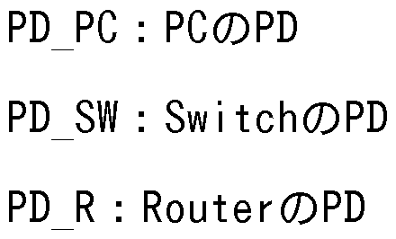
丁卩巳—卩〇— 1_ :卩〇の 1_〇9_1031 〇6 _106レイヤの丁卩巳
丁卩巳—卩〇—巳:卩〇の [1;116「门61;レイヤの丁卩巳
丁卩巳 卩〇 1卩:卩〇の 1卩レイヤの丁卩£
丁卩巳— !!!/— 1_ : 8¾\/_|1;(;11の1_〇9_1〇31· 〇6 _1〇6レイヤの丁卩巳
丁卩巳— !!!/—巳: 丨 1x11の [1;116「门61;レイヤの丁卩巳
丁卩巳—(¾—!_0 :(¾01^6「の 1_〇9 _108 I 〇6 _106レイヤの丁卩巳
丁卩巳—(¾—巳:(¾01^6「の [1;116「门61;レイヤの丁卩巳


— [¾ : [¾01^6「の
[0056] (^〇_ )

1^X0 (¾ 1卩:(¾〇1^6「の 1卩レイヤの 1^(X
(1\1 )

ド(^1\1(:一卩〇卩〇一 1卩:卩〇〜卩〇間の 1卩レイヤのド[^(1\1
[0057] 図 1 4は、 登録された 3 6〇における関係性の一例を表形式で示す図である 登録された 3 6〇は、 図 1 4に示される上下レイヤの関係性を有するものと する。
1卩レイヤ、 巳1;116「门61;レイヤ、 1〇9 I 0^ I 〇6 _106レイヤ、 および物理レイヤに おける 3 60の関係性は下記の (1) 〜 (1 3) の通りである。 下記 (1) 〜 (1 3) のうち、 (1) は経路の始点に、 (1 3) は経路の終点にそれぞれ 対応する。
[0058] ( 1)
(1卩レイヤ) 、 (巳1;116「门61;レイヤ) 、 および (1〇9 I 0& I 〇6 _106レイヤ)
:なし
(物理レイヤ) :卩 卩〇
[0059] (2)
(IPレイヤ) : TPE PC IP
(Ethernel;レイヤ) : TPE PC E
(Logical Dev iceレイヤ) : TPE— PC— LD
(物理レイヤ) : PP一 PC
[0060] (3)
(IPレイヤ (上位) ) : FRENC— PC-PC— IP
(IPレイヤ (下位) ) : FRELC— PC-R— IP
(Ethernetレイヤ (上位) ) : FRENC— PC-R— E
(Ethernetレイヤ (下位) ) : FRELC— PC-SW E
(Logical Dev iceレイヤ) : TL PC-SW
(物理レイヤ) : PL一 PC-SW
[0061] (4)
(IPレイヤ (上位、 下位) ) (Ethernetレイヤ (上位) ) :上記 (3) と同じ
(Ethernetレイヤ (下位) ) : TPE SW E
(Logical Dev iceレイヤ) : TPE SW LD
(物理レイヤ) : PP一 SW
[0062] (5)
(IPレイヤ (上位、 下位) ) (Ethernetレイヤ (上位) ) :上記 (3) と同じ
(Ethernetレイヤ (下位) ) : FREXC— SW E
(Logical Dev iceレイヤ) : NFD SW
(物理レイヤ) : PD_SW
(6)
上記 (4) と同じ
[0063] (7)
(IPレイヤ (上位、 下位) ) (Ethernetレイヤ (上位) ) :上記 (3)
と同じ
(Ethernetレイヤ (下位) ) : FRELC— SW-SW E
(Logical Dev iceレイヤ) : TL SW-SW
(物理レイヤ) : PL— SW-SW
[0064] (8)
上記 (4) と同じ
(9)
上記 (5) と同じ
(1 0)
上記 (4) と同じ
[0065] (1 1)
(IPレイヤ (上位、 下位) ) (Ethernetレイヤ (上位) ) :上記 (3) と同じ
(Ethernetレイヤ (下位) ) : FRELC— SW-R E
(Logical Dev iceレイヤ) : TL SW-R
(物理レイヤ) : PL— SW-R
[0066] (1 2)
(IPレイヤ (上位) ) : FRENC一 PC-PC一 IP (上記 (3) と同じ)
(IPレイヤ (下位) ) : TPE— R— IP
(Ethernetレイヤ) : TPE R E
(Logical Dev iceレイヤ) : TPE R LD
(物理レイヤ) : PP一 R
[0067] (1 3)
(IPレイヤ (上位) ) : FRENC一 PC-PC一 IP (上記 (3) と同じ)
(IPレイヤ (下位) ) : FREXC— R— IP
(Ethernetレイヤ) :なし
(Logical Dev iceレイヤ) : NFD R
(物理レイヤ) : PD R
〇 2020/175478 20 卩(:171? 2020 /007501
[0068] 図 1 5、 図 1 6、 および図 1 7は、 物理エンティティの登録の一例を示す 図である。
上記登録された物理レイヤの
 を用いて、 オペレータにより物理エンテ ィティが

[0069] 図 1 5では、 物理レイヤの 3 6〇を用いて登録される物理エンティティ情報 の対応関係を示す。
図 1 5に示された物理エンティティは図 1 6に示された形式で表記される とする。 また、 それぞれのエンティティ間の接続関係を相互に有するとする 図 1 7に示されるように物理エンティティが事前準備として

に登録されたとする。 3 6〇との対応関係は図 1 5に倣うとする。
[0070] 図 1 5に示される、 利用される 3 6〇と登録される物理エンティティとの関 係、 および図 1 6で対応する表記を下記の (3) 〜 (㊀) に示す。
(3)
(利用される 3 6〇)

(登録される物理エンティティ) ?〇]
(物理エンティティの表記)
 」 エン ティティ
[0071] ㈤
(利用される 3 6〇)

(登録される物理エンティティ)

(物理エンティティの表記)
 (:1_?1」 エ ンテイテイ
[0072] (〇)
(利用される 3 6〇) 卩 〇
(登録される物理エンティティ) 卩(:1-31«1_?1_
(物理エンティティの表記)
 (:1-31«1 卩し」 エンテイテイ
[0073] (d)
(:1-31«1 卩し」 エンテイテイ
[0073] (d)
(利用される Spec) PP_SW
(登録される物理エンティティ) Switch1_P1
(物理エンティティの表記) 「PP_SW」 Specが用いられた 「Switch1_P1
」 エンティティ
[0074] (e)
(利用される Spec) PD_SW
(登録される物理エンティティ) Switchl
(物理エンティティの表記) rPD_SWj Specが用いられた 「Switchl」 エンティティ
[0075] 次に始点情報および終点情報の指定について説明する。 図 1 8は、 始点情 報および終点情報の指定の一例を説明する図である。
オペレータが、 管理対象ネッ トワークについて Entity DB 1 2に格納される 物理エンティティの 「PC1」 を経路の始点と指定し、 物理エンティティの 「PC 2」 を経路の終点と指定する。 経路選択部 1 1は、 それぞれのエンティティを 始点および終点として記録する。
[0076] 次に経路選択について説明する。
経路選択部 1 1は、 物理エンティティ同士の接続関係を迪り、 始点から終 点までひと筆書きで迪り着ける経路を選択し、 選択結果として物理エンティ ティ (PP/PL/PD) を Entity DB1 2から取得する。
ここでは、 上記の経路 rPC1 ®Swi tch1 ®Swi tch2®Router®Swi tch4®Swi tc h6®PC2j に対応する順番の経路が選択されたものとする。 ここで PPおよび PL の記載は省略する。
[0077] 次に経路入力について説明する。 図 1 9は、 経路入力の一例を示す図であ る。
経路選択部 1 1は、 取得した経路に対応する物理エンティティ (PP/PL/PD ) をエンティティ補完部 1 3に入力する。
[0078] 次に Spec取得について説明する。
\¥02020/175478 22 卩(:17 2020 /007501
エンティティ補完部 1 3は、 入力された物理エンティティを元に、 Spec DB 1 4から論理エンティティの Specを下記の (1 ) 〜 (8) のように取得する
(1 ) エンティティ補完部 1 3は、 PPの Specの上位レイヤとして定義さ れている TPEの Specを Spec DB 1 4から取得する。
具体的には、 物理エンティティ rPC1_P1J は Spec rpp PCj に基づいている ため、 エンティティ補完部 1 3は、 この Spec rpp PCJ の上位に定義された 「 TPE_PC_LD」 を Spec DB1 4から取得する。
同様に、 エンティティ補完部 1 3は、 Switch1/2/4/6の各 PPの Spec 「PP_SW 」 の上位である 「TPE_SW_LD」 と、 Routerの PPの Spec 「PP_R」 の上位である Sp ec 「TPE_R_LD」 とを Spec DB1 4からそれぞれ取得する。
[0079] (2) エンティティ補完部 1 3は、 ( 1 ) で取得した TPE Specのさらに 上位レイヤとして定義されている TPE Specがある場合、 この TPE Specも Spec DB1 4から繰り返し取得する。
具体的には、 エンティティ補完部 1 3は、 (1 ) で取得した、 Logical Dev iceレイヤの上位の全ての Specを、 Spec DB 1 4に繰り返しアクセス (access ) することで取得する。
取得対象は 「TPE_PC_E」 , 「TPE_PC_IP」 , 「TPE_SW_E」 , 「TPE_R_E」 および 「TPE_R_IP」 である。
[0080] (3) エンティティ補完部 1 3は、 PLの Specの上位レイヤとして定義さ れている TLの Specを Spec DB 1 4から取得する。
具体的には、 物理エンティティ rPC1-SW1_PLj は Spec 「PL_PC-SW」 に基づ いているため、 エンティティ補完部 1 3は、 この rPL_PC-SWj Specの上位に 定義された 「TL_PC-SW」 を Spec DB1 4から取得する。
同様に、 エンティティ補完部 1 3は、 Swi tch〜 Swi tch間、 および Switch〜 R outer間の物理エンティティ PLの Specの上位に定義された 「TL_SW-SW」 および 「TL_SW-R」 を Spec DB1 4から取得する。
[0081] (4) エンティティ補完部 1 3は、 (3) で取得した丁!_ 3 6〇の上位レイ
ヤとして定義されている FRE(LC)の Specを Spec DB 1 4から取得する。
具体的には、 エンティティ補完部 1 3は、 (3) で取得した、 Logical Dev iceレイヤの上位の全ての Specを、 Spec DB 1 4に繰り返しアクセスすること で取得する。
取得対象は 「FRELC_PC-SW_E」 , 「FRELC_SW-SW_E」 および 「FRELC_SW-R_E」 である。
[0082] (5) エンティティ補完部 1 3は、 PDの Specの上位レイヤとして定義さ れている NFDの Specを Spec DB 1 4から取得する。
具体的には、 物理エンティティ 「Switchl」 は Spec 「PD_SW」 に基づいてい るため、 エンティティ補完部 1 3は、 この Spec rPD_SWj の上位に定義された 「NFD_SW」 を Spec DB 1 4から取得する。
同様に、 エンティティ補完部 1 3は、 Routerの Spec 「PD_R」 の上位である S pec 「NFD_R」 を Spec DB 1 4から取得する。
(6) エンティティ補完部 1 3は、 (5) で取得した NFD Specの上位レ イヤとして定義されている FRE(XC)の Specを Spec DB 1 4から取得する。
具体的には、 エンティティ補完部 1 3は、 (5) で取得した Logical Devic eレイヤの上位の全ての Specを、 Spec DB 1 4に繰り返しアクセスすることで 取得する。
取得対象は 「FREXC_SW_E」 「FREXC_R_IP」 である。
[0083] (7) エンティティ補完部 1 3は、 (4で) 取得した FRE(LC)および (6
) で取得した FRE (XC)の Specの上位に定義されている FRE(NC)の Specを Spec D B 1 4から取得する。
具体的には、 エンティティ補完部 1 3は、 取得した Specのうち、 Ethernet レイヤの Specである 「FRELC— PC-SW— E」 , 「FRELC— SW-SW— E」 および 「FREXC— SW _Ej を組み合わせた 「FRENC_PC-R_E」 を Spec DB 1 4から取得する。
(8) エンティティ補完部 1 3は、 (7) で取得した FRE(NC)のさらに上 位レイヤとして定義されている FRE(LC)がある場合、 この FRE(LC) Specを Spec DB1 4から取得し、 さらに上記 (4) を実行する。 FRE(NC)の上位に定義さ
れている FRE(LC)が無くなったら、 エンティティ補完部 1 3は、 Spec取得にか かる処理を終了する。
[0084] 具体的には、 エンティティ補完部 1 3は、 (7) で取得した Spec 「FRENC_P C-R_Ej の上位に定義された 「FRELC_PC-R_IP」 を Spec DB 1 4から取得する。 さらに、 エンティティ補完部 1 3は、 取得した 「FRELC_PC-R_IP」 と (6) で取得した 「FREXC_R_IP」 とを組み合わせて 「FRENC_PC-PC_IP」 を Spec DB 1 4から取得する。
以上により、 上位に定義された Specが存在しないため、 Spec取得にかかる 処理が終了する。
[0085] 次に、 エンティティ生成について説明する。
エンティティ補完部 1 3は、 上記取得した Spec群に対して、 論理レイヤの エンティティを下位のレイヤから順に下記の (1) 〜 (7) のように生成し て Ent i ty DB 1 2へ格納する。
(1) エンティティ補完部 1 3は、 Log i ca l Dev i ceレイヤの TPEを生成す る。 この生成の際には、 エンティティ補完部 1 3は、 物理エンティティ PPへ の関連性を示す情報を内部メモリに保持する。
[0086] 図 2 0、 および図 2 1は、 Log i ca l Dev i ceレイヤの TPEの生成の一例を示す 図である。
具体的には、 エンティティ補完部 1 3は、 取得した、 Log i ca l Dev i ceレイ ヤの Specに対し、 図 2 0に示されるように TPEエンティティを生成する。 生成 の一部の図示は省略する。
各 TPEエンティティは、 図 2 0の最下行に示される PPエンティティへの関連 性を有する。 最終的に、 エンティティ補完部 1 3は、 図 2 1 に示される 1 2 個の TPEエンティティを生成する。
[0087] 図 2 0に示される、 「利用される Spec」 、 「生成する Log i ca l Dev i ceレイ ヤの TPEエンティティ」 、 および 「関連性を有する物理エンティティ」 の対応 の例は下記の (a) 〜 (d) のとおりである。
( a )
(利用される 3 6〇)

(生成される 1_〇9_103[ 6 _106レイヤの丁 £エンティティ) 01 1 1_ 丁卩
£
(関連性を有する物理エンティティ)

[0088] (匕)

丁卩£
(関連性を有する物理エンティティ)
 _?1
_?1
[0089] (〇)
(利用される 3 6〇)

(生成されるし〇9 _108 I 6 _106レイヤの丁卩巳エンティティ) 31/^1x111 卩2 1_ 丁卩£
(関連性を有する物理エンティティ)

[0090] (〇〇
(利用される Spec) TPE R LD
(生成される Log i ca I Dev i ceレイヤの TPEエンティティ) Router P1 LD
TPE
(関連性を有する物理エンテイテイ) Router P1
[0091] 図 21中の a , b , c , d , e , および f の意味は下記のとおりである。
(a) 「TPE_PC_LD」 Specが用いられた 「PC1_P1 _LD_TPE」 エンテイテイ
(b) 「PC1_P1_LD_TPE」 エンテイテイは 「PC1_P1」 エンテイテイへの関 連性を有する。
(c) 「TPE— SW LD」 Specが用いられた 「Swtichl P1 LD TPE」 エンテイ

( f ) 本処理のプロセス (process) により生成される TPEエンティティ [0092] (2) エンティティ補完部 1 3は、 Logical Deviceレイヤの TLを生成す る。 この生成の際には、 エンティティ補完部 1 3は、 Logical Dev iceレイヤ の TPEへの関連性を示す情報を内部メモリに保持する。
図 22、 図 23は、 Logical Deviceレイヤの TLの生成の一例を示す図であ る。 具体的には、 エンティティ補完部 1 3は、 取得した Logical Deviceレイ ヤの Specに対し、 図 22に示されるように TLエンティティを生成する。 生成 の一部の図示は省略する。
各 TLエンティティは、 図 22の最下行に示される、 Logical Dev iceレイヤ の TPEエンティティへの関連性を有する。 最終的に、 エンティティ補完部 1 3 は、 図 23に示される 6個の TLエンティティを生成する。
[0093] 図 23に示される、 「利用される Spec」 、 「生成される Log i ca I Deviceレ イヤの TLエンティティ」 、 および 「関連性を有する Logical Deviceレイヤの T PEエンティティ」 の対応の例は下記の (a) 〜 (c) のとおりである。
(a)
(利用される Spec) TL_PC-SW
(生成される Log i ca I Dev i ceレイヤの TLエンティティ) PC1-Swi tch1 T L
(関連性を有する Logical Dev i ceレイヤの TPEエンティティ) PC1 P1 L D TPE、 Switchl P1 LD TPE
[0094] (b)
(利用される Spec) TL_SW-SW
(生成される Log i ca l Dev i ceレイヤの TLエンティティ) Swi tch1-Swi tc h2 TL
(関連性を有する Log i ca L Dev i ceレイヤの TPEエンティティ) Swi tch1 P2 LD TPE、 Switch2 P1 LD TPE
[0095] (c)
(利用される Spec) TL_SW-R
(生成される Log i ca I Dev i ceレイヤの TLエンティティ) Swi tch2-Route r TL
(関連性を有する Log i ca L Dev i ceレイヤの TPEエンティティ) Swi tch2 P2 LD TPE、 Router P1 LD TPE
[0096] 図 23中の a, b, c, d, および eの意味は下記のとおりである。
(a) 「TPE_PC-SW」 Specが用いられた 「PC1-Swi tch1_TL」 エンティティ
( b) rPC1-Switch1 TLJ エンテイテイは 「PC1— P1— LD TPE」 エンテイテ ィおよび 「Switch1_P1_LD_TPE」 エンティティへの関連性を有する。
(c) 「TL— SW-SW」 Specが用いられた 「Swi tch1-Swi tch2— TL」 エンティ ティ
(d) 「TL— SW-R」 Specが用いられた 「Swi tch2-Router— TL」 エンティテ イ
(e) 本処理のプロセスにより生成される TLエンティティ
[0097] (3) エンティティ補完部 1 3は、 Logical Dev i ceレイヤの NFDを生成す る。 この生成の際には、 エンティティ補完部 1 3は、 Logical Dev iceレイヤ の TPEへの関連性を示す情報を内部メモリに保持する。
図 24および図 25は、 Logical Dev i ceレイヤの NFDの生成の一例を示す図 である。
具体的には、 エンティティ補完部 1 3は、 取得した Logical Deviceレイヤ の Specに対し、 図 24に示されるように NFDエンティティを生成する。 生成の —部の図示は省略する。
各 NFDエンティティは、 図 24の最下行に示される、 Logical Dev iceレイヤ の TPEエンティティへの関連性を有する。 最終的に、 エンティティ補完部 1 3 は、 図 25に示される 5個の NFDエンティティを生成する。
[0098] 図 24に示される、 「利用される Spec」 、 「生成される Logical Deviceレ イヤの NFDエンティティ」 、 および 「関連性を有する Logical Deviceレイヤの
TPEエンティティ」 の対応の例は下記の (a) , (b) , および (c) のとお りである。
(a)
(利用される Spec) NFD_SW
(生成される Log i ca I Dev i ceレイヤの NFDエンティティ) Sw i tch1 NFD (関連性を有する Log i ca L Dev i ceレイヤの TPEエンティティ) Sw i tch1 P1 LD TPE、 Sw i tchl P2 LD TPE
[0099] (b)
(利用される Spec) NFD_SW
(生成される Log i ca l Dev i ceレイヤの NFDエンティティ) Sw i tch2 NFD (関連性を有する Log i ca L Dev i ceレイヤの TPEエンティティ) Sw i tch2 P1 LD TPE、 Sw i tch2 P2 LD TPE
[0100] (c)
(利用される Spec) NFD R
(生成される Log i ca I Dev i ceレイヤの NFDエンテイテイ) Router NFD (関連性を有する Log i ca L Dev i ceレイヤの TPEエンティティ) Router P 1 LD TPE、 Router P2 LD TPE
[0101 ] 図 2 5中の a , b , c , d , および eの意味は下記のとおりである。
(a) 「NFD_SW」 Specが用いられた 「Sw i tch1_NFD」 エンティティ
( b) 「Sw i tchl NFD」 エンテイテイは 「Sw i tch1 P1 LD TPE」 エンテイ ティおよび 「Sw i tch1_P2_LD_TPE」 エンティティへの関連性を有する。
(c) 「NFD— SW」 Specが用いられた 「Sw i tch2— NFD」 エンティティ ( d) 「NFD— R」 Specが用いられた 「Router— NFD」 エンテイテイ (e) 本処理のプロセスにより生成される NFDエンティティ
[0102] (4) エンティティ補完部 1 3は、 論理レイヤの TPEを生成する。 この生 成の際には、 エンティティ補完部 1 3は、 下位の論理レイヤの
 への関連性 を示す情報を内部メモリに保持する。
図 2 6、 および図 2 7は、 論理レイヤの
 の生成の一例を示す図である。
具体的には、 エンティティ補完部 1 3は、 Logical Dev i ceレイヤの上位の Eth ernetレイヤの Specに対し、 図 26に示される TPEエンティティを生成する。 生成の一部の図示は省略する。
の生成の一例を示す図である。
具体的には、 エンティティ補完部 1 3は、 Logical Dev i ceレイヤの上位の Eth ernetレイヤの Specに対し、 図 26に示される TPEエンティティを生成する。 生成の一部の図示は省略する。
各丁 エンティティは、 図 26の最下行に示される、 下位の

レイヤの
 エンティティへの関連性を有する。 最終的に、 エンティティ補完 咅^1 3は、
 エンティティを生成する。
[0103] 図 26に示される、 「利用される 3 6〇」 、 「生成される 1;1161^61;レイヤの丁

ティティ」 の対応の例は下記の (3) , (13) , (〇) , および (〇1) のと おりである。
(3)
(利用される 3 6〇)

(生成される
 レイヤの丁卩巳エンティティ) 卩 卩1 巳 丁卩£ (関連性を有する
 エンティティ) ?01
 1 丁卩£
1 丁卩£
[0104] (b)
(利用される 3 6〇)

(生成される
 レイヤの丁卩巳エンティティ) Swi 1(^1一卩1一巳一丁卩£

[0105] (〇)
(利用される 3 6〇)

(生成される
 レイヤの丁卩巳エンティティ) Swi 1(^1 卩2 巳 丁卩£

[0106] ⑷
 (関連性を有する Log i ca L Dev i ceレイヤの TPEエンティティ) Router P 1 LD TPE
[0107] 図 27中の a, b, c, d, e, および f の意味は下記のとおりである。
(a) 「TPE_PC_E」 Specが用いられた 「PC1_P1_E_TPE」 エンティティ
(b) 「PC1_P1_E_TPE」 エンティティは 「PC1_P1_LD_TPE」 エンティティ への関連性を有する。
(c) 「TPE_SW_E」 Specが用いられた 「Swt i ch1_P1_E_TPE」 エンティテ イ
(d) 「TPE_SW_E」 Specが用いられた 「Swt i ch1_P2_E_TPE」 エンティテ イ
( e ) rTPE R Ej Specが用いられた 「Router_P1_E_TPE」 エンティティ (f ) 本処理のプロセスにより生成される TPEエンティティ
[0108] (5) エンティティ補完部 1 3は、 論理レイヤの FRE(LC)を生成する。 こ の生成の際には、 エンティティ補完部 1 3は、 該当レイヤの TPEへの関連性を 示す情報を内部メモリに保持する。
図 28および図 29は、 論理レイヤの FRE(LC)の生成の一例を示す図である 。 具体的には、 エンティティ補完部 1 3は、 Logical Dev i ceレイヤの上位の E the r netレイヤの Specに対し、 図 28に示される FRE(LC)エンティティを生成 する。 生成の _部の図示は省略する。 各 FRE(LC)エンティティは、 図 28の最 下行に示される Ethernetレイヤの TPEエンティティへの関連性を有する。 最終 的に、 エンティティ補完部 1 3は、 図 29に示される 6個の FRE(LC)エンティ ティを生成する。
[0109] 図 28に示される、 「利用される Spec」 、 「生成される Ethernetレイヤの F RE(LC)エンティティ」 、 および 「関連性を有する Ethernetレイヤの TPEエンテ ィティ」 の対応の例は下記の (a) , (b) , および (c) の通りである。
(a)
(利用される Spec) FRELC PC-SW E
(生成される
 PC1 -Switchl E
FRELC
(関連性を有する
 PC1 P1 E TPE、
Switchl P1 E TPE
[0110] ㈤

Switchl P2 E T

[0111] (〇)

Switch2 P2 E T

[0112] 図 29中の 1〇, 〇, ¢1, および㊀の意味は下記の (8) 〜 (㊀) のと おりである。
(a)
 卩㊀〇が用いられた
 ェ ン丁イテイ
(匕)
 ド(^1_(:」 エンテイテイは 「卩(:1—卩1— 丁卩 」 エンテ イテイおよび 「31«4(;111_?1_£_丁?£」 エンテイテイへの関連性を有する。
(〇)
 卩㊀〇が用いられた

」 エンテイテイ
(〇〇

エンテイテイ
(ø) 本処理のプロセスにより生成されるド(^〇_ エンティティ [0113] (6) エンティティ補完部 1 3は、 論理レイヤの 1^(X0を生成する。 こ
の生成の際には、 エンティティ補完部 1 3は、 該当レイヤの TPEへの関連性を 示す情報を内部メモリに保持する。
図 30、 および図 3 1は、 論理レイヤの FRE(XC)の生成の一例を示す図であ る。 具体的には、 エンティティ補完部 1 3は、 Logical Dev iceレイヤの上位 の Ether netレイヤの Specに対し、 図 30に示される FRE(XC)エンティティを生 成する。 生成の一部の図示は省略する。
各 FRE(XC)エンティティは、 図 30の最下行に示される Ethernetレイヤの TP Eエンティティへの関連性を有する。 最終的に、 エンティティ補完部 1 3は、 図 3 1 に示される 4個の FRE(XC)エンティティを生成する。
[0114] 図 30に示される、 「利用される Spec」 、 「生成される Ethernetレイヤの F RE(XC)エンティティ」 および 「関連性を有する Ethernetレイヤの TPEエンティ テイ」 の対応の例は下記の (a) , (b) , および (c) の通りである。
(a)
(利用される 3 6〇)

(生成される
 Swi
Swi

0
レイヤの丁卩巳エンティティ) Swi 1 1_卩1_£_丁

[0115] (b)
(利用される 3 6〇)

(生成される

C
(関連性を有する Ethernetレイヤの TPEエンテイテイ) Swi tch2 P1 E T PE、 Switch2 P2 E TPE
[0116] (c)
(利用される Spec) FREXC_SW_E
(生成される Ethernetレイヤの FRE(XC)エンテイテイ) Swi tch6 E FREX
C
〇 2020/175478 33 卩(:171? 2020 /007501
(関連性を有する巳1;116「门61;レイヤの丁卩巳エンティティ) 丨 1;〇116_?1_£_丁

[0117] 図 3 1 中の 1〇, 〇, ¢1, および㊀の意味は下記の (8) 〜 (㊀) のと おりである。
(a)
 卩㊀〇が用いられた 「3|«4(^1_£_ド[^乂(:」 エンティテ イ
(匕)
 エンテイテイは
 エンテ ィティおよび 「31«1 111_?2_£_丁?£」 エンティティへの関連性を有する。
(〇)
 卩㊀〇が用いられた
 エンティテ イ
(〇〇
 卩㊀〇が用いられた
 エンティテ イ
(ø) 本処理のプロセスにより生成される 1^(X エンティティ
[0118] (7) エンティティ補完部 1 3は、 論理レイヤのド(^〇\1〇を生成する。 こ の生成の際には、 エンティティ補完部 1 3は、 該当レイヤの への関連性を 示す情報を内部メモリに保持する。
図 32および図 33は、 論理レイヤのド(^〇\1 の生成の一例を示す図である 。 具体的には、 エンティティ補完部 1 3は、 1_〇9_1081 〇6 _106レイヤの上位の巳 1:1161^61;レイヤの 3 6〇に対し、 図 32に示されるド[^(1\1 エンティティを生成 する。
各ド(^〇\1 エンティティは、
 レイヤの丁卩 £エンティティへの関連性を有する。 最終的に、 エンティティ補完部 1 3は、 図 33に示される 2個のド(^〇\1 エンティティを生成する。
[0119] 図 32に示される、 「利用される 3 60」 、 「生成される 1;1161^61;レイヤのド (^〇\1〇エンティティ」 、 および 「関連性を有する
 レイヤの
レイヤの
 エンテ ィティ」 の対応の例は下記の (3) および (13) のとおりである。
(3)
(利用される 3 6〇)
 F
F

[0120] ㈤

[0121 ] 図 3 3中の 13 , 〇, および ¢1の意味は下記の (3) 〜 (〇1) のとおり である。

ティティ
(匕) 「卩(:1 -[¾〇1^6「— [^ 」 エンテイテイは 「卩(:1—卩1— 丁卩 」 エンテ イテイおよび
 エンテイテイへの関連性を有する。
(〇)
 「 1^6「-?02 £ ド(^1\1(:」 エン 丁ィ丁ィ
(d) 本処理のプロセスにより生成される FRE(NC)エンティティ [0122] 次に、 2回目の上記 (4) について説明する。 ここではエンティティ補完 部 1 3は、 論理レイヤの TPEを生成する。 この生成の際には、 エンティティ補 完部 1 3は、 下位の論理レイヤの TPEへの関連性を示す情報を内部メモリに保 持する。
図 3 4および図 3 5は、 論理レイヤの TPEの生成の一例を示す図である。 具体的には、 エンティティ補完部 1 3は、 Ethe rnetレイヤの上位の IPレイ ヤの Specに対し、 図 3 4に示される TPEエンティティを生成する。
各 TPEエンティティは、 図 3 4の最下行に示される Ethe r netレイヤの TPEエ ンティティへの関連性を有する。 最終的に、 エンティティ補完部 1 3は、 図
3 5に示される
 エンティティを生成する。
[0123] 図 3 4に示される、 「利用される Spec」 、 「生成される IPレイヤの TPEエン ティティ」 、 および 「関連性を有する Ethernetレイヤの TPEエンティティ」 の 対応の例は下記の (a) , (b) , (c) , および (d) のとおりである。
(a)
(利用される Spec) TPE PC IP
(生成される IPレイヤの TPEエンティティ) PC1 P1 IP TPE (関連性を有する Ethernetレイヤの TPEエンティティ) PC1 P1 E TPE [0124] (b)
(利用される Spec) TPE R IP
(生成される IPレイヤの TPEエンティティ) Router P1 IP TPE (関連性を有する Ethernetレイヤの TPEエンティティ) Router P1 E TP E
[0125] (c)
(利用される Spec) TPE R IP
(生成される IPレイヤの TPEエンティティ) Router P2 IP TPE (関連性を有する Ethernetレイヤの TPEエンティティ) Router P2 E TP E
[0126] (d)
(利用される Spec) TPE PC IP
(生成される IPレイヤの TPEエンティティ) PC2 P1 IP TPE (関連性を有する Ethernetレイヤの TPEエンティティ) PC2 P1 E TPE [0127] 図 3 5中の a , b , c , および dの意味は下記の (a) 〜 (d) のとおり である。
(a) 「TPE— PC— IP」 Specが用いられた 「PC1— P1— IP— TPE」 エンティティ
(b) 「PC1— P1— IP— TPE」 エンティティは 「PC1— P1— E— TPE」 エンティティ への関連性を有する。
(c) 「TPE_R_IP」 Specが用いられた 「Route P1_IP_TPE」 エンティテ
イ
(d) 本処理のプロセスにより生成される TPEエンティティ
[0128] 次に、 2回目の上記 (5) について説明する。 ここではエンティティ補完 部 1 3は、 論理レイヤの FRE(LC)を生成する。 この生成の際には、 エンティテ ィ補完部 1 3は、 該当レイヤの TPEへの関連性を示す情報を内部メモリに保持 する。
図 3 6、 および図 3 7は、 論理レイヤの FRE(LC)の生成の一例を示す図であ る。
具体的には、 エンティティ補完部 1 3は、 Ethernetレイヤの上位の IPレイ ヤの Specに対し、 図 3 6に示される FRE(LC)エンティティを生成する。
各 TPEエンティティは、 図 3 6の最下行に示される IPレイヤの TPEエンティ ティへの関連性を有する。 最終的に、 エンティティ補完部 1 3は、 図 3 7に 示される 2個の FRE(LC)エンティティを生成する。
[0129] 図 3 6に示される、 「利用される Spec」 、 「生成される IPレイヤの FRE(LC) エンティティ」 、 および 「関連性を有する IPレイヤの TPEエンティティ」 の対 応の例は下記の (a) 、 および (b) のとおりである。
(a)
(利用される Spec) FRELC PC-R IP
(生成される IPレイヤの FRE(LC)エンティティ) PC1 -Router IP FRELC
(関連性を有する IPレイヤの TPEエンティティ) PC1 P1 IP TPE, Route r P1 IP TPE
[0130] (b)
(利用される Spec) FRELC PC-R IP
(生成される IPレイヤの FRE(LC)エンティティ) Router-PC2 IP FRELC
(関連性を有する IPレイヤの TPEエンティティ) Router P2 IP TPE, PC 2 P1 IP TPE
[0131 ] 図 3 7中の a , b , c , および dの意味は下記の (a) 〜 (d) のとおり である。
\¥02020/175478 37 卩(:17 2020 /007501

ンティティ
(匕) 「卩01-[¾〇1^6「 1卩 ド(^1_0」 エンテイテイは 「卩01—卩1— 1卩—丁卩 」 エン ティティおよび 「1^01^6
 エンティティへの関連性を有する。
(〇) 「ド(^1_ 〇 :^」 3 6〇が用いられた 「 1^6「-?02—:^—ド(^1_(:」 エ ンティティ
( ) 本処理のプロセスにより生成されるド(^〇_ エンティティ [0132] 次に、 2回目の上記 (6) について説明する。 ここではエンティティ補完 部 1 3は、 論理レイヤの 1^(X を生成する。 この生成の際には、 エンティテ ィ補完部 1 3は、 該当レイヤの
 への関連性を示す情報を内部メモリに保持 する。
図 38および図 39は、 論理レイヤの 1^(X の生成の一例を示す図である 具体的には、 エンティティ補完部 1 3は、
 レイヤの上位の レイ ヤの 3 6〇に対し、 図 38に示される 1^(X エンティティを生成する。
各丁 £エンティティは、 図 38の最下行に示される レイヤの
 エンティ ティへの関連性を有する。 最終的に、 エンティティ補完部 1 3は、 図 39に 示される 1個の 1^(X エンティティを生成する。
[0133] 図 38に示される、 「利用される 3 6〇」 、 「生成される レイヤの 1^(X エンティティ」 、 および 「関連性を有する レイヤの
 エンティティ」 の対 応の例は下記の (3) のとおりである。
(3)
(利用される 3 60)

(生成される レイヤの 1^(X エンティティ)

〇

[0134] 図 39中の b , および〇の意味は下記の (8) 〜 (〇) のとおりであ る。
(a) 「FREXC— R— IP」 Specが用いられた 「Router— IP— FREXC」 エンティテ イ
( b) 「Router— IP— FREXC」 エンテイテイは 「Router— P1— IP— TPE」 エンテ ィティおよび 「Router_P2_IP_TPE」 エンティティへの関連性を有する。
(c) 本処理のプロセスにより生成される FRE(XC)エンティティ [0135] 次に、 2回目の上記 (7) について説明する。 ここではエンティティ補完 部 1 3は、 論理レイヤの FRE(NC)を生成する。 この生成の際には、 エンティテ ィ補完部 1 3は、 該当レイヤの TPEへの関連性を示す情報を内部メモリに保持 する。
図 40、 図 4 1は、 論理レイヤの FRE(NC)の生成の一例を示す図である。 具体的には、 エンティティ補完部 1 3は、 Ethernetレイヤの上位の IPレイ ヤの Specに対し、 図 40に示される FRE(NC)エンティティを生成する。
各 TPEエンティティは、 図 40の最下行に示される IPレイヤの TPEエンティ ティへの関連性を有する。 最終的に、 エンティティ補完部 1 3は、 図 4 1 に 示される 1個の FRE(NC)エンティティを生成する。
[0136] 図 40に示される、 「利用される Spec」 、 「生成される IPレイヤの FRE(NC) エンティティ」 、 および 「関連性を有する IPレイヤの TPEエンティティ」 の対 応の例は下記の (a) のとおりである。
(a)
(利用される Spec) FRENC PC-PC IP
(生成される IPレイヤの FRE (NC)エンティティ) PC1-PC2 IP FRENC (関連性を有する IPレイヤの TPEエンティティ) PC1 P1 IP TPE, PC2 P 1 IP TPE
[0137] 図 4 1中の a, b, および cの意味は下記の (a) 〜 (c) のとおりであ る。
(a) 「FRENC一 PC-PC一 IP」 Specが用いられた 「PC1-PC2一 IP一 FRENC」 エン ティティ
( b) 「PC1-PC2 IP FRENC」 エンテイテイは 「PC1— P1 IP TPE」 エンテイ
ティおよび 「PC2_P1_IP_TPE」 エンティティへの関連性を有する。
( c ) 本処理のプロセスにより生成される FRE (NC)エンティティ
2回目の上記 ( 7 ) のを実施後、 IPレイヤのさらに上位のレイヤが存在し ないことから、 エンティティ補完部 1 3は、 エンティティ補完 (生成) 処理 を終了する。
[0138] 次に、 エンティティ補完処理を含む、 ネッ トワーク管理システム 1 0によ る各種処理の実施後のネッ トワークの状態について説明する。
図 4 2は、 ネッ トワーク管理システムによる各種処理の実施後のネッ トワ —クの状態の一例を示す図である。
図 4 2に示されるように、 ネッ トワーク管理システムによる各種処理の実 施後、 Ent i ty DB 1 2内に登録されたエンティティは、 合計 9 0個のエンティ ティである。
[0139] そのうち、 図 4 2中の aに示される、 物理情報として Ent i ty DB 1 2内に登 録された 「PD : 9個、 PP : 2 0個、 PL : 5個」 でなる合計 3 4個のエンティ ティはオペレータにより生成される。 また、 図 4 2中の bに示される 「TL :
6個、 NFD : 6個、 TPE : 2 8個、 FRE (NC) : 3個、 FRE (LC) : 8個、 FRE (XC) : 5個」 でなる合計 5 6個のエンティティはエンティティ補完部 1 3によって 生成される。
[0140] 図 4 3は、 本発明の一実施形態に係るネッ トワーク管理装置のハードウエ ア構成の一例を示すブロック図である。
図 4 3に示された例では、 上記の実施形態に係るネッ トワーク管理システ ム 1 0は、 例えばサーバコンピュータ (server computer) またはパーソナル コンビュータにより構成され、 C P U等のハードウエアプロセッサ (hardwar e processor) 1 1 1 Aを有する。 そして、 このハードウエアプロセッサ 1 1 1 Aに対し、 プログラムメモリ (prog ram memory) 1 1 1 B、 データメモリ (data memory) 1 1 2、 入出カインタフェース ( i nterface) 1 1 3及び通 信インタフェース 1 1 4が、 バス (bus) 1 2 0を介して接続される。
[0141 ] 通信インタフェース 1 1 4は、 例えば 1つ以上の無線の通信インタフェー
スユニッ トを含んでおり、 通信ネッ トワーク NWとの間で情報の送受信を可 能にする。 無線インタフエースとしては、 例えば無線 LAN (Local Area Ne twork) などの小電力無線データ通信規格が採用されたインタフエースが使用 される。
[0142] 入出カインタフエース 1 1 3には、 ネッ トワーク管理システム 1 0に付設 される、 オペレータ用の入カデバイス 50および出カデバイス 60が接続さ れる。
入出カインタフエ _ス 1 1 3は、 キーボード、 タッチパネル (touch pane I ) 、 タッチパッ ド (touchpad) 、 マウス (mouse) 等の入カデバイス 50を通 じてオペレータにより入力された操作データを取り込むとともに、 出カデー 夕を液晶または有機 E L (Electro Luminescence) 等が用いられた表示デバ イスを含む出カデバイス 60へ出力して表示させる処理を行なう。 なお、 入 カデバイス 50および出カデバイス 60には、 ネッ トワーク管理システム 1 0に内蔵されたデバイスが使用されてもよく、 また、 ネッ トワーク NWを介 してネッ トワーク管理システム 1 0と通信可能である他の情報端末の入カデ バイスおよび出カデバイスが使用されてもよい。
[0143] プログラムメモリ 1 1 1 巳は、 非一時的な有形の記憶媒体として、 例えば 、 H DD (Hard Disk Drive) または SS D (Solid State Drive) 等の随時 書込みおよび読出しが可能な不揮発性メモリ (non-vo lat i le memory) と、 R 〇 M等の不揮発性メモリとが組み合わせて使用されたもので、 一実施形態に 係る各種制御処理を実行する為に必要なプログラムが格納されている。
[0144] データメモリ 1 1 2は、 有形の記憶媒体として、 例えば、 上記の不揮発性 メモリと、 RAM (Random Access Memory) 等の揮発性メモリ (volatile me mory) とが組み合わせて使用されたもので、 各種処理が行なわれる過程で取 得および作成された各種データが記憶される為に用いられる。
[0145] 本発明の一実施形態に係るネッ トワーク管理システム 1 0は、 ソフトゥエ ア (software) による処理機能部として、 図 4などに示される経路選択部 1 1、 Entity DB 1 2、 エンティティ補完部 1 3、 および Spec DB 1 4を有する
データ処理装置として構成され得る。
[0146] Entity DB 1 2および Spec DB 1 4は、 図 43に示されたデータメモリ 1 1
2が用いられることで構成され得る。 ただし、 これらの領域はネッ トワーク 管理システム 1 0内に必須の構成ではなく、 例えば、 US B (Universal Ser ial Bus) メモリなどの外付け記憶媒体、 又はクラウド (cloud) に配置され たデータべースサーバ (database server) 等の記憶装置に設けられた領域で あってもよい。
[0147] 上記の処理機能部は、 いずれも、 プログラムメモリ 1 1 1 Bに格納された プログラムを上記ハードウエアプロセッサ 1 1 1 Aにより読み出させて実行 させることにより実現され得る。 なお、 これらの処理機能部の一部または全 部は、 特定用途向け集積回路 (AS I C (Application Specific Integrated Circuit) ) または F PGA (Field-Programmable Gate Array) などの集積 回路を含む、 他の多様な形式によって実現されてもよい。
[0148] 以上説明したように、 本発明の一実施形態に係るネッ トワーク管理システ ムでは、 エンティティに基づいて、 ネッ トワークの始点と終点との間の物理 レイヤの経路を選択する経路選択処理を行ない、 情報オブジェクトの仕様に 基づいて、 選択された物理レイヤの経路に対応する、 論理レイヤのエンティ ティを生成する。 これにより、 論理レイヤのエンティティの設定にかかる負 荷を軽減することができる。
[0149] また、 本発明の一実施形態に係るネッ トワーク管理システムでは、 物理レ イヤおよび最下層の論理レイヤとの間の関係性、 および最下層を含む複数の 層の論理レイヤの間の関係性がそれぞれ定義され、 この関係性に基づいて、 経路における物理レイヤに対応する各層の論理レイヤ仕様を取得する。 これ により、 エンティティの生成対象である各層の論理レイヤの仕様を適切に取 得することができる。
[0150] また、 本発明の一実施形態に係るネッ トワーク管理システムでは、 物理レ イヤの経路に対応する論理レイヤのエンティティが生成されるときに、 同じ 層又は 1つ下位の層のレイヤにおけるエンティティとの関係性が保持され、
この関係性に基づいて、 物理レイヤの経路に対応する、 各層の論理レイヤの ェンティティを生成する。 これにより、 物理レイヤに対応する、 各層の論理 レイヤのェンティティを適切に生成することができる。
[0151 ] また、 各実施形態に記載した手法は、 計算機 (コンピュータ) に実行させ ることができるプログラム (ソフトウェア手段) として、 例えば磁気ディス ク (フロッピー (登録商標) ディスク、 ハードディスク等) 、 光ディスク ( C D - R O M, D V D、 M O等) 、 半導体メモリ (R O M、 R A M、 フラッ シュメモリ等) 等の記録媒体に格納し、 また通信媒体により伝送して頒布す ることもできる。 なお、 媒体側に格納されるプログラムには、 計算機に実行 させるソフトウェア手段 (実行プログラムのみならずテーブル、 データ構造 も含む) を計算機内に構成させる設定プログラムをも含む。 本装置を実現す る計算機は、 記録媒体に記録されたプログラムを読み込み、 また場合により 設定プログラムによりソフトウェア手段を構築し、 このソフトウェア手段に よって動作が制御されることにより上述した処理を実行する。 なお、 本明細 書でいう記録媒体は、 頒布用に限らず、 計算機内部あるいはネッ トワークを 介して接続される機器に設けられた磁気ディスク、 半導体メモリ等の記憶媒 体を含むものである。
[0152] なお、 本願発明は、 上記実施形態に限定されるものではなく、 実施段階で はその要旨を逸脱しない範囲で種々に変形することが可能である。 また、 各 実施形態は可能な限り適宜組み合わせて実施してもよく、 その場合組み合わ せた効果が得られる。 更に、 上記実施形態には種々の段階の発明が含まれて おり、 開示される複数の構成要件における適当な組み合わせにより種々の発 明が抽出され得る。
符号の説明
[0153] 1 0 ネッ トワーク管理システム
1 1 経路選択部
1 2 ---Ent i ty DB
1 3 ェンティティ補完部
1 4 Spec DB
Claims
[請求項 1 ] ネッ トワークの情報オブジェクトの実体を表す第 1のエンティティ が記憶される第 1の記憶装置に記憶された前記第 1のエンティティに 基づいて、 前記ネッ トワークの始点と終点との間の物理レイヤの経路 を選択する経路選択処理を行なう経路選択処理部と、 前記情報オブジェクトの仕様が記憶される第 2の記憶装置に記憶さ れた前記仕様に基づいて、 前記経路選択処理部により選択された物理 レイヤの経路に対応する、 論理レイヤの第 2のエンティティを生成す るエンティティ生成処理を行なうエンティティ生成処理部と、 を備えるネッ トワーク管理装置。
[請求項 2] 前記第 2の記憶装置には、
前記物理レイヤおよび最下層の論理レイヤとの間の関係性、 およ び前記最下層を含む複数の層の論理レイヤ間の関係性を定義する情報 が、 前記情報オブジェクトの仕様として記憶され、 前記エンティティ生成処理部は、
前記経路選択処理部により選択された経路における物理レイヤの 上位レイヤとして定義される、 最下層の論理レイヤの仕様を前記第 2 の記憶装置から取得し、
前記最下層の論理レイヤの上位レイヤとして定義される論理レイ ヤの仕様を前記第 2の記憶装置から取得し、
前記取得された仕様に基づいて、 前記経路選択処理部より選択さ れた物理レイヤの経路に対応する、 各層の論理レイヤの第 2のエンテ ィティを生成する、
請求項 1 に記載のネッ トワーク管理装置。
[請求項 3] 前記エンティティ生成処理部は、
前記経路選択処理部により選択された物理レイヤの経路に対応す る論理レイヤの第 2のエンティティを生成するときに、 同じ層又は 1 つ下位の層のレイヤにおける第 3のエンティティとの関係性を保持し
〇 2020/175478 45 卩(:171? 2020 /007501
前記保持される関係性に基づいて、 前記経路選択処理部により選 択された物理レイヤの経路に対応する、 各層の論理レイヤの第 2のエ ンティティを生成する、
請求項 1 に記載のネッ トワーク管理装置。
[請求項 4] ネッ トワーク管理装置により行なわれるネッ トワーク管理方法であ って、
ネッ トワークの情報オブジェクトの実体を表す第 1のエンティティ が記憶される第 1の記憶装置に記憶された前記第 1のエンティティに 基づいて、 前記ネッ トワークの始点と終点との間の物理レイヤの経路 を選択する経路選択処理を行なうことと、
前記情報オブジェクトの仕様が記憶される第 2の記憶装置に記憶さ れた前記仕様に基づいて、 前記経路選択処理により選択された物理レ イヤの経路に対応する、 論理レイヤの第 2のエンティティを生成する エンティティ生成処理を行なうことと、
を備えるネッ トワーク管理方法。
[請求項 5] 前記第 2の記憶装置には、
前記物理レイヤおよび最下層の論理レイヤとの間の関係性、 およ び前記最下層を含む複数の層の論理レイヤ間の関係性を定義する情報 が、 前記情報オブジェクトの仕様として記憶され、 前記エンティティ生成処理を行なうことは、
前記経路選択処理により選択された経路における物理レイヤの上 位レイヤとして定義される、 最下層の論理レイヤの仕様を前記第 2の 記憶装置から取得することと、
前記最下層の論理レイヤの上位レイヤとして定義される論理レイ ヤの仕様を前記第 2の記憶装置から取得することと、
前記取得された仕様に基づいて、 前記経路選択処理より選択され た物理レイヤの経路に対応する、 各層の論理レイヤの第 2のエンティ
〇 2020/175478 46 卩(:171? 2020 /007501
ティを生成することと、 を含む、
請求項 4に記載のネッ トワーク管理方法。
[請求項 6] 前記エンティティ生成処理を行なうことは、
前記経路選択処理により選択された物理レイヤの経路に対応する 論理レイヤの第 2のエンティティを生成するときに、 同じ層又は 1つ 下位の層のレイヤにおける第 3のエンティティとの関係性を保持する ことと、
前記保持される関係性に基づいて、 前記経路選択処理により選択 された物理レイヤの経路に対応する、 各層の論理レイヤの第 2のエン ティティを生成することと、 を含む、
請求項 4に記載のネッ トワーク管理方法。
[請求項 7] 請求項 1乃至 3のいずれか 1項に記載のネッ トワーク管理装置の前 記各部としてプロセッサを機能させるネッ トワーク管理処理プログラ ム〇
Priority Applications (1)
| Application Number | Priority Date | Filing Date | Title |
|---|---|---|---|
| US17/433,111 US12119995B2 (en) | 2019-02-25 | 2020-02-25 | Network management apparatus, method, and program |
Applications Claiming Priority (2)
| Application Number | Priority Date | Filing Date | Title |
|---|---|---|---|
| JP2019031788A JP7207006B2 (ja) | 2019-02-25 | 2019-02-25 | ネットワーク管理装置、方法及びプログラム |
| JP2019-031788 | 2019-02-25 |
Publications (1)
| Publication Number | Publication Date |
|---|---|
| WO2020175478A1 true WO2020175478A1 (ja) | 2020-09-03 |
Family
ID=72238382
Family Applications (1)
| Application Number | Title | Priority Date | Filing Date |
|---|---|---|---|
| PCT/JP2020/007501 Ceased WO2020175478A1 (ja) | 2019-02-25 | 2020-02-25 | ネットワーク管理装置、方法及びプログラム |
Country Status (3)
| Country | Link |
|---|---|
| US (1) | US12119995B2 (ja) |
| JP (1) | JP7207006B2 (ja) |
| WO (1) | WO2020175478A1 (ja) |
Citations (2)
| Publication number | Priority date | Publication date | Assignee | Title |
|---|---|---|---|---|
| JP2005266933A (ja) * | 2004-03-16 | 2005-09-29 | Fujitsu Ltd | ストレージ管理システム及びストレージ管理方法 |
| JP2017017681A (ja) * | 2015-07-02 | 2017-01-19 | 富士通株式会社 | 仮想光ネットワークデマンドのスケーラブル・プロビジョニング |
Family Cites Families (6)
| Publication number | Priority date | Publication date | Assignee | Title |
|---|---|---|---|---|
| US6154464A (en) * | 1997-05-09 | 2000-11-28 | Level One Communications, Inc. | Physical layer device having a media independent interface for connecting to either media access control entitices or other physical layer devices |
| WO2003017571A2 (en) * | 2001-08-15 | 2003-02-27 | Sheer Networks, Inc. | Service provisioning in a distributed network management architecture |
| US10374972B2 (en) * | 2014-05-13 | 2019-08-06 | Telefonaktiebolaget Lm Ericsson (Publ) | Virtual flow network in a cloud environment |
| US10129180B2 (en) * | 2015-01-30 | 2018-11-13 | Nicira, Inc. | Transit logical switch within logical router |
| US20170070582A1 (en) * | 2015-09-03 | 2017-03-09 | Alcatel Lucent | Network entity discovery and service stitching |
| WO2021048981A1 (ja) * | 2019-09-12 | 2021-03-18 | 日本電信電話株式会社 | ネットワーク管理装置、方法およびプログラム |
-
2019
- 2019-02-25 JP JP2019031788A patent/JP7207006B2/ja active Active
-
2020
- 2020-02-25 US US17/433,111 patent/US12119995B2/en active Active
- 2020-02-25 WO PCT/JP2020/007501 patent/WO2020175478A1/ja not_active Ceased
Patent Citations (2)
| Publication number | Priority date | Publication date | Assignee | Title |
|---|---|---|---|---|
| JP2005266933A (ja) * | 2004-03-16 | 2005-09-29 | Fujitsu Ltd | ストレージ管理システム及びストレージ管理方法 |
| JP2017017681A (ja) * | 2015-07-02 | 2017-01-19 | 富士通株式会社 | 仮想光ネットワークデマンドのスケーラブル・プロビジョニング |
Also Published As
| Publication number | Publication date |
|---|---|
| US12119995B2 (en) | 2024-10-15 |
| JP2020137059A (ja) | 2020-08-31 |
| JP7207006B2 (ja) | 2023-01-18 |
| US20220200864A1 (en) | 2022-06-23 |
Similar Documents
| Publication | Publication Date | Title |
|---|---|---|
| CN113055219A (zh) | 网络的物理感知拓扑综合 | |
| US9325577B2 (en) | Automated data center network patching system | |
| CN104301251A (zh) | 一种QoS处理方法、系统及设备 | |
| US8159971B2 (en) | System and method for inferring connectivity among network segments in the absence of configuration information | |
| WO2015006354A1 (en) | Using headerspace analysis to identify flow entry reachability | |
| CN110290227A (zh) | 集成电路总线地址的动态分配方法、系统及存储介质 | |
| CN106506352B (zh) | 一种转发报文的方法及装置 | |
| US20050193178A1 (en) | Systems and methods for flexible extension of SAS expander ports | |
| CN105591807A (zh) | 一种接口配置迁移方法和设备 | |
| CN103310304A (zh) | 流程模型的管理方法和装置 | |
| US8910069B2 (en) | Register configurator and register configuration method | |
| CN116389241A (zh) | 一种局域网交换机配置方法及装置 | |
| CN114285827B (zh) | Ip资源管理和交换机配置脚本生成的方法及相关装置 | |
| US20200169463A1 (en) | Software-defined networking device based on service profile learning | |
| CN110555233A (zh) | 一种电路连线保存方法、装置及存储介质 | |
| CN109861869A (zh) | 一种配置文件的生成方法及装置 | |
| CN103731629B (zh) | 一种视频会议终端及其支持第三方应用的实现方法 | |
| JP7264261B2 (ja) | ネットワーク管理装置、方法およびプログラム | |
| JP7464151B2 (ja) | 位置制御装置、方法およびプログラム | |
| US12119995B2 (en) | Network management apparatus, method, and program | |
| JP7651863B2 (ja) | システム要件編集装置、システム要件編集方法、及びプログラム | |
| EP3940993B1 (en) | Configuring data center network wiring | |
| CN103970934B (zh) | 一种集成网络器件的多电压片上网络芯片的布图规划方法 | |
| CN109905478A (zh) | 一种指令维护系统数据同步方法、装置、受控终端及存储介质 | |
| CN107797862B (zh) | 一种实现QoS策略模板化的方法 |
Legal Events
| Date | Code | Title | Description |
|---|---|---|---|
| 121 | Ep: the epo has been informed by wipo that ep was designated in this application |
Ref document number: 20762708 Country of ref document: EP Kind code of ref document: A1 |
|
| NENP | Non-entry into the national phase |
Ref country code: DE |
|
| 122 | Ep: pct application non-entry in european phase |
Ref document number: 20762708 Country of ref document: EP Kind code of ref document: A1 |