WO2020174877A1 - 切削工具、その製造方法、及びニッケル基耐熱合金の加工方法 - Google Patents
切削工具、その製造方法、及びニッケル基耐熱合金の加工方法 Download PDFInfo
- Publication number
- WO2020174877A1 WO2020174877A1 PCT/JP2020/000051 JP2020000051W WO2020174877A1 WO 2020174877 A1 WO2020174877 A1 WO 2020174877A1 JP 2020000051 W JP2020000051 W JP 2020000051W WO 2020174877 A1 WO2020174877 A1 WO 2020174877A1
- Authority
- WO
- WIPO (PCT)
- Prior art keywords
- cutting
- cutting tool
- chamfer
- face
- boron nitride
- Prior art date
Links
Images


Classifications
-
- B—PERFORMING OPERATIONS; TRANSPORTING
- B23—MACHINE TOOLS; METAL-WORKING NOT OTHERWISE PROVIDED FOR
- B23B—TURNING; BORING
- B23B1/00—Methods for turning or working essentially requiring the use of turning-machines; Use of auxiliary equipment in connection with such methods
-
- B—PERFORMING OPERATIONS; TRANSPORTING
- B23—MACHINE TOOLS; METAL-WORKING NOT OTHERWISE PROVIDED FOR
- B23B—TURNING; BORING
- B23B27/00—Tools for turning or boring machines; Tools of a similar kind in general; Accessories therefor
- B23B27/14—Cutting tools of which the bits or tips or cutting inserts are of special material
- B23B27/18—Cutting tools of which the bits or tips or cutting inserts are of special material with cutting bits or tips or cutting inserts rigidly mounted, e.g. by brazing
- B23B27/20—Cutting tools of which the bits or tips or cutting inserts are of special material with cutting bits or tips or cutting inserts rigidly mounted, e.g. by brazing with diamond bits or cutting inserts
-
- B—PERFORMING OPERATIONS; TRANSPORTING
- B23—MACHINE TOOLS; METAL-WORKING NOT OTHERWISE PROVIDED FOR
- B23K—SOLDERING OR UNSOLDERING; WELDING; CLADDING OR PLATING BY SOLDERING OR WELDING; CUTTING BY APPLYING HEAT LOCALLY, e.g. FLAME CUTTING; WORKING BY LASER BEAM
- B23K26/00—Working by laser beam, e.g. welding, cutting or boring
- B23K26/36—Removing material
-
- C—CHEMISTRY; METALLURGY
- C04—CEMENTS; CONCRETE; ARTIFICIAL STONE; CERAMICS; REFRACTORIES
- C04B—LIME, MAGNESIA; SLAG; CEMENTS; COMPOSITIONS THEREOF, e.g. MORTARS, CONCRETE OR LIKE BUILDING MATERIALS; ARTIFICIAL STONE; CERAMICS; REFRACTORIES; TREATMENT OF NATURAL STONE
- C04B35/00—Shaped ceramic products characterised by their composition; Ceramics compositions; Processing powders of inorganic compounds preparatory to the manufacturing of ceramic products
- C04B35/515—Shaped ceramic products characterised by their composition; Ceramics compositions; Processing powders of inorganic compounds preparatory to the manufacturing of ceramic products based on non-oxide ceramics
- C04B35/58—Shaped ceramic products characterised by their composition; Ceramics compositions; Processing powders of inorganic compounds preparatory to the manufacturing of ceramic products based on non-oxide ceramics based on borides, nitrides, i.e. nitrides, oxynitrides, carbonitrides or oxycarbonitrides or silicides
- C04B35/583—Shaped ceramic products characterised by their composition; Ceramics compositions; Processing powders of inorganic compounds preparatory to the manufacturing of ceramic products based on non-oxide ceramics based on borides, nitrides, i.e. nitrides, oxynitrides, carbonitrides or oxycarbonitrides or silicides based on boron nitride
- C04B35/5831—Shaped ceramic products characterised by their composition; Ceramics compositions; Processing powders of inorganic compounds preparatory to the manufacturing of ceramic products based on non-oxide ceramics based on borides, nitrides, i.e. nitrides, oxynitrides, carbonitrides or oxycarbonitrides or silicides based on boron nitride based on cubic boron nitrides or Wurtzitic boron nitrides, including crystal structure transformation of powder
Definitions
- the present disclosure relates to a cutting tool, a manufacturing method thereof, and a processing method of a nickel-base heat resistant alloy.
- High heat resistance is required for aircraft jet engines, rocket engine parts, etc.
- materials for aircraft jet engines, rocket engine parts, and the like nickel-base heat-resistant alloys and the like are known.
- the nickel-base heat resistant alloy is positioned as a difficult-to-cut material.
- a cutting tool for cutting such a difficult-to-cut material a cutting tool made of cemented carbide (tungsten carbide) is generally used.
- the cutting speed is limited to about 50 m/min from the viewpoint of suppressing damage to the cutting tool (eg, wear of the cutting edge, chipping of the cutting edge, etc.). ing.
- the wedge angle formed by the rake face and the flank face is 60° or more and 70° or less
- the sum of the rake angle on the rake face and the chamfer angle on the chamfer face is 20° or more and 40° or less
- the chamfer length on the chamfer surface is 20 ⁇ m or more and 90 ⁇ m or less
- the cubic boron nitride has an average particle size of 0.5 ⁇ m or more and 2 ⁇ m or less
- the volume ratio of the cubic boron nitride is 45% by volume or more and 99% by volume or less based on the entire volume of the cubic boron nitride sintered body
- the bonding phase contains at least one element selected
- the manufacturing method of the cutting tool according to the present disclosure A method of manufacturing the cutting tool, including a step of forming the chamfer surface by pulse laser processing.
- the processing method of the nickel-base heat-resistant alloy according to the present disclosure A method for processing a nickel-base heat-resistant alloy using the above cutting tool, comprising a peripheral speed of 250 m/min or more and 400 m/min or less, a cutting amount of 1 mm or more and 2 mm or less, and a feed amount of 0.07 mm/rev or more and 0.1 mm/rev or less.
- the process includes wet processing under the conditions.
- FIG. 1 is a perspective view showing an example of a cutting tool according to this embodiment.
- FIG. 2 is an enlarged view of a cutting edge portion of the cutting tool of FIG.
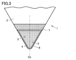
- FIG. 3 is a plan view of the cutting edge portion of FIG.
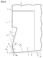
- FIG. 4 is a sectional view taken along the angle bisector CL of the nose R of FIG.
- FIG. 5 is a schematic cross-sectional view for explaining constituent blade edges formed during cutting.
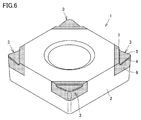
- FIG. 6 is a perspective view showing another example of the cutting tool according to the present embodiment.
- FIG. 7 is a perspective view showing another example of the cutting tool according to the present embodiment.
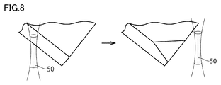
- FIG. 8 is a schematic diagram illustrating pulse laser processing.
- FIG. 9 is a graph showing the relationship between the wedge angle and the cutting length.
- FIG. 9 is a graph showing the relationship between the wedge angle and the cutting length.
- FIG. 10 is a graph showing the relationship between the sum of the rake angle and the chamfer angle and the cutting length.
- FIG. 11 is a graph showing the relationship between cutting speed and cutting length.
- FIG. 12 is a graph showing the relationship between the feed amount and the cutting length.
- a cubic boron nitride sintered body (cBN sintered body) having excellent high-temperature hardness is used for the cutting edge portion.
- Cutting tools (cBN sintered compact cutting tools) are known (for example, JP-A-2005-208807 (Patent Document 1) and International Publication No. 2014/181594 (Patent Document 2)).
- cBN sintered compact cutting tools are known (for example, JP-A-2005-208807 (Patent Document 1) and International Publication No. 2014/181594 (Patent Document 2)).
- a cBN sintered body cutting tool In order to improve the processing efficiency of difficult-to-cut materials using such a cBN sintered body cutting tool, it is being studied to perform processing at a cutting speed of 200 m/min or more. Further, in order to achieve higher cutting efficiency such as improving the cutting speed and lowering the cutting resistance, it has been considered to make the wedge angle sharp in the cBN sintered body cutting tool.
- the cBN sintered body has higher hardness than cemented carbide, it has low toughness. Therefore, if the wedge angle is sharpened in the cBN sintered body cutting tool, when the heat resistant alloy such as the nickel-base heat resistant alloy is cut, the boundary wear damage becomes large and the cutting edge tends to be damaged.
- an object of the present invention is to provide a cutting tool having excellent wear resistance in cutting of a nickel-base heat-resistant alloy, a method for manufacturing the cutting tool, and a method of processing a nickel-base heat-resistant alloy.
- a cutting tool includes A cubic boron nitride and a cutting tool including a cubic boron nitride sintered body consisting of a binder phase, A rake face, a flank face, and a chamfer face connecting the rake face and the flank face,
- the wedge angle formed by the rake face and the flank face is 60° or more and 70° or less
- the sum of the rake angle on the rake face and the chamfer angle on the chamfer face is 20° or more and 40° or less
- the chamfer length on the chamfer surface is 20 ⁇ m or more and 90 ⁇ m or less
- the cubic boron nitride has an average particle size of 0.5 ⁇ m or more and 2 ⁇ m or less
- the volume ratio of the cubic boron nitride is 45% by volume or more and 99% by volume or less
- the above cutting tool becomes a cutting tool having excellent wear resistance in the cutting of nickel-base heat-resistant alloy.
- the rake angle is 10° or more and 20° or less.
- the chamfer angle is 10° or more and 20° or less.
- the clearance angle on the clearance surface is 0° or more and 10° or less.
- the chamfer length is 20 ⁇ m or more and 50 ⁇ m or less.
- a method for manufacturing a cutting tool according to the present disclosure A method of manufacturing the cutting tool, including a step of forming the chamfer surface by pulse laser processing.
- a processing method of a nickel-base heat-resistant alloy according to the present disclosure A method for processing a nickel-base heat-resistant alloy using the above cutting tool, comprising a peripheral speed of 250 m/min or more and 400 m/min or less, a cutting amount of 1 mm or more and 2 mm or less, and a feed amount of 0.07 mm/rev or more and 0.1 mm/rev or less.
- the process includes wet processing under the conditions.
- this embodiment is not limited to this.
- the notation in the form of "AZ" means the upper and lower limits of the range (that is, A or more and Z or less), and when A has no unit, and only Z has a unit, A And the unit of Z are the same.
- a compound is represented by a chemical formula in which the composition ratio of constituent elements is not limited, such as “TiN”, the chemical formula is represented by any conventionally known composition ratio (element ratio). Shall be included.
- the above chemical formula includes not only the stoichiometric composition but also the non-stoichiometric composition.
- the chemical formula “TiN” includes not only the stoichiometric composition “Ti 1 N 1 ”, but also a non-stoichiometric composition such as “Ti 1 N 0.8 ”. This also applies to the description of compounds other than "TiN”.
- the wedge angle formed by the rake face and the flank face is 60 to 70°
- the sum of the rake angle on the rake face and the chamfer angle on the chamfer face is 20 to 40°
- the chamfer length on the chamfer surface is 20 to 90 ⁇ m
- the cubic boron nitride has an average particle size of 0.5 to 2 ⁇ m
- the volume ratio of the cubic boron nitride is 45 to 99% by volume based on the whole cubic boron nitride sintered body
- the bonded phase is at least one element selected from Group 4 elements, Group 5 elements and Group 6 elements of the periodic table of elements, and C (carbon), N (nitrogen
- FIG. 1 is a perspective view showing an example of a cutting tool according to this embodiment.
- FIG. 2 is an enlarged view of a cutting edge portion of the cutting tool of FIG.
- the cutting tool 1 according to the present embodiment has a rake face 5, a flank face 6, and a chamfer face 4 connecting the rake face 5 and the flank face 6. .
- the cutting tool 1 according to the present embodiment has the rake face 5, the flank face 6, and the chamfer face 4 in the cutting edge portion 3.
- the cutting tool 1 may be in the form of a throw-away tip that includes a cutting edge tip (portion hatched with fine dots in FIGS. 1 and 2) and a base metal 2 that holds the cutting edge tip, or the cutting edge tip. It may be its own shape. However, the shape of the cutting tool 1 is not limited to the shape described above.
- FIG. 3 is a plan view of the cutting edge portion of FIG.
- FIG. 4 is a sectional view taken along the angle bisector CL of the nose R of FIG.
- the cross-sectional view of FIG. 4 is a cross section cut perpendicular to a boundary line AA between the rake face 5 and the chamfer surface 4 and a boundary line BB between the flank face 6 and the chamfer surface 4 described later. It is a figure.
- the cross-sectional view of FIG. 4 can also be understood as a cross-sectional view cut along the angle bisector CL of the nose R and perpendicular to the rake face, the flank face and the chamfer face. .. In the cutting tools shown in FIGS.
- FIG. 4 has been described as a cross section of the nose R portion.
- the cutting tool according to the present disclosure is not limited to the embodiments shown in FIGS. 1 to 3, and if the cross section of a portion of the cutting tool involved in cutting has a shape as shown in FIG. It may have any configuration.
- the cutting tool has a wedge angle ⁇ w formed by the rake face and the flank (that is, an intersection angle at which a virtual plane including the rake face and a virtual plane including the flank intersect) of 60 to 70°. And more preferably 65 to 70°. By doing so, it becomes possible to suppress the cutting resistance.
- the sum of the wedge angle ⁇ w , the rake angle ⁇ R and the clearance angle ⁇ F described later is 90°.
- the sum of the rake angle on the rake face and the chamfer angle on the chamfer face is 20 to 40°, and more preferably 25 to 35°.
- the “rake angle” means an angle ⁇ R formed by the rake surface 5 and an imaginary plane A including the rake side main surface 7 as shown in FIG. 4.
- the virtual plane A can be grasped as a virtual plane orthogonal to the main surface of the work material, or can be grasped as a virtual plane perpendicular to the cutting direction. ..
- “Chamfer angle” means an angle ⁇ c formed by the chamfer surface 4 and the virtual plane A, as shown in FIG.
- the chamfer angle ⁇ c is preferably 10 to 20°, more preferably 15 to 20°.
- the constituent cutting edge described below tends to be stably generated.
- the chamfer length on the chamfer surface is 20 to 90 ⁇ m, preferably 20 to 50 ⁇ m.
- the “Chamfer length” means the distance L c between the boundary line AA between the rake surface 5 and the chamfer surface 4 and the boundary line BB between the flank surface 6 and the chamfer surface 4. To do.
- the chamfer width W c is preferably 20 to 90 ⁇ m.
- the chamfer width W c is a value obtained by (champfer length L c ) ⁇ cos (chamfer angle ⁇ c ).
- the chamfer width W c corresponds to the height when the chamfer surface 4 is projected on the virtual plane A (FIG. 4 ).
- the constituent cutting edge described below tends to be stably generated.
- the rake angle ⁇ R is preferably 10 to 20°, more preferably 15 to 20°.
- the clearance angle ⁇ F at the clearance surface is preferably 0 to 10°, more preferably 5 to 8°.
- the “clearance angle” means an angle ⁇ F formed by the clearance plane 6 and a virtual plane B orthogonal to the virtual plane A.
- the virtual plane B can be understood as a virtual plane including the main surface of the work material, or as a virtual plane parallel to the cutting direction.
- the shape of the cutting tool according to the present disclosure has been described above.
- the cutting tool has a wedge angle ⁇ w of 60 to 70°. Therefore, it is possible to cut the nickel-base heat-resistant alloy with a rake angle ⁇ R of 10 to 20°.
- the rake angle in the above range is common in cutting tools made of cemented carbide, high-speed steel or the like having high toughness.
- setting the rake angle to 10 to 20° has not been conventionally performed. The inventors believe that there are two reasons for this.
- the first reason is that although the cBN sintered body has high hardness, it has low toughness, so it is important to increase the fracture resistance of the cBN sintered body cutting tool for cutting nickel-base heat resistant alloys. It was thought that. From such a viewpoint, it has been considered preferable to design the rake angle of the cBN sintered body cutting tool to be less than 10°.
- the second reason is that when the rake angle is designed to be 10° or more, the cutting edge temperature decreases due to improved sharpness (that is, reduced cutting resistance).
- a method is adopted in which the temperature of the cutting edge is raised and the heat-resistant alloy, which is a work material, is softened by the generated cutting heat. It has been theoretically considered that even if the rake angle is designed to be 10° or more, the desired cutting edge temperature can be achieved by increasing the cutting speed.
- the cutting tool manufactured by the grinding process using the conventional diamond grindstone there is a microstructure destruction in the cutting edge as described later, so that the cutting edge becomes defective when the cutting speed is increased. It has not been put to practical use. From such a point of view, it has been considered that designing the rake angle to be 10° or more would make it difficult to cut the heat-resistant alloy and prevent the cutting edge from being damaged.
- the cutting tool according to the present disclosure has a chamfered surface formed by pulsed laser processing as described below, and thus microscopic tissue destruction occurring at the cutting edge is suppressed.
- the nickel-base heat-resistant alloy can be cut with high cutting efficiency (for example, high cutting speed). That is, in the cutting tool according to the present embodiment, the above-mentioned shape and the specific cBN sintered body described later are combined to form the constituent cutting edge steadily, so that the cutting resistance of the nickel-base heat-resistant alloy is reduced in wear resistance.
- a cutting tool with excellent fracture resistance can be provided.
- the cutting tool includes a cubic boron nitride sintered body including cubic boron nitride and a binder phase.
- the thermal conductivity of the cubic boron nitride sintered body (hereinafter sometimes referred to as “cBN sintered body”) is 20 to 70 W/m ⁇ K.
- the thermal conductivity for example, the thermal diffusivity of the cubic boron nitride sintered body obtained by measuring by the laser flash method, and the specific heat and density of the cubic boron nitride sintered body calculated by another method Can be calculated based on
- the average particle size of the cubic boron nitride (hereinafter sometimes referred to as “cBN”) is 0.5 to 2 ⁇ m. By doing so, a cBN sintered body having the above-described predetermined thermal conductivity can be obtained.
- the average grain size of cubic boron nitride is calculated as follows. First, an arbitrary position of the cutting tool according to the present embodiment is cut, and a sample including the cut surface is manufactured. Then, the cut surface of the cutting tool is observed using a SEM (scanning electron microscope) to obtain a backscattered electron image. The backscattered electron image obtained is analyzed using image analysis software, and the equivalent circle diameter of the corresponding region of cubic boron nitride is calculated. The average value is calculated from the calculated equivalent circle diameters. The obtained average value is defined as “average particle size of cubic boron nitride”.
- the volume ratio of the cubic boron nitride is 45 to 99% by volume, preferably 60 to 99% by volume, based on the whole of the cubic boron nitride sintered body.
- the volume ratio (volume %) of cubic boron nitride in the cubic boron nitride sintered body is obtained as follows. First, a sample including the cut surface of the above cutting tool is prepared and a backscattered electron image is obtained. Next, for the backscattered electron image, the region of cubic boron nitride is specified using the image analysis software described above. After that, the area ratio of the region of the cubic boron nitride is obtained, and this area ratio is treated as the volume ratio of the cubic boron nitride.
- the bonding phase includes at least one element selected from Group 4, Group 5 and Group 6 elements of the periodic table of elements and at least one element selected from C, N, B and O. .. More specifically, the binder phase is a nitride such as TiN, Si 3 N 4 or AlN, a carbide such as TiC or WC, a boride such as TiB 2 or AlB 2 or an oxide such as Al 2 O 3. Alternatively, it is made of TiCN, AlON, SiAlON, SiTiAlON, or other solid solution thereof, and particularly preferably contains any one of Al 2 O 3 , AlON, and SiAlON. Examples of the Group 4 element include Ti (titanium), Zr (zirconium), and Hf (hafnium).
- Examples of the Group 5 element include V (vanadium), Nb (niobium), and Ta (tantalum).
- Examples of the Group 6 element include Cr (chromium), Mo (molybdenum), and W (tungsten).
- TEM-EDX energy dispersive X-ray spectroscopy
- the cubic boron nitride sintered body may contain inevitable impurities as long as the effect of the present disclosure is not impaired.
- the unavoidable impurities are generic names of elements and compounds that may be contained in a trace amount in the raw material of the cubic boron nitride sintered body or in the production thereof.
- the content (volume %) of each element and compound contained as unavoidable impurities is 0 volume% or more and 5 volume% or less, respectively, and the sum of these (that is, the content of trace impurities) is 0 volume% or more and 5 volume% or less. Is. Therefore, inevitable impurities may or may not be contained in the cubic boron nitride sintered body.
- Examples of unavoidable impurities include Li, Mg, Ca, Sr, Ba, Be, Si, Ga, La, Zr, V, Nb, Ta, Hf, Fe and Cu.
- the cutting tool according to the present disclosure has been described.
- the cutting tool according to the present disclosure by combining the shape of the specific cutting tool described above and a specific cubic boron nitride sintered body, in the cutting process of the nickel-base heat-resistant alloy, wear resistance, chipping resistance It has been improved and a long life which has never been achieved is achieved.
- the detailed mechanism that exerts such an excellent effect is unknown, the present inventors believe that there are two factors described below.
- the first reason is that the wear of the rake face (crater wear) and the wear of the flank face (flank wear) at the cutting edge of the cutting tool progress in parallel, which balances the wear progress rates. Therefore, the apparent speed at which the width of crater wear and the width of flank wear increase is decreased.
- the abrasive wear of the cutting tool progresses at a high speed, but due to the progress of wear on the flank, the position of the cutting edge recedes and the flank wear width increases. At the same time, since the crater wear also progresses from the rake face, the flank wear width is apparently shortened.
- the width of crater wear on the rake face also increases with the progress of wear on the rake face, but the width of crater wear is apparently shortened due to the retreat of the cutting edge due to flank wear.
- the wear of the cutting edge progresses while the width of the crater wear that the cutting edge contacts with the chips and the width of the flank wear that contacts the machining surface are smaller than those of conventional tools, reducing the cutting edge friction heat and cutting resistance. It is thought that it is connected to.
- the second reason is that the cutting tool has a chamfered surface having a predetermined angle and length.
- a force that causes chips to flow in the component direction of the tool feed changes the outflow direction of chips. ..
- This phenomenon is caused by the flow of the chips flowing out from the cutting edge (between the chips and the tool rake surface), and the constituent cutting edge (a part of the work material welded on the chamfer surface) does not stick and is fluidized.
- FIG. 5 is a schematic cross-sectional view for explaining constituent blade edges formed during cutting.
- the constituent cutting edge normally undergoes a process in which a part of the work material adheres to the cutting edge of the cutting tool and grows and falls off.
- the constituent cutting edge 8 formed in the cutting tool 1 according to the present disclosure the generation and flow of the specific shape by a part of the work material are continued steadily and stably instead of the above-described process. Therefore, the constituent cutting edge 8 is provided between the chamfer surface 4 of the cutting tool 1 and the chips of the work material 9 and interposed therebetween to protect the cutting edge portion 3 of the cutting tool 1 (for example, , FIG. 5).
- the present inventors believe that such a phenomenon of stable generation of the cutting edge does not occur in a cemented carbide tool, a cermet tool, a ceramics tool, etc. having the same shape, and is a phenomenon peculiar to a cBN sintered body. ing.
- the cutting tool 1 may have a shape having cutting edge portions 3 at four corners as shown in FIG. Further, as shown in FIG. 7, a predetermined side of the cutting tool 1 may have a shape that constitutes the cutting edge portion 3.
- the cutting tool 1 is a throwaway tool including a cutting edge tip (portion hatched with fine dots in FIGS. 6 and 7) and a base metal 2 holding the cutting edge tip. It goes without saying that the shape of the tip may be the shape of the cutting edge tip itself.
- Manufacturing method of cutting tools The manufacturing method of the cutting tool according to the present disclosure, A method of manufacturing the cutting tool, including a step of forming the chamfer surface by pulse laser processing.
- the chamfer surface may be formed by pulse laser processing from the beginning, or after the chamfer surface is roughly processed by grinding with a diamond grindstone, the chamfer surface is processed by pulse laser processing. It may be formed by finishing the surface.
- FIG. 8 is a schematic diagram illustrating pulse laser processing.
- a region shown by a dot in FIG. 8 is a laser processing region 50, and for example, a plane of about 0.5 mm can be processed by uniaxial scanning.
- the device for generating the pulse laser is not particularly limited, but may be, for example, a device having the configuration disclosed in Japanese Patent Laid-Open No. 2016-159318 (Patent Document 3).
- Patent Document 3 Japanese Patent Laid-Open No. 2016-159318
- Examples of the commercially available device include Impact-3C manufactured by Xiton Co., Ltd.
- the conditions for the pulse laser processing are as follows, for example. Conditions for pulsed laser processing Laser wavelength: 355-1064nm Laser power: 2.5-10W Pulse width: 700fs-5ns Beam diameter: 20-40 ⁇ m Scan speed: 20-40mm/s Incident angle: 80-88.5° Cutting depth: 1-10 ⁇ m
- a cutting tool having a cBN sintered body as a cutting edge has a cutting edge portion formed by grinding with a diamond grindstone.
- the cBN sintered body is a brittle material with high hardness
- the cutting edge (cutting edge portion) generated by the conventional grinding process causes microstructural destruction around the ridge line of the cutting edge portion due to the stress applied by the grinding resistance. It was formed with it.
- a slight chipping occurs in the ridgeline portion of the cutting edge portion, and a microstructure defect accompanied by damage such as a minute crack occurs inside the cBN sintered body.
- the present inventors believe that these microstructure defects may cause damage to the cutting edge portion during cutting and cause unstable tool life. Especially, it has a great influence on a cutting tool having a small wedge angle and a large rake angle and a clearance angle designed. Therefore, in general, even if the rake angle is increased to manufacture a cutting tool with better sharpness, the strength of the cutting edge portion tends to decrease, and conversely the tool life tends to decrease. Therefore, the design value of the rake angle must be set to an upper limit (for example, less than 10°).
- pulse laser processing is used to form a chamfer surface, thereby realizing processing in which a microstructure defect is suppressed in the cBN sintered body at the cutting edge.
- the rake angle and the clearance angle of the cutting edge of the cutting tool can be designed to be large angles that cannot be conventionally assumed.
- the cutting tool manufactured by the above manufacturing method can achieve a long life under severe processing conditions such as high-speed processing of a nickel-base heat-resistant alloy.
- the processing method of the nickel-base heat-resistant alloy according to the present disclosure A method for processing a nickel-base heat-resistant alloy using the above cutting tool, which comprises a wet processing step under conditions of a peripheral speed of 250 to 400 m/min, a cutting amount of 1 to 2 mm, and a feed amount of 0.07 to 0.1 mm/rev. Including.
- the cutting edge portion is formed of a cBN sintered body having a low thermal conductivity as described above, and a specific wedge angle, chamfer angle, chamfer length, etc. are imparted.
- crater wear wear on the rake face
- flank wear wear on the flank face
- the life was improved as compared with the conventional cutting tool.
- the wear of the cutting edge portion progresses and the cutting resistance increases.
- the peripheral speed is 250 to 400 m/min (preferably 250 to 300 m/min)
- the cutting amount is 1 to 2 mm (preferably 1 to 1.7 mm)
- the feed amount is 0.07 to 0.1 mm/rev (preferably , 0.07 to 0.08 mm/rev)
- a cubic boron nitride and a cutting tool including a cubic boron nitride sintered body consisting of a binder phase, A rake face, a flank face, and a chamfer face connecting the rake face and the flank face,
- the wedge angle formed by the rake face and the flank face is 60 to 70°
- the sum of the rake angle on the rake face and the chamfer angle on the chamfer face is 20 to 40°
- the chamfer length on the chamfer surface is 20 to 90 ⁇ m
- the cubic boron nitride has an average particle size of 0.5 to 2 ⁇ m
- the cubic boron nitride has a volume ratio of 45 to 70% by volume based on the whole cubic boron nitride sintered body.
- the bonding phase includes at least one element selected from Group 4 elements, Group 5 elements and Group 6 elements of the periodic table of elements and at least one element selected from C, N, B and O.
- the cutting tool wherein the cubic boron nitride sintered body has a thermal conductivity of 20 to 70 W/m ⁇ K.
- Appendix 2 The cutting tool according to Appendix 1, wherein the rake angle is 10 to 20°.
- Appendix 3 The cutting tool according to Appendix 1 or Appendix 2, wherein the chamfer angle is 10 to 20°.
- Appendix 4 The cutting tool according to any one of appendixes 1 to 3, wherein the clearance angle on the flank is 0 to 10°. (Appendix 5) 5.
- Appendix 6 The method for manufacturing a cutting tool according to any one of appendixes 1 to 5, including a step of forming the chamfer surface by pulse laser processing.
- Appendix 7) A method for processing a nickel-base heat-resistant alloy using the cutting tool according to any one of appendixes 1 to 5, wherein a peripheral speed is 250 to 400 m/min, a cutting amount is 1 to 2 mm, and a feed amount is 0.07 to 0.1 mm.
- Experiment 1 ⁇ Preparation of cutting tools>> A cutting tool was produced using materials A to F described later and its cutting performance was evaluated.
- the cutting tool has the shape of a cutting edge tip shown by hatching of fine dots in FIG. Further, the rake angle, the clearance angle, the wedge angle, the chamfer angle and the chamfer length in the cutting tool were made to have variations, and each cutting tool was manufactured.
- the chamfer surface of each cutting tool was processed by pulse laser processing under the following conditions. Conditions for pulsed laser processing Laser wavelength: 355-1064nm Laser power: 2.5-10W Pulse width: 700fs-5ns Beam diameter: 20-40 ⁇ m Scan speed: 20-40mm/s Incident angle: 80-88.5° Cutting depth: 1-10 ⁇ m
- Table 1 shows the composition and thermal conductivity of cBN sintered bodies corresponding to materials A to D, and the average particle size of cBN.
- TiC ceramics material E, thermal conductivity 15 to 18 W/m ⁇ K
- WC material F, thermal conductivity 80 to 100 W/m ⁇ K
- ⁇ Cutting test ⁇ ⁇ Cutting test 1: roughing test> The cutting tool produced as described above is fixed to the base metal, the nickel-base heat-resistant alloy is roughly machined under the following cutting conditions, and the cutting distance until the flank wear of the cutting tool reaches 0.3 mm is measured. did. The longer the cutting distance, the more excellent the wear resistance can be evaluated as a cutting tool.
- Table 2 shows the rake angle, clearance angle, wedge angle, chamfer angle, and chamfer length of the cutting tools manufactured this time that had the longest cutting length in Cutting Test 1 (the cutting tools of Sample Nos. 1 to 10). Show. In addition, the sample No. Table 3 shows the cutting distance and the chip discharge efficiency of the cutting tools of 1 to 10.
- Sample No. for cutting test 1 The cutting tools 1 to 10 (Examples) had a cutting distance of 2500 m or more in rough machining of Inconel (registered trademark) 718, which is a nickel-based heat-resistant alloy, and a chip discharge efficiency of 9 to 36 cc/min.
- the cutting tools 1 to 5 and 7 to 10 were manufactured from the cBN sintered body of the material C.
- Sample No. The cutting tool of No. 6 was manufactured from the cBN sintered body of the material B.
- Experiment 2 ⁇ Examination of correlation between cutting tool shape and cutting length>> Correlation between the shape of the cutting tool (particularly, the wedge angle, and the sum of the rake angle and the chamfer angle) and the cutting length (cutting distance) using the cutting tool manufactured in ⁇ Preparation of cutting tool>> in Experiment 1. It was investigated. The cutting test at this time was performed under the same conditions as the cutting test 1 described above. The results are shown in FIGS. 9 and 10. A cutting tool having a cutting length of 2000 m or more was evaluated as a cutting tool having a long life. From the results of FIG. 9, it was suggested that the cutting tool having a wedge angle of 65 to 70° has a long cutting length and a particularly long life (a broken line region in FIG. 9). From the results of FIG. 10, it was suggested that the cutting tool having a sum of the rake angle and the chamfer angle of 25 to 35° has a long cutting length and a particularly long life (a broken line region in FIG. 10).
Abstract
立方晶窒化ホウ素と、結合相とからなる立方晶窒化ホウ素焼結体を含む、切削工具であって、すくい面と、逃げ面と、上記すくい面と上記逃げ面とを繋ぐチャンファー面とを有し、上記すくい面及び上記逃げ面によって形成されるくさび角が60°以上70°以下であり、上記すくい面におけるすくい角と前記チャンファー面におけるチャンファー角との和が20°以上40°以下であり、上記チャンファー面におけるチャンファー長が20μm以上90μm以下であり、上記立方晶窒化ホウ素の平均粒径が0.5μm以上2μm以下であり、上記立方晶窒化ホウ素の体積比率は、上記立方晶窒化ホウ素焼結体の全体を基準として、45体積%以上70体積%以下であり、上記結合相は、元素の周期表の第4族元素、第5族元素及び第6族元素のうちの少なくとも1つの元素と、炭素、窒素、ホウ素及び酸素のうちの少なくとも1つの元素とを含み、上記立方晶窒化ホウ素焼結体の熱伝導率が20W/m・K以上70W/m・K以下である、切削工具。
Description
本開示は切削工具、その製造方法、及びニッケル基耐熱合金の加工方法に関する。本出願は、2019年2月28日に出願した日本特許出願である特願2019-036062号に基づく優先権を主張する。当該日本特許出願に記載された全ての記載内容は、参照によって本明細書に援用される。
航空機ジェットエンジン、ロケットエンジン部品等は、高い耐熱性が求められている。航空機ジェットエンジン、ロケットエンジン部品等の材料としては、例えば、ニッケル基耐熱合金等が知られている。そして、切削加工においてニッケル基耐熱合金は、難削材料に位置付けられている。このような難削材料を切削するための切削工具としては、一般に超硬合金(炭化タングステン)からなる切削工具が使用されている。しかし、上記超硬合金からなる切削工具を用いた切削加工では、切削工具の損傷(例えば、刃先の摩耗、刃先の欠損等)を抑制する観点から、その切削速度は50m/min程度に制限されている。
本開示に係る切削工具は、
立方晶窒化ホウ素と、結合相とからなる立方晶窒化ホウ素焼結体を含む、切削工具であって、
すくい面と、逃げ面と、上記すくい面と上記逃げ面とを繋ぐチャンファー面とを有し、
上記すくい面及び上記逃げ面によって形成されるくさび角が60°以上70°以下であり、
上記すくい面におけるすくい角と前記チャンファー面におけるチャンファー角との和が20°以上40°以下であり、
上記チャンファー面におけるチャンファー長が20μm以上90μm以下であり、
上記立方晶窒化ホウ素の平均粒径が0.5μm以上2μm以下であり、
上記立方晶窒化ホウ素の体積比率は、上記立方晶窒化ホウ素焼結体の全体を基準として、45体積%以上99体積%以下であり、
上記結合相は、元素の周期表の第4族元素、第5族元素及び第6族元素のうちの少なくとも1つの元素と、炭素、窒素、ホウ素及び酸素のうちの少なくとも1つの元素とを含み、
上記立方晶窒化ホウ素焼結体の熱伝導率が20W/m・K以上70W/m・K以下である。
本開示に係る切削工具の製造方法は、
上記切削工具の製造方法であって、パルスレーザー加工によって、上記チャンファー面を形成する工程を含む。
上記切削工具の製造方法であって、パルスレーザー加工によって、上記チャンファー面を形成する工程を含む。
本開示に係るニッケル基耐熱合金の加工方法は、
上記切削工具を用いたニッケル基耐熱合金の加工方法であって、周速250m/分以上400m/分以下、切り込み量1mm以上2mm以下、送り量0.07mm/rev以上0.1mm/rev以下の条件において湿式加工する工程を含む。
上記切削工具を用いたニッケル基耐熱合金の加工方法であって、周速250m/分以上400m/分以下、切り込み量1mm以上2mm以下、送り量0.07mm/rev以上0.1mm/rev以下の条件において湿式加工する工程を含む。
[本開示が解決しようとする課題]
難削材料を切削するための切削工具としては、上述の超硬合金からなる切削工具の他にも、高温硬度に優れる立方晶窒化ホウ素焼結体(cBN焼結体)で刃先部を構成した切削工具(cBN焼結体切削工具)が知られている(例えば、特開2015-208807号公報(特許文献1)、国際公開第2014/181594号(特許文献2))。このようなcBN焼結体切削工具を用いて、難削材料の加工能率を向上させるために、200m/min以上の切削速度で加工を行うことが検討されている。また、切削速度を向上させる、切削抵抗を低くする等の、より高い切削効率を達成するためにcBN焼結体切削工具において、くさび角を鋭くすることが検討されている。
難削材料を切削するための切削工具としては、上述の超硬合金からなる切削工具の他にも、高温硬度に優れる立方晶窒化ホウ素焼結体(cBN焼結体)で刃先部を構成した切削工具(cBN焼結体切削工具)が知られている(例えば、特開2015-208807号公報(特許文献1)、国際公開第2014/181594号(特許文献2))。このようなcBN焼結体切削工具を用いて、難削材料の加工能率を向上させるために、200m/min以上の切削速度で加工を行うことが検討されている。また、切削速度を向上させる、切削抵抗を低くする等の、より高い切削効率を達成するためにcBN焼結体切削工具において、くさび角を鋭くすることが検討されている。
ところが、cBN焼結体は超硬合金に比べて高硬度である反面、靱性が低い。そのため、cBN焼結体切削工具においてくさび角を鋭くすると、ニッケル基耐熱合金等の耐熱合金を切削する場合、境界摩耗損傷が大きくなり、切れ刃に欠損が生じやすい傾向がある。
このような背景のもと、構成刃先で切削工具の切れ刃を保護する方法が提案されている。構成刃先を利用するための刃先部の形状について理論上の提案がなされているが、単にその形状を利用するだけでは実際に求められる切削性能(例えば、200m/min以上の切削速度で加工を行うこと等)を達成するまでには至っていない。
本開示は、上記事情に鑑みてなされたものであり、ニッケル基耐熱合金の切削加工において、耐摩耗性に優れる切削工具、その製造方法、及びニッケル基耐熱合金の加工方法を提供することを目的とする。
[本開示の効果]
本開示によれば、ニッケル基耐熱合金の切削加工において、耐摩耗性に優れる切削工具、その製造方法、及びニッケル基耐熱合金の加工方法を提供することが可能になる。
本開示によれば、ニッケル基耐熱合金の切削加工において、耐摩耗性に優れる切削工具、その製造方法、及びニッケル基耐熱合金の加工方法を提供することが可能になる。
[本開示の実施形態の説明]
最初に本開示の実施態様を列記して説明する。
[1]本開示に係る切削工具は、
立方晶窒化ホウ素と、結合相とからなる立方晶窒化ホウ素焼結体を含む、切削工具であって、
すくい面と、逃げ面と、上記すくい面と上記逃げ面とを繋ぐチャンファー面とを有し、
上記すくい面及び上記逃げ面によって形成されるくさび角が60°以上70°以下であり、
上記すくい面におけるすくい角と前記チャンファー面におけるチャンファー角との和が20°以上40°以下であり、
上記チャンファー面におけるチャンファー長が20μm以上90μm以下であり、
上記立方晶窒化ホウ素の平均粒径が0.5μm以上2μm以下であり、
上記立方晶窒化ホウ素の体積比率は、上記立方晶窒化ホウ素焼結体の全体を基準として、45体積%以上99体積%以下であり、
上記結合相は、元素の周期表の第4族元素、第5族元素及び第6族元素のうちの少なくとも1つの元素と、炭素、窒素、ホウ素及び酸素のうちの少なくとも1つの元素とを含み、
上記立方晶窒化ホウ素焼結体の熱伝導率が20W/m・K以上70W/m・K以下である。
上記切削工具は、上述のような構成を備えることによって、ニッケル基耐熱合金の切削加工において、耐摩耗性に優れる切削工具となる。
[2]上記すくい角は、10°以上20°以下である。このように規定することで、優れた耐摩耗性に加えて、速い切削速度の切削加工に適した切削工具となる。
[3]上記チャンファー角は、10°以上20°以下である。このように規定することで、このように規定することで、構成刃先が安定的に生成されるようになり、耐摩耗性に更に優れ、かつ耐欠損性に優れる切削工具となる。
[4]上記逃げ面における逃げ角は、0°以上10°以下である。このように規定することで、被削材の加工面に対する接触摩擦が抑制され、切削抵抗が低い切削工具となる。
[5]上記チャンファー長は20μm以上50μm以下である。このように規定することで、構成刃先が安定的に生成されるようになり、耐摩耗性に更に優れ、かつ耐欠損性に優れる切削工具となる。
[6]本開示に係る切削工具の製造方法は、
上記切削工具の製造方法であって、パルスレーザー加工によって、上記チャンファー面を形成する工程を含む。上記切削工具の製造方法は、上述のような構成を備えることによって、チャンファー面における微小な組織破壊の発生を抑制することが可能になる。その結果、ニッケル基耐熱合金の切削加工において、耐摩耗性に優れる切削工具を製造することが可能になる。
上記切削工具の製造方法であって、パルスレーザー加工によって、上記チャンファー面を形成する工程を含む。上記切削工具の製造方法は、上述のような構成を備えることによって、チャンファー面における微小な組織破壊の発生を抑制することが可能になる。その結果、ニッケル基耐熱合金の切削加工において、耐摩耗性に優れる切削工具を製造することが可能になる。
[7]本開示に係るニッケル基耐熱合金の加工方法は、
上記切削工具を用いたニッケル基耐熱合金の加工方法であって、周速250m/分以上400m/分以下、切り込み量1mm以上2mm以下、送り量0.07mm/rev以上0.1mm/rev以下の条件において湿式加工する工程を含む。上記ニッケル基耐熱合金の加工方法は、上述のような構成を備えることによって、高い切削効率でニッケル基耐熱合金を加工することが可能になる。
上記切削工具を用いたニッケル基耐熱合金の加工方法であって、周速250m/分以上400m/分以下、切り込み量1mm以上2mm以下、送り量0.07mm/rev以上0.1mm/rev以下の条件において湿式加工する工程を含む。上記ニッケル基耐熱合金の加工方法は、上述のような構成を備えることによって、高い切削効率でニッケル基耐熱合金を加工することが可能になる。
[本開示の実施形態の詳細]
以下、本開示の一実施形態(以下「本実施形態」と記す。)について説明する。ただし、本実施形態はこれに限定されるものではない。本明細書において「A~Z」という形式の表記は、範囲の上限下限(すなわちA以上Z以下)を意味し、Aにおいて単位の記載がなく、Zにおいてのみ単位が記載されている場合、Aの単位とZの単位とは同じである。さらに、本明細書において、例えば「TiN」等のように、構成元素の組成比が限定されていない化学式によって化合物が表された場合には、その化学式は従来公知のあらゆる組成比(元素比)を含むものとする。このとき上記化学式は、化学量論組成のみならず、非化学量論組成も含むものとする。例えば「TiN」の化学式には、化学量論組成「Ti1N1」のみならず、例えば「Ti1N0.8」のような非化学量論組成も含まれる。このことは、「TiN」以外の化合物の記載についても同様である。
以下、本開示の一実施形態(以下「本実施形態」と記す。)について説明する。ただし、本実施形態はこれに限定されるものではない。本明細書において「A~Z」という形式の表記は、範囲の上限下限(すなわちA以上Z以下)を意味し、Aにおいて単位の記載がなく、Zにおいてのみ単位が記載されている場合、Aの単位とZの単位とは同じである。さらに、本明細書において、例えば「TiN」等のように、構成元素の組成比が限定されていない化学式によって化合物が表された場合には、その化学式は従来公知のあらゆる組成比(元素比)を含むものとする。このとき上記化学式は、化学量論組成のみならず、非化学量論組成も含むものとする。例えば「TiN」の化学式には、化学量論組成「Ti1N1」のみならず、例えば「Ti1N0.8」のような非化学量論組成も含まれる。このことは、「TiN」以外の化合物の記載についても同様である。
≪切削工具≫
本実施形態に係る切削工具は、
立方晶窒化ホウ素と、結合相とからなる立方晶窒化ホウ素焼結体を含む、切削工具であって、
すくい面と、逃げ面と、上記すくい面と上記逃げ面とを繋ぐチャンファー面とを有し、
上記すくい面及び上記逃げ面によって形成されるくさび角が60~70°であり、
上記すくい面におけるすくい角と前記チャンファー面におけるチャンファー角との和が20~40°であり、
上記チャンファー面におけるチャンファー長が20~90μmであり、
上記立方晶窒化ホウ素の平均粒径が0.5~2μmであり、
上記立方晶窒化ホウ素の体積比率は、上記立方晶窒化ホウ素焼結体の全体を基準として、45~99体積%であり、
上記結合相は、元素の周期表の第4族元素、第5族元素及び第6族元素のうちの少なくとも1つの元素と、C(炭素)、N(窒素)、B(ホウ素)及びO(酸素)のうちの少なくとも1つの元素とを含み、
上記立方晶窒化ホウ素焼結体の熱伝導率が20~70W/m・Kである。
<切削削工具の形状>
図1は、本実施形態に係る切削工具の一例を示す斜視図である。図2は、図1の切削工具の刃先部の拡大図である。図1及び図2に示されるように、本実施形態に係る切削工具1は、すくい面5と、逃げ面6と、上記すくい面5と上記逃げ面6とを繋ぐチャンファー面4とを有する。
本実施形態にかかる切削工具1は、刃先部3において、すくい面5と、逃げ面6と、チャンファー面4とを有すると把握することもできる。上記切削工具1は、刃先チップ(図1及び図2において微細ドットでハッチングした部分)と上記刃先チップを保持する台金2とからなるスローアウェーチップの形状であってもよいし、上記刃先チップそのものの形状であってもよい。ただし、上記切削工具1の形状は、上述した形状に限られない。
図3は、図2の刃先部の平面図である。図4は、図3のノーズRの角二等分線CLに沿った断面図である。ここで、図4の断面図は、後述するすくい面5とチャンファー面4との境界線AA及び逃げ面6とチャンファー面4との境界線BBに対して垂直となるように切断した断面図である。また、図4の断面図は、ノーズRの角二等分線CLを通り、かつ、すくい面、逃げ面及びチャンファー面に対して垂直となるように切断した断面図と把握することもできる。
図1~図3に示す切削工具は、すくい面と逃げ面とが交差する稜のうちノーズRに対応する部分(以下、「ノーズR部」と表記する場合がある。)が切削に関与する部分(すなわち、切削時に被削材と実際に接触する部分)である。そのため、図4をノーズR部の断面として説明した。しかしながら、本開示に係る切削工具は図1~図3に示される態様に限定されず、切削工具のうち、切削に関与する部分の断面が図4に示されるような態様を有する形状であればどのような構成をとってもよい。例えば、すくい面と逃げ面とが交差する稜のうちストレート部分が切削に関与する部分である切削工具の場合(例えば、図7で示される切削工具の場合)には、当該ストレート部分の断面が図4に示されるような態様をとることにより本開示の効果を奏する。また、上記稜のうちストレート部分およびノーズR部の両方が切削に関与する部分である切削工具の場合には、当該ストレート部分および当該ノーズR部の両方が、図4で示されるような態様をとることにより本開示の効果を奏する。以下図4に基づいて説明する。
図1~図3に示す切削工具は、すくい面と逃げ面とが交差する稜のうちノーズRに対応する部分(以下、「ノーズR部」と表記する場合がある。)が切削に関与する部分(すなわち、切削時に被削材と実際に接触する部分)である。そのため、図4をノーズR部の断面として説明した。しかしながら、本開示に係る切削工具は図1~図3に示される態様に限定されず、切削工具のうち、切削に関与する部分の断面が図4に示されるような態様を有する形状であればどのような構成をとってもよい。例えば、すくい面と逃げ面とが交差する稜のうちストレート部分が切削に関与する部分である切削工具の場合(例えば、図7で示される切削工具の場合)には、当該ストレート部分の断面が図4に示されるような態様をとることにより本開示の効果を奏する。また、上記稜のうちストレート部分およびノーズR部の両方が切削に関与する部分である切削工具の場合には、当該ストレート部分および当該ノーズR部の両方が、図4で示されるような態様をとることにより本開示の効果を奏する。以下図4に基づいて説明する。
上記切削工具は、上記すくい面及び上記逃げ面によって形成されるくさび角θw(すなわち、上記すくい面を含む仮想平面と上記逃げ面を含む仮想平面とが交差する交差角)が60~70°であり、65~70°であることがより好ましい。このようにすることによって、切削抵抗を抑制することが可能になる。
なお、上記くさび角θw、後述するすくい角θR及び逃げ角θFの和は、90°である。
なお、上記くさび角θw、後述するすくい角θR及び逃げ角θFの和は、90°である。
上記切削工具は、上記すくい面におけるすくい角と前記チャンファー面におけるチャンファー角との和が20~40°であり、25~35°であることがより好ましい。
ここで「すくい角」とは、図4に示されるように、上記すくい面5と、すくい側主面7を含む仮想平面Aとによって形成される角度θRを意味する。本実施形態の一側面において、上記仮想平面Aは、被削材の主面に対して直交する仮想平面と把握することもできるし、切削方向に対して垂直な仮想平面と把握することもできる。
「チャンファー角」とは、図4に示されるように、上記チャンファー面4と上記仮想平面Aとによって形成される角度θcを意味する。
本実施形態において、上記チャンファー角θcは、10~20°であることが好ましく、15~20°であることがより好ましい。チャンファー角θcが上述の範囲をとることによって、後述する構成刃先が安定的に生成される傾向がある。
上記切削工具は、上記チャンファー面におけるチャンファー長が20~90μmであり、20~50μmであることが好ましい。ここで、本明細書において「チャンファー長」とは、すくい面5とチャンファー面4との境界線AAと、逃げ面6とチャンファー面4との境界線BBとの距離Lcを意味する。
本実施形態の一側面において、チャンファー幅Wcは、20~90μmであることが好ましい。ここで、チャンファー幅Wcは、(チャンファー長Lc)×cos(チャンファー角θc)で求められる値である。上記チャンファー幅Wcは、チャンファー面4を仮想平面Aに投影したときの高さに相当する(図4)。チャンファー幅Wcが上述の範囲をとることによって、後述する構成刃先が安定的に生成される傾向がある。
本実施形態において、上記すくい角θRは、10~20°であることが好ましく、15~20°であることがより好ましい。
本実施形態において、上記逃げ面における逃げ角θFは、0~10°であることが好ましく、5~8°であることがより好ましい。ここで「逃げ角」とは、上記逃げ面6と、上記仮想平面Aに対して直交する仮想平面Bとによって形成される角度θFを意味する。本実施形態の一側面において、上記仮想平面Bは、被削材の主面を含む仮想平面と把握することもできるし、切削方向に対して平行な仮想平面と把握することもできる。
以上、本開示に係る切削工具の形状について説明した。上記切削工具は、くさび角θwが60~70°である。そのため、10~20°のすくい角θRで、ニッケル基耐熱合金を切削加工することが可能である。上述のような範囲のすくい角は、靱性の高い超硬合金、高速度鋼等からなる切削工具では一般的である。しかしながら、cBN焼結体切削工具において、すくい角を10~20°に設定することは従来行われていなかった。これには2つの理由があると本発明者らは考えている。
1つめの理由は、cBN焼結体は高硬度である反面、靱性が低いために、cBN焼結体切削工具では、ニッケル基耐熱合金を切削加工する用途では、耐欠損性を高めることが重要と考えられていたことにある。このような観点から、cBN焼結体切削工具では、すくい角を10°未満に設計するのが好ましいと考えられていた。
2つめの理由は、すくい角を10°以上に設計すると切れ味の向上(すなわち、切削抵抗の低減)による刃先温度の低下が起こることに起因する。通常、耐熱合金を切削加工する場合、刃先温度を上昇させて、発生した切削熱で被削材である耐熱合金を軟化させながら加工する方法が採られている。すくい角を10°以上に設計しても、切削速度を上げれば所望の刃先温度にすることは理論上考えられていた。しかし、従来から行われているダイヤモンド砥石を用いた研削加工で製造された切削工具では、後述するように微小な組織破壊が切れ刃に存在するため、切削速度を上げると切れ刃の欠損が起こり実用化には至っていなかった。このような観点から、すくい角を10°以上に設計することは、耐熱合金の切削加工を困難にすると考えられ、また切れ刃の欠損防止も図れなくなるものと考えられていた。
上述したような2つの理由から、耐熱合金を切削加工する用途のcBN焼結体切削工具に、10°以上のすくい角を付与することで切削工具の寿命を向上させうる知見は従来なかった。
本開示に係る切削工具は、後述するようにパルスレーザー加工によってチャンファー面を形成しているため、切れ刃に発生する微小な組織破壊が抑制されている。その結果、上記切削工具は、10°以上のすくい角を有していても、高い切削効率(例えば、速い切削速度等)でニッケル基耐熱合金を切削加工することができる。すなわち、本実施形態に係る切削工具は、上述した形状と、後述する特定のcBN焼結体とが相まって構成刃先が定常的に形成されるため、ニッケル基耐熱合金の切削加工において、耐摩耗性、耐欠損性に優れる切削工具とすることができる。
<立方晶窒化ホウ素焼結体>
上記切削工具は、立方晶窒化ホウ素と、結合相とからなる立方晶窒化ホウ素焼結体を含む。
上記切削工具は、立方晶窒化ホウ素と、結合相とからなる立方晶窒化ホウ素焼結体を含む。
上記立方晶窒化ホウ素焼結体(以下、「cBN焼結体」と表記する場合がある。)の熱伝導率は、20~70W/m・Kである。上記熱伝導率は、例えば、レーザーフラッシュ法により測定して得られた立方晶窒化ホウ素焼結体の熱拡散率と、別の方法で算出された立方晶窒化ホウ素焼結体の比熱および密度とに基づいて算出することができる。
上記立方晶窒化ホウ素(以下、「cBN」と表記する場合がある。)の平均粒径は、0.5~2μmである。このようにすることによって、上述した所定の熱伝導率を有するcBN焼結体とすることができる。
立方晶窒化ホウ素の平均粒径は、次のようにして求められる。まず本実施形態に係る切削工具の任意の位置を切断し、その切断面を含む試料を作製する。次いで、切削工具の切断面をSEM(走査型電子顕微鏡)を用いて観察し、反射電子像を得る。得られた反射電子像を画像解析ソフトを用いて解析し、立方晶窒化ホウ素の対応する領域の円相当径を算出する。算出した円相当径から平均値を求める。求められた平均値を「立方晶窒化ホウ素の平均粒径」とする。
上記立方晶窒化ホウ素の体積比率は、上記立方晶窒化ホウ素焼結体の全体を基準として、45~99体積%であり、60~99体積%であることが好ましい。
立方晶窒化ホウ素焼結体中の立方晶窒化ホウ素の体積比率(体積%)は、次のようにして求められる。まず上述の切削工具の切断面を含む試料を作製し、反射電子像を得る。次いで、この反射電子像に対して上述した画像解析ソフトを用いて立方晶窒化ホウ素の領域を特定する。その後、上記立方晶窒化ホウ素の領域の面積比率を求め、この面積比率を上記立方晶窒化ホウ素の体積比率として取り扱う。
上記結合相は、元素の周期表の第4族元素、第5族元素及び第6族元素のうちの少なくとも1つの元素と、C、N、B及びOのうちの少なくとも1つの元素とを含む。より具体的には、上記結合相は、TiN、Si3N4、AlNなどの窒化物、TiC、WCなどの炭化物、TiB2、AlB2などのホウ化物、Al2O3などの酸化物など、或いは、TiCN、AlON、SiAlON、SiTiAlONなどこれらの固溶体からなり、特にAl2O3、やAlON、SiAlONのいずれか一つを含むことが好ましい。上記第4族元素としては、例えばTi(チタン)、Zr(ジルコニウム)、Hf(ハフニウム)が挙げられる。第5族元素としては、例えばV(バナジウム)、Nb(ニオブ)、Ta(タンタル)が挙げられる。上記第6族元素としては、例えばCr(クロム)、Mo(モリブデン)、W(タングステン)が挙げられる。上記結合相に含まれる各成分は、上述の切削工具の切断面を含む試料をTEM(透過型電子顕微鏡)に付帯のエネルギー分散型X線分光法(TEM-EDX)で、結合相に対応する領域を分析することによって求めることが可能である。このときの観察倍率は、例えば、10000倍である。
<不可避不純物>
上記立方晶窒化ホウ素焼結体は、本開示が奏する効果を損なわない範囲において、不可避不純物を含んでいてもよい。不可避不純物とは、立方晶窒化ホウ素焼結体の原料中に、又はその製造上において微量に含まれる可能性がある元素および化合物の総称をいう。不可避不純物として含まれる各元素及び化合物の含有量(体積%)は、それぞれ0体積%以上5体積%以下であり、これらの総和(すなわち微量不純物の含有量)は0体積%以上5体積%以下である。したがって、不可避不純物は、上記立方晶窒化ホウ素焼結体に含まれていてもよく、含まれていなくてもよい。不可避不純物としては、例えば、Li、Mg、Ca、Sr、Ba、Be、Si、Ga、La、Zr、V、Nb、Ta、Hf、Fe、Cuなどが挙げられる。
上記立方晶窒化ホウ素焼結体は、本開示が奏する効果を損なわない範囲において、不可避不純物を含んでいてもよい。不可避不純物とは、立方晶窒化ホウ素焼結体の原料中に、又はその製造上において微量に含まれる可能性がある元素および化合物の総称をいう。不可避不純物として含まれる各元素及び化合物の含有量(体積%)は、それぞれ0体積%以上5体積%以下であり、これらの総和(すなわち微量不純物の含有量)は0体積%以上5体積%以下である。したがって、不可避不純物は、上記立方晶窒化ホウ素焼結体に含まれていてもよく、含まれていなくてもよい。不可避不純物としては、例えば、Li、Mg、Ca、Sr、Ba、Be、Si、Ga、La、Zr、V、Nb、Ta、Hf、Fe、Cuなどが挙げられる。
以上、本開示に係る切削工具を説明した。本開示に係る切削工具は、上述の特定の切削工具の形状と、特定の立方晶窒化ホウ素焼結体とを組み合わせることによって、ニッケル基耐熱合金の切削加工において、耐摩耗性、耐欠損性が向上し、従来にない長い寿命が達成されたものである。このような優れた効果を奏する詳細なメカニズムは不明であるが、以下に述べる2つの要因があると本発明者らは考えている。
1つ目の理由としては、切削工具の刃先部におけるすくい面の摩耗(クレーター摩耗)と逃げ面の摩耗(フランク摩耗)との両方が併行して進むことで、それらの摩耗進行速度がバランスするために、クレーター摩耗の幅及びフランク摩耗の幅が増大する見かけ上の速度が低下することが挙げられる。
つまり難削材料であるニッケル基耐熱合金の切削加工では、切削工具のアブレイシブ摩耗は高速に進んでいくが、逃げ面における摩耗の進展により刃先の位置が後退してフランク摩耗の幅が増加する。それと同時に、すくい面からもクレーター摩耗が進むため、見かけ上フランク摩耗の幅が短くなる。
一方、すくい面のクレーター摩耗の幅もすくい面における摩耗の進展とともに大きくなるが、フランク摩耗による刃先の後退によりクレーター摩耗の幅は見かけ上短くなっていく。この結果、刃先部が切り屑と接触するクレーター摩耗の幅、および加工面と接触するフランク摩耗の幅が従来工具よりも小さいまま刃先の摩耗が進行し、刃先摩擦熱の低減、切削抵抗の低減につながっていることが考えられる。
2つ目の理由は、所定の角度及び長さを有するチャンファー面を上記切削工具に設けたことに起因する。このような切削工具を用いてニッケル基耐熱合金を切削した場合の切削抵抗を分析した結果、工具送り分力方向に切り屑を流す力が発生し、切り屑の流出方向が変わることが分かった。この現象は、切れ刃から流出する切り屑の流れの下(切り屑と工具すくい面の間)より構成刃先(チャンファー面において溶着した被削材の一部)が固着することなく流動的に横方向に流れているために観察されたと本発明者らは考えている。図5は、切削加工時に形成される構成刃先を説明する模式断面図である。構成刃先は、通常、切削工具の刃先部に被削材の一部が固着し、成長脱落するようなプロセスを経ることが知られている。しかし、本開示に係る切削工具1において形成される構成刃先8では、上述のようなプロセスではなく、定常安定的に被削材の一部による特定形状の生成と流動を続けている。そのため、上記構成刃先8は、切削工具1のチャンファー面4と被削材9の切り屑との間にあって両者に介在することによって切削工具1の刃先部3を保護する役割をはたしている(例えば、図5)と本発明者らは考えている。
このような構成刃先の流動現象は古くから提唱されてきた現象ではあるが、ニッケル基耐熱合金等の耐熱合金の切削加工において確認されたことがこれまでにはなかった。今回、上述の特定の切削工具の形状と、特定の立方晶窒化ホウ素焼結体とを組み合わせることによって、安定的に構成刃先を発生させる切削現象を本発明者らは初めて見出した。
このような構成刃先の安定的な発生という現象は、同形状の超硬工具、サーメット工具、セラミックス工具などでは発生することがなく、cBN焼結体特有の現象であると本発明者らは考えている。
以上、本開示に係る切削工具を説明したが、本開示に係る切削工具は上述した実施形態に限られない。例えば、上記切削工具1は、図6に示すように四隅において、刃先部3を有する形状であってもよい。また、図7に示すように切削工具1における所定の一辺において、刃先部3を構成する形状を有していてもよい。なお、図6及び図7いずれの場合においても、上記切削工具1は、刃先チップ(図6及び図7において微細ドットでハッチングした部分)と上記刃先チップを保持する台金2とからなるスローアウェーチップの形状であってもよいし、上記刃先チップそのものの形状であってもよいことは言うまでもない。
≪切削工具の製造方法≫
本開示に係る切削工具の製造方法は、
上記切削工具の製造方法であって、パルスレーザー加工によって、上記チャンファー面を形成する工程を含む。
本開示に係る切削工具の製造方法は、
上記切削工具の製造方法であって、パルスレーザー加工によって、上記チャンファー面を形成する工程を含む。
上記チャンファー面を形成する工程は、はじめからパルスレーザー加工によってチャンファー面を形成してもよいし、ダイヤモンド砥石による研削などでチャンファー面の粗加工を行った後に、パルスレーザー加工によってチャンファー面を仕上げ加工することで形成してもよい。
図8は、パルスレーザー加工を説明する模式図である。図8におけるドットで示されている領域がレーザー加工領域50で、例えば、0.5mm程度の平面を一軸走査で加工可能である。
パルスレーザーを発生させる装置としては特に制限はないが、例えば、特開2016-159318号公報(特許文献3)に開示されている構成を備える装置であってもよい。市販されている装置としては例えば、Xiton社製、商品名Impact-3Cが挙げられる。また、パルスレーザー加工の条件は、例えば以下のものが挙げられる。
パルスレーザー加工の条件
レーザー波長 :355~1064nm
レーザー出力 :2.5~10W
パルス幅 :700fs~5ns
ビーム径 :20~40μm
スキャン速度 :20~40mm/s
入射角 :80~88.5°
切削深度 :1~10μm
パルスレーザー加工の条件
レーザー波長 :355~1064nm
レーザー出力 :2.5~10W
パルス幅 :700fs~5ns
ビーム径 :20~40μm
スキャン速度 :20~40mm/s
入射角 :80~88.5°
切削深度 :1~10μm
ここで、本開示に係る切削工具の製造方法の効果について説明する。従来、cBN焼結体を切れ刃に持つ切削工具は、ダイヤモンド砥石による研削加工により、刃先部が生成される。しかしながら、cBN焼結体は高硬度な脆性材料であるため、従来の研削加工によって生成される切れ刃(刃先部)は、研削抵抗による応力付加によって刃先部の稜線の周辺にミクロな組織破壊を伴って形成されていた。この結果、刃先部の稜線部分には微少なチッピングが発生し、またcBN焼結体の内部において微少な亀裂などの損傷を伴った組織欠陥が発生していることも推測されている。これらの微少な組織欠陥が切削加工時における刃先部の損傷の要因となることがあり、工具寿命が不安定になる原因になっていると本発明者らは考えている。特にすくい角、逃げ角を大きく設計した、くさび角の小さい切削工具においてはその影響が大きい。このため一般的にはすくい角の角度を大きくしてより切れ味の良い切削工具を製造したとしても刃先部の強度の低下により逆に工具寿命の低下を招く傾向がある。そのためすくい角の角度の設計値は上限(たとえば10°未満等)を設けざるを得なかった。
本開示による切削工具の製造方法では、チャンファー面の形成にパルスレーザー加工を用いることによって、刃先部におけるcBN焼結体にミクロな組織欠陥を抑制した加工を実現した。本開示による切削工具の製造方法を採用することで、切削工具の刃先部のすくい角及び逃げ角を、従来では想定できない大きい角度に設計できる。上記製造方法で製造された切削工具は、ニッケル基耐熱合金の高速加工等の過酷な加工条件下において、長寿命を達成することが可能である。
≪切削工具を用いたニッケル基耐熱合金の加工方法≫
本開示に係るニッケル基耐熱合金の加工方法は、
上記切削工具を用いたニッケル基耐熱合金の加工方法であって、周速250~400m/分、切り込み量1~2mm、送り量0.07~0.1mm/revの条件において湿式加工する工程を含む。
本開示に係るニッケル基耐熱合金の加工方法は、
上記切削工具を用いたニッケル基耐熱合金の加工方法であって、周速250~400m/分、切り込み量1~2mm、送り量0.07~0.1mm/revの条件において湿式加工する工程を含む。
本開示に係る切削工具は、刃先部を上述したように熱伝導率の低いcBN焼結体で形成し、また、特定のくさび角、チャンファー角、チャンファー長等を付与している。このような切削工具は、従来の刃先強化処理を施した耐熱合金用の切削工具に比べて、クレーター摩耗(すくい面における摩耗)及びフランク摩耗(逃げ面における摩耗)が抑制される。その結果、従来の切削工具よりも寿命が向上することが確認された。一般には切削時間が長くなるのに伴って、刃先部の摩耗が進展し切削抵抗が大きくなる。これに対して本開示に係る切削工具では切削抵抗の増大が小さく、低い抵抗値を維持したまま加工が継続できる。そのため、周速250~400m/分(好ましくは、250~300m/分)、切り込み量1~2mm(好ましくは、1~1.7mm)、送り量0.07~0.1mm/rev(好ましくは、0.07~0.08mm/rev)の条件において湿式加工することによって、高い切り屑排出能率Q(例えば、30cc/分以上)でニッケル基耐熱合金の加工が可能である。
以上の説明は、以下に付記する特徴を含む。
(付記1)
立方晶窒化ホウ素と、結合相とからなる立方晶窒化ホウ素焼結体を含む、切削工具であって、
すくい面と、逃げ面と、前記すくい面と前記逃げ面とを繋ぐチャンファー面とを有し、
前記すくい面及び前記逃げ面によって形成されるくさび角が60~70°であり、
前記すくい面におけるすくい角と前記チャンファー面におけるチャンファー角との和が20~40°であり、
前記チャンファー面におけるチャンファー長が20~90μmであり、
前記立方晶窒化ホウ素は、その平均粒径が0.5~2μmであり、
前記立方晶窒化ホウ素は、前記立方晶窒化ホウ素焼結体の全体を基準として、その体積比率が45~70体積%であり、
前記結合相は、元素の周期表の第4族元素、第5族元素及び第6族元素のうちの少なくとも1つの元素と、C、N、B及びOのうちの少なくとも1つの元素とを含み、
前記立方晶窒化ホウ素焼結体は、その熱伝導率が20~70W/m・Kである、切削工具。
(付記2)
前記すくい角は、10~20°である、付記1に記載の切削工具。
(付記3)
前記チャンファー角は、10~20°である、付記1又は付記2に記載の切削工具。
(付記4)
前記逃げ面における逃げ角は、0~10°である、付記1から付記3のいずれかに記載の切削工具。
(付記5)
前記チャンファー長は20~50μmである、付記1から付記4のいずれかに記載の切削工具。
(付記6)
付記1から付記5のいずれかに記載の切削工具の製造方法であって、パルスレーザー加工によって、前記チャンファー面を形成する工程を含む、切削工具の製造方法。
(付記7)
付記1から付記5のいずれかに記載の切削工具を用いたニッケル基耐熱合金の加工方法であって、周速250~400m/分、切り込み量1~2mm、送り量0.07~0.1mm/revの条件において湿式加工する工程を含む、ニッケル基耐熱合金の加工方法。
以下、実施例を挙げて本発明を詳細に説明するが、本発明はこれらに限定されるものではない。
実験1
≪切削工具の作製≫
後述する材料A~Fを用いて切削工具を作製して、その切削性能を評価した。上記切削工具は、図1において微細ドットのハッチングで示されている刃先チップの形状である。また、切削工具におけるすくい角、逃げ角、くさび角、チャンファー角及びチャンファー長は、それぞれバリエーションを持たせて各切削工具を作製した。ここで、各切削工具のチャンファー面は、以下の条件でパルスレーザー加工することで行った。
パルスレーザー加工の条件
レーザー波長 :355~1064nm
レーザー出力 :2.5~10W
パルス幅 :700fs~5ns
ビーム径 :20~40μm
スキャン速度 :20~40mm/s
入射角 :80~88.5°
切削深度 :1~10μm
表1に材料A~Dに対応するcBN焼結体の組成及び熱伝導率、cBNの平均粒径を示す。また、その他の焼結体として、TiCセラミックス(材料E、熱伝導率15~18W/m・K)及びWC(材料F、熱伝導率80~100W/m・K)を用いた。

≪切削試験≫
<切削試験1:粗加工試験>
上述のようにして作製した切削工具を台金に固定して、以下の切削条件によりニッケル基耐熱合金の粗加工を行い、切削工具の逃げ面摩耗が0.3mmに達するまでの切削距離を測定した。切削距離が長いほど耐摩耗性に優れる切削工具として評価することができる。今回製造した切削工具の中でも切削試験1において切削長が長かった切削工具(試料No.1~10の切削工具)のすくい角、逃げ角、くさび角、チャンファー角及びチャンファー長を表2に示す。また、試料No.1~10の切削工具の切削距離及び切り屑排出能率を表3に示す。
切削条件
被削材 :インコネル(登録商標)718(丸棒)
切削速度(周速):300m/min
送り量 :0.07mm/rev
切込み量(ap):1.73mm、wet


切削試験1について、試料No.1~10の切削工具(実施例)は、ニッケル基耐熱合金であるインコネル(登録商標)718の粗加工における切削距離が2500m以上であり、切り屑排出能率が9~36cc/分であった。また、試料No.1~5及び7~10の切削工具は、材料CのcBN焼結体から製造されたものであった。試料No.6の切削工具は、材料BのcBN焼結体から製造されたものであった。
<刃先の摩耗形態の観察>
切削加工後に試料No.1~10の切削工具(実施例)の刃先を観察したところ、クレーター摩耗及びフランク摩耗がバランスして(すなわち、均一に進行し)、見かけ上の摩耗幅の増加が抑制されていることが分かった。このような摩耗形態によって、従来以上に切削工具の寿命が延びると本発明者らは考えている。
切削加工後に試料No.1~10の切削工具(実施例)の刃先を観察したところ、クレーター摩耗及びフランク摩耗がバランスして(すなわち、均一に進行し)、見かけ上の摩耗幅の増加が抑制されていることが分かった。このような摩耗形態によって、従来以上に切削工具の寿命が延びると本発明者らは考えている。
<構成刃先流動現象の観察>
切削試験1における切削加工の様子を高速カメラで観察したところ、構成刃先の流動現象が確認された。上記構成刃先は、刃先部の摩耗及び溶着を抑制する。そのため、ニッケル基耐熱合金の乾式切削をした場合でも、光沢があり、かつツールマークが明瞭な加工面が得られたと本発明者らは考えている。
切削試験1における切削加工の様子を高速カメラで観察したところ、構成刃先の流動現象が確認された。上記構成刃先は、刃先部の摩耗及び溶着を抑制する。そのため、ニッケル基耐熱合金の乾式切削をした場合でも、光沢があり、かつツールマークが明瞭な加工面が得られたと本発明者らは考えている。
<チャンファー面に関する考察>
実施例である試料No.1~10の切削工具では、チャンファー長が20~62μmである。このチャンファー長は短い程、切削抵抗が小さく(すなわち、切れ味が良く)、摩耗の増加量は小さく抑えられることが分かった。このような微小なチャンファー長を持つチャンファー面を均一に形成する加工は、従来からの研削加工では困難であり、パルスレーザー加工によってはじめて可能になったと本発明者らは考えている。
実施例である試料No.1~10の切削工具では、チャンファー長が20~62μmである。このチャンファー長は短い程、切削抵抗が小さく(すなわち、切れ味が良く)、摩耗の増加量は小さく抑えられることが分かった。このような微小なチャンファー長を持つチャンファー面を均一に形成する加工は、従来からの研削加工では困難であり、パルスレーザー加工によってはじめて可能になったと本発明者らは考えている。
実験2
≪切削工具の形状と切削長との相関関係の検討≫
実験1の≪切削工具の作製≫において作製した切削工具を用いて、切削工具の形状(特に、くさび角、及びすくい角とチャンファー角との和)と切削長(切削距離)との相関関係を検討した。このときの切削試験は、上述の切削試験1と同様の条件にて行った。その結果を図9及び図10に示す。切削長が2000m以上である切削工具を、寿命が長い切削工具と評価した。
図9の結果から、くさび角が65~70°である切削工具は、切削長が長く特に寿命が長いことが示唆された(図9の破線の領域)。また、図10の結果から、すくい角とチャンファー角との和が25~35°である切削工具は、切削長が長く特に寿命が長いことが示唆された(図10の破線の領域)。
≪切削条件と切削長との相関関係の検討≫
実験1の≪切削工具の作製≫において作製した切削工具を用いて、切削試験における切削条件(特に、切削速度、及び送り量)と切削長との相関関係を検討した。このときの切削試験は、上述の切削試験1の条件を元に、切削速度又は送り量を変化させて行った。その結果を図11及び図12に示す。切削長が2000m以上である切削条件を、良好な切削条件と評価した。
図11の結果から、切削速度が200~450m/min(好ましくは250~300m/min)である切削試験のときに切削長が長く、良好であることが示唆された(図11の破線の領域)。また、図12の結果から、送り量が0.040~0.140mm/rev(好ましくは0.07~0.08mm/rev)である切削試験のときに切削長が長く、良好であることが示唆された(図12の破線の領域)。
以上のように本発明の実施形態及び実施例について説明を行なったが、上述の各実施形態及び各実施例の構成を適宜組み合わせることも当初から予定している。
今回開示された実施の形態及び実施例はすべての点で例示であって、制限的なものではないと考えられるべきである。本発明の範囲は上記した実施の形態及び実施例ではなく請求の範囲によって示され、請求の範囲と均等の意味、および範囲内でのすべての変更が含まれることが意図される。
1 切削工具、2 台金、3 刃先部、4 チャンファー面、5 すくい面、6 逃げ面、7 すくい側主面、8 構成刃先、9 被削材、50 レーザー加工領域、A 仮想平面A、B 仮想平面B、AA すくい面とチャンファー面との境界線、BB 逃げ面とチャンファー面との境界線、CL ノーズRの角二等分線、Lc チャンファー長、Wc チャンファー幅、θw くさび角、θc チャンファー角、θR すくい角、θF 逃げ角。
Claims (7)
- 立方晶窒化ホウ素と、結合相とからなる立方晶窒化ホウ素焼結体を含む、切削工具であって、
すくい面と、逃げ面と、前記すくい面と前記逃げ面とを繋ぐチャンファー面とを有し、
前記すくい面及び前記逃げ面によって形成されるくさび角が60°以上70°以下であり、
前記すくい面におけるすくい角と前記チャンファー面におけるチャンファー角との和が20°以上40°以下であり、
前記チャンファー面におけるチャンファー長が20μm以上90μm以下であり、
前記立方晶窒化ホウ素の平均粒径が0.5μm以上2μm以下であり、
前記立方晶窒化ホウ素の体積比率は、前記立方晶窒化ホウ素焼結体の全体を基準として、45体積%以上70体積%以下であり、
前記結合相は、元素の周期表の第4族元素、第5族元素及び第6族元素のうちの少なくとも1つの元素と、炭素、窒素、ホウ素及び酸素のうちの少なくとも1つの元素とを含み、
前記立方晶窒化ホウ素焼結体の熱伝導率が20W/m・K以上70W/m・K以下である、切削工具。 - 前記すくい角は、10°以上20°以下である、請求項1に記載の切削工具。
- 前記チャンファー角は、10°以上20°以下である、請求項1又は請求項2に記載の切削工具。
- 前記逃げ面における逃げ角は、0°以上10°以下である、請求項1から請求項3のいずれか一項に記載の切削工具。
- 前記チャンファー長は20μm以上50μm以下である、請求項1から請求項4のいずれか一項に記載の切削工具。
- 請求項1から請求項5のいずれか一項に記載の切削工具の製造方法であって、パルスレーザー加工によって、前記チャンファー面を形成する工程を含む、切削工具の製造方法。
- 請求項1から請求項5のいずれか一項に記載の切削工具を用いたニッケル基耐熱合金の加工方法であって、周速250m/分以上400m/分以下、切り込み量1mm以上2mm以下、送り量0.07mm/rev以上0.1mm/rev以下の条件において湿式加工する工程を含む、ニッケル基耐熱合金の加工方法。
Applications Claiming Priority (2)
| Application Number | Priority Date | Filing Date | Title |
|---|---|---|---|
| JP2019-036062 | 2019-02-28 | ||
| JP2019036062 | 2019-02-28 |
Publications (1)
| Publication Number | Publication Date |
|---|---|
| WO2020174877A1 true WO2020174877A1 (ja) | 2020-09-03 |
Family
ID=72239548
Family Applications (1)
| Application Number | Title | Priority Date | Filing Date |
|---|---|---|---|
| PCT/JP2020/000051 WO2020174877A1 (ja) | 2019-02-28 | 2020-01-06 | 切削工具、その製造方法、及びニッケル基耐熱合金の加工方法 |
Country Status (1)
| Country | Link |
|---|---|
| WO (1) | WO2020174877A1 (ja) |
Cited By (1)
| Publication number | Priority date | Publication date | Assignee | Title |
|---|---|---|---|---|
| JP7098211B1 (ja) * | 2021-02-26 | 2022-07-11 | 国立大学法人 名古屋工業大学 | レーザ加工装置、厚さ検出方法および厚さ検出装置 |
Citations (8)
| Publication number | Priority date | Publication date | Assignee | Title |
|---|---|---|---|---|
| US3395434A (en) * | 1966-06-01 | 1968-08-06 | Sandvikens Jernverks Ab | Cutting insert for chip cutting machining |
| JPH1043903A (ja) * | 1996-07-30 | 1998-02-17 | Sumitomo Electric Ind Ltd | 結晶材料の超精密切削加工方法 |
| JP2003175408A (ja) * | 1999-11-25 | 2003-06-24 | Sumitomo Electric Ind Ltd | 多結晶硬質焼結体スローアウェイチップ |
| JP2010125566A (ja) * | 2008-11-28 | 2010-06-10 | Sumitomo Electric Ind Ltd | 切削チップと切削工具と難削材の切削方法 |
| WO2014126178A1 (ja) * | 2013-02-13 | 2014-08-21 | 京セラ株式会社 | 切削工具 |
| WO2016043127A1 (ja) * | 2014-09-16 | 2016-03-24 | 住友電気工業株式会社 | 切削インサート及びその製造方法 |
| JP2016190317A (ja) * | 2016-05-19 | 2016-11-10 | 住友電工ハードメタル株式会社 | cBN切削工具 |
| WO2018123133A1 (ja) * | 2016-12-26 | 2018-07-05 | 住友電工ハードメタル株式会社 | 切削工具及びその製造方法 |
-
2020
- 2020-01-06 WO PCT/JP2020/000051 patent/WO2020174877A1/ja active Application Filing
Patent Citations (8)
| Publication number | Priority date | Publication date | Assignee | Title |
|---|---|---|---|---|
| US3395434A (en) * | 1966-06-01 | 1968-08-06 | Sandvikens Jernverks Ab | Cutting insert for chip cutting machining |
| JPH1043903A (ja) * | 1996-07-30 | 1998-02-17 | Sumitomo Electric Ind Ltd | 結晶材料の超精密切削加工方法 |
| JP2003175408A (ja) * | 1999-11-25 | 2003-06-24 | Sumitomo Electric Ind Ltd | 多結晶硬質焼結体スローアウェイチップ |
| JP2010125566A (ja) * | 2008-11-28 | 2010-06-10 | Sumitomo Electric Ind Ltd | 切削チップと切削工具と難削材の切削方法 |
| WO2014126178A1 (ja) * | 2013-02-13 | 2014-08-21 | 京セラ株式会社 | 切削工具 |
| WO2016043127A1 (ja) * | 2014-09-16 | 2016-03-24 | 住友電気工業株式会社 | 切削インサート及びその製造方法 |
| JP2016190317A (ja) * | 2016-05-19 | 2016-11-10 | 住友電工ハードメタル株式会社 | cBN切削工具 |
| WO2018123133A1 (ja) * | 2016-12-26 | 2018-07-05 | 住友電工ハードメタル株式会社 | 切削工具及びその製造方法 |
Cited By (1)
| Publication number | Priority date | Publication date | Assignee | Title |
|---|---|---|---|---|
| JP7098211B1 (ja) * | 2021-02-26 | 2022-07-11 | 国立大学法人 名古屋工業大学 | レーザ加工装置、厚さ検出方法および厚さ検出装置 |
Similar Documents
| Publication | Publication Date | Title |
|---|---|---|
| KR101386856B1 (ko) | 표면 피복 절삭 공구 | |
| KR20120041265A (ko) | 초경합금 및 이를 이용한 절삭 공구 | |
| JP7019093B2 (ja) | 立方晶窒化硼素焼結体、及び、その製造方法 | |
| JP6912032B2 (ja) | 切削工具 | |
| WO2020174877A1 (ja) | 切削工具、その製造方法、及びニッケル基耐熱合金の加工方法 | |
| JP6206695B1 (ja) | 工具 | |
| WO2017204141A1 (ja) | 被覆切削工具 | |
| JPWO2020170572A1 (ja) | 切削工具 | |
| JP7440184B2 (ja) | ダイヤモンド切削工具およびその製造方法 | |
| JP4443177B2 (ja) | スローアウェイチップ | |
| JP2022163085A (ja) | ダイヤモンド工具 | |
| JP6834111B1 (ja) | 切削工具 | |
| JP6683887B2 (ja) | セラミックス焼結体、インサート、切削工具、及び摩擦攪拌接合用工具 | |
| US10596637B2 (en) | Tool | |
| JP4342975B2 (ja) | サイアロン質工具、切削インサート、及び切削工具 | |
| KR20220062294A (ko) | 다이아몬드 절삭 공구 | |
| WO2022070677A1 (ja) | 立方晶窒化硼素焼結体工具 | |
| JP7329323B2 (ja) | セラミックス焼結体、インサート、切削工具、及び摩擦攪拌接合用工具 | |
| JP6459106B1 (ja) | 超硬合金及び切削工具 | |
| JP6840927B1 (ja) | 切削工具 | |
| JP2011167829A (ja) | チタン合金加工用切削工具 | |
| KR20230043852A (ko) | 입방정 질화붕소 소결체 및 그것을 포함하는 절삭 공구 | |
| JP2021142610A (ja) | 切削工具 | |
| JP2020157455A (ja) | ダイヤモンド被覆超硬合金製工具 |
Legal Events
| Date | Code | Title | Description |
|---|---|---|---|
| 121 | Ep: the epo has been informed by wipo that ep was designated in this application |
Ref document number: 20762418 Country of ref document: EP Kind code of ref document: A1 |
|
| NENP | Non-entry into the national phase |
Ref country code: DE |
|
| 122 | Ep: pct application non-entry in european phase |
Ref document number: 20762418 Country of ref document: EP Kind code of ref document: A1 |
|
| NENP | Non-entry into the national phase |
Ref country code: JP |