WO2020174700A1 - 動力伝達軸及び動力伝達軸の製造方法 - Google Patents
動力伝達軸及び動力伝達軸の製造方法 Download PDFInfo
- Publication number
- WO2020174700A1 WO2020174700A1 PCT/JP2019/010058 JP2019010058W WO2020174700A1 WO 2020174700 A1 WO2020174700 A1 WO 2020174700A1 JP 2019010058 W JP2019010058 W JP 2019010058W WO 2020174700 A1 WO2020174700 A1 WO 2020174700A1
- Authority
- WO
- WIPO (PCT)
- Prior art keywords
- transmission shaft
- power transmission
- pillar
- pillar portion
- peripheral surface
- Prior art date
- Legal status (The legal status is an assumption and is not a legal conclusion. Google has not performed a legal analysis and makes no representation as to the accuracy of the status listed.)
- Ceased
Links
Images





Classifications
-
- B—PERFORMING OPERATIONS; TRANSPORTING
- B21—MECHANICAL METAL-WORKING WITHOUT ESSENTIALLY REMOVING MATERIAL; PUNCHING METAL
- B21D—WORKING OR PROCESSING OF SHEET METAL OR METAL TUBES, RODS OR PROFILES WITHOUT ESSENTIALLY REMOVING MATERIAL; PUNCHING METAL
- B21D39/00—Application of procedures in order to connect objects or parts, e.g. coating with sheet metal otherwise than by plating; Tube expanders
-
- F—MECHANICAL ENGINEERING; LIGHTING; HEATING; WEAPONS; BLASTING
- F16—ENGINEERING ELEMENTS AND UNITS; GENERAL MEASURES FOR PRODUCING AND MAINTAINING EFFECTIVE FUNCTIONING OF MACHINES OR INSTALLATIONS; THERMAL INSULATION IN GENERAL
- F16B—DEVICES FOR FASTENING OR SECURING CONSTRUCTIONAL ELEMENTS OR MACHINE PARTS TOGETHER, e.g. NAILS, BOLTS, CIRCLIPS, CLAMPS, CLIPS OR WEDGES; JOINTS OR JOINTING
- F16B4/00—Shrinkage connections, e.g. assembled with the parts at different temperature; Force fits; Non-releasable friction-grip fastenings
-
- F—MECHANICAL ENGINEERING; LIGHTING; HEATING; WEAPONS; BLASTING
- F16—ENGINEERING ELEMENTS AND UNITS; GENERAL MEASURES FOR PRODUCING AND MAINTAINING EFFECTIVE FUNCTIONING OF MACHINES OR INSTALLATIONS; THERMAL INSULATION IN GENERAL
- F16C—SHAFTS; FLEXIBLE SHAFTS; ELEMENTS OR CRANKSHAFT MECHANISMS; ROTARY BODIES OTHER THAN GEARING ELEMENTS; BEARINGS
- F16C3/00—Shafts; Axles; Cranks; Eccentrics
- F16C3/02—Shafts; Axles
-
- F—MECHANICAL ENGINEERING; LIGHTING; HEATING; WEAPONS; BLASTING
- F16—ENGINEERING ELEMENTS AND UNITS; GENERAL MEASURES FOR PRODUCING AND MAINTAINING EFFECTIVE FUNCTIONING OF MACHINES OR INSTALLATIONS; THERMAL INSULATION IN GENERAL
- F16D—COUPLINGS FOR TRANSMITTING ROTATION; CLUTCHES; BRAKES
- F16D1/00—Couplings for rigidly connecting two coaxial shafts or other movable machine elements
- F16D1/06—Couplings for rigidly connecting two coaxial shafts or other movable machine elements for attachment of a member on a shaft or on a shaft-end
- F16D1/064—Couplings for rigidly connecting two coaxial shafts or other movable machine elements for attachment of a member on a shaft or on a shaft-end non-disconnectable
- F16D1/072—Couplings for rigidly connecting two coaxial shafts or other movable machine elements for attachment of a member on a shaft or on a shaft-end non-disconnectable involving plastic deformation
Definitions
- the present invention relates to a power transmission shaft and a manufacturing method thereof.
- a power transmission shaft (propeller shaft) mounted on the vehicle extends in the front-rear direction of the vehicle and transmits the power generated by the prime mover and decelerated by the transmission to the final reduction gear transmission.
- the power transmission shaft described above includes a tubular main body, a tubular connecting portion that is continuous with an end of the main body, and a stub yoke.
- the stub yoke has a hollow first pillar portion and a second pillar portion formed inside the first pillar portion, and the connecting portion has a first pillar portion and a second pillar portion.
- There is a device in which a stub yoke is joined to a connecting portion by inserting the stub yoke between the stub yoke and the stub yoke see, for example, Patent Document 1).
- the outer peripheral surface of the connecting portion and the inner peripheral surface of the first pillar portion are subjected to serration processing to form groove surfaces.
- the joining force in the rotational direction between the connecting portion and the stub yoke is increased.
- the connection portion and the stub yoke are serrated, there is a problem that the manufacturing cost increases.
- An object of the present invention is to provide a power transmission shaft that can solve the above-mentioned problems, reduce costs, and increase the joint force in the rotational direction between the connection portion and the coupling member, and a method for manufacturing the same. ..
- the first invention comprises a tubular body made of fiber reinforced plastic and a metallic connecting member connected to an end of the tubular body, and transmits power by rotating. It is a power transmission shaft.
- the connection member has a hollow first pillar portion and a second pillar portion formed inside the first pillar portion.
- the tubular body is formed of a main body portion and a connecting portion that is continuous with an end portion of the main body portion and to which the connecting member is connected. The connection portion is inserted between the first pillar portion and the second pillar portion, and the first pillar portion is caulked.
- a second aspect of the present invention includes a tube body made of fiber reinforced plastic and a metal connecting member connected to an end portion of the tube body, and transmits power by rotating. And a method for manufacturing a power transmission shaft.
- a connecting body to which the connecting member is connected is formed at the end portion of the tubular body, a hollow first pillar portion, and a second pillar portion formed inside the first pillar portion.
- a connecting member made of metal having a is provided.
- the method further includes a step of crimping the first pillar portion to join the connecting member to the connecting portion.
- the joining force can be increased. Further, in the power transmission shaft and the method for manufacturing the same according to the present invention, the processing of the connecting portion and the connecting member can be simplified, so that the cost can be reduced.
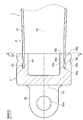
- FIG. 3 is a sectional view taken along the line III-III in FIG. 2 showing a joint structure in the power transmission shaft of the first embodiment.
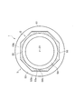
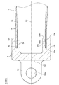
- FIG. 3 is a side sectional view showing the joint structure before the caulking step in the power transmission shaft of the first embodiment.
- It is a flow chart of a manufacturing method of a power transmission shaft of a first embodiment.
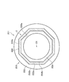
- It is an axial sectional view showing a joint structure in a power transmission shaft of a second embodiment.
- the power transmission shaft 1 of the first embodiment includes a substantially cylindrical tubular body 2 (pipe) extending in the front-rear direction of the vehicle, and a first universal body arranged in front of the tubular body 2.
- a joint 5 (a “connecting member” in the claims) and a second universal joint 6 arranged on the rear side of the tube body 2 are provided.
- the first universal joint 5 of the first embodiment is a cardan joint, and is a metal connecting member for connecting the transmission mounted on the front part of the vehicle body and the power transmission shaft 1.
- the second universal joint 6 of the first embodiment is a constant velocity joint, and is a metal connecting member for connecting the final reduction gear device mounted on the rear portion of the vehicle body and the power transmission shaft 1.
- the tube body 2 is made of carbon fiber reinforced plastic (CFRP).
- CFRP carbon fiber reinforced plastic
- the reinforcing fiber used in the fiber-reinforced plastic in the present invention is not limited to carbon fiber, and may be glass fiber or aramid fiber.
- the tubular body 2 is manufactured by incorporating two construction methods of the filament winding method and the sheet winding method.
- the molded body manufactured by the filament winding method has high mechanical strength (particularly torsional strength) because the continuity of the fibers (carbon fibers) is maintained.
- the carbon fibers can be arranged so as to extend in the axial direction of the mandrel, and a molded product having high elasticity in the axial line O1 direction can be manufactured. That is, according to the manufacturing method described above, a fiber layer made of fibers wound around the axis O1 and a fiber layer made of fibers extending in the direction of the axis O1 are laminated inside the tubular body 102. Therefore, the tubular body 2 having high mechanical strength and high elasticity in the direction of the axis O1 can be manufactured.
- the fibers oriented in the circumferential direction are preferably PAN (Polyacrylonitrile) fibers, and the fibers oriented in the axis O1 direction are preferably pitch fibers.
- the tube body 2 of the present invention is not limited to the above manufacturing method.
- a prepreg may be wound around a mandrel to form a molded body, and continuous carbon fibers may be wound around the outer periphery of the molded body.
- a single manufacturing method (filament winding method or sheet winding method) may be used.
- the tubular body 2 includes a tubular main body portion 10, a first connecting portion 20 arranged on the front side (one end portion) of the main body portion 10, and a second connecting portion 20 arranged on the rear side (other end portion) of the main body portion 10.
- the connecting portion 30 and the inclined portion 40 formed between the main body portion 10 and the second connecting portion 30 are provided.
- the cross-sectional shape of the outer peripheral surface of the main body portion 10 is circular. Further, the outer diameter of the main body portion 10 is reduced from the central portion toward both end portions, and the outer diameter of the central portion is larger than the outer diameters of both end portions. That is, when the main body portion 10 is cut along the axis O1, the cross-sectional shape of the outer peripheral surface of the main body portion 10 is a gentle curved line and has an arc shape protruding toward the outside. Therefore, the outer shape of the main body portion 10 has a barrel shape (barrel shape) in which the central portion bulges outward in the radial direction.
- the cross-sectional shape of the outer peripheral surface of the main body 10 is an arc, but in the present invention, You may form the cross-sectional shape of the outer peripheral surface of the main-body part 10 in step shape. Further, when the main body portion 10 is cut along the axis O1, the cross-sectional shape of the outer peripheral surface of the main body portion 10 may be linearly inclined so as to go toward the center side from the central portion toward both end portions. ..
- the shaft portion (shown in the figure) of the stub shaft 4 of the second universal joint 6 is fitted in the second connecting portion 30.
- the inner peripheral surface of the second connecting portion 30 has a polygonal shape that follows the polygonal outer peripheral surface of the shaft portion of the stub shaft 4. In this way, the tube body 2 and the stub shaft 4 are configured so as not to rotate relative to each other.
- the inclined portion 40 is a portion formed between the main body portion 10 and the second connection portion 30.
- the second connecting portion 30 is continuous with the rear end of the main body portion 10 via the inclined portion 40.
- the outer diameter of the inclined portion 40 gradually decreases from the main body portion 10 toward the second connection portion 30, and has a truncated cone shape.
- the plate thickness of the inclined portion 40 gradually decreases from the end (rear end) on the second connection portion 30 side (rear side) toward the end (front end) on the body portion 10 side (front side). There is. Therefore, the plate thickness of the front end portion of the inclined portion 40 is the thinnest, and the front end portion of the inclined portion 40 constitutes the fragile portion.
- the fragile portion is a portion where the shear strength of the inclined portion 40 is the lowest.
- the plate thickness of the entire inclined portion 40 is changed, but the plate thickness may be changed in a part of the inclined portion 40. Further, the plate thickness of the inclined portion 40 gradually decreases from the end portion (front end portion) on the main body portion 10 side (front side) toward the end portion (rear end portion) on the second connection portion 30 side (rear side). Then, a fragile portion may be provided at the rear end portion of the inclined portion 40.
- the first connecting portion 20 is a portion continuously formed at the front end of the main body portion 10.
- the stub yoke 3 of the first universal joint 5 is fitted to the first connecting portion 20.
- the outer peripheral surface 20b of the first connecting portion 20 has a polygonal cross-sectional shape.
- the outer peripheral shape of the first connecting portion 20 is formed into an octagon.
- the inner peripheral shape of the first connecting portion 20 is circular.
- the stub yoke 3 is a metal member including a base portion 51 and a pair of arms 52 protruding forward from the front surface of the base portion 51.
- a shaft hole 52a into which the joint pin is inserted passes through the arm 52.
- a hollow first pillar portion 53 and a hollow second pillar portion 54 formed inside the first pillar portion 53 are formed at the rear portion of the base portion 51.
- the 1st pillar part 53 and the 2nd pillar part 54 are cylindrical parts centering on axis O1.
- the outer peripheral shape and the inner peripheral shape of the second pillar portion 54 are formed in a circular shape.
- the inner peripheral surface 53a of the first pillar portion 53 has a polygonal cross-sectional shape and the outer peripheral surface 53b has a cross-sectional shape. It is formed in a circular shape.
- the inner peripheral shape of the first pillar portion 53 is formed into an octagon, but the shape is not limited in the present invention, and for example, it may be a quadrangle or a triangle. It may be rectangular or oval other than polygonal.
- the outer peripheral surface 54b of the second pillar portion 54 and the inner peripheral surface 53a of the first pillar portion 53 are arranged with a space therebetween. Therefore, an annular gap 55 is formed between the outer peripheral surface 54b of the second pillar portion 54 and the inner peripheral surface 53a of the first pillar portion 53.
- the cross-sectional shape of the gap 55 is the same as the cross-sectional shape of the first connecting portion 20.
- the front end portion of the first connecting portion 20 is inserted between the outer peripheral surface 54 b of the second pillar portion 54 and the inner peripheral surface 53 a of the first pillar portion 53.
- the inner peripheral surface 53a of the first pillar portion 53 and the outer peripheral surface 20b of the first connecting portion 20 are fitted to each other, and the first connecting portion 20 and the stub yoke 3 are opposed to each other. It is configured to not rotate.
- the first pillar portion 53 is caulked as shown in FIG. In the first embodiment, the entire circumference of the outer peripheral surface 53b of the first pillar portion 53 is pushed in by a tool. Thus, the outer peripheral surface 53b of the first pillar portion 53 is formed with the recessed portion 56 over the entire circumference.
- the first connecting portion 20 is sandwiched between the first pillar portion 53 and the second pillar portion 54 by plastically deforming the first pillar portion 53 inward by caulking.
- the outer periphery 53b of the 1st pillar part 53 is crimped all around, in this invention, you may crimp a plurality of places of the outer peripheral surface 53b of the 1st pillar 53.
- the method for manufacturing the power transmission shaft 1 includes a preparation step of preparing a tube body 2 made of fiber reinforced plastic and a stub yoke 3 made of metal. Further, in the method for manufacturing the power transmission shaft 1, the insertion step of inserting the first connecting portion 20 between the first column portion 53 and the second column portion 54 of the stub yoke 3 and the caulking process on the first column portion 53. Then, the step of crimping the stub yoke 3 to the first connecting portion 20 is performed.
- the tube body 2 and the stub yoke 3 shown in FIG. 1 are prepared (step S1). Subsequently, in the inserting step, as shown in FIG. 4, the front end portion of the first connecting portion 20 of the tubular body 2 is inserted between the first column portion 53 and the second column portion 54 of the stub yoke 3 (step S2). Thereby, as shown in FIG. 3, the inner peripheral surface 53a of the first pillar portion 53 and the outer peripheral surface 20b of the first connecting portion 20 are fitted together.
- the outer peripheral surface 53b of the first pillar portion 53 is pushed by a tool to plastically deform the inside of the first pillar portion 53 toward the inside (step S3).
- the recessed portion 56 is formed on the outer peripheral surface 53b of the first pillar portion 53.
- the front end portion of the first connection portion 20 is sandwiched between the first pillar portion 53 and the second pillar portion 54. In this way, the stub yoke 3 is joined to the first connecting portion 20.
- the first connecting portion 20 is inserted between the first pillar portion 53 and the second pillar portion 54, and By caulking the column portion 53, the joining force between the first connecting portion 20 and the stub yoke 3 in the rotation direction can be increased. Further, in the power transmission shaft 1 and the manufacturing method thereof, the processing of the first connecting portion 20 and the stub yoke 3 can be simplified, so that the cost can be reduced.
- tubular body 2 of the power transmission shaft 1 since the outer diameter of the central portion of the main body portion 10 where bending stress is likely to be concentrated is formed to be large, a predetermined bending strength is obtained. doing. Further, since the tubular body 2 of the power transmission shaft 1 is formed of fiber reinforced plastic, the freedom of design is high and the cost can be further reduced.
- the power transmission shaft 101 of the second embodiment includes a pipe body 2, a first universal joint 5 arranged on the front side of the pipe body 2, and a first universal joint 5 arranged on the rear side of the pipe body 2.
- the two universal joints 6 are provided.
- the tube body 2 is arranged on the main body portion 10 (see FIG. 1 ), the first connecting portion 120 arranged on the front side (one end portion) of the main body portion 10, and the rear side (other end portion) on the main body portion 10.
- the second connection portion 30 (see FIG. 1).
- the inner peripheral surface 120a has a polygonal cross-sectional shape and the outer peripheral surface 120b has a cross-sectional shape. It is formed in a circular shape.
- the outer peripheral surface 153b has a polygonal cross-sectional shape.
- the inner peripheral shape of the first column portion 153 is formed in a circular shape.
- the front end portion of the first connecting portion 120 is inserted between the outer peripheral surface 154b of the second pillar portion 154 and the inner peripheral surface 153a of the first pillar portion 153.
- the outer peripheral surface 154b of the second column portion 154 and the inner peripheral surface 120a of the first connecting portion 120 are fitted together.
- the outer peripheral surface 153b of the first pillar portion 153 is caulked.
- the 1st connection part 120 is inserted between the 1st pillar part 153 and the 2nd pillar part 154, and the 1st pillar part 153 is caulked. It is possible to increase the joining force between the connecting portion 120 and the stub yoke 103 in the rotation direction.
- the processing of the first connection portion 120 and the stub yoke 103 can be simplified, so that the cost is reduced. Can be planned.
- the power transmission shaft 201 according to the third embodiment of the present invention includes a pipe body 2, a first universal joint 5 arranged on the front side of the pipe body 2, and a first universal joint 5 arranged on the rear side of the pipe body 2.
- the two universal joints 6 are provided.
- the tube body 2 is arranged on the main body portion 10 (see FIG. 1 ), the first connecting portion 220 arranged on the front side (one end portion) of the main body portion 10, and the rear side (other end portion) on the main body portion 10.
- the second connection portion 30 (see FIG. 1).
- the cross-sectional shapes of the inner peripheral surface 220a and the outer peripheral surface 220b are polygonal.
- the inner peripheral surface 253a has a polygonal cross-sectional shape.
- the outer peripheral surface 254b has a polygonal cross-sectional shape.
- the front end portion of the first connecting portion 220 is inserted between the inner peripheral surface 253a of the first pillar portion 253 and the outer peripheral surface 254b of the second pillar portion 254.
- the outer peripheral surface 254b of the second pillar portion 254 and the inner peripheral surface 220a of the first connecting portion 220 are fitted together, and the inner peripheral surface 253a of the first pillar portion 253 and the outer periphery of the first connecting portion 220 are fitted together.
- the surface 220b is fitted.
- the outer peripheral surface 253b of the first pillar portion 253 is caulked.
- the 1st connection part 220 is inserted between the 1st pillar part 253 and the 2nd pillar part 254, and the 1st pillar part 253 is crimped.
- the joining force between the connecting portion 220 and the stub yoke 203 in the rotation direction can be increased.
- the machining of the first connection portion 220 and the stub yoke 203 can be simplified, so that the cost is reduced. Can be planned.
- the power transmission shaft 301 of the fourth embodiment includes a pipe body 2, a first universal joint 5 arranged on the front side of the pipe body 2, and a first universal joint 5 arranged on the rear side of the pipe body 2.
- the two universal joints 6 are provided.
- the tubular body 2 includes a main body portion 10, a first connecting portion 20 arranged on the front side (one end portion) of the main body portion 10, and a second connecting portion 30 arranged on the rear side (other end portion) of the main body portion 10. (See FIG. 1).
- the stub yoke 303 of the fourth embodiment is provided with a hollow first pillar portion 353 and a second pillar portion 354 formed inside the first pillar portion 353. It is inserted between the one pillar portion 353 and the second pillar portion 354. Further, the outer peripheral surface 353b of the first pillar portion 353 is caulked. Further, in the stub yoke 303 of the fourth embodiment, the inside 354c of the second pillar portion 354 is filled. That is, the second pillar portion 354 of the fourth embodiment is solid.
- the first connecting portion 20 is inserted between the first pillar portion 353 and the second pillar portion 354, and the first pillar portion 353 is caulked, whereby the first connecting portion is formed. It is possible to increase the joining force between the stub 20 and the stub yoke 303 in the rotational direction.
- the machining of the first connection portion 20 and the stub yoke 303 can be simplified, so that the cost is reduced. Can be planned.
- the power transmission shaft 401 of the fifth embodiment includes a pipe body 2, a first universal joint 5 arranged on the front side of the pipe body 2, and a first universal joint 5 arranged on the rear side of the pipe body 2.
- the two universal joints 6 are provided.
- the tubular body 2 includes a main body portion 410, a first connecting portion 20 arranged on the front side (one end portion) of the main body portion 410, and a second connecting portion 30 arranged on the rear side (other end portion) of the main body portion 410. And are equipped with.
- the stub yoke 3 of the fifth embodiment is provided with a hollow first pillar portion 53 (see FIG. 2) and a second pillar portion 54 (see FIG. 2) formed inside the first pillar portion 53.
- the first connecting portion 20 is inserted between the first pillar portion 53 and the second pillar portion 54. Further, the outer peripheral surface of the first pillar portion 53 is caulked.
- the outer diameter of the main body 410 of the fifth embodiment is uniform from the front end to the rear end. That is, the outer shape of the main body 410 of the fifth embodiment is a straight cylindrical body.
- the outer diameter of the main body portion 410 of the fifth embodiment is uniform from the front end portion to the rear end portion, in the present invention, the outer diameter of the main body portion 410 is reduced from the central portion toward the one end portion. The diameter may be increased, and the diameter may be uniformly formed from the center to the other end.
- the first connecting portion 20 is inserted between the first column portion 53 (see FIG. 2) and the second column portion 54 (see FIG. 2), and the first column portion 53 is inserted.
- caulking it is possible to increase the joining force between the first connecting portion 20 and the stub yoke 3 in the rotation direction.
- the processing of the first connection portion 20 and the stub yoke 3 can be simplified, and the main body portion 410 can be formed. Since it is easy to mold, the cost can be reduced.
- the power transmission shaft 501 according to the sixth embodiment of the present invention includes a tubular body 2, a first universal joint 5 (see FIG. 1) arranged on the front side of the tubular body 2, and a rear side of the tubular body 2. And a second universal joint 6 (see FIG. 1).
- the tube body 2 includes a main body portion 10 (see FIG. 1 ), a first connecting portion 20 arranged on the front side of the main body portion 10, and a second connecting portion 30 arranged on the rear side of the main body portion 10 (see FIG. 1 ). ), and are provided.
- a hollow first pillar portion 53 and a second pillar portion 554 formed inside the first pillar portion 53 are formed, and the first connection portion 20 has a first connecting portion 20. It is inserted between the one pillar portion 53 and the second pillar portion 554. Further, the outer peripheral surface of the first pillar portion 53 is caulked.
- the second pillar portion 554 of the sixth embodiment is divided in the circumferential direction and is composed of a plurality of members.
- the machining of the first connecting portion 20 and the stub yoke 503 can be simplified, so that the cost is reduced. Can be planned.
- the second column portion 554 can be bent inward in the radial direction, and therefore the inner peripheral surface 53a of the first column portion 53 and the outer peripheral surface 554b of the second column portion 554.
- the first connecting portion 20 can be smoothly inserted between the and.
- the present invention is not limited to the examples described in the respective embodiments.
- the structure of the present invention is applied to the joint structure between the first connecting portion and the stub yoke (connecting member), but the present invention is applied to the joint structure between the second connecting portion and the stub shaft (connecting member).
- the configuration of the invention may be applied.
- the front side of the main body is the one end and the rear side of the main body is the other end for convenience of description, but the present invention is not limited to this.
- the front side of the main body may be the other end and the rear side may be the one end.
- Second universal joint 10 410 Main body portion 20, 120, 220 First connection part 30 Second connection part 40 Inclined part 51 Base part 52 Arm 53,153,253,353 First column part 54,154,254,354,554 Second column part 56 Dimple part O1 axis
Landscapes
- Engineering & Computer Science (AREA)
- General Engineering & Computer Science (AREA)
- Mechanical Engineering (AREA)
- Ocean & Marine Engineering (AREA)
- Shafts, Cranks, Connecting Bars, And Related Bearings (AREA)
Abstract
繊維強化プラスチック製の管体(2)と、管体(2)の端部に接続された金属製のスタブヨーク(3)と、により構成された動力伝達軸(1)である。スタブヨーク(3)は、中空に形成された第一柱部(53)と、第一柱部(53)の内部に形成された第二柱部(54)と、を有している。管体(2)の端部には、スタブヨーク(3)が接続される第一接続部(20)が形成され、第一接続部(20)は、第一柱部(53)と第二柱部(54)との間に挿入されており、第一柱部(53)にかしめ加工が施されている。この構成では、動力伝達軸(1)の低コスト化を図れるとともに、管体(2)とスタブヨーク(3)との回転方向の接合力を高めることができる。
Description
本発明は、動力伝達軸及びその製造方法に関する。
車両に搭載される動力伝達軸(プロペラシャフト)は、車両の前後方向に延在しており、原動機で発生して変速機で減速された動力を終減速装置に伝達している。
前記した動力伝達軸は、筒状の本体部と、本体部の端部に連続している筒状の接続部と、スタブヨークとを備えている。そして、スタブヨークは、中空に形成された第一柱部と、第一柱部の内部に形成された第二柱部と、を有しており、接続部を第一柱部と第二柱部との間に挿入することで、接続部にスタブヨークを接合しているものがある(例えば、特許文献1参照)。
前記した動力伝達軸は、筒状の本体部と、本体部の端部に連続している筒状の接続部と、スタブヨークとを備えている。そして、スタブヨークは、中空に形成された第一柱部と、第一柱部の内部に形成された第二柱部と、を有しており、接続部を第一柱部と第二柱部との間に挿入することで、接続部にスタブヨークを接合しているものがある(例えば、特許文献1参照)。
前記した従来の動力伝達軸では、接続部の外周面及び第一柱部の内周面にセレーション加工を施して溝面を形成している。そして、接続部の溝面と第一柱部の溝面とを嵌め合わせることで、接続部とスタブヨークとの回転方向の接合力を高めている。
このように、接続部及びスタブヨークにセレーション加工を施す構成では、製造コストが増加するという問題がある。
このように、接続部及びスタブヨークにセレーション加工を施す構成では、製造コストが増加するという問題がある。
本発明は、前記した問題を解決し、低コスト化を図れるとともに、接続部と連結部材との回転方向の接合力を高めることができる動力伝達軸及びその製造方法を提供することを課題とする。
前記課題を解決するため、第一の発明は、繊維強化プラスチック製の管体と、前記管体の端部に接続された金属製の連結部材と、により構成され、回転することで動力を伝達する動力伝達軸である。前記連結部材は、中空に形成された第一柱部と、前記第一柱部の内部に形成された第二柱部と、を有している。前記管体は、本体部と、前記本体部の端部に連続し、前記連結部材が接続される接続部と、により形成されている。前記接続部は、前記第一柱部と前記第二柱部との間に挿入されており、前記第一柱部にかしめ加工が施されている。
前記課題を解決するため、第二の発明は、繊維強化プラスチック製の管体と、前記管体の端部に接続された金属製の連結部材と、により構成され、回転することで動力を伝達する動力伝達軸の製造方法である。この製造方法は、まず、前記連結部材が接続される接続部が端部に形成された前記管体と、中空の第一柱部と前記第一柱部の内部に形成された第二柱部とを有する金属製の前記連結部材と、を用意する準備工程を備えている。続いて、前記接続部を前記第一柱部と前記第二柱部との間に挿入する挿入工程を備えている。さらに、前記第一柱部にかしめ加工を施して、前記接続部に前記連結部材を接合するかしめ工程を備えている。
本発明では、接続部を連結部材の第一柱部と第二柱部との間に挿入した後に、第一柱部の外周面をかしめることで、接続部と連結部材との回転方向の接合力を高めることができる。そして、本発明の動力伝達軸及びその製造方法では、接続部及び連結部材の加工を簡素化できるため、低コスト化を図ることができる。
続いて、各実施形態の動力伝達軸について図面を参照しながら説明する。なお、各実施形態では、本発明の動力伝達軸を、FF(Front-engine Front-drive)ベースの四輪駆動車に搭載されるプロペラシャフトに適用した例を挙げる。また、各実施形態で共通する技術的要素には、共通の符号を付し、説明を省略する。
[第一実施形態]
図1に示すように、第一実施形態の動力伝達軸1は、車両の前後方向に延在する略円筒状の管体2(パイプ)と、管体2の前側に配置された第一自在継手5(特許請求の範囲における「連結部材」)と、管体2の後側に配置された第二自在継手6と、を備えている。
図1に示すように、第一実施形態の動力伝達軸1は、車両の前後方向に延在する略円筒状の管体2(パイプ)と、管体2の前側に配置された第一自在継手5(特許請求の範囲における「連結部材」)と、管体2の後側に配置された第二自在継手6と、を備えている。
第一実施形態の第一自在継手5は、カルダンジョイントであり、車体の前部に搭載された変速機と動力伝達軸1とを連結するための金属製の連結部材である。
第一実施形態の第二自在継手6は、等速ジョイントであり、車体の後部に搭載された終減速装置と動力伝達軸1とを連結するための金属製の連結部材である。
そして、変速機から動力伝達軸1に動力(トルク)が伝達すると、動力伝達軸1が軸線O1回りに回転して、終減速装置に動力が伝達される。
第一実施形態の第二自在継手6は、等速ジョイントであり、車体の後部に搭載された終減速装置と動力伝達軸1とを連結するための金属製の連結部材である。
そして、変速機から動力伝達軸1に動力(トルク)が伝達すると、動力伝達軸1が軸線O1回りに回転して、終減速装置に動力が伝達される。
管体2は、炭素繊維強化プラスチック(CFRP)製に形成されている。なお、本発明において繊維強化プラスチックに使用される強化繊維は、炭素繊維に限られず、ガラス繊維やアラミド繊維であってもよい。
管体2の製造方法は、図示しないマンドレルに連続炭素繊維を巻き付けて成形体を形成し、その後、成形体の外周にプリプレグ(炭素繊維に樹脂を含浸させたシート)を巻き付けている。よって、管体2は、フィラメントワインディング法とシートワインディング法との二つの工法を取り入れられて製造されている。
ここで、フィラメントワインディング法によって製造される成形体は、繊維(炭素繊維)の連続性が保たれるため機械的強度(特にねじり強度)が高い。
また、シートワインディング法によれば、炭素繊維をマンドレルの軸線方向に延在するように配置することができ、軸線O1方向に高弾性化した成形体を製造できる。
つまり、上記した製造方法によれば、管体102の内部で、軸O1回りに巻回された繊維からなる繊維層と、軸線O1方向に延在する繊維からなる繊維層と、が積層しており、機械的強度が高く、かつ、軸線O1方向に高弾性化した管体2を製造できる。
なお、周方向に配向する繊維としてPAN系(Polyacrylonitrile)繊維が好ましく、軸線O1方向に配向する繊維としてピッチ繊維が好ましい。
ここで、フィラメントワインディング法によって製造される成形体は、繊維(炭素繊維)の連続性が保たれるため機械的強度(特にねじり強度)が高い。
また、シートワインディング法によれば、炭素繊維をマンドレルの軸線方向に延在するように配置することができ、軸線O1方向に高弾性化した成形体を製造できる。
つまり、上記した製造方法によれば、管体102の内部で、軸O1回りに巻回された繊維からなる繊維層と、軸線O1方向に延在する繊維からなる繊維層と、が積層しており、機械的強度が高く、かつ、軸線O1方向に高弾性化した管体2を製造できる。
なお、周方向に配向する繊維としてPAN系(Polyacrylonitrile)繊維が好ましく、軸線O1方向に配向する繊維としてピッチ繊維が好ましい。
なお、本発明の管体2は、上記した製造方法に限定されない。管体2の製造方法としては、マンドレルにプリプレグを巻き付けて成形体を形成し、その成形体の外周に連続炭素繊維を巻き付けてもよい。又は、管体2の製造方法としては、単一の製造方法(フィラメントワインディング法又はシートワインディング法)を用いてもよい。
管体2は、筒状の本体部10と、本体部10の前側(一端部)に配置された第一接続部20と、本体部10の後側(他端部)に配置された第二接続部30と、本体部10と第二接続部30との間に形成された傾斜部40と、を備えている。
軸線O1を法線とする平面で本体部10を切った場合には、本体部10の外周面の断面形状は円形状となっている。
また、本体部10の外径は、中央部から両端部に向うに連れて縮径しており、中央部の外径は、両端部の外径よりも大きい。
つまり、軸線O1に沿って本体部10を切った場合には、本体部10の外周面の断面形状は、緩やかな曲線を描き、外側に向けて突出する円弧状となっている。よって、本体部10の外形は、中央部が径方向外側に膨らんだ樽形状(バレル形状)となっている。
また、本体部10の外径は、中央部から両端部に向うに連れて縮径しており、中央部の外径は、両端部の外径よりも大きい。
つまり、軸線O1に沿って本体部10を切った場合には、本体部10の外周面の断面形状は、緩やかな曲線を描き、外側に向けて突出する円弧状となっている。よって、本体部10の外形は、中央部が径方向外側に膨らんだ樽形状(バレル形状)となっている。
なお、第一実施形態の動力伝達軸1では、軸線O1に沿って本体部10を切った場合に、本体部10の外周面の断面形状は円弧状となっているが、本発明においては、本体部10の外周面の断面形状を階段状に形成してもよい。
また、軸線O1に沿って本体部10を切った場合に、本体部10の外周面の断面形状が中央部から両端部に向かうに連れて中心側に向かうように直線状に傾斜させてもよい。
また、軸線O1に沿って本体部10を切った場合に、本体部10の外周面の断面形状が中央部から両端部に向かうに連れて中心側に向かうように直線状に傾斜させてもよい。
第二接続部30内には、第二自在継手6のスタブシャフト4のシャフト部(図示ぜす)が嵌め込まれている。第二接続部30の内周面は、スタブシャフト4のシャフト部の多角形状の外周面に倣った多角形状を呈している。このように、管体2とスタブシャフト4とが互いに相対回転しないように構成されている。
傾斜部40は、本体部10と第二接続部30との間に形成された部位である。第二接続部30は、傾斜部40を介して本体部10の後端に連続している。傾斜部40の外径は、本体部10から第二接続部30に向かうに連れて次第に縮径し、円錐台形状となっている。
傾斜部40の板厚は、第二接続部30側(後側)の端部(後端部)から本体部10側(前側)の端部(前端部)に向かうに連れて漸次薄くなっている。このため、傾斜部40のうち前端部の板厚が最も薄くなっており、傾斜部40の前端部が脆弱部を構成している。脆弱部は、傾斜部40のせん断強度が最も低下している部位である。
なお、管体2では、傾斜部40全体の板厚が変化しているが、傾斜部40の一部区間において板厚を変化させてもよい。
また、傾斜部40の板厚を、本体部10側(前側)の端部(前端部)から第二接続部30側(後側)の端部(後端部)に向かうに連れて漸次薄くして、傾斜部40の後端部に脆弱部を設けてもよい。
傾斜部40の板厚は、第二接続部30側(後側)の端部(後端部)から本体部10側(前側)の端部(前端部)に向かうに連れて漸次薄くなっている。このため、傾斜部40のうち前端部の板厚が最も薄くなっており、傾斜部40の前端部が脆弱部を構成している。脆弱部は、傾斜部40のせん断強度が最も低下している部位である。
なお、管体2では、傾斜部40全体の板厚が変化しているが、傾斜部40の一部区間において板厚を変化させてもよい。
また、傾斜部40の板厚を、本体部10側(前側)の端部(前端部)から第二接続部30側(後側)の端部(後端部)に向かうに連れて漸次薄くして、傾斜部40の後端部に脆弱部を設けてもよい。
第一接続部20は、本体部10の前端に連続して形成されている部位である。
第一接続部20には、第一自在継手5のスタブヨーク3が嵌め合わされている。図3に示すように、軸線O1を法線とする平面で第一接続部20を切った場合には、第一接続部20の外周面20bの断面形状が多角形となっている。第一実施形態では、第一接続部20の外周形状が八角形に形成されている。なお、第一接続部20の内周形状は、円形に形成されている。
第一接続部20には、第一自在継手5のスタブヨーク3が嵌め合わされている。図3に示すように、軸線O1を法線とする平面で第一接続部20を切った場合には、第一接続部20の外周面20bの断面形状が多角形となっている。第一実施形態では、第一接続部20の外周形状が八角形に形成されている。なお、第一接続部20の内周形状は、円形に形成されている。
スタブヨーク3は、図2に示すように、基部51と、基部51の前面から前方に突出した一対のアーム52と、を備えている金属部材である。アーム52には、ジョイントピンが差し込まれる軸孔52aが貫通している。
基部51の後部には、図3に示すように、中空な第一柱部53と、第一柱部53の内部に形成された中空な第二柱部54と、が形成されている。第一柱部53及び第二柱部54は、軸線O1を中心軸する筒状の部位である。第二柱部54は、外周形状及び内周形状が円形に形成されている。
軸線O1を法線とする平面で第一柱部53を切った場合には、第一柱部53の内周面53aの断面形状が多角形に形成されるとともに、外周面53bの断面形状が円形に形成されている。
なお、第一実施形態では、第一柱部53の内周形状が八角形に形成されているが、本発明においては、その形状は限定されるものではなく、例えば、四角形や三角形などの多角形、又は、多角形以外の長円形でもよい。
第二柱部54の外周面54bと、第一柱部53の内周面53aとは間隔を空けて配置されている。したがって、第二柱部54の外周面54bと、第一柱部53の内周面53aとの間には、環状の隙間55が形成されている。
軸線O1を法線とする平面で第一柱部53及び第二柱部54を切った場合に、隙間55の断面形状が第一接続部20の断面形状と同じ形状となっている。
そして、図2に示すように、第二柱部54の外周面54bと、第一柱部53の内周面53aとの間に、第一接続部20の前端部が挿入されている。
これにより、図3に示すように、第一柱部53の内周面53aと、第一接続部20の外周面20bとが嵌め合わされており、第一接続部20とスタブヨーク3とが互いに相対回転しないように構成されている。
そして、図2に示すように、第二柱部54の外周面54bと、第一柱部53の内周面53aとの間に、第一接続部20の前端部が挿入されている。
これにより、図3に示すように、第一柱部53の内周面53aと、第一接続部20の外周面20bとが嵌め合わされており、第一接続部20とスタブヨーク3とが互いに相対回転しないように構成されている。
第一柱部53には、図2に示すように、かしめ加工が施されている。第一実施形態では、第一柱部53の外周面53bの全周を工具によって押し込んでいる。これにより、第一柱部53の外周面53bには、全周に亘って窪み部56が形成されている。
第一柱部53をかしめ加工により内側に向けて塑性変形させることで、第一接続部20が第一柱部53と第二柱部54との間に挟み込まれている。
なお、第一実施形態では、第一柱部53の外周面53bの全周をかしめているが、本発明においては、第一柱部53の外周面53bの複数の箇所をかしめてもよい。
なお、第一実施形態では、第一柱部53の外周面53bの全周をかしめているが、本発明においては、第一柱部53の外周面53bの複数の箇所をかしめてもよい。
次に、第一実施形態の動力伝達軸1の製造方法について説明する。なお、以下の説明においては図5のフローチャートを適宜に参照する。
動力伝達軸1の製造方法は、繊維強化プラスチック製の管体2と金属製のスタブヨーク3と、を用意する準備工程を備えている。さらに、動力伝達軸1の製造方法は、第一接続部20をスタブヨーク3の第一柱部53と第二柱部54との間に挿入する挿入工程と、第一柱部53にかしめ加工を施して、第一接続部20にスタブヨーク3を接合するかしめ工程と、を備えている。
動力伝達軸1の製造方法は、繊維強化プラスチック製の管体2と金属製のスタブヨーク3と、を用意する準備工程を備えている。さらに、動力伝達軸1の製造方法は、第一接続部20をスタブヨーク3の第一柱部53と第二柱部54との間に挿入する挿入工程と、第一柱部53にかしめ加工を施して、第一接続部20にスタブヨーク3を接合するかしめ工程と、を備えている。
まず、準備工程において、図1に示す管体2及びスタブヨーク3を用意する(ステップS1)。続いて、挿入工程では、図4に示すように、管体2の第一接続部20の前端部を、スタブヨーク3の第一柱部53と第二柱部54との間に挿入する(ステップS2)。これにより、図3に示すように、第一柱部53の内周面53aと、第一接続部20の外周面20bとが嵌め合わされる。
さらに、かしめ工程では、図2に示すように、第一柱部53の外周面53bを工具によって押し込んで、第一柱部53の内部を内側に向けて塑性変形させる(ステップS3)。これにより、第一柱部53の外周面53bに窪み部56が形成される。また、第一接続部20の前端部が第一柱部53と第二柱部54との間に挟み込まれる。このようにして、第一接続部20にスタブヨーク3が接合される。
以上、第一実施形態の動力伝達軸1及びその製造方法では、図3に示すように、第一接続部20を第一柱部53と第二柱部54との間に挿入し、第一柱部53をかしめることで、第一接続部20とスタブヨーク3との回転方向の接合力を高めることができる。そして、動力伝達軸1及びその製造方法では、第一接続部20及びスタブヨーク3の加工を簡素化できるため、低コスト化を図ることができる。
また、動力伝達軸1の管体2では、図1に示すように、曲げ応力が集中し易い本体部10の中央部の外径が大径に形成されているため、所定の曲げ強度を有している。
また、動力伝達軸1の管体2は、繊維強化プラスチックにより形成されているため、設計の自由が高く、更なる低コスト化を図れる。
また、動力伝達軸1の管体2は、繊維強化プラスチックにより形成されているため、設計の自由が高く、更なる低コスト化を図れる。
[第二実施形態]
次に、本発明の第二実施形態に係る動力伝達軸101について説明する。
第二実施形態の動力伝達軸101は、図6に示すように、管体2と、管体2の前側に配置された第一自在継手5と、管体2の後側に配置された第二自在継手6(図1参照)と、を備えている。
管体2は、本体部10(図1参照)と、本体部10の前側(一端部)に配置された第一接続部120と、本体部10の後側(他端部)に配置された第二接続部30(図1参照)と、を備えている。
次に、本発明の第二実施形態に係る動力伝達軸101について説明する。
第二実施形態の動力伝達軸101は、図6に示すように、管体2と、管体2の前側に配置された第一自在継手5と、管体2の後側に配置された第二自在継手6(図1参照)と、を備えている。
管体2は、本体部10(図1参照)と、本体部10の前側(一端部)に配置された第一接続部120と、本体部10の後側(他端部)に配置された第二接続部30(図1参照)と、を備えている。
第二実施形態の第一接続部120を、軸線O1を法線とする平面で切った場合には、内周面120aの断面形状が多角形に形成されるとともに、外周面120bの断面形状が円形に形成されている。
第二実施形態のスタブヨーク103の第二柱部154を、軸線O1を法線とする平面で切った場合には、外周面153bの断面形状が多角形となっている。
第二実施形態のスタブヨーク103では、第一柱部153の内周形状は円形に形成されている。
第二実施形態のスタブヨーク103では、第一柱部153の内周形状は円形に形成されている。
第二柱部154の外周面154bと、第一柱部153の内周面153aとの間には、第一接続部120の前端部が挿入されている。これにより、第二柱部154の外周面154bと、第一接続部120の内周面120aとが嵌め合わされている。また、第一柱部153の外周面153bには、かしめ加工が施されている。
そして、第二実施形態の動力伝達軸101では、第一接続部120を第一柱部153と第二柱部154との間に挿入し、第一柱部153をかしめることで、第一接続部120とスタブヨーク103との回転方向の接合力を高めることができる。
以上、第二実施形態の動力伝達軸101では、第一実施形態の動力伝達軸1(図3参照)と同様に、第一接続部120及びスタブヨーク103の加工を簡素化できるため、低コスト化を図ることができる。
[第三実施形態]
次に、本発明の第三実施形態に係る動力伝達軸201について説明する。
第三実施形態の動力伝達軸201は、図7に示すように、管体2と、管体2の前側に配置された第一自在継手5と、管体2の後側に配置された第二自在継手6(図1参照)と、を備えている。
管体2は、本体部10(図1参照)と、本体部10の前側(一端部)に配置された第一接続部220と、本体部10の後側(他端部)に配置された第二接続部30(図1参照)と、を備えている。
次に、本発明の第三実施形態に係る動力伝達軸201について説明する。
第三実施形態の動力伝達軸201は、図7に示すように、管体2と、管体2の前側に配置された第一自在継手5と、管体2の後側に配置された第二自在継手6(図1参照)と、を備えている。
管体2は、本体部10(図1参照)と、本体部10の前側(一端部)に配置された第一接続部220と、本体部10の後側(他端部)に配置された第二接続部30(図1参照)と、を備えている。
第三実施形態の第一接続部220を、軸線O1を法線とする平面で切った場合には、内周面220a及び外周面220bの断面形状が多角形となっている。
第三実施形態のスタブヨーク203の第一柱部253を、軸線O1を法線とする平面で切った場合には、内周面253aの断面形状が多角形となっている。
第三実施形態のスタブヨーク203の第二柱部254を、軸線O1を法線とする平面で切った場合には、外周面254bの断面形状が多角形となっている。
第三実施形態のスタブヨーク203の第二柱部254を、軸線O1を法線とする平面で切った場合には、外周面254bの断面形状が多角形となっている。
第一柱部253の内周面253aと、第二柱部254の外周面254bとの間には、第一接続部220の前端部が挿入されている。これにより、第二柱部254の外周面254bと、第一接続部220の内周面220aとが嵌め合わされるとともに、第一柱部253の内周面253aと、第一接続部220の外周面220bとが嵌め合わされている。また、第一柱部253の外周面253bには、かしめ加工が施されている。
そして、第三実施形態の動力伝達軸201では、第一接続部220を第一柱部253と第二柱部254との間に挿入し、第一柱部253をかしめることで、第一接続部220とスタブヨーク203との回転方向の接合力を高めることができる。
以上、第三実施形態の動力伝達軸201では、第一実施形態の動力伝達軸1(図3参照)と同様に、第一接続部220及びスタブヨーク203の加工を簡素化できるため、低コスト化を図ることができる。
[第四実施形態]
次に、本発明の第四実施形態に係る動力伝達軸301について説明する。
第四実施形態の動力伝達軸301は、図8に示すように、管体2と、管体2の前側に配置された第一自在継手5と、管体2の後側に配置された第二自在継手6(図1参照)と、を備えている。
管体2は、本体部10と、本体部10の前側(一端部)に配置された第一接続部20と、本体部10の後側(他端部)に配置された第二接続部30(図1参照)と、を備えている。
次に、本発明の第四実施形態に係る動力伝達軸301について説明する。
第四実施形態の動力伝達軸301は、図8に示すように、管体2と、管体2の前側に配置された第一自在継手5と、管体2の後側に配置された第二自在継手6(図1参照)と、を備えている。
管体2は、本体部10と、本体部10の前側(一端部)に配置された第一接続部20と、本体部10の後側(他端部)に配置された第二接続部30(図1参照)と、を備えている。
第四実施形態のスタブヨーク303には、中空な第一柱部353と、第一柱部353の内部に形成された第二柱部354と、が形成されており、第一接続部20が第一柱部353と第二柱部354との間に挿入されている。また、第一柱部353の外周面353bにかしめ加工が施されている。
さらに、第四実施形態のスタブヨーク303では、第二柱部354の内部354cが埋められている。つまり、第四実施形態の第二柱部354は中実である。
さらに、第四実施形態のスタブヨーク303では、第二柱部354の内部354cが埋められている。つまり、第四実施形態の第二柱部354は中実である。
第四実施形態の動力伝達軸301では、第一接続部20を第一柱部353と第二柱部354との間に挿入し、第一柱部353をかしめることで、第一接続部20とスタブヨーク303との回転方向の接合力を高めることができる。
以上、第四実施形態の動力伝達軸301では、第一実施形態の動力伝達軸1(図2参照)と同様に、第一接続部20及びスタブヨーク303の加工を簡素化できるため、低コスト化を図ることができる。
[第五実施形態]
次に、本発明の第五実施形態に係る動力伝達軸401について説明する。
第五実施形態の動力伝達軸401は、図9に示すように、管体2と、管体2の前側に配置された第一自在継手5と、管体2の後側に配置された第二自在継手6(図1参照)と、を備えている。
管体2は、本体部410と、本体部410の前側(一端部)に配置された第一接続部20と、本体部410の後側(他端部)に配置された第二接続部30と、を備えている。
次に、本発明の第五実施形態に係る動力伝達軸401について説明する。
第五実施形態の動力伝達軸401は、図9に示すように、管体2と、管体2の前側に配置された第一自在継手5と、管体2の後側に配置された第二自在継手6(図1参照)と、を備えている。
管体2は、本体部410と、本体部410の前側(一端部)に配置された第一接続部20と、本体部410の後側(他端部)に配置された第二接続部30と、を備えている。
第五実施形態のスタブヨーク3には、中空な第一柱部53(図2参照)と、第一柱部53の内部に形成された第二柱部54(図2参照)と、が形成されており、第一接続部20が第一柱部53と第二柱部54との間に挿入されている。また、第一柱部53の外周面には、かしめ加工が施されている。
第五実施形態の本体部410の外径は、前端部から後端部まで均一である。つまり、第五実施形態の本体部410の外形は、ストレートな円筒体となっている。
なお、第五実施形態の本体部410の外径は、前端部から後端部まで均一であるが、本発明においては、本体部410の外径を中央部から一端部に向かうに連れて縮径するとともに、中央部から他端部まで均一に形成してもよい。
第五実施形態の動力伝達軸401では、第一接続部20を第一柱部53(図2参照)と第二柱部54(図2参照)との間に挿入し、第一柱部53をかしめることで、第一接続部20とスタブヨーク3との回転方向の接合力を高めることができる。
以上、第五実施形態の動力伝達軸401では、第一実施形態の動力伝達軸1(図1参照)と同様に、第一接続部20及びスタブヨーク3の加工を簡素化できるとともに、本体部410の成形が容易になるため、低コスト化を図ることができる。
[第六実施形態]
次に、本発明の第六実施形態に係る動力伝達軸501について説明する。
第六実施形態の動力伝達軸501は、図10に示すように、管体2と、管体2の前側に配置された第一自在継手5(図1参照)と、管体2の後側に配置された第二自在継手6(図1参照)と、を備えている。
管体2は、本体部10(図1参照)と、本体部10の前側に配置された第一接続部20と、本体部10の後側に配置された第二接続部30(図1参照)と、を備えている。
次に、本発明の第六実施形態に係る動力伝達軸501について説明する。
第六実施形態の動力伝達軸501は、図10に示すように、管体2と、管体2の前側に配置された第一自在継手5(図1参照)と、管体2の後側に配置された第二自在継手6(図1参照)と、を備えている。
管体2は、本体部10(図1参照)と、本体部10の前側に配置された第一接続部20と、本体部10の後側に配置された第二接続部30(図1参照)と、を備えている。
第五実施形態のスタブヨーク503には、中空な第一柱部53と、第一柱部53の内部に形成された第二柱部554と、が形成されており、第一接続部20が第一柱部53と第二柱部554との間に挿入されている。また、第一柱部53の外周面には、かしめ加工が施されている。
第六実施形態の第二柱部554は、周方向に分割されており、複数の部材によって構成されている。
第六実施形態の第二柱部554は、周方向に分割されており、複数の部材によって構成されている。
以上、第六実施形態の動力伝達軸501では、第一実施形態の動力伝達軸1(図2参照)と同様に、第一接続部20及びスタブヨーク503の加工を簡素化できるため、低コスト化を図ることができる。
また、第六実施形態の動力伝達軸501では、第二柱部554が径方向内側に撓むことができるため、第一柱部53の内周面53aと第二柱部554の外周面554bとの間に第一接続部20をスムーズに挿入できる。
また、第六実施形態の動力伝達軸501では、第二柱部554が径方向内側に撓むことができるため、第一柱部53の内周面53aと第二柱部554の外周面554bとの間に第一接続部20をスムーズに挿入できる。
以上、各実施形態について説明したが、本発明は各実施形態で説明した例に限定されない。
例えば、各実施形態では、第一接続部とスタブヨーク(連結部材)との接合構造に本発明の構成を適用しているが、第二接続部とスタブシャフト(連結部材)との接合構造に本発明の構成を適用してもよい。
また、各実施形態において、説明の都合上、本体部の前側を一端部、本体部の後側を他端部としているが、これに限定されるものではない。例えば、本体部の前側を他端部、後側を一端部としてもよい。
例えば、各実施形態では、第一接続部とスタブヨーク(連結部材)との接合構造に本発明の構成を適用しているが、第二接続部とスタブシャフト(連結部材)との接合構造に本発明の構成を適用してもよい。
また、各実施形態において、説明の都合上、本体部の前側を一端部、本体部の後側を他端部としているが、これに限定されるものではない。例えば、本体部の前側を他端部、後側を一端部としてもよい。
1,101,201,301,401,501 動力伝達軸
2 管体
3,103,203,303,503 スタブヨーク
4 スタブシャフト
5 第一自在継手
6 第二自在継手
10,410 本体部
20,120,220 第一接続部
30 第二接続部
40 傾斜部
51 基部
52 アーム
53,153,253,353 第一柱部
54,154,254,354,554 第二柱部
56 窪み部
O1 軸線
2 管体
3,103,203,303,503 スタブヨーク
4 スタブシャフト
5 第一自在継手
6 第二自在継手
10,410 本体部
20,120,220 第一接続部
30 第二接続部
40 傾斜部
51 基部
52 アーム
53,153,253,353 第一柱部
54,154,254,354,554 第二柱部
56 窪み部
O1 軸線
Claims (10)
- 繊維強化プラスチック製の管体と、前記管体の端部に接続された金属製の連結部材と、により構成され、回転することで動力を伝達する動力伝達軸であって、
前記連結部材は、
中空に形成された第一柱部と、
前記第一柱部の内部に形成された第二柱部と、を有し、
前記管体は、
本体部と、
前記本体部の端部に連続し、前記連結部材が接続される接続部と、により形成され、
前記接続部は、前記第一柱部と前記第二柱部との間に挿入されており、
前記第一柱部にかしめ加工が施されていることを特徴とする動力伝達軸。 - 前記繊維強化プラスチックは、炭素繊維強化プラスチックであることを特徴とする請求項1に記載の動力伝達軸。
- 前記第二柱部は、一つ又は複数の部材により構成されていることを特徴とする請求項1又は請求項2に記載の動力伝達軸。
- 前記第二柱部は、中空であることを特徴とする請求項1から請求項3のいずれか一項に記載の動力伝達軸。
- 前記第二柱部は、中実であることを特徴とする請求項1から請求項3のいずれか一項に記載の動力伝達軸。
- 前記接続部の外周形状が多角形に形成されるとともに、
前記第一柱部の内周形状が多角形に形成されており、
前記接続部の外周面と、前記第一柱部の内周面とが嵌め合わされていることを特徴とする請求項1から請求項5のいずれか一項に記載の動力伝達軸。 - 前記接続部の内周形状が多角形に形成されるとともに、
前記第二柱部の外周形状が多角形に形成されており、
前記接続部の内周面と、前記第二柱部の外周面とが嵌め合わされていることを特徴とする請求項1から請求項6のいずれか一項に記載の動力伝達軸。 - 前記本体部の外径は、中央部から両端部に向かうに連れて縮径されており、
前記本体部の外周面は、前記両端部の一端部から他端部にかけて軸線方向に円弧状に形成されていることを特徴とする請求項1から請求項7のいずれか一項に記載の動力伝達軸。 - 前記本体部の外径が一端部から他端部まで均一であることを特徴とする請求項1から請求項7のいずれか一項に記載の動力伝達軸。
- 繊維強化プラスチック製の管体と、前記管体の端部に接続された金属製の連結部材と、により構成され、回転することで動力を伝達する動力伝達軸の製造方法であって、
前記連結部材が接続される接続部が端部に形成された前記管体と、中空の第一柱部と前記第一柱部の内部に形成された第二柱部とを有する金属製の前記連結部材と、を用意する準備工程と、
前記接続部を前記第一柱部と前記第二柱部との間に挿入する挿入工程と、
前記第一柱部にかしめ加工を施して、前記接続部に前記連結部材を接合するかしめ工程と、を備えていることを特徴とする動力伝達軸の製造方法。
Applications Claiming Priority (2)
| Application Number | Priority Date | Filing Date | Title |
|---|---|---|---|
| JP2019-033893 | 2019-02-27 | ||
| JP2019033893A JP6591103B1 (ja) | 2019-02-27 | 2019-02-27 | 動力伝達軸の製造方法 |
Publications (1)
| Publication Number | Publication Date |
|---|---|
| WO2020174700A1 true WO2020174700A1 (ja) | 2020-09-03 |
Family
ID=68234984
Family Applications (1)
| Application Number | Title | Priority Date | Filing Date |
|---|---|---|---|
| PCT/JP2019/010058 Ceased WO2020174700A1 (ja) | 2019-02-27 | 2019-03-12 | 動力伝達軸及び動力伝達軸の製造方法 |
Country Status (2)
| Country | Link |
|---|---|
| JP (1) | JP6591103B1 (ja) |
| WO (1) | WO2020174700A1 (ja) |
Citations (8)
| Publication number | Priority date | Publication date | Assignee | Title |
|---|---|---|---|---|
| JPS61162619U (ja) * | 1985-03-30 | 1986-10-08 | ||
| JPH03288012A (ja) * | 1990-04-04 | 1991-12-18 | Ship & Ooshiyan Zaidan | 金属製フランジ付繊維強化プラスチック軸の製造方法 |
| JPH04136522A (ja) * | 1990-09-27 | 1992-05-11 | Mazda Motor Corp | 動力伝達軸の製造方法 |
| JPH05180234A (ja) * | 1991-07-19 | 1993-07-20 | Toyota Motor Corp | Frp製パイプのかしめ接合構造 |
| JPH0587323U (ja) * | 1992-04-28 | 1993-11-26 | 株式会社ユニシアジェックス | 車両用プロペラシャフト |
| JPH0694042A (ja) * | 1990-10-23 | 1994-04-05 | Gkn Automot Ag | 繊維複合材料からなる管状シャフトと金属ジャーナルとの間の継手及びその製造方法 |
| JP2000108210A (ja) * | 1998-10-02 | 2000-04-18 | Toyota Autom Loom Works Ltd | Frp製筒部品の製造方法及び中子 |
| JP2005016619A (ja) * | 2003-06-25 | 2005-01-20 | Toyota Industries Corp | 中太プロペラシャフト及びその製造方法 |
-
2019
- 2019-02-27 JP JP2019033893A patent/JP6591103B1/ja not_active Expired - Fee Related
- 2019-03-12 WO PCT/JP2019/010058 patent/WO2020174700A1/ja not_active Ceased
Patent Citations (8)
| Publication number | Priority date | Publication date | Assignee | Title |
|---|---|---|---|---|
| JPS61162619U (ja) * | 1985-03-30 | 1986-10-08 | ||
| JPH03288012A (ja) * | 1990-04-04 | 1991-12-18 | Ship & Ooshiyan Zaidan | 金属製フランジ付繊維強化プラスチック軸の製造方法 |
| JPH04136522A (ja) * | 1990-09-27 | 1992-05-11 | Mazda Motor Corp | 動力伝達軸の製造方法 |
| JPH0694042A (ja) * | 1990-10-23 | 1994-04-05 | Gkn Automot Ag | 繊維複合材料からなる管状シャフトと金属ジャーナルとの間の継手及びその製造方法 |
| JPH05180234A (ja) * | 1991-07-19 | 1993-07-20 | Toyota Motor Corp | Frp製パイプのかしめ接合構造 |
| JPH0587323U (ja) * | 1992-04-28 | 1993-11-26 | 株式会社ユニシアジェックス | 車両用プロペラシャフト |
| JP2000108210A (ja) * | 1998-10-02 | 2000-04-18 | Toyota Autom Loom Works Ltd | Frp製筒部品の製造方法及び中子 |
| JP2005016619A (ja) * | 2003-06-25 | 2005-01-20 | Toyota Industries Corp | 中太プロペラシャフト及びその製造方法 |
Also Published As
| Publication number | Publication date |
|---|---|
| JP6591103B1 (ja) | 2019-10-16 |
| JP2020139531A (ja) | 2020-09-03 |
Similar Documents
| Publication | Publication Date | Title |
|---|---|---|
| US8876614B2 (en) | FRP drive shaft | |
| EP3459759A1 (en) | Carbon fibre spoke and manufacturing method therefor | |
| US11940007B2 (en) | Tubular body used for power transmission shaft and power transmission shaft | |
| US11885375B2 (en) | Tubular body used for power transmission shaft and power transmission shaft | |
| JP6591103B1 (ja) | 動力伝達軸の製造方法 | |
| CN113942248B (zh) | 一种复合材料传动轴的制作方法及其复合材料传动轴 | |
| US11898600B2 (en) | Tube for power transmission shaft and power transmission shaft | |
| JP7264665B2 (ja) | 動力伝達軸 | |
| JP2019116932A (ja) | 動力伝達用シャフト | |
| JP3173075B2 (ja) | プロペラシャフトの製造方法 | |
| JP2016098945A (ja) | 動力伝達シャフト | |
| JP2020138587A (ja) | 動力伝達軸 | |
| JP7324589B2 (ja) | 動力伝達軸に用いられる管体及び動力伝達軸 | |
| JP6539422B1 (ja) | 動力伝達軸の製造方法 | |
| JPS6014980Y2 (ja) | Frp製プロペラシヤフト | |
| JP2016070378A (ja) | 十字軸式自在継手用ヨークと回転軸との結合部 | |
| JP2010202125A (ja) | 駆動車輪用軸受装置、及びこの駆動車輪用軸受装置の製造方法 | |
| JP2003184854A (ja) | プロペラシャフト及びその製造方法並びにfrp製シャフト | |
| WO2020174699A1 (ja) | 動力伝達軸及び動力伝達軸の製造方法 | |
| CN120650318A (zh) | 轴管总成、传动轴及轴管总成的制备方法 | |
| JP2016008640A (ja) | 十字軸式自在継手用ヨークと回転軸との結合部 | |
| JP5658045B2 (ja) | ヨークとシャフトの接合構造 | |
| JP2020138338A (ja) | マンドレル |
Legal Events
| Date | Code | Title | Description |
|---|---|---|---|
| 121 | Ep: the epo has been informed by wipo that ep was designated in this application |
Ref document number: 19917260 Country of ref document: EP Kind code of ref document: A1 |
|
| NENP | Non-entry into the national phase |
Ref country code: DE |
|
| 122 | Ep: pct application non-entry in european phase |
Ref document number: 19917260 Country of ref document: EP Kind code of ref document: A1 |