WO2020174566A1 - 監視装置、追跡方法、及び非一時的なコンピュータ可読媒体 - Google Patents
監視装置、追跡方法、及び非一時的なコンピュータ可読媒体 Download PDFInfo
- Publication number
- WO2020174566A1 WO2020174566A1 PCT/JP2019/007234 JP2019007234W WO2020174566A1 WO 2020174566 A1 WO2020174566 A1 WO 2020174566A1 JP 2019007234 W JP2019007234 W JP 2019007234W WO 2020174566 A1 WO2020174566 A1 WO 2020174566A1
- Authority
- WO
- WIPO (PCT)
- Prior art keywords
- information
- tracking target
- ship
- monitoring device
- timing
- Prior art date
Links
Images


Classifications
-
- H—ELECTRICITY
- H04—ELECTRIC COMMUNICATION TECHNIQUE
- H04W—WIRELESS COMMUNICATION NETWORKS
- H04W64/00—Locating users or terminals or network equipment for network management purposes, e.g. mobility management
- H04W64/006—Locating users or terminals or network equipment for network management purposes, e.g. mobility management with additional information processing, e.g. for direction or speed determination
-
- G—PHYSICS
- G01—MEASURING; TESTING
- G01S—RADIO DIRECTION-FINDING; RADIO NAVIGATION; DETERMINING DISTANCE OR VELOCITY BY USE OF RADIO WAVES; LOCATING OR PRESENCE-DETECTING BY USE OF THE REFLECTION OR RERADIATION OF RADIO WAVES; ANALOGOUS ARRANGEMENTS USING OTHER WAVES
- G01S13/00—Systems using the reflection or reradiation of radio waves, e.g. radar systems; Analogous systems using reflection or reradiation of waves whose nature or wavelength is irrelevant or unspecified
- G01S13/88—Radar or analogous systems specially adapted for specific applications
- G01S13/93—Radar or analogous systems specially adapted for specific applications for anti-collision purposes
- G01S13/937—Radar or analogous systems specially adapted for specific applications for anti-collision purposes of marine craft
-
- B—PERFORMING OPERATIONS; TRANSPORTING
- B63—SHIPS OR OTHER WATERBORNE VESSELS; RELATED EQUIPMENT
- B63B—SHIPS OR OTHER WATERBORNE VESSELS; EQUIPMENT FOR SHIPPING
- B63B49/00—Arrangements of nautical instruments or navigational aids
-
- G—PHYSICS
- G01—MEASURING; TESTING
- G01S—RADIO DIRECTION-FINDING; RADIO NAVIGATION; DETERMINING DISTANCE OR VELOCITY BY USE OF RADIO WAVES; LOCATING OR PRESENCE-DETECTING BY USE OF THE REFLECTION OR RERADIATION OF RADIO WAVES; ANALOGOUS ARRANGEMENTS USING OTHER WAVES
- G01S13/00—Systems using the reflection or reradiation of radio waves, e.g. radar systems; Analogous systems using reflection or reradiation of waves whose nature or wavelength is irrelevant or unspecified
- G01S13/02—Systems using reflection of radio waves, e.g. primary radar systems; Analogous systems
- G01S13/50—Systems of measurement based on relative movement of target
- G01S13/58—Velocity or trajectory determination systems; Sense-of-movement determination systems
- G01S13/589—Velocity or trajectory determination systems; Sense-of-movement determination systems measuring the velocity vector
-
- G—PHYSICS
- G01—MEASURING; TESTING
- G01S—RADIO DIRECTION-FINDING; RADIO NAVIGATION; DETERMINING DISTANCE OR VELOCITY BY USE OF RADIO WAVES; LOCATING OR PRESENCE-DETECTING BY USE OF THE REFLECTION OR RERADIATION OF RADIO WAVES; ANALOGOUS ARRANGEMENTS USING OTHER WAVES
- G01S13/00—Systems using the reflection or reradiation of radio waves, e.g. radar systems; Analogous systems using reflection or reradiation of waves whose nature or wavelength is irrelevant or unspecified
- G01S13/66—Radar-tracking systems; Analogous systems
- G01S13/72—Radar-tracking systems; Analogous systems for two-dimensional tracking, e.g. combination of angle and range tracking, track-while-scan radar
-
- H—ELECTRICITY
- H04—ELECTRIC COMMUNICATION TECHNIQUE
- H04N—PICTORIAL COMMUNICATION, e.g. TELEVISION
- H04N7/00—Television systems
- H04N7/18—Closed-circuit television [CCTV] systems, i.e. systems in which the video signal is not broadcast
-
- H—ELECTRICITY
- H04—ELECTRIC COMMUNICATION TECHNIQUE
- H04W—WIRELESS COMMUNICATION NETWORKS
- H04W4/00—Services specially adapted for wireless communication networks; Facilities therefor
- H04W4/02—Services making use of location information
- H04W4/029—Location-based management or tracking services
-
- H—ELECTRICITY
- H04—ELECTRIC COMMUNICATION TECHNIQUE
- H04W—WIRELESS COMMUNICATION NETWORKS
- H04W4/00—Services specially adapted for wireless communication networks; Facilities therefor
- H04W4/30—Services specially adapted for particular environments, situations or purposes
- H04W4/40—Services specially adapted for particular environments, situations or purposes for vehicles, e.g. vehicle-to-pedestrians [V2P]
Definitions
- the present disclosure relates to a monitoring device, a tracking method, and a program.
- a surveillance system that monitors vessels traveling at sea is used. It is expected that the position information of the ship specified by using the monitoring system will be transmitted to each ship and the collision of the ship can be prevented in advance.
- Patent Document 1 describes that the position of a ship is recognized using radar. Further, as a means for recognizing the position of a ship, it is also common to mount an AIS (Automatic Identification System) on the ship and the monitoring system collects the AIS information to recognize the position of the ship.
- the AIS information includes information such as the ship name, destination, and current position of the ship.
- the position of the ship using radar is specified periodically. Further, since the AIS information is also periodically transmitted from the ship to the monitoring system, the position of the ship using the AIS information is also specified periodically. However, when it is possible to specify the position of the ship only periodically, what route does the ship take from the time the position of the ship is specified at one timing to the position of the ship at the next timing? I cannot recognize if I moved. Therefore, the monitoring system has a problem that the vessel cannot be accurately tracked when the vessel is tracked by using the position information collected by using the radar or the AIS information.
- An object of the present disclosure is to provide a monitoring device, a tracking method, and a program that can improve the tracking accuracy of a ship.
- a monitoring device includes a position information acquisition unit that acquires position information of a tracking target, an estimation unit that estimates the position of the tracking target displayed in an image obtained by capturing a predetermined area, The position of the tracking target between the position indicated by the position information acquired at the first timing and the position indicated by the position information acquired at the second timing later than the first timing is estimated.
- An information generation unit that complements the position of the tracking target to generate the trajectory information of the tracking target.
- a tracking method acquires position information of a tracking target, estimates a position of the tracking target displayed in an image of a predetermined area, and acquires the tracking target at a first timing.
- the position of the tracking target between the position indicated by the position information and the position indicated by the position information acquired at the second timing later than the first timing is calculated using the estimated position of the tracking target.
- the trace information of the tracking target is generated complementarily.
- a program acquires position information of a tracking target, estimates the position of the tracking target displayed in an image obtained by capturing a predetermined area, and acquires the position acquired at the first timing.
- the position of the tracking target between the position indicated by the information and the position indicated by the position information acquired at the second timing later than the first timing is complemented using the estimated position of the tracking target.
- the computer is made to generate the trajectory information of the tracking target.
- FIG. 3 is a configuration diagram of a monitoring device according to the first exemplary embodiment.
- 7 is a configuration diagram of a monitoring device according to a second embodiment.
- FIG. It is a figure which shows the locus
- FIG. 9 is a diagram showing a flow of a trajectory information generation process according to the second embodiment.
- FIG. 9 is a diagram showing a flow of processing when a tracking target ship disappears from a captured image according to the second embodiment. It is a block diagram of the monitoring apparatus concerning each embodiment.
- the monitoring device 10 may be a computer device that operates by a processor executing a program stored in a memory.
- the monitoring device 10 may be, for example, a server device.
- the monitoring device 10 has a position information acquisition unit 11, an estimation unit 12, and an information generation unit 13. Even if the components of the monitoring device 10 such as the position information acquisition unit 11, the estimation unit 12, and the information generation unit 13 are software or modules that are executed by the processor executing the program stored in the memory. Good. Alternatively, the components of the monitoring device 10 may be hardware such as a circuit or a chip.
- the position information acquisition unit 11 acquires the position information of the tracking target.
- the tracking target may be a moving means such as a ship, a vehicle, or an aircraft, and may be a person or an animal.
- the position information may be, for example, position information in which the tracking target is measured using GPS (Global Positioning System) or the like.
- the position information acquisition unit 11 may receive AIS information including position information from a ship equipped with the AIS.
- the position information acquisition unit 11 may measure the position of the tracking target by irradiating the tracking target with radio waves using a radar.
- the position information acquisition unit 11 may acquire the position information of the tracking target regularly or periodically, or may acquire the position information of the tracking target at an arbitrary timing.
- the position information included in the AIS information is the position information acquired by the GPS or the like mounted on the ship, and includes the time information when the GPS or the like acquired the position information.
- the estimation unit 12 estimates the position of the tracking target displayed in the image obtained by photographing the predetermined area.
- the predetermined area is an area monitored by the monitoring device 10, and may be, for example, a partial area on the sea or a partial area in the city.
- the estimation unit 12 shoots a predetermined area using a camera, for example.
- the image generated using the camera may be a still image or a moving image.
- Estimating the position of the tracking target displayed in the image may be, for example, converting the image coordinates or camera coordinates of the tracking target displayed in the image into world coordinates.
- the image coordinates or the camera coordinates may be indicated using the position of the pixel, for example. World coordinates may be indicated using latitude and longitude, for example.
- the estimation unit 12 may hold, for example, table information indicating a correspondence between image coordinates or camera coordinates and world coordinates.
- the information generation unit 13 determines the position of the tracking target between the position indicated by the position information acquired at the first timing and the position indicated by the position information acquired at the second timing later than the first timing. , Complement using the estimated position of the tracking target.
- the information generation unit 13 generates the trajectory information of the tracking target using the position information of the tracking target acquired at different timings and the position information of the tracking target estimated from the image.
- the trajectory information may be information indicated by a line segment or the like on the display, or may be information indicating the position at each time for each ship.
- the second timing is the timing after a predetermined period has elapsed from the first timing.
- the predetermined period may be, for example, several seconds or minutes, and may be determined by a system or the like that acquires position information.
- the information generation unit 13 combines the position of the tracking target estimated from the image captured between the first timing and the second timing with the position of the tracking target at the first timing and the second timing. ..
- the monitoring device 10 estimates the position of the tracking target at the timing when the position information of the tracking target cannot be acquired using the AIS or radar from the image of the tracking target. By using the monitoring device 10, it is possible to reduce the period during which the position information regarding the tracking target cannot be specified, and thus it is possible to improve the tracking accuracy.
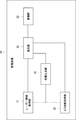
- the monitoring device 20 includes a radar information acquisition unit 21, an AIS information acquisition unit 22, an imaging unit 23, an estimation unit 24, and an information generation unit 25.
- the radar information acquisition unit 21 and the AIS information acquisition unit 22 correspond to the position information acquisition unit 11 in FIG.
- the estimation unit 24 corresponds to the estimation unit 12 in FIG.
- the information generation unit 25 corresponds to the information generation unit 13 in FIG.
- Detailed description of the same functions or operations of the monitoring device 20 as those of the monitoring device 10 of FIG. 1 is omitted.
- the monitoring device 20 will be described as a device used for monitoring a ship traveling on the sea.
- the radar information acquisition unit 21 periodically radiates radio waves to a ship traveling in the surveillance area using a radar, and measures the position of the ship using reflected waves of the radiated radio waves.
- the AIS information acquisition unit 22 regularly receives the AIS information from the ship equipped with the AIS.
- the AIS information includes ship position information.
- the monitoring device 20 identifies the position of the ship equipped with the AIS using the position information included in the AIS information.
- the monitoring device 20 identifies the position of a ship that does not have an AIS, using information obtained using radar (hereinafter referred to as radar information).
- the monitoring device 20 may also specify the position of the ship equipped with the AIS using the radar information.
- the image capturing unit 23 may be a camera that captures a surveillance area on the sea.
- the imaging unit 23 may use a plurality of cameras to capture an image of the surveillance area on the sea, or may use a single camera to capture an image of the surveillance area on the sea.
- the imaging unit 23 outputs the image data obtained by shooting to the estimation unit 24.
- the estimation unit 24 estimates the position of the ship included in the image data. Specifically, the estimation unit 24 converts the image coordinates or camera coordinates of the ship into world coordinates. Further, the estimation unit 24 estimates or specifies whether or not the ships included in the images captured at different timings are the same ship. The images captured at different timings may be different frame images, for example.
- the estimating unit 24 may track the ship using, for example, a particle filter.
- the vessel being tracked may overlap with other vessels or obstacles and may not be included in the frame image.
- the estimation unit 24 may estimate the position of the tracked ship in the frame image by using a particle filter.
- the estimation unit 24 outputs the world coordinates of the ship included in the image data, that is, information about the latitude and longitude of the ship to the information generation unit 25. Further, the estimation unit 24 may output information about the latitude and longitude of the ship estimated using the particle filter to the information generation unit 25.
- the information generation unit 25 receives the position information of the vessel equipped with the AIS from the AIS information acquisition unit 22.
- the information generation unit 25 combines the position information received from the AIS information acquisition unit 22 and the position information received from the estimation unit 24 to generate the trajectory information of the ship.
- the trajectory information may be information indicating the trajectory of the same ship by connecting points indicating two pieces of position information on the GUI with the same line segment.
- the trajectory information may be information stored by associating two pieces of position information with the same ship ID.
- the information generation unit 25 needs to combine the position information of the same ship with the position information received from the AIS information acquisition unit 22 and the position information received from the estimation unit 24.
- the information generation unit 25 is estimated using the position information received from the AIS information acquisition unit 22 and the image data captured at the same timing as the position information received from the AIS information acquisition unit 22 is measured. You may compare with position information.
- the information generation unit 25 may specify or estimate the same ship if these pieces of position information match or if the pieces of position information have a difference within a predetermined range.
- the difference in the position information within a predetermined range is intended to be a difference that can be regarded as an error.
- the estimation unit 24 or the information generation unit 25 may analyze the image data indicating the image captured by the image capturing unit 23 and specify the ship name of the ship included in the image data.
- the estimation unit 24 or the information generation unit 25 may specify the part using, for example, a database that manages the ship name of the ship. You may estimate the ship name of the ship by extracting the ship including the created characters and the like.
- the database may manage ship names of ships that may travel in the monitoring area.
- the information generation unit 25 estimates the position information of the ship included in the AIS information and the image data.
- the ship name and the ship type may be specified using the image data captured by using the ship name reading camera installed at the entrance of the port. Furthermore, the position information of the ship estimated from the image taken using the ship name reading camera and the time information when the image was taken are used for tracking the ship together with the ship name and ship type of the specified ship. It may be displayed on the image taken by the wide area surveillance camera.
- the information generation unit 25 is estimated using the position information received from the AIS information acquisition unit 22 and the image data captured at the same timing as the timing when the position information received from the AIS information acquisition unit 22 was measured.
- the difference from the position information may be used as the correction information.
- the information generation unit 25 may correct or correct the position information received from the estimation unit 24 using the difference between these position information. In other words, the information generator 25 may use the difference between the position information as the offset value.
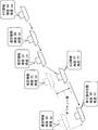
- FIG. 3A shows the trajectory information generated by the information generator 25. It is assumed that the information generation unit 25 has acquired, from the AIS information acquisition unit 22, position information regarding the latitude AA and the longitude aa and position information regarding the latitude DD and the longitude dd for a certain vessel. That is, this ship is moving from latitude AA and longitude aa to latitude DD and longitude dd.
- the information generation unit 25 complements the position information received from the estimation unit 24 as a route or locus between the timing when the latitude AA and the longitude aa are measured and the timing when the latitude DD and the longitude dd are measured. That is, the information generating unit 25 uses the latitude BB and the longitude bb, and further the latitude CC and the longitude as position information between the timing when the latitude AA and the longitude aa are measured and the timing when the latitude DD and the longitude dd are measured.
- the position information with cc is complemented.
- FIG. 3A shows a screen image output to a display unit such as a display. For example, as shown in FIG. 3A, the latitude and longitude of the ship may be displayed at the location of the balloon of the ship.
- the position information estimated using the image data captured at the same timing as the position information of the latitude FF and the longitude ff included in the AIS information is the latitude EE and the longitude ee.
- the ship indicated by the broken line is the position of the ship estimated using the image data.
- the difference between the position of latitude FF and longitude ff and the position of latitude EE and longitude ee may be used as the correction information or offset value.
- the vessel indicated by the broken line may not be displayed, but the vessel at the position of latitude FF and longitude ff may be displayed.
- the position of the estimated latitude GG and the longitude gg is calculated using the offset value as shown in FIG. 3B.
- Latitude HH and longitude hh The display unit such as a display may not display the vessel at the position of latitude GG and longitude gg, but may display the vessel at the position of corrected latitude HH and longitude hh.
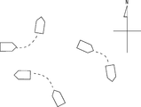
- the object shown by the pentagon indicates a ship mapped on the map using the position information received from the AIS information acquisition unit 22.
- the dotted line between the ships indicates the locus between the position information received from the AIS information acquisition unit 22.
- This dotted line indicates the position information received from the estimation unit 24.
- the information generation unit 25 may display the position information received from the AIS information acquisition unit 22 by using the object indicating the ship and the position information received from the estimation unit 24 by using the dotted line. ..
- the information generation unit 25 outputs the image data shown in FIG. 3A, FIG. 3B, or FIG. 4 to a display unit such as a display.
- a display unit such as a display.
- FIGS. 3A and 3B show that the position information identified by using the AIS information and the position information estimated by the estimation unit 24 are displayed on the image captured by the image capturing unit 23.
- FIG. 4 shows that the position information specified by using the AIS information and the position information estimated by the estimation unit 24 are displayed on the map image.
- FIG. 4 may be referred to as an AIS screen, for example.
- 3A, 3B, and 4 show diagrams generated by the information generation unit 25 using the position information received from the AIS information acquisition unit 22, but the position information received from the radar information acquisition unit 21 is used. May be. That is, the information generation unit 25 may specify the position of the ship not equipped with AIS using the position information received from the radar information acquisition unit 21, and generate the image data of FIG. 3A, FIG. 3B, or FIG. .. FIG. 4 in which the position information specified using the radar information is shown may be referred to as a radar screen.
- the image capturing unit 23 captures an image of the monitoring area including the tracking target ship (S11).
- the estimation unit 24 estimates the position of the tracking target ship included in the captured image (S12).
- the estimation unit 24 may convert the image coordinates of the ship into world coordinates by using a conversion table of predetermined image coordinates and world coordinates.
- the information generation unit 25 determines whether or not the AIS information regarding the same ship as the ship whose position is estimated in step S12 is acquired (S13).
- the AIS information includes ship position information.
- the information generation unit 25 determines that the ships whose position information included in the AIS information matches the position estimated by the estimation unit 12 or the difference between the positions is within a predetermined range as the same ship. You may regard it.
- the information generation unit 25 may regard them as the same ship.
- the ship name of the ship displayed in the image data may be specified by image analysis processing or the like.
- the information generation unit 25 determines that the AIS information regarding the same ship as the position of which is estimated in step S12 is acquired, the position information included in the AIS information and the position estimated in step S12 (hereinafter, estimated position).
- the correction information indicating the difference between the above and the above is generated (S14).
- the correction information may be paraphrased as an offset value.
- the information generation unit 25 determines in step S13 that the AIS information regarding the same ship as the position is estimated is not acquired, the information generation unit 25 acquires radar information about the same ship as the position is estimated. It is determined whether or not (S16).
- the radar information includes the position information of the ship.
- the information generation unit 25 determines that the radar information regarding the same ship as the position of which is estimated is acquired, the information generation unit 25 generates the correction information indicating the difference between the position information included in the radar information and the estimated position (S14). ..
- the information generation unit 25 outputs the position information included in the AIS information to the display unit to display the position information (S15).
- step S16 when the information generation unit 25 determines that the radar information regarding the same ship as the position of which is estimated is not acquired, the difference between the position information included in the AIS information or the radar information and the estimated position. It is determined whether there is correction information indicating (S17).
- the case where the correction information is present is the case where the correction information was generated at the timing when the position information included in the AIS information or the radar information was previously acquired.
- the information generation unit 25 outputs the estimated position corrected using the correction information to the display unit and displays the corrected estimated position information (S18).
- the correction using the correction information may be, for example, moving the latitude and longitude of the estimated position by adding or subtracting the correction information to the estimated position.
- the information generation unit 25 outputs the estimated position to the display unit and displays the estimated position (S19).
- the case where the tracking target ship disappears from the captured image may be, for example, the case where the tracking target ship overlaps with another ship and is hidden behind the other ship or an obstacle. That is, the case where the tracking target ship disappears from the captured image may be the case where occlusion occurs.
- the estimation unit 24 recognizes that the tracking target ship disappears from the captured image (S21). For example, the estimation unit 24 may recognize that the tracking target ship has disappeared when the ship being tracked using the particle filter is not displayed in the captured image.
- the substantially same timing includes a difference between a timing at which an image of a tracking target ship disappearing and a predetermined period. That is, the substantially same timing includes a timing shift that can be regarded as an error.
- the information generation unit 25 determines that the AIS information or the radar information having the position information of the tracking target ship is held at substantially the same timing as the timing at which the image of the disappearing tracking target ship is captured. In this case, the process of step S23 is executed.
- step S23 the information generation unit 25 generates particles used for tracking the ship based on the position information included in the AIS information or the radar information (S23). Generating particles may be rephrased as scattering particles.
- the information generation unit 25 must not hold the AIS information or the radar information having the position information of the tracking target ship at substantially the same timing as the timing at which the image of the tracking target ship disappearing is captured. If determined, the process of step S24 is executed.
- step S24 the information generation unit 25 generates particles used for tracking the ship based on the trajectory of the tracking target ship so far (S24).
- step S23 particles are generated based on the known ship position information. Therefore, the distribution of particles generated in step S23 is in a narrower range than the distribution of particles generated in step S24 in which position information does not exist.
- step S24 since the position information of the ship does not exist, the area in which the ship may exist becomes wider than the area in which the position information of the ship exists in step S23. That is, the tracking accuracy of the ship using the particles generated in step S23 is higher than the tracking accuracy of the ship using the particles generated in step S24. In other words, when the tracking target ship disappears from the captured image, the particle dispersion area can be narrowed by using the position information included in the AIS information or the radar information regarding the tracking target ship.
- the monitoring device 20 calculates the trajectory of a ship by combining the position information of the ship obtained from the AIS or the radar with the position information of the ship estimated from the captured image. It can be displayed more accurately.
- the monitoring device 20 can generate correction information for correcting the position of the ship estimated from the image by using the AIS information or the radar information acquired at the timing substantially the same as the timing at which the image is captured. it can. Specifically, the monitoring device 20 sets the difference between the position of the ship estimated from the image and the position included in the AIS information or the radar information as the offset value. The monitoring device 20 corrects the position of the ship estimated from the image using the offset value. Accordingly, the monitoring device 20 can improve the accuracy of the estimated position used as the position of the tracking target at the timing when the position information of the tracking target cannot be acquired using the AIS information or the radar information.
- FIG. 7 is a block diagram showing a configuration example of the monitoring devices 10 and 20 (hereinafter referred to as the monitoring device 10 and the like).
- the monitoring device 10 and the like include a network interface 1201, a processor 1202, and a memory 1203.
- the network interface 1201 is used to communicate with other network node devices that make up the communication system.
- the network interface 1201 may be used to perform wireless communication.
- the network interface 1201 may be used to perform wireless LAN communication defined in IEEE 802.11 series or mobile communication defined in 3GPP (3rd Generation Partnership Project).
- the network interface 1201 may include, for example, a network interface card (NIC) compliant with IEEE802.3 series.
- NIC network interface card
- the processor 1202 reads the software (computer program) from the memory 1203 and executes the software to perform the processing of the monitoring device 10 and the like described using the flowcharts or sequences in the above-described embodiment.
- the processor 1202 may be, for example, a microprocessor, MPU (Micro Processing Unit), or CPU (Central Processing Unit).
- the processor 1202 may include multiple processors.
- the memory 1203 is composed of a combination of a volatile memory and a non-volatile memory.
- Memory 1203 may include storage located remotely from processor 1202. In this case, the processor 1202 may access the memory 1203 via an I/O interface (not shown).
- the memory 1203 is used to store a software module group.
- the processor 1202 can perform the processing of the monitoring device 10 and the like described in the above embodiment by reading these software modules from the memory 1203 and executing them.
- each of the processors included in the monitoring device 10 and the like executes one or a plurality of programs including a group of instructions for causing a computer to execute the algorithm described with reference to the drawing.
- Non-transitory computer-readable media include various types of tangible storage media.
- Examples of the non-transitory computer-readable medium include a magnetic recording medium, a magneto-optical recording medium (for example, a magneto-optical disk), a CD-ROM (Read Only Memory), a CD-R, a CD-R/W, and a semiconductor memory.
- the magnetic recording medium may be, for example, a flexible disk, a magnetic tape, or a hard disk drive.
- the semiconductor memory may be, for example, a mask ROM, a PROM (Programmable ROM), an EPROM (Erasable PROM), a flash ROM, or a RAM (Random Access Memory).
- the program may be supplied to the computer by various types of transitory computer readable media. Examples of transitory computer-readable media include electrical signals, optical signals, and electromagnetic waves.
- the transitory computer-readable medium can supply the program to the computer via a wired communication path such as an electric wire and an optical fiber, or a wireless communication path.
- a position information acquisition unit that acquires position information of the tracking target
- An estimation unit that estimates the position of the tracking target displayed in an image obtained by capturing a predetermined area, The position of the tracking target between the position indicated by the position information acquired at the first timing and the position indicated by the position information acquired at the second timing later than the first timing is estimated.
- An information generating unit that complements the position of the tracking target to generate the trajectory information of the tracking target.
- Appendix 2 The position information acquisition unit, The monitoring device according to appendix 1, which acquires the position information of the tracking target included in the AIS information received from the tracking target equipped with an AIS.
- the position information acquisition unit The monitoring device according to appendix 1 or 2, wherein the position information of the tracking target is periodically acquired using a radar.
- the information generation unit Note 1 to correct the estimated position of the tracking target by using the difference between the position of the tracking target indicated by the position information and the position of the tracking target estimated at the timing when the position information is acquired.
- the monitoring device according to any one of 3 above.
- the estimation unit is 5.
- the estimation unit is The monitoring device according to appendix 5, wherein when the tracking target is not displayed in an image for a predetermined period of time, the area estimated as the position of the tracking target is limited using the position information of the tracking target.
- the estimation unit is 7.
- the information generation unit 8.
- the information generation unit The monitoring device according to appendix 2, wherein the trajectory information is displayed on an AIS screen generated based on the AIS information.
- (Appendix 12) Acquire the location information of the tracking target, Estimate the position of the tracking target displayed in the image captured in a predetermined area, The position of the tracking target between the position indicated by the position information acquired at the first timing and the position indicated by the position information acquired at the second timing later than the first timing is estimated.
- a non-transitory computer-readable medium that stores a program that causes a computer to perform complementary generation using the position of the tracking target to generate the trajectory information of the tracking target.
Abstract
船舶の追跡精度を向上させることができる監視装置を提供することを目的とする。本開示にかかる監視装置(10)は、追跡対象の位置情報を取得する位置情報取得部(11)と、所定の領域を撮影した画像に表示される追跡対象の位置を推定する推定部(12)と、第1のタイミングに取得された位置情報が示す位置と、第1のタイミングよりも遅い第2のタイミングに取得された位置情報が示す位置との間の追跡対象の位置を、推定された追跡対象の位置を用いて補完して追跡対象の軌跡情報を生成する情報生成部(13)と、を備える。
Description
本開示は、監視装置、追跡方法、及びプログラムに関する。
海上における安全な航行を実現するために、海上を航行する船舶を監視する監視システムが用いられている。監視システムを用いて特定された船舶の位置情報は、それぞれの船舶に送信され、船舶の衝突を未然に防ぐことが期待されている。
特許文献1には、船舶の位置を、レーダーを用いて認識することが記載されている。また、船舶の位置を認識する手段として、船舶にAIS(Automatic Identification System)を搭載させ、監視システムがAIS情報を収集することによって、船舶の位置を認識することも一般的に行われている。AIS情報には、船舶の船名、目的地、現在位置等の情報が含まれている。
レーダーを用いた船舶の位置の特定は、周期的に行われる。また、AIS情報も船舶から監視システムへ周期的に送信されるため、AIS情報を用いた船舶の位置の特定も周期的に行われる。しかし、周期的にしか船舶の位置を特定することができない場合、あるタイミングに船舶の位置を特定してから、次のタイミングに船舶の位置を特定するまでの間に船舶がどのような経路を移動したかを認識することができない。そのため、監視システムは、レーダーもしくはAIS情報を用いて収集した位置情報を用いて船舶を追跡する場合、正確に船舶を追跡することができないという問題がある。
本開示の目的は、船舶の追跡精度を向上させることができる監視装置、追跡方法、及びプログラムを提供することにある。
本開示の第1の態様にかかる監視装置は、追跡対象の位置情報を取得する位置情報取得部と、所定の領域を撮影した画像に表示される前記追跡対象の位置を推定する推定部と、第1のタイミングに取得された位置情報が示す位置と、前記第1のタイミングよりも遅い第2のタイミングに取得された位置情報が示す位置との間の前記追跡対象の位置を、推定された前記追跡対象の位置を用いて補完して前記追跡対象の軌跡情報を生成する情報生成部と、を備える。
本開示の第2の態様にかかる追跡方法は、追跡対象の位置情報を取得し、所定の領域を撮影した画像に表示される前記追跡対象の位置を推定し、第1のタイミングに取得された位置情報が示す位置と、前記第1のタイミングよりも遅い第2のタイミングに取得された位置情報が示す位置との間の前記追跡対象の位置を、推定された前記追跡対象の位置を用いて補完して前記追跡対象の軌跡情報を生成する。
本開示の第3の態様にかかるプログラムは、追跡対象の位置情報を取得し、所定の領域を撮影した画像に表示される前記追跡対象の位置を推定し、第1のタイミングに取得された位置情報が示す位置と、前記第1のタイミングよりも遅い第2のタイミングに取得された位置情報が示す位置との間の前記追跡対象の位置を、推定された前記追跡対象の位置を用いて補完して前記追跡対象の軌跡情報を生成することをコンピュータに実行させる。
本開示により、船舶の追跡精度を向上させることができる監視装置、追跡方法、及びプログラムを提供することができる。
(実施の形態1)
以下、図面を参照して本開示の実施の形態について説明する。図1を用いて実施の形態1にかかる監視装置10の構成例について説明する。監視装置10は、プロセッサがメモリに格納されたプログラムを実行することによって動作するコンピュータ装置であってもよい。監視装置10は、例えば、サーバ装置であってもよい。
以下、図面を参照して本開示の実施の形態について説明する。図1を用いて実施の形態1にかかる監視装置10の構成例について説明する。監視装置10は、プロセッサがメモリに格納されたプログラムを実行することによって動作するコンピュータ装置であってもよい。監視装置10は、例えば、サーバ装置であってもよい。
監視装置10は、位置情報取得部11、推定部12、及び情報生成部13を有している。位置情報取得部11、推定部12、及び情報生成部13等の監視装置10の構成要素は、プロセッサがメモリに格納されたプログラムを実行することによって処理が実行されるソフトウェアもしくはモジュールであってもよい。または、監視装置10の構成要素は、回路もしくはチップ等のハードウェアであってもよい。
位置情報取得部11は、追跡対象の位置情報を取得する。追跡対象は、船舶、車両、航空機等の移動手段であってもよく、人もしくは動物等であってもよい。位置情報は、例えば、追跡対象がGPS(Global Positioning System)等を用いて測定した位置情報であってもよい。例えば、位置情報取得部11は、AISを搭載している船舶から、位置情報を含むAIS情報を受信してもよい。もしくは、位置情報取得部11は、レーダーを用いて追跡対象へ電波を照射し、追跡対象の位置を測定してもよい。位置情報取得部11は、定期的もしくは周期的に追跡対象の位置情報を取得してもよく、任意のタイミングに追跡対象の位置情報を取得してもよい。
AIS情報に含まれる位置情報は、船舶に搭載されたGPS等により取得された位置情報であり、GPS等がその位置情報を取得した時刻情報を含む。
推定部12は、所定の領域を撮影した画像に表示される追跡対象の位置を推定する。所定の領域は、監視装置10が監視する領域であり、例えば、海上の一部の領域であってもよく、街中の一部の領域等であってもよい。推定部12は、例えば、カメラを用いて所定の領域を撮影する。カメラを用いて生成する画像は、静止画であってもよく、動画であってもよい。画像に表示される追跡対象の位置を推定するとは、例えば、画像に表示される追跡対象の画像座標もしくはカメラ座標を、世界座標へ変換することであってもよい。画像座標もしくはカメラ座標は、例えば、画素の位置を用いて示されてもよい。世界座標は、例えば、緯度及び経度を用いて示されてもよい。推定部12は、例えば、画像座標もしくはカメラ座標と、世界座標との対応を示すテーブル情報を保持していてもよい。
情報生成部13は、第1のタイミングに取得された位置情報が示す位置と、第1のタイミングよりも遅い第2のタイミングに取得された位置情報が示す位置との間の追跡対象の位置を、推定された追跡対象の位置を用いて補完する。情報生成部13は、異なるタイミングに取得された追跡対象の位置情報と、画像から推定した追跡対象の位置情報を用いて、追跡対象の軌跡情報を生成する。軌跡情報は、ディスプレイにおいて線分等を用いて示される情報であってもよく、船舶毎に、各時刻における位置を示す情報であってもよい。
第2のタイミングは、第1のタイミングから所定の期間経過した後のタイミングである。所定の期間は、例えば、数秒もしくは数分等であってもよく、位置情報を取得するシステム等によって定められてもよい。情報生成部13は、第1のタイミングと第2のタイミングとの間において撮影された画像から推定された追跡対象の位置と、第1のタイミング及び第2のタイミングにおける追跡対象の位置とを組み合わせる。
以上説明したように、監視装置10は、AISもしくはレーダー等を用いて追跡対象の位置情報を取得することができないタイミングにおける追跡対象の位置を、追跡対象を撮影した画像から推定する。監視装置10を用いることによって、追跡対象に関する位置情報を特定することができない期間を減少させることができるため、追跡精度を向上させることができる。
(実施の形態2)
続いて、図2を用いて実施の形態2にかかる監視装置20の構成例について説明する。監視装置20は、レーダー情報取得部21、AIS情報取得部22、撮像部23、推定部24、及び情報生成部25を有している。レーダー情報取得部21及びAIS情報取得部22は、図1の位置情報取得部11に相当する。推定部24は、図1の推定部12に相当する。情報生成部25は、図1の情報生成部13に相当する。監視装置20において、図1の監視装置10と同様の機能もしくは動作については詳細な説明を省略する。実施の形態2においては、監視装置20を、海上を航行する船舶を監視するために用いられる装置として説明する。
続いて、図2を用いて実施の形態2にかかる監視装置20の構成例について説明する。監視装置20は、レーダー情報取得部21、AIS情報取得部22、撮像部23、推定部24、及び情報生成部25を有している。レーダー情報取得部21及びAIS情報取得部22は、図1の位置情報取得部11に相当する。推定部24は、図1の推定部12に相当する。情報生成部25は、図1の情報生成部13に相当する。監視装置20において、図1の監視装置10と同様の機能もしくは動作については詳細な説明を省略する。実施の形態2においては、監視装置20を、海上を航行する船舶を監視するために用いられる装置として説明する。
レーダー情報取得部21は、監視領域を航行する船舶に対してレーダーを用いて周期的に電波を照射し、照射した電波の反射波を用いて、船舶の位置を測定する。一方、AIS情報取得部22は、AISを搭載している船舶から定期的にAIS情報を受信する。AIS情報には、船舶の位置情報が含まれる。監視装置20は、AISを搭載している船舶の位置を、AIS情報に含まれる位置情報を用いて特定する。また、監視装置20は、AISを搭載していない船舶の位置を、レーダーを用いて得られる情報(以下、レーダー情報とする)を用いて特定する。監視装置20は、AISを搭載している船舶の位置についても、レーダー情報を用いて特定してもよい。
撮像部23は、海上の監視領域を撮影するカメラであってもよい。撮像部23は、複数のカメラを用いて、海上の監視領域を撮影してもよく、1台のカメラを用いて海上の監視領域を撮影してもよい。撮像部23は、撮影して得られた画像データを推定部24へ出力する。
推定部24は、画像データに含まれる船舶の位置を推定する。具体的には、推定部24は、船舶の画像座標もしくはカメラ座標を、世界座標へ変換する。また、推定部24は、異なるタイミングに撮影された画像に含まれる船舶が、同一の船舶であるか否かを推定もしくは特定する。異なるタイミングに撮影された画像は、例えば、異なるフレーム画像であってもよい。
推定部24は、例えば、パーティクルフィルタを用いて、船舶を追跡してもよい。追跡していた船舶が、他の船舶もしくは障害物等と重なり、フレーム画像に含まれなくなる場合がある。このような場合、推定部24は、パーティクルフィルタを用いて、追跡していた船舶のフレーム画像内における位置を推定してもよい。推定部24は、画像データに含まれる船舶の世界座標、つまり、船舶の緯度及び経度に関する情報を情報生成部25へ出力する。さらに、推定部24は、パーティクルフィルタを用いて推定された船舶の緯度及び経度に関する情報を情報生成部25へ出力してもよい。
情報生成部25は、AISを搭載している船舶の位置情報をAIS情報取得部22から受け取る。情報生成部25は、AIS情報取得部22から受け取った位置情報と、推定部24から受け取った位置情報とを組み合わせて船舶の軌跡情報を生成する。軌跡情報は、GUI上に、2つの位置情報を示す点を同じ線分で結ぶことによって、同一の船舶の軌跡を示す情報であってもよい。もしくは、軌跡情報は、2つの位置情報を同一の船舶IDに対応付けて記憶される情報であってもよい。情報生成部25は、AIS情報取得部22から受け取った位置情報と、推定部24から受け取った位置情報とについて、同一の船舶の位置情報を組み合わせる必要がある。例えば、情報生成部25は、AIS情報取得部22から受け取った位置情報と、AIS情報取得部22から受け取った位置情報が測定されたタイミングと同じタイミングに撮影された画像データを用いて推定された位置情報とを比較してもよい。情報生成部25は、これらの位置情報が一致する場合、もしくは、これらの位置情報が予め定められた範囲内の差である場合、同一の船舶と特定もしくは推定してもよい。これらの位置情報が予め定められた範囲内の差とは、位置情報の差が誤差とみなせる程度の差であることを意図している。
または、推定部24もしくは情報生成部25は、撮像部23が撮影した画像を示す画像データを解析し、画像データ内に含まれる船舶の船名を特定してもよい。推定部24もしくは情報生成部25は、画像データ内に含まれる船舶の船名の一部を特定することができない場合、例えば、船舶の船名を管理するデータベース等を用いて、特定することができた文字等を含む船舶を抽出し、船舶の船名を推定してもよい。データベースには、監視領域を航行する可能性のある船舶の船名が管理されていてもよい。情報生成部25は、画像データを用いて特定した船名と、AIS情報に含まれる船舶の船名とが一致した場合、AIS情報に含まれる船舶の位置情報と、画像データを用いて推定された位置情報とを組み合わせてもよい。具体的には、港湾の出入り口に設置された船名読取カメラを用いて撮影された画像データを用いて、船名及び船種が特定されてもよい。さらに、船名読取カメラを用いて撮影された画像から推定される船舶の位置情報、及び、画像を撮影した時刻情報は、特定された船舶の船名及び船種とともに、船舶の追跡に用いられる広域監視カメラにおいて撮影された画像に、表示されてもよい。
また、情報生成部25は、AIS情報取得部22から受け取った位置情報と、AIS情報取得部22から受け取った位置情報が測定されたタイミングと同じタイミングに撮影された画像データを用いて推定された位置情報との差を、補正情報として用いてもよい。情報生成部25は、これらの位置情報の差を用いて、推定部24から受け取った位置情報を修正もしくは補正してもよい。言い換えると、情報生成部25は、位置情報の差をオフセット値として用いてもよい。
ここで、図3Aを用いて情報生成部25が生成する軌跡情報について説明する。図3Aは、情報生成部25において生成された軌跡情報を示している。情報生成部25は、AIS情報取得部22から、ある船舶について、緯度AA及び経度aaとの位置情報と、緯度DD及び経度ddとの位置情報を取得したとする。つまり、この船舶は、緯度AA及び経度aaから、緯度DD及び経度ddへ移動している。
情報生成部25は、緯度AA及び経度aaが測定されたタイミングと、緯度DD及び経度ddが測定されたタイミングとの間の経路もしくは軌跡として、推定部24から受け取った位置情報を補完する。つまり、情報生成部25は、緯度AA及び経度aaが測定されたタイミングと、緯度DD及び経度ddが測定されたタイミングとの間の位置情報として、緯度BB及び経度bb、さらに、緯度CC及び経度ccとの位置情報を補完する。図3Aは、ディスプレイ等の表示部へ出力される画面イメージを示している。例えば、図3Aに示されるように、船舶の吹き出しの箇所に、船舶の緯度及び経度が表示されてもよい。
また、図3Bは、AIS情報に含まれる緯度FF及び経度ffの位置情報が測定されたタイミングと同じタイミングに撮影された画像データを用いて推定された位置情報が緯度EE及び経度eeであることを示している。破線で示される船舶が、画像データを用いて推定された船舶の位置である。この場合、緯度FF及び経度ffの位置と緯度EE及び経度eeの位置との差が、補正情報もしくはオフセット値として用いられてもよい。ディスプレイ等の表示部には、破線で示される船舶は表示されず、緯度FF及び経度ffの位置の船舶が表示されてもよい。その後、画像データを用いて船舶の位置が緯度GG及び経度ggであることが推定された場合、オフセット値を用いて、図3Bに示されるように、推定された緯度GG及び経度ggの位置が、緯度HH及び経度hhへ修正されてもよい。ディスプレイ等の表示部へは、緯度GG及び経度ggの位置の船舶は表示されず、修正後の緯度HH及び経度hhの位置の船舶が表示されてもよい。
また、図4を用いて、図3A及びBとは異なる軌跡情報について説明する。5角形にて示されている物体は、AIS情報取得部22から受け取った位置情報を用いて地図にマッピングされた船舶を示している。船舶と船舶との間の点線は、AIS情報取得部22から受け取った位置情報の間の軌跡を示している。この点線は、推定部24から受け取った位置情報を示している。このように、情報生成部25は、AIS情報取得部22から受け取った位置情報を、船舶を示す物体を用いて表示し、推定部24から受け取った位置情報を、点線を用いて示してもよい。
情報生成部25は、図3A、図3B、もしくは図4に示す画像データをディスプレイ等の表示部へ出力する。例えば、図3A及びBは、撮像部23において撮影された画像に、AIS情報を用いて特定された位置情報と、推定部24において推定された位置情報を表示させたことを示している。図4は、地図画像に、AIS情報を用いて特定された位置情報と、推定部24において推定された位置情報を表示させたことを示している。図4は、例えば、AIS画面と称されてもよい。
図3A、図3B及び図4は、情報生成部25がAIS情報取得部22から受け取った位置情報を用いて生成した図を示しているが、レーダー情報取得部21から受け取った位置情報が用いられてもよい。つまり、情報生成部25は、AISを非搭載の船舶の位置をレーダー情報取得部21から受け取った位置情報を用いて特定し、図3A、図3Bもしくは図4の画像データを生成してもよい。レーダー情報を用いて特定された位置情報が示された図4は、レーダー画面と称されてもよい。
続いて、図5を用いて実施の形態2にかかる軌跡情報の生成処理の流れについて説明する。はじめに、撮像部23は、追跡対象の船舶を含む監視領域を撮影する(S11)。次に、推定部24は、撮影された画像に含まれる追跡対象の船舶の位置を推定する(S12)。例えば、推定部24は、予め定められた画像座標と世界座標との変換表を用いて、船舶の画像座標を世界座標へ変換してもよい。
次に、情報生成部25は、ステップS12において位置が推定された船舶と同一の船舶に関するAIS情報を取得したか否かを判定する(S13)。AIS情報には船舶の位置情報が含まれる。情報生成部25は、AIS情報に含まれる位置情報が推定部12において推定された位置と一致する、もしくは、それぞれの位置の差が、予め定められた範囲内である船舶を、同一の船舶とみなしてもよい。もしくは、情報生成部25は、AIS情報に含まれる船舶の船名と、画像データに表示される船舶の船名とが同一である場合、同一の船舶とみなしてもよい。画像データに表示される船舶の船名は、画像解析処理等によって特定されてもよい。
情報生成部25は、ステップS12において位置が推定された船舶と同一の船舶に関するAIS情報を取得したと判定した場合、AIS情報に含まれる位置情報とステップS12において推定された位置(以下、推定位置とする)との差を示す補正情報を生成する(S14)。補正情報は、オフセット値と言い換えられてもよい。
また、情報生成部25は、ステップS13において、位置が推定された船舶と同一の船舶に関するAIS情報を取得していないと判定した場合、位置が推定された船舶と同一の船舶に関するレーダー情報を取得したか否かを判定する(S16)。レーダー情報には船舶の位置情報が含まれる。情報生成部25は、位置が推定された船舶と同一の船舶に関するレーダー情報を取得したと判定した場合、レーダー情報に含まれる位置情報と推定位置との差を示す補正情報を生成する(S14)。
ステップS14の次に、情報生成部25は、AIS情報に含まれる位置情報を表示部へ出力し、位置情報を表示させる(S15)。
ステップS16において、情報生成部25は、位置が推定された船舶と同一の船舶に関するレーダー情報を取得していないと判定した場合、AIS情報もしくはレーダー情報に含まれる位置情報と、推定位置との差を示す補正情報があるかを判定する(S17)。補正情報がある場合とは、以前に、AIS情報もしくはレーダー情報に含まれる位置情報を取得したタイミングに補正情報が生成された場合である。
情報生成部25は、補正情報があると判定した場合、補正情報を用いて修正した推定位置を表示部へ出力し、修正した推定位置情報を表示させる(S18)。補正情報を用いた修正は、例えば、推定位置に補正情報を加算もしくは減算して推定位置の緯度及び経度を移動させることであってもよい。情報生成部25は、補正情報がないと判定した場合、推定位置を表示部へ出力し、推定位置を表示させる(S19)。
続いて、図6を用いて、撮影画像から追跡対象の船舶が消失した場合の処理の流れについて説明する。撮影画像から追跡対象の船舶が消失した場合とは、例えば、追跡対象の船舶が他の船舶と重なり、他の船舶もしくは障害物等の後ろに隠れてしまった場合等がある。つまり、撮影画像から追跡対象の船舶が消失した場合とは、オクルージョンが発生した場合であってもよい。
はじめに、推定部24は、撮影画像から追跡対象の船舶が消失したことを認識する(S21)。例えば、推定部24は、パーティクルフィルタを用いて追跡していた船舶が、撮影画像に表示されない場合に、追跡対象の船舶が消失したと認識してもよい。
次に、情報生成部25は、追跡対象の船舶が消失している画像を撮影したタイミングと実質的に同一のタイミングの追跡対象の船舶の位置情報を有するAIS情報もしくはレーダー情報を保持しているか否かを判定する(S22)。実質的に同一のタイミングとは、追跡対象の船舶が消失している画像を撮影したタイミングと、所定期間の差を含む。つまり、実質的に同一のタイミングとは、誤差とみなせる程度のタイミングのずれを含む。
情報生成部25は、追跡対象の船舶が消失している画像を撮影したタイミングと実質的に同一のタイミングの追跡対象の船舶の位置情報を有するAIS情報もしくはレーダー情報を保持していると判定した場合、ステップS23の処理を実行する。
ステップS23においては、情報生成部25は、AIS情報もしくはレーダー情報に含まれる位置情報に基づいて、船舶の追跡に用いるパーティクルを生成する(S23)。パーティクルを生成するとは、パーティクルを散布すると言い換えられてもよい。
一方、情報生成部25は、追跡対象の船舶が消失している画像を撮影したタイミングと実質的に同一のタイミングの追跡対象の船舶の位置情報を有するAIS情報もしくはレーダー情報を保持していないと判定した場合、ステップS24の処理を実行する。
ステップS24においては、情報生成部25は、これまでの追跡対象の船舶の軌跡に基づいて、船舶の追跡に用いるパーティクルを生成する(S24)。
ステップS23においては、判明している船舶の位置情報に基づいてパーティクルが生成される。そのため、ステップS23において生成されるパーティクルの分布は、位置情報が存在しないステップS24において生成されるパーティクルの分布よりも狭い範囲となる。ステップS24においては、船舶の位置情報が存在しないことから、船舶の存在する可能性があるエリアが、ステップS23における船舶の位置情報が存在する場合と比較して広くなる。つまり、ステップS23において生成されたパーティクルを用いた船舶の追跡精度は、ステップS24において生成されたパーティクルを用いた船舶の追跡精度よりも高くなる。言い換えると、撮影画像から追跡対象の船舶が消失した場合、追跡対象の船舶に関するAIS情報もしくはレーダー情報に含まれる位置情報を用いることによって、パーティクルの散布エリアを狭めることができる。
以上説明したように、実施の形態2にかかる監視装置20は、AISもしくはレーダー等から得られる船舶の位置情報と、撮影画像から推定される船舶の位置情報とを組み合わせることによって、船舶の軌跡をより正確に表示することができる。
さらに、監視装置20は、画像を撮影したタイミングと実質的に同一のタイミングに取得したAIS情報もしくはレーダー情報とを用いて、画像から推定される船舶の位置を補正する補正情報を生成することができる。具体的には、監視装置20は、画像から推定される船舶の位置と、AIS情報もしくはレーダー情報に含まれる位置との差をオフセット値とする。監視装置20は、画像から推定される船舶の位置を、オフセット値を用いて補正する。これより、監視装置20は、AIS情報もしくはレーダー情報を用いて追跡対象の位置情報を取得することができないタイミングにおける追跡対象の位置として用いられる推定位置の正確性を向上させることができる。
図7は、監視装置10及び20(以下、監視装置10等とする)の構成例を示すブロック図である。図7を参照すると、監視装置10等は、ネットワーク・インターフェース1201、プロセッサ1202、及びメモリ1203を含む。ネットワーク・インターフェース1201は、通信システムを構成する他のネットワークノード装置と通信するために使用される。ネットワーク・インターフェース1201は、無線通信を行うために使用されてもよい。例えば、ネットワーク・インターフェース1201は、IEEE 802.11 seriesにおいて規定された無線LAN通信、もしくは3GPP(3rd Generation Partnership Project)において規定されたモバイル通信を行うために使用されてもよい。もしくは、ネットワーク・インターフェース1201は、例えば、IEEE 802.3 seriesに準拠したネットワークインターフェースカード(NIC)を含んでもよい。
プロセッサ1202は、メモリ1203からソフトウェア(コンピュータプログラム)を読み出して実行することで、上述の実施形態においてフローチャートもしくはシーケンスを用いて説明された監視装置10等の処理を行う。プロセッサ1202は、例えば、マイクロプロセッサ、MPU(Micro Processing Unit)、又はCPU(Central Processing Unit)であってもよい。プロセッサ1202は、複数のプロセッサを含んでもよい。
メモリ1203は、揮発性メモリ及び不揮発性メモリの組み合わせによって構成される。メモリ1203は、プロセッサ1202から離れて配置されたストレージを含んでもよい。この場合、プロセッサ1202は、図示されていないI/Oインタフェースを介してメモリ1203にアクセスしてもよい。
図7の例では、メモリ1203は、ソフトウェアモジュール群を格納するために使用される。プロセッサ1202は、これらのソフトウェアモジュール群をメモリ1203から読み出して実行することで、上述の実施形態において説明された監視装置10等の処理を行うことができる。
図7を用いて説明したように、監視装置10等が有するプロセッサの各々は、図面を用いて説明されたアルゴリズムをコンピュータに行わせるための命令群を含む1又は複数のプログラムを実行する。
上述の例において、プログラムは、様々なタイプの非一時的なコンピュータ可読媒体(non-transitory computer readable medium)を用いて格納され、コンピュータに供給することができる。非一時的なコンピュータ可読媒体は、様々なタイプの実体のある記録媒体(tangible storage medium)を含む。非一時的なコンピュータ可読媒体の例は、磁気記録媒体、光磁気記録媒体(例えば光磁気ディスク)、CD-ROM(Read Only Memory)、CD-R、CD-R/W、半導体メモリを含む。磁気記録媒体は、例えばフレキシブルディスク、磁気テープ、ハードディスクドライブであってもよい。半導体メモリは、例えば、マスクROM、PROM(Programmable ROM)、EPROM(Erasable PROM)、フラッシュROM、RAM(Random Access Memory)であってもよい。また、プログラムは、様々なタイプの一時的なコンピュータ可読媒体(transitory computer readable medium)によってコンピュータに供給されてもよい。一時的なコンピュータ可読媒体の例は、電気信号、光信号、及び電磁波を含む。一時的なコンピュータ可読媒体は、電線及び光ファイバ等の有線通信路、又は無線通信路を介して、プログラムをコンピュータに供給できる。
なお、本開示は上記実施の形態に限られたものではなく、趣旨を逸脱しない範囲で適宜変更することが可能である。また、本開示は、それぞれの実施の形態を適宜組み合わせて実施されてもよい。
上記の実施形態の一部又は全部は、以下の付記のようにも記載されうるが、以下には限られない。
(付記1)
追跡対象の位置情報を取得する位置情報取得部と、
所定の領域を撮影した画像に表示される前記追跡対象の位置を推定する推定部と、
第1のタイミングに取得された位置情報が示す位置と、前記第1のタイミングよりも遅い第2のタイミングに取得された位置情報が示す位置との間の前記追跡対象の位置を、推定された前記追跡対象の位置を用いて補完して前記追跡対象の軌跡情報を生成する情報生成部と、を備える監視装置。
(付記2)
前記位置情報取得部は、
AISを搭載する前記追跡対象から受信したAIS情報に含まれる前記追跡対象の位置情報を取得する、付記1に記載の監視装置。
(付記3)
前記位置情報取得部は、
レーダーを用いて周期的に前記追跡対象の位置情報を取得する、付記1または2に記載の監視装置。
(付記4)
前記情報生成部は、
前記位置情報が示す前記追跡対象の位置と、前記位置情報が取得されたタイミングに推定された前記追跡対象の位置との差を用いて、推定した前記追跡対象の位置を補正する、付記1乃至3のいずれか1項に記載の監視装置。
(付記5)
前記推定部は、
パーティクルフィルタを用いて前記追跡対象の位置を推定する、付記1乃至4のいずれか1項に記載の監視装置。
(付記6)
前記推定部は、
所定の期間、前記追跡対象が画像に表示されない場合、前記追跡対象の位置情報を用いて、前記追跡対象の位置として推定する領域を限定する、付記5に記載の監視装置。
(付記7)
前記推定部は、
前記追跡対象の画像座標を世界座標へ変換して前記追跡対象の位置を推定する、付記1乃至6のいずれか1項に記載の監視装置。
(付記8)
前記情報生成部は、
前記軌跡情報を前記画像に表示させる、付記1乃至7のいずれか1項に記載の監視装置。
(付記9)
前記情報生成部は、
前記軌跡情報を、前記AIS情報に基づいて生成されるAIS画面に表示させる、付記2に記載の監視装置。
(付記10)
前記情報生成部は、
前記軌跡情報を、前記レーダーを用いて取得した情報に基づいて生成されるレーダー画面に表示させる、付記3に記載の監視装置。
(付記11)
追跡対象の位置情報を取得し、
所定の領域を撮影した画像に表示される前記追跡対象の位置を推定し、
第1のタイミングに取得された位置情報が示す位置と、前記第1のタイミングよりも遅い第2のタイミングに取得された位置情報が示す位置との間の前記追跡対象の位置を、推定された前記追跡対象の位置を用いて補完して前記追跡対象の軌跡情報を生成する、監視装置において実行される追跡方法。
(付記12)
追跡対象の位置情報を取得し、
所定の領域を撮影した画像に表示される前記追跡対象の位置を推定し、
第1のタイミングに取得された位置情報が示す位置と、前記第1のタイミングよりも遅い第2のタイミングに取得された位置情報が示す位置との間の前記追跡対象の位置を、推定された前記追跡対象の位置を用いて補完して前記追跡対象の軌跡情報を生成することをコンピュータに実行させるプログラムが格納された非一時的なコンピュータ可読媒体。
10 監視装置
11 位置情報取得部
12 推定部
13 情報生成部
20 監視装置
21 レーダー情報取得部
22 AIS情報取得部
23 撮像部
24 推定部
25 情報生成部
11 位置情報取得部
12 推定部
13 情報生成部
20 監視装置
21 レーダー情報取得部
22 AIS情報取得部
23 撮像部
24 推定部
25 情報生成部
Claims (12)
- 追跡対象の位置情報を取得する位置情報取得部と、
所定の領域を撮影した画像に表示される前記追跡対象の位置を推定する推定部と、
第1のタイミングに取得された位置情報が示す位置と、前記第1のタイミングよりも遅い第2のタイミングに取得された位置情報が示す位置との間の前記追跡対象の位置を、推定された前記追跡対象の位置を用いて補完して前記追跡対象の軌跡情報を生成する情報生成部と、を備える監視装置。 - 前記位置情報取得部は、
AISを搭載する前記追跡対象から受信したAIS情報に含まれる前記追跡対象の位置情報を取得する、請求項1に記載の監視装置。 - 前記位置情報取得部は、
レーダーを用いて周期的に前記追跡対象の位置情報を取得する、請求項1または2に記載の監視装置。 - 前記情報生成部は、
前記位置情報が示す前記追跡対象の位置と、前記位置情報が取得されたタイミングに推定された前記追跡対象の位置との差を用いて、推定した前記追跡対象の位置を補正する、請求項1乃至3のいずれか1項に記載の監視装置。 - 前記推定部は、
パーティクルフィルタを用いて前記追跡対象の位置を推定する、請求項1乃至4のいずれか1項に記載の監視装置。 - 前記推定部は、
所定の期間、前記追跡対象が画像に表示されない場合、前記追跡対象の位置情報を用いて、前記追跡対象の位置として推定する領域を限定する、請求項5に記載の監視装置。 - 前記推定部は、
前記追跡対象の画像座標を世界座標へ変換して前記追跡対象の位置を推定する、請求項1乃至6のいずれか1項に記載の監視装置。 - 前記情報生成部は、
前記軌跡情報を前記画像に表示させる、請求項1乃至7のいずれか1項に記載の監視装置。 - 前記情報生成部は、
前記軌跡情報を、前記AIS情報に基づいて生成されるAIS画面に表示させる、請求項2に記載の監視装置。 - 前記情報生成部は、
前記軌跡情報を、前記レーダーを用いて取得した情報に基づいて生成されるレーダー画面に表示させる、請求項3に記載の監視装置。 - 追跡対象の位置情報を取得し、
所定の領域を撮影した画像に表示される前記追跡対象の位置を推定し、
第1のタイミングに取得された位置情報が示す位置と、前記第1のタイミングよりも遅い第2のタイミングに取得された位置情報が示す位置との間の前記追跡対象の位置を、推定された前記追跡対象の位置を用いて補完して前記追跡対象の軌跡情報を生成する、監視装置において実行される追跡方法。 - 追跡対象の位置情報を取得し、
所定の領域を撮影した画像に表示される前記追跡対象の位置を推定し、
第1のタイミングに取得された位置情報が示す位置と、前記第1のタイミングよりも遅い第2のタイミングに取得された位置情報が示す位置との間の前記追跡対象の位置を、推定された前記追跡対象の位置を用いて補完して前記追跡対象の軌跡情報を生成することをコンピュータに実行させるプログラムが格納された非一時的なコンピュータ可読媒体。
Priority Applications (4)
| Application Number | Priority Date | Filing Date | Title |
|---|---|---|---|
| JP2021501419A JP7160174B2 (ja) | 2019-02-26 | 2019-02-26 | 監視装置、追跡方法、及びプログラム |
| US17/432,206 US11882542B2 (en) | 2019-02-26 | 2019-02-26 | Monitoring device, tracking method, and non-transitory computer-readable medium |
| PCT/JP2019/007234 WO2020174566A1 (ja) | 2019-02-26 | 2019-02-26 | 監視装置、追跡方法、及び非一時的なコンピュータ可読媒体 |
| US17/946,305 US20230015362A1 (en) | 2019-02-26 | 2022-09-16 | Monitoring device, tracking method, and non-transitory computer-readable medium |
Applications Claiming Priority (1)
| Application Number | Priority Date | Filing Date | Title |
|---|---|---|---|
| PCT/JP2019/007234 WO2020174566A1 (ja) | 2019-02-26 | 2019-02-26 | 監視装置、追跡方法、及び非一時的なコンピュータ可読媒体 |
Related Child Applications (2)
| Application Number | Title | Priority Date | Filing Date |
|---|---|---|---|
| US17/432,206 A-371-Of-International US11882542B2 (en) | 2019-02-26 | 2019-02-26 | Monitoring device, tracking method, and non-transitory computer-readable medium |
| US17/946,305 Continuation US20230015362A1 (en) | 2019-02-26 | 2022-09-16 | Monitoring device, tracking method, and non-transitory computer-readable medium |
Publications (1)
| Publication Number | Publication Date |
|---|---|
| WO2020174566A1 true WO2020174566A1 (ja) | 2020-09-03 |
Family
ID=72238833
Family Applications (1)
| Application Number | Title | Priority Date | Filing Date |
|---|---|---|---|
| PCT/JP2019/007234 WO2020174566A1 (ja) | 2019-02-26 | 2019-02-26 | 監視装置、追跡方法、及び非一時的なコンピュータ可読媒体 |
Country Status (3)
| Country | Link |
|---|---|
| US (2) | US11882542B2 (ja) |
| JP (1) | JP7160174B2 (ja) |
| WO (1) | WO2020174566A1 (ja) |
Citations (9)
| Publication number | Priority date | Publication date | Assignee | Title |
|---|---|---|---|---|
| JPH09307883A (ja) * | 1996-05-10 | 1997-11-28 | Nippon Telegr & Teleph Corp <Ntt> | 被写体追跡方法及び装置並びにそれを用いた画像表示装置 |
| JP2000152220A (ja) * | 1998-11-17 | 2000-05-30 | Oki Electric Ind Co Ltd | 監視用itvカメラの制御方法 |
| JP2014192700A (ja) * | 2013-03-27 | 2014-10-06 | Panasonic Corp | 追尾処理装置及びこれを備えた追尾処理システム並びに追尾処理方法 |
| JP2016072964A (ja) * | 2014-09-30 | 2016-05-09 | キヤノン株式会社 | 被写体再識別のためのシステム及び方法 |
| JP2016126624A (ja) * | 2015-01-06 | 2016-07-11 | Kddi株式会社 | オクルージョン発生時に専用の識別器を用いて物体を追跡する装置、プログラム及び方法 |
| JP2018019359A (ja) * | 2016-07-29 | 2018-02-01 | キヤノン株式会社 | 船舶監視装置 |
| JP2018073129A (ja) * | 2016-10-28 | 2018-05-10 | 株式会社リコー | 画像処理装置、画像処理システム、画像処理方法およびプログラム |
| JP2018077807A (ja) * | 2016-11-11 | 2018-05-17 | Kddi株式会社 | 変化点で複数候補を考慮して物体を追跡する装置、プログラム及び方法 |
| WO2018216537A1 (ja) * | 2017-05-24 | 2018-11-29 | 古野電気株式会社 | 映像生成装置 |
Family Cites Families (10)
| Publication number | Priority date | Publication date | Assignee | Title |
|---|---|---|---|---|
| JP2001186504A (ja) | 1999-12-27 | 2001-07-06 | Matsushita Electric Ind Co Ltd | 船名読取システムおよび船名読取方法 |
| US8411969B1 (en) * | 2010-08-06 | 2013-04-02 | The United States Of America As Represented By The Secretary Of The Navy | Method for fusing overhead imagery with automatic vessel reporting systems |
| JP2012233743A (ja) * | 2011-04-28 | 2012-11-29 | Furuno Electric Co Ltd | 情報表示装置 |
| KR101727162B1 (ko) * | 2014-02-27 | 2017-04-14 | 한국전자통신연구원 | 관제 서비스 제공 장치 및 그 방법 |
| GB2564764B (en) * | 2015-11-13 | 2021-11-10 | Flir Systems | Sonar sensor fusion and model based virtual and augmented reality systems and methods |
| US11354683B1 (en) * | 2015-12-30 | 2022-06-07 | Videomining Corporation | Method and system for creating anonymous shopper panel using multi-modal sensor fusion |
| WO2017123329A1 (en) * | 2016-01-15 | 2017-07-20 | Solomon David Belu | Novel vessel systems and methods relating thereto |
| US10330794B2 (en) * | 2016-04-04 | 2019-06-25 | Spire Global, Inc. | AIS spoofing and dark-target detection methodology |
| WO2018155683A1 (ja) * | 2017-02-24 | 2018-08-30 | 国立研究開発法人宇宙航空研究開発機構 | 飛翔体、及びプログラム |
| US10922981B2 (en) * | 2018-12-05 | 2021-02-16 | Windward Ltd. | Risk event identification in maritime data and usage thereof |
-
2019
- 2019-02-26 JP JP2021501419A patent/JP7160174B2/ja active Active
- 2019-02-26 US US17/432,206 patent/US11882542B2/en active Active
- 2019-02-26 WO PCT/JP2019/007234 patent/WO2020174566A1/ja active Application Filing
-
2022
- 2022-09-16 US US17/946,305 patent/US20230015362A1/en active Pending
Patent Citations (9)
| Publication number | Priority date | Publication date | Assignee | Title |
|---|---|---|---|---|
| JPH09307883A (ja) * | 1996-05-10 | 1997-11-28 | Nippon Telegr & Teleph Corp <Ntt> | 被写体追跡方法及び装置並びにそれを用いた画像表示装置 |
| JP2000152220A (ja) * | 1998-11-17 | 2000-05-30 | Oki Electric Ind Co Ltd | 監視用itvカメラの制御方法 |
| JP2014192700A (ja) * | 2013-03-27 | 2014-10-06 | Panasonic Corp | 追尾処理装置及びこれを備えた追尾処理システム並びに追尾処理方法 |
| JP2016072964A (ja) * | 2014-09-30 | 2016-05-09 | キヤノン株式会社 | 被写体再識別のためのシステム及び方法 |
| JP2016126624A (ja) * | 2015-01-06 | 2016-07-11 | Kddi株式会社 | オクルージョン発生時に専用の識別器を用いて物体を追跡する装置、プログラム及び方法 |
| JP2018019359A (ja) * | 2016-07-29 | 2018-02-01 | キヤノン株式会社 | 船舶監視装置 |
| JP2018073129A (ja) * | 2016-10-28 | 2018-05-10 | 株式会社リコー | 画像処理装置、画像処理システム、画像処理方法およびプログラム |
| JP2018077807A (ja) * | 2016-11-11 | 2018-05-17 | Kddi株式会社 | 変化点で複数候補を考慮して物体を追跡する装置、プログラム及び方法 |
| WO2018216537A1 (ja) * | 2017-05-24 | 2018-11-29 | 古野電気株式会社 | 映像生成装置 |
Also Published As
| Publication number | Publication date |
|---|---|
| US20230015362A1 (en) | 2023-01-19 |
| US20220346055A1 (en) | 2022-10-27 |
| JPWO2020174566A1 (ja) | 2021-12-16 |
| US11882542B2 (en) | 2024-01-23 |
| JP7160174B2 (ja) | 2022-10-25 |
Similar Documents
| Publication | Publication Date | Title |
|---|---|---|
| JP6696615B2 (ja) | 監視システム、監視方法、及び監視プログラムを記憶する記録媒体 | |
| US9824275B2 (en) | Unmanned aerial vehicle detection method and unmanned aerial vehicle using same | |
| JP6123120B2 (ja) | 拡張現実オブジェクトを発見するための方法および端末 | |
| US11914055B2 (en) | Position-window extension for GNSS and visual-inertial-odometry (VIO) fusion | |
| EP2581879B1 (en) | Three-frame difference moving target acquisition system and method for target track identification | |
| US9948394B1 (en) | Power optimization in visible light communication positioning | |
| CN110245565A (zh) | 车辆跟踪方法、装置、计算机可读存储介质及电子设备 | |
| US9336446B2 (en) | Detecting moving vehicles | |
| KR20140134351A (ko) | 상호 기하 관계가 고정된 카메라 군의 이동 경로 추출 장치 및 방법 | |
| US9615080B2 (en) | Object positioning method and device based on object detection results of plural stereo cameras | |
| KR20160078724A (ko) | 카메라 감시 영역 표시 방법 및 장치 | |
| KR20200095888A (ko) | 무인 선박 시스템의 상황인지 방법 및 장치 | |
| US10095954B1 (en) | Trajectory matching across disjointed video views | |
| CN110706447A (zh) | 灾情位置的确定方法、装置、存储介质及电子装置 | |
| JP2019100817A (ja) | 位置推定装置、位置推定方法及び端末装置 | |
| US20170115373A1 (en) | A photographic object detection system and a method as well as a position detection apparatus and a transponder, therefore | |
| JP6075377B2 (ja) | 通信装置、通信システム、通信方法およびプログラム | |
| KR101402088B1 (ko) | 위성항법 시스템과 비전 시스템 융합 기술 기반 이동체의 자기위치 측위방법 및 장치 | |
| WO2020174566A1 (ja) | 監視装置、追跡方法、及び非一時的なコンピュータ可読媒体 | |
| JP6764693B2 (ja) | 衛星信号処理方法及び衛星信号処理装置 | |
| JP2021105915A (ja) | 位置特定システム | |
| KR102459742B1 (ko) | 휴대가 가능한 계측장치를 포함하는 v2x 성능 테스트 시스템 | |
| US20230069018A1 (en) | Image processing apparatus, imaging apparatus, image processing system, image processing method, and non-transitory computer readable medium | |
| RU186890U1 (ru) | Безрадарный автоматизированный комплекс регистрации транспортных средств | |
| US20240127474A1 (en) | Information processing apparatus, position estimation method, and non-transitory computer-readable medium |
Legal Events
| Date | Code | Title | Description |
|---|---|---|---|
| 121 | Ep: the epo has been informed by wipo that ep was designated in this application |
Ref document number: 19917027 Country of ref document: EP Kind code of ref document: A1 |
|
| ENP | Entry into the national phase |
Ref document number: 2021501419 Country of ref document: JP Kind code of ref document: A |
|
| NENP | Non-entry into the national phase |
Ref country code: DE |
|
| 122 | Ep: pct application non-entry in european phase |
Ref document number: 19917027 Country of ref document: EP Kind code of ref document: A1 |