WO2020171610A1 - 터치 센서를 터치하는 외부 객체의 좌표를 식별하기 위한 전자 장치 - Google Patents
터치 센서를 터치하는 외부 객체의 좌표를 식별하기 위한 전자 장치 Download PDFInfo
- Publication number
- WO2020171610A1 WO2020171610A1 PCT/KR2020/002433 KR2020002433W WO2020171610A1 WO 2020171610 A1 WO2020171610 A1 WO 2020171610A1 KR 2020002433 W KR2020002433 W KR 2020002433W WO 2020171610 A1 WO2020171610 A1 WO 2020171610A1
- Authority
- WO
- WIPO (PCT)
- Prior art keywords
- processor
- external object
- electronic device
- display
- touch sensor
- Prior art date
Links
Images


Classifications
-
- G—PHYSICS
- G06—COMPUTING; CALCULATING OR COUNTING
- G06F—ELECTRIC DIGITAL DATA PROCESSING
- G06F3/00—Input arrangements for transferring data to be processed into a form capable of being handled by the computer; Output arrangements for transferring data from processing unit to output unit, e.g. interface arrangements
- G06F3/01—Input arrangements or combined input and output arrangements for interaction between user and computer
- G06F3/03—Arrangements for converting the position or the displacement of a member into a coded form
- G06F3/041—Digitisers, e.g. for touch screens or touch pads, characterised by the transducing means
- G06F3/0416—Control or interface arrangements specially adapted for digitisers
-
- G—PHYSICS
- G06—COMPUTING; CALCULATING OR COUNTING
- G06F—ELECTRIC DIGITAL DATA PROCESSING
- G06F3/00—Input arrangements for transferring data to be processed into a form capable of being handled by the computer; Output arrangements for transferring data from processing unit to output unit, e.g. interface arrangements
- G06F3/01—Input arrangements or combined input and output arrangements for interaction between user and computer
- G06F3/03—Arrangements for converting the position or the displacement of a member into a coded form
- G06F3/041—Digitisers, e.g. for touch screens or touch pads, characterised by the transducing means
- G06F3/0414—Digitisers, e.g. for touch screens or touch pads, characterised by the transducing means using force sensing means to determine a position
-
- G—PHYSICS
- G06—COMPUTING; CALCULATING OR COUNTING
- G06F—ELECTRIC DIGITAL DATA PROCESSING
- G06F3/00—Input arrangements for transferring data to be processed into a form capable of being handled by the computer; Output arrangements for transferring data from processing unit to output unit, e.g. interface arrangements
- G06F3/01—Input arrangements or combined input and output arrangements for interaction between user and computer
- G06F3/03—Arrangements for converting the position or the displacement of a member into a coded form
- G06F3/041—Digitisers, e.g. for touch screens or touch pads, characterised by the transducing means
- G06F3/044—Digitisers, e.g. for touch screens or touch pads, characterised by the transducing means by capacitive means
-
- G—PHYSICS
- G06—COMPUTING; CALCULATING OR COUNTING
- G06F—ELECTRIC DIGITAL DATA PROCESSING
- G06F2203/00—Indexing scheme relating to G06F3/00 - G06F3/048
- G06F2203/041—Indexing scheme relating to G06F3/041 - G06F3/045
- G06F2203/04102—Flexible digitiser, i.e. constructional details for allowing the whole digitising part of a device to be flexed or rolled like a sheet of paper
-
- G—PHYSICS
- G06—COMPUTING; CALCULATING OR COUNTING
- G06F—ELECTRIC DIGITAL DATA PROCESSING
- G06F2203/00—Indexing scheme relating to G06F3/00 - G06F3/048
- G06F2203/041—Indexing scheme relating to G06F3/041 - G06F3/045
- G06F2203/04104—Multi-touch detection in digitiser, i.e. details about the simultaneous detection of a plurality of touching locations, e.g. multiple fingers or pen and finger
-
- G—PHYSICS
- G06—COMPUTING; CALCULATING OR COUNTING
- G06F—ELECTRIC DIGITAL DATA PROCESSING
- G06F2203/00—Indexing scheme relating to G06F3/00 - G06F3/048
- G06F2203/041—Indexing scheme relating to G06F3/041 - G06F3/045
- G06F2203/04105—Pressure sensors for measuring the pressure or force exerted on the touch surface without providing the touch position
-
- G—PHYSICS
- G06—COMPUTING; CALCULATING OR COUNTING
- G06F—ELECTRIC DIGITAL DATA PROCESSING
- G06F2203/00—Indexing scheme relating to G06F3/00 - G06F3/048
- G06F2203/041—Indexing scheme relating to G06F3/041 - G06F3/045
- G06F2203/04108—Touchless 2D- digitiser, i.e. digitiser detecting the X/Y position of the input means, finger or stylus, also when it does not touch, but is proximate to the digitiser's interaction surface without distance measurement in the Z direction
Definitions
- the electronic device may include a display including a touch sensor, such as a touch screen.
- the user may control the electronic device by touching at least a portion of the display.
- the area, pressure and/or position of the contact surface of the external object may not be constant while the external object and the display are in contact with each other.
- An electronic device includes a housing, a display including at least one area corresponding to at least one surface of the housing, and a touch sensor for detecting a touch input to the at least one area.
- a first processor operatively coupled to the touch sensor and the display, and a second processor operatively coupled to the touch sensor and the first processor, wherein the first processor comprises: the touch at a first time point Based on first touch information related to capacitance measured from a sensor, first position information of an external object touching the at least one area and first energy information related to a contact surface of the external object are detected, and the first Based on second touch information related to capacitance measured from the touch sensor at a second point after the point of view, second position information of an external object touching the at least one area and a second related to a contact surface of the external object Energy information may be detected, and a signal based on at least one of the first location information, the second location information, the first energy information, and the second energy information may be provided to the second processor.
- An electronic device includes a display, a touch sensor disposed on the display, and a processor operatively coupled to the touch sensor, and the processor is, at a first time point, from the touch sensor. Based on the first touch information related to the measured capacitance, first position information of an external object touching the display corresponding to the touch sensor and first energy information related to a contact surface of the external object are detected, and the first Based on second touch information related to capacitance measured from the touch sensor at a second point after point 1, second position information of an external object touching the at least one area and a second position information related to a contact surface of the external object 2 It detects energy information and provides a signal based on at least one of the first location information, the second location information, the first energy information, or the second energy information with a second processor that is distinguished from the processor. I can.
- An electronic device includes a housing, a display including at least one area corresponding to at least one surface of the housing, and a touch sensor for detecting a touch input to the at least one area.
- a first processor operatively coupled to the touch sensor and the display, and a second processor operatively coupled to the touch sensor and the first processor, wherein the second processor includes an external device that touches the display A first position of the external object in the display at a first point in time when the signal is generated, based on the identified signal and associated with an object, identifying a signal based on a period specified from the first processor, and At a second point in time when at least one of the area or pressure of the external object becomes maximum, the second position of the external object in the display is identified, and at least one of the first position or the second position identified from the signal Based on one, at least one function of an application being executed by the second processor may be performed.
- the electronic device and its method provide enhanced usability by more accurately identifying a touch input in consideration of the area, pressure, and/or position of the contact surface of an external object that changes over time. can do.
- FIG. 1 is a block diagram of an electronic device in a network environment, according to various embodiments.
- FIG. 2 is a block diagram of a display device according to various embodiments.
- FIG. 3 is a block diagram of an electronic device including a touch circuit according to various embodiments.
- 4A to 4C are diagrams illustrating a touch sensor disposed on a display of an electronic device according to various embodiments.
- FIG. 5 is a flowchart illustrating an operation of a touch circuit of an electronic device according to various embodiments.
- FIG. 6 illustrates an area of a contact surface between an external object identified by an electronic device and a touch sensor and/or a pressure of an external object pressing the touch sensor in a state in which an external object touches the touch sensor It is a graph.
- FIG. 7 is a flowchart illustrating an operation of identifying an external object touching a display by an electronic device according to various embodiments of the present disclosure.
- FIG. 8 is a signal flow diagram illustrating a signal transmitted between a first processor and a second processor of an electronic device according to various embodiments of the present disclosure.
- 9A to 9B illustrate a change in a contact surface between an external object identified by an electronic device and a display and a change in capacitance of the touch sensor in a state in which an external object touches a display on which a touch sensor is disposed, according to various embodiments It is a drawing to do.
- FIG. 10 is a flowchart illustrating an operation of generating a signal every specified period by an electronic device according to various embodiments while an external object touches a touch sensor.
- 11 to 13 are diagrams illustrating exemplary structures of signals generated by electronic devices according to various embodiments.
- FIG. 14 is a flowchart illustrating an operation of processing a plurality of signals transmitted from a first processor by a second processor connected to a first processor of a touch sensor in an electronic device according to various embodiments.
- expressions such as “A or B”, “at least one of A or/and B,” or “one or more of A or/and B” may include all possible combinations of the items listed together.
- “A or B”, “at least one of A and B,” or “at least one of A or B” includes (1) at least one A, (2) at least one B, Or (3) it may refer to all cases including both at least one A and at least one B.
- first, second, first, or “second” used in this document may modify various elements regardless of their order and/or importance, and one element may be another element. It is used to distinguish it from an element, but does not limit the corresponding elements.
- a first user device and a second user device may represent different user devices regardless of order or importance.
- a first component may be referred to as a second component, and similarly, a second component may be renamed to a first component.
- Some component eg, the first component
- another component eg, the second component
- the certain component may be directly connected to the other component or may be connected through another component (eg, a third component).
- a component eg, a first component
- the component and the It may be understood that no other component (eg, a third component) exists between the different components.
- a processor configured (or configured) to perform A, B, and C means a dedicated processor (eg, an embedded processor) for performing the operation, or by executing one or more software programs stored in a memory device.
- a generic-purpose processor eg, a central processing unit (CPU) or an application processor (AP) capable of performing corresponding operations.
- Electronic devices include, for example, a smartphone, a tablet personal computer, a mobile phone, a video phone, an e-book reader, Desktop PC (desktop personal computer), laptop PC (laptop personal computer), netbook computer, workstation, server, PDA (personal digital assistant), PMP (portable multimedia player), MP3 player, mobile medical It may include at least one of a device, a camera, or a wearable device.
- the wearable device is an accessory type (e.g., a watch, a ring, a bracelet, an anklet, a necklace, glasses, contact lenses, or a head-mounted-device (HMD), etc.), an integrated fabric or clothing. It may include at least one of (eg, electronic clothing), a body-attached type (eg, a skin pad or tattoo), or a living body type (eg, implantable circuit).
- the electronic device may be a home appliance.
- Home appliances include, for example, television, digital video disk (DVD) player, audio, refrigerator, air conditioner, vacuum cleaner, oven, microwave oven, washing machine, air cleaner, set-top box, and home automation control.
- Panel home automation control panel
- security control panel security control panel
- TV box eg Samsung HomeSync TM , Apple TV TM , or Google TV TM
- game console eg Xbox TM , PlayStation TM
- electronic dictionary An electronic key, a camcorder, or an electronic frame.
- the electronic device includes various medical devices (eg, various portable medical measuring devices (blood glucose meter, heart rate meter, blood pressure meter, or body temperature meter, etc.), magnetic resonance angiography (MRA), magnetic resonance imaging (MRI), CT (computed tomography), camera, or ultrasound), navigation device, global navigation satellite system (GNSS), event data recorder (EDR), flight data recorder (FDR), car infotainment Devices, marine electronic equipment (e.g. marine navigation equipment, gyro compasses, etc.), avionics, security equipment, vehicle head units, industrial or domestic robots, automatic teller's machines (ATMs) for financial institutions, Point of sales (POS) or internet of things (e.g. light bulbs, sensors, electricity or gas meters, sprinkler devices, fire alarms, thermostats, street lights, toasters, etc.) It may include at least one of exercise equipment, hot water tank, heater, boiler, etc.).
- various portable medical measuring devices blood glucose meter, heart rate meter, blood pressure meter, or body
- the electronic device is a piece of furniture or a building/structure, an electronic board, an electronic signature receiving device, a projector, or various measuring devices (eg: It may include at least one of water, electricity, gas, or radio wave measuring equipment.
- the electronic device may be a combination of one or more of the aforementioned various devices.
- the electronic device according to some embodiments may be a flexible electronic device or a foldable electronic device.
- an electronic device according to an embodiment of the present document is not limited to the above-described devices, and may include a new electronic device according to technological development.
- the term user may refer to a person using an electronic device or a device (eg, an artificial intelligence electronic device) using an electronic device.
- a device eg, an artificial intelligence electronic device
- FIG. 1 is a block diagram of an electronic device 101 in a network environment 100 according to various embodiments.
- the electronic device 101 communicates with the electronic device 102 through a first network 198 (for example, a short-range wireless communication network), or a second network 199 It is possible to communicate with the electronic device 104 or the server 108 through (eg, a long-distance wireless communication network).
- the electronic device 101 may communicate with the electronic device 104 through the server 108.
- the electronic device 101 includes a processor 120, a memory 130, an input device 150, an audio output device 155, a display device 160, an audio module 170, and a sensor module ( 176, interface 177, haptic module 179, camera module 180, power management module 188, battery 189, communication module 190, subscriber identification module 196, or antenna module 197 ) Can be included.
- a sensor module 176, interface 177, haptic module 179, camera module 180, power management module 188, battery 189, communication module 190, subscriber identification module 196, or antenna module 197
- at least one of these components may be omitted or one or more other components may be added to the electronic device 101.
- some of these components may be implemented as one integrated circuit.
- the sensor module 176 eg, a fingerprint sensor, an iris sensor, or an illuminance sensor
- the display device 160 eg, a display.
- the processor 120 for example, executes software (eg, a program 140) to implement at least one other component (eg, a hardware or software component) of the electronic device 101 connected to the processor 120. It can be controlled and can perform various data processing or operations. According to an embodiment, as at least part of data processing or operation, the processor 120 may store commands or data received from other components (eg, the sensor module 176 or the communication module 190) to the volatile memory 132. The command or data stored in the volatile memory 132 may be processed, and result data may be stored in the nonvolatile memory 134.
- software eg, a program 140
- the processor 120 may store commands or data received from other components (eg, the sensor module 176 or the communication module 190) to the volatile memory 132.
- the command or data stored in the volatile memory 132 may be processed, and result data may be stored in the nonvolatile memory 134.
- the processor 120 includes a main processor 121 (eg, a central processing unit or an application processor), and a secondary processor 123 (eg, a graphic processing unit, an image signal processor) that can be operated independently or together with the main processor 121 (eg, a central processing unit or an application processor). , A sensor hub processor, or a communication processor). Additionally or alternatively, the coprocessor 123 may be set to use less power than the main processor 121 or to be specialized for a designated function. The secondary processor 123 may be implemented separately from the main processor 121 or as a part thereof.
- main processor 121 eg, a central processing unit or an application processor
- a secondary processor 123 eg, a graphic processing unit, an image signal processor
- the coprocessor 123 may be set to use less power than the main processor 121 or to be specialized for a designated function.
- the secondary processor 123 may be implemented separately from the main processor 121 or as a part thereof.
- the coprocessor 123 is, for example, on behalf of the main processor 121 while the main processor 121 is in an inactive (eg, sleep) state, or the main processor 121 is active (eg, an application is executed). ) While in the state, together with the main processor 121, at least one of the components of the electronic device 101 (for example, the display device 160, the sensor module 176, or the communication module 190) It is possible to control at least some of the functions or states related to. According to an embodiment, the coprocessor 123 (eg, an image signal processor or a communication processor) may be implemented as part of another functionally related component (eg, the camera module 180 or the communication module 190). have.
- an image signal processor or a communication processor may be implemented as part of another functionally related component (eg, the camera module 180 or the communication module 190). have.
- the memory 130 may store various data used by at least one component of the electronic device 101 (eg, the processor 120 or the sensor module 176).
- the data may include, for example, software (eg, the program 140) and input data or output data for commands related thereto.
- the memory 130 may include a volatile memory 132 or a nonvolatile memory 134.
- the program 140 may be stored as software in the memory 130, and may include, for example, an operating system 142, middleware 144, or an application 146.
- the input device 150 may receive a command or data to be used for a component of the electronic device 101 (eg, the processor 120) from an outside (eg, a user) of the electronic device 101.
- the input device 150 may include, for example, a microphone, a mouse, a keyboard, or a digital pen (eg, a stylus pen).
- the sound output device 155 may output an sound signal to the outside of the electronic device 101.
- the sound output device 155 may include, for example, a speaker or a receiver.
- the speaker can be used for general purposes such as multimedia playback or recording playback, and the receiver can be used to receive incoming calls. According to one embodiment, the receiver may be implemented separately from the speaker or as part of it.
- the display device 160 may visually provide information to the outside of the electronic device 101 (eg, a user).
- the display device 160 may include, for example, a display, a hologram device, or a projector and a control circuit for controlling the device.
- the display device 160 may include a touch circuitry set to sense a touch, or a sensor circuit (eg, a pressure sensor) set to measure the strength of a force generated by the touch. have.
- the audio module 170 may convert sound into an electric signal or, conversely, convert an electric signal into sound. According to an embodiment, the audio module 170 acquires sound through the input device 150, the sound output device 155, or an external electronic device (for example, an external electronic device directly or wirelessly connected to the electronic device 101). Sound may be output through the electronic device 102) (for example, a speaker or headphones).
- the sensor module 176 detects an operating state (eg, power or temperature) of the electronic device 101, or an external environmental state (eg, a user state), and generates an electrical signal or data value corresponding to the detected state. can do.
- the sensor module 176 may include, for example, a gesture sensor, a gyro sensor, an atmospheric pressure sensor, a magnetic sensor, an acceleration sensor, a grip sensor, a proximity sensor, a color sensor, an IR (infrared) sensor, a biometric sensor, It may include a temperature sensor, a humidity sensor, or an illuminance sensor.
- the interface 177 may support one or more designated protocols that may be used for the electronic device 101 to connect directly or wirelessly with an external electronic device (eg, the electronic device 102 ).
- the interface 177 may include, for example, a high definition multimedia interface (HDMI), a universal serial bus (USB) interface, an SD card interface, or an audio interface.
- HDMI high definition multimedia interface
- USB universal serial bus
- SD card interface Secure Digital Card
- the connection terminal 178 may include a connector through which the electronic device 101 can be physically connected to an external electronic device (eg, the electronic device 102 ).
- the connection terminal 178 may include, for example, an HDMI connector, a USB connector, an SD card connector, or an audio connector (eg, a headphone connector).
- the haptic module 179 may convert an electrical signal into a mechanical stimulus (eg, vibration or movement) or an electrical stimulus that a user can perceive through a tactile or motor sense.
- the haptic module 179 may include, for example, a motor, a piezoelectric element, or an electrical stimulation device.
- the camera module 180 may capture a still image and a video.
- the camera module 180 may include one or more lenses, image sensors, image signal processors, or flashes.
- the power management module 188 may manage power supplied to the electronic device 101.
- the power management module 388 may be implemented as at least a part of, for example, a power management integrated circuit (PMIC).
- PMIC power management integrated circuit
- the battery 189 may supply power to at least one component of the electronic device 101.
- the battery 189 may include, for example, a non-rechargeable primary cell, a rechargeable secondary cell, or a fuel cell.
- the communication module 190 is a direct (eg, wired) communication channel or a wireless communication channel between the electronic device 101 and an external electronic device (eg, electronic device 102, electronic device 104, or server 108). It is possible to support establishment and communication through the established communication channel.
- the communication module 190 operates independently of the processor 120 (eg, an application processor), and may include one or more communication processors that support direct (eg, wired) communication or wireless communication.
- the communication module 190 is a wireless communication module 192 (eg, a cellular communication module, a short-range wireless communication module, or a global navigation satellite system (GNSS) communication module) or a wired communication module 194 (eg : A LAN (local area network) communication module, or a power line communication module) may be included.
- a corresponding communication module is a first network 198 (for example, a short-range communication network such as Bluetooth, WiFi direct or IrDA (infrared data association)) or a second network 199 (for example, a cellular network, the Internet, or It can communicate with external electronic devices through a computer network (for example, a telecommunication network such as a LAN or WAN).
- the wireless communication module 192 uses subscriber information stored in the subscriber identification module 196 (eg, International Mobile Subscriber Identifier (IMSI)) within a communication network such as the first network 198 or the second network 199.
- IMSI International Mobile Subscriber Identifier
- the antenna module 197 may transmit a signal or power to the outside (eg, an external electronic device) or receive from the outside.
- the antenna module may include one antenna including a conductor formed on a substrate (eg, a PCB) or a radiator formed of a conductive pattern.
- the antenna module 197 may include a plurality of antennas. In this case, at least one antenna suitable for a communication method used in a communication network such as the first network 198 or the second network 199 is, for example, provided by the communication module 190 from the plurality of antennas. Can be chosen.
- the signal or power may be transmitted or received between the communication module 190 and an external electronic device through the at least one selected antenna.
- other components eg, RFIC
- other than the radiator may be additionally formed as part of the antenna module 197.
- At least some of the components are connected to each other through a communication method (e.g., bus, general purpose input and output (GPIO), serial peripheral interface (SPI), or mobile industry processor interface (MIPI))) between peripheral devices and signals ( E.g. commands or data) can be exchanged with each other.
- a communication method e.g., bus, general purpose input and output (GPIO), serial peripheral interface (SPI), or mobile industry processor interface (MIPI)
- GPIO general purpose input and output
- SPI serial peripheral interface
- MIPI mobile industry processor interface
- commands or data may be transmitted or received between the electronic device 101 and the external electronic device 104 through the server 108 connected to the second network 199.
- Each of the electronic devices 102 and 104 may be a device of the same or different type as the electronic device 101.
- all or part of the operations executed by the electronic device 101 may be executed by one or more of the external electronic devices 102, 104, or 108.
- the electronic device 101 needs to perform a function or service automatically or in response to a request from a user or another device, the electronic device 101 does not execute the function or service by itself.
- One or more external electronic devices receiving the request may execute at least a part of the requested function or service, or an additional function or service related to the request, and transmit the execution result to the electronic device 101.
- the electronic device 101 may process the result as it is or additionally and provide it as at least a part of a response to the request.
- cloud computing, distributed computing, or client-server computing technology may be used.
- the display device 160 may include a display 210 and a display driver IC (DDI) 230 for controlling the display 210.
- the DDI 230 may include an interface module 231, a memory 233 (eg, a buffer memory), an image processing module 235, or a mapping module 237.
- the DDI 230 receives, for example, image data or image information including an image control signal corresponding to a command for controlling the image data from other components of the electronic device 101 through the interface module 231. can do.
- the image information is processor 120 (for example, the main processor 121 (for example, an application processor) or a coprocessor 123 that operates independently of the function of the main processor 121) ( Example: It may be received from a graphic processing device)
- the DDI 230 may communicate with the touch circuit 250 or the sensor module 176 through the interface module 231.
- the DDI 230 may be the same.
- At least a portion of the received image information may be stored in the memory 233, for example, in a frame unit.
- the image processing module 235 may, for example, store at least a part of the image data as a characteristic of the image data or Pre-processing or post-processing (eg, resolution, brightness, or size adjustment) may be performed based at least on the characteristics of the display 210.
- the mapping module 237 is preprocessed or post-processed through the image processing module 135.
- a voltage value or a current value corresponding to the image data may be generated According to an embodiment, generation of a voltage value or a current value may include, for example, a property of pixels of the display 210 (eg, an array of pixels ( RGB stripe or pentile structure), or the size of each of the subpixels). At least some of the pixels of the display 210 are, for example, at least partially based on the voltage value or the current value.
- visual information eg, text, image, or icon
- corresponding to the image data may be displayed through the display 210.
- the display device 160 may further include a touch circuit 250.
- the touch circuit 250 may include a touch sensor 251 and a touch sensor IC 253 for controlling the touch sensor 251.
- the touch sensor IC 253 may control the touch sensor 251 to detect, for example, a touch input or a hovering input for a specific position of the display 210.
- the touch sensor IC 253 may detect a touch input or a hovering input by measuring a change in a signal (eg, voltage, amount of light, resistance, or amount of charge) for a specific location of the display 210.
- the touch sensor IC 253 may provide information (eg, location, area, pressure, or time) on the sensed touch input or hovering input to the processor 120.
- At least a part of the touch circuit 250 is disposed as a display driver IC 230, a part of the display 210, or outside the display device 160 It may be included as part of other components (for example, the co-processor 123).
- the display device 160 may further include at least one sensor of the sensor module 176 (eg, a fingerprint sensor, an iris sensor, a pressure sensor, or an illuminance sensor), or a control circuit therefor.
- the at least one sensor or a control circuit therefor may be embedded in a part of the display device 160 (for example, the display 210 or DDI 230) or a part of the touch circuit 250.
- the sensor module 176 embedded in the display device 160 includes a biometric sensor (eg, a fingerprint sensor)
- the biometric sensor may provide biometric information related to a touch input through a partial area of the display 210. (Example: fingerprint image) can be acquired.
- the pressure sensor may acquire pressure information associated with a touch input through a part or all of the display 210.
- the touch sensor 251 or the sensor module 176 may be disposed between pixels of a pixel layer of the display 210 or above or below the pixel layer.
- Electronic devices may be devices of various types.
- the electronic device may include, for example, a portable communication device (eg, a smart phone), a computer device, a portable multimedia device, a portable medical device, a camera, a wearable device, or a home appliance.
- a portable communication device eg, a smart phone
- a computer device e.g., a smart phone
- a portable multimedia device e.g., a portable medical device
- a camera e.g., a portable medical device
- a camera e.g., a portable medical device
- a camera e.g., a portable medical device
- a wearable device e.g., a smart bracelet
- phrases such as “at least one of, B, or C” may include any one of the items listed together in the corresponding one of the phrases, or all possible combinations thereof.
- Terms such as “first”, “second”, or “first” or “second” may be used simply to distinguish the component from other corresponding components, and the components may be referred to in other aspects (eg, importance or Order) is not limited.
- Some (eg, a first) component is referred to as “coupled” or “connected” with or without the terms “functionally” or “communicatively” to another (eg, second) component. When mentioned, it means that any of the above components can be connected to the other components directly (eg by wire), wirelessly, or via a third component.
- module used in this document may include a unit implemented in hardware, software, or firmware, and may be used interchangeably with terms such as logic, logic blocks, parts, or circuits.
- the module may be an integrally configured component or a minimum unit of the component or a part thereof that performs one or more functions.
- the module may be implemented in the form of an application-specific integrated circuit (ASIC).
- ASIC application-specific integrated circuit
- Various embodiments of the present document include one or more instructions stored in a storage medium (eg, internal memory 136 or external memory 138) readable by a machine (eg, electronic device 101). It may be implemented as software (for example, the program 140) including them.
- the processor eg, the processor 120 of the device (eg, the electronic device 101) may call and execute at least one command among one or more commands stored from a storage medium. This makes it possible for the device to be operated to perform at least one function according to the at least one command invoked.
- the one or more instructions may include code generated by a compiler or code executable by an interpreter.
- a storage medium that can be read by a device may be provided in the form of a non-transitory storage medium.
- non-transient only means that the storage medium is a tangible device and does not contain a signal (e.g., electromagnetic wave), and this term refers to the case where data is semi-permanently stored in the storage medium. It does not distinguish between temporary storage cases.
- a signal e.g., electromagnetic wave
- a method according to various embodiments disclosed in the present document may be provided by being included in a computer program product.
- Computer program products can be traded between sellers and buyers as commodities.
- the computer program product is distributed in the form of a device-readable storage medium (e.g. compact disc read only memory (CD-ROM)), or through an application store (e.g. Play Store TM ) or two user devices ( It can be distributed (e.g., downloaded or uploaded) directly between, e.g. smartphones).
- a device e.g. compact disc read only memory (CD-ROM)
- an application store e.g. Play Store TM
- two user devices It can be distributed (e.g., downloaded or uploaded) directly between, e.g. smartphones).
- at least a portion of the computer program product may be temporarily stored or temporarily generated in a storage medium that can be read by a device such as a server of a manufacturer, a server of an application store, or a memory of a relay server.
- each component (eg, module or program) of the above-described components may include a singular number or a plurality of entities.
- one or more components or operations among the above-described corresponding components may be omitted, or one or more other components or operations may be added.
- a plurality of components eg, a module or a program
- the integrated component may perform one or more functions of each component of the plurality of components in the same or similar to that performed by the corresponding component among the plurality of components prior to the integration. .
- operations performed by a module, program, or other component are sequentially, parallel, repeatedly, or heuristically executed, or one or more of the above operations are executed in a different order or omitted. Or one or more other actions may be added.
- FIG. 3 is a block diagram of an electronic device 101 including a touch circuit 250 according to various embodiments.
- the electronic device 101 may correspond to at least one of a smart phone, a smart pad, a tablet PC, a personal digital assistance (PDA), a laptop PC, or a desktop PC.
- the electronic device 101 is an accessory type (e.g., a watch, a ring, a bracelet, an anklet, a necklace, glasses, contact lens, or a head-mounted-device (HMD)), a fabric or clothing. It may correspond to a wearable device including at least one of an integral type (eg, electronic clothing), a body attachable type (eg, a skin pad or tattoo), or a living body implantable type (eg, an implantable circuit).
- the electronic device 101 may be a home appliance such as a refrigerator, a TV (television), a vacuum cleaner, an air-conditioner, a washing machine, and a lighting device.
- the electronic device 101 may include a processor 120, a memory 130, and/or a display device 160.
- the processor 120 and the memory 130 may correspond to the processor 120 and the memory 130 of FIG. 1.
- the display device 160 may correspond to the display device 160 of FIGS. 1 to 2.
- the processor 120, the memory 130, and the display device 160 may be electrically and/or operatively coupled by, for example, a communication bus (not shown). or operably coupled).
- the display device 160 may include the display 210, and the touch circuit 250 and/or the sensor module 176 may be disposed on the display 210.
- the touch circuit 250 may include a touch sensor 251 and/or a touch sensor integrated circuit (IC) 253.
- the display 210, the touch circuit 250, the touch sensor 251, and the touch sensor IC 253 are the display 210, the touch circuit 250, the touch sensor 251, and the touch sensor IC 253 of FIG. 2 Can respond to.
- the display 210, the touch circuit 250, the touch sensor 251 and the touch sensor IC 253 may also be electrically and/or operatively coupled, for example, by the communication bus.
- the processor 120 may execute one or more instructions stored in the memory 130.
- the processor 120 may include a circuit for processing data, for example, at least one of IC, Arithmetic Logic Unit (ALU), Field Programmable Gate Array (FPGA), and Large Scale Integration (LSI).
- the memory 130 may store data related to the electronic device 101.
- the memory 130 may include a volatile memory such as a static random access memory (SRAM) or a random access memory (RAM) including a dynamic RAM (DRAM), or a read only memory (ROM), a magnetic RAM (MRAM), or STT.
- SRAM static random access memory
- RAM random access memory
- DRAM dynamic RAM
- ROM read only memory
- MRAM magnetic RAM
- -MRAM Spin-Transfer Torque MRAM
- PRAM Phase-change RAM
- RRAM Resistive RAM
- FeRAM Feroelectric RAM
- flash memory eMMC (Embedded Multi Media Card), SSD (Solid State Drive), etc. It may include non-volatile memory.
- the memory 130 may store an application-related instruction and an operating system (OS)-related instruction.
- the operating system is system software executed by the processor 120.
- the processor 120 may manage hardware components included in the electronic device 101 by executing an operating system.
- the operating system can provide an application programming interface (API) with applications that are software other than system software.
- API application programming interface
- one or more applications which are a set of a plurality of applications, may be installed. That the application is installed in the memories 130 means that the application is stored in a format that can be executed by the processors 120 connected to each of the memories 130.
- the display device 160 may visually output information to a user through a display 210 including Organic Light Emitting Diodes (OLED), Liquid Crystal Display (LCD), and Light Emitting Diodes (LED).
- Information output in the display 210 may be determined by an operating system and/or at least one application running in the processor 120.
- the touch circuit 250 may be disposed in the display 210 to more intuitively control a user interface (UI) output through the display 210.
- UI user interface
- That the touch circuit 250 is disposed in the display 210 means that at least a part of the touch circuit 250 (for example, the touch sensor 251) is between a plurality of pixels included in the display 210, or This may mean that it is disposed above or below a layer (eg, a pixel layer) including the plurality of pixels.
- the touch circuit 250 is operatively coupled to a touch sensor 251 such as a touch sensor panel (TSP) and the touch sensor 251, and controls the touch sensor 251
- a touch sensor IC 253 may be included.
- the touch sensor IC 253 may include at least one of a controller, an IC, an ALU, an FPGA, or an LSI that controls the touch sensor 251.
- the first processor may refer to the touch sensor IC 253 and the second processor may refer to the processor 120.
- the touch sensor panels touch the TSP using at least one of a resistive film, a capacitive component, a surface acoustic wave, and an infrared ray, or an external object hovering over the TSP (e.g. For example, the location of the user's finger or stylus) can be detected.
- the area, size, and/or shape of the contact surface between the external object such as a finger and the touch sensor 251 may not be constant.
- the area, size, and/or shape of the contact surface may be non-uniform or variable in a time domain.
- the electronic device 101 may determine the location of an external object detected by the touch sensor 251 (eg, coordinates of the external object in the TSP) and the touch sensor 251 in the time domain.
- the processing may be performed based on a change in the state of the external object to be touched (eg, the area, size and/or shape of the contact surface of the external object).
- the electronic device 101 may identify a point in time when an area of a contact surface between the touch sensor 251 and an external object becomes maximum. In an embodiment, the electronic device 101 may identify a point in time when the pressure of an external object pressing the touch sensor 251 becomes maximum in the time domain. The electronic device 101, based on the location of an external object that touches the touch sensor 251 at the point when the area and/or pressure becomes maximum, the operating system and/or at least one running in the electronic device 101 Can perform the function of the application.
- the touch circuit 250 may be disposed in the display 210.
- the electronic device 101 In order to more accurately identify a user's intention to touch the display 210 and/or the touch sensor 251 using an external object such as a finger, the electronic device 101 according to various embodiments 210) and/or a change in the state of the external object touching the touch sensor 251 may be identified.
- various embodiments of the electronic device 101 in which the touch circuit 250 is disposed in the display 210 will be described in detail with reference to FIGS. 4A to 4C.
- FIGS. 4A to 4C are diagrams illustrating a touch sensor disposed on the display 210 of the electronic device 101 according to various embodiments.
- the electronic device 101 of FIGS. 4A to 4C may correspond to the electronic device 101 of FIGS. 1 to 3.
- the display 210 and the touch sensor of FIGS. 4A to 4C may correspond to the display 210 and the touch sensor 251 of FIGS. 2 to 3.
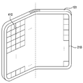
- the electronic device 101 may include a housing.
- the housing may form an appearance of the electronic device 101.
- the display 210 of the electronic device 101 may include at least one area corresponding to at least one surface of the housing.
- a touch sensor disposed in the display 210 may detect a touch input for the at least one area.
- a display area of the display 210 of the electronic device 101 may be included on one surface (eg, a front face) of the housing.
- the display area of the display 210 of the electronic device 101 according to an exemplary embodiment may be included on two or more surfaces of the housing.
- the display area of the display 210 is included in the front, left side, right side, upper side surface, and/or lower side surface of the housing.
- At least a portion of the left, front and right surfaces may be bent according to a certain angle and/or curvature, and boundary lines of the left, front and right surfaces may be included in the curved portion.
- at least a portion of the upper, front, and lower surfaces may be bent according to a certain angle and/or curvature, and boundary lines of each of the upper, front and lower surfaces may be included in the curved portion.
- a display area of the display 210 of the electronic device 101 may be included on at least one surface of each of at least two housings that are pivotally or rotatably connected.
- the display 210 may be a flexible display that can be bent by an external force.
- the at least two housings may be rotatably connected by at least one folding part and/or at least one hinge.
- the display 210 may be disposed in the at least two housings across the folding part and/or the hinge.
- the display 210 may be installed to be supported by the at least two housings.
- the touch sensor may be disposed in the display 210.
- the touch sensor may detect an external object touching the display 210 based on a plurality of cells including the cell 410.
- the cell 410 may be a part of a touch sensor having a specified width and width (eg, 4 mm in width and width).
- a specified width and width eg, 4 mm in width and width.
- at least one display area of the display 210 may be distinguished by a plurality of cells.
- Each of the plurality of cells such as the cell 410 may correspond to a minimum unit of sensor data for identifying an external object.
- the touch sensor may acquire a single numeric value from each of a plurality of cells.
- the touch sensor may identify or output a numerical value such as a capacitance in the cell 410 and/or a sensitivity indicating a pressure of an external object pressing the cell 410.
- the touch sensor when the touch sensor detects an external object based on a capacitive element, the touch sensor is a capacitance measured in each of the plurality of cells included in at least one area of the display 210 and/or the capacitance You can output a plurality of parameters related to.
- the plurality of parameters may correspond to each of the plurality of cells, and may represent a capacitance measured in a corresponding cell and/or a change in capacitance.
- a first processor eg, the touch sensor IC 253 of FIG. 3
- operatively coupled to the touch sensor may acquire coordinates related to an external object based on the capacitance measured in each of the plurality of cells. have. An operation performed by the electronic device 101 according to an exemplary embodiment based on the capacitance will be described in detail with reference to FIG. 5.
- the touch sensor when the touch sensor includes a piezoelectric element, the touch sensor includes a pressure measured in each of the plurality of cells included in at least one area of the display 210 and/or a plurality of parameters related to the pressure. Can be printed.
- the plurality of parameters may correspond to each of the plurality of cells, and may indicate a pressure measured in the corresponding cell and/or a change in pressure.
- the first processor operatively coupled to the touch sensor may acquire coordinates related to the external object based on the pressure measured in each of the plurality of cells.
- FIG. 5 is a flowchart 500 illustrating an operation of a touch circuit of an electronic device according to various embodiments.
- the electronic device may correspond to the electronic device 101 of FIGS. 1 to 3 and 4A to 4C.
- the touch circuit may correspond to the touch circuit 250 of FIGS. 2 to 3.
- the operation of FIG. 5 may be performed by, for example, the touch circuit 250 of FIGS. 2 to 3 and/or the touch sensor IC 253 (or the first processor).
- the touch sensor IC 253 may perform at least one of the operations of FIG. 5 based on, for example, firmware.
- an electronic device includes, at a first point in time, based on first touch information related to capacitance measured from a touch sensor.
- the first location information and first energy information related to the contact surface may be detected.
- the electronic device may detect an external object touching the display and/or a touch input based on the first touch information.
- the electronic device may detect an external object that touches the display corresponding to the touch sensor.
- the first location information detected by the electronic device may indicate a location of an external object touching the display and/or a location of a touch input at a first time point.
- the electronic device may detect an external object touching at least one display area of the display. An operation of the electronic device to determine whether an external object touches the display will be described in detail with reference to FIGS. 6 to 7.
- the first energy information detected by the electronic device may indicate an area of a contact surface between the display and the external object and/or a pressure of the external object at a first point in time.
- the first energy information may include a sum of a numerical value and/or sensitivity obtained from each of a plurality of cells of the touch sensor at a first time point.
- the first energy information may include the number of cells that satisfy a specified condition (eg, a numerical value output from the cell and/or a condition in which the sensitivity exceeds a specified threshold value) among a plurality of cells at a first time point. .
- the electronic device touches the at least one area based on second touch information related to capacitance measured from a touch sensor.
- Second location information of an external object and second energy information related to a contact surface of the external object may be detected.
- the second time point is a time point after the first time point, and may be a time point after a specified period.
- the second location information may indicate a location of an external object touching the display and/or a location of a touch input at the second viewpoint.
- the second energy information may indicate an area of a contact surface between the display and the external object and/or a pressure of the external object at the second viewpoint.
- the second energy information may include a sum of a numerical value and/or sensitivity obtained from each of a plurality of cells of the touch sensor at a second time point.
- the second energy information may include the number of cells that satisfy a specified condition among a plurality of cells at a second time point.
- an electronic device is a hardware component in an electronic device such as a second processor, and includes first location information, second location information, first energy information, or first energy information. It is possible to provide a signal based on at least one of the 2 energy information.
- the signal may be transmitted from the first processor to the second processor every specified period.
- the signal is generated from the hardware component (e.g., a first processor such as the touch sensor IC 253 of FIG. 3) that generated the signal via the communication bus. It may be transmitted to the same second processor and/or the memory 130 of FIG. 3.
- the signal may include location and energy information of an external object and/or a touch input in the identified display every specified period (eg, 120 Hz).
- the electronic device may transmit a first signal including the first location information and the first energy information.
- the electronic device transmits a second signal based on at least one of the second location information and the second energy information can do.
- the signal includes the location of the external object in the display identified at each specified period (eg, the location of the touch input), and energy information related to the contact surface of the identified external object at each specified period May contain a specified value indicating whether it is the maximum.
- the signal includes the position of the external object in the display identified at each specified period, and the signal is transmitted after the contact between the display and the external object is initiated (eg, initiation of a touch input). It may include information related to a point in time when the contact surface of an external object is maximum between the generated points in time.
- the electronic device may generate a signal including information measured from the touch sensor when the location of the external object detected at the current time point and the contact surface of the external object are maximum.
- the electronic device may add information based on sensor data measured from the touch sensor when the contact surface is maximum in a signal including the location of an external object detected at a current time point.
- the electronic device may identify a point in time at which a change in capacitance of the touch sensor caused by an external object becomes maximum.
- the electronic device in response to detection of an external object and/or initiation of a touch input, within a time period in which the external object touches the display, the electronic device is the point at which the change in the information caused by the external object becomes maximum Can be identified.
- the electronic device in response to detection of an external object touching a display, within a time period in which the external object touches at least one display area of the display, the electronic device has a maximum change in the capacitance caused by the external object. You can identify the point of time.
- the point at which the change in capacitance becomes maximum may correspond to the point at which the area of the contact surface between the touch sensor and the external object and/or the pressure of the external object pressing the touch sensor becomes maximum.
- the time point at which the change in capacitance becomes maximum may correspond to the time point at which the number of cells outputting a numerical value equal to or greater than a specified threshold among a plurality of cells included in the touch sensor becomes maximum.
- the time point at which the change in capacitance becomes maximum may correspond to the time point at which the sum of numerical values output from each of the plurality of cells included in the touch sensor becomes maximum.
- the first processor eg, the touch sensor IC 253 of FIG. 3 of the electronic device according to an embodiment is a second processor (eg, the processor 120 of FIG. 3) that is distinct from the first processor. ), a signal generated based on operation 530 may be transmitted.
- the number of signals transmitted from the first processor to the second processor is 2 or more (e.g., a value obtained by dividing the length of the time period by the specified period. ) Can be.
- each of the plurality of signals is a change in the position and capacitance of an external object in the display at the first time point at which the signal is output or generated May include information related to the second time point at which is the maximum.
- the first viewpoint and the second viewpoint may coincide with each other or may be different from each other.
- the difference between the first time point and the second time point may be a multiple of a specified period (eg, a period corresponding to a frequency of 120 Hz). Structures of a plurality of signals transmitted from the first processor to the second processor will be described in detail with reference to FIGS. 11 to 13.
- FIG. 6 is a diagram illustrating an external object identified by an electronic device according to various embodiments and an area of a contact surface between the touch sensor and/or an external object pressing the touch sensor in a state in which the external object touches the touch sensor. It is a graph 600 showing the pressure.
- the electronic device may correspond to the electronic device 101 of FIGS. 1 to 3 and 4A to 4C.
- the touch sensor may correspond to the touch sensor 251 of FIGS. 2 to 3.
- the external object may correspond to at least one of a user's finger and/or a stylus.
- a contact surface between the external object and the touch sensor A curve 610 representing the area of or the pressure of an external object pressing the touch sensor is shown.
- the touch sensor including the capacitive element may identify the area of the contact surface between the touch sensor and the external object that changes along the curve 610 based on the capacitance measured from the capacitive element.
- the touch sensor including the piezoelectric element may identify the pressure of the external object that changes along the curve 610 based on the pressure measured from the piezoelectric element.
- Sensor data output from the touch sensor may include a numerical value (eg, sensitivity) that changes along the curve 610.
- the area of the contact surface and/or the pressure may not be uniformly distributed while an external object touches the touch sensor.
- the area of the contact surface and/or the pressure may be gradually increased and then gradually decreased after a certain point in time.
- Sensor data output from the touch sensor may also indicate a change in the pressure and/or an area of the contact surface that changes before and after the specific time point.
- an embodiment based on the area of the contact surface will be described, and for example, another embodiment based on pressure may be similar to that described below.
- the electronic device determines whether an area of a contact surface between an external object and a touch sensor exceeds a specified first threshold 620 (eg, a touch threshold) based on the sensor data. Can be identified.
- the sensor data may represent a capacitance and/or a change in capacitance of the touch sensor.
- the electronic device may determine that a contact between the external object and the touch sensor has been initiated.
- the first processor operatively coupled to the touch sensor (eg, the touch sensor IC 253 of FIG. 3 ), at a time 625 when the area exceeds the first threshold 620 .
- a second processor eg, the processor 120 of FIG. 3 different from the first processor may notify that the contact between the external object and the touch sensor has started.
- the electronic device determines whether the area is less than the second threshold 630 (for example, a release threshold). Whether or not can be identified.
- the first threshold 620 and the second threshold 630 may be different from each other. For example, the second threshold 630 may be less than the first threshold 620.
- the electronic device may determine that the contact between the external object and the touch sensor is terminated.
- the first processor may notify the second processor that the contact between the external object and the touch sensor is terminated at a point in time 635 where the area is less than the second threshold 630.
- sensor data and/or raw data output from the touch sensor may be related to an external object touching the touch sensor.
- the raw data is a capacitance measured in each of a plurality of cells included in the touch sensor (for example, a plurality of cells including the cell 410 of FIG. 4) and/or a plurality of indicating a change in the capacitance. May include parameters of.
- the first processor receiving the raw data may calculate a coordinate corresponding to the external object based on the raw data.
- the coordinates may correspond to, for example, a center point of a contact surface between an external object and a touch sensor and/or a center of mass.
- the first processor may notify that the contact between the external object and the touch sensor continues while transmitting the calculated coordinates to the second processor. notify continuation of).
- the coordinates may also change without being maintained within the time interval. For example, a deviation may occur between the coordinates and a user's intention to point pointing to a touch sensor and/or a display as an external object.
- the deviation is a typographic error and/or malfunction. (incorrect operation) may be caused.
- the electronic device may identify a time point 640 at which the area of the contact surface becomes maximum.
- the electronic device identifies a touch gesture related to the contact surface based on coordinates corresponding to the external object at the viewpoint 640, for example, coordinates of the center point of the contact surface and/or coordinates of the center of gravity, or You can handle it.
- Information related to the time point 640 at which the area of the contact surface becomes maximum may be included in a signal transmitted from the first processor to the second processor every designated period, or may be transmitted independently of the signal.
- the touch gesture may be, for example, tap, double-tap, drag, slide, long-touch, swipe and/or pinch-to-zoom. -zoom) may correspond to at least one of.
- Identification and/or processing of the touch gesture may be performed by an operating system and/or at least one application running on the electronic device. An operation in which the electronic device identifies or outputs a touch gesture will be described in detail with reference to FIG. 14.
- FIG. 7 is a flowchart 700 illustrating an operation of identifying an external object touching a display by an electronic device according to various embodiments.
- the electronic device may correspond to the electronic device 101 of FIGS. 1 to 3 and 4A to 4C.
- the display may correspond to the display 210 of FIGS. 2 to 3.
- the operations of FIG. 7 may be performed, for example, by the touch circuit 250 and/or the touch sensor IC 253 (or the first processor) disposed in the display 210 of FIGS. 2 to 3. .
- the operations of FIG. 7 may be related to at least one of the operations of FIG. 5.
- the electronic device and/or the first processor may perform at least one of the operations of FIG. 7 every specified period (eg, 120 Hz).
- the electronic device may determine a state related to the external object based on at least one of the operations of FIG. 7. For example, by performing at least one of the operations of FIG. 7, the electronic device may enter either a designated first state indicating that an external object has contacted the display or a designated second state indicating that the external object has been separated from the display. have. The second state may indicate that an external object is not in contact with the display.
- the electronic device may identify the capacitance of each of a plurality of cells in the display.
- the display area of the display may be divided into a plurality of cells based on a unit area in which a touch sensor disposed in the display measures capacitance.
- the first processor disposed in the display of the electronic device may identify a capacitance of each of the plurality of cells and/or a plurality of parameters related to the capacitance. The capacitance may be changed according to an electromagnetic field formed in a space on a display adjacent to a corresponding cell.
- the electronic device may identify an area of a contact surface between a display and an external object based on the identified capacitance.
- the first processor of the electronic device may identify at least one of the area of the contact surface, the electromagnetic field, and the capacitance based on the plurality of parameters corresponding to each of the plurality of cells. For example, assume that an external object is not in contact with the display when the first processor identifies the capacitance of each of the plurality of cells based on operation 710. In this case, the area identified by the first processor based on the operation 720 may be zero (0) within an error range. For example, when an external object comes into contact with the display, the area identified by the first processor based on the operation 720 may change over time.
- the electronic device may determine whether a state related to an external object is a first state indicating contact with a display.
- the first processor performs the operations of FIG. 7 at specified periods, before identifying the capacitance based on the operation 710, the first processor is distinguished from the first state or the first state and It is possible to enter any of the second states indicating that the object has been separated from the display.
- the first processor may determine whether the first processor has entered the first state based on the operation 730.
- the first processor is compared with the area identified in operation 720. You can choose a threshold.
- the electronic device When the electronic device and/or the first processor does not enter the first state (730-No), in operation 740, the electronic device according to various embodiments has an area identified based on operation 720 It may be determined whether it is equal to or greater than the specified first threshold. In an embodiment, in a second state in which an external object is not in contact with the display, the first processor may compare the area and the first threshold based on operation 720.
- the first threshold may correspond to, for example, the first threshold 620 of FIG. 6.
- the electronic device When the area identified based on the operation 720 is greater than or equal to the first threshold (740-Yes), in the operation 750, the electronic device according to various embodiments enters a first state indicating that an external object has contacted the display. You can enter.
- the electronic device When the area identified based on the operation 720 is less than the first threshold (740-No), the electronic device according to various embodiments performs an additional operation related to the area (for example, operation 750). ) May not be performed. In this case, the state of the electronic device and/or the first processor may be maintained in a different state (eg, the second state) distinct from the first state.
- the electronic device When the electronic device and/or the first processor enters the first state (730-Yes), in operation 760, the electronic device according to various embodiments is assigned an area identified based on the operation 720 It may be determined whether or not it is equal to or greater than the second threshold.
- the first processor in a first state in which the external object and the display contact each other, the first processor may compare the area and the second threshold based on operation 720.
- the second threshold may be identical to or different from the first threshold.
- the second threshold may correspond to the second threshold 630 of FIG. 6.
- the electronic device When the area identified based on the operation 720 is less than the second threshold (760-Yes), in operation 770, the electronic device according to various embodiments enters a second state indicating that the external object is separated from the display. You can enter.
- the electronic device When the area identified based on the operation 720 is greater than or equal to the second threshold (760-No), the electronic device according to various embodiments may perform an additional operation related to the area (for example, operation 770). ) May not be performed. In this case, the state of the electronic device and/or the first processor may be maintained in a different state (eg, the first state) distinct from the second state.
- the electronic device and/or the first processor may perform at least one of the operations of FIG. 7 every specified period.
- the area of the contact surface between the external object and the display may be changed as shown in the curve 610 of FIG. 6, and the length of the time period in which the external object and the display are in contact with each other may exceed the specified period. .
- the first processor will not enter the first state indicating that the external object and the display are in contact based on the operation 740-No. I can.
- the first processor may maintain a second state indicating that the external object and the display are not in contact.
- the first processor may enter the first state based on operation 750.
- the first processor may enter the first state at a time point 625 or another time point adjacent to the time point 625 and corresponding to the specified period.
- the first processor may enter the first state.
- the first processor may determine whether to maintain the first state or enter the second state based on a second threshold. Referring to FIG. 6, from the time point 625 to the time point 635 when the area becomes less than or equal to the second threshold, the first processor may maintain the first state.
- the first processor may enter the second state at a time point 635 when the area becomes less than or equal to the second threshold value or another time point adjacent to the time point 635 and corresponding to the specified period.
- the signal generated by the first processor is to enter a first state based on operation 750, enter a second state based on operation 770, and/or maintain the first state. It may contain information related to. For example, the information may indicate a state related to a contact between a display and an external object.
- a signal generated by the first processor and the information included in the signal will be described with reference to FIG. 8.
- FIG. 8 is a signal flow diagram 800 for explaining a signal transmitted between the first processor 253-1 and the second processor 120-1 of an electronic device according to various embodiments of the present disclosure.
- the electronic device may correspond to the electronic device 101 of FIGS. 1 to 3 and 4A to 4C.
- the first processor 253-1 and the second processor 120-1 may correspond to each of the touch sensor IC 253 and the processor 120 of FIG. 3.
- the electronic device of FIG. 8 and/or the first processor 253-1 may perform at least one of the operations of FIGS. 5 and 7.
- a signal transmitted between the first processor 253-1 and the second processor 120-1 may be generated based on a specified period and/or a specified condition.
- the signal may be repeatedly generated every the specified period.
- the signal is a condition in which an external object and a display are in contact with each other and/or a request condition related to the signal (for example, the second processor 120-1 is sent to the first processor 253-1 ). It may be generated by the first processor 253-1 based on a condition for requesting a signal).
- the first processor 253-1 may detect an external object touching the display based on a touch sensor disposed in the display of the electronic device.
- the display and the touch sensor may correspond to the display 210 and the touch sensor 251 of FIG. 3.
- the first processor 253-1 may perform the operation 805 similarly to the operation 510 of FIG. 5.
- the first processor 253-1 performs an operation 805, at least one of the operations of FIG. 7 (eg, operations 710, 720, 730, 740, and 750 of FIG. 7) Can be done based on
- the first processor 253-1 may notify the second processor 120-1 that a contact between the external object and the display has started in response to detection of an external object. In an embodiment, the first processor 253-1 may notify the second processor 120-1 of entering a first state indicating that an external object and a display are in contact. Referring to FIG. 8, after detecting an external object based on an operation 805, the first processor 253-1 informs the second processor 120-1 that contact between the external object and the display has started.
- a first signal 810-1 including a may be transmitted. The information may be included in a designated area within the first signal 810-1. The information may be a designated value (eg, a designated constant such as TOUCH_DOWN or ACTION_DOWN) indicating the start of contact between the external object and the display.
- the first processor 253-1 may obtain the coordinates of an external object touching the display area of the display every specified period 820.
- the designated period 820 may correspond to the driving frequency of the touch sensor.
- the size of the designated period 820 may vary according to a change in the scanning rate of the display of the electronic device. For example, when the refresh rate of the display is changed in the frequency range between 1 Hz and 120 Hz, the length of the period 820 in which the first processor 253-1 acquires coordinates of an external object may also vary according to the display refresh rate. .
- the first processor 253-1 may identify a location of an external object touching the display and/or a change in the location of the external object every specified period 820.
- the first processor 253-1 may output a signal every period 820 designated by the second processor 120-1.
- the signal output at each specified period 820 may include information indicating a position of an external object acquired every specified period 820 and/or a change in the position of the external object.
- the information may include a coordinate value indicating a location of an external object and/or a change amount of the coordinate value based on at least one two-dimensional coordinate space related to the display area of the display.
- the first processor 253-1 transmits the second signal 810 to the second processor 120-1. -2) can be sent.
- a signal transmitted from the first processor 253-1 to the second processor 120-1 in the k-th period after detection of an external object touching the display is referred to as a k-th signal.
- Each of the plurality of signals transmitted by the first processor 253-1 to the second processor 120-1 at a designated period 820 is the first processor 253-1 to the second processor 120-1 It may be a frame and/or a frame signal to be transmitted to.
- the second signal 810-2 is the location of the external object detected after the specified period 820 (that is, the second period) from the time when the first signal 810-1 is transmitted and/ Alternatively, information indicating a change in the location of an external object may be included.
- the first processor 253-1 is transferred to the second processor 120-1.
- a third signal 810-3 may be transmitted.
- the third signal 810-3 may also include information indicating a change in the location of the external object and/or the location of the external object detected after the specified period 820 from the time when the second signal 810-2 is transmitted. I can.
- the first processor 253-1 based on at least one of an area of a contact surface between the external object and the display and/or a pressure of an external object touching the display, the external object And whether or not contact between the displays has been stopped. For example, based on at least one of the operations of FIG. 7 (for example, the operations 710, 720, 730, 760, and 770 of FIG. 7), the first processor 253-1 It can be determined whether or not it is separated from the display.
- the first processor 253-1 includes at least information indicating that a contact between the external object and the display is in progress to the second processor 120-1. Can transmit one signal.
- the second signal 810-2 to the n-1 signal 810-n-1 transmitted after the first signal 810-1 are in progress between the external object and the display.
- This may include at least one of information indicating that the first processor 253-1 is operating based on the first state, and/or information indicating that the external object is before being separated from the display.
- the information may be included in a designated area of each of the second signals 810-2 to n-1th signals 810-n-1.
- the information may be a designated value (eg, designated constants such as TOUCH_MOVE and ACTION_MOVE) indicating that the contact between the external object and the display is in progress.
- the first processor 253-1 transmits a signal including information notifying that the contact between the external object and the display is stopped to the second processor 120-1 can do.
- the first processor 253-1 may notify the second processor 120-1 that the external object and the display enter the separated second state.
- the first processor 253-1 in response to identifying that the external object has been separated from the display, the first processor 253-1 comprises an n-th signal 810-n including information indicating the interruption of contact between the external object and the display. ) Can be sent.
- the information may be included in a designated area within the n-th signal 810-n.
- the information may be a designated value related to the second state (eg, a designated constant such as TOUCH_UP and ACTION_UP).
- the first processor 253-1 is the area of the contact surface between the external object and the display and/or the external
- the pressure of the object can be continuously identified.
- the first processor 253-1 may identify the area and/or the pressure every specified period 820. Based on the identified area and/or the identified pressure, within a time period from the start of the contact between the external object and the display to the present, the first processor 253-1 is the maximum You can obtain the point of view.
- the first processor 253-1 transmits information related to the acquired time point to the second processor 120-1 every specified period 820 (refer to FIG. 8,
- the first signal 810-1 to the n-th signal 810-n) may be combined and/or recorded (may record and/or combine).
- the k-th signal generated in the k-th period after the contact between the external object and the display is started is the coordinates representing the position of the external object within the display identified in the k-th period and the first period. It may include all information related to the location of the external object within the display (within) in the m-th period (1 ⁇ m ⁇ k) in which the area of the contact surface between the external object and the display is the largest between the k-th period. .
- the operation of the first processor 253-1 to record information related to the time point acquired in the signal will be described in detail with reference to FIGS. 10 to 13.
- the first processor 253-1 adds information obtained from the touch sensor when the area of the contact surface becomes maximum in the signal transmitted when the area of the contact surface becomes maximum,
- the k-th signal generated in the k-th period after the contact between the external object and the display is started may include only coordinates indicating the position of the external object in the display identified in the k-th period. Only when the area of the contact surface between the external object and the display becomes maximum in the k-th period, the electronic device may add information indicating that the area of the contact surface is maximum in the k-th signal.
- the second processor 120-1 may include a plurality of signals transmitted from the first processor 253-1 within a time period in which the external object and the display contact each other (for example, the first At least one of the signals 810-1 to the n-th signals 810-n) may be identified.
- the second processor 120-1 determines the location of the external object and/or the location of the external object based on the specified period 820. Change can be monitored. For example, based on the k-th signal received from the first processor 253-1 in the k-th period not less than the first period and less than the n-th period, the second processor 120-1 is You can identify the location of an external object in.
- the second processor 120-1 includes a time when a contact surface between an external object and a display becomes maximum and/or a time when the pressure of the external object becomes maximum (for example, from a plurality of signals).
- the coordinates of the external object touching the display may be identified.
- the second processor 120-1 is external in the display in the m-th period (1 ⁇ m ⁇ k) in which the area of the contact surface between the external object and the display is maximum, based on the k-th signal. You can identify the location of the object.
- the second processor 120-1 may perform at least one function of an application being executed by the second processor 120-1.
- At least one operation performed by the second processor 120-1 in relation to the at least one function will be described in detail with reference to FIG. 14.
- a change in the area of the contact surface from the start of the contact between the external object and the display to the stop will be described in detail with reference to FIGS. 9A to 9B.
- FIGS. 9A to 9B illustrate an external object 910 and a display 210 identified by the electronic device 101 according to various embodiments while the external object 910 touches the display 210 on which the touch sensor is disposed.
- the electronic device 101 may correspond to the electronic device 101 of FIGS. 1 to 3 and 4A to 4C.
- the display 210 may correspond to the display 210 of FIGS. 2 to 3.
- the operation of the electronic device 101 described with reference to FIGS. 9A to 9B may be related to at least one of the operations of FIGS. 5 and 7 to 8.
- the external object 910 may be a rigid object such as a stylus or a nonrigid object such as a user's finger.
- the size and/or shape of a contact surface between the external object 910 and the display 210 may vary according to a pressure applied to the external object 910.
- the electronic device 101 may include at least one hardware component for identifying the area, size, and/or shape of a contact surface of the external object 910 touching the display 210.
- the electronic device 101 may include a touch circuit 250 including the touch sensor 251 of FIGS. 2 to 3 and/or a touch sensor IC 253 (or a first processor).
- the electronic device 101 may identify capacitance measured in each of the plurality of cells within the display 210 from the information of the touch sensor. The capacitance measured in each of the plurality of cells may be changed according to a contact surface between the external object 910 and the display 210. Referring to FIG.
- the electronic device 101 displays sizes 920-1 and 920-of contact surfaces at each of the first, second, third and fourth viewpoints based at least in part on the identified capacitance. 2, 920-3, 920-4) can be identified.
- the interval between two adjacent viewpoints at the first to fourth viewpoints may correspond to a period related to the operation of the touch sensor (eg, a designated period 820 of FIG. 8 ).
- the electronic device 101 may acquire the location of the external object 910 touching the display 210 based on the identified capacitance.
- the location of the external object 910 may mean one coordinate selected from coordinates of the display 210 included in the contact surface between the display 210 and the external object 910.
- the selected coordinates may be instant coordinates indicating the location of the external object 910 at the moment when the contact surface is identified.
- the electronic device 101 may determine the center of gravity of the contact surface as a position of the external object 910 and/or a coordinate (eg, the representative coordinate) corresponding to the external object 910. .
- the electronic device 101 includes coordinates 930-1, 930-2, and 930-related to the external object 910 identified at each of the first to fourth viewpoints based on the identified capacitance. 3, 930-4) is shown.
- Each of the coordinates 930-1, 930-2, 930-3 and 930-4 may correspond to each of the centers of gravity of the contact surfaces identified at the first to fourth viewpoints.
- the electronic device 101 may generate a signal (eg, the first signal 810-1 to the n-th signal 810-n in FIG. 8) including the location of the identified external object 910. .
- the electronic device 101 may generate a signal including information representing each of the coordinates 930-1, 930-2, 930-3, and 930-4 at each of the first to fourth viewpoints. have.
- the signal is transmitted and/or received between a plurality of hardware components included in the electronic device 101 (for example, the first processor 253-1 and the second processor 120-1 in FIG. 8). I can.
- the electronic device 101 includes an external object identified at a plurality of viewpoints, based on sizes of a contact surface between the external object 910 and the display 210 identified at a plurality of viewpoints. Any one of the positions of 910 may be determined as a representative coordinate of the external object 910 within a time period in which the external object 910 and the display 210 contact each other.
- the electronic device 101 based on the sizes of the contact surfaces 920-1, 920-2, 920-3 and 920-4 at each of the first to fourth time points, the electronic device 101 Any one of the coordinates 930-1, 930-2, 930-3, and 930-4 at each of the viewpoint to the fourth viewpoint may be determined as a representative coordinate of the location of the external object 910. For example, since the size of the contact surface 920-4 at the fourth time point is larger than the sizes 920-1, 920-2, and 920-3 of the contact surface at the other time points, the electronic device 101 May determine the instantaneous coordinates 930-4 measured at the fourth viewpoint as the representative coordinates of the external object 910.
- the electronic device 101 controls the UI displayed in the display 210 based on the representative coordinates, thereby maintaining the responsiveness to the touch input by the external object 910 and improving the UI. You can control it precisely.
- the electronic device 101 may display at least one visual element that enables intuitive control by a touch input in the UI.
- the visual element may include, for example, at least one of a button, icon, text, image, video, animation, number picker, progress bar, check box, and/or radio button.
- a button, icon text, image, video, animation, number picker, progress bar, check box, and/or radio button.
- the electronic device 101 may display a UI for inputting text on the display 210 based on a plurality of buttons, such as a soft keyboard, a virtual keyboard, and/or an on-screen keyboard.
- a user touches a part of the UI in the display 210 using a finger (for example, the external object 910 in FIG. 9A)
- the electronic device 101 uses a plurality of cells of the touch sensor.
- the contact surface 920 between the finger and the display 210 can be identified.
- a portion 940 of the touch sensor may include one or more cells, and in the example of FIG. 9B, it is assumed that 9 cells are included in the portion 940.
- the electronic device 101 may obtain sensor data related to capacitance and/or pressure measured in each of the plurality of cells from the plurality of cells.
- each of the numerical values in the part 940 of the touch sensor is sensor data measured in each of the cells included in the part 940, and may correspond to, for example, sensitivity related to the capacitance measured in the cell. .
- a plurality of cells included in a portion 940 of the touch sensor Numerical values obtained from are shown.
- the distribution of numerical values output from each of the plurality of cells of the touch sensor including the portion 940 may also vary.
- the position of the maximum value among the plurality of cells of the touch sensor may vary according to the change of the contact surface 920.
- the obtained numerical values may be used to identify the coordinates of the finger touching the display 210 (eg, coordinates of the center of gravity of the contact surface 920) and/or the size of the contact surface 920.
- the electronic device 101 may identify the coordinates of the finger at each of the plurality of viewpoints t0 to t7.
- the electronic device 101 may identify the size of the contact surface 920 at each of a plurality of viewpoints t0 to t7.
- the electronic device 101 displays the display 210 based on the sum of the numerical values included in at least a portion 940 of the touch sensor. And an area of the contact surface between the fingers.
- the electronic device 101 since the sum of the numerical values at t0 to t7 is 312, 432, 475, 509, 566, 576, 535, and 529, respectively, the electronic device 101 has a size of the contact surface 920 at t5. It can be identified that it is the maximum.
- the electronic device 101 may identify a time point at which the size of the contact surface 920 becomes maximum based on the number of cells that output a numerical value exceeding a threshold (eg, effective sensitivity). have. For example, when the number of cells that output a numerical value exceeding the threshold value is the maximum at t5, the electronic device 101 may determine that the size of the contact surface 920 is the maximum at t5.
- a threshold eg, effective sensitivity
- the electronic device 101 includes a user-selected content, UI, and/or time based on the coordinates identified at a time point (t5) that maximizes the size of the contact surface 920 among a plurality of viewpoints. Elements can be identified relatively accurately. As shown in FIG. 9B, when a user touches a specific button (e key) in the on-screen keyboard, the electronic device 101 maximizes the size of the contact surface 920 based on the coordinates identified at the time point (t5). Thus, the button touched by the user can be identified.
- a specific button e key
- the electronic device 101 may correspond to the coordinates identified at t5 to maximize the size of the contact surface 920.
- the corresponding button may be determined as the button touched by the user.
- the electronic device 101 Touch input can be more accurately identified.
- the electronic device 101 may prevent misrecognition of a touch input by using a point in time when the size of the contact surface 920 is the maximum. In the case of FIG. 9B, the electronic device 101 may reduce typos that may occur in the on-screen keyboard.
- FIG. 10 is a flowchart 1000 for explaining an operation of generating a signal every specified period by an electronic device according to various embodiments while an external object touches a touch sensor.
- the electronic device may correspond to the electronic device 101 of FIGS. 1 to 3 and 4A to 4C.
- the touch sensor may correspond to the touch sensor 251 disposed in the display 210 of FIGS. 2 to 3.
- the operations of FIG. 10 may be performed, for example, by the touch circuit 250 and/or the touch sensor IC 253 (or the first processor) disposed in the display 210 of FIGS. 2 to 3. .
- the operations of FIG. 10 may be performed based on or similarly to at least one of the operations of FIGS. 5 and 7 to 8.
- the electronic device may perform at least one of the operations of FIG. 10.
- the electronic device may perform at least one of the operations of FIG. 10 at specified periods.
- the designated period may correspond to a designated period (eg, the designated period 820 of FIG. 8) for monitoring the position of an external object in the display by the electronic device according to an embodiment.
- the operation of the electronic device in the k-th period corresponding to any one of the first to n-th periods within the time period will be described.
- the electronic device may acquire coordinates of an external object touching the display in the k-th period.
- the electronic device may obtain the coordinates of the external object based on sensor data identified in a plurality of cells, similar to those described with reference to FIGS. 9A to 9B.
- the electronic device may identify the area and/or pressure of the contact surface between the display and the external object at the coordinates of the external object and/or the k-th period.
- the electronic device in operation 1020, includes coordinates of an external object acquired in a k-th period, and displays a display in a time period between the first period and the k-th period.
- a signal based on the maximum value of the area and/or the pressure of the external object touching is generated.
- the electronic device may identify a time point between a first cycle and a kth cycle in which the area and/or the pressure is maximized.
- the maximum value that the electronic device identifies based on the operation 1020 may be changed. For example, when the area and/or pressure of an external object touching the display gradually increases, the maximum value that the electronic device identifies based on the operation 1020 gradually increases from the first to the nth period. Can be.
- the electronic device includes the coordinates of the external object in the k-th period acquired based on the operation 1010, and the area and/or pressure of the external object is maximum between the first period and the k-th period. It is possible to generate a signal based on the in time point.
- the electronic device may provide the generated signal from the first processor that generated the signal to the second processor.
- the signal identifies the coordinates of the external object obtained in the k-th period, as well as the coordinates of the external object obtained at a time point between the first period and the k-th period in which the area and/or pressure of the external object touching the display is maximized. It may further include information for doing.
- the format of the information includes a flag indicating whether the kth period is a time point at which the area and/or the pressure is maximized, a coordinate value obtained at the time point, or a combination of sensor data obtained from the touch sensor at the time point. It may include at least one.
- a structure of a signal generated by an electronic device will be described in detail with reference to FIGS. 11 to 13.
- FIGS. 11 to 13 are diagrams illustrating exemplary structures 1100, 1200, and 1300 of signals generated by an electronic device according to various embodiments.
- the electronic device of FIGS. 11 to 13 may correspond to the electronic device 101 of FIGS. 1 to 3 and 4A to 4C.
- the operation of the electronic device 101 described with reference to FIGS. 11 to 13 may be related to at least one of the operations of FIGS. 5, 7, and 10.
- the operations of the electronic device 101 described with reference to FIGS. 11 to 13 include a first processor (for example, the touch sensor IC 253 in FIG. 3) and a second processor (for example, the electronic device 101 ).
- it may be performed by the processor 120 of FIG. 3.
- 11 to 13 are, for example, based on the operation 530 of FIG. 5 and/or the operation 1030 of FIG. It may be generated by the first processor. At least one of the signals 1100, 1200, and 1300 generated by the first processor may be transmitted to the second processor.
- the electronic device and/or the first processor may include a surface related to a touch sensor (eg, the display 210 of FIGS. 2 to 3) based on information received from the touch sensor at each specified period. Information related to at least one external object touching the top may be obtained. The obtained information may be processed according to a format that can be identified by the first processor and/or the second processor of the electronic device.
- a touch sensor eg, the display 210 of FIGS. 2 to 3
- Information related to at least one external object touching the top may be obtained.
- the obtained information may be processed according to a format that can be identified by the first processor and/or the second processor of the electronic device.
- information included in a signal output from the first processor is bits (B0 to B7) and bytes (BYTE0 to BYTE). 7).
- the first processor of the electronic device transmits the bits of BYTE0 in the order of B0 to B7 to the second processor, and then transmits the bits of BYTE1 in a similar order, thereby transmitting a plurality of bits in the order of BYTE0 to BYTE7. can do.
- the first processor transmits the plurality of bits to the second processor, the plurality of bits are transmitted directly between the first processor and the second processor, or the plurality of bits are transmitted to the first processor and the second processor. It may include stored in a memory (eg, at least a portion of the memory 130 of FIGS. 1 to 3) accessible to all of the processors.
- the first processor may obtain a status (Touch Status), an identifier (TID), and/or a type (Touch Type) of the external object touching the display as information related to the external object.
- the first processor may represent the obtained state of the external object as a value of 2 bits in a designated field and/or part of the signal (eg, B6 to B7 of BYTE0).
- the first processor may divide and store the obtained type of the external object in two designated parts of the signal (eg, B6 to B7 of BYTE6 and B6 to B7 of BYTE7).
- the first processor transfers a part ([3:2]) of 4-bit values representing the external object type in B6 to B7 of BYTE6, and the rest ([1:0]) except for the part of B6 to B7 of BYTE7. ) Can be recorded.
- the state of the external object e.g., None, Press, Move and/or Release
- an identifier (Touch ID) of an external object corresponding to the signal may be recorded.
- the type field (Touch Type) information indicating the type of the external object identified by the first processor (eg, Normal, Hover, Glove, Stylus, Palm) may be recorded.
- the sensitivity and/or numerical value of the touch sensor related to the external object may be recorded.
- a length of a major axis and a length of a minor axis of a contact surface between an external object and a display may be recorded.
- the number of remaining events may be recorded.
- the first processor may obtain coordinates of the position of the external object in the display measured at the time and/or the instant when the signal is generated as information related to the external object.
- the first processor may record the obtained coordinates in the portion 1120 of the signal. 11 to 13, the first processor records the x-coordinates of the acquired coordinates in each of the entire BYTE 1 (8 bits) and part of the BYTE 3 (4 bits) of the signal, and the entire BYTE 2 of the signal (8 bits). And y-coordinates of the obtained coordinates may be recorded in each part (4 bits) of BYTE4.
- the first processor may record the distance between the external object and the display (Z fields of B0 to B5 of BYTE 6 of FIGS. 11 to 13). The distance may be used to process user input based on an external object hovering over the display.
- the first processor may include, for example, based on the operations of FIG. 10, when the area of the contact surface of the external object touching the display is the maximum and/or the outside within the display at the time. You can identify the location of the object.
- the first processor may add information related to the time point and/or the identified location into a signal to be transmitted to the second processor (may insert).
- the signal in a designated part 1110 of a signal, for example, in a Max energy bit field corresponding to B5 of BYTE 7, the signal is a contact surface of an external object.
- a designated value indicating whether the area corresponds to the maximum point can be recorded.
- the format of the designated value may be, for example, a 1-bit Boolean value.
- the first processor may have a specified value corresponding to True in the portion 1110 of the signal (eg, logic 1). (logic one) or high signal (high signal) can be recorded.
- the first processor may have a specified value corresponding to False in the portion 1110 of the signal (e.g., logic 0 (logic zero) or low signal) can be written.
- the first processor includes a portion 1110 such as a Max energy bit field based on a plurality of parameters (eg, sensitivities of FIG. 9B) identified in each of a plurality of cells included in the touch sensor.
- Information indicating the point in time when the area of the contact surface of an external object is maximum can be added.
- the first processor determines the location of the external object identified at each specified period within a portion 1110 of the signal. It can be output by adding a specified value indicating whether the position measured at the point where the change of the parameters of is the maximum.
- the first processor When a plurality of parameters indicate a change in the capacitance of each of the plurality of cells, the first processor at the time when the coordinates related to the external object included in the other part 1120 of the signal are acquired within the part 1110 of the signal. It is possible to combine a parameter indicating whether the change of is maximum.
- Table 1 is an example of information recorded in a signal based on the structure 1100 of FIG. 11 by a first processor according to an embodiment in an exemplary situation in which the sum of a plurality of parameters measured from a touch sensor is changed .
- the sum of a plurality of parameters identified at each of the first time point to the thirteenth time point according to a period designated by the first processor is illustrated.
- the sum of the plurality of parameters may be proportional to an area of a contact surface of an external object touching the touch sensor and/or the display.
- the first processor for example, based on the operations of FIG. 7, the area of the contact surface between the external object and the display exceeds a specified first threshold (eg, the first threshold 620 of FIG. 6 ). It is possible to identify the fourth time point.
- the signal transmitted from the first processor to the second processor at the fourth time point includes the coordinates of the external object identified at the fourth time point in the portion 1120, and starts the contact between the external object and the display in the Touch Status field.
- a specified value to notify (a specified value such as Press, TOUCH_DOWN and/or ACTION_DOWN).
- the point at which the area of the contact surface of the external object is the maximum is the fourth point in time itself (itself), so the first processor corresponds to the Max energy bit field.
- a designated value (1) indicating the point at which the area of the contact surface of the external object is the maximum may be recorded.
- the first processor may identify the sum of a plurality of parameters representing the area of the contact surface of the external object from the touch sensor every specified period. Until the sum is less than a designated second threshold (e.g., the second threshold 630 of FIG. 6) for determining the interruption of contact between the display and the external object, the first processor determines the identified plurality of parameters. Based on, it is possible to track the position of an external object within the display.
- the Touch Status field in at least one signal transmitted from the first processor to the second processor is a designated value indicating that a contact between an external object and a display is in progress (Move, TOUCH_MOVE And/or ACTION_MOVE).
- the first processor may identify the sum 110 of a plurality of parameters representing the area of the contact surface of the external object from the touch sensor. In response to identifying the sum 110 that exceeds the designated second threshold, the first processor may obtain the location of the external object in the display based on the plurality of parameters identified at the fifth time point. The first processor may record the acquired position in the designated portion 1120 of the signal.
- the first processor calculates the sum 110 of the plurality of parameters identified at the fifth time point, based on the operation of FIG. 10, at a time point when the area of the contact surface of the external object before the fifth time point is maximum ( That is, it may be compared with the sum 100 of a plurality of parameters of the fourth viewpoint). Since the sum 110 of the fifth viewpoint exceeds the sum 100 of the fourth viewpoint, the first processor has the maximum area of the contact surface of the external object in the part 1110 of the signal corresponding to the Max energy bit field. A designated value (1) indicating the time point can be recorded.
- the first processor may identify the sum 105 of a plurality of parameters representing the area of the contact surface of the external object from the touch sensor. In response to identifying the sum 105 that exceeds the designated second threshold, the first processor may obtain the location of the external object within the display based on the plurality of parameters identified at the sixth time point. The first processor may record the acquired position in the designated portion 1120 of the signal.
- the first processor calculates the sum 105 of the plurality of parameters identified at the sixth time point, based on the operation of FIG. 10, when the area of the contact surface of the external object before the sixth time point is the maximum ( That is, it may be compared with the sum 110 of the plurality of parameters of the fifth time point). Since the sum 105 of the sixth viewpoint is less than the sum 110 of the fifth viewpoint, the first processor determines that the area of the contact surface of the external object is within a portion 1110 of the signal corresponding to the Max energy bit field. A designated value (0) indicating that the location is not the maximum at the sixth time point when the location is acquired may be recorded.
- the first processor may determine whether the location of the external object in the display and the area of the contact surface of the external object are maximized every specified period after the fourth point in time. For example, until the sum of the plurality of parameters is less than the second threshold, the first processor may determine whether the location of the external object in the display and the area of the contact surface of the external object are maximized every specified period. I can. Referring to Table 1, the first processor may identify a tenth time point when the sum of the plurality of parameters becomes less than the second threshold, based on the operations of FIG. 7, for example.
- the first processor includes the coordinates of the external object identified at the tenth time point with the second processor, and Touch Status A signal including a specified value (eg, Release, TOUCH_UP and/or ACTION_UP) indicating that contact between the external object and the display in the field is to be stopped may be transmitted.
- the part 1110 of the signal corresponding to the Max energy bit field of the signal transmitted at the tenth time point is the sum of the plurality of parameters identified at the tenth time point (70) is the maximum area of the contact surface of the external object. Since it is less than the sum (120) of the plurality of parameters at the time point 10 (referring to the seventh time point in Table 1), the designated value indicating that the area of the contact surface of the external object is not the maximum at the time point 10 (0) It may include.
- the second processor In response to receiving a plurality of signals based on the structure 1100 of FIG. 11, the second processor according to an embodiment includes the value indicated in Table 1 from the first processor at the fourth time point to the tenth time point. , Based on a portion 1110 corresponding to the Max energy bit field in each of the plurality of signals, it is possible to identify a point in time (seventh point in time) at which the area of the contact surface between the external object and the display becomes maximum. Based on the part 1120 of the signal received at the seventh time point, the second processor may identify the coordinates of the external object in the display at the seventh time point.
- the first processor provides the signal in an energy field and/or a Max energy field corresponding to the entire BYTE 8 (8 bits) within a designated portion 1210 of a signal.
- Information indicating the area of the contact surface of the external object identified by the touch sensor may be recorded at a time corresponding to.
- the first processor may record the sum of the plurality of parameters acquired at the corresponding time point in the part 1210 of the plurality of signals transmitted at the fourth time point to the tenth time point.
- each of the plurality of signals transmitted at the fourth time point to the tenth time point may include a sum of a plurality of parameters acquired at each of the fourth time point to the tenth time point.
- the first processor is acquired from a point in time when the contact between the external object and the display starts in a portion of the signal 1210 and when the area of the contact surface of the external object becomes maximum within a point in time corresponding to the signal.
- the sum of one or more parameters can be recorded.
- the first processor may transmit a signal including the sum 110 of the plurality of parameters identified at the fifth time point within the portion 1210 of the signal. have.
- the first processor may transmit a signal including the sum 120 of the plurality of parameters identified at the fifth time point within the portion 1210 of the signal.
- the first processor may transmit a signal including the sum 120 of the plurality of parameters identified at the seventh time point within the portion 1210 of the signal.
- the second processor In response to receiving the plurality of signals based on the structure 1200 of FIG. 12, the second processor according to an embodiment, based on a portion 1210 corresponding to the Max energy field in each of the plurality of signals, It is possible to identify the point in time when the area of the contact surface between the external object and the display becomes maximum. Based on the part 1120 of the signal received at the identified time point, the second processor may identify the coordinates of the external object in the display at the identified time point.
- the first processor may record the coordinates of the external object obtained at a point in time when the area of the contact surface of the external object is the maximum within the designated part 1310 of the signal.
- the first processor records the X coordinates of the external object at the viewpoint in the entire BYTE8 and a part of BYTE10 (B4 to B7), and the external object at the viewpoint in the entire BYTE9 and a portion (B0 to B3) Y coordinates can be recorded.
- the signal transmitted from the first processor to the second processor is a portion 1120 in which the coordinates of the external object acquired at a specific point in time corresponding to the signal are recorded, and within the specific point in time after the contact of the external object starts.
- a portion 1310 in which coordinates of an external object acquired at a point in time when the area of the contact surface of the external object becomes maximum may be recorded.
- Table 2 shows, in an exemplary situation in which the sum of a plurality of parameters measured from a touch sensor is changed, a first processor according to an embodiment of the signal parts 1120 and 1310 based on the structure 1300 of FIG. 13 This is an example of information recorded within.
- the second processor which receives a signal based on the structure 1300 of FIG. 13, includes all of the locations of the external objects at the time when the location of the external object and the area of the contact surface become maximum at a time corresponding to the signal from one signal. Can be identified.
- the operation of the second processor receiving a signal including information related to the location of the external object and the point at which the area of the contact surface becomes maximum will be described in detail. do.
- FIG. 14 is a flowchart 1400 illustrating an operation of processing a plurality of signals transmitted from a first processor by a second processor connected to a first processor of a touch sensor in an electronic device according to various embodiments.
- the electronic device may correspond to the electronic device 101 of FIGS. 1 to 3 and 4A to 4C.
- the touch sensor may correspond to the touch sensor 251 disposed in the display 210 of FIGS. 2 to 3.
- the first processor and the second processor may correspond to each of the touch sensor IC 253 and processor 120 of FIGS. 3 and/or 8.
- the second processor of the electronic device is associated with an external object touching the display, and identifies a signal transmitted from the first processor based on a specified period.
- the first processor according to an embodiment generates a signal including information related to the location of an external object in the display, for example, based on at least one of the operations of FIGS. 5, 7 and/or 10 can do.
- the generated signal may include information related to a location of an external object based on at least one of the structures 1100, 1200, and 1300 of FIGS. 11 to 13.
- the second processor may receive the signal from the first processor at every specified period.
- the second processor of the electronic device includes a first location of an external object and an external object at a first time point at which the signal is generated, based on the identified signal.
- the second position of the external object may be identified at a second point in time when the area and/or pressure of is maximum.
- the second processor may identify the first location of the external object at the first viewpoint based on a designated portion of the signal (eg, a portion 1120 of FIGS. 11 to 13 ).
- the second processor is based on a designated portion of the signal (eg, portions 1110, 1210, 1310 of FIGS.
- the second processor may identify the first position and the second position of the external object at each of the first and second viewpoints that overlap each other or are different from one signal.
- the second processor of the electronic device displays an application being executed by the second processor based on the first location and/or the second location. It can perform at least one function. For example, when an on-screen keyboard is displayed in the display based on an application running in the second processor, the second processor may be configured according to the first position and/or the second position identified based on operation 1420. A user's touch input received within the on-screen keyboard can be processed.
- the second processor For example, at the time when the user completes touching any one key in the on-screen keyboard (for example, the time 635 in FIG. 6 and/or the 10th time in Table 1), the second processor The external object is based on the first position of the external object measured at the first viewpoint as well as the second position of the external object at the second viewpoint where the area of the contact surface of the external object identified according to operation 1420 is the maximum
- the keys in the on-screen keyboard touched by can be identified.
- the second processor may perform an application-related function (eg, a function of receiving a character string from a user based on the identified key) based on the identified key.
- whether the second processor processes the user's touch input based on which of the first location and the second location is based on the user's selection and/or the application running in the second processor.
- the electronic device may process the touch input based on the second position.
- the area of the contact surface is relatively small, such as a stylus, or relatively precise touch control (for example, when a part of the display is enlarged and displayed such as a magnifying glass tool) is required, the electronic device The touch input may be processed based on the second location.
- the electronic device may identify an area of a contact surface of an external object touching a display and/or a touch sensor and/or a pressure of the external object.
- the electronic device may identify a point in time when the area and/or the pressure is maximum within a time period in which the external object and the display contact each other.
- the electronic device may execute at least one function based on the position of the external object in the display at the identified time point. As the electronic device further considers the area of the contact surface of the external object and/or the location of the external object at the point where the pressure of the external object is maximum, the electronic device more accurately identifies the location that the user points to based on the external object. can do.
- An electronic device includes: a housing, a display including at least one area corresponding to at least one surface of the housing, a touch sensor for detecting a touch input to the at least one area, and the touch sensor And a first processor operatively coupled to the display, the touch sensor, and a second processor operatively coupled to the first processor, wherein the first processor is measured from the touch sensor at a first time point.
- first touch information related to capacitance Based on first touch information related to capacitance, first position information of an external object touching the at least one area and first energy information related to a contact surface of the external object are detected, and Based on the second touch information related to the capacitance measured from the touch sensor at a point in time 2, the second location information of the external object touching the at least one area and the second energy information related to the contact surface of the external object are detected.
- the second processor may provide a signal based on at least one of the first location information, the second location information, the first energy information, or the second energy information.
- the first processor at each of the first time point and the second time point spaced apart by a specified period, to the second processor, the first location information, the second location information, the first A signal based on at least one of energy information or the second energy information may be transmitted.
- the first processor includes a change in the capacitance measured from the touch sensor at each of the first time point and the second time point in each of the signals transmitted at the first time point and the second time point.
- a designated value indicating whether is the maximum may be added and transmitted to the second processor.
- the first processor includes the first energy information and the first energy information measured at each of the first time point and the second time point in each of the signals transmitted at the first time point and the second time point. 2
- the energy information may be combined and transmitted to the second processor.
- the first processor in the signal, combines the location information of the external object measured at a point in time at which the change in capacitance is maximum among the first location information and the second location information, It can be transmitted to the second processor.
- the touch sensor transmits, to the first processor, a plurality of parameters corresponding to each of a plurality of cells included in the at least one area and based on a capacitance measured in each of the plurality of cells.
- the first processor may acquire the first location information or the second location information related to the external object based on at least one of the plurality of parameters.
- the second processor in response to identifying a signal provided from the first processor, calculates the coordinates of the external object touching the at least one area at a point in time when the change in capacitance becomes maximum. It is possible to identify and perform at least one function of an application being executed by the second processor based on the identified coordinates of the external object.
- the second processor in response to identifying a plurality of time points at which the change in capacitance is maximum from the signal, is based on the location information of the external object at a last time point among the plurality of time points.
- the at least one function can be performed.
- An electronic device includes a display, a touch sensor disposed on the display, and a processor operatively coupled to the touch sensor, and the processor is, at a first time point, from the touch sensor. Based on the first touch information related to the measured capacitance, first position information of an external object touching the display corresponding to the touch sensor and first energy information related to a contact surface of the external object are detected, and the first Based on second touch information related to capacitance measured from the touch sensor at a second point after point 1, second position information of an external object touching the at least one area and a second position information related to a contact surface of the external object 2 It detects energy information and provides a signal based on at least one of the first location information, the second location information, the first energy information, or the second energy information with a second processor that is distinguished from the processor. I can.
- the processor in the signal, adds and outputs a specified value indicating whether the location information of the external object identified at each specified period is a location measured at a time when the change in capacitance becomes maximum. I can.
- the processor may add and output information obtained by combining a plurality of parameters obtained from the touch sensor at a point in time when the change in capacitance becomes maximum in the signal.
- the processor may add and output a location of the external object touching the display at a point in time when the change in capacitance is maximized in the signal.
- the processor from the information of the touch sensor, corresponding to each of a plurality of cells within the display, and the plurality of parameters based on a capacitance measured in each of the plurality of cells. It is possible to identify and obtain the first energy information or the second energy information based on the identified plurality of parameters.
- the processor may output the signal every specified period.
- An electronic device includes a housing, a display including at least one area corresponding to at least one surface of the housing, and a touch sensor for detecting a touch input to the at least one area.
- a first processor operatively coupled to the touch sensor and the display, and a second processor operatively coupled to the touch sensor and the first processor, wherein the second processor includes an external device that touches the display A first position of the external object in the display at a first point in time when the signal is generated, based on the identified signal and associated with an object, identifying a signal based on a period specified from the first processor, and At a second point in time when at least one of the area or pressure of the external object becomes maximum, the second position of the external object in the display is identified, and at least one of the first position or the second position identified from the signal Based on one, at least one function of an application being executed by the second processor may be performed.
- the second processor identifies the second position corresponding to the second time point based on a parameter included in the signal and indicating whether a change in capacitance of the touch sensor is maximum, and , Based on the identified second location, at least one function of the application being executed by the second processor may be performed.
- the second processor based on the signal, identifies a capacitance of the touch sensor at the second time point, and touches the display at the second time point based on the identified capacitance. Coordinates indicating the second location of the external object may be obtained.
- the second processor included in the signal, identifies the coordinates of the second location of the external object touching the display at the second point of view, and the coordinates of the identified second location Based on, the at least one function may be performed.
- the second processor may perform the at least one function based on at least one of the first position or the second position at a third point in time when the external object is separated from the display. have.
- the first processor determines a first position of the external object touching the display at the first time point, based on information related to the capacitance measured from the touch sensor at the first time point.
- the signal including information related to the second position of the external object in the display is detected at a second point in time when the area or pressure of the external object is maximized, including information related to the first position. And transmits the generated signal to the second processor.
- a computer-readable storage medium storing one or more programs (software modules) may be provided.
- One or more programs stored in a computer-readable storage medium are configured to be executable by one or more processors in an electronic device (device).
- the one or more programs include instructions that cause the electronic device to execute methods according to embodiments described in the claims or specification of the present disclosure.
- These programs include random access memory, non-volatile memory including flash memory, read only memory (ROM), and electrically erasable programmable ROM.
- EEPROM electrically erasable programmable read only memory
- magnetic disc storage device compact disc-ROM (CD-ROM), digital versatile discs (DVDs) or other forms of It may be stored in an optical storage device or a magnetic cassette. Alternatively, it may be stored in a memory composed of a combination of some or all of them. In addition, a plurality of configuration memories may be included.
- the program is through a communication network composed of a communication network such as the Internet, an intranet, a local area network (LAN), a wide LAN (WLAN), or a storage area network (SAN), or a combination thereof. It may be stored in an attachable storage device that can be accessed. Such a storage device may be connected to a device performing an embodiment of the present disclosure through an external port. In addition, a separate storage device on the communication network may access a device performing an embodiment of the present disclosure.
- a communication network such as the Internet, an intranet, a local area network (LAN), a wide LAN (WLAN), or a storage area network (SAN), or a combination thereof. It may be stored in an attachable storage device that can be accessed. Such a storage device may be connected to a device performing an embodiment of the present disclosure through an external port. In addition, a separate storage device on the communication network may access a device performing an embodiment of the present disclosure.
Abstract
다양한 실시예들에 따른 전자 장치(electronic device)는, 하우징, 상기 하우징의 적어도 하나의 면에 대응하는 적어도 하나의 영역을 포함하는 디스플레이, 상기 적어도 하나의 영역에 대한 터치 입력을 검출하기 위한 터치 센서, 상기 터치 센서와 작동적으로 결합된 제1 프로세서 및 상기 디스플레이, 상기 터치 센서 및 상기 제1 프로세서와 작동적으로 결합된 제2 프로세서를 포함할 수 있다. 상기 제1 프로세서는, 제1 시점에서 상기 터치 센서로부터 측정되는 커패시턴스와 관련된 제1 터치 정보에 기반하여, 상기 적어도 하나의 영역을 터치하는 외부 객체의 제1 위치 정보 및 상기 외부 객체의 접촉 면과 관련된 제1 에너지 정보를 탐지하고, 상기 제1 시점 이후의 제2 시점에서 상기 터치 센서로부터 측정되는 커패시턴스와 관련된 제2 터치 정보에 기반하여, 상기 적어도 하나의 영역을 터치하는 외부 객체의 제2 위치 정보 및 상기 외부 객체의 접촉 면과 관련된 제2 에너지 정보를 탐지하고, 상기 제2 프로세서로, 상기 제1 위치 정보, 상기 제2 위치 정보, 상기 제1 에너지 정보 또는 상기 제2 에너지 정보 중 적어도 하나에 기반하는 신호를 제공할 수 있다.
Description
후술되는 다양한 실시예들은 터치 센서를 터치하는 외부 객체의 좌표를 식별하기 위한 전자 장치에 관한 것이다.
최근 디지털 기술의 발달과 함께 이동통신 단말기, 스마트폰(smart phone), 태블릿(tablet) PC(personal computer), 전자수첩, PDA(personal digital assistant), 웨어러블 장치(wearable device) 등과 같은 다양한 유형의 전자 장치가 널리 사용되고 있다. 상기 전자 장치는 터치 스크린과 같이 터치 센서를 포함하는 디스플레이를 포함할 수 있다.
사용자는 디스플레이의 적어도 일부분을 터치하여 전자 장치를 제어할 수 있다. 손가락 및/또는 스타일러스와 같은 외부 객체에 의한 사용자의 터치 입력은, 상기 외부 객체의 접촉 면의 면적, 압력 및/또는 위치는 외부 객체 및 디스플레이가 서로 접촉되어 있는 동안 일정하지 않을 수 있다. 전자 장치가 시간에 따라 변경되는 외부 객체의 접촉 면의 면적, 압력 및/또는 위치를 고려하여 터치 입력을 보다 정확하게 식별하기 위한 방안이 요구될 수 있다.
본 문서에서 이루고자 하는 기술적 과제는 이상에서 언급한 기술적 과제로 제한되지 않으며, 언급되지 않은 또 다른 기술적 과제들은 아래의 기재로부터 본 발명이 속하는 기술분야에서 통상의 지식을 가진 자에게 명확하게 이해될 수 있을 것이다.
다양한 실시예들에 따른 전자 장치(electronic device)는, 하우징, 상기 하우징의 적어도 하나의 면에 대응하는 적어도 하나의 영역을 포함하는 디스플레이, 상기 적어도 하나의 영역에 대한 터치 입력을 검출하기 위한 터치 센서, 상기 터치 센서와 작동적으로 결합된 제1 프로세서 및 상기 디스플레이, 상기 터치 센서 및 상기 제1 프로세서와 작동적으로 결합된 제2 프로세서를 포함하고, 상기 제1 프로세서는, 제1 시점에서 상기 터치 센서로부터 측정되는 커패시턴스와 관련된 제1 터치 정보에 기반하여, 상기 적어도 하나의 영역을 터치하는 외부 객체의 제1 위치 정보 및 상기 외부 객체의 접촉 면과 관련된 제1 에너지 정보를 탐지하고, 상기 제1 시점 이후의 제2 시점에서 상기 터치 센서로부터 측정되는 커패시턴스와 관련된 제2 터치 정보에 기반하여, 상기 적어도 하나의 영역을 터치하는 외부 객체의 제2 위치 정보 및 상기 외부 객체의 접촉 면과 관련된 제2 에너지 정보를 탐지하고, 상기 제2 프로세서로, 상기 제1 위치 정보, 상기 제2 위치 정보, 상기 제1 에너지 정보 또는 상기 제2 에너지 정보 중 적어도 하나에 기반하는 신호를 제공할 수 있다.
다양한 실시예들에 따른 전자 장치(electronic device)는, 디스플레이, 상기 디스플레이에 배치된 터치 센서 및 상기 터치 센서와 작동적으로 결합된 프로세서를 포함하고, 상기 프로세서는, 제1 시점에서 상기 터치 센서로부터 측정되는 커패시턴스와 관련된 제1 터치 정보에 기반하여, 상기 터치 센서에 대응하는 상기 디스플레이를 터치하는 외부 객체의 제1 위치 정보 및 상기 외부 객체의 접촉 면과 관련된 제1 에너지 정보를 탐지하고, 상기 제1 시점 이후의 제2 시점에서 상기 터치 센서로부터 측정되는 커패시턴스와 관련된 제2 터치 정보에 기반하여, 상기 적어도 하나의 영역을 터치하는 외부 객체의 제2 위치 정보 및 상기 외부 객체의 접촉 면과 관련된 제2 에너지 정보를 탐지하고, 상기 프로세서와 구별되는 제2 프로세서로, 상기 제1 위치 정보, 상기 제2 위치 정보, 상기 제1 에너지 정보 또는 상기 제2 에너지 정보 중 적어도 하나에 기반하는 신호를 제공할 수 있다.
다양한 실시예들에 따른 전자 장치(electronic device)는, 하우징, 상기 하우징의 적어도 하나의 면에 대응하는 적어도 하나의 영역을 포함하는 디스플레이, 상기 적어도 하나의 영역에 대한 터치 입력을 검출하기 위한 터치 센서, 상기 터치 센서와 작동적으로 결합된 제1 프로세서 및 상기 디스플레이, 상기 터치 센서 및 상기 제1 프로세서와 작동적으로 결합된 제2 프로세서를 포함하고, 상기 제2 프로세서는, 상기 디스플레이를 터치하는 외부 객체와 관련되고, 상기 제1 프로세서로부터 지정된 주기에 기반하여 신호를 식별하고, 상기 식별된 신호에 기반하여, 상기 신호가 생성된 제1 시점에서 상기 디스플레이 내에서의 상기 외부 객체의 제1 위치 및 상기 외부 객체의 면적 또는 압력 중 적어도 하나가 최대가 되는 제2 시점에서 상기 디스플레이 내에서의 상기 외부 객체의 제2 위치를 식별하고, 상기 신호로부터 식별된 상기 제1 위치 또는 상기 제2 위치 중 적어도 하나에 기반하여, 상기 제2 프로세서에 의해 실행 중인 어플리케이션의 적어도 하나의 기능을 수행할 수 있다.
다양한 실시 예들에 따른 전자 장치 및 그의 방법은, 시간에 따라 변경되는 외부 객체의 접촉 면의 면적, 압력 및/또는 위치를 고려하여 터치 입력을 보다 정확하게 식별함으로써 향상된(enhanced) 사용성(usability)을 제공할 수 있다.
본 개시에서 얻을 수 있는 효과는 이상에서 언급한 효과들로 제한되지 않으며, 언급하지 않은 또 다른 효과들은 아래의 기재로부터 본 개시가 속하는 기술 분야에서 통상의 지식을 가진 자에게 명확하게 이해될 수 있을 것이다.
도 1은, 다양한 실시예들에 따른, 네트워크 환경 내의 전자 장치의 블럭도이다.
도 2는 다양한 실시예들에 따른, 표시 장치의 블록도이다.
도 3은 다양한 실시예들에 따른 터치 회로를 포함하는 전자 장치의 블록도이다.
도 4a 내지 4c는 다양한 실시예들에 따른 전자 장치의 디스플레이에 배치된 터치 센서를 도시한 도면이다.
도 5는 다양한 실시예들에 따른 전자 장치의 터치 회로의 동작을 도시한 흐름도이다.
도 6은, 외부 객체가 터치 센서를 터치하는 상태에서, 다양한 실시예들에 따른 전자 장치가 식별하는 외부 객체 및 터치 센서 사이의 접촉 면의 면적 및/또는 터치 센서를 누르는 외부 객체의 압력을 나타낸 그래프이다.
도 7은 다양한 실시예들에 따른 전자 장치가 디스플레이를 터치하는 외부 객체를 식별하는 동작을 설명하기 위한 흐름도이다.
도 8은 다양한 실시예들에 따른 전자 장치의 제1 프로세서 및 제2 프로세서 사이에서 전달되는 신호를 설명하기 위한 신호 흐름도이다.
도 9a 내지 9b는, 외부 객체가 터치 센서가 배치된 디스플레이를 터치하는 상태에서, 다양한 실시예들에 따른 전자 장치가 식별하는 외부 객체 및 디스플레이 사이의 접촉면의 변화 및 터치 센서의 커패시턴스의 변화를 설명하기 위한 도면이다.
도 10은, 외부 객체가 터치 센서를 터치하는 상태에서, 다양한 실시예들에 따른 전자 장치가 지정된 주기마다 신호를 생성하는 동작을 설명하기 위한 흐름도이다.
도 11 내지 13은 다양한 실시예들에 따른 전자 장치가 생성한 신호의 예시적인 구조들을 도시한 도면들이다.
도 14는 다양한 실시예들에 따른 전자 장치에서, 터치 센서의 제1 프로세서와 연결된 제2 프로세서가 제1 프로세서로부터 송신된 복수의 신호들을 처리하는 동작을 설명하기 위한 흐름도이다.
이하, 본 문서의 다양한 실시 예가 첨부된 도면을 참조하여 기재된다. 그러나, 이는 본 문서에 기재된 기술을 특정한 실시 형태에 대해 한정하려는 것이 아니며, 본 문서의 실시 예의 다양한 변경(modifications), 균등물(equivalents), 및/또는 대체물(alternatives)을 포함하는 것으로 이해되어야 한다. 도면의 설명과 관련하여, 유사한 구성요소에 대해서는 유사한 참조 부호가 사용될 수 있다.
본 문서에서, "가진다", "가질 수 있다", "포함한다" 또는 "포함할 수 있다" 등의 표현은 해당 특징(예: 수치, 기능, 동작, 또는 부품 등의 구성요소)의 존재를 가리키며, 추가적인 특징의 존재를 배제하지 않는다.
본 문서에서, "A 또는 B", "A 또는/및 B 중 적어도 하나," 또는 "A 또는/및 B 중 하나 또는 그 이상" 등의 표현은 함께 나열된 항목들의 모든 가능한 조합을 포함할 수 있다. 예를 들면, "A 또는 B", "A 및 B 중 적어도 하나," 또는 "A 또는 B 중 적어도 하나"는, (1) 적어도 하나의 A를 포함, (2) 적어도 하나의 B를 포함, 또는 (3) 적어도 하나의 A 및 적어도 하나의 B 모두를 포함하는 경우를 모두 지칭할 수 있다.
본 문서에서 사용된 "제1", "제2", "첫째" 또는 "둘째" 등의 표현들은 다양한 구성요소들을, 순서 및/또는 중요도에 상관없이 수식할 수 있고, 한 구성요소를 다른 구성요소와 구분하기 위해 사용될 뿐 해당 구성요소들을 한정하지 않는다. 예를 들면, 제 1 사용자 기기와 제 2 사용자 기기는, 순서 또는 중요도와 무관하게, 서로 다른 사용자 기기를 나타낼 수 있다. 예를 들면, 본 문서에 기재된 권리 범위를 벗어나지 않으면서 제 1 구성요소는 제 2 구성요소로 명명될 수 있고, 유사하게 제 2 구성요소도 제 1 구성요소로 바꾸어 명명될 수 있다.
어떤 구성요소(예: 제 1 구성요소)가 다른 구성요소(예: 제 2 구성요소)에 "(기능적으로 또는 통신적으로) 연결되어((operatively or communicatively) coupled with/to)" 있다거나 "접속되어(connected to)" 있다고 언급된 때에는, 상기 어떤 구성요소가 상기 다른 구성요소에 직접적으로 연결되거나, 다른 구성요소(예: 제 3 구성요소)를 통하여 연결될 수 있다고 이해되어야 할 것이다. 반면에, 어떤 구성요소(예: 제 1 구성요소)가 다른 구성요소(예: 제 2 구성요소)에 "직접 연결되어" 있다거나 "직접 접속되어" 있다고 언급된 때에는, 상기 어떤 구성요소와 상기 다른 구성요소 사이에 다른 구성요소(예: 제 3 구성요소)가 존재하지 않는 것으로 이해될 수 있다.
본 문서에서 사용된 표현 "~하도록 구성된(또는 설정된)(configured to)"은 상황에 따라, 예를 들면, "~에 적합한(suitable for)", "~하는 능력을 가지는(having the capacity to)", "~하도록 설계된(designed to)", "~하도록 변경된(adapted to)", "~하도록 만들어진(made to)" 또는 "~를 할 수 있는(capable of)"과 바꾸어 사용될 수 있다. 용어 "~하도록 구성된(또는 설정된)"은 하드웨어(hardware)적으로 "특별히 설계된(specifically designed to)" 것만을 반드시 의미하지 않을 수 있다. 대신, 어떤 상황에서는, "~하도록 구성된 장치"라는 표현은, 그 장치가 다른 장치 또는 부품들과 함께 "~할 수 있는" 것을 의미할 수 있다. 예를 들면, 문구 "A, B, 및 C를 수행하도록 구성된(또는 설정된) 프로세서"는 해당 동작을 수행하기 위한 전용 프로세서(예: 임베디드 프로세서), 또는 메모리 장치에 저장된 하나 이상의 소프트웨어 프로그램들을 실행함으로써, 해당 동작들을 수행할 수 있는 범용 프로세서(generic-purpose processor)(예: CPU(central processing unit) 또는 AP(application processor))를 의미할 수 있다.
본 문서에서 사용된 용어들은 단지 특정한 실시 예를 설명하기 위해 사용된 것으로, 다른 실시 예의 범위를 한정하려는 의도가 아닐 수 있다. 단수의 표현은 문맥상 명백하게 다르게 뜻하지 않는 한, 복수의 표현을 포함할 수 있다. 기술적이거나 과학적인 용어를 포함해서 여기서 사용되는 용어들은 본 문서에 기재된 기술 분야에서 통상의 지식을 가진 자에 의해 일반적으로 이해되는 것과 동일한 의미를 가질 수 있다. 본 문서에 사용된 용어들 중 일반적인 사전에 정의된 용어들은, 관련 기술의 문맥상 가지는 의미와 동일 또는 유사한 의미로 해석될 수 있으며, 본 문서에서 명백하게 정의되지 않는 한, 이상적이거나 과도하게 형식적인 의미로 해석되지 않는다. 경우에 따라서, 본 문서에서 정의된 용어일지라도 본 문서의 실시 예들을 배제하도록 해석될 수 없다.
본 문서의 다양한 실시 예들에 따르는 전자 장치는, 예를 들면, 스마트폰(smartphone), 태블릿 PC(tablet personal computer), 이동 전화기(mobile phone), 영상 전화기, 전자책 리더기(e-book reader), 데스크탑 PC(desktop personal computer), 랩탑 PC(laptop personal computer), 넷북 컴퓨터(netbook computer), 워크스테이션(workstation), 서버, PDA(personal digital assistant), PMP(portable multimedia player), MP3 플레이어, 모바일 의료기기, 카메라(camera), 또는 웨어러블 장치(wearable device) 중 적어도 하나를 포함할 수 있다. 다양한 실시 예들에 따르면, 웨어러블 장치는 액세서리형(예: 시계, 반지, 팔찌, 발찌, 목걸이, 안경, 콘택트 렌즈, 또는 머리 착용형 장치(head-mounted-device(HMD) 등), 직물 또는 의류 일체형(예: 전자 의복), 신체 부착형(예: 스킨 패드(skin pad) 또는 문신), 또는 생체 이식형(예: implantable circuit) 중 적어도 하나를 포함할 수 있다.
어떤 실시 예들에서, 전자 장치는 가전 제품(home appliance)일 수 있다. 가전 제품은, 예를 들면, 텔레비전, DVD(digital video disk) 플레이어, 오디오, 냉장고, 에어컨, 청소기, 오븐, 전자레인지, 세탁기, 공기 청정기, 셋톱 박스(set-top box), 홈 오토매이션 컨트롤 패널(home automation control panel), 보안 컨트롤 패널(security control panel), TV 박스(예: 삼성 HomeSyncTM, 애플TVTM, 또는 구글 TVTM), 게임 콘솔(예: XboxTM, PlayStationTM), 전자 사전, 전자 키, 캠코더(camcorder), 또는 전자 액자 중 적어도 하나를 포함할 수 있다.
다른 실시 예에서, 전자 장치는, 각종 의료기기(예: 각종 휴대용 의료측정기기(혈당 측정기, 심박 측정기, 혈압 측정기, 또는 체온 측정기 등), MRA(magnetic resonance angiography), MRI(magnetic resonance imaging), CT(computed tomography), 촬영기, 또는 초음파기 등), 네비게이션(navigation) 장치, 위성 항법 시스템(GNSS, global navigation satellite system), EDR(event data recorder), FDR(flight data recorder), 자동차 인포테인먼트(infotainment) 장치, 선박용 전자 장비(예: 선박용 항법 장치, 자이로 콤파스 등), 항공 전자기기(avionics), 보안 기기, 차량용 헤드 유닛(head unit), 산업용 또는 가정용 로봇, 금융 기관의 ATM(automatic teller's machine), 상점의 POS(point of sales), 또는 사물 인터넷 장치(internet of things)(예: 전구, 각종 센서, 전기 또는 가스 미터기, 스프링클러 장치, 화재경보기, 온도조절기(thermostat), 가로등, 토스터(toaster), 운동기구, 온수탱크, 히터, 보일러 등) 중 적어도 하나를 포함할 수 있다.
어떤 실시 예에 따르면, 전자 장치는 가구(furniture) 또는 건물/구조물의 일부, 전자 보드(electronic board), 전자 사인 수신 장치(electronic signature receiving device), 프로젝터(projector), 또는 각종 계측 기기(예: 수도, 전기, 가스, 또는 전파 계측 기기 등) 중 적어도 하나를 포함할 수 있다. 다양한 실시 예들에서, 전자 장치는 전술한 다양한 장치들 중 하나 또는 그 이상의 조합일 수 있다. 어떤 실시 예에 따르는 전자 장치는 플렉서블 전자 장치 또는 폴더블 전자 장치일 수 있다. 또한, 본 문서의 실시 예에 따르는 전자 장치는 전술한 기기들에 한정되지 않으며, 기술 발전에 따르는 새로운 전자 장치를 포함할 수 있다.
본 문서에서, 사용자라는 용어는 전자 장치를 사용하는 사람 또는 전자 장치를 사용하는 장치(예: 인공지능 전자 장치)를 지칭할 수 있다.
이하, 첨부 도면을 참조하여, 다양한 실시 예들을 상세히 설명하면 다음과 같다. 다만, 설명의 편의를 위하여 도면에서는 구성 요소들이 그 크기가 과장 또는 축소될 수 있다. 예컨대, 도면에서 나타난 각 구성의 크기 및 두께는 설명의 편의를 위해 임의로 나타내었으므로, 본 발명이 반드시 도시된 바에 한정되지 않는다.
도 1은, 다양한 실시예들에 따른, 네트워크 환경(100) 내의 전자 장치(101)의 블럭도이다. 도 1을 참조하면, 네트워크 환경(100)에서 전자 장치(101)는 제 1 네트워크(198)(예: 근거리 무선 통신 네트워크)를 통하여 전자 장치(102)와 통신하거나, 또는 제 2 네트워크(199)(예: 원거리 무선 통신 네트워크)를 통하여 전자 장치(104) 또는 서버(108)와 통신할 수 있다. 일실시예에 따르면, 전자 장치(101)는 서버(108)를 통하여 전자 장치(104)와 통신할 수 있다. 일실시예에 따르면, 전자 장치(101)는 프로세서(120), 메모리(130), 입력 장치(150), 음향 출력 장치(155), 표시 장치(160), 오디오 모듈(170), 센서 모듈(176), 인터페이스(177), 햅틱 모듈(179), 카메라 모듈(180), 전력 관리 모듈(188), 배터리(189), 통신 모듈(190), 가입자 식별 모듈(196), 또는 안테나 모듈(197)을 포함할 수 있다. 어떤 실시예에서는, 전자 장치(101)에는, 이 구성요소들 중 적어도 하나(예: 표시 장치(160) 또는 카메라 모듈(180))가 생략되거나, 하나 이상의 다른 구성 요소가 추가될 수 있다. 어떤 실시예에서는, 이 구성요소들 중 일부들은 하나의 통합된 회로로 구현될 수 있다. 예를 들면, 센서 모듈(176)(예: 지문 센서, 홍채 센서, 또는 조도 센서)은 표시 장치(160)(예: 디스플레이)에 임베디드된 채 구현될 수 있다
프로세서(120)는, 예를 들면, 소프트웨어(예: 프로그램(140))를 실행하여 프로세서(120)에 연결된 전자 장치(101)의 적어도 하나의 다른 구성요소(예: 하드웨어 또는 소프트웨어 구성요소)을 제어할 수 있고, 다양한 데이터 처리 또는 연산을 수행할 수 있다. 일실시예에 따르면, 데이터 처리 또는 연산의 적어도 일부로서, 프로세서(120)는 다른 구성요소(예: 센서 모듈(176) 또는 통신 모듈(190))로부터 수신된 명령 또는 데이터를 휘발성 메모리(132)에 로드하고, 휘발성 메모리(132)에 저장된 명령 또는 데이터를 처리하고, 결과 데이터를 비휘발성 메모리(134)에 저장할 수 있다. 일실시예에 따르면, 프로세서(120)는 메인 프로세서(121)(예: 중앙 처리 장치 또는 어플리케이션 프로세서), 및 이와는 독립적으로 또는 함께 운영 가능한 보조 프로세서(123)(예: 그래픽 처리 장치, 이미지 시그널 프로세서, 센서 허브 프로세서, 또는 커뮤니케이션 프로세서)를 포함할 수 있다. 추가적으로 또는 대체적으로, 보조 프로세서(123)은 메인 프로세서(121)보다 저전력을 사용하거나, 또는 지정된 기능에 특화되도록 설정될 수 있다. 보조 프로세서(123)는 메인 프로세서(121)와 별개로, 또는 그 일부로서 구현될 수 있다.
보조 프로세서(123)는, 예를 들면, 메인 프로세서(121)가 인액티브(예: 슬립) 상태에 있는 동안 메인 프로세서(121)를 대신하여, 또는 메인 프로세서(121)가 액티브(예: 어플리케이션 실행) 상태에 있는 동안 메인 프로세서(121)와 함께, 전자 장치(101)의 구성요소들 중 적어도 하나의 구성요소(예: 표시 장치(160), 센서 모듈(176), 또는 통신 모듈(190))와 관련된 기능 또는 상태들의 적어도 일부를 제어할 수 있다. 일실시예에 따르면, 보조 프로세서(123)(예: 이미지 시그널 프로세서 또는 커뮤니케이션 프로세서)는 기능적으로 관련 있는 다른 구성 요소(예: 카메라 모듈(180) 또는 통신 모듈(190))의 일부로서 구현될 수 있다.
메모리(130)는, 전자 장치(101)의 적어도 하나의 구성요소(예: 프로세서(120) 또는 센서모듈(176))에 의해 사용되는 다양한 데이터를 저장할 수 있다. 데이터는, 예를 들어, 소프트웨어(예: 프로그램(140)) 및, 이와 관련된 명령에 대한 입력 데이터 또는 출력 데이터를 포함할 수 있다. 메모리(130)는, 휘발성 메모리(132) 또는 비휘발성 메모리(134)를 포함할 수 있다.
프로그램(140)은 메모리(130)에 소프트웨어로서 저장될 수 있으며, 예를 들면, 운영 체제(142), 미들 웨어(144) 또는 어플리케이션(146)을 포함할 수 있다.
입력 장치(150)는, 전자 장치(101)의 구성요소(예: 프로세서(120))에 사용될 명령 또는 데이터를 전자 장치(101)의 외부(예: 사용자)로부터 수신할 수 있다. 입력 장치(150)은, 예를 들면, 마이크, 마우스, 키보드, 또는 디지털 펜(예:스타일러스 펜)을 포함할 수 있다.
음향 출력 장치(155)는 음향 신호를 전자 장치(101)의 외부로 출력할 수 있다. 음향 출력 장치(155)는, 예를 들면, 스피커 또는 리시버를 포함할 수 있다. 스피커는 멀티미디어 재생 또는 녹음 재생과 같이 일반적인 용도로 사용될 수 있고, 리시버는 착신 전화를 수신하기 위해 사용될 수 있다. 일실시예에 따르면, 리시버는 스피커와 별개로, 또는 그 일부로서 구현될 수 있다.
표시 장치(160)는 전자 장치(101)의 외부(예: 사용자)로 정보를 시각적으로 제공할 수 있다. 표시 장치(160)은, 예를 들면, 디스플레이, 홀로그램 장치, 또는 프로젝터 및 해당 장치를 제어하기 위한 제어 회로를 포함할 수 있다. 일실시예에 따르면, 표시 장치(160)는 터치를 감지하도록 설정된 터치 회로(touch circuitry), 또는 상기 터치에 의해 발생되는 힘의 세기를 측정하도록 설정된 센서 회로(예: 압력 센서)를 포함할 수 있다.
오디오 모듈(170)은 소리를 전기 신호로 변환시키거나, 반대로 전기 신호를 소리로 변환시킬 수 있다. 일실시예에 따르면, 오디오 모듈(170)은, 입력 장치(150)를 통해 소리를 획득하거나, 음향 출력 장치(155), 또는 전자 장치(101)와 직접 또는 무선으로 연결된 외부 전자 장치(예: 전자 장치(102)) (예: 스피커 또는 헤드폰))를 통해 소리를 출력할 수 있다.
센서 모듈(176)은 전자 장치(101)의 작동 상태(예: 전력 또는 온도), 또는 외부의 환경 상태(예: 사용자 상태)를 감지하고, 감지된 상태에 대응하는 전기 신호 또는 데이터 값을 생성할 수 있다. 일실시예에 따르면, 센서 모듈(176)은, 예를 들면, 제스처 센서, 자이로 센서, 기압 센서, 마그네틱 센서, 가속도 센서, 그립 센서, 근접 센서, 컬러 센서, IR(infrared) 센서, 생체 센서, 온도 센서, 습도 센서, 또는 조도 센서를 포함할 수 있다.
인터페이스(177)는 전자 장치(101)이 외부 전자 장치(예: 전자 장치(102))와 직접 또는 무선으로 연결되기 위해 사용될 수 있는 하나 이상의 지정된 프로토콜들을 지원할 수 있다. 일실시예에 따르면, 인터페이스(177)는, 예를 들면, HDMI(high definition multimedia interface), USB(universal serial bus) 인터페이스, SD카드 인터페이스, 또는 오디오 인터페이스를 포함할 수 있다.
연결 단자(178)는, 그를 통해서 전자 장치(101)가 외부 전자 장치(예: 전자 장치(102))와 물리적으로 연결될 수 있는 커넥터를 포함할 수 있다. 일실시예에 따르면, 연결 단자(178)은, 예를 들면, HDMI 커넥터, USB 커넥터, SD 카드 커넥터, 또는 오디오 커넥터(예: 헤드폰 커넥터)를 포함할 수 있다.
햅틱 모듈(179)은 전기적 신호를 사용자가 촉각 또는 운동 감각을 통해서 인지할 수 있는 기계적인 자극(예: 진동 또는 움직임) 또는 전기적인 자극으로 변환할 수 있다. 일실시예에 따르면, 햅틱 모듈(179)은, 예를 들면, 모터, 압전 소자, 또는 전기 자극 장치를 포함할 수 있다.
카메라 모듈(180)은 정지 영상 및 동영상을 촬영할 수 있다. 일실시예에 따르면, 카메라 모듈(180)은 하나 이상의 렌즈들, 이미지 센서들, 이미지 시그널 프로세서들, 또는 플래시들을 포함할 수 있다.
전력 관리 모듈(188)은 전자 장치(101)에 공급되는 전력을 관리할 수 있다. 일실시예에 따르면, 전력 관리 모듈(388)은, 예를 들면, PMIC(power management integrated circuit)의 적어도 일부로서 구현될 수 있다.
배터리(189)는 전자 장치(101)의 적어도 하나의 구성 요소에 전력을 공급할 수 있다. 일실시예에 따르면, 배터리(189)는, 예를 들면, 재충전 불가능한 1차 전지, 재충전 가능한 2차 전지 또는 연료 전지를 포함할 수 있다.
통신 모듈(190)은 전자 장치(101)와 외부 전자 장치(예: 전자 장치(102), 전자 장치(104), 또는 서버(108))간의 직접(예: 유선) 통신 채널 또는 무선 통신 채널의 수립, 및 수립된 통신 채널을 통한 통신 수행을 지원할 수 있다. 통신 모듈(190)은 프로세서(120)(예: 어플리케이션 프로세서)와 독립적으로 운영되고, 직접(예: 유선) 통신 또는 무선 통신을 지원하는 하나 이상의 커뮤니케이션 프로세서를 포함할 수 있다. 일실시예에 따르면, 통신 모듈(190)은 무선 통신 모듈(192)(예: 셀룰러 통신 모듈, 근거리 무선 통신 모듈, 또는 GNSS(global navigation satellite system) 통신 모듈) 또는 유선 통신 모듈(194)(예: LAN(local area network) 통신 모듈, 또는 전력선 통신 모듈)을 포함할 수 있다. 이들 통신 모듈 중 해당하는 통신 모듈은 제 1 네트워크(198)(예: 블루투스, WiFi direct 또는 IrDA(infrared data association) 같은 근거리 통신 네트워크) 또는 제 2 네트워크(199)(예: 셀룰러 네트워크, 인터넷, 또는 컴퓨터 네트워크(예: LAN 또는 WAN)와 같은 원거리 통신 네트워크)를 통하여 외부 전자 장치와 통신할 수 있다. 이런 여러 종류의 통신 모듈들은 하나의 구성 요소(예: 단일 칩)으로 통합되거나, 또는 서로 별도의 복수의 구성 요소들(예: 복수 칩들)로 구현될 수 있다. 무선 통신 모듈(192)은 가입자 식별 모듈(196)에 저장된 가입자 정보(예: 국제 모바일 가입자 식별자(IMSI))를 이용하여 제 1 네트워크(198) 또는 제 2 네트워크(199)와 같은 통신 네트워크 내에서 전자 장치(101)를 확인 및 인증할 수 있다.
안테나 모듈(197)은 신호 또는 전력을 외부(예: 외부 전자 장치)로 송신하거나 외부로부터 수신할 수 있다. 일실시예에 따르면, 안테나 모듈은 서브스트레이트(예: PCB) 위에 형성된 도전체 또는 도전성 패턴으로 이루어진 방사체를 포함하는 하나의 안테나를 포함할 수 있다. 일실시예에 따르면, 안테나 모듈(197)은 복수의 안테나들을 포함할 수 있다. 이런 경우, 제 1 네트워크(198) 또는 제 2 네트워크(199)와 같은 통신 네트워크에서 사용되는 통신 방식에 적합한 적어도 하나의 안테나가, 예를 들면, 통신 모듈(190)에 의하여 상기 복수의 안테나들로부터 선택될 수 있다. 신호 또는 전력은 상기 선택된 적어도 하나의 안테나를 통하여 통신 모듈(190)과 외부 전자 장치 간에 송신되거나 수신될 수 있다. 어떤 실시예에 따르면, 방사체 이외에 다른 부품(예: RFIC)이 추가로 안테나 모듈(197)의 일부로 형성될 수 있다.
상기 구성요소들 중 적어도 일부는 주변 기기들간 통신 방식(예: 버스, GPIO(general purpose input and output), SPI(serial peripheral interface), 또는 MIPI(mobile industry processor interface))를 통해 서로 연결되고 신호(예: 명령 또는 데이터)를 상호간에 교환할 수 있다.
일실시예에 따르면, 명령 또는 데이터는 제 2 네트워크(199)에 연결된 서버(108)를 통해서 전자 장치(101)와 외부의 전자 장치(104)간에 송신 또는 수신될 수 있다. 전자 장치(102, 104) 각각은 전자 장치(101)와 동일한 또는 다른 종류의 장치일 수 있다. 일실시예에 따르면, 전자 장치(101)에서 실행되는 동작들의 전부 또는 일부는 외부 전자 장치들(102, 104, or 108) 중 하나 이상의 외부 장치들에서 실행될 수 있다. 예를 들면, 전자 장치(101)가 어떤 기능이나 서비스를 자동으로, 또는 사용자 또는 다른 장치로부터의 요청에 반응하여 수행해야 할 경우에, 전자 장치(101)는 기능 또는 서비스를 자체적으로 실행시키는 대신에 또는 추가적으로, 하나 이상의 외부 전자 장치들에게 그 기능 또는 그 서비스의 적어도 일부를 수행하라고 요청할 수 있다. 상기 요청을 수신한 하나 이상의 외부 전자 장치들은 요청된 기능 또는 서비스의 적어도 일부, 또는 상기 요청과 관련된 추가 기능 또는 서비스를 실행하고, 그 실행의 결과를 전자 장치(101)로 전달할 수 있다. 전자 장치(101)는 상기 결과를, 그대로 또는 추가적으로 처리하여, 상기 요청에 대한 응답의 적어도 일부로서 제공할 수 있다. 이를 위하여, 예를 들면, 클라우드 컴퓨팅, 분산 컴퓨팅, 또는 클라이언트-서버 컴퓨팅 기술이 이용될 수 있다.
도 2는 다양한 실시예들에 따른, 표시 장치(160)의 블록도(200)이다. 도 2를 참조하면, 표시 장치(160)는 디스플레이(210), 및 이를 제어하기 위한 디스플레이 드라이버 IC(DDI)(230)를 포함할 수 있다. DDI(230)는 인터페이스 모듈(231), 메모리(233)(예: 버퍼 메모리), 이미지 처리 모듈(235), 또는 맵핑 모듈(237)을 포함할 수 있다. DDI(230)은, 예를 들면, 영상 데이터, 또는 상기 영상 데이터를 제어하기 위한 명령에 대응하는 영상 제어 신호를 포함하는 영상 정보를 인터페이스 모듈(231)을 통해 전자 장치 101의 다른 구성요소로부터 수신할 수 있다. 예를 들면, 일실시예에 따르면, 영상 정보는 프로세서(120)(예: 메인 프로세서(121)(예: 어플리케이션 프로세서) 또는 메인 프로세서(121)의 기능과 독립적으로 운영되는 보조 프로세서(123)(예: 그래픽 처리 장치)로부터 수신될 수 있다. DDI(230)는 터치 회로(250) 또는 센서 모듈(176) 등과 상기 인터페이스 모듈(231)을 통하여 커뮤니케이션할 수 있다. 또한, DDI(230)는 상기 수신된 영상 정보 중 적어도 일부를 메모리(233)에, 예를 들면, 프레임 단위로 저장할 수 있다. 이미지 처리 모듈(235)은, 예를 들면, 상기 영상 데이터의 적어도 일부를 상기 영상 데이터의 특성 또는 디스플레이(210)의 특성에 적어도 기반하여 전처리 또는 후처리(예: 해상도, 밝기, 또는 크기 조정)를 수행할 수 있다. 맵핑 모듈(237)은 이미지 처리 모듈(135)를 통해 전처리 또는 후처리된 상기 영상 데이터에 대응하는 전압 값 또는 전류 값을 생성할 수 있다. 일실시예에 따르면, 전압 값 또는 전류 값의 생성은 예를 들면, 디스플레이(210)의 픽셀들의 속성(예: 픽셀들의 배열(RGB stripe 또는 pentile 구조), 또는 서브 픽셀들 각각의 크기)에 적어도 일부 기반하여 수행될 수 있다. 디스플레이(210)의 적어도 일부 픽셀들은, 예를 들면, 상기 전압 값 또는 전류 값에 적어도 일부 기반하여 구동됨으로써 상기 영상 데이터에 대응하는 시각적 정보(예: 텍스트, 이미지, 또는 아이콘)가 디스플레이(210)를 통해 표시될 수 있다.
일실시예에 따르면, 표시 장치(160)는 터치 회로(250)를 더 포함할 수 있다. 터치 회로(250)는 터치 센서(251) 및 이를 제어하기 위한 터치 센서 IC(253)를 포함할 수 있다. 터치 센서 IC(253)는, 예를 들면, 디스플레이(210)의 특정 위치에 대한 터치 입력 또는 호버링 입력을 감지하기 위해 터치 센서(251)를 제어할 수 있다. 예를 들면, 터치 센서 IC(253)는 디스플레이(210)의 특정 위치에 대한 신호(예: 전압, 광량, 저항, 또는 전하량)의 변화를 측정함으로써 터치 입력 또는 호버링 입력을 감지할 수 있다. 터치 센서 IC(253)는 감지된 터치 입력 또는 호버링 입력에 관한 정보(예: 위치, 면적, 압력, 또는 시간)를 프로세서(120) 에 제공할 수 있다. 일실시예에 따르면, 터치 회로(250)의 적어도 일부(예: 터치 센서 IC(253))는 디스플레이 드라이버 IC(230), 또는 디스플레이(210)의 일부로, 또는 표시 장치(160)의 외부에 배치된 다른 구성요소(예: 보조 프로세서(123))의 일부로 포함될 수 있다.
일실시예에 따르면, 표시 장치(160)는 센서 모듈(176)의 적어도 하나의 센서(예: 지문 센서, 홍채 센서, 압력 센서 또는 조도 센서), 또는 이에 대한 제어 회로를 더 포함할 수 있다. 이 경우, 상기 적어도 하나의 센서 또는 이에 대한 제어 회로는 표시 장치(160)의 일부(예: 디스플레이(210) 또는 DDI(230)) 또는 터치 회로(250)의 일부에 임베디드될 수 있다. 예를 들면, 표시 장치(160)에 임베디드된 센서 모듈(176)이 생체 센서(예: 지문 센서)를 포함할 경우, 상기 생체 센서는 디스플레이(210)의 일부 영역을 통해 터치 입력과 연관된 생체 정보(예: 지문 이미지)를 획득할 수 있다. 다른 예를 들면, 표시 장치(160)에 임베디드된 센서 모듈(176)이 압력 센서를 포함할 경우, 상기 압력 센서는 디스플레이(210)의 일부 또는 전체 영역을 통해 터치 입력과 연관된 압력 정보를 획득할 수 있다. 일실시예에 따르면, 터치 센서(251) 또는 센서 모듈(176)은 디스플레이(210)의 픽셀 레이어의 픽셀들 사이에, 또는 상기 픽셀 레이어의 위에 또는 아래에 배치될 수 있다.
본 문서에 개시된 다양한 실시예들에 따른 전자 장치는 다양한 형태의 장치가 될 수 있다. 전자 장치는, 예를 들면, 휴대용 통신 장치 (예: 스마트폰), 컴퓨터 장치, 휴대용 멀티미디어 장치, 휴대용 의료 기기, 카메라, 웨어러블 장치, 또는 가전 장치를 포함할 수 있다. 본 문서의 실시예에 따른 전자 장치는 전술한 기기들에 한정되지 않는다.
본 문서의 다양한 실시예들 및 이에 사용된 용어들은 본 문서에 기재된 기술적 특징들을 특정한 실시예들로 한정하려는 것이 아니며, 해당 실시예의 다양한 변경, 균등물, 또는 대체물을 포함하는 것으로 이해되어야 한다. 도면의 설명과 관련하여, 유사한 또는 관련된 구성요소에 대해서는 유사한 참조 부호가 사용될 수 있다. 아이템에 대응하는 명사의 단수 형은 관련된 문맥상 명백하게 다르게 지시하지 않는 한, 상기 아이템 한 개 또는 복수 개를 포함할 수 있다. 본 문서에서, "A 또는 B", "A 및 B 중 적어도 하나","A 또는 B 중 적어도 하나,""A, B 또는 C," "A, B 및 C 중 적어도 하나,"및 "A, B, 또는 C 중 적어도 하나"와 같은 문구들 각각은 그 문구들 중 해당하는 문구에 함께 나열된 항목들 중 어느 하나, 또는 그들의 모든 가능한 조합을 포함할 수 있다. "제 1", "제 2", 또는 "첫째" 또는 "둘째"와 같은 용어들은 단순히 해당 구성요소를 다른 해당 구성요소와 구분하기 위해 사용될 수 있으며, 해당 구성요소들을 다른 측면(예: 중요성 또는 순서)에서 한정하지 않는다. 어떤(예: 제 1) 구성요소가 다른(예: 제 2) 구성요소에, "기능적으로" 또는 "통신적으로"라는 용어와 함께 또는 이런 용어 없이, "커플드" 또는 "커넥티드"라고 언급된 경우, 그것은 상기 어떤 구성요소가 상기 다른 구성요소에 직접적으로(예: 유선으로), 무선으로, 또는 제 3 구성요소를 통하여 연결될 수 있다는 것을 의미한다.
본 문서에서 사용된 용어 "모듈"은 하드웨어, 소프트웨어 또는 펌웨어로 구현된 유닛을 포함할 수 있으며, 예를 들면, 로직, 논리 블록, 부품, 또는 회로 등의 용어와 상호 호환적으로 사용될 수 있다. 모듈은, 일체로 구성된 부품 또는 하나 또는 그 이상의 기능을 수행하는, 상기 부품의 최소 단위 또는 그 일부가 될 수 있다. 예를 들면, 일실시예에 따르면, 모듈은 ASIC(application-specific integrated circuit)의 형태로 구현될 수 있다.
본 문서의 다양한 실시예들은 기기(machine)(예: 전자 장치(101)) 의해 읽을 수 있는 저장 매체(storage medium)(예: 내장 메모리(136) 또는 외장 메모리(138))에 저장된 하나 이상의 명령어들을 포함하는 소프트웨어(예: 프로그램(140))로서 구현될 수 있다. 예를 들면, 기기(예: 전자 장치(101))의 프로세서(예: 프로세서(120))는, 저장 매체로부터 저장된 하나 이상의 명령어들 중 적어도 하나의 명령을 호출하고, 그것을 실행할 수 있다. 이것은 기기가 상기 호출된 적어도 하나의 명령어에 따라 적어도 하나의 기능을 수행하도록 운영되는 것을 가능하게 한다. 상기 하나 이상의 명령어들은 컴파일러에 의해 생성된 코드 또는 인터프리터에 의해 실행될 수 있는 코드를 포함할 수 있다. 기기로 읽을 수 있는 저장매체 는, 비일시적(non-transitory) 저장매체의 형태로 제공될 수 있다. 여기서, '비일시적'은 저장매체가 실재(tangible)하는 장치이고, 신호(signal)(예: 전자기파)를 포함하지 않는다는 것을 의미할 뿐이며, 이 용어는 데이터가 저장매체에 반영구적으로 저장되는 경우와 임시적으로 저장되는 경우를 구분하지 않는다.
일실시예에 따르면, 본 문서에 개시된 다양한 실시예들에 따른 방법은 컴퓨터 프로그램 제품(computer program product)에 포함되어 제공될 수 있다. 컴퓨터 프로그램 제품은 상품으로서 판매자 및 구매자 간에 거래될 수 있다. 컴퓨터 프로그램 제품은 기기로 읽을 수 있는 저장 매체(예: compact disc read only memory (CD-ROM))의 형태로 배포되거나, 또는 어플리케이션 스토어(예: 플레이 스토어TM)를 통해 또는 두개의 사용자 장치들(예: 스마트폰들) 간에 직접, 온라인으로 배포(예: 다운로드 또는 업로드)될 수 있다. 온라인 배포의 경우에, 컴퓨터 프로그램 제품의 적어도 일부는 제조사의 서버, 어플리케이션 스토어의 서버, 또는 중계 서버의 메모리와 같은 기기로 읽을 수 있는 저장 매체에 적어도 일시 저장되거나, 임시적으로 생성될 수 있다.
다양한 실시예들에 따르면, 상기 기술한 구성요소들의 각각의 구성요소(예: 모듈 또는 프로그램)는 단수 또는 복수의 개체를 포함할 수 있다. 다양한 실시예들에 따르면, 전술한 해당 구성요소들 중 하나 이상의 구성요소들 또는 동작들이 생략되거나, 또는 하나 이상의 다른 구성요소들 또는 동작들이 추가될 수 있다. 대체적으로 또는 추가적으로, 복수의 구성요소들(예: 모듈 또는 프로그램)은 하나의 구성요소로 통합될 수 있다. 이런 경우, 통합된 구성요소는 상기 복수의 구성요소들 각각의 구성요소의 하나 이상의 기능들을 상기 통합 이전에 상기 복수의 구성요소들 중 해당 구성요소에 의해 수행되는 것과 동일 또는 유사하게 수행할 수 있다. 다양한 실시예들에 따르면, 모듈, 프로그램 또는 다른 구성요소에 의해 수행되는 동작들은 순차적으로, 병렬적으로, 반복적으로, 또는 휴리스틱하게 실행되거나, 상기 동작들 중 하나 이상이 다른 순서로 실행되거나, 생략되거나, 또는 하나 이상의 다른 동작들이 추가될 수 있다.
도 3은 다양한 실시예들에 따른 터치 회로(250)를 포함하는 전자 장치(101)의 블록도이다.
일 실시예에서, 전자 장치(101)는 스마트폰, 스마트패드, 태블릿 PC, PDA(Personal Digital Assistance), 랩톱 PC 또는 데스크톱 PC 중 적어도 하나에 대응할 수 있다. 일 실시예에서, 전자 장치(101)는 액세서리형(예: 시계, 반지, 팔찌, 발찌, 목걸이, 안경, 콘택트 렌즈, 또는 머리 착용형 장치(head-mounted-device(HMD)), 직물 또는 의류 일체형(예: 전자 의복), 신체 부착형(예: 스킨 패드(skin pad) 또는 문신), 또는 생체 이식형(예: implantable circuit) 중 적어도 하나를 포함하는 웨어러블 장치(wearable device)에 대응할 수 있다. 일 실시예에서, 전자 장치(101)는 냉장고, TV(television), 청소기, 에어컨(air-conditioner), 세탁기 및 조명 장치와 같은 가전 제품일 수 있다.
도 3을 참고하면, 다양한 실시예들에 따른 전자 장치(101)는 프로세서(120), 메모리(130) 및/또는 표시 장치(160)를 포함할 수 있다. 프로세서(120) 및 메모리(130)는 도 1의 프로세서(120) 및 메모리(130)에 대응할 수 있다. 표시 장치(160)는 도 1 내지 도 2의 표시 장치(160)에 대응할 수 있다. 프로세서(120), 메모리(130) 및 표시 장치(160)는, 예를 들어, 통신 버스(a communication bus)(미도시)에 의해 전기적으로 및/또는 작동적으로 결합될 수 있다(electrically and/or operably coupled).
다양한 실시예들에 따르면, 표시 장치(160)는 디스플레이(210)를 포함할 수 있고, 터치 회로(250) 및/또는 센서 모듈(176)이 디스플레이(210)에 배치될 수 있다. 터치 회로(250)는 터치 센서(251) 및/또는 터치 센서 집적 회로(Integrated Circuit, IC)(253)를 포함할 수 있다. 디스플레이(210), 터치 회로(250), 터치 센서(251) 및 터치 센서 IC(253)는 도 2의 디스플레이(210), 터치 회로(250), 터치 센서(251) 및 터치 센서 IC(253)에 대응할 수 있다. 디스플레이(210), 터치 회로(250), 터치 센서(251) 및 터치 센서 IC(253) 또한, 예를 들어, 상기 통신 버스에 의해 전기적으로 및/또는 작동적으로 결합될 수 있다.
프로세서(120)는 메모리(130) 내에 저장된 하나 이상의 인스트럭션을 실행할 수 있다. 프로세서(120)는 데이터를 처리하기 위한 회로, 예를 들어, IC, ALU(Arithmetic Logic Unit), FPGA(Field Programmable Gate Array) 및 LSI(Large Scale Integration) 중 적어도 하나를 포함할 수 있다. 메모리(130)는 전자 장치(101)와 관련된 데이터를 저장할 수 있다. 메모리(130)는 SRAM(Static Random Access Memory) 또는 DRAM(Dynamic RAM) 등을 포함하는 RAM(Random Access Memory)과 같은 휘발성 메모리를 포함하거나, ROM(Read Only Memory), MRAM(Magnetoresistive RAM), STT-MRAM(Spin-Transfer Torque MRAM), PRAM(Phase-change RAM), RRAM(Resistive RAM), FeRAM(Ferroelectric RAM) 뿐만 아니라 플래시 메모리, eMMC(Embedded Multi Media Card), SSD(Solid State Drive) 등과 같은 비휘발성 메모리를 포함할 수 있다.
메모리(130)는 어플리케이션과 관련된 인스트럭션 및 운영 체제(Operating System, OS)와 관련된 인스트럭션을 저장할 수 있다. 운영 체제는 프로세서(120)에 의해 실행되는 시스템 소프트웨어이다. 프로세서(120)는 운영 체제를 실행함으로써, 전자 장치(101)에 포함된 하드웨어 컴포넌트들을 관리할 수 있다. 운영 체제는 시스템 소프트웨어를 제외한 나머지 소프트웨어인 어플리케이션으로 API(Application Programming Interface)를 제공할 수 있다.
메모리(130) 내에서, 복수의 어플리케이션들의 집합인 어플리케이션이 하나 이상 설치될 수 있다. 어플리케이션이 메모리들(130) 내에 설치되었다는 것은, 어플리케이션이 메모리들(130) 각각에 연결된 프로세서들(120)에 의해 실행될 수 있는 형태(format)로 저장되었음을 의미한다.
표시 장치(160)는 OLED(Organic Light Emitting Diodes), LCD(Liquid Crystal Display) 및 LED(Light Emitting Diodes)를 포함하는 디스플레이(210)를 통해 사용자에게 정보를 시각적으로 출력할 수 있다. 디스플레이(210) 내에 출력되는 정보는, 프로세서(120)에서 실행 중인 운영 체제 및/또는 적어도 하나의 어플리케이션에 의해 결정될 수 있다. 일 실시예에서, 디스플레이(210)를 통해 출력되는 사용자 인터페이스(User Interface, UI)를 보다 직관적으로 제어할 수 있도록, 터치 회로(250)가 디스플레이(210) 내에 배치될 수 있다. 터치 회로(250)가 디스플레이(210) 내에 배치되었다는 것은, 터치 회로(250)의 적어도 일부(예를 들어, 터치 센서(251))가 디스플레이(210)에 포함된 복수의 픽셀들 사이에, 또는 상기 복수의 픽셀들을 포함하는 레이어(예를 들어, 픽셀 레이어)의 위에 또는 아래에 배치되었음을 의미할 수 있다.
터치 회로(250)는, 예를 들어, 터치 센서 패널(Touch Screen Panel, TSP)과 같은 터치 센서(251) 및 상기 터치 센서(251)와 작동적으로 결합되고, 터치 센서(251)를 제어하는 터치 센서 IC(253)를 포함할 수 있다. 터치 센서 IC(253)는 터치 센서(251)를 제어하는 컨트롤러, IC, ALU, FPGA 또는 LSI 중 적어도 하나를 포함할 수 있다. 이하에서는, 제1 프로세서는 터치 센서 IC(253)를 의미할 수 있고, 제2 프로세서는 프로세서(120)를 의미할 수 있다. 상기 터치 센서 패널들은 저항막(resistive film), 정전성 소자(capacitive components), 표면 초음파(surface acoustic wave) 및 적외선(infrared) 중 적어도 하나를 이용하여 TSP를 터치하거나 TSP 위에서 호버링되는 외부 객체(예를 들어, 사용자의 손가락, 스타일러스)의 위치를 탐지할 수 있다.
외부 객체 및 터치 센서(251)가 서로 접촉되어 있는 동안, 손가락과 같은 외부 객체 및 터치 센서(251) 사이의 접촉 면의 면적, 크기 및/또는 형태는 일정하지 않을 수 있다. 예를 들어, 상기 접촉 면의 면적, 크기 및/또는 형태는 시간 영역에서 비균일 하거나 또는 가변적일 수 있다(non-uniform or variable in a time domain). 다양한 실시예들에 따른 전자 장치(101)는 터치 센서(251)에 의해 탐지된 외부 객체의 위치(예를 들어, TSP 내에서의 외부 객체의 좌표)를, 시간 영역에서 터치 센서(251)를 터치하는 외부 객체의 상태(예를 들어, 외부 객체의 접촉 면의 면적, 크기 및/또는 형태)의 변화에 기반하여 처리할 수 있다.
일 실시예에서, 전자 장치(101)는 시간 영역에서, 터치 센서(251) 및 외부 객체 사이의 접촉 면의 면적이 최대가 되는 시점을 식별할 수 있다. 일 실시예에서, 전자 장치(101)는 시간 영역에서, 터치 센서(251)를 누르는 외부 객체의 압력이 최대가 되는 시점을 식별할 수 있다. 전자 장치(101)는, 상기 면적 및/또는 압력이 최대가 되는 시점에서 터치 센서(251)를 터치하는 외부 객체의 위치에 기반하여, 전자 장치(101)에서 실행 중인 운영 체제 및/또는 적어도 하나의 어플리케이션의 기능을 수행할 수 있다.
상술한 바와 같이, 디스플레이(210)를 통해 출력되는 사용자 인터페이스(User Interface, UI)를 보다 직관적으로 제어하기 위하여, 터치 회로(250)가 디스플레이(210) 내에 배치될 수 있다. 다양한 실시예들에 따른 전자 장치(101)는 손가락과 같은 외부 객체를 이용하여 디스플레이(210) 및/또는 터치 센서(251)를 터치하는 사용자의 의도를 보다 정확하게 식별하기 위하여, 시간 영역에서 디스플레이(210) 및/또는 터치 센서(251)를 터치하는 외부 객체의 상태의 변화를 식별할 수 있다. 이하에서는, 도 4a 내지 4c를 참고하여, 터치 회로(250)가 디스플레이(210) 내에 배치되는 전자 장치(101)의 다양한 실시예들을 상세히 설명한다.
도 4a 내지 4c는 다양한 실시예들에 따른 전자 장치(101)의 디스플레이(210)에 배치된 터치 센서를 도시한 도면이다. 도 4a 내지 4c의 전자 장치(101)는 도 1 내지 도 3의 전자 장치(101)에 대응할 수 있다. 도 4a 내지 4c의 디스플레이(210) 및 터치 센서는 도 2 내지 도 3의 디스플레이(210) 및 터치 센서(251)에 대응할 수 있다.
다양한 실시예들에 따른 전자 장치(101)는 하우징을 포함할 수 있다. 하우징은 전자 장치(101)의 외형(appearance)을 형성할 수 있다. 전자 장치(101)의 디스플레이(210)는 하우징의 적어도 하나의 면에 대응하는 적어도 하나의 영역을 포함할 수 있다. 일 실시예에서, 디스플레이(210) 내에 배치된 터치 센서는 상기 적어도 하나의 영역에 대한 터치 입력을 탐지할 수 있다.
도 4a를 참고하면, 일 실시예에 따른 전자 장치(101)의 디스플레이(210)의 표시 영역은 하우징의 어느 한 면(예를 들어, 전면(a front face))에 포함될 수 있다. 도 4b를 참고하면, 일 실시예에 따른 전자 장치(101)의 디스플레이(210)의 표시 영역은 하우징에서 두 개 이상의 면에 포함될 수 있다. 예를 들어, 디스플레이(210)의 표시 영역은 하우징의 전면, 좌측면(left side surface), 우측면(right side surface), 상측면(upper side surface) 및/또는 하측면(lower side surface)에 포함될 수 있다. 상기 좌측면, 전면 및 우측면의 적어도 일부분은 일정한 각도 및/또는 곡률(curvature)에 따라 휘어질 수 있고(be bent), 좌측면, 전면 및 우측면 각각의 경계선은 휘어진 상기 일부분 내에 포함될 수 있다. 유사하게, 상기 상측면, 전면 및 하측면의 적어도 일부분도 일정한 각도 및/또는 곡률에 따라 휘어질 수 있고, 상측면 전면 및 하측면 각각의 경계선은 휘어진 상기 일부분 내에 포함될 수 있다.
도 4c를 참고하면, 일 실시예에 따른 전자 장치(101)의 디스플레이(210)의 표시 영역은 회전 가능하게(pivotably 또는 rotatably) 연결된 적어도 두 개의 하우징들 각각의 적어도 하나의 면에 포함될 수 있다. 도 4c에서, 디스플레이(210)는 외력(an external force)에 의해 휘어질 수 있는 플렉서블 디스플레이일 수 있다. 상기 적어도 두 개의 하우징들은 적어도 하나의 접이부 및/또는 적어도 하나의 힌지에 의해 회전 가능하게 연결될 수 있다. 디스플레이(210)는 접이부 및/또는 힌지를 가로질러 상기 적어도 두 개의 하우징에 배치될 수 있다. 디스플레이(210)는 상기 적어도 두 개의 하우징에 의해 지지되도록 설치될 수 있다.
도 4a 내지 4c에서, 터치 센서는 디스플레이(210) 내에 배치될 수 있다. 터치 센서는 셀(410)을 포함하는 복수의 셀들에 기반하여 디스플레이(210)를 터치하는 외부 객체를 탐지할 수 있다. 셀(410)은 지정된 폭 및 너비(예를 들어, 폭 및 너비가 4 mm)를 가지는 터치 센서의 일부분일 수 있다. 예를 들어, 디스플레이(210)의 적어도 하나의 표시 영역이 복수의 셀들에 의해 구별될 수 있다. 셀(410)과 같은 복수의 셀들 각각은 외부 객체를 식별하기 위한 센서 데이터의 최소 단위에 대응할 수 있다. 일 실시예에서, 터치 센서는 복수의 셀들 각각에서 단일 수치 값(a single numeric value)을 획득할 수 있다. 예를 들어, 터치 센서는 셀(410) 내에서의 커패시턴스 및/또는 셀(410)을 누르는 외부 객체의 압력을 나타내는 감도(sensitivity)와 같은 수치 값을 식별하거나 또는 출력할 수 있다.
일 실시예에서, 터치 센서가 정전성 소자에 기반하여 외부 객체를 탐지하는 경우, 터치 센서는 디스플레이(210)의 적어도 하나의 영역 내에 포함된 상기 복수의 셀들 각각에서 측정된 커패시턴스 및/또는 상기 커패시턴스와 관련된 복수의 파라미터들을 출력할 수 있다. 상기 복수의 파라미터들은 상기 복수의 셀들 각각에 대응하고, 대응하는 셀에서 측정된 커패시턴스 및/또는 커패시턴스의 변화를 나타낼 수 있다. 상기 터치 센서와 작동적으로 결합된 제1 프로세서(예를 들어, 도 3의 터치 센서 IC(253))는, 복수의 셀들 각각에서 측정된 커패시턴스에 기반하여, 외부 객체와 관련된 좌표를 획득할 수 있다. 일 실시예에 따른 전자 장치(101)가 상기 커패시턴스에 기반하여 수행하는 동작은 도 5를 참고하여 상세히 설명한다.
일 실시예에서, 터치 센서가 압전 소자를 포함하는 경우, 터치 센서는 디스플레이(210)의 적어도 하나의 영역 내에 포함된 상기 복수의 셀들 각각에서 측정된 압력 및/또는 상기 압력과 관련된 복수의 파라미터들을 출력할 수 있다. 상기 복수의 파라미터들은 상기 복수의 셀들 각각에 대응하고, 대응하는 셀에서 측정된 압력 및/또는 압력의 변화를 나타낼 수 있다. 상기 터치 센서와 작동적으로 결합된 제1 프로세서는, 복수의 셀들 각각에서 측정된 압력에 기반하여, 외부 객체와 관련된 좌표를 획득할 수 있다.
이하에서 설명되는 다양한 실시예들은, 도 4a의 외관을 가지는 전자 장치(101)를 기준으로 설명될 것이나, 아래에 기술되는 다양한 실시예들은 도 4b 내지 4c의 외관을 가지는 전자 장치(101)에도 적용될 수 있다.
도 5는 다양한 실시예들에 따른 전자 장치의 터치 회로의 동작을 도시한 흐름도(500)이다. 상기 전자 장치는 도 1 내지 도 3 및 도 4a 내지 4c의 전자 장치(101)에 대응할 수 있다. 상기 터치 회로는 도 2 내지 도 3의 터치 회로(250)에 대응할 수 있다. 도 5의 동작은, 예를 들어, 도 2 내지 도 3의 터치 회로(250) 및/또는 터치 센서 IC(253)(또는, 제1 프로세서)에 의해 수행될 수 있다. 터치 센서 IC(253)는, 예를 들어, 펌-웨어에 기반하여 도 5의 동작들 중 적어도 하나를 수행할 수 있다.
도 5를 참고하면, 동작(510)에서, 다양한 실시예들에 따른 전자 장치는, 제1 시점에서, 터치 센서로부터 측정되는 커패시턴스와 관련된 제1 터치 정보에 기반하여, 디스플레이를 터치하는 외부 객체의 제1 위치 정보 및 접촉 면과 관련된 제1 에너지 정보를 탐지할 수 있다. 일 실시예에서, 전자 장치는 상기 제1 터치 정보에 기반하여, 디스플레이를 터치하는 외부 객체 및/또는 터치 입력을 탐지할 수 있다. 일 실시예에서, 디스플레이 내에 배치된 터치 센서의 정보에 기반하여, 전자 장치는 터치 센서에 대응하는 디스플레이를 터치하는 외부 객체를 탐지할 수 있다. 전자 장치가 탐지하는 제1 위치 정보는 제1 시점에서 디스플레이를 터치하는 외부 객체의 위치 및/또는 터치 입력의 위치를 나타낼 수 있다.
일 실시예에서, 터치 센서로부터 측정되는 커패시턴스 및/또는 압력과 관련된 정보에 기반하여, 전자 장치는 디스플레이의 적어도 하나의 표시 영역을 터치하는 외부 객체를 탐지할 수 있다. 전자 장치가, 외부 객체가 디스플레이를 터치하는지 여부를 판단하는 동작은 도 6 내지 도 7을 참고하여 상세히 설명한다. 전자 장치가 탐지하는 제1 에너지 정보는, 제1 시점에서 디스플레이 및 외부 객체 사이의 접촉 면의 면적 및/또는 외부 객체의 압력을 나타낼 수 있다. 상기 제1 에너지 정보는 제1 시점에서 터치 센서의 복수의 셀들 각각에서 획득된 수치 값 및/또는 감도의 합을 포함할 수 있다. 상기 제1 에너지 정보는 제1 시점에서 복수의 셀들 중에서 지정된 조건(예를 들어, 셀에서 출력되는 수치 값 및/또는 감도가 지정된 임계치를 초과하는 조건)을 만족하는 셀의 개수를 포함할 수 있다.
도 5를 참고하면, 동작(520)에서, 제2 시점에서, 다양한 실시예들에 따른 전자 장치는 터치 센서로부터 측정되는 커패시턴스와 관련된 제2 터치 정보에 기반하여, 상기 적어도 하나의 영역을 터치하는 외부 객체의 제2 위치 정보 및 상기 외부 객체의 접촉 면과 관련된 제2 에너지 정보를 탐지할 수 있다. 상기 제2 시점은 상기 제1 시점 이후의 시점으로, 지정된 주기 이후의 시점일 수 있다. 상기 제2 위치 정보는 상기 제2 시점에서 디스플레이를 터치하는 외부 객체의 위치 및/또는 터치 입력의 위치를 나타낼 수 있다. 상기 제2 에너지 정보는 상기 제2 시점에서 디스플레이 및 외부 객체 사이의 접촉 면의 면적 및/또는 외부 객체의 압력을 나타낼 수 있다. 상기 제2 에너지 정보는 제2 시점에서 터치 센서의 복수의 셀들 각각에서 획득된 수치 값 및/또는 감도의 합을 포함할 수 있다. 상기 제2 에너지 정보는 제2 시점에서 복수의 셀들 중에서 지정된 조건을 만족하는 셀의 개수를 포함할 수 있다.
도 5를 참고하면, 동작(530)에서, 다양한 실시예들에 따른 전자 장치는, 제2 프로세서와 같은 전자 장치 내 하드웨어 컴포넌트로, 제1 위치 정보, 제2 위치 정보, 제1 에너지 정보 또는 제2 에너지 정보 중 적어도 하나에 기반하는 신호를 제공할 수 있다. 상기 신호는 지정된 주기 마다 제1 프로세서에서 제2 프로세서로 송신될 수 있다. 상기 신호는 통신 버스를 통해 신호를 생성한 하드웨어 컴포넌트(예를 들어, 도 3의 터치 센서 IC(253)와 같은 제1 프로세서)에서 다른 하드웨어 컴포넌트(예를 들어, 도 3의 프로세서(120)와 같은 제2 프로세서 및/또는 도 3의 메모리(130))로 송신될 수 있다.
일 실시예에서, 상기 신호는 지정된 주기(예를 들어, 120 Hz)마다 식별된 디스플레이 내에서의 외부 객체 및/또는 터치 입력의 위치 및 에너지 정보를 포함할 수 있다. 예를 들어, 제1 시점에 기반하여 제1 위치 정보 및 제1 에너지 정보를 탐지하는 것에 응답하여, 전자 장치는 제1 위치 정보 및 상기 제1 에너지 정보를 포함하는 제1 신호를 송신할 수 있다. 제1 시점 이후 제2 시점에 기반하여 제2 위치 보 및 제2 에너지 정보를 탐지하는 것에 응답하여, 전자 장치는 제2 위치 정보 및 상기 제2 에너지 정보 중 적어도 하나에 기반하는 제2 신호를 송신할 수 있다.
일 실시예에서, 상기 신호는 지정된 주기마다 식별된 디스플레이 내에서의 외부 객체의 위치(예를 들어, 터치 입력의 위치)를 포함하고, 지정된 주기 마다 식별된 외부 객체의 접촉 면과 관련된 에너지 정보가 최대인지 여부를 나타내는 지정된 값을 포함할 수 있다. 일 실시예에서, 상기 신호는 지정된 주기 마다 식별된 디스플레이 내에서의 외부 객체의 위치를 포함하고, 디스플레이 및 외부 객체 사이의 접촉이 개시(예를 들어, 터치 입력의 개시)된 이후부터 상기 신호를 생성하는 시점 사이에서 외부 객체의 접촉 면이 최대인 시점과 관련된 정보를 포함할 수 있다.
예를 들어, 전자 장치는 현재 시점에서 탐지된 외부 객체의 위치 및 외부 객체의 접촉 면이 최대인 시점에서 터치 센서로부터 측정된 정보를 포함하는 신호를 생성할 수 있다. 일 실시예에서, 전자 장치는 현재 시점에서 탐지된 외부 객체의 위치를 포함하는 신호 내에, 상기 접촉 면이 최대인 시점에서 터치 센서로부터 측정된 센서 데이터에 기반하는 정보를 추가할 수 있다. 일 실시예에서, 전자 장치는 외부 객체에 의해 야기되는 터치 센서의 커패시턴스의 변화가 최대가 되는 시점을 식별할 수 있다. 일 실시예에서, 외부 객체의 탐지 및/또는 터치 입력의 개시에 응답하여, 외부 객체가 디스플레이를 터치하는 시간 구간 내에서, 전자 장치는 외부 객체에 의해 야기되는 상기 정보의 변화가 최대가 되는 시점을 식별할 수 있다. 일 실시예에서, 디스플레이를 터치하는 외부 객체의 탐지에 응답하여, 외부 객체가 디스플레이의 적어도 하나의 표시 영역을 터치하는 시간 구간 내에서, 전자 장치는 외부 객체에 의해 야기되는 상기 커패시턴스의 변화가 최대가 되는 시점을 식별할 수 있다.
일 실시예에서, 커패시턴스의 변화가 최대가 되는 시점은, 터치 센서 및 외부 객체 사이의 접촉 면의 면적 및/또는 터치 센서를 누르는 외부 객체의 압력이 최대가 되는 시점에 대응할 수 있다. 일 실시예에서, 커패시턴스의 변화가 최대가 되는 시점은, 터치 센서에 포함된 복수의 셀들 중에서, 지정된 임계치 이상의 수치 값을 출력하는 셀의 개수가 최대가 되는 시점에 대응할 수 있다. 일 실시예에서, 커패시턴스의 변화가 최대가 되는 시점은, 터치 센서에 포함된 복수의 셀들 각각에서 출력된 수치 값들의 합이 최대가 되는 시점에 대응할 수 있다. 전자 장치가 커패시턴스의 변화가 최대가 되는 시점을 식별하는 동작은 도 6을 참고하여 상세히 설명한다.
일 실시예에 따른 전자 장치의 제1 프로세서(예를 들어, 도 3의 터치 센서 IC(253))는, 상기 제1 프로세서와 구별되는 제2 프로세서(예를 들어, 도 3의 프로세서(120))로, 동작(530)에 기반하여 생성된 신호를 송신할 수 있다. 외부 객체가 디스플레이를 터치하는 시간 구간의 길이가 상기 지정된 주기 보다 긴 경우, 제1 프로세서에서 제2 프로세서로 송신되는 신호의 개수는 2 이상(예를 들어, 시간 구간의 길이를 상기 지정된 주기로 나눈 값)이 될 수 있다. 상기 시간 구간 내에서, 복수의 신호들이 제1 프로세서에서 제2 프로세서로 송신되는 경우, 복수의 신호들 각각은 신호를 출력하거나 또는 생성하는 제1 시점에서의 디스플레이 내 외부 객체의 위치 및 커패시턴스의 변화가 최대인 제2 시점과 관련된 정보를 포함할 수 있다. 상기 제1 시점 및 상기 제2 시점은 서로 일치하거나, 또는 서로 다를 수 있다. 일 실시예에서, 상기 제1 시점 및 상기 제2 시점의 차이는 지정된 주기(예를 들어, 120 Hz의 주파수에 대응하는 주기)의 배수일 수 있다. 제1 프로세서에서 제2 프로세서로 송신되는 복수의 신호들의 구조는 도 11 내지 도 13을 참고하여 상세히 설명한다.
도 6은, 외부 객체가 터치 센서를 터치하는 상태에서, 다양한 실시예들에 따른 전자 장치가 식별하는 외부 객체 및 터치 센서 사이의 접촉 면의 면적 및/또는 외부 객체가 터치 센서를 누르는 외부 객체의 압력을 나타낸 그래프(600)이다. 상기 전자 장치는 도 1 내지 도 3 및 도 4a 내지 4c의 전자 장치(101)에 대응할 수 있다. 상기 터치 센서는 도 2 내지 도 3의 터치 센서(251)에 대응할 수 있다. 상기 외부 객체는 사용자의 손가락 및/또는 스타일러스 중 적어도 하나에 대응할 수 있다.
도 6을 참고하면, 외부 객체가 터치 센서의 적어도 일부분(예를 들어, 도 4의 셀(410)과 같은 복수의 셀들 중 적어도 하나)을 터치하는 상태에서, 외부 객체 및 터치 센서 사이의 접촉 면의 면적 또는 터치 센서를 누르는 외부 객체의 압력을 나타낸 곡선(610)이 도시된다. 일 실시예에서, 정전성 소자를 포함하는 터치 센서는, 상기 정전성 소자로부터 측정되는 커패시턴스에 기반하여 곡선(610)을 따라 변화하는 외부 객체 및 터치 센서 사이의 접촉 면의 면적을 식별할 수 있다. 일 실시예에서, 압전성 소자를 포함하는 터치 센서는, 상기 압전성 소자로부터 측정되는 압력에 기반하여 곡선(610)을 따라 변화하는 외부 객체의 압력을 식별할 수 있다.
터치 센서에서 출력되는 센서 데이터는, 곡선(610)을 따라 변화하는 수치 값(예를 들어, 감도)을 포함할 수 있다. 곡선(610)을 참고하면, 상기 접촉 면의 면적 및/또는 상기 압력은, 외부 객체가 터치 센서를 터치하는 동안 균일하게 분포되지 않을 수 있다. 예를 들어, 상기 접촉 면의 면적 및/또는 상기 압력은 점진적으로 증가된 이후, 특정 시점 이후로 점진적으로 감소될 수 있다. 터치 센서에서 출력되는 센서 데이터 또한, 상기 특정 시점을 전후로 변화하는 상기 접촉 면의 면적 및/또는 상기 압력의 변화를 나타낼 수 있다. 이하에서는 접촉 면의 면적에 기반한 일 실시예가 설명되며, 예를 들어, 압력에 기반한 다른 실시예 또한 이하에서 설명되는 바와 유사할 수 있다.
일 실시예에 따른 전자 장치는 상기 센서 데이터에 기반하여, 외부 객체 및 터치 센서 사이의 접촉 면의 면적이 지정된 제1 임계치(620)(예를 들어, 터치 임계치(Touch Threshold))를 초과하는지 여부를 식별할 수 있다. 예를 들어, 센서 데이터는 터치 센서의 커패시턴스 및/또는 커패시턴스의 변화를 나타낼 수 있다.
상기 면적이 제1 임계치(620)를 초과하는 시점(625)부터, 전자 장치는 외부 객체 및 터치 센서 사이의 접촉이 개시(initiated)된 것으로 결정할 수 있다. 일 실시예에서, 터치 센서와 작동적으로 결합된 제1 프로세서(예를 들어, 도 3의 터치 센서 IC(253))는, 상기 면적이 제1 임계치(620)를 초과하는 시점(625)에서, 상기 제1 프로세서와 구별되는 제2 프로세서(예를 들어, 도 3의 프로세서(120))로 외부 객체 및 터치 센서 사이의 접촉이 개시되었음을 알릴 수 있다.
상기 면적이 제1 임계치(620)를 초과하는 시점(625) 이후부터, 일 실시예에 따른 전자 장치는 상기 면적이 제2 임계치(630)(예를 들어, 릴리즈 임계치(Release Threshold)) 미만인지 여부를 식별할 수 있다. 상기 제1 임계치(620) 및 상기 제2 임계치(630)는 서로 상이할 수 있다. 예를 들어, 상기 제2 임계치(630)는 상기 제1 임계치(620) 미만일 수 있다. 상기 면적이 상기 제2 임계치(630) 미만인 시점(635)에서, 전자 장치는 외부 객체 및 터치 센서 사이의 접촉이 종료(terminated)된 것으로 결정할 수 있다. 일 실시예에서, 상기 제1 프로세서는, 상기 면적이 상기 제2 임계치(630) 미만인 시점(635)에서, 상기 제2 프로세서로 외부 객체 및 터치 센서 사이의 접촉이 종료되었음을 알릴 수 있다.
도 6을 참고하면, 시점들(625, 635) 사이의 시간 구간에서, 터치 센서에서 출력되는 센서 데이터 및/또는 로우 데이터는 터치 센서를 터치하는 외부 객체와 관련될 수 있다. 예를 들어, 상기 로우 데이터는 터치 센서에 포함된 복수의 셀들(예를 들어, 도 4의 셀(410)을 포함하는 복수의 셀들) 각각에서 측정된 커패시턴스 및/또는 상기 커패시턴스의 변화를 나타내는 복수의 파라미터들을 포함할 수 있다. 상기 로우 데이터를 수신한 제1 프로세서는, 상기 로우 데이터에 기반하여 외부 객체에 대응하는 좌표를 계산할 수 있다. 상기 좌표는, 예를 들어, 외부 객체 및 터치 센서 사이의 접촉 면의 중심 점 및/또는 무게 중심(center of mass)에 대응할 수 있다. 일 실시예에서, 제1 프로세서는 시점(625) 이후 및 시점(635) 이전에서, 상기 계산된 좌표를 제2 프로세서로 전달하면서, 외부 객체 및 터치 센서 사이의 접촉이 계속됨을 알릴 수 있다(may notify continuation of).
상기 접촉 면이 시점들(625, 635) 사이의 시간 구간에서 변경됨에 따라, 상기 좌표 또한 시간 구간 내에서 유지되지 않고 변경될 수 있다. 예를 들어, 상기 좌표 및 외부 객체로 터치 센서 및/또는 디스플레이를 가리키는 사용자의 의도(a user's intention to point) 사이에 편차(deviation)가 발생될 수 있다. 디스플레이내에 표시되는 가상 키보드(virtual keyboard, on-screen keyboard or soft-keyboard) 및/또는 게임 어플리케이션에 의해 디스플레이 내에 표시되는 제어 패드(control pad)에서, 상기 편차는 오타(typographic error) 및/또는 오동작(incorrect operation)을 야기할 수 있다.
상기 편차를 줄이거나 또는 회피하기 위하여(to avoid or reduce), 다양한 실시예들에 따른 전자 장치는 접촉 면의 면적이 최대가 되는 시점(640)을 식별할 수 있다. 전자 장치는 시점(640)에서의 외부 객체에 대응하는 좌표, 예를 들어, 상기 접촉 면의 중심 점의 좌표 및/또는 무게 중심의 좌표에 기반하여, 상기 접촉 면과 관련된 터치 제스쳐를 식별하거나 또는 처리할 수 있다. 접촉면의 면적이 최대가 되는 시점(640)과 관련된 정보는, 제1 프로세서에서 제2 프로세서로 지정된 주기 마다 송신되는 신호에 포함되거나, 상기 신호와 독립적으로 송신될 수 있다. 상기 터치 제스쳐는, 예를 들어, 탭(tap), 더블-탭(double-tap), 드래그, 슬라이드, 롱-터치(long-touch), 스와이프 및/또는 핀치-투-줌(pinch-to-zoom) 중 적어도 하나에 대응할 수 있다. 터치 제스쳐의 식별 및/또는 처리는, 전자 장치에서 실행 중인 운영 체제 및/또는 적어도 하나의 어플리케이션에 의해 수행될 수 있다. 전자 장치가 터치 제스쳐를 식별하거나 또는 출력하는 동작은 도 14를 참고하여 상세히 설명한다.
도 7은 다양한 실시예들에 따른 전자 장치가 디스플레이를 터치하는 외부 객체를 식별하는 동작을 설명하기 위한 흐름도(700)이다. 상기 전자 장치는 도 1 내지 도 3 및 도 4a 내지 4c의 전자 장치(101)에 대응할 수 있다. 상기 디스플레이는 도 2 내지 도 3의 디스플레이(210)에 대응할 수 있다. 도 7의 동작들은, 예를 들어, 도 2 내지 도 3의 디스플레이(210) 내에 배치된 터치 회로(250) 및/또는 터치 센서 IC(253)(또는, 제1 프로세서)에 의해 수행될 수 있다.
도 7의 동작들은 도 5의 동작들 중 적어도 하나와 관련될 수 있다. 일 실시예에서, 전자 장치 및/또는 상기 제1 프로세서는 지정된 주기(예를 들어, 120 Hz)마다 도 7의 동작들 중 적어도 하나를 수행할 수 있다. 일 실시예에서, 전자 장치는 도 7의 동작들 중 적어도 하나에 기반하여 외부 객체와 관련된 상태를 결정할 수 있다. 예를 들어, 전자 장치는 도 7의 동작들 중 적어도 하나를 수행하여, 외부 객체가 디스플레이에 접촉되었음을 나타내는 지정된 제1 상태 또는 외부 객체가 디스플레이로부터 분리되었음을 나타내는 지정된 제2 상태 중 어느 하나로 진입할 수 있다. 상기 제2 상태는, 외부 객체가 디스플레이에 접촉하고 있지 않음을 나타낼 수 있다.
도 7을 참고하면, 동작(710)에서, 다양한 실시예들에 따른 전자 장치는 디스플레이 내에서의 복수의 셀들 각각의 커패시턴스를 식별할 수 있다. 일 실시예에서, 디스플레이의 표시 영역은, 디스플레이 내에 배치된 터치 센서가 커패시턴스를 측정하는 단위 영역에 기반하여 복수의 셀들로 구별될 수 있다. 일 실시예에서, 전자 장치의 디스플레이 내에 배치된 제1 프로세서는, 상기 복수의 셀들 각각의 커패시턴스 및/또는 상기 커패시턴스와 관련된 복수의 파라미터들을 식별할 수 있다. 상기 커패시턴스는 대응하는 셀에 인접한 디스플레이 위의 공간 내에 형성된 전자기장에 따라 변경될 수 있다.
도 7을 참고하면, 동작(720)에서, 다양한 실시예들에 따른 전자 장치는 식별된 커패시턴스에 기반하여 디스플레이 및 외부 객체 사이의 접촉 면의 면적을 식별할 수 있다. 일 실시예에서, 전자 장치의 제1 프로세서는 복수의 셀들 각각에 대응하는 상기 복수의 파라미터들에 기반하여, 상기 접촉 면의 면적, 상기 전자기장 또는 상기 커패시턴스 중 적어도 하나를 식별할 수 있다. 예를 들어, 제1 프로세서가 동작(710)에 기반하여 복수의 셀들 각각의 커패시턴스를 식별하는 시점에서, 외부 객체가 디스플레이에 접촉되어 있지 않은 것으로 가정하자. 이 경우, 제1 프로세서가 동작(720)에 기반하여 식별하는 상기 면적은 오차 범위 내의 zero(0)일 수 있다. 예를 들어, 외부 객체가 디스플레이에 접촉된 경우, 제1 프로세서가 동작(720)에 기반하여 식별하는 상기 면적은 시간에 따라 변경될 수 있다.
도 7을 참고하면, 동작(730)에서, 다양한 실시예들에 따른 전자 장치는, 외부 객체와 관련된 상태가 디스플레이와의 접촉을 나타내는 제1 상태인지 판단할 수 있다. 제1 프로세서가 지정된 주기마다 도 7의 동작들을 수행하는 일 실시예에서, 동작(710)에 기반하여 커패시턴스를 식별하기 이전에, 제1 프로세서는 상기 제1 상태 또는 상기 제1 상태와 구별되고 외부 객체가 디스플레이로부터 분리되었음을 나타내는 제2 상태 중 어느 하나로 진입할 수 있다. 이 경우, 제1 프로세서는 동작(730)에 기반하여, 제1 프로세서가 제1 상태에 진입하였는지 여부를 판단할 수 있다. 일 실시예에서, 전자 장치 및/또는 제1 프로세서가 상기 제1 상태 또는 상기 제2 상태 중 어느 상태로 진입하였는지 여부에 기반하여, 제1 프로세서는, 동작(720)에서 식별된 면적과 비교될 임계치를 선택할 수 있다.
전자 장치 및/또는 제1 프로세서가 상기 제1 상태로 진입하지 않은 경우(730-아니오), 동작(740)에서, 다양한 실시예들에 따른 전자 장치는 동작(720)에 기반하여 식별된 면적이 지정된 제1 임계치 이상인지 여부를 판단할 수 있다. 일 실시예에서, 외부 객체가 디스플레이에 접촉하고 있지 않은 제2 상태에서, 제1 프로세서는 동작(720)에 기반하여 상기 면적 및 상기 제1 임계치를 비교할 수 있다. 상기 제1 임계치는, 예를 들어, 도 6의 제1 임계치(620)에 대응할 수 있다.
동작(720)에 기반하여 식별된 면적이 제1 임계치 이상인 경우(740-예), 동작(750)에서, 다양한 실시예들에 따른 전자 장치는, 외부 객체가 디스플레이에 접촉되었음을 나타내는 제1 상태로 진입할 수 있다. 동작(720)에 기반하여 식별된 면적이 제1 임계치 미만인 경우(740-아니오), 다양한 실시예들에 따른 전자 장치는 상기 면적과 관련된 추가적인 동작(additional operation)(예를 들어, 동작(750))을 수행하지 않을 수 있다. 이 경우, 전자 장치 및/또는 제1 프로세서의 상태는 상기 제1 상태와 구별되는 다른 상태(예를 들어, 상기 제2 상태)로 유지될 수 있다.
전자 장치 및/또는 제1 프로세서가 상기 제1 상태로 진입한 경우(730-예), 동작(760)에서, 다양한 실시예들에 따른 전자 장치는 동작(720)에 기반하여 식별된 면적이 지정된 제2 임계치 이상인지 여부를 판단할 수 있다. 일 실시예에서, 외부 객체 및 디스플레이가 서로 접촉하는 제1 상태에서, 제1 프로세서는 동작(720)에 기반하여 상기 면적 및 상기 제2 임계치를 비교할 수 있다. 상기 제2 임계치는 상기 제1 임계치에 일치하거나 또는 다를 수 있다. 예를 들어, 상기 제2 임계치는 도 6의 제2 임계치(630)에 대응할 수 있다.
동작(720)에 기반하여 식별된 면적이 제2 임계치 미만인 경우(760-예), 동작(770)에서, 다양한 실시예들에 따른 전자 장치는, 외부 객체가 디스플레이로부터 분리되었음을 나타내는 제2 상태로 진입할 수 있다. 동작(720)에 기반하여 식별된 면적이 제2 임계치 이상인 경우(760-아니오), 다양한 실시예들에 따른 전자 장치는 상기 면적과 관련된 추가적인 동작(additional operation)(예를 들어, 동작(770))을 수행하지 않을 수 있다. 이 경우, 전자 장치 및/또는 제1 프로세서의 상태는 상기 제2 상태와 구별되는 다른 상태(예를 들어, 상기 제1 상태)로 유지될 수 있다.
상술한 바와 같이, 전자 장치 및/또는 제1 프로세서는 지정된 주기 마다 도 7의 동작들 중 적어도 하나를 수행할 수 있다. 예를 들어, 외부 객체 및 디스플레이 사이의 접촉 면의 면적이 도 6의 곡선(610)과 같이 변경될 수 있고, 외부 객체 및 디스플레이가 서로 접촉되는 시간 구간의 길이가 상기 지정된 주기를 초과할 수 있다. 이 경우, 접촉 면의 면적이 동작(740)의 제1 임계치로 증가되기 이전에, 제1 프로세서는 동작(740-아니오)에 기반하여 외부 객체 및 디스플레이가 접촉됨을 나타내는 제1 상태로 진입하지 않을 수 있다. 도 6을 참고하면, 상기 면적이 제1 임계치(620)를 초과하는 시점(625) 이전에, 제1 프로세서는 외부 객체 및 디스플레이가 접촉되지 않음을 나타내는 제2 상태를 유지할 수 있다. 접촉 면의 면적이 동작(740)의 제1 임계치를 초과한 이후, 제1 프로세서는 동작(750)에 기반하여 상기 제1 상태로 진입할 수 있다. 도 6을 참고하면, 시점(625) 또는 상기 시점(625)에 인접하고 상기 지정된 주기에 대응하는 다른 시점에서, 제1 프로세서는 상기 제1 상태로 진입할 수 있다. 제1 상태로 진입한 이후, 제1 프로세서는 제2 임계치에 기반하여 상기 제1 상태를 유지할지 또는 상기 제2 상태로 진입할지 여부를 결정할 수 있다. 도 6을 참고하면, 시점(625) 이후부터 상기 면적이 제2 임계치 이하가 되는 시점(635)까지, 제1 프로세서는 제1 상태를 유지할 수 있다. 상기 면적이 제2 임계치 이하가 되는 시점(635) 또는 상기 시점(635)에 인접하고 상기 지정된 주기에 대응하는 다른 시점에서, 제1 프로세서는 제2 상태로 진입할 수 있다.
일 실시예에서, 제1 프로세서가 생성하는 신호는, 동작(750)에 기반하는 제1 상태로의 진입, 동작(770)에 기반하는 제2 상태로의 진입 및/또는 상기 제1 상태의 유지와 관련된 정보를 포함할 수 있다. 예를 들어, 상기 정보는 디스플레이 및 외부 객체 사이의 접촉과 관련된 상태를 나타낼 수 있다. 이하에서는, 도 8을 참고하여, 제1 프로세서가 생성하는 신호 및 상기 신호에 포함된 상기 정보의 일 예를 설명한다.
도 8은 다양한 실시예들에 따른 전자 장치의 제1 프로세서(253-1) 및 제2 프로세서(120-1) 사이에서 전달되는 신호를 설명하기 위한 신호 흐름도(800)이다. 상기 전자 장치는 도 1 내지 도 3 및 도 4a 내지 4c의 전자 장치(101)에 대응할 수 있다. 상기 제1 프로세서(253-1) 및 상기 제2 프로세서(120-1)는 도 3의 터치 센서 IC(253) 및 프로세서(120) 각각에 대응할 수 있다. 도 8의 전자 장치 및/또는 제1 프로세서(253-1)는 도 5 및 도 7의 동작들 중 적어도 하나를 수행할 수 있다.
제1 프로세서(253-1) 및 제2 프로세서(120-1) 사이에서 전달되는 신호는, 지정된 주기 및/또는 지정된 조건에 기반하여 생성될 수 있다. 예를 들어, 상기 신호는 상기 지정된 주기 마다 반복적으로 생성될 수 있다. 예를 들어, 상기 신호는 외부 객체 및 디스플레이가 서로 접촉되는 조건 및/또는 상기 신호와 관련된 요청하는 조건(예를 들어, 제2 프로세서(120-1)가 제1 프로세서(253-1)로 상기 신호를 요청하는 조건)에 기반하여 제1 프로세서(253-1)에 의해 생성될 수 있다.
도 8을 참고하면, 동작(805)에서, 제1 프로세서(253-1)는 전자 장치의 디스플레이 내에 배치된 터치 센서에 기반하여, 디스플레이를 터치하는 외부 객체를 탐지할 수 있다. 상기 디스플레이 및 상기 터치 센서는 도 3의 디스플레이(210) 및 터치 센서(251)에 대응할 수 있다. 일 실시예에서, 제1 프로세서(253-1)는 동작(805)을, 도 5의 동작(510)과 유사하게 수행할 수 있다. 일 실시예에서, 제1 프로세서(253-1)는 동작(805)을, 도 7의 동작들 중 적어도 하나(예를 들어, 도 7의 동작들(710, 720, 730, 740, 750))에 기반하여 수행할 수 있다.
일 실시예에서, 제1 프로세서(253-1)는 제2 프로세서(120-1)로, 외부 객체의 탐지에 응답하여, 외부 객체 및 디스플레이 사이의 접촉이 개시되었음을 알릴 수 있다. 일 실시예에서, 제1 프로세서(253-1)는 제2 프로세서(120-1)로, 외부 객체 및 디스플레이가 접촉됨을 나타내는 제1 상태로 진입함을 알릴 수 있다. 도 8을 참고하면, 동작(805)에 기반하여 외부 객체를 탐지한 이후, 제1 프로세서(253-1)는 제2 프로세서(120-1)로 외부 객체 및 디스플레이 사이의 접촉이 개시되었음을 알리는 정보를 포함하는 제1 신호(810-1)를 송신할 수 있다. 상기 정보는 상기 제1 신호(810-1) 내에서의(within) 지정된 영역에 포함될 수 있다. 상기 정보는 외부 객체 및 디스플레이 사이의 접촉의 시작을 나타내는 지정된 값(예를 들어, TOUCH_DOWN, ACTION_DOWN과 같은 지정된 상수)일 수 있다.
제1 상태에서, 일 실시예에 따른 제1 프로세서(253-1)는 디스플레이의 표시 영역을 터치하는 외부 객체의 좌표를 지정된 주기(820)마다 획득할 수 있다. 지정된 주기(820)는 터치 센서의 구동 주파수에 대응할 수 있다. 일 실시예에서, 상기 지정된 주기(820)의 크기는, 전자 장치의 디스플레이의 주사율의 변화에 따라 달라질 수 있다. 예를 들어, 디스플레이의 주사율이 1Hz 내지 120Hz 사이의 주파수 범위에서 변경되는 경우, 제1 프로세서(253-1)가 외부 객체의 좌표를 획득하는 주기(820)의 길이 또한 디스플레이 주사율에 따라 달라질 수 있다. 일 실시예에서, 제1 프로세서(253-1)는 지정된 주기(820)마다 디스플레이를 터치하는 외부 객체의 위치 및/또는 외부 객체의 위치의 변화를 식별할 수 있다. 제1 상태에서, 일 실시예에 따른 제1 프로세서(253-1)는 제2 프로세서(120-1)로 지정된 주기(820) 마다 신호를 출력할 수 있다. 지정된 주기(820) 마다 출력되는 신호는, 지정된 주기(820)마다 획득된 외부 객체의 위치 및/또는 외부 객체의 위치의 변화를 나타내는 정보를 포함할 수 있다. 상기 정보는 디스플레이의 표시 영역과 관련된 적어도 하나의 2차원의 좌표 공간에 기반하여 외부 객체의 위치를 나타내는 좌표 값 및/또는 상기 좌표 값의 변화량을 포함할 수 있다.
도 8을 참고하면, 제1 신호(810-1)를 송신한 시점부터 지정된 주기(820) 이후에, 제1 프로세서(253-1)는 제2 프로세서(120-1)로 제2 신호(810-2)를 송신할 수 있다. 이하에서는, 디스플레이를 터치한 외부 객체를 탐지한 이후의 제k 주기에서 제1 프로세서(253-1)부터 제2 프로세서(120-1)로 송신되는 신호를 제k 신호라 한다. 제1 프로세서(253-1)가 제2 프로세서(120-1)로 지정된 주기(820) 마다 송신하는 복수의 신호들 각각은, 제1 프로세서(253-1)가 제2 프로세서(120-1)로 송신하는 프레임 및/또는 프레임 신호일 수 있다.
상술한 바와 같이, 상기 제2 신호(810-2)는 제1 신호(810-1)를 송신한 시점부터 지정된 주기(820) 이후(즉, 제2 주기)에 탐지된 외부 객체의 위치 및/또는 외부 객체의 위치의 변화를 나타내는 정보를 포함할 수 있다. 유사하게, 제2 신호(810-2)를 송신한 시점 부터 지정된 주기(820) 이후에(즉, 제3 주기에), 제1 프로세서(253-1)는 제2 프로세서(120-1)로 제3 신호(810-3)를 송신할 수 있다. 제3 신호(810-3) 또한 제2 신호(810-2)를 송신한 시점 부터 지정된 주기(820) 이후에 탐지된 외부 객체의 위치 및/또는 외부 객체의 위치의 변화를 나타내는 정보를 포함할 수 있다.
제1 상태에서, 일 실시예에 따른 제1 프로세서(253-1)는, 외부 객체 및 디스플레이 사이의 접촉 면의 면적 및/또는 디스플레이를 터치하는 외부 객체의 압력 중 적어도 하나에 기반하여, 외부 객체 및 디스플레이 사이의 접촉이 중단되었는지 여부를 판단할 수 있다. 예를 들어, 제1 프로세서(253-1)는 도 7의 동작들 중 적어도 하나(예를 들어, 도 7의 동작들(710, 720, 730, 760, 770))에 기반하여, 외부 객체가 디스플레이로부터 분리되었는지 여부를 판단할 수 있다.
제1 상태에서, 외부 객체가 디스플레이로부터 분리되지 않은 경우, 제1 프로세서(253-1)는 제2 프로세서(120-1)로 외부 객체 및 디스플레이 사이의 접촉이 진행 중임을 알리는 정보를 포함하는 적어도 하나의 신호들을 송신할 수 있다. 도 7을 참고하면, 제1 신호(810-1) 이후 송신되는 제2 신호(810-2) 내지 제n-1 신호(810-n-1)들은, 외부 객체 및 디스플레이 사이의 접촉이 진행 중임을 알리는 정보, 제1 프로세서(253-1)가 제1 상태에 기반하여 작동 중임을 나타내는 정보 및/또는 외부 객체가 디스플레이로부터 분리되기 이전임을 알리는 정보 중 적어도 하나를 포함할 수 있다. 상기 정보는 상기 제2 신호(810-2) 내지 제n-1 신호(810-n-1)들 각각의 지정된 영역에 포함될 수 있다. 상기 정보는 외부 객체 및 디스플레이 사이의 접촉이 진행 중임을 나타내는 지정된 값(예를 들어, TOUCH_MOVE, ACTION_MOVE와 같은 지정된 상수)일 수 있다.
제1 상태에서, 외부 객체가 디스플레이로부터 분리되는 경우, 제1 프로세서(253-1)는 제2 프로세서(120-1)로 외부 객체 및 디스플레이 사이의 접촉이 중단됨을 알리는 정보를 포함하는 신호를 송신할 수 있다. 일 실시예에서, 제1 프로세서(253-1)는 제2 프로세서(120-1)로, 외부 객체 및 디스플레이가 분리된 제2 상태로 진입함을 알릴 수 있다. 도 8을 참고하면, 외부 객체가 디스플레이로부터 분리되었음을 식별하는 것에 응답하여, 제1 프로세서(253-1)는 외부 객체 및 디스플레이 사이의 접촉의 중단을 나타내는 정보를 포함하는 제n 신호(810-n)를 송신할 수 있다. 상기 정보는 상기 제n 신호(810-n) 내에서의(within) 지정된 영역에 포함될 수 있다. 상기 정보는 상기 제2 상태와 관련된 지정된 값(예를 들어, TOUCH_UP, ACTION_UP과 같은 지정된 상수)일 수 있다.
다양한 실시예들에 따르면, 외부 객체 및 디스플레이 사이의 접촉이 시작된 이후부터 중단될 때까지, 제1 프로세서(253-1)는 외부 객체 및 디스플레이 사이의 접촉 면의 면적 및/또는 디스플레이를 터치하는 외부 객체의 압력을 연속적으로 식별할 수 있다. 예를 들어, 제1 프로세서(253-1)는 지정된 주기(820)마다 상기 면적 및/또는 상기 압력을 식별할 수 있다. 식별된 면적 및/또는 식별된 압력에 기반하여, 외부 객체 및 디스플레이 사이의 접촉이 시작된 이후부터 현재까지의 시간 구간 내에서, 제1 프로세서(253-1)는 상기 면적 및/또는 상기 압력이 최대인 시점을 획득할 수 있다.
일 실시예에서, 제1 프로세서(253-1)는 획득된 시점과 관련된 정보를, 지정된 주기(820)마다 제2 프로세서(120-1)로 송신되는 하나 이상의 신호들(도 8을 참고하면, 제1 신호(810-1) 내지 제n 신호(810-n))에 결합하거나 및/또는 기록할 수 있다(may record and/or combine). 예를 들어, 외부 객체 및 디스플레이 사이의 접촉이 시작된 이후의 제k 주기에서 생성되는 제k 신호는, 제k 주기에서 식별된 디스플레이 내에서의(within) 외부 객체의 위치를 나타내는 좌표 및 제1 주기 내지 제k 주기 사이에서 외부 객체 및 디스플레이 사이의 접촉 면의 면적이 최대인 제m 주기(1 ≤ m ≤ k)에서 디스플레이 내에서의(within) 외부 객체의 위치와 관련된 정보 전부를 포함할 수 있다. 제1 프로세서(253-1)가 신호 내에 획득된 시점과 관련된 정보를 기록하는 동작은 도 10 내지 도 13을 참고하여 상세히 설명한다.
일 실시예에서, 제1 프로세서(253-1)는 접촉 면의 면적이 최대가 되는 시점에서 송신되는 신호 내에, 상기 접촉 면의 면적이 최대가 되는 시점에서 터치 센서로부터 획득된 정보를 추가하고, 접촉 면의 면적이 최대가 되지 않는 시점에서는 상기 시점에서 식별된 외부 객체의 위치만 추가할 수 있다. 예를 들어, 외부 객체 및 디스플레이 사이의 접촉이 시작된 이후의 제k 주기에서 생성되는 제k 신호는, 제k 주기에서 식별된 디스플레이 내에서의 외부 객체의 위치를 나타내는 좌표만을 포함할 수 있다. 상기 제k 주기에서 외부 객체 및 디스플레이 사이의 접촉 면의 면적이 최대가 되는 경우에만, 전자 장치는 상기 제k 신호 내에 접촉 면의 면적이 최대가 되었음을 나타내는 정보를 추가할 수 있다.
다양한 실시예들에 따른 제2 프로세서(120-1)는, 외부 객체 및 디스플레이가 서로 접촉하는 시간 구간 내에서 제1 프로세서(253-1)로부터 송신된 복수의 신호들(예를 들어, 제1 신호(810-1) 내지 제n 신호(810-n) 중 적어도 하나)을 식별할 수 있다. 일 실시예에서, 지정된 주기(820) 마다 송신되는 복수의 신호들에 기반하여, 제2 프로세서(120-1)는 지정된 주기(820)에 기반하여 외부 객체의 위치 및/또는 외부 객체의 위치의 변화를 모니터링할 수 있다. 예를 들어, 제1 주기 이상 제n 주기 미만의 제k 주기에서 제1 프로세서(253-1)로부터 수신한 제k 신호에 기반하여, 제2 프로세서(120-1)는 제k 주기에서 디스플레이 내에서의 외부 객체의 위치를 식별할 수 있다.
다양한 실시예들에 따른 제2 프로세서(120-1)는 복수의 신호들로부터 외부 객체 및 디스플레이 사이의 접촉 면이 최대가 되는 시점 및/또는 외부 객체의 압력이 최대가 되는 시점(예를 들어, 상기 제m 주기)에서 디스플레이를 터치하는 외부 객체의 좌표를 식별할 수 있다. 일 실시예에서, 제2 프로세서(120-1)는 제k 신호에 기반하여, 외부 객체 및 디스플레이 사이의 접촉 면의 면적이 최대인 제m 주기(1 ≤ m ≤ k)에서 디스플레이 내에서의 외부 객체의 위치를 식별할 수 있다. 상기 식별된 외부 객체의 좌표에 기반하여, 일 실시예에 따른 제2 프로세서(120-1)는, 제2 프로세서(120-1)에 의해 실행 중인 어플리케이션의 적어도 하나의 기능을 수행할 수 있다. 제2 프로세서(120-1)가 상기 적어도 하나의 기능과 관련하여 수행하는 적어도 하나의 동작은 도 14를 참고하여 상세히 설명한다. 이하에서는, 외부 객체 및 디스플레이 사이의 접촉이 시작된 이후부터 중단될 때까지 접촉 면의 면적의 변화를 도 9a 내지 9b를 참고하여 상세히 설명한다.
도 9a 내지 9b는, 외부 객체(910)가 터치 센서가 배치된 디스플레이(210)를 터치하는 상태에서, 다양한 실시예들에 따른 전자 장치(101)가 식별하는 외부 객체(910) 및 디스플레이(210) 사이의 접촉면(920)의 변화 및 터치 센서의 커패시턴스의 변화를 설명하기 위한 도면이다. 상기 전자 장치(101)는 도 1 내지 도 3 및 도 4a 내지 4c의 전자 장치(101)에 대응할 수 있다. 상기 디스플레이(210)는 도 2 내지 도 3의 디스플레이(210)에 대응할 수 있다. 도 9a 내지 9b를 참조하여 설명하는 전자 장치(101)의 동작은 도 5, 도 7 내지 도 8의 동작들 중 적어도 하나와 관련될 수 있다.
도 9a를 참고하면, 외부 객체(910)가 디스플레이(210)를 터치하는 시간 구간 내에 포함되는 제1 시점, 제2 시점, 제3 시점 및 제4 시점 각각에서의 접촉 면의 크기들(920-1, 920-2, 920-3, 920-4)이 도시된다. 외부 객체(910)는 스타일러스와 같은 강성의 객체(a rigid object)이거나, 또는 사용자의 손가락과 같은 비강성의 객체(a nonrigid object)일 수 있다. 외부 객체(910) 및 디스플레이(210) 사이의 접촉 면의 크기 및/또는 형태는, 외부 객체(910)에 가해지는 압력에 따라 달라질 수 있다.
일 실시예에 따른 전자 장치(101)는 디스플레이(210)를 터치하는 외부 객체(910)의 접촉 면의 면적, 크기 및/또는 형태를 식별하기 위한 적어도 하나의 하드웨어 컴포넌트를 포함할 수 있다. 예를 들어, 전자 장치(101)는 도 2 내지 도 3의 터치 센서(251)를 포함하는 터치 회로(250) 및/또는 터치 센서 IC(253)(또는, 제1 프로세서)를 포함할 수 있다. 전자 장치(101)는 터치 센서의 정보로부터, 디스플레이(210) 내에서의(within) 복수의 셀들 각각에서 측정된 커패시턴스를 식별할 수 있다. 복수의 셀들 각각에서 측정되는 커패시턴스는 외부 객체(910) 및 디스플레이(210) 사이의 접촉 면에 따라 변경될 수 있다. 도 9를 참고하면, 전자 장치(101)는 식별된 커패시턴스에 적어도 일부 기반하여 제1 시점, 제2 시점, 제3 시점 및 제4 시점 각각에서의 접촉 면의 크기들(920-1, 920-2, 920-3, 920-4)을 식별할 수 있다. 제1 시점 내지 제4 시점에서 인접한 두 개의 시점들 사이의 간격은 터치 센서의 작동과 관련된 주기(예를 들어, 도 8의 지정된 주기(820))에 대응할 수 있다.
일 실시예에서, 전자 장치(101)는 식별된 커패시턴스에 기반하여, 디스플레이(210)를 터치하는 외부 객체(910)의 위치를 획득할 수 있다. 외부 객체(910)의 위치는 디스플레이(210) 및 외부 객체(910) 사이의 접촉 면에 포함된 디스플레이(210)의 좌표들 중에서 선택된 하나의 좌표를 의미할 수 있다. 선택된 좌표는 상기 접촉 면을 식별한 순간에서의 외부 객체(910)의 위치를 나타내는 순간 좌표(instant coordinate)일 수 있다. 일 실시예에 따른 전자 장치(101)는 상기 접촉 면의 무게 중심을 외부 객체(910)의 위치 및/또는 외부 객체(910)에 대응하는 좌표(예를 들어, 상기 대표 좌표)로 결정할 수 있다.
도 9a를 참고하면, 전자 장치(101)는 식별된 커패시턴스에 기반하여 제1 시점 내지 제4 시점들 각각에서 식별한 외부 객체(910)와 관련된 좌표들(930-1, 930-2, 930-3, 930-4)이 도시된다. 좌표들(930-1, 930-2, 930-3, 930-4) 각각은 제1 시점 내지 제4 시점에서 식별된 접촉 면들의 무게 중심들 각각에 대응할 수 있다. 전자 장치(101)는 식별한 외부 객체(910)의 위치를 포함하는 신호(예를 들어, 도 8의 제1 신호(810-1) 내지 제n 신호(810-n))를 생성할 수 있다. 예를 들어, 전자 장치(101)는 제1 시점 내지 제4 시점 각각에서 좌표들(930-1, 930-2, 930-3, 930-4) 각각을 나타내는 정보를 포함하는 신호를 생성할 수 있다. 상기 신호는 전자 장치(101)에 포함된 복수의 하드웨어 컴포넌트들(예를 들어, 도 8의 제1 프로세서(253-1) 및 제2 프로세서(120-1)) 사이에서 송신 및/또는 수신될 수 있다.
다양한 실시예들에 따른 전자 장치(101)는 복수의 시점들에서 식별된 외부 객체(910) 및 디스플레이(210) 사이의 접촉 면의 크기들에 기반하여, 상기 복수의 시점들에서 식별된 외부 객체(910)의 위치들 중 어느 하나를, 외부 객체(910) 및 디스플레이(210)가 서로 접촉하는 시간 구간 내에서의 외부 객체(910)의 대표 좌표(representative coordinate)로 결정할 수 있다.
도 9a를 참고하면, 전자 장치(101)는 제1 시점 내지 제4 시점 각각에서의 접촉 면의 크기들(920-1, 920-2, 920-3, 920-4)에 기반하여, 제1 시점 내지 제4 시점 각각에서 좌표들(930-1, 930-2, 930-3, 930-4) 중 어느 하나를, 외부 객체(910)의 위치의 대표 좌표(representative coordinate)로 결정할 수 있다. 예를 들어, 제4 시점에서의 접촉 면의 크기(920-4)가 나머지 시점에서의 접촉 면의 크기들(920-1, 920-2, 920-3) 보다 크므로, 전자 장치(101)는 제4 시점에서 측정된 순간 좌표(930-4)를, 외부 객체(910)의 대표 좌표로 결정할 수 있다.
다양한 실시예들에 따른 전자 장치(101)는 상기 대표 좌표에 기반하여 디스플레이(210) 내에 표시되고 있는 UI를 제어함으로써, 외부 객체(910)에 의한 터치 입력에 대한 반응성을 유지하면서 상기 UI를 보다 정확하게 제어할 수 있다. 전자 장치(101)는 UI 내에, 터치 입력에 의한 직관적인 제어를 가능하게 만드는 적어도 하나의 시각 요소(a visual element)를 표시할 수 있다. 상기 시각 요소는, 예를 들어, 버튼, 아이콘, 텍스트, 이미지, 비디오, 애니메이션, 넘버 피커, 프로그레스 바, 체크 박스 및/또는 라디오 버튼 중 적어도 하나를 포함할 수 있다. 예를 들어, 복수의 시각 요소들이 밀집하여 표시된 경우(displayed densely), 전자 장치(101)는 상기 대표 좌표를 이용하여 복수의 시각 요소들 중 어느 하나를 선택하는 사용자 입력을 상대적으로 정확하게 식별할 수 있다.
도 9b를 참고하면, 전자 장치(101)가 디스플레이(210) 내에 표시하는 UI의 일 예가 도시된다. 전자 장치(101)는 디스플레이(210) 내에 소프트 키보드, 가상 키보드 및/또는 온-스크린 키보드(on-screen keyboard)와 같이 복수의 버튼들에 기반하여 텍스트를 입력하기 위한 UI를 표시할 수 있다. 사용자가 손가락(예를 들어, 도 9a의 외부 객체(910))을 이용하여 디스플레이(210) 내에서의 상기 UI의 일부분을 터치하는 경우, 전자 장치(101)는 터치 센서의 복수의 셀들을 이용하여 손가락 및 디스플레이(210) 사이의 접촉 면(920)을 식별할 수 있다.
도 9b를 참고하면, 디스플레이(210) 내에 배치된 터치 센서에서 접촉 면(920)과 일부분(940)이 도시된다. 터치 센서의 일부분(940)은 하나 이상의 셀을 포함할 수 있고, 도 9b의 예시에서, 9개의 셀이 일부분(940)에 포함되는 것으로 가정한다. 일 실시예에서, 전자 장치(101)는 복수의 셀들로부터, 복수의 셀들 각각에서 측정된 커패시턴스 및/또는 압력과 관련된 센서 데이터를 획득할 수 있다. 도 9b를 참고하면, 터치 센서의 일부분(940) 내의 수치 값들 각각은 일부분(940) 내에 포함된 셀들 각각에서 측정된 센서 데이터로써, 예를 들어, 셀에서 측정된 커패시턴스와 관련된 감도에 대응할 수 있다.
도 9b를 참고하면, 손가락 및 디스플레이(210)가 접촉하는 시간 구간 내에서의 복수의 시점들(t0 내지 t7)에서, 전자 장치(101)가 터치 센서의 일부분(940)에 포함된 복수의 셀들로부터 획득한 수치 값들이 도시된다. 접촉 면(920)의 면적, 크기 및/또는 형태가 달라짐에 따라, 일부분(940)을 포함하는 터치 센서의 복수의 셀들 각각에서 출력되는 수치 값의 분포 또한 달라질 수 있다. 예를 들어, 터치 센서의 복수의 셀들 중에서 최대 값의 위치는 접촉 면(920)의 변화에 따라 달라질 수 있다. 획득된 수치 값들은 디스플레이(210)를 터치하는 손가락의 좌표(예를 들어, 접촉 면(920)의 무게 중심의 좌표) 및/또는 접촉 면(920)의 크기를 식별하는데 이용될 수 있다. 일 실시예에서, 전자 장치(101)는 복수의 시점들(t0 내지 t7) 각각에서 손가락의 좌표를 식별할 수 있다.
일 실시예에 따른 전자 장치(101)는 복수의 시점들(t0 내지 t7) 각각에서 접촉 면(920)의 크기를 식별할 수 있다. 상기 수치 값들이 셀 및 손가락 사이의 접촉 면의 면적 및/또는 압력에 비례하는 경우, 전자 장치(101)는 터치 센서의 적어도 일부분(940)에 포함된 수치 값들의 합에 기반하여 디스플레이(210) 및 손가락 사이의 접촉 면의 면적을 획득할 수 있다. 도 9b의 예시에서, t0 내지 t7 에서의 수치 값들의 합은 각각 312, 432, 475, 509, 566, 576, 535, 529이므로, 전자 장치(101)는 접촉 면(920)의 크기가 t5에서 최대임을 식별할 수 있다. 일 실시예에서, 전자 장치(101)는 임계치(예를 들어, 유효 감도)를 초과하는 수치 값을 출력하는 셀의 개수에 기반하여 접촉 면(920)의 크기가 최대가 되는 시점을 식별할 수 있다. 예를 들어, t5에서 임계치를 초과하는 수치 값을 출력하는 셀의 개수가 최대가 되는 경우, 전자 장치(101)는 접촉 면(920)의 크기가 t5에서 최대인 것으로 결정할 수 있다.
다양한 실시예들에 따른 전자 장치(101)는 복수의 시점들 중 접촉 면(920)의 크기를 최대화하는 시점(상기 t5)에서 식별된 좌표에 기반하여, 사용자가 선택한 컨텐트, UI 및/또는 시각 요소를 상대적으로 정확하게 식별할 수 있다. 도 9b와 같이 사용자가 온-스크린 키보드 내에서 특정한 버튼(e 키)을 터치하는 경우, 전자 장치(101)는 접촉 면(920)의 크기를 최대화하는 시점(상기 t5)에서 식별된 좌표에 기반하여 사용자가 터치한 버튼을 식별할 수 있다.
예를 들어, t5를 제외한 나머지 시점에서 식별된 좌표 및 t5에서 식별된 좌표가 서로 다른 버튼에 포함되는 경우, 전자 장치(101)는 접촉 면(920)의 크기를 최대화하는 t5에서 식별된 좌표에 대응하는 버튼을, 사용자가 터치한 버튼으로 결정할 수 있다. 전자 장치(101)가 손가락 및 디스플레이(210) 사이의 접촉이 시작되는 시점 및 상기 접촉이 중단되는 시점뿐만 아니라 접촉 면의 면적의 크기가 최대화가 되는 시점까지 식별함에 따라, 전자 장치(101)는 보다 정확하게 터치 입력을 식별할 수 있다. 예를 들어, 전자 장치(101)는 접촉 면(920)의 크기가 최대인 시점을 이용하여 터치 입력의 오인식(misrecognition)을 방지할 수 있다. 도 9b의 경우, 전자 장치(101)는 온-스크린 키보드에서 발생할 수 있는 오타를 줄일 수 있다.
도 10은, 외부 객체가 터치 센서를 터치하는 상태에서, 다양한 실시예들에 따른 전자 장치가 지정된 주기마다 신호를 생성하는 동작을 설명하기 위한 흐름도(1000)이다. 상기 전자 장치는 도 1 내지 도 3 및 도 4a 내지 4c의 전자 장치(101)에 대응할 수 있다. 상기 터치 센서는 도 2 내지 도 3의 디스플레이(210) 내에 배치된 터치 센서(251)에 대응할 수 있다. 도 10의 동작들은, 예를 들어, 도 2 내지 도 3의 디스플레이(210) 내에 배치된 터치 회로(250) 및/또는 터치 센서 IC(253)(또는, 제1 프로세서)에 의해 수행될 수 있다.
도 10의 동작들은 도 5, 도 7 내지 도 8의 동작들 중 적어도 하나에 기반하거나, 또는 유사하게 수행될 수 있다. 예를 들어, 디스플레이를 터치하는 외부 객체를 식별한 상태(예를 들어, 도 7의 제1 상태)에서, 전자 장치는 도 10의 동작들 중 적어도 하나를 수행할 수 있다. 전자 장치가 외부 객체 및 디스플레이 사이의 접촉을 식별한 시간 구간내에서, 전자 장치는 지정된 주기 마다 도 10의 동작들 중 적어도 하나를 수행할 수 있다. 상기 지정된 주기는, 일 실시예에 따른 전자 장치가 디스플레이 내에서의 외부 객체의 위치를 모니터링 하기 위한 지정된 주기(예를 들어, 도 8의 지정된 주기(820))에 대응할 수 있다. 이하에서는, 상기 시간 구간 내의 제1 주기 내지 제n 주기 중 어느 하나에 대응하는 제k 주기에서의 전자 장치의 동작을 설명한다.
도 10을 참고하면, 동작(1010)에서, 다양한 실시예들에 따른 전자 장치는 제k 주기에서 디스플레이를 터치하는 외부 객체의 좌표를 획득할 수 있다. 일 실시예에서, 전자 장치는 도 9a 내지 9b에서 설명한 바와 유사하게, 복수의 셀들에서 식별된 센서 데이터에 기반하여 상기 외부 객체의 좌표를 획득할 수 있다. 일 실시예에서, 전자 장치는 외부 객체의 좌표 및/또는 제k 주기에서 디스플레이 및 외부 객체 사이의 접촉 면의 면적 및/또는 압력을 식별할 수 있다.
도 10을 참고하면, 동작(1020)에서, 다양한 실시예들에 따른 전자 장치는, 제k 주기에서 획득된 외부 객체의 좌표를 포함하고, 제1 주기부터 제k 주기 사이의 시간 구간에서, 디스플레이를 터치하는 외부 객체의 면적 및/또는 압력의 최대값에 기반하는 신호를 생성할 수 있다. 일 실시예에서, 전자 장치는 상기 면적 및/또는 상기 압력을 최대화하는 제1 주기부터 제k 주기 사이의 시점을 식별할 수 있다. 전자 장치가 시간 구간 내의 제1 주기 내지 제n 주기를 따라 도 10의 동작들 중 적어도 하나를 반복적으로 수행함에 따라, 전자 장치가 동작(1020)에 기반하여 식별하는 최대값이 변경될 수 있다. 예를 들어, 디스플레이를 터치하는 외부 객체의 면적 및/또는 압력이 점진적으로 증가되는 경우, 전자 장치가 동작(1020)에 기반하여 식별하는 최대 값은 제1 주기 내지 제n 주기를 따라 점진적으로 증가될 수 있다.
다양한 실시예들에 따른 전자 장치는 동작(1010)에 기반하여 획득된 제k 주기에서의 외부 객체의 좌표를 포함하고, 제1 주기 내지 제k 주기 사이에서 외부 객체의 면적 및/또는 압력이 최대인 시점에 기반하는 신호를 생성할 수 있다. 동작(1030)에서, 전자 장치는 상기 생성된 신호를, 상기 신호를 생성한 제1 프로세서에서 제2 프로세서로 제공할 수 있다. 상기 신호는 제k 주기에서 획득된 외부 객체의 좌표뿐만 아니라, 디스플레이를 터치하는 외부 객체의 면적 및/또는 압력을 최대화하는 제1 주기부터 제k 주기 사이의 시점에서 획득된 외부 객체의 좌표를 식별하기 위한 정보를 더 포함할 수 있다. 상기 정보의 포맷은, 제k 주기가 상기 면적 및/또는 상기 압력을 최대화하는 시점인지를 나타내는 플래그(flag), 상기 시점에서 획득된 좌표 값 또는 상기 시점에서 터치 센서로부터 획득된 센서 데이터의 결합 중 적어도 하나를 포함할 수 있다. 이하에서는 도 11 내지 13을 참고하여 전자 장치가 생성하는 신호의 구조를 상세히 설명한다.
도 11 내지 13은 다양한 실시예들에 따른 전자 장치가 생성한 신호의 예시적인 구조들(1100, 1200, 1300)을 도시한 도면들이다. 도 11 내지 13의 전자 장치는 도 1 내지 도 3 및 도 4a 내지 4c의 전자 장치(101)에 대응할 수 있다. 도 11 내지 13을 참조하여 설명하는 전자 장치(101)의 동작은 도 5, 도 7 및 도 10의 동작들 중 적어도 하나와 관련될 수 있다. 도 11 내지 13을 참조하여 설명하는 전자 장치(101)의 동작은, 전자 장치(101)에 포함된 제1 프로세서(예를 들어, 도 3의 터치 센서 IC(253)) 및 제2 프로세서(예를 들어, 도 3의 프로세서(120))에 의해 수행될 수 있다. 일 실시예에서, 도 11 내지 13에 도시된 신호들(1100, 1200, 1300)은, 예를 들어, 도 5의 동작(530) 및/또는 도 10의 동작(1030)에 기반하여 전자 장치의 제1 프로세서에 의하여 생성될 수 있다. 제1 프로세서에 의하여 생성된 신호들(1100, 1200, 1300) 중 적어도 하나는 제2 프로세서로 송신될 수 있다.
다양한 실시예들에 따른 전자 장치 및/또는 상기 제1 프로세서는 터치 센서로부터 지정된 주기 마다 수신하는 정보에 기반하여, 터치 센서와 관련된 표면(예를 들어, 도 2 내지 도 3의 디스플레이(210)) 위를 터치하는 적어도 하나의 외부 객체와 관련된 정보를 획득할 수 있다. 획득된 정보는 전자 장치의 제1 프로세서 및/또는 제2 프로세서에 의해 식별될 수 있는 포맷(format)에 따라 처리될 수 있다.
도 11 내지 13을 참고하면, 일 실시예에 따른 제1 프로세서에서 출력되는 신호에 포함된 정보 및 상기 정보의 신호 내에서의 포맷 및/또는 배치가 비트(B0 내지 B7) 및 바이트(BYTE0 내지 BYTE 7)를 따라 도시된다. 일 실시예에서, 전자 장치의 제1 프로세서는 제2 프로세서로, BYTE0의 비트들을 B0 내지 B7 순서로 송신한 다음, BYTE1의 비트들을 유사한 순서로 송신함으로써, BYTE0 내지 BYTE7 순서로 복수의 비트들을 송신할 수 있다. 제1 프로세서가 제2 프로세서로 복수의 비트들을 송신하는 것은, 상기 복수의 비트들이 제1 프로세서 및 제2 프로세서 사이에서 직접적으로(directly) 송신되거나, 또는 상기 복수의 비트들이 제1 프로세서 및 제2 프로세서 전부가 접근할 수 있는 메모리(예를 들어, 도 1 내지 도 3의 메모리(130)의 적어도 일부분) 내에 저장되는 것을 포함할 수 있다.
일 실시예에서, 제1 프로세서는 외부 객체와 관련된 정보로써, 디스플레이를 터치하는 외부 객체의 상태(Touch Status), 식별자(TID) 및/또는 타입(Touch Type)을 획득할 수 있다. 제1 프로세서는 획득된 상기 외부 객체의 상태를, 신호의 지정된 필드 및/또는 부분(예를 들어, BYTE0의 B6 내지 B7) 내에 2 비트의 값으로 나타낼 수 있다. 제1 프로세서는 획득된 외부 객체의 타입을, 신호의 지정된 두 부분들(예를 들어, BYTE6의 B6 내지 B7 및 BYTE7의 B6 내지 B7)에 분할하여 저장할 수 있다. 예를 들어, 제1 프로세서는 BYTE6의 B6 내지 B7 내에 외부 객체 타입을 나타내는 4 비트의 값 중의 일부([3:2])를, BYTE7의 B6 내지 B7 상기 일부를 제외한 나머지([1:0])를 기록할 수 있다.
예를 들어, 외부 객체의 상태를 나타내는 필드(Touch Stauts) 내에, 신호를 생성하는 시점에서 제1 프로세서에 의해 결정된 외부 객체의 상태(예를 들어, None, Press, Move 및/또는 Release)가 기록될 수 있다. 식별자 필드(TID) 내에, 신호에 대응하는 외부 객체의 식별자(Touch ID)가 기록될 수 있다. 타입 필드(Touch Type) 내에, 제1 프로세서에 의해 식별된 외부 객체의 타입을 나타내는 정보(예를 들어, Normal, Hover, Glove, Stylus, Palm)가 기록될 수 있다. Z-필드 내에, 외부 객체와 관련된 터치 센서의 감도 및/또는 수치 값이 기록될 수 있다. Major 필드 및 Minor 필드 각각에, 외부 객체 및 디스플레이 사이의 접촉 면의 장축 길이(length of a major axis) 및 단축 길이(length of a minor axis)가 기록될 수 있다. Left-event 필드 내에, 남아있는 이벤트의 개수가 기록될 수 있다.
일 실시예에서, 제1 프로세서는 외부 객체와 관련된 정보로써, 신호를 생성하는 시점 및/또는 순간에 측정된 디스플레이 내에서의 외부 객체의 위치를 좌표를 획득할 수 있다. 제1 프로세서는 획득된 좌표를, 신호의 일부분(1120) 내에 기록할 수 있다. 도 11 내지 13을 참고하면, 제1 프로세서는 신호의 BYTE 1 전체(8비트) 및 BYTE3의 일부분(4비트) 각각에 획득된 좌표의 x 좌표를 기록하고, 신호의 BYTE 2 전체(8비트) 및 BYTE4의 일부분(4비트) 각각에 획득된 좌표의 y 좌표를 기록할 수 있다. 예를 들어, x 좌표를 나타내는 12 비트 중 일부([11:4])가 BYTE 1 전체(8비트)에, 상기 12 비트 중 나머지([3:0])가 BYTE3의 일부분에 기록될 수 있다. 일 실시예에서, 제1 프로세서는 외부 객체 및 디스플레이 사이의 거리(도 11 내지 도 13의 BYTE 6의 B0 내지 B5의 Z 필드)를 기록할 수 있다. 상기 거리는 디스플레이 위를 호버링하는 외부 객체에 기반하는 사용자 입력을 처리하기 위해 이용될 수 있다.
다양한 실시예들에 따른 제1 프로세서는, 예를 들어, 도 10의 동작들에 기반하여, 디스플레이를 터치하는 외부 객체의 접촉 면의 면적이 최대인 시점 및/또는 상기 시점에서 디스플레이 내에서의 외부 객체의 위치를 식별할 수 있다. 제1 프로세서는 상기 시점 및/또는 상기 식별된 위치와 관련된 정보를, 제2 프로세서로 송신될 신호 내에 추가할 수 있다(may insert).
도 11을 참고하면, 일 실시예에 따른 제1 프로세서는 신호의 지정된 일부분(1110) 내에, 예를 들어, BYTE 7의 B5에 대응하는 Max energy bit 필드 내에, 상기 신호가 외부 객체의 접촉 면의 면적이 최대인 시점에 대응하는지 여부를 나타내는 지정된 값을 기록할 수 있다. 상기 지정된 값의 포맷은, 예를 들어, 1 비트 크기의 부울 값(Boolean value)일 수 있다. 예를 들어, 신호가 외부 객체의 접촉 면의 면적이 최대인 시점에 대응하는 경우, 제1 프로세서는 상기 신호의 일부분(1110) 내에 참(True)에 대응하는 지정된 값(예를 들어, 논리 1(logic one) 또는 하이 신호(high signal))을 기록할 수 있다. 예를 들어, 신호가 외부 객체의 접촉 면의 면적이 최대인 시점에 대응하지 않는 경우, 제1 프로세서는 상기 신호의 일부분(1110) 내에 거짓(False)에 대응하는 지정된 값(예를 들어, 논리 0(logic zero) 또는 로우 신호(low signal))을 기록할 수 있다.
일 실시예에서, 제1 프로세서는 터치 센서에 포함된 복수의 셀들 각각에서 식별된 복수의 파라미터들(예를 들어, 도 9b의 감도들)에 기반하여, Max energy bit 필드와 같은 일부분(1110) 내에 외부 객체의 접촉 면의 면적이 최대인 시점을 나타내는 정보를 추가할 수 있다. 상기 복수의 파라미터들 각각이 대응하는 셀 및 외부 객체 사이의 접촉 면의 면적에 비례하여 변경되는 경우, 제1 프로세서는 신호의 일부분(1110) 내에, 지정된 주기 마다 식별된 외부 객체의 위치가 상기 복수의 파라미터들의 변화가 최대가 되는 시점에서 측정된 위치인지 여부를 나타내는 지정된 값을 추가하여 출력할 수 있다. 복수의 파라미터들이 복수의 셀들 각각의 커패시턴스의 변화를 나타내는 경우, 제1 프로세서는 신호의 일부분(1110) 내에, 신호의 다른 일부분(1120)에 포함된 외부 객체와 관련된 좌표를 획득한 시점에서 상기 커패시턴스의 변화가 최대인지 여부를 나타내는 파라미터를 결합할 수 있다.
표 1은, 터치 센서로부터 측정된 복수의 파라미터들의 합이 변경되는 예시적인 상황에서, 일 실시예에 따른 제1 프로세서가 도 11의 구조(1100)에 기반하는 신호 내에 기록하는 정보의 일 예이다.

표 1을 참고하면, 제1 프로세서가 지정된 주기에 따라 제1 시점부터 제13 시점 각각에서 식별한 복수의 파라미터들의 합이 예시된다. 상기 복수의 파라미터들의 합은, 터치 센서 및/또는 디스플레이를 터치하는 외부 객체의 접촉 면의 면적에 비례할 수 있다. 제1 프로세서는, 예를 들어, 도 7의 동작들에 기반하여, 외부 객체 및 디스플레이 사이의 접촉 면의 면적이 지정된 제1 임계치(예를 들어, 도 6의 제1 임계치(620))를 초과하는 제4 시점을 식별할 수 있다. 제1 프로세서가 제4 시점에서 제2 프로세서로 송신하는 신호는, 일부분(1120) 내에 제4 시점에서 식별된 외부 객체의 좌표를 포함하고, Touch Status 필드 내에 외부 객체 및 디스플레이 사이의 접촉의 시작을 알리는 지정된 값(Press, TOUCH_DOWN 및/또는 ACTION_DOWN과 같은 지정된 값)을 포함할 수 있다. 외부 객체 및 디스플레이 사이의 접촉이 시작되는 것으로 결정되는 제4 시점에서, 외부 객체의 접촉 면의 면적이 최대인 시점은 제4 시점 자체이므로(itself), 제1 프로세서는 Max energy bit 필드에 대응하는 신호의 일부분(1110) 내에, 외부 객체의 접촉 면의 면적이 최대인 시점임을 나타내는 지정된 값(1)을 기록할 수 있다.
제4 시점 이후, 제1 프로세서는 지정된 주기 마다 터치 센서로부터 외부 객체의 접촉 면의 면적을 나타내는 복수의 파라미터들의 합을 식별할 수 있다. 상기 합이 디스플레이 및 외부 객체 사이의 접촉의 중단을 판단하기 위한 지정된 제2 임계치(예를 들어, 도 6의 제2 임계치(630)) 미만이 되기 전까지, 제1 프로세서는 식별된 복수의 파라미터들에 기반하여 디스플레이 내에서의 외부 객체의 위치를 추적할 수 있다. 상기 합이 상기 제2 임계치 미만인 상태에서, 제1 프로세서가 제2 프로세서로 송신되는 적어도 하나의 신호 내에서의 Touch Status 필드는 외부 객체 및 디스플레이 사이의 접촉이 진행 중임을 알리는 지정된 값(Move, TOUCH_MOVE 및/또는 ACTION_MOVE)을 포함할 수 있다.
제4 시점부터 지정된 주기만큼 지난 제5 시점에서, 제1 프로세서는 터치 센서로부터 외부 객체의 접촉 면의 면적을 나타내는 복수의 파라미터들의 합(110)을 식별할 수 있다. 지정된 제2 임계치를 초과하는 합(110)을 식별하는 것에 응답하여, 제1 프로세서는 제5 시점에서 식별한 복수의 파라미터들에 기반하여 디스플레이 내에서의 외부 객체의 위치를 획득할 수 있다. 제1 프로세서는 획득된 위치를, 신호의 지정된 일부분(1120) 내에 기록할 수 있다.
일 실시예에 따른 제1 프로세서는 제5 시점에서 식별된 복수의 파라미터들의 합(110)을, 도 10의 동작에 기반하여, 제5 시점 이전의 외부 객체의 접촉 면의 면적이 최대인 시점(즉, 제4 시점)의 복수의 파라미터들의 합(100)과 비교할 수 있다. 제5 시점의 합(110)이 제4 시점의 합(100)을 초과하므로, 제1 프로세서는 Max energy bit 필드에 대응하는 신호의 일부분(1110) 내에, 외부 객체의 접촉 면의 면적이 최대인 시점임을 나타내는 지정된 값(1)을 기록할 수 있다.
제5 시점부터 지정된 주기만큼 지난 제6 시점에서, 제1 프로세서는 터치 센서로부터 외부 객체의 접촉 면의 면적을 나타내는 복수의 파라미터들의 합(105)을 식별할 수 있다. 지정된 제2 임계치를 초과하는 합(105)을 식별하는 것에 응답하여, 제1 프로세서는 제6 시점에서 식별한 복수의 파라미터들에 기반하여 디스플레이 내에서의 외부 객체의 위치를 획득할 수 있다. 제1 프로세서는 획득된 위치를, 신호의 지정된 일부분(1120) 내에 기록할 수 있다.
일 실시예에 따른 제1 프로세서는 제6 시점에서 식별된 복수의 파라미터들의 합(105)을, 도 10의 동작에 기반하여, 제6 시점 이전의 외부 객체의 접촉 면의 면적이 최대인 시점(즉, 제5 시점)의 복수의 파라미터들의 합(110)과 비교할 수 있다. 제6 시점의 합(105)이 제5 시점의 합(110) 미만이므로, 제1 프로세서는 Max energy bit 필드에 대응하는 신호의 일부분(1110) 내에, 외부 객체의 접촉 면의 면적이 외부 객체의 위치를 획득한 제6 시점에서 최대가 아님을 나타내는 지정된 값(0)을 기록할 수 있다.
상술한 바와 같이, 제1 프로세서는 제4 시점 이후 지정된 주기 마다 디스플레이 내에서의 외부 객체의 위치 및 외부 객체의 접촉 면의 면적이 최대가 되는지 여부를 판단할 수 있다. 예를 들어, 복수의 파라미터들의 합이 제2 임계치 미만이 될 때까지, 제1 프로세서는 지정된 주기 마다 디스플레이 내에서의 외부 객체의 위치 및 외부 객체의 접촉 면의 면적이 최대가 되는지 여부를 판단할 수 있다. 표 1을 참고하면, 제1 프로세서는, 예를 들어, 도 7의 동작들에 기반하여, 복수의 파라미터들의 합이 제2 임계치 미만이 되는 제10 시점을 식별할 수 있다.
제10 시점에서, 복수의 파라미터들의 합(70)이 제2 임계치 미만임을 식별하는 것에 응답하여, 제1 프로세서는 제2 프로세서로, 제10 시점에서 식별된 외부 객체의 좌표를 포함하고, Touch Status 필드 내에 외부 객체 및 디스플레이 사이의 접촉이 중단됨을 알리는 지정된 값(예를 들어, Release, TOUCH_UP 및/또는 ACTION_UP)을 포함하는 신호를 송신할 수 있다. 제10 시점에서 송신되는 신호의 Max energy bit 필드에 대응하는 신호의 일부분(1110)은, 제10 시점에서 식별된 복수의 파라미터들의 합(70)이 외부 객체의 접촉 면의 면적이 최대가 되는 제10 시점 이전의 시점(표 1을 참고하면, 제7 시점)의 복수의 파라미터들의 합(120) 미만이므로, 외부 객체의 접촉 면의 면적이 제10 시점에서 최대가 아님을 나타내는 지정된 값(0)을 포함할 수 있다.
일 실시예에 따른 제2 프로세서는, 제4 시점 내지 제10 시점에서 제1 프로세서로부터 표 1에 표시된 값을 포함하고, 도 11의 구조(1100)에 기반하는 복수의 신호들을 수신하는 것에 응답하여, 복수의 신호들 각각에서 Max energy bit 필드에 대응하는 일부분(1110)에 기반하여, 외부 객체 및 디스플레이 사이의 접촉 면의 면적이 최대가 되는 시점(제7 시점)을 식별할 수 있다. 제7 시점에서 수신한 신호의 일부분(1120)에 기반하여, 제2 프로세서는 제7 시점에서 디스플레이 내에서의 외부 객체의 좌표를 식별할 수 있다.
도 12를 참고하면, 일 실시예에 따른 제1 프로세서는 신호의 지정된 일부분(1210) 내에, 예를 들어, BYTE 8 전체(8 비트)에 대응하는 energy 필드 및/또는 Max energy 필드 내에, 상기 신호에 대응하는 시점에서 터치 센서로부터 식별된 외부 객체의 접촉 면의 면적을 나타내는 정보를 기록할 수 있다. 예를 들어, 표 1의 예시적인 상황에서, 제1 프로세서는 제4 시점 내지 제10 시점에서 송신되는 복수의 신호들의 일부분(1210) 내에, 대응하는 시점에서 획득한 복수의 파라미터들의 합을 기록할 수 있다. 이 경우, 제4 시점 내지 제 10 시점에서 송신되는 복수의 신호들 각각은, 제4 시점 내지 제10 시점 각각에서 획득된 복수의 파라미터들의 합을 포함할 수 있다.
일 실시예에서, 제1 프로세서는 신호의 일부분(1210) 내에, 외부 객체 및 디스플레이 사이의 접촉이 시작된 시점부터 상기 신호에 대응하는 시점 내에서 외부 객체의 접촉 면의 면적이 최대가 되는 시점에서 획득한 복수의 파라미터들의 합을 기록할 수 있다. 예를 들어, 표 1의 예시적인 상황에서, 제5 시점에서, 제1 프로세서는 신호의 일부분(1210) 내에 제5 시점에서 식별된 복수의 파라미터들의 합(110)을 포함하는 신호를 송신할 수 있다. 표 1의 예시적인 상황에서, 제6시점에서, 제1 프로세서는 신호의 일부분(1210) 내에 제5 시점에서 식별된 복수의 파라미터들의 합(120)을 포함하는 신호를 송신할 수 있다. 표 1의 예시적인 상황에서, 제8 시점에서, 제1 프로세서는 신호의 일부분(1210) 내에 제7 시점에서 식별된 복수의 파라미터들의 합(120)을 포함하는 신호를 송신할 수 있다.
일 실시예에 따른 제2 프로세서는, 도 12의 구조(1200)에 기반하는 복수의 신호들을 수신하는 것에 응답하여, 복수의 신호들 각각에서 Max energy 필드에 대응하는 일부분(1210)에 기반하여, 외부 객체 및 디스플레이 사이의 접촉 면의 면적이 최대가 되는 시점을 식별할 수 있다. 식별된 시점에서 수신한 신호의 일부분(1120)에 기반하여, 제2 프로세서는 식별된 시점에서 디스플레이 내에서의 외부 객체의 좌표를 식별할 수 있다.
도 13을 참고하면, 일 실시예에 따른 제1 프로세서는 신호의 지정된 일부분(1310) 내에 외부 객체의 접촉 면의 면적이 최대인 시점에서 획득된 외부 객체의 좌표를 기록할 수 있다. 예를 들어, 제1 프로세서는 BYTE8 전체 및 BYTE10의 일부분(B4 내지 B7) 내에 상기 시점에서 외부 객체의 X 좌표를 기록하고, BYTE9 전체 및 BYTE10의 일부분(B0 내지 B3) 내에 상기 시점에서 외부 객체의 Y 좌표를 기록할 수 있다. 이 경우, 제1 프로세서에서 제2 프로세서로 송신되는 신호는, 상기 신호에 대응하는 특정 시점에서 획득된 외부 객체의 좌표가 기록되는 일부분(1120) 및 외부 객체의 접촉이 시작된 이후 상기 특정 시점 내에서 외부 객체의 접촉 면의 면적이 최대가 되는 시점에서 획득된 외부 객체의 좌표가 기록되는 일부분(1310)을 포함할 수 있다.
표 2는, 터치 센서로부터 측정된 복수의 파라미터들의 합이 변경되는 예시적인 상황에서, 일 실시예에 따른 제1 프로세서가 도 13의 구조(1300)에 기반하는 신호의 일부분들(1120, 1310) 내에 기록하는 정보의 일 예이다.

표 2를 참고하면, 디스플레이 및 외부 객체 사이의 접촉 면의 면적이 최대가 되는 시점들(제4 시점, 제5 시점 및 제7 시점)에서, 신호의 일부분들(1120, 1310)에 기록되는 좌표는 서로 일치할 수 있다. 상기 시점들을 제외한 나머지 시점에서, 신호의 일부분들(1120, 1310)에 기록되는 좌표는 서로 다를 수 있다. 도 13의 구조(1300)에 기반하는 신호를 수신하는 제2 프로세서는, 하나의 신호로부터 상기 신호에 대응하는 시점에서 외부 객체의 위치 및 접촉 면의 면적이 최대가 되는 시점에서 외부 객체의 위치 전부를 식별할 수 있다. 이하에서는 도 11 내지 13의 구조들(1100, 1200, 1300)과 같이 외부 객체의 위치 및 접촉 면의 면적이 최대가 되는 시점과 관련된 정보를 포함하는 신호를 수신한 제2 프로세서의 동작을 상세히 설명한다.
도 14는 다양한 실시예들에 따른 전자 장치에서, 터치 센서의 제1 프로세서와 연결된 제2 프로세서가 제1 프로세서로부터 송신된 복수의 신호들을 처리하는 동작을 설명하기 위한 흐름도(1400)이다. 상기 전자 장치는 도 1 내지 도 3 및 도 4a 내지 4c의 전자 장치(101)에 대응할 수 있다. 상기 터치 센서는 도 2 내지 도 3의 디스플레이(210) 내에 배치된 터치 센서(251)에 대응할 수 있다. 상기 제1 프로세서 및 상기 제2 프로세서는 도 3 및/또는 도 8의 터치 센서 IC(253) 및 프로세서(120) 각각에 대응할 수 있다.
도 14를 참고하면, 동작(1410)에서, 다양한 실시예들에 따른 전자 장치의 제2 프로세서는 디스플레이를 터치하는 외부 객체와 관련되고, 제1 프로세서로부터 지정된 주기에 기반하여 송신된 신호를 식별할 수 있다. 일 실시예에 따른 제1 프로세서는, 예를 들어, 도 5, 도 7 및/또는 도 10의 동작들 중 적어도 하나에 기반하여 디스플레이 내에서의 외부 객체의 위치와 관련된 정보를 포함하는 신호를 생성할 수 있다. 생성된 신호는 도 11 내지 도 13의 구조들(1100, 1200, 1300) 중 적어도 하나에 기반하여 외부 객체의 위치와 관련된 정보를 포함할 수 있다. 일 실시예에 따른 제2 프로세서는 제1 프로세서로부터 지정된 주기마다 상기 신호를 수신할 수 있다.
도 14를 참고하면, 동작(1420)에서, 다양한 실시예들에 따른 전자 장치의 제2 프로세서는 식별된 신호에 기반하여, 상기 신호가 생성된 제1 시점에서 외부 객체의 제1 위치 및 외부 객체의 면적 및/또는 압력이 최대가 되는 제2 시점에서 외부 객체의 제2 위치를 식별할 수 있다. 일 실시예에서, 제2 프로세서는 신호의 지정된 일부분(예를 들어, 도 11 내지 13의 일부분(1120))에 기반하여, 상기 제1 시점에서의 외부 객체의 제1 위치를 식별할 수 있다. 일 실시예에서, 제2 프로세서는 신호의 지정된 일부분(예를 들어, 도 11 내지 13의 일부분들(1110, 1210, 1310))에 기반하여, 외부 객체의 면적이 최대가 되는 시점 및/또는 상기 시점에서 외부 객체의 제2 위치를 식별할 수 있다. 일 실시예에서, 제2 프로세서는 하나의 신호로부터 서로 중첩되거나 또는 서로 다른 상기 제1 시점 및 상기 제2 시점 각각에서의 외부 객체의 제1 위치 및 제2 위치를 식별할 수 있다.
도 14를 참고하면, 동작(1430)에서, 다양한 실시예들에 따른 전자 장치의 제2 프로세서는, 상기 제1 위치 및/또는 상기 제2 위치에 기반하여, 제2 프로세서에 의해 실행 중인 어플리케이션의 적어도 하나의 기능을 수행할 수 있다. 예를 들어, 제2 프로세서에서 실행 중인 어플리케이션에 기반하여 온-스크린 키보드가 디스플레이 내에 표시된 경우, 제2 프로세서는 동작(1420)에 기반하여 식별된 상기 제1 위치 및/또는 상기 제2 위치에 따라 온-스크린 키보드 내에서 수신된 사용자의 터치 입력을 처리할 수 있다.
예를 들어, 사용자가 온-스크린 키보드 내의 어느 한 키를 터치하는 것을 완료한 시점(예를 들어, 도 6의 시점(635) 및/또는 표 1의 제10 시점)에서, 제2 프로세서는 상기 제1 시점에서 측정된 외부 객체의 제1 위치 뿐만 아니라, 동작(1420)에 따라 식별된 외부 객체의 접촉 면의 면적이 최대인 제2 시점에서의 외부 객체의 제2 위치에 기반하여, 외부 객체에 의해 터치된 온-스크린 키보드 내의 키를 식별할 수 있다. 제2 프로세서는 식별된 키에 기반하여 어플리케이션과 관련된 기능(예를 들어, 식별된 키에 기반하여 사용자로부터 문자열을 수신하는 기능)을 수행할 수 있다.
일 실시예에서, 제2 프로세서가 상기 제1 위치 및 상기 제2 위치 중 어느 위치에 기반하여 사용자의 터치 입력을 처리할지 여부는, 사용자의 선택 및/또는 제2 프로세서에서 실행 중인 어플리케이션에 기반하여 결정될 수 있다. 예를 들어, 사용자가 접촉 면의 면적이 최대인 시점에서의 제2 위치에 기반하여 터치 입력을 처리하도록 설정한 경우, 전자 장치는 상기 제2 위치에 기반하여 터치 입력을 처리할 수 있다. 예를 들어, 스타일러스와 같이 접촉 면의 면적이 상대적으로 작거나, 상대적으로 정밀한 터치 제어(예를 들어, 돋보기 툴과 같이 디스플레이의 일부분을 확대하여 표시하는 경우)가 요구되는 경우, 전자 장치는 상기 제2 위치에 기반하여 터치 입력을 처리할 수 있다.
다양한 실시예들에 따른 전자 장치는 디스플레이 및/또는 터치 센서를 터치하는 외부 객체의 접촉 면의 면적 및/또는 외부 객체의 압력을 식별할 수 있다. 전자 장치는, 외부 객체 및 디스플레이가 접촉하는 시간 구간 내에서, 상기 면적 및/또는 상기 압력이 최대인 시점을 식별할 수 있다. 전자 장치는 식별한 시점에서 디스플레이 내에서의 외부 객체의 위치에 기반하여 적어도 하나의 기능을 실행할 수 있다. 전자 장치가 외부 객체의 접촉 면의 면적 및/또는 외부 객체의 압력이 최대인 시점에서의 외부 객체의 위치를 더 고려함에 따라, 전자 장치는 외부 객체에 기반하여 사용자가 포인팅하는 위치를 보다 정확하게 식별할 수 있다.
다양한 실시예들에 따른 전자 장치는, 하우징, 상기 하우징의 적어도 하나의 면에 대응하는 적어도 하나의 영역을 포함하는 디스플레이, 상기 적어도 하나의 영역에 대한 터치 입력을 검출하기 위한 터치 센서, 상기 터치 센서와 작동적으로 결합된 제1 프로세서 및 상기 디스플레이, 상기 터치 센서 및 상기 제1 프로세서와 작동적으로 결합된 제2 프로세서를 포함하고, 상기 제1 프로세서는, 제1 시점에서 상기 터치 센서로부터 측정되는 커패시턴스와 관련된 제1 터치 정보에 기반하여, 상기 적어도 하나의 영역을 터치하는 외부 객체의 제1 위치 정보 및 상기 외부 객체의 접촉 면과 관련된 제1 에너지 정보를 탐지하고, 상기 제1 시점 이후의 제2 시점에서 상기 터치 센서로부터 측정되는 커패시턴스와 관련된 제2 터치 정보에 기반하여, 상기 적어도 하나의 영역을 터치하는 외부 객체의 제2 위치 정보 및 상기 외부 객체의 접촉 면과 관련된 제2 에너지 정보를 탐지하고, 상기 제2 프로세서로, 상기 제1 위치 정보, 상기 제2 위치 정보, 상기 제1 에너지 정보 또는 상기 제2 에너지 정보 중 적어도 하나에 기반하는 신호를 제공할 수 있다.
일 실시예에 따르면, 상기 제1 프로세서는, 지정된 주기만큼 이격된 상기 제1 시점 및 상기 제2 시점 각각에서, 상기 제2 프로세서로, 상기 제1 위치 정보, 상기 제2 위치 정보, 상기 제1 에너지 정보 또는 상기 제2 에너지 정보 중 적어도 하나에 기반하는 신호를 송신할 수 있다.
일 실시예에 따르면, 상기 제1 프로세서는, 상기 제1 시점 및 상기 제2 시점 각각에서 송신되는 신호 각각에, 상기 제1 시점 및 상기 제2 시점 각각에서 상기 터치 센서로부터 측정된 상기 커패시턴스의 변화가 최대인지 여부를 나타내는 지정된 값을 추가하여 상기 제2 프로세서로 송신할 수 있다.
일 실시예에 따르면, 상기 제1 프로세서는, 상기 제1 시점 및 상기 제2 시점 각각에서 송신되는 신호 각각에, 상기 제1 시점 및 상기 제2 시점 각각에서 측정된 상기 제1 에너지 정보 및 상기 제2 에너지 정보를 결합하여 상기 제2 프로세서로 송신할 수 있다.
일 실시예에 따르면, 상기 제1 프로세서는, 상기 신호 내에, 상기 제1 위치 정보 및 상기 제2 위치 정보 중에서 상기 커패시턴스의 변화가 최대가 되는 시점에서 측정된 상기 외부 객체의 위치 정보를 결합하여 상기 제2 프로세서로 송신할 수 있다.
일 실시예에 따르면, 상기 터치 센서는, 상기 제1 프로세서로, 상기 적어도 하나의 영역 내에 포함된 복수의 셀들 각각에 대응하고, 상기 복수의 셀들 각각에서 측정된 커패시턴스에 기반하는 복수의 파라미터들을 송신하고, 상기 제1 프로세서는, 상기 복수의 파라미터들 중 적어도 하나에 기반하여, 상기 외부 객체와 관련된 상기 제1 위치 정보 또는 상기 제2 위치 정보를 획득할 수 있다.
일 실시예에 따르면, 상기 제2 프로세서는, 상기 제1 프로세서로부터 제공된 신호를 식별하는 것에 응답하여, 상기 커패시턴스의 변화가 최대가 되는 시점에서 상기 적어도 하나의 영역을 터치하는 상기 외부 객체의 좌표를 식별하고, 상기 식별된 외부 객체의 좌표에 기반하여, 상기 제2 프로세서에 의해 실행 중인 어플리케이션의 적어도 하나의 기능을 수행할 수 있다.
일 실시예에 따르면, 상기 제2 프로세서는, 상기 신호로부터 상기 커패시턴스의 변화가 최대가 되는 복수의 시점들을 식별하는 것에 응답하여, 상기 복수의 시점들 중에서 마지막 시점에서 상기 외부 객체의 위치 정보에 기반하여, 상기 적어도 하나의 기능을 수행할 수 있다.
다양한 실시예들에 따른 전자 장치(electronic device)는, 디스플레이, 상기 디스플레이에 배치된 터치 센서 및 상기 터치 센서와 작동적으로 결합된 프로세서를 포함하고, 상기 프로세서는, 제1 시점에서 상기 터치 센서로부터 측정되는 커패시턴스와 관련된 제1 터치 정보에 기반하여, 상기 터치 센서에 대응하는 상기 디스플레이를 터치하는 외부 객체의 제1 위치 정보 및 상기 외부 객체의 접촉 면과 관련된 제1 에너지 정보를 탐지하고, 상기 제1 시점 이후의 제2 시점에서 상기 터치 센서로부터 측정되는 커패시턴스와 관련된 제2 터치 정보에 기반하여, 상기 적어도 하나의 영역을 터치하는 외부 객체의 제2 위치 정보 및 상기 외부 객체의 접촉 면과 관련된 제2 에너지 정보를 탐지하고, 상기 프로세서와 구별되는 제2 프로세서로, 상기 제1 위치 정보, 상기 제2 위치 정보, 상기 제1 에너지 정보 또는 상기 제2 에너지 정보 중 적어도 하나에 기반하는 신호를 제공할 수 있다.
일 실시예에 따르면, 상기 프로세서는, 상기 신호 내에, 지정된 주기 마다 식별된 상기 외부 객체의 위치 정보가 상기 커패시턴스의 변화가 최대가 되는 시점에서 측정된 위치인지 여부를 나타내는 지정된 값을 추가하여 출력할 수 있다.
일 실시예에 따르면, 상기 프로세서는, 상기 신호 내에, 상기 커패시턴스의 변화가 최대가 되는 시점에서 상기 터치 센서로부터 획득된 복수의 파라미터들을 결합한 정보를 추가하여 출력할 수 있다.
일 실시예에 따르면, 상기 프로세서는, 상기 신호 내에, 상기 커패시턴스의 변화가 최대가 되는 시점에서 상기 디스플레이를 터치하는 상기 외부 객체의 위치를 추가하여 출력할 수 있다.
일 실시예에 따르면, 상기 프로세서는, 상기 터치 센서의 정보로부터, 상기 디스플레이 내에서의(within) 복수의 셀들 각각에 대응하고, 상기 복수의 셀들 각각에서 측정된 커패시턴스에 기반하는 상기 복수의 파라미터들을 식별하고, 상기 식별된 복수의 파라미터들 기반하여, 상기 제1 에너지 정보 또는 상기 제2 에너지 정보를 획득할 수 있다.
일 실시예에 따르면, 상기 프로세서는, 지정된 주기 마다 상기 신호를 출력할 수 있다.
다양한 실시예들에 따른 전자 장치(electronic device)는, 하우징, 상기 하우징의 적어도 하나의 면에 대응하는 적어도 하나의 영역을 포함하는 디스플레이, 상기 적어도 하나의 영역에 대한 터치 입력을 검출하기 위한 터치 센서, 상기 터치 센서와 작동적으로 결합된 제1 프로세서 및 상기 디스플레이, 상기 터치 센서 및 상기 제1 프로세서와 작동적으로 결합된 제2 프로세서를 포함하고, 상기 제2 프로세서는, 상기 디스플레이를 터치하는 외부 객체와 관련되고, 상기 제1 프로세서로부터 지정된 주기에 기반하여 신호를 식별하고, 상기 식별된 신호에 기반하여, 상기 신호가 생성된 제1 시점에서 상기 디스플레이 내에서의 상기 외부 객체의 제1 위치 및 상기 외부 객체의 면적 또는 압력 중 적어도 하나가 최대가 되는 제2 시점에서 상기 디스플레이 내에서의 상기 외부 객체의 제2 위치를 식별하고, 상기 신호로부터 식별된 상기 제1 위치 또는 상기 제2 위치 중 적어도 하나에 기반하여, 상기 제2 프로세서에 의해 실행 중인 어플리케이션의 적어도 하나의 기능을 수행할 수 있다.
일 실시예에 따르면, 상기 제2 프로세서는, 상기 신호 내에 포함되고, 상기 터치 센서의 커패시턴스의 변화가 최대인지 여부를 나타내는 파라미터에 기반하여, 상기 제2 시점에 대응하는 상기 제2 위치를 식별하고, 상기 식별된 제2 위치에 기반하여, 상기 제2 프로세서에 의해 실행 중인 어플리케이션의 적어도 하나의 기능을 수행할 수 있다.
일 실시예에 따르면, 상기 제2 프로세서는, 상기 신호에 기반하여, 상기 제2 시점에서의 상기 터치 센서의 커패시턴스를 식별하고, 상기 식별된 커패시턴스에 기반하여, 상기 제2 시점에서 상기 디스플레이를 터치하는 상기 외부 객체의 제2 위치를 나타내는 좌표를 획득할 수 있다.
일 실시예에 따르면, 상기 제2 프로세서는, 상기 신호에 포함되고, 상기 제2 시점에서 상기 디스플레이를 터치하는 상기 외부 객체의 상기 제2 위치의 좌표를 식별하고, 상기 식별된 제2 위치의 좌표에 기반하여, 상기 적어도 하나의 기능을 수행할 수 있다.
일 실시예에 따르면, 상기 제2 프로세서는, 상기 외부 객체가 상기 디스플레이로부터 분리되는 제3 시점에서, 상기 제1 위치 또는 상기 제2 위치 중 적어도 하나에 기반하여 상기 적어도 하나의 기능을 수행할 수 있다.
일 실시예에 따르면, 상기 제1 프로세서는, 상기 제1 시점에서 상기 터치 센서로부터 측정된 상기 커패시턴스와 관련된 정보에 기반하여, 상기 제1 시점에서 상기 디스플레이를 터치하는 상기 외부 객체의 제1 위치를 탐지하고, 상기 제1 위치와 관련된 정보를 포함하고, 상기 외부 객체의 면적 또는 압력이 최대가 되는 제2 시점에서 상기 디스플레이 내에서의 상기 외부 객체의 제2 위치와 관련된 정보를 포함하는 상기 신호를 생성하고, 상기 제2 프로세서로, 상기 생성된 신호를 송신할 수 있다.
본 개시의 청구항 또는 명세서에 기재된 실시예들에 따른 방법들은 하드웨어, 소프트웨어, 또는 하드웨어와 소프트웨어의 조합의 형태로 구현될(implemented) 수 있다.
소프트웨어로 구현하는 경우, 하나 이상의 프로그램(소프트웨어 모듈)을 저장하는 컴퓨터 판독 가능 저장 매체가 제공될 수 있다. 컴퓨터 판독 가능 저장 매체에 저장되는 하나 이상의 프로그램은, 전자 장치(device) 내의 하나 이상의 프로세서에 의해 실행 가능하도록 구성된다(configured for execution). 하나 이상의 프로그램은, 전자 장치로 하여금 본 개시의 청구항 또는 명세서에 기재된 실시예들에 따른 방법들을 실행하게 하는 명령어(instructions)를 포함한다.
이러한 프로그램(소프트웨어 모듈, 소프트웨어)은 랜덤 액세스 메모리 (random access memory), 플래시(flash) 메모리를 포함하는 불휘발성(non-volatile) 메모리, 롬(ROM: read only memory), 전기적 삭제가능 프로그램가능 롬(EEPROM: electrically erasable programmable read only memory), 자기 디스크 저장 장치(magnetic disc storage device), 컴팩트 디스크 롬(CD-ROM: compact disc-ROM), 디지털 다목적 디스크(DVDs: digital versatile discs) 또는 다른 형태의 광학 저장 장치, 마그네틱 카세트(magnetic cassette)에 저장될 수 있다. 또는, 이들의 일부 또는 전부의 조합으로 구성된 메모리에 저장될 수 있다. 또한, 각각의 구성 메모리는 다수 개 포함될 수도 있다.
또한, 상기 프로그램은 인터넷(Internet), 인트라넷(Intranet), LAN(local area network), WLAN(wide LAN), 또는 SAN(storage area network)과 같은 통신 네트워크, 또는 이들의 조합으로 구성된 통신 네트워크를 통하여 접근(access)할 수 있는 부착 가능한(attachable) 저장 장치(storage device)에 저장될 수 있다. 이러한 저장 장치는 외부 포트를 통하여 본 개시의 실시 예를 수행하는 장치에 접속할 수 있다. 또한, 통신 네트워크상의 별도의 저장장치가 본 개시의 실시 예를 수행하는 장치에 접속할 수도 있다.
상술한 본 개시의 구체적인 실시예들에서, 개시에 포함되는 구성 요소는 제시된 구체적인 실시 예에 따라 단수 또는 복수로 표현되었다. 그러나, 단수 또는 복수의 표현은 설명의 편의를 위해 제시한 상황에 적합하게 선택된 것으로서, 본 개시가 단수 또는 복수의 구성 요소에 제한되는 것은 아니며, 복수로 표현된 구성 요소라 하더라도 단수로 구성되거나, 단수로 표현된 구성 요소라 하더라도 복수로 구성될 수 있다.
한편 본 개시의 상세한 설명에서는 구체적인 실시 예에 관해 설명하였으나, 본 개시의 범위에서 벗어나지 않는 한도 내에서 여러 가지 변형이 가능함은 물론이다. 그러므로 본 개시의 범위는 설명된 실시 예에 국한되어 정해져서는 아니 되며 후술하는 특허청구의 범위뿐만 아니라 이 특허청구의 범위와 균등한 것들에 의해 정해져야 한다.
Claims (15)
- 전자 장치(electronic device)에 있어서,하우징;상기 하우징의 적어도 하나의 면에 대응하는 적어도 하나의 영역을 포함하는 디스플레이;상기 적어도 하나의 영역에 대한 터치 입력을 검출하기 위한 터치 센서;상기 터치 센서와 작동적으로 결합된 제1 프로세서; 및상기 디스플레이, 상기 터치 센서 및 상기 제1 프로세서와 작동적으로 결합된 제2 프로세서를 포함하고, 상기 제1 프로세서는,제1 시점에서 상기 터치 센서로부터 측정되는 커패시턴스와 관련된 제1 터치 정보에 기반하여, 상기 적어도 하나의 영역을 터치하는 외부 객체의 제1 위치 정보 및 상기 외부 객체의 접촉 면과 관련된 제1 에너지 정보를 탐지하고,상기 제1 시점 이후의 제2 시점에서 상기 터치 센서로부터 측정되는 커패시턴스와 관련된 제2 터치 정보에 기반하여, 상기 적어도 하나의 영역을 터치하는 외부 객체의 제2 위치 정보 및 상기 외부 객체의 접촉 면과 관련된 제2 에너지 정보를 탐지하고,상기 제2 프로세서로, 상기 제1 위치 정보, 상기 제2 위치 정보, 상기 제1 에너지 정보 또는 상기 제2 에너지 정보 중 적어도 하나에 기반하는 신호를 제공하는 전자 장치.
- 제1항에 있어서,상기 제1 프로세서는,지정된 주기만큼 이격된 상기 제1 시점 및 상기 제2 시점 각각에서, 상기 제2 프로세서로, 상기 제1 위치 정보, 상기 제2 위치 정보, 상기 제1 에너지 정보 또는 상기 제2 에너지 정보 중 적어도 하나에 기반하는 신호를 송신하는 전자 장치.
- 제2항에 있어서,상기 제1 프로세서는,상기 제1 시점 및 상기 제2 시점 각각에서 송신되는 신호 각각에, 상기 제1 시점 및 상기 제2 시점 각각에서 상기 터치 센서로부터 측정된 상기 커패시턴스의 변화가 최대인지 여부를 나타내는 지정된 값을 추가하여 상기 제2 프로세서로 송신하는 전자 장치.
- 제2항에 있어서,상기 제1 프로세서는,상기 제1 시점 및 상기 제2 시점 각각에서 송신되는 신호 각각에, 상기 제1 시점 및 상기 제2 시점 각각에서 측정된 상기 제1 에너지 정보 및 상기 제2 에너지 정보를 결합하여 상기 제2 프로세서로 송신하는 전자 장치.
- 제2항에 있어서,상기 제1 프로세서는,상기 신호 내에, 상기 제1 위치 정보 및 상기 제2 위치 정보 중에서 상기 커패시턴스의 변화가 최대가 되는 시점에서 측정된 상기 외부 객체의 위치 정보를 결합하여 상기 제2 프로세서로 송신하는 전자 장치.
- 제2항에 있어서,상기 터치 센서는,상기 제1 프로세서로, 상기 적어도 하나의 영역 내에 포함된 복수의 셀들 각각에 대응하고, 상기 복수의 셀들 각각에서 측정된 커패시턴스에 기반하는 복수의 파라미터들을 송신하고,상기 제1 프로세서는,상기 복수의 파라미터들 중 적어도 하나에 기반하여, 상기 외부 객체와 관련된 상기 제1 위치 정보 또는 상기 제2 위치 정보를 획득하는 전자 장치.
- 제1항에 있어서,상기 제2 프로세서는,상기 제1 프로세서로부터 제공된 신호를 식별하는 것에 응답하여, 상기 커패시턴스의 변화가 최대가 되는 시점에서 상기 적어도 하나의 영역을 터치하는 상기 외부 객체의 좌표를 식별하고,상기 식별된 외부 객체의 좌표에 기반하여, 상기 제2 프로세서에 의해 실행 중인 어플리케이션의 적어도 하나의 기능을 수행하는 전자 장치.
- 제7항에 있어서,상기 제2 프로세서는,상기 신호로부터 상기 커패시턴스의 변화가 최대가 되는 복수의 시점들을 식별하는 것에 응답하여, 상기 복수의 시점들 중에서 마지막 시점에서 상기 외부 객체의 위치 정보에 기반하여, 상기 적어도 하나의 기능을 수행하는 전자 장치.
- 전자 장치(electronic device)에 있어서,디스플레이;상기 디스플레이에 배치된 터치 센서; 및상기 터치 센서와 작동적으로 결합된 프로세서를 포함하고,상기 프로세서는,제1 시점에서 상기 터치 센서로부터 측정되는 커패시턴스와 관련된 제1 터치 정보에 기반하여, 상기 터치 센서에 대응하는 상기 디스플레이를 터치하는 외부 객체의 제1 위치 정보 및 상기 외부 객체의 접촉 면과 관련된 제1 에너지 정보를 탐지하고,상기 제1 시점 이후의 제2 시점에서 상기 터치 센서로부터 측정되는 커패시턴스와 관련된 제2 터치 정보에 기반하여, 상기 적어도 하나의 영역을 터치하는 외부 객체의 제2 위치 정보 및 상기 외부 객체의 접촉 면과 관련된 제2 에너지 정보를 탐지하고,상기 프로세서와 구별되는 제2 프로세서로, 상기 제1 위치 정보, 상기 제2 위치 정보, 상기 제1 에너지 정보 또는 상기 제2 에너지 정보 중 적어도 하나에 기반하는 신호를 제공하는 전자 장치.
- 제9항에 있어서,상기 프로세서는,상기 신호 내에, 지정된 주기 마다 식별된 상기 외부 객체의 위치 정보가 상기 커패시턴스의 변화가 최대가 되는 시점에서 측정된 위치인지 여부를 나타내는 지정된 값을 추가하여 출력하는 전자 장치.
- 제9항에 있어서,상기 프로세서는,상기 신호 내에, 상기 커패시턴스의 변화가 최대가 되는 시점에서 상기 터치 센서로부터 획득된 복수의 파라미터들을 결합한 정보를 추가하여 출력하는 전자 장치.
- 제9항에 있어서,상기 프로세서는,상기 신호 내에, 상기 커패시턴스의 변화가 최대가 되는 시점에서 상기 디스플레이를 터치하는 상기 외부 객체의 위치를 추가하여 출력하는 전자 장치.
- 제9항에 있어서,상기 프로세서는,상기 터치 센서의 정보로부터, 상기 디스플레이 내에서의(within) 복수의 셀들 각각에 대응하고, 상기 복수의 셀들 각각에서 측정된 커패시턴스에 기반하는 상기 복수의 파라미터들을 식별하고,상기 식별된 복수의 파라미터들 기반하여, 상기 제1 에너지 정보 또는 상기 제2 에너지 정보를 획득하는 전자 장치.
- 제9항에 있어서,상기 프로세서는,지정된 주기 마다 상기 신호를 출력하는 전자 장치.
- 전자 장치(electronic device)에 있어서,하우징;상기 하우징의 적어도 하나의 면에 대응하는 적어도 하나의 영역을 포함하는 디스플레이;상기 적어도 하나의 영역에 대한 터치 입력을 검출하기 위한 터치 센서;상기 터치 센서와 작동적으로 결합된 제1 프로세서; 및상기 디스플레이, 상기 터치 센서 및 상기 제1 프로세서와 작동적으로 결합된 제2 프로세서를 포함하고, 상기 제2 프로세서는,상기 디스플레이를 터치하는 외부 객체와 관련되고, 상기 제1 프로세서로부터 지정된 주기에 기반하여 신호를 식별하고,상기 식별된 신호에 기반하여, 상기 신호가 생성된 제1 시점에서 상기 디스플레이 내에서의 상기 외부 객체의 제1 위치 및 상기 외부 객체의 면적 또는 압력 중 적어도 하나가 최대가 되는 제2 시점에서 상기 디스플레이 내에서의 상기 외부 객체의 제2 위치를 식별하고,상기 신호로부터 식별된 상기 제1 위치 또는 상기 제2 위치 중 적어도 하나에 기반하여, 상기 제2 프로세서에 의해 실행 중인 어플리케이션의 적어도 하나의 기능을 수행하는 전자 장치.
Priority Applications (1)
| Application Number | Priority Date | Filing Date | Title |
|---|---|---|---|
| US17/431,910 US11531419B2 (en) | 2019-02-19 | 2020-02-19 | Electronic device for identifying coordinates of external object touching touch sensor |
Applications Claiming Priority (2)
| Application Number | Priority Date | Filing Date | Title |
|---|---|---|---|
| KR1020190019537A KR20200101214A (ko) | 2019-02-19 | 2019-02-19 | 터치 센서를 터치하는 외부 객체의 좌표를 식별하기 위한 전자 장치 |
| KR10-2019-0019537 | 2019-02-19 |
Publications (1)
| Publication Number | Publication Date |
|---|---|
| WO2020171610A1 true WO2020171610A1 (ko) | 2020-08-27 |
Family
ID=72143593
Family Applications (1)
| Application Number | Title | Priority Date | Filing Date |
|---|---|---|---|
| PCT/KR2020/002433 WO2020171610A1 (ko) | 2019-02-19 | 2020-02-19 | 터치 센서를 터치하는 외부 객체의 좌표를 식별하기 위한 전자 장치 |
Country Status (3)
| Country | Link |
|---|---|
| US (1) | US11531419B2 (ko) |
| KR (1) | KR20200101214A (ko) |
| WO (1) | WO2020171610A1 (ko) |
Families Citing this family (1)
| Publication number | Priority date | Publication date | Assignee | Title |
|---|---|---|---|---|
| CN116665257B (zh) * | 2023-07-28 | 2024-01-19 | 深圳市则成电子股份有限公司 | 指纹识别方法、装置及计算机设备 |
Citations (5)
| Publication number | Priority date | Publication date | Assignee | Title |
|---|---|---|---|---|
| JP2000056914A (ja) * | 1998-08-04 | 2000-02-25 | Sharp Corp | 座標抽出装置および方法 |
| US20130201118A1 (en) * | 2009-12-30 | 2013-08-08 | Xiangtao Liu | Method for touch processing and mobile terminal |
| JP2014048997A (ja) * | 2012-09-03 | 2014-03-17 | Ricoh Co Ltd | 電子装置 |
| KR20180017852A (ko) * | 2016-08-11 | 2018-02-21 | 주식회사 하이딥 | 터치 입력 장치의 압력 터치 방법 |
| KR101859713B1 (ko) * | 2017-01-10 | 2018-05-21 | 주식회사 하이딥 | 사용자 인터페이스 제공을 위한 터치 입력 장치 및 방법 |
Family Cites Families (14)
| Publication number | Priority date | Publication date | Assignee | Title |
|---|---|---|---|---|
| JP3910019B2 (ja) | 2000-07-04 | 2007-04-25 | アルプス電気株式会社 | 入力装置 |
| US7746325B2 (en) * | 2002-05-06 | 2010-06-29 | 3M Innovative Properties Company | Method for improving positioned accuracy for a determined touch input |
| KR100672539B1 (ko) | 2005-08-12 | 2007-01-24 | 엘지전자 주식회사 | 터치스크린을 구비하는 이동통신단말기에서의 터치 입력인식 방법 및 이를 구현할 수 있는 이동통신단말기 |
| US10203873B2 (en) * | 2007-09-19 | 2019-02-12 | Apple Inc. | Systems and methods for adaptively presenting a keyboard on a touch-sensitive display |
| KR20100044770A (ko) | 2009-07-21 | 2010-04-30 | 조근우 | 중층입력레이어를 이용하는 터치스크린 및 그 방법 |
| JP5220886B2 (ja) * | 2011-05-13 | 2013-06-26 | シャープ株式会社 | タッチパネル装置、表示装置、タッチパネル装置のキャリブレーション方法、プログラムおよび記録媒体 |
| US9430107B2 (en) | 2012-03-30 | 2016-08-30 | Microchip Technology Incorporated | Determining touch locations and forces thereto on a touch and force sensing surface |
| KR101532581B1 (ko) | 2013-11-27 | 2015-07-01 | 주식회사 지니틱스 | 터치입력위치 오류의 보정방법 및 이를 위한 장치 |
| TWI560592B (en) * | 2015-02-11 | 2016-12-01 | Mstar Semiconductor Inc | Electronic apparatus and mode controlling method and touch sensing method thereof |
| US10540071B2 (en) * | 2015-09-08 | 2020-01-21 | Apple Inc. | Device, method, and graphical user interface for displaying a zoomed-in view of a user interface |
| CN105677093B (zh) * | 2016-01-04 | 2018-06-12 | 京东方科技集团股份有限公司 | 一种触控装置及电子设备 |
| KR101776601B1 (ko) | 2016-06-30 | 2017-09-11 | (주)멜파스 | 터치된 영역의 면적을 기준으로 터치 압력의 세기를 측정하는 방법 및 터치된 영역의 면적을 기준으로 터치 압력의 세기를 감지하는 터치 입력 장치 |
| CN109923513B (zh) * | 2016-09-09 | 2022-06-03 | 森赛尔股份有限公司 | 用于检测和表征触摸传感器上的输入的系统 |
| KR101911747B1 (ko) * | 2017-03-20 | 2018-10-25 | 주식회사 하이딥 | 터치종류 판별방법 및 이를 수행하는 터치 입력 장치 |
-
2019
- 2019-02-19 KR KR1020190019537A patent/KR20200101214A/ko not_active Application Discontinuation
-
2020
- 2020-02-19 US US17/431,910 patent/US11531419B2/en active Active
- 2020-02-19 WO PCT/KR2020/002433 patent/WO2020171610A1/ko active Application Filing
Patent Citations (5)
| Publication number | Priority date | Publication date | Assignee | Title |
|---|---|---|---|---|
| JP2000056914A (ja) * | 1998-08-04 | 2000-02-25 | Sharp Corp | 座標抽出装置および方法 |
| US20130201118A1 (en) * | 2009-12-30 | 2013-08-08 | Xiangtao Liu | Method for touch processing and mobile terminal |
| JP2014048997A (ja) * | 2012-09-03 | 2014-03-17 | Ricoh Co Ltd | 電子装置 |
| KR20180017852A (ko) * | 2016-08-11 | 2018-02-21 | 주식회사 하이딥 | 터치 입력 장치의 압력 터치 방법 |
| KR101859713B1 (ko) * | 2017-01-10 | 2018-05-21 | 주식회사 하이딥 | 사용자 인터페이스 제공을 위한 터치 입력 장치 및 방법 |
Also Published As
| Publication number | Publication date |
|---|---|
| US20220147176A1 (en) | 2022-05-12 |
| US11531419B2 (en) | 2022-12-20 |
| KR20200101214A (ko) | 2020-08-27 |
Similar Documents
| Publication | Publication Date | Title |
|---|---|---|
| WO2020171568A1 (en) | Electronic device and method for changing magnification of image using multiple cameras | |
| WO2018026192A1 (en) | Electronic device comprising force sensor | |
| WO2017209540A1 (en) | Method for activating function using fingerprint and electronic device including touch display supporting the same | |
| WO2019168318A1 (en) | Electronic device and fingerprint authentication interface method thereof | |
| WO2019146918A1 (en) | Method for recognizing fingerprint, and electronic device and storage medium therefor | |
| WO2020130424A1 (en) | Method and electronic device for interacting between multiple areas of a display | |
| WO2018216868A1 (ko) | 전자 장치 및 입력 장치의 입력 처리 방법 | |
| WO2019182414A1 (ko) | 터치 입력을 압력 입력으로 결정하기 위한 조건을 변경하는 전자 장치 및 방법 | |
| WO2020032720A1 (en) | Electronic device including button and method for operation in electronic device | |
| WO2020085643A1 (en) | Electronic device and controlling method thereof | |
| WO2018230905A1 (ko) | 압력 입력을 제어하는 전자 장치 및 방법 | |
| WO2020085628A1 (en) | Method for displaying objects and electronic device using the same | |
| WO2018208093A1 (ko) | 햅틱 피드백을 제공하는 방법 및 이를 수행하는 전자 장치 | |
| WO2020159308A1 (en) | Electronic device and method for mapping function to button input | |
| WO2017179903A1 (ko) | 플렉서블 디바이스 및 플렉서블 디바이스의 동작 방법 | |
| KR20200131644A (ko) | 터치 감지 회로를 포함하는 디스플레이 및 그 동작 방법 | |
| WO2021080360A1 (en) | Electronic device and method for controlling display operation thereof | |
| WO2021091286A1 (en) | Electronic device including sensor for detecting external input | |
| KR20200040597A (ko) | 터치 입력의 종류에 기반하여 터치 입력 조건을 결정하는 전자 장치 및 그 동작 방법 | |
| WO2019199086A1 (ko) | 전자 장치 및 전자 장치의 제어 방법 | |
| WO2020091538A1 (ko) | 저전력 상태에서 디스플레이를 통해 화면을 표시하기 위한 전자 장치 및 그의 동작 방법 | |
| WO2020171610A1 (ko) | 터치 센서를 터치하는 외부 객체의 좌표를 식별하기 위한 전자 장치 | |
| WO2021145692A1 (ko) | 폴더블 전자 장치 및 화면 표시 방법 | |
| WO2020013542A1 (ko) | 전자 장치 및 전자 장치의 기능 수행 방법 | |
| WO2019103350A1 (ko) | 사용자 인터페이스를 적응적으로 구성하기 위한 장치 및 방법 |
Legal Events
| Date | Code | Title | Description |
|---|---|---|---|
| 121 | Ep: the epo has been informed by wipo that ep was designated in this application |
Ref document number: 20759824 Country of ref document: EP Kind code of ref document: A1 |
|
| NENP | Non-entry into the national phase |
Ref country code: DE |
|
| 122 | Ep: pct application non-entry in european phase |
Ref document number: 20759824 Country of ref document: EP Kind code of ref document: A1 |