WO2020171200A1 - 脱硝装置 - Google Patents
脱硝装置 Download PDFInfo
- Publication number
- WO2020171200A1 WO2020171200A1 PCT/JP2020/007004 JP2020007004W WO2020171200A1 WO 2020171200 A1 WO2020171200 A1 WO 2020171200A1 JP 2020007004 W JP2020007004 W JP 2020007004W WO 2020171200 A1 WO2020171200 A1 WO 2020171200A1
- Authority
- WO
- WIPO (PCT)
- Prior art keywords
- screen plate
- duct
- denitration
- exhaust gas
- plate unit
- Prior art date
- Legal status (The legal status is an assumption and is not a legal conclusion. Google has not performed a legal analysis and makes no representation as to the accuracy of the status listed.)
- Ceased
Links
Images










Classifications
-
- F—MECHANICAL ENGINEERING; LIGHTING; HEATING; WEAPONS; BLASTING
- F23—COMBUSTION APPARATUS; COMBUSTION PROCESSES
- F23J—REMOVAL OR TREATMENT OF COMBUSTION PRODUCTS OR COMBUSTION RESIDUES; FLUES
- F23J15/00—Arrangements of devices for treating smoke or fumes
Definitions
- the present invention relates to a denitration device.
- Patent Document 1 an inlet duct into which exhaust gas flows and a catalyst duct in which an exhaust gas purifying catalyst is arranged are connected by a bend portion, and a rectifying grid having a height A is arranged in the cross-sectional direction of the catalyst duct inlet.
- a rectification grid outer frame having a height B arranged to be at the same position as the rectification grid upper surface for supporting the rectification grid, and in parallel with the rectification grid outer frame for supporting the rectification grid outer frame.
- an exhaust gas treatment device having a rectifying device, characterized in that the height A is configured to be smaller than the height B.
- Patent Document 2 At least an exhaust gas passage through which exhaust gas flows, a rectifying and denitration catalyst layer installed in the exhaust gas passage, and at least a downstream side of the rectification and denitration catalyst layer in the exhaust gas passage in a flow direction of the exhaust gas.
- a denitration facility having one denitration catalyst layer, wherein the rectification and denitration catalyst layer has a length in the flow direction of the exhaust gas shorter than that of the denitration catalyst layer.
- Patent Document 2 states that this rectifying and denitration catalyst layer has a plate catalyst and a support mechanism for fixing the plate catalyst to the vertical flue portion.
- Patent Document 3 discloses a catalyst wear prevention device characterized in that a plurality of wire meshes are provided in the gas flow direction on the upstream side of the catalyst layer in the denitration device.
- a support angle iron for attaching wire mesh is installed in an exhaust gas duct, and a wire mesh is placed on it. When exhaust gas passes through the wire net, it seems to rectify uneven flow, swirl, etc.
- Patent Document 4 discloses a catalyst in which a columnar catalyst having a large number of gas passages in the vertical direction is integrally packed in a required number of package boxes provided in a boiler exhaust gas duct with their side portions adjacent to each other.
- a slender plate-like support beam having an uneven upper portion is arranged on the floor surface of the package box, and the convex portion of the support beam is used to support the catalyst. Is disclosed.
- Patent Document 5 discloses a flue gas denitration reaction device characterized in that a guide member is provided at an appropriate position on a side wall surrounding a catalyst basket, and the catalyst basket is fitted and fixed via the guide member. ing.
- the apparatus includes an upstream side receiving beam on which a gas rectifying device for rectifying the exhaust gas to flow uniformly and a downstream side receiving beam on which a catalyst basket is placed are respectively provided.
- An object of the present invention is to provide a new denitration device.
- the present invention includes the following aspects.
- a denitrification agent supply system and a reactor duct having a flow path for flowing exhaust gas from a boiler,
- the reactor duct having a screen plate and a catalyst fixed bed in this order along the flow of the exhaust gas
- the screen plate is composed of a plurality of beams and a plurality of screen plate units provided on the inlet side in the reactor duct, and the screen plate unit is fitted between the beams. Denitration equipment.
- [2] Denitration agent supply system inlet duct having a flow path for flowing exhaust gas from a boiler in a horizontal direction, joint duct having a flow path for changing the flow of exhaust gas from a horizontal direction to a vertical direction, and a flow for flowing exhaust gas in a vertical direction Having a reactor duct with a passage,
- the screen plate is composed of a plurality of beams and a plurality of screen plate units provided on the inlet side in the reactor duct, and the screen plate unit is fitted between the beams.
- Denitration equipment Inlet duct having a flow path for flowing exhaust gas from a boiler in a horizontal direction, joint duct having a flow path for changing the flow of exhaust gas from a horizontal direction to a vertical direction, and a flow for flowing exhaust gas in a vertical direction Having a reactor duct with a passage,
- the screen plate is composed of a plurality of beams and a plurality of screen plate units provided on the inlet side in the reactor duct, and the screen plate unit is fitted
- the screen plate unit includes a plurality of rectangular blade members arranged at a predetermined interval so that the main surfaces thereof are parallel to each other, and each blade member so as to be perpendicular to the main surface of each blade member.
- the denitration device according to [3], wherein the screen plate further has an end member joined to the short side of each blade member so as to be perpendicular to the main surface of each blade member.
- each beam has a rectangular cross section, an H shape, a T shape, or an inverted T shape.
- Each beam is made of a deformed H-shaped steel consisting of a wide flange, a narrow flange and a web, and the screen plate unit is supported by the wide flange.
- the denitration device described. Any of [1] to [3], in which each beam is provided with a receiving member protruding downward in the width direction longer than the flange, and the screen plate unit is supported by the receiving member.
- the denitration device of the present invention can mix the exhaust gas and the denitration agent uniformly, and since the flow of the exhaust gas introduced into the fixed bed is not likely to be biased, the denitration efficiency is extremely high.
- the denitration device of the present invention is unlikely to cause clogging of the fixed bed and uneven wear of the fixed bed, and can be stably operated for a long period of time. Since the denitration device of the present invention has a lower pressure loss than the denitration device described in the related art, the fan driving force can be reduced and the running cost can be suppressed. Further, since the denitration efficiency is high, the amount of catalyst can be reduced and the initial cost can be reduced. Furthermore, since the beam and the screen plate unit are integrated, the distance between the screen plate and the catalyst layer can be shortened, and the denitration device can be made compact, that is, the initial cost can be reduced.
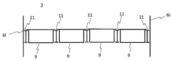
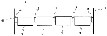
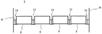
- FIG. 6 is a diagram showing an example of the fitting state in FIG. 5 viewed from a direction perpendicular to the paper surface as in FIG. 4.
- FIG. 8 is a view showing an example of the fitted state in FIG. 7 viewed from a direction perpendicular to the paper surface as in FIG. 4.
- a state in which the screen plate unit is fitted between the beams of the deformed H-shaped steel, which has two flanges and two webs and whose cross section has the shape of Roman numeral 2 is viewed from the viewpoint V of FIG. 4 along the plane of the paper.
- FIG. 10 is a view showing an example of the fitted state in FIG.
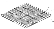
- FIG. 9 seen from a direction perpendicular to the paper surface as in FIG. 4. It is a figure which shows an example of a screen plate unit. It is a figure which shows an example of the beam installed in the reactor duct. It is a figure which shows an example of a screen plate. It is a perspective view which shows an example of the state which installed the screen plate in the reactor duct inlet side.
- FIG. 5 is a partial view showing an example of a state in which a screen plate unit is fitted between a beam composed of an H-shaped steel and a receiving member attached to a lower flange thereof, viewed from the viewpoint V of FIG. 4 along the paper surface.
- FIG. 16 The figure which shows the example which looked at the state which fitted the screen plate unit between the beam of H-shaped cross section which consists of a general H-shaped steel consisting of two flanges and one web along the paper surface from the viewpoint V of FIG. Is. It is a figure which shows an example which looked at the fitting state in FIG. 16 from the direction perpendicular
- FIG. 18 From the direction perpendicular
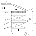
- FIG. 1 is a diagram showing a first embodiment of a denitration device according to the present invention.
- the denitration apparatus of the first embodiment has a denitration agent supply system and a reactor duct 6 having a flow path for flowing exhaust gas G from a boiler.
- the denitration agent supply system (not shown) supplies the denitration agent used for the reduction reaction of nitrogen oxides to the denitration device.
- Ammonia is preferably used as the denitration agent.
- the installation location if the position where the denitration agent is injected is upstream of the catalyst fixed bed 4, the installation location is not limited, and may be upstream of the screen plate 3 or the screen plate 3, for example. It may be downstream.
- a screen plate 3 and a fixed bed 4 containing a catalyst for removing nitrogen oxides contained in the exhaust gas are provided in this order along the flow of the exhaust gas.
- the screen plate is composed of a plurality of beams 11 provided on the inlet side in the reactor duct and a plurality of screen plate units 12, and the screen plate unit 12 is fitted between the beams. There is.
- FIG. 2 is a diagram showing a second embodiment of the denitration device according to the present invention.
- FIG. 3 is a diagram showing a third embodiment of the denitration device according to the present invention.
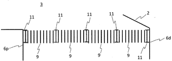
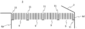
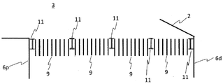
- FIG. 4 is a diagram showing a fourth embodiment of the denitration device according to the present invention.
- FIG. 21 is a diagram showing a fifth embodiment of the denitration device according to the present invention.
- the denitration device of the embodiment has an inlet duct 1, a joint duct 2, a reactor duct 6, and an outlet duct 5. Exhaust gas G from the boiler flows in the order of the inlet duct 1, the joint duct 2, the reactor duct 6, and the outlet duct 5.
- the inlet duct 1 has a flow path for laterally flowing the exhaust gas from the boiler.
- the upper partition surface and the lower partition surface of the flow path of the inlet duct 1 are drawn as straight lines.
- the cross-sectional shape of the flow path of the inlet duct viewed from the gas flow direction may be rectangular, trapezoidal, circular, elliptical, or the like. Of these, a rectangle is preferable in terms of workability.
- the joint duct 2 has a flow passage that changes the flow of exhaust gas from the horizontal direction to the vertical direction.
- the joint duct shown in FIG. 2 changes the flow downward, but may change the flow upward as in the denitration apparatus of the third embodiment shown in FIG.
- the orientation of the joint duct can be appropriately selected in consideration of the installation space and layout of the denitration device.
- the upper partition surface and the lower partition surface of the flow path of the joint duct 2 are drawn as straight lines.
- the upper partition surface and the lower partition surface of the flow path of the joint duct 2 may be arcuate when viewed from the same viewpoint as in FIG.
- the surface of the inlet duct 1 that partitions the lower side of the flow path and the surface of the reaction duct 6 that partitions the proximal side of the inlet duct 1 are directly joined.
- the surface (the surface indicated by the diagonal lines) that partitions the lower side of the flow path of the joint duct 2 may be omitted.
- the cross-sectional shape of the flow path of the joint duct 1 when viewed from the gas flow direction may be rectangular, trapezoidal, circular, elliptical, or the like. Of these, a rectangle is preferable in terms of workability.
- the reactor duct 6 has a flow path for flowing exhaust gas in the vertical direction.
- a surface 6p for partitioning the proximal side of the inlet duct and a surface 6d for partitioning the distal side of the inlet duct are drawn as straight lines.
- the cross-sectional shape of the flow path of the reactor duct viewed from the gas flow direction may be rectangular, trapezoidal, circular, elliptical, or the like. Of these, a rectangle is preferable in terms of workability.
- the size of the flow passage cross section of the reactor duct is preferably approximately the same from the inlet of the reactor duct to the outlet of the reactor duct through the outlet of the fixed catalyst bed.
- the outlet of the reactor duct is usually connected to the inlet of the outlet duct 5.
- a screen plate 3 and a catalyst fixed bed 4 are provided in the reactor duct.
- the screen plate 3 is provided on the inlet side of the reactor duct.
- the catalyst fixed bed 4 is provided on the outlet side of the reactor duct.
- the screen plate 3 comprises a plurality of beams 11 and a plurality of screen plate units 12 provided on the inlet side in the reactor duct.
- the screen plate unit 12 includes a plurality of rectangular blade members 9 arranged at predetermined intervals so that the main surfaces thereof are parallel to each other, and each blade member so as to be perpendicular to the main surface of each blade member. It is preferable to form a slit lattice composed of the cross member 10 joined to the long side of the. As shown in FIG. 11, an end member 8 joined to the short side of each blade member so as to be perpendicular to the main surface of each blade member 9 may be further provided.
- the right angle here is not limited to 90 degrees, and includes an angle that exhibits an action equivalent to the right angle in practical use.
- the main surface of the blade member 9 intersects the gas flow direction in the inlet duct 1 substantially at right angles and is substantially parallel to the gas flow direction in the reactor duct 6. It is preferable to install the unit 12 (see FIG. 14).
- the beam 11 is passed at two inlet inner walls at the inlet of the flow path of the reactor duct 6, for example, parallel or at right angles to the gas flow direction in the inlet duct 1, or in a grid. It is what is done.
- Each beam has a box-shaped, H-shaped, or T-shaped or inverted T-shaped cross-section.
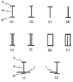
- a tetrahedral box column as shown in FIG. 20(g) or an H-shaped steel stiffened by a flat plate as shown in FIG. 20(h) can be used.
- a beam having an H-shaped cross section has a general H-section steel consisting of two flanges of the same width and one web as shown in FIG. 20(a), and a flange 2 of the same width as shown in FIG. 20(e). It is possible to use a deformed H-shaped steel or the like in which the cross section composed of one sheet and two webs is shaped like Roman numeral 2.
- T-shaped steel As shown in FIG. 20(c) or (d) can be used.
- the beam is a deformed H-section steel consisting of one wide flange, one narrow flange and one web as shown in Fig. 20(b), and one wide flange as shown in Fig. 20(f).
- a deformed H-section steel consisting of one width flange and two webs can be used.
- the flange r of the above-mentioned shaped steel as shown in FIGS. 20(i) and (j) is provided with a supporting member r protruding in the width direction longer than the flange, and the screen plate unit is supported by the supporting member.
- a beam that can be used can be used.
- an eddy current prevention member 13 may be provided below each beam. Thereby, the gas flow can be made more uniform.
- the eddy current prevention member 13 is not particularly limited in size, installation direction, etc. as long as it has a shape capable of preventing eddy currents.
- a strip-shaped member having an inverted triangular cross section is provided below the beam like a curtain.
- the strip-shaped member having an inverted triangular cross section may be formed by bending a flat plate into a V shape as shown in FIG.
- the height of the beam may be the same as the thickness of the screen plate unit, or may be different from the thickness of the screen plate unit as shown in FIGS. 16 to 19.
- the width of the beam is not particularly limited as long as it does not fall off when the screen plate unit 12 is fitted.
- the type of beam may be the same in the vertical and horizontal directions of the grating, or the type of beam may be different in the vertical and horizontal directions of the grating.
- the screen plate unit 12 is fitted between the beams.
- the screen plate unit 12 may have a collar 8b on all or part of the outer edge.
- the screen plate unit 12 is supported by hanging the outer edge of the screen plate unit 12 or the flange 8b on the protruding portion of the beam 11.
- the flange 8b is installed by using an end member having an L-shaped cross section, but the flange member may be installed by welding the blade member or the end member. .. If the protrusion on the beam side is sufficiently large, it can be supported by the outer edge of the screen plate unit 12, and in that case, the collar 8b is not necessary (see FIGS. 15 and 18).
- the collar 8b may be installed on the upper side of the screen plate unit as shown in FIG. 5, or may be installed on the lower side of the screen plate unit as shown in FIG. 6 or 7. Further, as shown in FIG. 15, a receiving member for the screen plate unit may be installed on the beam side.
- the beam parallel to the main surface of the blade member has the same rectification effect as that of the blade member, as shown in FIG. 6, FIG. 8, FIG. 10, FIG. 17 or FIG.
- the beam perpendicular to the main surface of the blade member may flow to the left and right of the main surface of the blade member, so as shown in FIG. 5, FIG. 7, FIG. 9, FIG. 16 or FIG. It is preferable to reduce the gap between the unit and the screen plate unit by abutting the edge or the brim of the unit, and it is more preferable to make the gap equal to or smaller than the gap between the main surfaces of the blade members.
- the height of the blade member provided in the screen plate unit closest to the inlet duct gradually increases from the side closer to the inlet duct to the side farther from the inlet duct.
- the upper end portion of the blade member of the next row projects from the upper end of the blade member of the front row, The gas, which has passed through the upper end without hitting, hits the upper end of the blade member in the next row.
- the amount of gas hitting the blade members in the rear row increases, and a more uniform flow is likely to occur.
- the nitrogen oxide uniformly contacts the catalyst fixed bed with the denitration agent, so that the reaction rate in the catalyst fixed bed can be increased. Further, since the dust contained in the combustion exhaust gas uniformly contacts the catalyst fixed bed, it prevents local wear of the catalyst fixed bed or local accumulation of dust on the catalyst fixed bed, and suppresses local deterioration of the catalyst. be able to.
Landscapes
- Engineering & Computer Science (AREA)
- Mechanical Engineering (AREA)
- General Engineering & Computer Science (AREA)
- Exhaust Gas Treatment By Means Of Catalyst (AREA)
- Chimneys And Flues (AREA)
Abstract
脱硝剤供給システム、およびボイラからの排ガスを流す流路を有する反応器ダクトを有し、反応器ダクト内に、スクリーンプレートおよび触媒固定床を、排ガスの流れに沿ってこの順で有し、スクリーンプレートは、反応器ダクト内の入口側に設けられた複数のビームと複数のスクリーンプレートユニットとから成り、且つスクリーンプレートユニットがビームとビームとの間に嵌っている、脱硝装置。
Description
本発明は、脱硝装置に関する。
燃焼排ガスに含まれる窒素酸化物の除去に用いられる装置が種々提案されている。
例えば、特許文献1は、排ガスが流入する入口ダクトと排ガス浄化触媒を配置した触媒ダクトがベンド部で接続することにより構成され、かつ触媒ダクト入口の断面方向に高さAの整流格子を配置した排ガス処理装置において、整流格子を支持するために整流格子上面と同一位置になるように配置した高さBの整流格子外枠と、該整流格子外枠を支持するため、該整流格子と平行に設置された整流格子支持梁とを備え、前記高さAが前記高さBより小さく構成されていることを特徴とする整流装置を有する排ガス処理装置を開示している。
例えば、特許文献1は、排ガスが流入する入口ダクトと排ガス浄化触媒を配置した触媒ダクトがベンド部で接続することにより構成され、かつ触媒ダクト入口の断面方向に高さAの整流格子を配置した排ガス処理装置において、整流格子を支持するために整流格子上面と同一位置になるように配置した高さBの整流格子外枠と、該整流格子外枠を支持するため、該整流格子と平行に設置された整流格子支持梁とを備え、前記高さAが前記高さBより小さく構成されていることを特徴とする整流装置を有する排ガス処理装置を開示している。
特許文献2は、排ガスが流動する排ガス通路と、前記排ガス通路に設置された整流兼脱硝触媒層と、前記排ガス通路の前記整流兼脱硝触媒層よりも排ガスの流れ方向下流側に配置された少なくとも1層の脱硝触媒層と、を有し、前記整流兼脱硝触媒層は、前記排ガスの流れ方向における長さが、前記脱硝触媒層よりも短いことを特徴とする脱硝設備を開示している。この整流兼脱硝触媒層は、板状触媒と、板状触媒を垂直煙道部に固定する支持機構とを有すると、特許文献2は述べている。
特許文献3は、脱硝装置において触媒層の上流側にガス流れ方向に複数個の金網を設けてなることを特徴とする触媒摩耗防止装置を開示している。該装置では、金網取付用支持山形鋼を排ガスダクトに設置し、その上に金網を載置している。金網を排ガスが通過するとき、偏流、渦流等を整流するようである。
特許文献4は、上下方向に多数のガスの通路を有する柱状の触媒を、ボイラ排ガスダクト内に設けた所要数のパッケージボックス内に、相互の側部を隣接せしめて一体に充填してなる触媒反応装置において、前記パッケージボックスの床面に、上部を凹凸状に形成した細長い板状の支持梁を配設し、該支持梁の凸部を用いて前記触媒を支持せしめるよう構成したことを特徴とする触媒反応装置を開示している。
特許文献5は、触媒バスケットを囲繞する側壁の適宜箇所にガイド部材を設けると共に該ガイド部材を介し、触媒バスケットを嵌合させ固定するようにしたことを特徴とする排煙脱硝反応装置を開示している。該装置は、排ガスが均一に流れるように整流するガス整流装置を載置する上流側受梁と触媒バスケットを載置する下流側受梁とをそれぞれ備えている。
本発明の課題は、新規な脱硝装置を提供することである。
本発明は以下の態様を包含する。
〔1〕 脱硝剤供給システム、およびボイラからの排ガスを流す流路を有する反応器ダクトを有し、
反応器ダクト内に、スクリーンプレートおよび触媒固定床を、排ガスの流れに沿ってこの順で有し、
スクリーンプレートは、反応器ダクト内の入口側に設けられた複数のビームと複数のスクリーンプレートユニットとから成り、且つスクリーンプレートユニットがビームとビームとの間に嵌っている、
脱硝装置。
反応器ダクト内に、スクリーンプレートおよび触媒固定床を、排ガスの流れに沿ってこの順で有し、
スクリーンプレートは、反応器ダクト内の入口側に設けられた複数のビームと複数のスクリーンプレートユニットとから成り、且つスクリーンプレートユニットがビームとビームとの間に嵌っている、
脱硝装置。
〔2〕 脱硝剤供給システム、ボイラからの排ガスを横方向に流す流路を有する入口ダクト、排ガスの流れを横方向から縦方向に変える流路を有する継手ダクト、および排ガスを縦方向に流す流路を有する反応器ダクトを有し、
反応器ダクト内に、スクリーンプレートおよび触媒固定床を、排ガスの流れに沿ってこの順で有し、
スクリーンプレートは、反応器ダクト内の入口側に設けられた複数のビームと複数のスクリーンプレートユニットとから成り、且つスクリーンプレートユニットがビームとビームとの間に嵌っている、
脱硝装置。
反応器ダクト内に、スクリーンプレートおよび触媒固定床を、排ガスの流れに沿ってこの順で有し、
スクリーンプレートは、反応器ダクト内の入口側に設けられた複数のビームと複数のスクリーンプレートユニットとから成り、且つスクリーンプレートユニットがビームとビームとの間に嵌っている、
脱硝装置。
〔3〕 スクリーンプレートユニットは、主面が相互に平行となるように所定の間隔をあけて配列した複数の矩形羽板部材、および各羽板部材の主面に直角になるように各羽板部材の長辺に接合されたクロス部材からなるスリット格子構造を成している、〔1〕または〔2〕に記載の脱硝装置。
〔4〕 スクリーンプレートは、各羽板部材の主面に直角になるように各羽板部材の短辺に接合されたエンド部材をさらに有する、〔3〕に記載の脱硝装置。
〔5〕 エンド部材は断面がL字形状を成している、〔4〕に記載の脱硝装置。
〔6〕 スクリーンプレートユニットは、外縁の一部または全部に、鍔を有する、〔1〕~〔5〕のいずれかひとつに記載の脱硝装置。
〔4〕 スクリーンプレートは、各羽板部材の主面に直角になるように各羽板部材の短辺に接合されたエンド部材をさらに有する、〔3〕に記載の脱硝装置。
〔5〕 エンド部材は断面がL字形状を成している、〔4〕に記載の脱硝装置。
〔6〕 スクリーンプレートユニットは、外縁の一部または全部に、鍔を有する、〔1〕~〔5〕のいずれかひとつに記載の脱硝装置。
〔7〕 各ビームは、断面が四角形状、H字形状、またはT字若しくは逆T形状を成している、請求項〔1〕~〔6〕に記載の脱硝装置。
〔8〕 各ビームは、広幅フランジと狭幅フランジとウェブとからなる変形H形鋼からなり、スクリーンプレートユニットが広幅フランジによって受け支えられている、〔1〕~〔3〕のいずれかひとつに記載の脱硝装置。
〔9〕 各ビームは、その下部に幅方向にフランジよりも長く突き出した受材が設置されていて、スクリーンプレートユニットが受材によって受け支えられている、〔1〕~〔3〕のいずれかひとつに記載の脱硝装置。
〔8〕 各ビームは、広幅フランジと狭幅フランジとウェブとからなる変形H形鋼からなり、スクリーンプレートユニットが広幅フランジによって受け支えられている、〔1〕~〔3〕のいずれかひとつに記載の脱硝装置。
〔9〕 各ビームは、その下部に幅方向にフランジよりも長く突き出した受材が設置されていて、スクリーンプレートユニットが受材によって受け支えられている、〔1〕~〔3〕のいずれかひとつに記載の脱硝装置。
本発明の脱硝装置は、排ガスと脱硝剤とを均一に混合でき、且つ固定床に導入される排ガスの流れに偏りが生じ難いので、脱硝効率が極めて高い。本発明の脱硝装置は、固定床の閉塞および固定床の偏摩耗が生じ難く、長期間の安定した運用が可能である。
本発明の脱硝装置は、従来技術に記載の脱硝装置に比べ、圧損が低いので、ファン駆動力を低減でき、ランニングコストを抑制できる。また、脱硝効率が高いので、触媒量を低減でき、初期コストを削減できる。さらに、ビームとスクリーンプレートユニットとが一体化するので、スクリーンプレートと触媒層との間の距離を短くすることができ、脱硝装置をコンパクトに、すなわち初期コストを低減することができる。
本発明の脱硝装置は、従来技術に記載の脱硝装置に比べ、圧損が低いので、ファン駆動力を低減でき、ランニングコストを抑制できる。また、脱硝効率が高いので、触媒量を低減でき、初期コストを削減できる。さらに、ビームとスクリーンプレートユニットとが一体化するので、スクリーンプレートと触媒層との間の距離を短くすることができ、脱硝装置をコンパクトに、すなわち初期コストを低減することができる。
本発明の実施形態を図面に基づいて具体的に説明する。なお、以下の実施形態によって本発明の範囲は制限されない。
図1は、本発明に係る脱硝装置の第一実施形態を示す図である。第一実施形態の脱硝装置は、脱硝剤供給システム、およびボイラからの排ガスGを流す流路を有する反応器ダクト6を有する。脱硝剤供給システム(図示せず)は、窒素酸化物の還元反応に使用される脱硝剤を脱硝装置に供給するものである。脱硝剤としてはアンモニアが好ましく用いられる。脱硝剤供給システムは、脱硝剤の注入される位置が触媒固定床4の上流であれば、その設置場所は制限されず、例えば、スクリーンプレート3の上流であってもよいし、スクリーンプレート3の下流であってもよい。
反応器ダクト内には、スクリーンプレート3、および排ガスに含まれる窒素酸化物を除去するための触媒を含む固定床4を排ガスの流れに沿ってこの順で有する。そして、スクリーンプレートは、反応器ダクト内の入口側に設けられた複数のビーム(beams)11と複数のスクリーンプレートユニット12とから成り、且つスクリーンプレートユニット12がビームとビームとの間に嵌っている。
図2は、本発明に係る脱硝装置の第二実施形態を示す図である。図3は、本発明に係る脱硝装置の第三実施形態を示す図である。図4は、本発明に係る脱硝装置の第四実施形態を示す図である。図21は、本発明に係る脱硝装置の第五実施形態を示す図である。該実施形態の脱硝装置は、入口ダクト1、継手ダクト2、反応器ダクト6、および出口ダクト5を有する。ボイラからの排ガスGは、入口ダクト1、継手ダクト2、反応器ダクト6、および出口ダクト5の順に流れる。
前記実施形態の脱硝装置において、入口ダクト1は、ボイラからの排ガスを横方向に流す流路を有する。図2においては、入口ダクト1の流路の、上側を仕切る面と下側を仕切る面とを直線で描いている。ガス流れ方向から見た入口ダクトの流路の断面形状は、矩形、台形、円形、楕円形などであることができる。これらのうち、加工のしやすさの点で矩形が好ましい。
前記実施形態の脱硝装置において、継手ダクト2は、排ガスの流れを横方向から縦方向に変える流路を有する。図2に示す継手ダクトは、下向きに流れを変えるものであるが、図3に示す第三実施形態の脱硝装置のように上向きに流れを変えるものであってもよい。継手ダクトの向きは、脱硝装置の設置スペースやレイアウトを考慮して適宜に選択できる。図2においては、継手ダクト2の流路の、上側を仕切る面と下側を仕切る面とを直線で描いている。継手ダクト2の流路の、上側を仕切る面と下側を仕切る面は、図2と同じ視点から見た場合に、弧を描くものであってもよい。
図4に示す第四実施形態の脱硝装置のように、入口ダクト1の流路の下側を仕切る面と反応ダクト6の流路の入口ダクト1の近位側を仕切る面とが直接に接合されて、継手ダクト2の流路の下側を仕切る面(斜線で示される面)が省略されていてもよい。ガス流れ方向から見た継手ダクト1の流路の断面形状が、矩形、台形、円形、楕円形などであることができる。これらのうち、加工のしやすさの点で矩形が好ましい。
前記実施形態の脱硝装置において、反応器ダクト6は、排ガスを縦方向に流す流路を有する。反応器ダクト6の流路の、入口ダクトの近位側を仕切る面6pと入口ダクトの遠位側を仕切る面6dを直線で描いている。ガス流れ方向から見た反応器ダクトの流路の断面形状は、矩形、台形、円形、楕円形などであることができる。これらのうち、加工のしやすさの点で矩形が好ましい。反応器ダクトの流路断面の大きさは、反応器ダクトの入口から触媒固定床の出口を経て反応器ダクトの出口まで、ほぼ同じであることが好ましい。反応器ダクトの出口は、通常、出口ダクト5の入口に接続されている。
反応器ダクト内には、スクリーンプレート3、および触媒固定床4が、設けられている。スクリーンプレート3は、反応器ダクトの入口側に設けられる。触媒固定床4は、反応器ダクトの出口側に設けられる。
スクリーンプレート3は、反応器ダクト内の入口側に設けられた複数のビーム11と複数のスクリーンプレートユニット12とから成る。
スクリーンプレートユニット12は、主面が相互に平行となるように所定の間隔をあけて配列した複数の矩形羽板部材9、および各羽板部材の主面に直角になるように各羽板部材の長辺に接合されたクロス部材10からなるスリット格子を成していることが好ましい。図11に示すように、各羽板部材9の主面に直角になるように各羽板部材の短辺に接合されたエンド部材8をさらに有してよい。なお、ここでの直角は、90度だけに限定されず、実用上、直角と同等の作用を呈する角度を包含する。
スクリーンプレートユニット12は、主面が相互に平行となるように所定の間隔をあけて配列した複数の矩形羽板部材9、および各羽板部材の主面に直角になるように各羽板部材の長辺に接合されたクロス部材10からなるスリット格子を成していることが好ましい。図11に示すように、各羽板部材9の主面に直角になるように各羽板部材の短辺に接合されたエンド部材8をさらに有してよい。なお、ここでの直角は、90度だけに限定されず、実用上、直角と同等の作用を呈する角度を包含する。
スクリーンプレートにおいては、羽板部材9の主面が入口ダクト1におけるガス流れ方向に実質的に直角に交わるように且つ反応器ダクト6におけるガス流れ方向に実質的に平行となるように、スクリーンプレートユニット12を設置することが好ましい(図14参照)。
ビーム11は、図12に示すように、反応器ダクト6の流路の入口において、対向する2つの内壁に、例えば、入口ダクト1におけるガス流れ方向に対して平行に若しくは直角にまたは格子に渡されるものである。
各ビームは、断面が、ボックス形状、H字形状、またはT字若しくは逆T字形状を成している。断面ボックス形状のビームには、図20(g)に示すような四面ボックス柱や図20(h)に示すような平板で補剛されたH形鋼などを用いることができる。断面H字形状のビームには、図20(a)に示すような同じ幅のフランジ2枚とウェブ1枚とからなる一般H形鋼、図20(e)に示すような同じ幅のフランジ2枚とウェブ2枚とからなる断面がローマ数字の2のような形をした変形H形鋼などを用いることができる。断面T字若しくは逆T字形状のビームには、図20(c)若しくは(d)に示すようなT形鋼などを用いることができる。ビームには、図20(b)に示すような広幅フランジ1枚と狭幅フランジ1枚とウェブ1枚とからなる変形H形鋼、図20(f)に示すような広幅フランジ1枚と狭幅フランジ1枚とウェブ2枚とからなる変形H形鋼などを用いることができる。また、図20(i)および(j)に示すような前述の形鋼のフランジに幅方向にフランジよりも長く突き出した受材rが設置されていて、スクリーンプレートユニットが受材によって受け支えることができるビームを用いることができる。
さらに、各ビームの下に渦流防止部材13を設けてもよい。これによりガス流れをより均一化できる。渦流防止部材13は渦流を防止できる形状をしておれば、その大きさ、設置向きなどにおいて特に制限されない。図9および10においては断面逆三角形の帯状部材をカーテンのようにビームの下に設けている。断面逆三角形の帯状部材は、図24のように平板をV字に折り曲げたものであってもよい。
ビームの高さは、スクリーンプレートユニットの厚さと同じであってもよいし、図16~19に示すようにスクリーンプレートユニットの厚さと異なる高さとしてもよい。ビームの幅は、スクリーンプレートユニット12をはめた時に脱落しない程度であれば特に限定されない。格子の縦横でビームの種類が同じであってもよいし、格子の縦横でビームの種類が異なっていてもよい。例えば、図18および図19に示す態様においては、一方が図20(b)に示す断面の変形H形鋼であり、もう一方が図20(a)に示す断面のH形鋼を用いている。
本発明においては、ビームとビームとの間に、スクリーンプレートユニット12が嵌っている。スクリーンプレートユニット12は、外縁の全部または一部に、鍔8bを有してもよい。スクリーンプレートユニット12の外縁または鍔8bをビーム11の出っ張り部に掛かることによってスクリーンプレートユニット12を支持する。図11に示すスクリーンプレートユニット12においては、鍔8bは、断面L字形状のエンド部材を用いることによって設置されているが、羽板部材またはエンド部材に鍔部材を溶接によって設置されていてもよい。ビーム側の出っ張りが十分に大きければ、スクリーンプレートユニット12の外縁にて支持することができるので、その場合には鍔8bは無くてもよい(図15、図18参照)。鍔8bは、図5に示すようにスクリーンプレートユニットの上側に設置されていてもよいし、図6または7に示すようにスクリーンプレートユニットの下側に設置されていてもよい。また、図15に示すようにビーム側にスクリーンプレートユニットの受材を設置してもよい。
羽板部材の主面に平行方向のビームは、羽板部材と同等の整流効果を奏するので、図6、図8、図10、図17または図19に示すように、スクリーンプレートユニットとの間に若干の隙間があってもよい。羽板部材の主面に直角方向のビームは、羽板部材の主面の左右に逃げる流れが生じるおそれがあるので、図5、図7、図9、図16または図18に示すように、ユニットの縁または鍔を当接して、スクリーンプレートユニットとの間の隙間を少なくすることが好ましく、その隙間を羽板部材の主面間の間隔と同じまたはそれより狭くすることがより好ましい。
第五実施形態の脱硝装置は、入口ダクトに最も近い側のスクリーンプレートユニットに設けられている羽板部材の高さが、入口ダクトに近い側から遠い側に向かって徐々に高くなっている以外は第四実施形態と同じである。図22および23に示すように、入口ダクトに最も近い側のスクリーンプレートユニットにおいては、前列の羽板部材の上端から次列の羽板部材の上端部が突き出ており、前列の羽板部材にぶつからずに上端を擦り抜けたガスが次列の羽板部材の上端部にぶつかる。第四実施形態に比べ、後列の羽板部材にぶつかるガスが増え、より均一な流れを生じさせやすい。
本発明の脱硝装置においては、窒素酸化物が触媒固定床に脱硝剤とともに均一に接触するので触媒固定床における反応率を高めることができる。また、燃焼排ガスに含まれるダストが触媒固定床に均一に接触するので触媒固定床の局所的な摩耗若しくは触媒固定床へのダストの局所的堆積を防いで、触媒の局所的な劣化を抑制することができる。
1:入口ダクト
2:継手ダクト
3:スクリーンプレート
4:触媒固定床
5:出口ダクト
6:反応器ダクト
7:脱硝剤(NH3)供給システム
8:エンド部材
9:羽板部材
10:クロス部材
11:ビーム
12:スクリーンプレートユニット
13:渦流防止部材
G:排ガス
fl:フランジ
w:ウェブ
r:受材
2:継手ダクト
3:スクリーンプレート
4:触媒固定床
5:出口ダクト
6:反応器ダクト
7:脱硝剤(NH3)供給システム
8:エンド部材
9:羽板部材
10:クロス部材
11:ビーム
12:スクリーンプレートユニット
13:渦流防止部材
G:排ガス
fl:フランジ
w:ウェブ
r:受材
Claims (9)
- 脱硝剤供給システム、およびボイラからの排ガスを流す流路を有する反応器ダクトを有し、
反応器ダクト内に、スクリーンプレートおよび触媒固定床を、排ガスの流れに沿ってこの順で有し、
スクリーンプレートは、反応器ダクト内の入口側に設けられた複数のビームと複数のスクリーンプレートユニットとから成り、且つスクリーンプレートユニットがビームとビームとの間に嵌っている、
脱硝装置。 - 脱硝剤供給システム、ボイラからの排ガスを横方向に流す流路を有する入口ダクト、排ガスの流れを横方向から縦方向に変える流路を有する継手ダクト、および排ガスを縦方向に流す流路を有する反応器ダクトを有し、
反応器ダクト内に、スクリーンプレートおよび触媒固定床を、排ガスの流れに沿ってこの順で有し、
スクリーンプレートは、反応器ダクト内の入口側に設けられた複数のビームと複数のスクリーンプレートユニットとから成り、且つスクリーンプレートユニットがビームとビームとの間に嵌っている、
脱硝装置。 - スクリーンプレートユニットは、主面が相互に平行となるように所定の間隔をあけて配列した複数の矩形羽板部材、および各羽板部材の主面に直角になるように各羽板部材の長辺に接合されたクロス部材からなるスリット格子構造を成している、請求項1または2に記載の脱硝装置。
- スクリーンプレートユニットは、各羽板部材の主面に直角になるように各羽板部材の短辺に接合されたエンド部材をさらに有する、請求項3に記載の脱硝装置。
- エンド部材は断面がL字形状を成している、請求項4に記載の脱硝装置。
- スクリーンプレートユニットは、外縁の全部または一部に、鍔を有する、請求項1~5のいずれかひとつに記載の脱硝装置。
- 各ビームは、断面が四角形状、H字形状、またはT字若しくは逆T字形状を成している、請求項1~6に記載の脱硝装置。
- 各ビームは、広幅フランジと狭幅フランジとウェブとからなる変形H形鋼からなり、スクリーンプレートユニットが広幅フランジによって受け支えられている、請求項1~3のいずれかひとつに記載の脱硝装置。
- 各ビームはそれに幅方向にフランジよりも長く突き出した受材が設置されていて、スクリーンプレートユニットが受材によって受け支えられている、請求項1~3のいずれかひとつに記載の脱硝装置。
Applications Claiming Priority (2)
| Application Number | Priority Date | Filing Date | Title |
|---|---|---|---|
| JP2019029292A JP2020134047A (ja) | 2019-02-21 | 2019-02-21 | 脱硝装置 |
| JP2019-029292 | 2019-02-21 |
Publications (1)
| Publication Number | Publication Date |
|---|---|
| WO2020171200A1 true WO2020171200A1 (ja) | 2020-08-27 |
Family
ID=72144940
Family Applications (1)
| Application Number | Title | Priority Date | Filing Date |
|---|---|---|---|
| PCT/JP2020/007004 Ceased WO2020171200A1 (ja) | 2019-02-21 | 2020-02-21 | 脱硝装置 |
Country Status (3)
| Country | Link |
|---|---|
| JP (1) | JP2020134047A (ja) |
| TW (1) | TW202039056A (ja) |
| WO (1) | WO2020171200A1 (ja) |
Families Citing this family (2)
| Publication number | Priority date | Publication date | Assignee | Title |
|---|---|---|---|---|
| JP7262493B2 (ja) * | 2021-01-14 | 2023-04-21 | 三菱重工業株式会社 | 脱硝反応器 |
| JP7371142B2 (ja) * | 2022-01-14 | 2023-10-30 | 三菱重工業株式会社 | 脱硝装置及びボイラ並びに脱硝装置の設置方法 |
Citations (7)
| Publication number | Priority date | Publication date | Assignee | Title |
|---|---|---|---|---|
| JPS62130723U (ja) * | 1986-02-10 | 1987-08-18 | ||
| JPS62191026A (ja) * | 1986-02-15 | 1987-08-21 | Babcock Hitachi Kk | 脱硝装置 |
| JP2003164729A (ja) * | 2001-11-29 | 2003-06-10 | Mitsubishi Heavy Ind Ltd | 浄化装置および浄化方法 |
| CN202078856U (zh) * | 2011-05-25 | 2011-12-21 | 上海龙净环保科技工程有限公司 | 模块化scr脱硝整流格栅装置 |
| CN203598693U (zh) * | 2013-11-27 | 2014-05-21 | 浙江蓝天求是环保股份有限公司 | 一种用于scr脱硝装置的楔形渐变式整流格栅 |
| CN206082179U (zh) * | 2016-07-28 | 2017-04-12 | 浙江融智能源科技有限公司 | 一种scr脱硝反应器入口阵列式流线型导流装置 |
| CN206508804U (zh) * | 2016-12-29 | 2017-09-22 | 大唐环境产业集团股份有限公司 | 一种新型scr脱硝反应器整流装置 |
-
2019
- 2019-02-21 JP JP2019029292A patent/JP2020134047A/ja active Pending
-
2020
- 2020-02-21 WO PCT/JP2020/007004 patent/WO2020171200A1/ja not_active Ceased
- 2020-02-21 TW TW109105596A patent/TW202039056A/zh unknown
Patent Citations (7)
| Publication number | Priority date | Publication date | Assignee | Title |
|---|---|---|---|---|
| JPS62130723U (ja) * | 1986-02-10 | 1987-08-18 | ||
| JPS62191026A (ja) * | 1986-02-15 | 1987-08-21 | Babcock Hitachi Kk | 脱硝装置 |
| JP2003164729A (ja) * | 2001-11-29 | 2003-06-10 | Mitsubishi Heavy Ind Ltd | 浄化装置および浄化方法 |
| CN202078856U (zh) * | 2011-05-25 | 2011-12-21 | 上海龙净环保科技工程有限公司 | 模块化scr脱硝整流格栅装置 |
| CN203598693U (zh) * | 2013-11-27 | 2014-05-21 | 浙江蓝天求是环保股份有限公司 | 一种用于scr脱硝装置的楔形渐变式整流格栅 |
| CN206082179U (zh) * | 2016-07-28 | 2017-04-12 | 浙江融智能源科技有限公司 | 一种scr脱硝反应器入口阵列式流线型导流装置 |
| CN206508804U (zh) * | 2016-12-29 | 2017-09-22 | 大唐环境产业集团股份有限公司 | 一种新型scr脱硝反应器整流装置 |
Also Published As
| Publication number | Publication date |
|---|---|
| JP2020134047A (ja) | 2020-08-31 |
| TW202039056A (zh) | 2020-11-01 |
Similar Documents
| Publication | Publication Date | Title |
|---|---|---|
| JP2637119B2 (ja) | 脱硝反応装置 | |
| JP7261019B2 (ja) | 脱硝装置 | |
| KR102017485B1 (ko) | 연도 가스 혼합 장치 | |
| JP2020134047A (ja) | 脱硝装置 | |
| US7383850B2 (en) | Reagent injection grid | |
| KR102491279B1 (ko) | 배가스 정화 장치 | |
| CN106984192B (zh) | 一种耦合scr脱硝导流装置及结构 | |
| JPH10165769A (ja) | 脱硝装置 | |
| KR102620035B1 (ko) | 배연 탈황 장치 | |
| JP2002048329A (ja) | 整流装置を有する排ガス処理装置 | |
| JP3207684B2 (ja) | アンモニアガス注入装置 | |
| CN101341549B (zh) | 适于压水核反应堆的燃料组件 | |
| US4581045A (en) | Gas distributing device | |
| JP5977055B2 (ja) | ガス整流装置、及び、該ガス整流装置を備えたバグフィルタ | |
| JP6915068B2 (ja) | 石炭焚きボイラ用脱硝装置 | |
| JP2005199184A (ja) | 排煙脱硫装置 | |
| JPH08168652A (ja) | 排ガス脱硝装置 | |
| JPH0881161A (ja) | エレベータ装置 | |
| TW201943461A (zh) | 熱交換器 | |
| JP7391651B2 (ja) | 脱硝装置及びボイラシステム並びに脱硝装置の設置方法 | |
| JP2003112015A (ja) | 脱硝反応装置 | |
| JP2655808B2 (ja) | パネル式充填材受け | |
| JP2004255324A (ja) | 排煙脱硝装置 | |
| JP6117329B2 (ja) | ガス整流装置、及び、該ガス整流装置を備えたバグフィルタ | |
| TW202600234A (zh) | 脫硝裝置 |
Legal Events
| Date | Code | Title | Description |
|---|---|---|---|
| 121 | Ep: the epo has been informed by wipo that ep was designated in this application |
Ref document number: 20759470 Country of ref document: EP Kind code of ref document: A1 |
|
| NENP | Non-entry into the national phase |
Ref country code: DE |
|
| 122 | Ep: pct application non-entry in european phase |
Ref document number: 20759470 Country of ref document: EP Kind code of ref document: A1 |