WO2020171185A1 - 鋼片の研削方法、棒鋼の製造方法及び線材の製造方法 - Google Patents
鋼片の研削方法、棒鋼の製造方法及び線材の製造方法 Download PDFInfo
- Publication number
- WO2020171185A1 WO2020171185A1 PCT/JP2020/006916 JP2020006916W WO2020171185A1 WO 2020171185 A1 WO2020171185 A1 WO 2020171185A1 JP 2020006916 W JP2020006916 W JP 2020006916W WO 2020171185 A1 WO2020171185 A1 WO 2020171185A1
- Authority
- WO
- WIPO (PCT)
- Prior art keywords
- grinding
- steel
- steel slab
- manufacturing
- corner
- Prior art date
- Legal status (The legal status is an assumption and is not a legal conclusion. Google has not performed a legal analysis and makes no representation as to the accuracy of the status listed.)
- Ceased
Links
Images




Classifications
-
- B—PERFORMING OPERATIONS; TRANSPORTING
- B21—MECHANICAL METAL-WORKING WITHOUT ESSENTIALLY REMOVING MATERIAL; PUNCHING METAL
- B21B—ROLLING OF METAL
- B21B1/00—Metal-rolling methods or mills for making semi-finished products of solid or profiled cross-section; Sequence of operations in milling trains; Layout of rolling-mill plant, e.g. grouping of stands; Succession of passes or of sectional pass alternations
- B21B1/16—Metal-rolling methods or mills for making semi-finished products of solid or profiled cross-section; Sequence of operations in milling trains; Layout of rolling-mill plant, e.g. grouping of stands; Succession of passes or of sectional pass alternations for rolling wire rods, bars, merchant bars, rounds wire or material of like small cross-section
-
- B—PERFORMING OPERATIONS; TRANSPORTING
- B24—GRINDING; POLISHING
- B24B—MACHINES, DEVICES, OR PROCESSES FOR GRINDING OR POLISHING; DRESSING OR CONDITIONING OF ABRADING SURFACES; FEEDING OF GRINDING, POLISHING, OR LAPPING AGENTS
- B24B27/00—Other grinding machines or devices
-
- B—PERFORMING OPERATIONS; TRANSPORTING
- B24—GRINDING; POLISHING
- B24B—MACHINES, DEVICES, OR PROCESSES FOR GRINDING OR POLISHING; DRESSING OR CONDITIONING OF ABRADING SURFACES; FEEDING OF GRINDING, POLISHING, OR LAPPING AGENTS
- B24B7/00—Machines or devices designed for grinding plane surfaces on work, including polishing plane glass surfaces; Accessories therefor
- B24B7/10—Single-purpose machines or devices
- B24B7/12—Single-purpose machines or devices for grinding travelling elongated stock, e.g. strip-shaped work
-
- B—PERFORMING OPERATIONS; TRANSPORTING
- B24—GRINDING; POLISHING
- B24B—MACHINES, DEVICES, OR PROCESSES FOR GRINDING OR POLISHING; DRESSING OR CONDITIONING OF ABRADING SURFACES; FEEDING OF GRINDING, POLISHING, OR LAPPING AGENTS
- B24B9/00—Machines or devices designed for grinding edges or bevels on work or for removing burrs; Accessories therefor
Definitions
- the present invention relates to a method for grinding a steel slab, a method for manufacturing a steel bar, and a method for manufacturing a wire rod.
- Patent Document 1 discloses a technique relating to a method for manufacturing a large diameter wire rod for cold forging, which has a high effect of suppressing the occurrence of bald defects.
- Patent Document 2 when manufacturing a large-diameter wire rod having a diameter of 20 mm or more by hot-rolling a square steel piece, a flaw detected by magnetic particle flaw detection and a flaw and rubbing not detected by magnetic particle flaw detection from the square steel piece. It is characterized by hot rolling after removing the flaws.
- Patent Document 2 since the scratches and scuff marks which are not detected by the magnetic particle flaw detection are present at the corners of the square steel piece, after chamfering all the corners along the longitudinal direction, hot rolling is performed.
- a method for manufacturing a diameter wire has also been proposed.
- the flaws may remain on the steel bar.
- a method of forcibly grinding the entire surface of the steel slab before rolling with a grinder is also implemented, but with this method, the time required for maintenance increases and the grinding amount Therefore, the productivity of the billet is reduced.
- Patent Document 2 when a square steel piece is rolled into a large-diameter wire rod having a diameter of 20 mm or more, it is assumed that the scratches and scuff marks present on the square steel piece cause a bald spot on the rolled wire rod. There is. However, even when rolled into a wire rod having a diameter of less than 20 mm, flaws may remain in the rolled steel bar or wire rod. In addition, even if the corners that are thought to have scratches or scratches are chamfered over the entire length, the presence of extremely small scratches is not recognized, and there is a high level of demand for flawlessness of consumers. In some cases, problems may remain in the occurrence of flaws in the steel bar and wire rod after rolling.
- An object of the present invention is to provide a method for grinding a steel slab, a method for manufacturing a steel bar and a method for manufacturing a wire rod, which are capable of further reducing surface defects while suppressing a decrease in productivity.
- the present inventors investigated the casting structure by observing the cross section of a steel bar obtained by rolling a steel slab with a microscope. Then, the inventors of the present invention identified a position where surface flaws (hereinafter, also referred to as surface flaws) were particularly likely to occur in the steel piece before rolling from the survey results. From this identification, it became clear that in the steel slab before rolling, many surface flaws were present in the corners of the steel slab and in the vicinity thereof. The present invention has been made based on such findings.
- the method for grinding a steel piece according to an aspect of the present invention the method of grinding the steel piece before rolling the steel piece that is long in one direction and has a rectangular cross-section taken along a plane orthogonal to the one direction. Grinding a region including a range of 26% or more and 30% or less of the length of one side of the rectangle from one side of the rectangle to one side of the rectangle over the entire length of the steel slab.
- a method for manufacturing a steel bar according to one aspect of the present invention includes a step of performing the method for grinding a steel piece described above, and a step of manufacturing a steel bar by rolling the steel piece whose region has been ground.
- a wire rod manufacturing method according to an aspect of the present invention includes a step of performing the above-described steel piece grinding method and a step of manufacturing a wire rod by rolling the steel piece whose region has been ground.
- FIG. 1 is a flowchart showing a method for grinding a steel slab according to an embodiment of the present invention.
- FIG. 2 is a diagram schematically showing each step of surface inspection and surface grinding of a steel slab according to the embodiment of the present invention.
- FIG. 3 is a diagram schematically showing a grinding method in the vicinity of a corner of a steel slab according to the embodiment of the present invention.
- FIG. 4 is a cross-sectional view showing the steel slab after the corner portions are ground.
- FIG. 5: is sectional drawing which shows the steel bar which concerns on embodiment of this invention.
- FIG. 6 is a sectional view showing a wire rod according to the embodiment of the present invention.
- FIG. 1 is a flowchart showing a method for grinding a steel slab according to an embodiment of the present invention.
- FIG. 2 is a diagram schematically showing each step of surface inspection and surface grinding of a steel slab according to the embodiment of the present invention.
- FIG. 3 is a diagram schematically showing a grinding method in the vicinity
- FIG. 7 is a graph showing the results of an examination of the relationship between the presence or absence of grinding in the vicinity of the corners and the incidence of defects in steel bars.
- FIG. 8 is a microstructure observation photograph of a C cross section of a steel bar product, where (a) shows the entire cross section and (b) shows the position where flaws occur.
- the positive side in the Z-axis direction may be referred to as “upper” and the negative side in the Z-axis direction may be referred to as “lower”.
- “Upper” and “lower” do not necessarily mean vertical to the ground. That is, the “up” and “down” directions are not limited to the gravity direction.
- “Upper” and “lower” are merely expedient expressions for specifying a relative positional relationship in a steel slab or the like described later, and do not limit the technical idea of the present invention. For example, if the paper surface is rotated 180 degrees, “upper” becomes “lower” and “lower” becomes “upper”.
- the directions may be described using the words of the X-axis direction, the Y-axis direction, and the Z-axis direction.
- the X-axis direction and the Y-axis direction are horizontal directions
- the Z-axis direction is the vertical direction.
- the X axis, the Y axis, and the Z axis are orthogonal to each other.
- the X axis, the Y axis, and the Z axis form a left-handed system, for example.
- the steel billet concerning the embodiment of the present invention is manufactured by continuous casting.
- a steel slab produced by continuous casting is long in one direction (hereinafter, also referred to as a longitudinal direction), and has flaws (that is, surface flaws) such as cracks and nonmetallic inclusions on its surface.
- flaws that is, surface flaws
- an oxygen gas for fusing is blown onto the surface of the billet to remove the entire surface of the billet. Is subjected to a fusing treatment with a thickness of, for example, about 2 mm.
- FIG. 1 is a flowchart showing a method for grinding a steel slab according to an embodiment of the present invention.
- FIG. 2 is a diagram schematically showing each step of surface inspection and surface grinding of a steel slab according to the embodiment of the present invention.
- the steel piece 2 subjected to the fusing treatment is moved by the conveying roller 3 to one side in the longitudinal direction of the steel piece 2 (for example, the arrow side in the X-axis direction). ) Is transported to.
- the steel slab 2 is a semi-finished product (that is, an unfinished product in the middle of the manufacturing process) before rolling, and is called a bloom or a billet depending on the use, shape and size.
- the steel ingot 2 is inspected for surface flaws by the surface inspection device 1 while being conveyed in the X-axis direction (step ST1 in FIG. 1).
- the surface inspection device 1 is, for example, a fluorescent magnetic particle flaw detector that detects surface flaws using fluorescent magnetic powder.
- the surface inspection device 1 detects a surface flaw or an unwelded portion remaining on the surface of the steel piece 2 after the ablation treatment, displays the detected position on the surface grinding device, and specifies a position with a flaw.
- the surface grinding device is identified as the above-described detected position on the surface of the steel piece 2, that is, a flaw.
- the surface is ground by bringing the grinder 4 into contact with the position. As a result, the surface grinding device removes the surface flaw and the unfused portion remaining on the steel slab 2 (step ST3 in FIG. 1).
- step ST2 in FIG. 1; No the surface grinding device does not bring the grinder 4 into contact with the surface of the steel piece 2. That is, the grinder 4 does not grind the surface of the steel slab 2.
- the grinding process proceeds to step ST4 of FIG. 1, and the surface grinding device operates the grinder 4 (see FIG. 3 described later) to grind the corner of the steel slab 2 and its vicinity (step of FIG. 1). ST4).
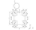
- FIG. 3 is a diagram schematically showing a method of grinding a corner of a steel slab and its vicinity according to an embodiment of the present invention.
- FIG. 3 shows a cross section of the steel piece 2 taken along a plane (eg, YZ plane) orthogonal to the longitudinal direction (eg, X-axis direction).
- the cross section of the steel piece 2 taken along the YZ plane has a rectangular shape.
- step ST4 of FIG. 1 the four corners of this rectangle and the parts in the vicinity thereof are ground.
- the corner and the portion in the vicinity thereof will be collectively referred to as the corner vicinity hereinafter.
- the vicinity of the corner to be ground is an area that extends from the corner of the rectangle to one side of the rectangle and ranges from 26% to 30% of the length of this side.
- a rectangle which is the cross-sectional shape of the steel piece 2
- the length of one side parallel to the width direction (for example, the Y-axis direction) of this rectangle is y
- the length of one side parallel to the thickness direction for example, the Z-axis direction
- the length in the Y-axis direction of the corner portion 21 including the corner portion 2A is y21
- the length of the corner portion 21 in the Z-axis direction is z21.
- the length y21 in the Y-axis direction of the corner portion 21 to be ground is 26% or more and 30% or less of the length y of one side parallel to the Y-axis direction of the rectangle.
- the length z21 in the Z-axis direction of the corner portion 21 to be ground is 26% or more and 30% or less of the length z of one side of the rectangle parallel to the Z-axis direction.
- the length in the Y-axis direction of the corner portion 22 including the corner portion 2B is y22
- the length of the corner portion 22 in the Z-axis direction is z22.
- the length y22 in the Y-axis direction of the corner portion 22 to be ground is 26% or more and 30% or less of the length y of one side parallel to the Y-axis direction of the rectangle.
- the length z22 in the Z-axis direction of the corner portion 22 to be ground is 26% or more and 30% or less of the length z of one side of the rectangle parallel to the Z-axis direction.
- the length in the Y-axis direction of the corner vicinity 23 including the corner 2C is y23, and the length of the corner vicinity 23 in the Z-axis direction is z23.
- the length y23 in the Y-axis direction of the corner portion 23 to be ground is 26% or more and 30% or less of the length y of one side of the rectangle parallel to the Y-axis direction.
- the length z23 in the Z-axis direction of the corner portion 23 to be ground is 26% or more and 30% or less of the length z of one side of the rectangle parallel to the Z-axis direction.
- the length in the Y-axis direction of the corner vicinity 24 including the corner 2D is y24, and the length of the corner vicinity 24 in the Z-axis direction is z24.
- the length y24 in the Y axis direction of the corner portion 24 to be ground is 26% or more and 30% or less of the length y of one side of the rectangle parallel to the Y axis direction.
- the length z24 in the Z-axis direction of the corner portion 24 to be ground is 26% or more and 30% or less of the length z of one side of the rectangle parallel to the Z-axis direction.
- Each of the four corners 2A, 2B, 2C, and 2D has a radius of curvature R.
- the radius of curvature R is 15 mm or more and 25 mm or less.
- Specific examples of the dimensions of the steel piece 2 and the corner portions 21, 22, 23, and 24 will be described.
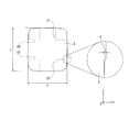
- FIG. 4 is a cross-sectional view showing the steel slab after the vicinity of the corner has been ground.
- the surfaces of the corner portions 21, 22, 23, and 24 are ground by the grinder 4.
- d is 1 mm or more and 3 mm or less, for example, 2 mm.
- the surfaces of the corner portions 21, 22, 23, 24 have a shape that is recessed from the periphery by a depth d as a trace of grinding. ..
- step ST5 of FIG. 1 for example, an operator visually checks the surfaces of the corner portions 21, 22, 23, and 24 to confirm whether or not there is uncut residue.
- the inspection device may visually inspect the surfaces of the corner portions 21, 22, 23, and 24 to confirm the presence or absence of uncut parts. If there is uncut material (step ST6; No), the process returns to step ST4. When there is no uncut residue (step ST6; Yes), the grinding process of the steel slab 2 shown in FIG. 1 is completed.
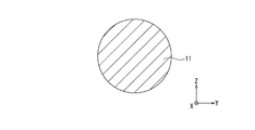
- FIG. 5 is a sectional view showing a steel bar according to an embodiment of the present invention.
- FIG. 6 is a sectional view showing a wire rod according to the embodiment of the present invention.
- the steel slab 2 that has completed the grinding process in FIG. 1 proceeds to the rolling process. In the rolling process, the billet 2 is rolled. As a result, a steel bar 11 as shown in FIG. 5 or a wire rod 12 as shown in FIG. 6 is manufactured from the steel piece 2.
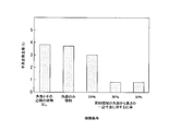
- FIG. 7 is a graph showing the results of an examination of the relationship between the presence/absence of grinding near the corners and the incidence of defects in steel bars.
- the data shown on the leftmost side in FIG. 7 is obtained when no grinding is performed near the corners.
- the second data from the left is the case where grinding is performed over the entire length of the steel slab only for the corner portion (only the rounded portion of the radius of curvature R).
- the three pieces of data on the right side are the cases where the entire length of the steel piece was ground from the corners to the length regions of 25%, 26%, and 30% of one side length of the steel piece.
- the vicinity of a corner portion over the entire length of the steel slab that is, a region including a range of 26% or more and 30% or less of one side length from the corner portion of the rectangle to one side of the rectangle is ground. Therefore, compared with the case where the corner and the vicinity thereof were not grounded at all (the leftmost data in FIG. 7) and the case where only the corner was grounded (the second data from the left in FIG. 7).
- the present inventor has confirmed that, in a steel bar manufactured from this billet, the incidence of defects due to surface defects is reduced.
- the grinding here is performed with a grinding depth of 1 mm.
- the occurrence rate of defects was confirmed by investigating the presence or absence of surface flaws in the steel bar 2 obtained by hot rolling a steel slab 2 (2000 pieces for each condition, 10000 pieces in total) that has undergone each grinding condition. It was The presence or absence of surface flaws was confirmed by observing the microstructure of the section C of the obtained steel bar with an optical microscope, and the case where there was a flaw with a depth of more than 0.050 mm on the surface of the steel bar was determined to be flawed (see FIG. 8 and FIG. An example in which there was a flaw with a depth of 0.076 mm), and the others were not flawed. Then, the defect occurrence rate for each 2000 grinding conditions was defined as the defect occurrence rate.
- FIG. 8 shows the structure of the C cross section of a steel bar product having a product diameter of 15 mm, which is obtained by grinding the surface at a position identified as having a flaw by a surface inspection with a grinder in the billet stage before rolling and then performing hot rolling. It is an observation photograph.
- This steel bar product was found to have flaws on the surface in the product stage after rolling.
- Fig. 8(a) shows the entire cross section of the steel bar product
- Fig. 8(b) shows the location of the flaw. The figure shows the case of observing at a higher magnification (200 times). For the flaw occurrence location as shown in FIG.
- the circumferential position in the steel bar product is specified, and when the structure observation result and the flaw occurrence location as shown in FIG. It is known that in the (before rolling) stage, flaws are generated at the positions corresponding to the corners. That is, it was found that the surface inspection of the steel slab could not detect flaws in the vicinity of the corners, and the grinding of a specific position based on the surface inspection result was insufficient in the vicinity of the corners. This finding is in good agreement with the result shown in FIG. 7 in which the defect occurrence rate was reduced by grinding the vicinity of the corner regardless of whether or not the defect was detected in the surface inspection.
- cutting is performed on a plane (eg, YZ plane) that is long in one direction (eg, X-axis direction) and is orthogonal to the one direction.
- a step of grinding the rectangular corner portions 21, 22, 23, 24 of the steel slab 2 over the entire length is provided. ..
- surface flaws such as small cracks are likely to occur on the surfaces of the corner portions 21, 22, 23, 24 of the steel slab 2 produced by continuous casting. As a cause of this, it is considered that fine internal cracks, segregation and the like are likely to occur in the corner portions 21, 22, 23 and 24 due to the oscillation marks generated on the surface of the steel slab 2 and the solidification form.
- the surfaces of the corners 21, 22, 23, 24 near the corners where surface flaws such as small cracks are particularly likely to occur are forced before the rolling of the steel slab 2.
- the surface flaw of the steel piece 2 can be further reduced.
- the method of grinding a steel piece according to the embodiment of the present invention can shorten the time required for grinding, as compared with a method of forcibly grinding the entire surface of the steel piece with a grinder in order to remove surface defects. Since the grinding amount can also be suppressed to a low level, it is possible to suppress a decrease in the productivity of the steel slab 2.
- the vicinity of the corner to be ground is an area that extends from the corner of the rectangle to one side of the rectangle and ranges from 26% to 30% of the length of this side. According to this, the surface flaw can be efficiently removed while suppressing the grinding amount of the steel piece 2 to be low.
- a large number of surface flaws remain in a range of 20 mm from each of the corners 2A, 2B, 2C, and 2D of the steel piece 2 by observing a cross section with a microscope.
- the surface flaws of the steel slab 2 can be efficiently removed.
- the surface near the corners is ground to a depth of 1 mm or more and 3 mm or less. According to this, since the surface flaw is often present in a range of 1 mm or more and 3 mm or less from the surface, the surface flaw can be removed while suppressing the grinding amount of the steel piece 2 to be low. Surface defects can be removed efficiently.
- a step of inspecting the surface of the steel slab 2 to identify a position having a surface flaw before the step of grinding the corner portions 21, 22, 23, 24. (For example, step ST1 of FIG. 1) and a step of removing the surface flaw by grinding the surface at the position where the surface of the steel piece 2 is identified as having a surface flaw (for example, step ST2, step ST3 of FIG. 1).
- step ST1 of FIG. 1 a step of removing the surface flaw by grinding the surface at the position where the surface of the steel piece 2 is identified as having a surface flaw.
- the surface flaws can be efficiently removed also on the surfaces other than the corner portions 21, 22, 23, 24.
- a method for manufacturing a steel bar according to an embodiment of the present invention is a step of performing the method for grinding a steel slab described above, and a steel slab 2 having corners 21, 22, 23, 24 ground is rolled to produce a steel bar 11. And a step of performing. According to this, since the surface flaws of the steel piece 2 are reduced, it is possible to reduce the occurrence of defects in the steel bar 11 made of the steel piece 2 due to the surface flaws.
- a wire rod manufacturing method according to an embodiment of the present invention is a step of performing the above-described steel slab grinding method, and a wire rod 12 is manufactured by rolling a steel slab 2 in which corner portions 21, 22, 23, 24 are ground. And a step of performing. According to this, since the surface flaws of the steel slab 2 are reduced, it is possible to reduce the occurrence of defects in the wire 12 made of the steel slab 2 due to the surface flaws.
Landscapes
- Engineering & Computer Science (AREA)
- Mechanical Engineering (AREA)
- Finish Polishing, Edge Sharpening, And Grinding By Specific Grinding Devices (AREA)
- Metal Rolling (AREA)
- Grinding Of Cylindrical And Plane Surfaces (AREA)
- Grinding And Polishing Of Tertiary Curved Surfaces And Surfaces With Complex Shapes (AREA)
Abstract
生産性の低下を抑制しつつ、表面の疵をさらに低減できるようにした鋼片の研削方法、棒鋼の製造方法及び線材の製造方法を提供する。鋼片の研削方法、棒鋼の製造方法及び線材の製造方法は、一方向に長く、且つ一方向と直交する平面で切断した断面の形状が矩形である鋼片を圧延する前に、矩形の角部から矩形の一辺に沿って該一辺の長さの26%以上30%以下までの範囲を含む領域を鋼片の全長にわたり研削する工程、を備える。
Description
本発明は、鋼片の研削方法、棒鋼の製造方法及び線材の製造方法に関する。
棒鋼製品の表面疵を低減する方法として、素材となる鋼片の表面を全面溶削し、表面検査装置にて表面疵を検出し、検出した表面疵をグラインダーで研削して除去する方法が知られている(例えば、特許文献1)。全面溶削からグラインダーによる表面疵を除去するまでの工程は、手入れとも呼ばれている。手入れが完了した鋼片は棒鋼に圧延される。また、特許文献2には、ヘゲ疵発生の抑止効果の高い冷間鍛造用太径線材の製造方法に関する技術が開示されている。この特許文献2の技術は、角鋼片を熱間圧延して直径20mm以上の太径線材を製造するに際し、角鋼片から、磁粉探傷で検出される疵、ならびに磁粉探傷では検出されない打ち疵および擦り疵を除去した後、熱間圧延することを特徴とするものである。ここで、特許文献2には、磁粉探傷では検出されない打ち疵や擦り疵は、角鋼片の角部に存在するので、角部をその長手方向に沿って全部面取りした後、熱間圧延する太径線材の製造方法についても提案されている。
上記のように、素材となる鋼片の全面溶削および表面疵の研削という手入れが完了した鋼片を用いた棒鋼であっても、棒鋼に疵が残る場合がある。疵の除去をより完全なものとするために、圧延前の鋼片の全表面をグラインダーで強制的に研削する方法も実施されているが、この方法では、手入れの所要時間が増え、研削量も増えるため、鋼片の生産性が低下してしまう。
また、特許文献2では、角鋼片を直径20mm以上の太径線材に圧延した場合に、角鋼片に存在した打ち疵および擦り疵が、圧延後の線材へのヘゲ疵発生の原因となるとしている。しかし、直径20mm未満の線材に圧延する場合についても、圧延後の棒鋼や線材に疵が残る場合があった。また、打ち疵や擦り疵が生じていると考えられる角部を全長にわたり面取りした場合であっても、極微小な疵の存在をも認めない等、需要家の無疵化に対する要求レベルが高い場合には、圧延後の棒鋼や線材の疵発生に課題が残る場合があった。
本発明は、生産性の低下を抑制しつつ、表面の疵をさらに低減できるようにした鋼片の研削方法、棒鋼の製造方法及び線材の製造方法を提供することを目的とする。
本発明者らは、鋼片を圧延して得られた棒鋼の断面を顕微鏡で観察して、鋳造組織の調査を行った。そして、本発明者らは、その調査結果から、圧延前の鋼片において、表面の疵(以下、表面疵ともいう)が特に発生しやすい位置を特定した。この特定により、圧延前の鋼片では、鋼片の角部およびその近傍に表面疵が多数存在していることが明らかとなった。本発明は、このような知見に基づいてなされたものである。
本発明の一態様に係る鋼片の研削方法は、一方向に長く、且つ前記一方向と直交する平面で切断した断面の形状が矩形である鋼片を圧延する前に、前記鋼片の前記矩形の角部から前記矩形の一辺に沿って該一辺の長さの26%以上30%以下までの範囲を含む領域を前記鋼片の全長にわたり研削する工程、を備える。
本発明の一態様に係る棒鋼の製造方法は、上記の鋼片の研削方法を行う工程と、前記領域が研削された鋼片を圧延して棒鋼を製造する工程と、を備える。
本発明の一態様に係る線材の製造方法は、上記の鋼片の研削方法を行う工程と、前記領域が研削された鋼片を圧延して線材を製造する工程と、を備える。
本発明の一態様に係る棒鋼の製造方法は、上記の鋼片の研削方法を行う工程と、前記領域が研削された鋼片を圧延して棒鋼を製造する工程と、を備える。
本発明の一態様に係る線材の製造方法は、上記の鋼片の研削方法を行う工程と、前記領域が研削された鋼片を圧延して線材を製造する工程と、を備える。
本発明の一態様によれば、生産性の低下を抑制しつつ、表面の疵をさらに低減できるようにした鋼片の研削方法、棒鋼の製造方法及び線材の製造方法を提供することができる。
以下に本発明の実施形態を説明する。以下の図面の記載において、同一又は類似の部分には同一又は類似の符号を付している。但し、図面は模式的なものであり、厚みと平面寸法との関係、各装置や各部材の厚みの比率等は現実のものとは異なることに留意すべきである。したがって、具体的な厚みや寸法は以下の説明を参酌して判定すべきものである。また、図面相互間においても互いの寸法の関係や比率が異なる部分が含まれていることは勿論である。
また、以下の説明では、Z軸方向の正側を「上」と称し、Z軸方向の負側を「下」と称する場合がある。「上」及び「下」は、必ずしも地面に対する鉛直方向を意味しない。つまり、「上」及び「下」の方向は、重力方向に限定されない。「上」及び「下」は、後述の鋼片等における相対的な位置関係を特定する便宜的な表現に過ぎず、本発明の技術的思想を限定するものではない。例えば、紙面を180度回転すれば「上」が「下」に、「下」が「上」になることは勿論である。
また、以下の説明では、X軸方向、Y軸方向及びZ軸方向の文言を用いて、方向を説明する場合がある。例えば、X軸方向及びY軸方向は水平方向であり、Z軸方向は鉛直方向である。X軸、Y軸及びZ軸は、互いに直交する。X軸、Y軸及びZ軸は、例えば、左手系をなす。
また、以下の説明では、X軸方向、Y軸方向及びZ軸方向の文言を用いて、方向を説明する場合がある。例えば、X軸方向及びY軸方向は水平方向であり、Z軸方向は鉛直方向である。X軸、Y軸及びZ軸は、互いに直交する。X軸、Y軸及びZ軸は、例えば、左手系をなす。
本発明の実施形態に係る鋼片は、連続鋳造によって製造される。連続鋳造によって製造された鋼片は、一方向(以下、長手方向ともいう)に長く、その表面には、割れや非金属介在物などの疵(すなわち、表面疵)が存在する。この表面疵を除去するために、本発明の実施形態では、まず、ホットスカーファーやコールドスカーファーなどの溶削設備を用い、溶削用酸素ガスを鋼片表面に吹き付けて鋼片表面の全面を、例えば2mm程度の厚みで溶削処理する。
溶削を行った後も、表面疵が溶削深さよりも深い場合には、表面疵が十分に除去されずに残存する。また、鋼片の溶削深さのばらつきが大きい場合は、未溶削部分が発生する場合もある。そこで、本発明の実施形態では、溶削処理が行われた鋼片について、表面検査と、表面検査の結果に基づく表面研削とを行う。
溶削を行った後も、表面疵が溶削深さよりも深い場合には、表面疵が十分に除去されずに残存する。また、鋼片の溶削深さのばらつきが大きい場合は、未溶削部分が発生する場合もある。そこで、本発明の実施形態では、溶削処理が行われた鋼片について、表面検査と、表面検査の結果に基づく表面研削とを行う。
図1は、本発明の実施形態に係る鋼片の研削方法を示すフローチャートである。図2は、本発明の実施形態に係る鋼片の表面検査及び表面研削の各工程を模式的に示す図である。本発明の実施形態では、図2に示すように、溶削処理が行われた鋼片2が、搬送ローラ3によって、鋼片2の長手方向の一方の側(例えば、X軸方向の矢印側)に搬送される。鋼片2は、圧延前の半製品(即ち、製造工程の途中にある未完成の製品)であり、用途や形状、大きさに応じて、ブルーム又はビレットと呼ばれる。鋼片2は、X軸方向に搬送されながら、表面検査装置1によって、表面疵の有無が検査される(図1のステップST1)。
表面検査装置1は、例えば、蛍光磁粉を用いて表面疵を探傷する蛍光磁粉探傷装置である。表面検査装置1は、溶削処理後の鋼片2の表面に残存する表面疵や未溶削部分を検出し、検出した位置を表面研削装置に表示させて、疵のある位置を特定する。表面疵や未溶削部分が検出された場合(図1のステップST2;Yes)、表面研削装置は、鋼片2の表面であって上記の検出した位置、すなわち、疵があると特定された位置にグラインダー4を接触させて、表面を研削する。これにより、表面研削装置は、鋼片2に残存する表面疵や未溶削部分を除去する(図1のステップST3)。
一方、表面疵や未溶削部分が検出されない場合(図1のステップST2;No)、表面研削装置は、鋼片2の表面にグラインダー4を接触させない。つまり、グラインダー4は、鋼片2の表面を研削しない。その際、研削処理は図1のステップST4へ進み、表面研削装置が、グラインダー4(後述の図3参照)を動作させて、鋼片2の角部およびその近傍を研削する(図1のステップST4)。
図3は、本発明の実施形態に係る鋼片の角部およびその近傍の研削方法を模式的に示す図である。図3は、鋼片2をその長手方向(例えば、X軸方向)と直交する面(例えば、Y-Z平面)で切断した断面を示している。図3に示すように、鋼片2をY-Z平面で切断した断面の形状は、矩形である。図1のステップST4では、この矩形の4つの角部と、その近傍の部位とを研削する。本発明の実施形態の説明では、以後、角部とその近傍の部位とを合わせて、角部近傍という。
研削される角部近傍は、矩形の角部から矩形の一辺に沿って、この一辺の長さの26%以上30%以下までの範囲を含む領域である。例えば、図3に示すように、鋼片2の断面形状である矩形は、4つの角部2A、2B、2C、2Dを有する。この矩形の幅方向(例えば、Y軸方向)に平行な一辺の長さをyとし、厚さ方向(例えば、Z軸方向)に平行な一辺の長さをzとする。また、角部2Aを含む角部近傍21のY軸方向の長さをy21とし、角部近傍21のZ軸方向の長さをz21とする。
研削される角部近傍21のY軸方向の長さy21は、矩形のY軸方向に平行な一辺の長さyの26%以上30%以下である。研削される角部近傍21のZ軸方向の長さz21は、矩形のZ軸方向に平行な一辺の長さzの26%以上30%以下である。
同様に、角部2Bを含む角部近傍22のY軸方向の長さをy22とし、角部近傍22のZ軸方向の長さをz22とする。研削される角部近傍22のY軸方向の長さy22は、矩形のY軸方向に平行な一辺の長さyの26%以上30%以下である。研削される角部近傍22のZ軸方向の長さz22は、矩形のZ軸方向に平行な一辺の長さzの26%以上30%以下である。
同様に、角部2Bを含む角部近傍22のY軸方向の長さをy22とし、角部近傍22のZ軸方向の長さをz22とする。研削される角部近傍22のY軸方向の長さy22は、矩形のY軸方向に平行な一辺の長さyの26%以上30%以下である。研削される角部近傍22のZ軸方向の長さz22は、矩形のZ軸方向に平行な一辺の長さzの26%以上30%以下である。
角部2Cを含む角部近傍23のY軸方向の長さをy23とし、角部近傍23のZ軸方向の長さをz23とする。研削される角部近傍23のY軸方向の長さy23は、矩形のY軸方向に平行な一辺の長さyの26%以上30%以下である。研削される角部近傍23のZ軸方向の長さz23は、矩形のZ軸方向に平行な一辺の長さzの26%以上30%以下である。
角部2Dを含む角部近傍24のY軸方向の長さをy24とし、角部近傍24のZ軸方向の長さをz24とする。研削される角部近傍24のY軸方向の長さy24は、矩形のY軸方向に平行な一辺の長さyの26%以上30%以下である。研削される角部近傍24のZ軸方向の長さz24は、矩形のZ軸方向に平行な一辺の長さzの26%以上30%以下である。
角部2Dを含む角部近傍24のY軸方向の長さをy24とし、角部近傍24のZ軸方向の長さをz24とする。研削される角部近傍24のY軸方向の長さy24は、矩形のY軸方向に平行な一辺の長さyの26%以上30%以下である。研削される角部近傍24のZ軸方向の長さz24は、矩形のZ軸方向に平行な一辺の長さzの26%以上30%以下である。
4つの角部2A、2B、2C、2Dは、曲率半径Rの丸みをそれぞれ有する。例えば、曲率半径Rは、15mm以上25mm以下である。
鋼片2及び角部近傍21、22、23、24の各寸法について、具体例を示す。鋼片2がビレットの場合、y=160mm、z=160mm、y21=y22=y23=y24=45mm、z21=z22=z23=z24=45mm、R=25mmである。鋼片2がブルームの場合、y=400mm、z=300mm、y21=y22=y23=y24=112mm、z21=z22=z23=z24=84mm、R=25mmである。なお、これらの寸法はあくまで一例であって、本発明の実施形態を限定するものではない。
鋼片2及び角部近傍21、22、23、24の各寸法について、具体例を示す。鋼片2がビレットの場合、y=160mm、z=160mm、y21=y22=y23=y24=45mm、z21=z22=z23=z24=45mm、R=25mmである。鋼片2がブルームの場合、y=400mm、z=300mm、y21=y22=y23=y24=112mm、z21=z22=z23=z24=84mm、R=25mmである。なお、これらの寸法はあくまで一例であって、本発明の実施形態を限定するものではない。
図4は、角部近傍が研削された後の鋼片を示す断面図である。図1のステップST4では、上記の角部近傍21、22、23、24の各表面がグラインダー4で研削される。図4に示すように、研削の深さをdとすると、dは1mm以上3mm以下であり、例えば2mmである。鋼片の角部近傍21、22、23、24が研削された後、角部近傍21、22、23、24の表面は、研削の痕跡として、周囲よりも深さdだけ凹んだ形状となる。
図1のステップST5では、例えば作業者が、角部近傍21、22、23、24の表面を目視して、削り残しの有無を確認する。または、作業者の代わりに検査装置が、角部近傍21、22、23、24の表面を外観検査して、削り残しの有無を確認してもよい。削り残しがある場合(ステップST6;No)は、ステップST4に戻る。削り残しがない場合(ステップST6;Yes)は、図1に示す鋼片2の研削工程を終了する。
図5は、本発明の実施形態に係る棒鋼を示す断面図である。図6は、本発明の実施形態に係る線材を示す断面図である。図1の研削工程を終了した鋼片2は、圧延工程に進む。圧延工程において、鋼片2は圧延される。これにより、鋼片2から図5に示すような棒鋼11、又は、図6に示すような線材12が製造される。
図7は、角部近傍の研削の有無と、棒鋼における不具合の発生率との関係を調査した結果を示すグラフである。図7中、最も左に示されるデータは、角部近傍の研削を全く行わなかった場合のものである。左から2番目のデータは、角部のみ(曲率半径Rの丸みの部分のみ)をについて鋼片全長にわたる研削を実施した場合である。その右側の3つのデータはそれぞれ、角部からそれぞれ鋼片の一辺長さの25%、26%、30%の長さ領域にわたって、鋼片全長について研削を実施した場合である。
図7に示すように、鋼片の全長にわたる角部近傍、すなわち、矩形の角部から矩形の一辺に沿って一辺の長さの26%以上30%以下までの範囲を含む領域の研削を行うことによって、角部およびその近傍の研削を全く行わなかった場合(図7中の最も左のデータ)および角部のみを研削した場合(図7中の左から2番目のデータ)と比較して、この鋼片から製造される棒鋼において表面疵を原因とする不具合の発生率が低下することを本発明者は確認した。
なお、ここでの研削は、研削深さを1mmとして行っている。また、不具合の発生率の確認は、各研削条件を経た鋼片2(各条件につき2000本、合計10000本)を熱間圧延して得られた棒鋼について表面疵の有無を調査することで行った。表面疵の有無の確認は、得られた棒鋼についてC断面の組織観察を光学顕微鏡により行い、棒鋼表面に深さ0.050mm超の疵がある場合を疵有とし(図8参照、図8は深さ0.076mmの疵がある例)、それ以外を疵無とした。そして、各研削条件2000本についての疵有の割合を不具合の発生率とした。
図8は、圧延前の鋼片段階において、表面検査により疵があると特定された位置の表面をグラインダーで研削し、その後に熱間圧延を行った製品径15mmφの棒鋼製品のC断面の組織観察写真である。この棒鋼製品は、圧延後の製品段階において表面に疵の発生が認められたものであり、図8(a)は、棒鋼製品の全断面を示し、図8(b)は疵の発生位置をさらに高倍率(200倍)で観察した場合を示している。図8(b)に示すような疵発生箇所について、棒鋼製品における周方向位置を特定し、図8(a)に示すような組織観察結果と疵発生位置とを対応付けると、鋼片(熱間圧延前)段階における、角部に相当する位置に疵が生じていることがわかっている。つまり、鋼片の表面検査では角部近傍の疵は検出できず、角部近傍については表面検査結果に基づいた特定位置の研削では不十分であることがわかった。この知見は、角部近傍を表面検査における疵検出の有無にかかわらず研削することで、疵発生率が低下したという図7に示した結果とよく整合している。
以上説明したように、本発明の実施形態に係る鋼片の研削方法は、一方向(例えば、X軸方向)に長く、且つ一方向と直交する平面(例えば、Y-Z平面)で切断した断面の形状が矩形である鋼片2を圧延する前に、鋼片2において矩形の角部近傍21、22、23、24を全長にわたり研削する工程(例えば、図1のステップST4)、を備える。上述したように、連続鋳造によって製造される鋼片2の角部近傍21、22、23、24の表面には、小さな割れ等の表面疵が発生しやすい。この原因として、鋼片2の表面に生じるオシレーションマークや、凝固形態から、角部近傍21、22、23、24に細かな内部割れや偏析等が発生しやすいことが考えられる。
なお、図7に示した結果のうち、左から2番目の角部のみを全長にわたり研削を施した場合については、角部研削後の鋼片2の角部近傍には、視認できる打ち疵や擦り疵が存在していないことを確認している。このことから、打ち疵や擦り疵といった目視で確認できる疵のみを研削除去することや、目視で確認できる疵が発生していると考えられる角部のみを鋼片2の全長にわたり研削することでは、不具合発生率を顕著に低下させることはできないことがわかる。そして、図7からは、上述のオシレーションマークや、内部割れ、偏析等に起因していると考えられる表面疵は、鋼片の矩形の角部から矩形の一辺に沿って一辺の長さの26%以上30%以下までの範囲を含む領域を鋼片の全長にわたって研削を行うことによって、顕著に低減可能であることがわかる。
本発明の実施形態に係る鋼片の研削方法によれば、小さな割れ等の表面疵が特に発生しやすい角部近傍21、22、23、24の表面が、鋼片2の圧延前に強制的に研削される。これにより、鋼片2の表面疵をさらに低減することができる。その結果、鋼片2を圧延して製造される棒鋼11や線材12において表面疵を原因とする不具合の発生を低減することができる。本発明の実施形態に係る鋼片の研削方法は、表面疵を除去するために鋼片の全表面をグラインダーで強制的に研削する方法と比べて、研削の所要時間を短くすることができ、研削量も低く抑えることができるため、鋼片2の生産性の低下を抑制することができる。
研削される角部近傍は、矩形の角部から矩形の一辺に沿って、この一辺の長さの26%以上30%以下までの範囲を含む領域である。これによれば、鋼片2の研削量を低く抑えつつ、表面疵を効率よく除去することができる。例えば、鋼片2が、y=160mm、z=160mmのビレットの場合、顕微鏡による断面観察によって、鋼片2の角部2A、2B、2C、2Dからそれぞれ20mmの範囲に表面疵が多数残存していることが確認された。この範囲を強制的にグラインダーで研削除去することで、鋼片2の表面疵を効率よく除去することができる。
角部近傍を研削する工程では、角部近傍の表面を1mm以上3mm以下の深さまで研削する。これによれば、表面疵は、表面から1mm以上3mm以下の範囲までに存在することが多いため、鋼片2の研削量を低く抑えつつ、表面疵を除去することができる。表面疵を効率よく除去することができる。
本発明の実施形態に係る鋼片の研削方法は、角部近傍21、22、23、24を研削する工程の前に、鋼片2の表面を検査して表面疵のある位置を特定する工程(例えば、図1のステップST1)と、鋼片2の表面に表面疵があると特定された位置の表面を研削して表面疵を除去する工程(例えば、図1のステップST2、ステップST3)と、を備える。これによれば、鋼片2において、角部近傍21、22、23、24以外の表面についても、表面疵を効率よく除去することができる。
本発明の実施形態に係る棒鋼の製造方法は、上記した鋼片の研削方法を行う工程と、角部近傍21、22、23、24が研削された鋼片2を圧延して棒鋼11を製造する工程と、を備える。これによれば、鋼片2の表面疵が低減されるため、鋼片2を材料とする棒鋼11において表面疵を原因とする不具合の発生を低減することができる。
本発明の実施形態に係る線材の製造方法は、上記した鋼片の研削方法を行う工程と、角部近傍21、22、23、24が研削された鋼片2を圧延して線材12を製造する工程と、を備える。これによれば、鋼片2の表面疵が低減されるため、鋼片2を材料とする線材12において表面疵を原因とする不具合の発生を低減することができる。
本発明の実施形態に係る線材の製造方法は、上記した鋼片の研削方法を行う工程と、角部近傍21、22、23、24が研削された鋼片2を圧延して線材12を製造する工程と、を備える。これによれば、鋼片2の表面疵が低減されるため、鋼片2を材料とする線材12において表面疵を原因とする不具合の発生を低減することができる。
1 表面検査装置
2 鋼片
2A、2B、2C、2D 角部
3 搬送ローラ
4 グラインダー
11 棒鋼
12 線材
21、22、23、24 角部近傍
2 鋼片
2A、2B、2C、2D 角部
3 搬送ローラ
4 グラインダー
11 棒鋼
12 線材
21、22、23、24 角部近傍
Claims (5)
- 一方向に長く、且つ前記一方向と直交する平面で切断した断面の形状が矩形である鋼片を圧延する前に、前記矩形の角部から前記矩形の一辺に沿って該一辺の長さの26%以上30%以下までの範囲を含む領域を前記鋼片の全長にわたり研削する工程、を備える鋼片の研削方法。
- 前記領域を研削する工程では、前記領域の表面を1mm以上3mm以下の深さまで研削する、請求項1に記載の鋼片の研削方法。
- 前記領域を研削する工程の前に、前記鋼片の表面を検査して疵のある位置を特定する工程と、
前記鋼片に疵があると特定された位置の表面を研削して前記疵を除去する工程と、をさらに備える請求項2に記載の鋼片の研削方法。 - 請求項1から3のいずれか1項に記載の鋼片の研削方法を行う工程と、
前記領域が研削された鋼片を圧延して棒鋼を製造する工程と、を備える棒鋼の製造方法。 - 請求項1から3のいずれか1項に記載の鋼片の研削方法を行う工程と、
前記領域が研削された鋼片を圧延して線材を製造する工程と、を備える線材の製造方法。
Priority Applications (2)
| Application Number | Priority Date | Filing Date | Title |
|---|---|---|---|
| JP2020526044A JP6992898B2 (ja) | 2019-02-20 | 2020-02-20 | 鋼片の研削方法、棒鋼の製造方法及び線材の製造方法 |
| CN202080015617.4A CN113453845B (zh) | 2019-02-20 | 2020-02-20 | 钢片的磨削方法、棒钢的制造方法以及线材的制造方法 |
Applications Claiming Priority (2)
| Application Number | Priority Date | Filing Date | Title |
|---|---|---|---|
| JP2019-028586 | 2019-02-20 | ||
| JP2019028586 | 2019-02-20 |
Publications (1)
| Publication Number | Publication Date |
|---|---|
| WO2020171185A1 true WO2020171185A1 (ja) | 2020-08-27 |
Family
ID=72144560
Family Applications (1)
| Application Number | Title | Priority Date | Filing Date |
|---|---|---|---|
| PCT/JP2020/006916 Ceased WO2020171185A1 (ja) | 2019-02-20 | 2020-02-20 | 鋼片の研削方法、棒鋼の製造方法及び線材の製造方法 |
Country Status (3)
| Country | Link |
|---|---|
| JP (1) | JP6992898B2 (ja) |
| CN (1) | CN113453845B (ja) |
| WO (1) | WO2020171185A1 (ja) |
Cited By (1)
| Publication number | Priority date | Publication date | Assignee | Title |
|---|---|---|---|---|
| TWI916823B (zh) | 2024-05-07 | 2026-03-01 | 中國鋼鐵股份有限公司 | 鋼胚頭端偏位的檢測方法 |
Citations (4)
| Publication number | Priority date | Publication date | Assignee | Title |
|---|---|---|---|---|
| JPS6033803A (ja) * | 1983-08-05 | 1985-02-21 | Nippon Steel Corp | 表面疵のない熱間圧延鋼板の製造方法 |
| JPH01150402A (ja) * | 1987-12-07 | 1989-06-13 | Sumitomo Metal Ind Ltd | 線状疵のない熱延鋼板の製造方法 |
| JP2004181561A (ja) * | 2002-12-02 | 2004-07-02 | Jfe Steel Kk | 熱延鋼材の製造方法 |
| JP2008068297A (ja) * | 2006-09-15 | 2008-03-27 | Kobe Steel Ltd | 冷間鍛造用太径線材の製造方法 |
Family Cites Families (5)
| Publication number | Priority date | Publication date | Assignee | Title |
|---|---|---|---|---|
| JPH09122918A (ja) * | 1995-10-31 | 1997-05-13 | Nkk Corp | 角ビレット溶接部のバリ取り装置 |
| JP2000153435A (ja) * | 1998-11-16 | 2000-06-06 | Kawasaki Steel Corp | 丸棒鋼の手入方法及び装置 |
| CN100546761C (zh) * | 2007-05-11 | 2009-10-07 | 宁波甬微集团有限公司 | 一种汽车转向泵叶片的制造方法 |
| TWI604068B (zh) * | 2016-10-11 | 2017-11-01 | 新日鐵住金股份有限公司 | 鋼線材及鋼線材的製造方法 |
| CN108393783A (zh) * | 2018-04-24 | 2018-08-14 | 北京瀚川鑫冶工程技术有限公司 | 一种带式棒材、线材、管材磨削抛光加工设备及其生产线 |
-
2020
- 2020-02-20 JP JP2020526044A patent/JP6992898B2/ja active Active
- 2020-02-20 CN CN202080015617.4A patent/CN113453845B/zh active Active
- 2020-02-20 WO PCT/JP2020/006916 patent/WO2020171185A1/ja not_active Ceased
Patent Citations (4)
| Publication number | Priority date | Publication date | Assignee | Title |
|---|---|---|---|---|
| JPS6033803A (ja) * | 1983-08-05 | 1985-02-21 | Nippon Steel Corp | 表面疵のない熱間圧延鋼板の製造方法 |
| JPH01150402A (ja) * | 1987-12-07 | 1989-06-13 | Sumitomo Metal Ind Ltd | 線状疵のない熱延鋼板の製造方法 |
| JP2004181561A (ja) * | 2002-12-02 | 2004-07-02 | Jfe Steel Kk | 熱延鋼材の製造方法 |
| JP2008068297A (ja) * | 2006-09-15 | 2008-03-27 | Kobe Steel Ltd | 冷間鍛造用太径線材の製造方法 |
Cited By (1)
| Publication number | Priority date | Publication date | Assignee | Title |
|---|---|---|---|---|
| TWI916823B (zh) | 2024-05-07 | 2026-03-01 | 中國鋼鐵股份有限公司 | 鋼胚頭端偏位的檢測方法 |
Also Published As
| Publication number | Publication date |
|---|---|
| CN113453845A (zh) | 2021-09-28 |
| JP6992898B2 (ja) | 2022-01-13 |
| CN113453845B (zh) | 2023-05-30 |
| JPWO2020171185A1 (ja) | 2021-03-11 |
Similar Documents
| Publication | Publication Date | Title |
|---|---|---|
| EP1980345B1 (en) | Production method for steel continuously cast piece and system for caring surface defect of cast piece | |
| CN106770634A (zh) | 一种金属材料高能束增减材‑在线涡流检测复合加工方法 | |
| CN112720134A (zh) | 一种消除钢坯脱碳的修磨方法 | |
| CN111062939A (zh) | 一种带钢表面快速质量甄别与缺陷特征自动提取方法 | |
| CN103261877A (zh) | 用于带型件的表面检查的方法和装置 | |
| JP6992898B2 (ja) | 鋼片の研削方法、棒鋼の製造方法及び線材の製造方法 | |
| JP4907467B2 (ja) | スラブの研削方法、熱間圧延用スラブ及びそれらを用いた鋼板の製造方法 | |
| JP4509833B2 (ja) | アルミニウム合金棒材の表面欠陥検査方法 | |
| US20220001490A1 (en) | Metal joiner system, associated methods, and products | |
| JP5348275B2 (ja) | スラブの研削方法及び研削装置 | |
| CN104801562A (zh) | 一种用于生产钢镍/镍基合金复合板的坯料的制造方法 | |
| RU2665342C1 (ru) | Способ и устройство для бесконтактной проверки состояния металлургического литого изделия | |
| JP5821368B2 (ja) | 鋼片の表面手入れ方法 | |
| JP5397406B2 (ja) | 厚鋼板の剪断方法および剪断機 | |
| JP5082746B2 (ja) | 角形鋼管の製造設備および製造方法 | |
| JP4770274B2 (ja) | 厚鋼板の剪断方法 | |
| JP6413991B2 (ja) | スラブの表面手入れ方法 | |
| JP2008149340A (ja) | 冷間加工性に優れた線材の製造方法 | |
| CN115791793A (zh) | 一种重轨钢纯净度的定量分析方法 | |
| JP5614219B2 (ja) | 冷延鋼板の製造方法 | |
| JP2021062395A (ja) | 金属ストリップの位置検出用穴の形成方法 | |
| CN114323732A (zh) | 轧辊试样的取样方法 | |
| CN113547281A (zh) | 一种平整辊表面裂纹修复、无损检测的方法 | |
| JP2771460B2 (ja) | 鋼片の手入れ方法 | |
| CN120870150A (zh) | 一种板坯表面裂纹检测方法及其应用 |
Legal Events
| Date | Code | Title | Description |
|---|---|---|---|
| ENP | Entry into the national phase |
Ref document number: 2020526044 Country of ref document: JP Kind code of ref document: A |
|
| 121 | Ep: the epo has been informed by wipo that ep was designated in this application |
Ref document number: 20759238 Country of ref document: EP Kind code of ref document: A1 |
|
| NENP | Non-entry into the national phase |
Ref country code: DE |
|
| 122 | Ep: pct application non-entry in european phase |
Ref document number: 20759238 Country of ref document: EP Kind code of ref document: A1 |