WO2020171112A1 - Alkaline secondary battery - Google Patents
Alkaline secondary battery Download PDFInfo
- Publication number
- WO2020171112A1 WO2020171112A1 PCT/JP2020/006462 JP2020006462W WO2020171112A1 WO 2020171112 A1 WO2020171112 A1 WO 2020171112A1 JP 2020006462 W JP2020006462 W JP 2020006462W WO 2020171112 A1 WO2020171112 A1 WO 2020171112A1
- Authority
- WO
- WIPO (PCT)
- Prior art keywords
- positive electrode
- oxygen
- electrode lead
- secondary battery
- lid plate
- Prior art date
Links
Images


Classifications
-
- H—ELECTRICITY
- H01—ELECTRIC ELEMENTS
- H01M—PROCESSES OR MEANS, e.g. BATTERIES, FOR THE DIRECT CONVERSION OF CHEMICAL ENERGY INTO ELECTRICAL ENERGY
- H01M10/00—Secondary cells; Manufacture thereof
- H01M10/24—Alkaline accumulators
- H01M10/28—Construction or manufacture
-
- H—ELECTRICITY
- H01—ELECTRIC ELEMENTS
- H01M—PROCESSES OR MEANS, e.g. BATTERIES, FOR THE DIRECT CONVERSION OF CHEMICAL ENERGY INTO ELECTRICAL ENERGY
- H01M4/00—Electrodes
- H01M4/02—Electrodes composed of, or comprising, active material
- H01M4/24—Electrodes for alkaline accumulators
- H01M4/242—Hydrogen storage electrodes
-
- H—ELECTRICITY
- H01—ELECTRIC ELEMENTS
- H01M—PROCESSES OR MEANS, e.g. BATTERIES, FOR THE DIRECT CONVERSION OF CHEMICAL ENERGY INTO ELECTRICAL ENERGY
- H01M50/00—Constructional details or processes of manufacture of the non-active parts of electrochemical cells other than fuel cells, e.g. hybrid cells
- H01M50/10—Primary casings, jackets or wrappings of a single cell or a single battery
- H01M50/102—Primary casings, jackets or wrappings of a single cell or a single battery characterised by their shape or physical structure
- H01M50/107—Primary casings, jackets or wrappings of a single cell or a single battery characterised by their shape or physical structure having curved cross-section, e.g. round or elliptic
-
- H—ELECTRICITY
- H01—ELECTRIC ELEMENTS
- H01M—PROCESSES OR MEANS, e.g. BATTERIES, FOR THE DIRECT CONVERSION OF CHEMICAL ENERGY INTO ELECTRICAL ENERGY
- H01M50/00—Constructional details or processes of manufacture of the non-active parts of electrochemical cells other than fuel cells, e.g. hybrid cells
- H01M50/10—Primary casings, jackets or wrappings of a single cell or a single battery
- H01M50/147—Lids or covers
-
- H—ELECTRICITY
- H01—ELECTRIC ELEMENTS
- H01M—PROCESSES OR MEANS, e.g. BATTERIES, FOR THE DIRECT CONVERSION OF CHEMICAL ENERGY INTO ELECTRICAL ENERGY
- H01M50/00—Constructional details or processes of manufacture of the non-active parts of electrochemical cells other than fuel cells, e.g. hybrid cells
- H01M50/10—Primary casings, jackets or wrappings of a single cell or a single battery
- H01M50/183—Sealing members
-
- H—ELECTRICITY
- H01—ELECTRIC ELEMENTS
- H01M—PROCESSES OR MEANS, e.g. BATTERIES, FOR THE DIRECT CONVERSION OF CHEMICAL ENERGY INTO ELECTRICAL ENERGY
- H01M50/00—Constructional details or processes of manufacture of the non-active parts of electrochemical cells other than fuel cells, e.g. hybrid cells
- H01M50/50—Current conducting connections for cells or batteries
- H01M50/531—Electrode connections inside a battery casing
- H01M50/533—Electrode connections inside a battery casing characterised by the shape of the leads or tabs
-
- H—ELECTRICITY
- H01—ELECTRIC ELEMENTS
- H01M—PROCESSES OR MEANS, e.g. BATTERIES, FOR THE DIRECT CONVERSION OF CHEMICAL ENERGY INTO ELECTRICAL ENERGY
- H01M50/00—Constructional details or processes of manufacture of the non-active parts of electrochemical cells other than fuel cells, e.g. hybrid cells
- H01M50/50—Current conducting connections for cells or batteries
- H01M50/531—Electrode connections inside a battery casing
- H01M50/534—Electrode connections inside a battery casing characterised by the material of the leads or tabs
-
- H—ELECTRICITY
- H01—ELECTRIC ELEMENTS
- H01M—PROCESSES OR MEANS, e.g. BATTERIES, FOR THE DIRECT CONVERSION OF CHEMICAL ENERGY INTO ELECTRICAL ENERGY
- H01M2300/00—Electrolytes
- H01M2300/0002—Aqueous electrolytes
- H01M2300/0014—Alkaline electrolytes
-
- Y—GENERAL TAGGING OF NEW TECHNOLOGICAL DEVELOPMENTS; GENERAL TAGGING OF CROSS-SECTIONAL TECHNOLOGIES SPANNING OVER SEVERAL SECTIONS OF THE IPC; TECHNICAL SUBJECTS COVERED BY FORMER USPC CROSS-REFERENCE ART COLLECTIONS [XRACs] AND DIGESTS
- Y02—TECHNOLOGIES OR APPLICATIONS FOR MITIGATION OR ADAPTATION AGAINST CLIMATE CHANGE
- Y02E—REDUCTION OF GREENHOUSE GAS [GHG] EMISSIONS, RELATED TO ENERGY GENERATION, TRANSMISSION OR DISTRIBUTION
- Y02E60/00—Enabling technologies; Technologies with a potential or indirect contribution to GHG emissions mitigation
- Y02E60/10—Energy storage using batteries
-
- Y—GENERAL TAGGING OF NEW TECHNOLOGICAL DEVELOPMENTS; GENERAL TAGGING OF CROSS-SECTIONAL TECHNOLOGIES SPANNING OVER SEVERAL SECTIONS OF THE IPC; TECHNICAL SUBJECTS COVERED BY FORMER USPC CROSS-REFERENCE ART COLLECTIONS [XRACs] AND DIGESTS
- Y02—TECHNOLOGIES OR APPLICATIONS FOR MITIGATION OR ADAPTATION AGAINST CLIMATE CHANGE
- Y02P—CLIMATE CHANGE MITIGATION TECHNOLOGIES IN THE PRODUCTION OR PROCESSING OF GOODS
- Y02P70/00—Climate change mitigation technologies in the production process for final industrial or consumer products
- Y02P70/50—Manufacturing or production processes characterised by the final manufactured product
Definitions
- the above-mentioned sealing body is a lid plate fitted into the opening of the outer can, and a lid plate having a vent hole in the center, and a valve body arranged so as to close the vent hole,
- the positive electrode cap which accommodates this valve body and is welded to the cover plate is provided.
- This positive electrode cap has a tubular body portion, a top wall that closes one end of the body portion, and a flange that is provided on the peripheral edge of the opening on the side opposite to the top wall, and also functions as a positive electrode terminal. ing.
- a gas vent hole is provided on the side surface of the body portion.
- the ambient temperature may rise and oxygen gas may easily be generated from the positive electrode. If the amount of oxygen gas generated from the positive electrode exceeds the amount of oxygen gas absorbed by the negative electrode, the outer can of the nickel-hydrogen secondary battery may burst. In order to avoid such a situation, the nickel-hydrogen secondary battery is provided with the above-mentioned safety valve.
- Patent Document 1 discloses a method of adding a noble metal catalyst such as platinum to the negative electrode to accelerate the reduction of oxygen gas
- Patent Document 2 provides a hydrogen-absorbing alloy negative electrode with a water-repellent layer to form oxygen gas. There is disclosed a technique for accelerating the absorption on the negative electrode.
- nickel-hydrogen secondary batteries are expanding more and more recently, and they are used, for example, as a backup power source for the purpose of measures against power failure in an emergency.
- the backup power supply is equipped in case of sudden and short interruption of power supply such as power failure, so the continuous charging method that always charges is adopted. In the case of continuous charging, overcharging tends to occur because the battery will continue to be charged even when it reaches full charge. Since oxygen gas is generated from the positive electrode when overcharged as described above, oxygen gas is generated from the positive electrode most of the time in applications that employ continuous charging.
- the reaction heat or Joule heat is generated by the battery reaction and the temperature rises, so the internal hydrogen storage alloy is exposed to high temperatures.
- the hydrogen storage alloy deteriorates when exposed to high temperatures.
- the period of exposure to high temperature is long, the deterioration of the hydrogen storage alloy progresses more than in the normal usage mode.
- the negative electrode can sufficiently absorb the oxygen gas.
- the ability of the hydrogen storage alloy itself to absorb the oxygen gas decreases, so that the measures for promoting the absorption of the oxygen gas as in Patent Documents 1 and 2 are taken. Even if it is applied, the absorption of oxygen gas becomes difficult to proceed. Therefore, oxygen gas increases in the battery as the period of continuous charging increases. Then, the constituent members in the battery are more exposed to the oxygen gas.
- the metallic parts including the lid plate and positive electrode lead, are made of iron-based materials plated with nickel. According to a normal charging method, the degree of exposure to oxygen gas is small, and thus the lid plate and the positive electrode lead can withstand oxidation sufficiently. However, in the case of continuous charging, since the degree of exposure to oxygen gas increases as described above, the lid plate and the positive electrode lead are oxidized and rust occurs. Particularly, the welded portion between the lid plate and the positive electrode lead and its periphery may have a thin nickel plating layer due to the influence of welding, and are easily rusted. Thus, if the welded portion between the lid plate and the positive electrode lead is rusted, the internal resistance value of the battery rises, and the battery may be unable to discharge.
- the present invention has been made based on the above circumstances, and an object thereof is to suppress the occurrence of rust in the metal parts inside the battery and the leakage of the alkaline electrolyte even when performing continuous charging. It is to provide an alkaline secondary battery that can be.
- an electrode group including a positive electrode and a negative electrode facing each other through a separator, and an outer can having an opening at the upper end, wherein the electrode group is an electrolytic solution.
- an outer can that is housed together with the lid, and a lid that is fitted into the opening of the outer can, and a sealing body that includes a positive electrode terminal that is electrically connected to an outer surface of the lid located outside the outer can.
- a positive electrode lead having one end electrically connected to an inner surface of the lid plate located inside the outer can and the other end electrically connected to the positive electrode; and the positive electrode.
- a coating layer that covers at least a range in which the one end of the lead and the inner surface of the lid plate overlap with each other, and a coating layer that suppresses permeation of oxygen, and the thickness of the thinnest portion in the coating layer.
- An alkaline secondary battery having a size of 3 ⁇ m or more is provided.
- the coating layer covers the entire surface of the positive electrode lead except for the surface where the positive electrode lead is in contact with another member.
- the coating layer is a range of the inner surface of the lid plate excluding a surface where the lid plate is in contact with another member, and the entire positive electrode lead has the positive electrode lead as another member. It is preferable to cover the area excluding the contacting surface.
- the alkaline secondary battery according to the present invention is an outer can having an electrode group including a positive electrode and a negative electrode facing each other through a separator, and an opening at an upper end, and the electrode group is accommodated together with an electrolytic solution.
- a coating layer that covers at least a range where the end portion and the inner surface of the lid plate overlap, and a coating layer that suppresses oxygen permeation, and the thinnest portion of the coating layer has a thickness of 3 ⁇ m or more. Is. This makes it possible to suppress oxidation of metal parts such as the lid plate and the positive electrode lead even if the exterior can is filled with oxygen gas due to continuous charging. Therefore, according to the present invention, it is possible to provide an alkaline secondary battery capable of suppressing the generation of rust on the metal components inside the battery and suppressing the leakage of the alkaline electrolyte even when continuously charged. ..
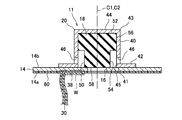
- FIG. 1 is a perspective view showing a cylindrical nickel-hydrogen secondary battery according to an embodiment of the present invention partially broken away. It is sectional drawing which expanded and showed the part of the sealing body of the nickel-hydrogen secondary battery which concerns on embodiment of this invention. It is sectional drawing which showed roughly the shape of the oxygen block layer which concerns on embodiment of this invention.
- the electrode group 22 is formed of a strip-shaped positive electrode 24, a negative electrode 26, and a separator 28, respectively. Specifically, the electrode group 22 is formed by spirally winding a positive electrode 24 and a negative electrode 26 that are stacked with a separator 28 interposed therebetween. The outermost periphery of the electrode group 22 is formed by a part of the negative electrode 26 (outermost periphery) and is in contact with the inner peripheral wall of the outer can 10. That is, the negative electrode 26 and the outer can 10 are electrically connected to each other.
- alkaline electrolyte (not shown) is injected into the outer can 10.
- This alkaline electrolyte advances the charge/discharge reaction between the positive electrode 24 and the negative electrode 26.
- this alkaline electrolyte one used in a general nickel-hydrogen secondary battery is used.
- the positive electrode additive is appropriately selected as necessary to improve the characteristics of the positive electrode.
- Examples of the main positive electrode additive include yttrium oxide and zinc oxide.
- the positive electrode 24 can be manufactured as follows, for example. First, a positive electrode mixture slurry containing a positive electrode active material powder, which is an aggregate of positive electrode active material particles, a conductive material, a positive electrode additive, water, and a binder is prepared. The obtained positive electrode mixture slurry is filled in, for example, nickel foam and dried. After drying, the foamed nickel filled with nickel hydroxide particles and the like is rolled and then cut. As a result, the positive electrode 24 holding the positive electrode mixture is manufactured.
- a positive electrode active material powder which is an aggregate of positive electrode active material particles, a conductive material, a positive electrode additive, water, and a binder is prepared.
- the obtained positive electrode mixture slurry is filled in, for example, nickel foam and dried. After drying, the foamed nickel filled with nickel hydroxide particles and the like is rolled and then cut. As a result, the positive electrode 24 holding the positive electrode mixture is manufactured.
- the negative electrode mixture contains particles of a hydrogen storage alloy, a negative electrode additive, a conductive material and a binder.
- the hydrogen storage alloy is an alloy capable of storing and releasing hydrogen, which is a negative electrode active material.
- the kind of the hydrogen storage alloy is not particularly limited, but a rare earth-Mg-Ni system hydrogen storage alloy containing a rare earth element, Mg and Ni is preferably used.
- the above-mentioned binder functions to bind the particles of the hydrogen storage alloy, the negative electrode additive and the conductive material to each other and at the same time bind the negative electrode mixture to the negative electrode core.
- a hydrophilic or hydrophobic polymer can be used as the binder, and carbon black, graphite, nickel powder or the like can be used as the conductive material.
- the negative electrode additive is appropriately selected as necessary to improve the characteristics of the negative electrode.
- the negative electrode 26 can be manufactured, for example, as follows. First, a hydrogen storage alloy powder, a conductive material, a binder, and water are prepared, and these are kneaded to prepare a negative electrode mixture paste. In addition, you may add a negative electrode additive further as needed. The obtained negative electrode mixture paste is applied to the negative electrode core body and dried. After drying, the negative electrode core to which the hydrogen storage alloy particles and the like are attached is rolled to increase the packing density of the hydrogen storage alloy, and then cut into a predetermined shape, whereby the negative electrode 26 is manufactured.
- the positive electrode 24 and the negative electrode 26 manufactured as described above are spirally wound with the separator 28 interposed, and thus the electrode group 22 is formed.
- the cover plate 14 is a disk-shaped member having conductivity, which is manufactured by processing a plate material made of nickel-plated steel, and is an inner surface 14a located inside the battery 2 and an opposite side to the inner surface 14a.
- the outer surface 14 b is located outside the battery 2.
- a central through hole 16 is provided in the center of the cover plate 14 as a ventilation hole penetrating from the inner surface 14a to the outer surface 14b.
- the central through hole 16 is normally closed by a valve body 18 described later.
- a lid plate 14 and a ring-shaped insulating packing 12 surrounding the lid plate 14 are arranged in the opening of the outer can 10, and the lid plate 14 and the insulating packing 12 are formed by caulking an opening edge 37 of the outer can 10. It is fixed to the opening edge 37 of the outer can 10.
- valve element 18 a valve element used in a general nickel-hydrogen secondary battery is used.
- a columnar or stepped columnar valve body made of a rubber material is used.
- the valve body 18 made of a rubber material is elastically deformable and is housed in the positive electrode cap 20 in a compressed state to some extent.
- the head portion 52 of the valve body 18 abuts on the inner surface of the top wall 44 of the positive electrode cap 20, and the valve body 18 is entirely pressed toward the lid plate 14.
- the base end surface 58 of the main body 54 of the valve body 18 covers the central through hole 16 and hermetically closes it. That is, the valve body 18 closes the central through hole 16 with a predetermined pressure.
- the oxygen blocking layer 60 as a coating layer for suppressing the permeation of oxygen is provided at predetermined positions on the inner surface 14a of the lid plate 14 and the surface of the positive electrode lead 30.
- the oxygen block layer 60 is formed of a material that can prevent the permeation of oxygen.
- a sealing agent used for maintaining airtightness is preferable. Further, since this sealing agent may come into contact with the alkaline electrolyte, it is more preferable that the sealing agent does not deteriorate in an alkaline atmosphere.
- a sealant include blown asphalt. This blown asphalt is used by dissolving it in an organic solvent (for example, toluene) to form a paste.
- the same effect can be obtained by using a rubber material.
- preferable rubber-based materials include rubber-based materials having alkali resistance, and specific examples thereof include ethylene propylene diene rubber.
- a material containing an additive such as chlorine or sulfur may promote the generation of rust in the metal material, so that a material containing chlorine or sulfur as an additive should be avoided.
- the material for forming the oxygen block layer 60 is not limited to the above-mentioned sealing agent, and is not particularly limited as long as it is an alkali-resistant material capable of coating the metal portion.
- the range in which the oxygen block layer 60 is formed is preferably a range that can cover a portion that is easily oxidized by oxygen gas.
- the portions of the cover plate 14 and the positive electrode lead 30 that are likely to be oxidized are the portions where the nickel plating layer is degenerated, thinned, or peeled off. Such a portion is mostly generated by the influence of welding work. That is, the welded portion W where the cover plate 14 and the positive electrode lead 30 are overlapped with each other is likely to be a portion where the nickel plating layer is denatured, thinned, or peeled off. Therefore, the oxygen block layer 60 is formed at least in the range where the positive electrode lead 30 overlaps the cover plate 14 and covers the welded portion W that is welded.
- the central through hole 16 is provided in the cover plate 14, but it is preferable to provide the oxygen blocking layer 60 also on the inner peripheral surface of the central through hole 16.
- the oxygen blocking layer 60 By providing the oxygen blocking layer 60 on the inner peripheral surface of the central through hole 16, it is possible to suppress the generation of rust with the inner peripheral surface of the central through hole 16 as a base point, which is more preferable.
- the thickness of the oxygen block layer 60 is less than 3 ⁇ m, it is not possible to sufficiently prevent the permeation of oxygen, and it is not possible to suppress the generation of rust.
- the thickness of the oxygen block layer 60 is set to 9 ⁇ m or more. This is because it is possible to more reliably prevent the permeation of oxygen and suppress the generation of rust.
- a thicker oxygen blocking layer 60 is preferable because it can block the permeation of oxygen.
- the thickness of the oxygen block layer 60 is preferably 9 ⁇ m or more and 80 ⁇ m or less, and more preferably 9 ⁇ m or more and 16 ⁇ m or less.
- Example 1 Production of nickel-hydrogen secondary battery (Example 1) (1) Manufacturing of Sealing Body First, a valve body 18 made of ethylene propylene diene rubber, which is generally used for nickel-hydrogen secondary batteries, was prepared. As shown in FIG. 2, the valve body 18 includes a cylindrical head portion 52 and a main body portion 54 having a diameter smaller than that of the head portion 52. The central axis C1 of the head portion 52 and the central axis C2 of the main body portion 54 coincide with each other. That is, the head portion 52 and the main body portion 54 are coaxial with each other. Therefore, the valve body 18 has a stepped cylindrical shape as a whole.
- the positive electrode cap 20 includes a cylindrical body portion 40, an annular flange 42 provided at the periphery of the opening 45 of the base end 41 of the body portion 40, and a base end 41.
- a gas vent hole 46 that opens to the side is formed in the lower portion of the body portion 40.
- the radius of the flange 42 was 4.9 mm.
- the inner surface 14a of the lid plate 14 of the sealing body 11 and the one end 38 of the positive electrode lead 30 were overlapped and welded.
- the positive electrode 24 and the positive electrode terminal (positive electrode cap 20) were electrically connected via the cover plate 14 and the positive electrode lead 30.
- the sealing agent is applied to a region of the inner surface 14a of the lid plate 14 excluding the surface where the lid plate 14 and the one end 38 of the positive electrode lead 30 are in contact with each other.
- the sealant was applied to a region excluding the surface where the one end portion 38 of 30 and the cover plate 14 are in contact with each other and the surface where the positive electrode lead 30 and the positive electrode 24 are in contact with each other to form the oxygen block layer 60. That is, the oxygen block layer 60 is formed over substantially the entire surface of the positive electrode lead 30 and the entire inner surface 14 a of the cover plate 14 including the range that covers the welded portion W where the cover plate 14 and the one end 38 of the positive electrode lead 30 are overlapped. Formed.
- a paste prepared by dissolving blown asphalt in toluene was used as the sealant.
- Example 2 The sealing agent is applied only to the entire surface of the positive electrode lead 30 except the surface where the one end 38 of the positive electrode lead 30 is in contact with the lid plate 14 and the surface where the positive electrode lead 30 is in contact with the positive electrode 24.
- a hydrogen secondary battery was manufactured. That is, in the second embodiment, the oxygen blocking layer 60 is formed only on the surface of the positive electrode lead 30 that is not in contact with other members. As a result of observing the unevenness of the oxygen block layer 60, no unevenness was observed.
- Example 3 The sealant is applied only to the range covering the welded portion W where the cover plate 14 and the one end 38 of the positive electrode lead 30 are overlapped to form the oxygen block layer 60, and the thickness of the oxygen block layer 60 is A nickel-hydrogen secondary battery in a usable state was manufactured in the same manner as in Example 1 except that the sealant was applied so as to have a thickness of 5 ⁇ m. As a result of observing the unevenness of the oxygen block layer 60, no unevenness was observed.
- Example 4 A usable nickel-hydrogen secondary battery was manufactured in the same manner as in Example 1 except that the sealant was applied so that the oxygen block layer 60 had a thickness of 9 ⁇ m. As a result of observing the unevenness of the oxygen block layer 60, no unevenness was observed.
- Example 5 The sealing agent is applied only to the entire surface of the positive electrode lead 30 except for the surface where the one end 38 of the positive electrode lead 30 is in contact with the lid plate 14 and the surface where the positive electrode lead 30 is in contact with the positive electrode 24.
- a hydrogen secondary battery was manufactured. That is, in Example 5, the oxygen blocking layer 60 is formed only on the surface of the positive electrode lead 30 that is not in contact with other members. As a result of observing the unevenness of the oxygen block layer 60, no unevenness was observed.
- Example 6 The sealant is applied only to the range covering the welded portion W where the cover plate 14 and the one end 38 of the positive electrode lead 30 are overlapped to form the oxygen block layer 60, and the thickness of the oxygen block layer 60 is A nickel-hydrogen secondary battery in a usable state was manufactured in the same manner as in Example 1 except that the sealing agent was applied so as to have a thickness of 9 ⁇ m. As a result of observing the unevenness of the oxygen block layer 60, no unevenness was observed.
- Example 7 A usable nickel-hydrogen secondary battery was manufactured in the same manner as in Example 1 except that the sealant was applied so that the oxygen block layer 60 had a thickness of 16 ⁇ m. As a result of observing the unevenness of the oxygen block layer 60, no unevenness was observed.
- Example 8 The sealing agent is applied only to the entire surface of the positive electrode lead 30 except the surface where the one end 38 of the positive electrode lead 30 is in contact with the lid plate 14 and the surface where the positive electrode lead 30 is in contact with the positive electrode 24.
- a hydrogen secondary battery was manufactured. That is, in Example 8, the oxygen blocking layer 60 is formed only on the surface of the entire surface of the positive electrode lead 30 that is not in contact with other members. As a result of observing the unevenness of the oxygen block layer 60, no unevenness was observed.
- Example 9 The sealant is applied only to the range covering the welded portion W where the cover plate 14 and the one end 38 of the positive electrode lead 30 are overlapped to form the oxygen block layer 60, and the thickness of the oxygen block layer 60 is A nickel-hydrogen secondary battery in a usable state was manufactured in the same manner as in Example 1 except that the sealing agent was applied to have a thickness of 16 ⁇ m. As a result of observing the unevenness of the oxygen block layer 60, no unevenness was observed.
- Example 10 A usable nickel-hydrogen secondary battery was manufactured in the same manner as in Example 1 except that the sealant was applied so that the oxygen blocking layer 60 had a thickness of 80 ⁇ m. As a result of observing the unevenness of the oxygen block layer 60, no unevenness was observed.
- Example 11 The sealing agent is applied only to the entire surface of the positive electrode lead 30 except for the surface where the one end 38 of the positive electrode lead 30 is in contact with the lid plate 14 and the surface where the positive electrode lead 30 is in contact with the positive electrode 24.
- a hydrogen secondary battery was manufactured. That is, in Example 11, the oxygen block layer 60 is formed only on the surface of the entire surface of the positive electrode lead 30 that is not in contact with other members. As a result of observing the unevenness of the oxygen block layer 60, no unevenness was observed.
- Example 12 The sealant is applied only to the range covering the welded portion W where the cover plate 14 and the one end 38 of the positive electrode lead 30 are overlapped to form the oxygen block layer 60, and the thickness of the oxygen block layer 60 is A nickel-hydrogen secondary battery in a usable state was manufactured in the same manner as in Example 1 except that the sealing agent was applied so as to have a thickness of 80 ⁇ m. As a result of observing the unevenness of the oxygen block layer 60, no unevenness was observed.
- Example 13 A nickel-hydrogen secondary battery in a usable state was manufactured in the same manner as in Example 1 except that the sealing agent was applied using a roller so that the oxygen blocking layer 60 had a thickness of 3 ⁇ m. As a result of observing the unevenness of the oxygen block layer 60, no unevenness was observed.
- Example 1 A usable nickel-hydrogen secondary battery was manufactured in the same manner as in Example 1 except that the sealing agent was not applied to the lid plate 14 and the positive electrode lead 3 and the oxygen blocking layer 60 was not formed.
- Example 2 A nickel-hydrogen secondary battery in a usable state was manufactured in the same manner as in Example 1 except that the sealant was applied so that the oxygen blocking layer 60 had a thickness of 3 ⁇ m. As a result of observing the unevenness of the oxygen block layer 60, the unevenness was recognized.
- the percentage of the surface area of the portion where rust was generated was calculated with respect to the total surface area of the inner surface 14a of the cover plate 14 and the entire surface of the positive electrode lead 30 that was not in contact with other members.
- the results are shown in Table 1 as the rust generation rate.
- the rust occurrence rate is 100%, it indicates that rust is entirely generated on the inner surface 14a of the lid plate 14 and the entire surface of the positive electrode lead 30, and the lower the rust occurrence rate is, the less rust is generated.
- the generation ratio is 0%, it means that rust is not generated.
- the oxygen blocking layer 60 was uneven, and an extremely thin portion was generated. The thickness of this thin portion is considered to be less than 3 ⁇ m. Therefore, even if the oxygen blocking layer 60 is applied to have a thickness of 3 ⁇ m, if an extremely thin portion of less than 3 ⁇ m occurs due to uneven coating of the sealant, corrosion of the metal portion due to oxygen gas can be suppressed. It can be seen that rusting occurs because it cannot be done. Therefore, it is understood that the thickness of the thinnest portion of the oxygen block layer 60 should be 3 ⁇ m or more.
- the rust generation rate was suppressed to 80% or less. It can be seen that the generation of rust can be suppressed more than that.
- a portion where the oxygen block layer 60 is formed is a first pattern which is a welded portion of the positive electrode lead and the lid plate, a second pattern which is only the positive electrode lead, and a third pattern which is the entire positive electrode lead and the inner surface of the lid plate.
- the first pattern has the highest rust generation rate
- the second pattern has a medium level
- the third pattern has the lowest rate. From this, it can be said that the portion where the oxygen block layer 60 is formed is preferably the third pattern because the third pattern can most suppress the generation of rust.
- Example 1 in which the thickness of the oxygen block layer 60 was 5 ⁇ m, the rust generation ratio was 50. %Met.
- Example 4 in which the thickness of the oxygen block layer 60 is 9 ⁇ m, Example 7 in which the thickness of the oxygen block layer 60 is 16 ⁇ m, and Example 10 in which the thickness of the oxygen block layer 60 is 80 ⁇ m are In all cases, the rust generation rate was 0%, no rust was generated, and the inner surface 14a of the cover plate 14 and the positive electrode lead 30 maintained the metallic luster, and were in an almost initial state.
- the inner surface 14a of the lid plate 14 and the positive electrode lead 30 are reliably protected by the oxygen blocking layer 60 and are not corroded by oxygen gas even if oxygen gas is generated due to continuous charging. It is conceivable that. As described above, since the inner surface 14a of the cover plate and the positive electrode lead 30 can maintain the initial state, it is apparent that the leakage due to the increase of the internal resistance value and the corrosion can be avoided. From this, it is more preferable to adopt the third pattern in which the portion where the oxygen blocking layer 60 is formed is the entire positive electrode lead and the inner surface of the lid plate, and the thickness of the oxygen blocking layer 60 is 9 ⁇ m or more. I can say.
- the oxygen blocking layer 60 is formed to have a uniform thickness of 3 ⁇ m as in Example 13, it can be said that the occurrence of rust is suppressed more than that of Comparative Example 2 having unevenness. From this, it can be said that the thickness of the thinnest portion of the oxygen block layer 60 should be 3 ⁇ m or more.
- the nickel-hydrogen secondary battery according to the present invention is less susceptible to the influence of oxygen gas and can suppress the generation of rust even in a situation where an overcharged state such as continuous charging is likely. Therefore, according to the present invention, it is possible to supply a high-quality battery capable of suppressing the problems associated with the occurrence of rust, for example, suppressing the increase of the internal resistance value and the leakage of the alkaline electrolyte. ..
- the present invention is not limited to the above-described embodiments and examples, and various modifications can be made.
- the type of battery is not limited to a nickel-hydrogen secondary battery, and nickel-cadmium It may be a secondary battery or the like.
- the shape of the battery is not limited to the cylindrical shape, and may be a rectangular shape.
- a first aspect of the present invention is an electrode group including a positive electrode and a negative electrode facing each other via a separator, and an outer can having an opening at an upper end, the electrode group containing the electrode group together with an electrolytic solution.
- a positive electrode lead that is electrically connected to an inner surface of the lid plate that is located inside the outer can, and the other end portion is electrically connected to the positive electrode; and the one end of the positive electrode lead.
- a coating layer that covers at least a range in which the cover portion and the inner surface of the lid plate overlap, and a coating layer that suppresses oxygen permeation, and the thickness of the thinnest portion of the coating layer is 3 ⁇ m or more. It is an alkaline secondary battery.
- the cover plate and the positive electrode lead are protected by the coating layer, and oxidation due to oxygen gas is suppressed. It is possible to prevent the occurrence of malfunctions.
- the coating layer covers a range of the entire surface of the positive electrode lead excluding a surface where the positive electrode lead is in contact with another member. It is an alkaline secondary battery that covers.
- the portion of the surface of the positive electrode lead that may be exposed to oxygen gas is entirely covered with the coating layer, it is possible to more reliably suppress the generation of rust. For example, even if a pinhole is generated in the nickel plating of the positive electrode lead, the generation of rust can be suppressed.
- a third aspect of the present invention is the above-described first aspect of the present invention, wherein the coating layer is a range excluding a surface of the inner surface of the lid plate where the lid plate is in contact with another member. And an alkaline secondary battery which covers the entire area of the positive electrode lead except the surface in which the positive electrode lead is in contact with another member.
- portions of the surfaces of the lid plate and the positive electrode lead that may be exposed to oxygen gas are entirely covered with the coating layer, so that the occurrence of rust can be suppressed more reliably. You can For example, even if pinholes are formed in the nickel plating on the lid plate or the positive electrode lead, the generation of rust can be suppressed.
- a fourth aspect of the present invention is the alkaline secondary battery according to any one of the first to third aspects of the present invention, in which the coating layer contains blown asphalt.
- the blown asphalt hardly permeates oxygen and also has alkali resistance, stable generation of rust on the lid plate and the positive electrode lead in the alkaline secondary battery. Can be suppressed.
- Nickel-hydrogen secondary battery 10
- Outer can 12
- Insulating packing 11
- Sealing body 14
- Lid plate 16
- Valve body 20
- Positive electrode cap positive electrode terminal
- positive electrode 26
- negative electrode 28
- separator 42
- flange 60
- oxygen block layer coating layer
Abstract
According to the present invention, a nickel hydrogen secondary battery 2 is provided with: an electrode group 22 that comprises a positive electrode 24 and a negative electrode 26, which face each other with a separator 28 being interposed therebetween; an outer package can 10 which has an opening at the top, and which contains the electrode group 22 together with an electrolyte solution; a sealing body 11 which comprises a cover plate 14 that is fitted into the opening of the outer package can 10, and a positive electrode cap 20 that is electrically connected to an outer surface 14b of the cover plate 14; a positive electrode lead 30 which has one end 38 electrically connected to an inner surface 14a of the cover plate 14, while having the other end electrically connected to the positive electrode 24; and an oxygen blocking layer 60 which covers at least a region where the one end 38 of the positive electrode lead 30 and the inner surface 14a of the cover plate 14 overlap with each other, and which suppresses permeation of oxygen. The thinnest part of the oxygen blocking layer 60 has a thickness of 3 μm or more.
Description
本発明は、アルカリ二次電池に関する。
The present invention relates to an alkaline secondary battery.
アルカリ二次電池の一種として、水素吸蔵合金を含む負極を備えたニッケル水素二次電池が知られている。このニッケル水素二次電池は、出力特性に優れていることから、各種機器の電源として使用されている。このようなニッケル水素二次電池としては、密閉型のニッケル水素二次電池が一般的である。この密閉型のニッケル水素二次電池は、一方端に開口を有し、他方端が負極端子を兼ねている外装缶と、この外装缶の中にアルカリ電解液とともに収容されている電極群と、上記した外装缶の開口を気密に閉塞する封口体とを備えている。
A nickel-hydrogen secondary battery equipped with a negative electrode containing a hydrogen storage alloy is known as a type of alkaline secondary battery. The nickel-hydrogen secondary battery is used as a power source for various devices because it has excellent output characteristics. As such a nickel-hydrogen secondary battery, a sealed nickel-hydrogen secondary battery is generally used. This sealed nickel-hydrogen secondary battery has an outer can having an opening at one end and the other end also serving as a negative electrode terminal, and an electrode group housed in this outer can together with an alkaline electrolyte, And a sealing body that hermetically closes the opening of the outer can.
上記した封口体は、外装缶の開口に嵌め合わされる蓋板であって、中央に通気孔が穿設されている蓋板と、この通気孔を塞ぐように配設されている弁体と、この弁体を収容し、蓋板に溶接されている正極キャップとを備えている。この正極キャップは、筒状の胴体部と、胴体部の一方端を閉塞する頂壁と、頂壁とは反対側の開口の周縁に設けられたフランジとを有しており、正極端子を兼ねている。なお、胴体部の側面にはガス抜き孔が設けられている。
The above-mentioned sealing body is a lid plate fitted into the opening of the outer can, and a lid plate having a vent hole in the center, and a valve body arranged so as to close the vent hole, The positive electrode cap which accommodates this valve body and is welded to the cover plate is provided. This positive electrode cap has a tubular body portion, a top wall that closes one end of the body portion, and a flange that is provided on the peripheral edge of the opening on the side opposite to the top wall, and also functions as a positive electrode terminal. ing. A gas vent hole is provided on the side surface of the body portion.
上記した弁体は、弾性材料、例えば、ゴム系材料により形成され、正極キャップの頂壁と蓋板との間に圧縮された状態で配設されており、所定の圧力まで通気孔の開口端を閉塞して電池の密閉性を保つ。この弁体は、電池内でガスが異常発生し、ガスの圧力が一定値を超えた場合、通気孔の開口端を開放してガスを放出し、電池が破裂することを防止する。つまり、この弁体は、安全弁として機能する。
The valve body described above is made of an elastic material, for example, a rubber-based material, and is arranged in a compressed state between the top wall of the positive electrode cap and the lid plate. To keep the battery airtight. When the gas abnormally occurs in the battery and the pressure of the gas exceeds a certain value, this valve body opens the opening end of the vent hole to release the gas and prevent the battery from bursting. That is, this valve body functions as a safety valve.
上記した電極群は、セパレータを介して重ね合わされた正極及び負極を含んでいる。電極群の最外部は負極により形成されている。この電極群の最外部に位置する負極が外装缶の内壁と接触することにより、負極と負極端子とは電気的に接続されている。一方、電極群の正極と蓋板との間には、例えば、金属製の帯状体で形成された正極リードが配設され、正極リードの一方端部が蓋板に溶接され、正極リードの他方端部が正極の一部に溶接されている。これにより、正極と正極端子とは、正極リード及び蓋板を介して電気的に接続されている。
The above-mentioned electrode group includes a positive electrode and a negative electrode that are stacked via a separator. The outermost part of the electrode group is formed by the negative electrode. The negative electrode located at the outermost part of the electrode group comes into contact with the inner wall of the outer can to electrically connect the negative electrode and the negative electrode terminal. On the other hand, between the positive electrode of the electrode group and the lid plate, for example, a positive electrode lead formed of a metal strip is provided, and one end of the positive electrode lead is welded to the lid plate, and the other of the positive electrode leads is welded. The end is welded to a part of the positive electrode. Thereby, the positive electrode and the positive electrode terminal are electrically connected via the positive electrode lead and the cover plate.
上記したようなニッケル水素二次電池においては、過充電が起こると正極から酸素ガスが発生するが、当該酸素ガスは、負極の水素吸蔵合金との反応によって水とすることができる。つまり、酸素ガスを負極の水素吸蔵合金で吸収できることから、電池内圧の上昇を抑えることができるので、ニッケル水素二次電池は密閉化が可能となっている。
In the nickel-hydrogen secondary battery as described above, oxygen gas is generated from the positive electrode when overcharge occurs, and the oxygen gas can be turned into water by the reaction with the hydrogen storage alloy of the negative electrode. That is, since oxygen gas can be absorbed by the hydrogen storage alloy of the negative electrode, an increase in battery internal pressure can be suppressed, so that the nickel-hydrogen secondary battery can be hermetically sealed.
ところで、ニッケル水素二次電池を使用する環境によっては、周囲温度が上昇し、正極から酸素ガスが発生しやすくなることがある。正極からの酸素ガスの発生量が、負極での酸素ガスの吸収量を上回るとニッケル水素二次電池の外装缶の破裂が起こるおそれがある。このような事態を回避するため、ニッケル水素二次電池には、上記したような安全弁が設けられている。
By the way, depending on the environment in which the nickel-hydrogen secondary battery is used, the ambient temperature may rise and oxygen gas may easily be generated from the positive electrode. If the amount of oxygen gas generated from the positive electrode exceeds the amount of oxygen gas absorbed by the negative electrode, the outer can of the nickel-hydrogen secondary battery may burst. In order to avoid such a situation, the nickel-hydrogen secondary battery is provided with the above-mentioned safety valve.
ところで、安全弁が作動すると、ガスとともにアルカリ電解液の一部も外装缶の外へ放出されてしまう。そうすると、電池の寿命が短くなるとともに、電池を収容している機器における電池周辺の部品にアルカリ電解液が付着し、斯かる部品が腐食されるおそれがある。そこで、安全弁が作動する事態となることを極力避けるべく、負極での酸素ガスの吸収を促進するための研究が種々行われている。例えば、特許文献1では、負極に白金などの貴金属触媒を添加し、酸素ガスの還元を促進する方法が開示されており、特許文献2では、水素吸蔵合金負極に撥水性層を設け、酸素ガスの負極上での吸収を促進させる技術が開示されている。
By the way, when the safety valve is activated, part of the alkaline electrolyte is discharged outside the outer can together with the gas. Then, the life of the battery is shortened, and the alkaline electrolyte may adhere to the parts around the battery in the device housing the battery, and the parts may be corroded. Therefore, various studies have been conducted to promote the absorption of oxygen gas at the negative electrode in order to avoid the situation where the safety valve is activated as much as possible. For example, Patent Document 1 discloses a method of adding a noble metal catalyst such as platinum to the negative electrode to accelerate the reduction of oxygen gas, and Patent Document 2 provides a hydrogen-absorbing alloy negative electrode with a water-repellent layer to form oxygen gas. There is disclosed a technique for accelerating the absorption on the negative electrode.
昨今、ニッケル水素二次電池は用途が益々拡大しており、例えば、緊急時の停電対策を目的としたバックアップ電源などに採用されている。
The use of nickel-hydrogen secondary batteries is expanding more and more recently, and they are used, for example, as a backup power source for the purpose of measures against power failure in an emergency.
バックアップ電源は、停電などの突発的で短い電力供給の遮断に備えて装備されているので、常時充電される連続充電方法が採用される。連続充電の場合、満充電に達してもなお充電し続けてしまうので過充電になりやすい。過充電になると上記したように正極から酸素ガスが発生するので、連続充電を採用する用途では、ほとんどの間、正極から酸素ガスが発生していることになる。
The backup power supply is equipped in case of sudden and short interruption of power supply such as power failure, so the continuous charging method that always charges is adopted. In the case of continuous charging, overcharging tends to occur because the battery will continue to be charged even when it reaches full charge. Since oxygen gas is generated from the positive electrode when overcharged as described above, oxygen gas is generated from the positive electrode most of the time in applications that employ continuous charging.
また、ニッケル水素二次電池は、充電の際、電池反応により反応熱やジュール熱が発生し温度が上昇するので、内部の水素吸蔵合金は高温にさらされる。水素吸蔵合金は、高温にさらされると劣化が進行する。連続充電の場合、高温にさらされる期間が長いので、通常の使用態様に比べ水素吸蔵合金の劣化はより進行する。
Also, when charging a nickel-hydrogen secondary battery, the reaction heat or Joule heat is generated by the battery reaction and the temperature rises, so the internal hydrogen storage alloy is exposed to high temperatures. The hydrogen storage alloy deteriorates when exposed to high temperatures. In the case of continuous charging, since the period of exposure to high temperature is long, the deterioration of the hydrogen storage alloy progresses more than in the normal usage mode.
水素吸蔵合金が劣化していない状態では、酸素ガスが発生したとしても負極にて当該酸素ガスを十分吸収可能である。しかし、水素吸蔵合金の劣化が進行してくると、水素吸蔵合金自体の酸素ガスを吸収する能力が落ちてくるので、特許文献1や特許文献2のように酸素ガスの吸収を促進する処置が施されていても、酸素ガスの吸収が進行し難くなる。このため、連続充電の期間が長くなると酸素ガスは電池内で増加してくる。そうすると、電池内の構成部材は、酸素ガスにさらされる度合いが増す。
When the hydrogen storage alloy is not deteriorated, even if oxygen gas is generated, the negative electrode can sufficiently absorb the oxygen gas. However, as the deterioration of the hydrogen storage alloy progresses, the ability of the hydrogen storage alloy itself to absorb the oxygen gas decreases, so that the measures for promoting the absorption of the oxygen gas as in Patent Documents 1 and 2 are taken. Even if it is applied, the absorption of oxygen gas becomes difficult to proceed. Therefore, oxygen gas increases in the battery as the period of continuous charging increases. Then, the constituent members in the battery are more exposed to the oxygen gas.
電池内の構成部材のうち、蓋板及び正極リードをはじめほとんどの金属系の部品は、ニッケルめっきが施された鉄系材料により形成されている。通常の充電方法によれば、酸素ガスにさらされる度合いは少ないので、これら蓋板及び正極リードは、酸化に十分耐え得る。しかし、連続充電の場合、上記のように、酸素ガスにさらされる度合いが増加するので、蓋板及び正極リードは酸化され、錆が生じてしまう。特に、蓋板と正極リードとの溶接部及びその周辺は、溶接の影響でニッケルめっき層が薄くなっている可能性があり、錆やすい。このように、蓋板と正極リードとの溶接部に錆が生じると電池の内部抵抗値が上昇し、電池が放電不能となるおそれがある。
▽ Among the components inside the battery, most of the metallic parts, including the lid plate and positive electrode lead, are made of iron-based materials plated with nickel. According to a normal charging method, the degree of exposure to oxygen gas is small, and thus the lid plate and the positive electrode lead can withstand oxidation sufficiently. However, in the case of continuous charging, since the degree of exposure to oxygen gas increases as described above, the lid plate and the positive electrode lead are oxidized and rust occurs. Particularly, the welded portion between the lid plate and the positive electrode lead and its periphery may have a thin nickel plating layer due to the influence of welding, and are easily rusted. Thus, if the welded portion between the lid plate and the positive electrode lead is rusted, the internal resistance value of the battery rises, and the battery may be unable to discharge.
また、上記のような酸化が進行すると蓋板には腐食による孔が生じ、この孔からアルカリ電解液が漏れるおそれもある。
Also, if the above-mentioned oxidation progresses, holes will be created in the cover plate due to corrosion, and the alkaline electrolyte may leak from these holes.
本発明は、上記の事情に基づいてなされたものであり、その目的とするところは、連続充電を行った場合でも電池内部の金属部品の錆の発生を抑制するとともにアルカリ電解液の漏れを抑制することができるアルカリ二次電池を提供することにある。
The present invention has been made based on the above circumstances, and an object thereof is to suppress the occurrence of rust in the metal parts inside the battery and the leakage of the alkaline electrolyte even when performing continuous charging. It is to provide an alkaline secondary battery that can be.
上記目的を達成するために、本発明によれば、セパレータを介して対向している正極及び負極を含んでいる電極群と、上端に開口を有する外装缶であって、前記電極群を電解液とともに収容している外装缶と、前記外装缶の開口に嵌め合わされている蓋板及び前記蓋板における前記外装缶の外側に位置する外面に電気的に接続されている正極端子を含む封口体と、一方端部が、前記蓋板における前記外装缶の内側に位置する内面と電気的に接続されており、他方端部が、前記正極と電気的に接続されている、正極リードと、前記正極リードの前記一方端部と前記蓋板の前記内面とが重なる範囲を少なくとも覆う被覆層であって、酸素の透過を抑制する被覆層と、を備えており、前記被覆層における最薄部の厚さが3μm以上である、アルカリ二次電池が提供される。
To achieve the above object, according to the present invention, an electrode group including a positive electrode and a negative electrode facing each other through a separator, and an outer can having an opening at the upper end, wherein the electrode group is an electrolytic solution. And an outer can that is housed together with the lid, and a lid that is fitted into the opening of the outer can, and a sealing body that includes a positive electrode terminal that is electrically connected to an outer surface of the lid located outside the outer can. A positive electrode lead having one end electrically connected to an inner surface of the lid plate located inside the outer can and the other end electrically connected to the positive electrode; and the positive electrode. A coating layer that covers at least a range in which the one end of the lead and the inner surface of the lid plate overlap with each other, and a coating layer that suppresses permeation of oxygen, and the thickness of the thinnest portion in the coating layer. An alkaline secondary battery having a size of 3 μm or more is provided.
また、前記被覆層は、前記正極リードの全面のうち前記正極リードが他の部材と接触している面を除いた範囲を覆っている構成とすることが好ましい。
Further, it is preferable that the coating layer covers the entire surface of the positive electrode lead except for the surface where the positive electrode lead is in contact with another member.
また、前記被覆層は、前記蓋板の前記内面のうち前記蓋板が他の部材と接触している面を除いた範囲、及び、前記正極リードの全面のうち前記正極リードが他の部材と接触している面を除いた範囲を覆っている構成とすることが好ましい。
In addition, the coating layer is a range of the inner surface of the lid plate excluding a surface where the lid plate is in contact with another member, and the entire positive electrode lead has the positive electrode lead as another member. It is preferable to cover the area excluding the contacting surface.
また、前記被覆層は、ブロンアスファルトを含む構成とすることが好ましい。
Also, it is preferable that the coating layer contains blown asphalt.
本発明に係るアルカリ二次電池は、セパレータを介して対向している正極及び負極を含んでいる電極群と、上端に開口を有する外装缶であって、前記電極群を電解液とともに収容している外装缶と、前記外装缶の開口に嵌め合わされている蓋板及び前記蓋板における前記外装缶の外側に位置する外面に電気的に接続されている正極端子を含む封口体と、一方端部が、前記蓋板における前記外装缶の内側に位置する内面と電気的に接続されており、他方端部が、前記正極と電気的に接続されている、正極リードと、前記正極リードの前記一方端部と前記蓋板の前記内面とが重なる範囲を少なくとも覆う被覆層であって、酸素の透過を抑制する被覆層と、を備えており、前記被覆層における最薄部の厚さが3μm以上である。これにより、連続充電により過充電状態となって酸素ガスが外装缶内に充満したとしても蓋板や正極リードといった金属部品が酸化することを抑えることができる。このため、本発明によれば、連続充電を行った場合でも電池内部の金属部品の錆の発生を抑制するとともにアルカリ電解液の漏れを抑制することができるアルカリ二次電池を提供することができる。
The alkaline secondary battery according to the present invention is an outer can having an electrode group including a positive electrode and a negative electrode facing each other through a separator, and an opening at an upper end, and the electrode group is accommodated together with an electrolytic solution. An outer can, a lid body fitted into the opening of the outer can, and a sealing body including a positive electrode terminal electrically connected to an outer surface of the lid plate located outside the outer can, and one end portion Is electrically connected to an inner surface of the lid plate located inside the outer can, and the other end is electrically connected to the positive electrode, a positive electrode lead and the one of the positive electrode leads. A coating layer that covers at least a range where the end portion and the inner surface of the lid plate overlap, and a coating layer that suppresses oxygen permeation, and the thinnest portion of the coating layer has a thickness of 3 μm or more. Is. This makes it possible to suppress oxidation of metal parts such as the lid plate and the positive electrode lead even if the exterior can is filled with oxygen gas due to continuous charging. Therefore, according to the present invention, it is possible to provide an alkaline secondary battery capable of suppressing the generation of rust on the metal components inside the battery and suppressing the leakage of the alkaline electrolyte even when continuously charged. ..
本発明が適用されるアルカリ二次電池について、例えば、円筒型ニッケル水素二次電池(以下、電池という)2に本発明を適用した場合を例に図面を参照して説明する。
An alkaline secondary battery to which the present invention is applied will be described with reference to the drawings, taking as an example the case where the present invention is applied to a cylindrical nickel-hydrogen secondary battery (hereinafter referred to as a battery) 2.
図1に示すように、電池2は、上端が開口した有底円筒形状をなす外装缶10を備えている。この外装缶10はニッケルめっき鋼製の板材を加工して形成される。外装缶10は、導電性を有しており、その底壁35は負極端子として機能する。外装缶10の中には、電極群22が収容されている。
As shown in FIG. 1, the battery 2 is equipped with a bottomed cylindrical outer can 10 having an open upper end. The outer can 10 is formed by processing a plate material made of nickel-plated steel. The outer can 10 has conductivity, and its bottom wall 35 functions as a negative electrode terminal. An electrode group 22 is housed in the outer can 10.
この電極群22は、それぞれ帯状の正極24、負極26及びセパレータ28により形成される。詳しくは、電極群22は、セパレータ28を間に挟んだ状態で重ね合わされた正極24及び負極26が渦巻状に巻回されて形成される。電極群22の最外周は負極26の一部(最外周部)により形成され、外装缶10の内周壁と接触している。即ち、負極26と外装缶10とは互いに電気的に接続されている。
The electrode group 22 is formed of a strip-shaped positive electrode 24, a negative electrode 26, and a separator 28, respectively. Specifically, the electrode group 22 is formed by spirally winding a positive electrode 24 and a negative electrode 26 that are stacked with a separator 28 interposed therebetween. The outermost periphery of the electrode group 22 is formed by a part of the negative electrode 26 (outermost periphery) and is in contact with the inner peripheral wall of the outer can 10. That is, the negative electrode 26 and the outer can 10 are electrically connected to each other.
更に、外装缶10内には、所定量のアルカリ電解液(図示せず)が注入されている。このアルカリ電解液は、正極24と負極26との間での充放電反応を進行させる。このアルカリ電解液としては、一般的なニッケル水素二次電池に用いられるものが用いられる。例えば、水酸化ナトリウム水溶液を用いることが好ましい。
Furthermore, a predetermined amount of alkaline electrolyte (not shown) is injected into the outer can 10. This alkaline electrolyte advances the charge/discharge reaction between the positive electrode 24 and the negative electrode 26. As this alkaline electrolyte, one used in a general nickel-hydrogen secondary battery is used. For example, it is preferable to use an aqueous sodium hydroxide solution.
セパレータ28の材料としては、一般的なニッケル水素二次電池に用いられるものが用いられる。例えば、ポリエチレン、ポリプロピレン等のポリオレフィン繊維製不織布を用いることが好ましい。
As a material of the separator 28, a material used in a general nickel-hydrogen secondary battery is used. For example, it is preferable to use a nonwoven fabric made of polyolefin fiber such as polyethylene or polypropylene.
正極24は、多孔質構造をなし多数の空孔を有する導電性の正極基材と、前記した空孔内及び正極基材の表面に保持された正極合剤とを含む。
The positive electrode 24 includes a conductive positive electrode base material having a porous structure and a large number of pores, and a positive electrode mixture held in the pores and on the surface of the positive electrode base material.
このような正極基材としては、例えば、発泡ニッケルを用いることができる。
正極合剤は、正極活物質粒子、導電材、正極添加剤及び結着剤を含む。この結着剤は、正極活物質粒子、導電材及び正極添加剤を結着させると同時に正極合剤を正極基材に結着させる働きをする。ここで、結着剤としては、例えば、カルボキシメチルセルロースなどを用いることができる。 As such a positive electrode base material, for example, nickel foam can be used.
The positive electrode mixture contains positive electrode active material particles, a conductive material, a positive electrode additive, and a binder. This binder functions to bind the positive electrode active material particles, the conductive material and the positive electrode additive and at the same time bind the positive electrode mixture to the positive electrode base material. Here, as the binder, for example, carboxymethyl cellulose or the like can be used.
正極活物質粒子は、水酸化ニッケル粒子又は高次水酸化ニッケル粒子である。
導電材としては、例えば、コバルト酸化物(CoO)、コバルト水酸化物(Co(OH)2)等のコバルト化合物及びコバルト(Co)から選択された1種又は2種以上を用いることができる。 The positive electrode active material particles are nickel hydroxide particles or high-order nickel hydroxide particles.
As the conductive material, for example, one or more selected from cobalt compounds such as cobalt oxide (CoO) and cobalt hydroxide (Co(OH) 2 ) and cobalt (Co) can be used.
正極添加剤は、正極の特性を改善するために、必要に応じ適宜選択されたものが添加される。主な正極添加剤としては、例えば、酸化イットリウムや酸化亜鉛が挙げられる。
The positive electrode additive is appropriately selected as necessary to improve the characteristics of the positive electrode. Examples of the main positive electrode additive include yttrium oxide and zinc oxide.
正極24は、例えば、以下のようにして製造することができる。
まず、正極活物質粒子の集合体である正極活物質粉末、導電材、正極添加剤、水及び結着剤を含む正極合剤スラリーを調製する。得られた正極合剤スラリーは、例えば発泡ニッケルに充填され、乾燥させられる。乾燥後、水酸化ニッケル粒子等が充填された発泡ニッケルは、ロール圧延されてから裁断される。これにより、正極合剤を保持した正極24が製造される。 Thepositive electrode 24 can be manufactured as follows, for example.
First, a positive electrode mixture slurry containing a positive electrode active material powder, which is an aggregate of positive electrode active material particles, a conductive material, a positive electrode additive, water, and a binder is prepared. The obtained positive electrode mixture slurry is filled in, for example, nickel foam and dried. After drying, the foamed nickel filled with nickel hydroxide particles and the like is rolled and then cut. As a result, thepositive electrode 24 holding the positive electrode mixture is manufactured.
まず、正極活物質粒子の集合体である正極活物質粉末、導電材、正極添加剤、水及び結着剤を含む正極合剤スラリーを調製する。得られた正極合剤スラリーは、例えば発泡ニッケルに充填され、乾燥させられる。乾燥後、水酸化ニッケル粒子等が充填された発泡ニッケルは、ロール圧延されてから裁断される。これにより、正極合剤を保持した正極24が製造される。 The
First, a positive electrode mixture slurry containing a positive electrode active material powder, which is an aggregate of positive electrode active material particles, a conductive material, a positive electrode additive, water, and a binder is prepared. The obtained positive electrode mixture slurry is filled in, for example, nickel foam and dried. After drying, the foamed nickel filled with nickel hydroxide particles and the like is rolled and then cut. As a result, the
次に、負極26について説明する。
負極26は、帯状をなす導電性の負極芯体を有し、この負極芯体に負極合剤が保持されている。 Next, thenegative electrode 26 will be described.
Thenegative electrode 26 has a belt-shaped conductive negative electrode core body, and the negative electrode mixture holds the negative electrode core body.
負極26は、帯状をなす導電性の負極芯体を有し、この負極芯体に負極合剤が保持されている。 Next, the
The
負極芯体は、貫通孔が分布されたシート状の金属材であり、例えば、パンチングメタルシートを用いることができる。負極合剤は、負極芯体の貫通孔内に充填されるばかりでなく、負極芯体の両面上にも層状にして保持されている。
The negative electrode core is a sheet-shaped metal material in which through holes are distributed, and for example, a punching metal sheet can be used. The negative electrode mixture is not only filled in the through holes of the negative electrode core body, but also held in layers on both surfaces of the negative electrode core body.
負極合剤は、水素吸蔵合金の粒子、負極添加剤、導電材及び結着剤を含む。ここで、水素吸蔵合金は、負極活物質である水素を吸蔵及び放出可能な合金である。水素吸蔵合金の種類としては、特に限定はされないが、希土類元素、Mg及びNiを含む希土類-Mg-Ni系水素吸蔵合金が好適なものとして用いられる。上記した結着剤は水素吸蔵合金の粒子、負極添加剤及び導電材を互いに結着させると同時に負極合剤を負極芯体に結着させる働きをする。ここで、結着剤としては親水性もしくは疎水性のポリマーを用いることができ、導電材としては、カーボンブラック、黒鉛、ニッケル粉等を用いることができる。
The negative electrode mixture contains particles of a hydrogen storage alloy, a negative electrode additive, a conductive material and a binder. Here, the hydrogen storage alloy is an alloy capable of storing and releasing hydrogen, which is a negative electrode active material. The kind of the hydrogen storage alloy is not particularly limited, but a rare earth-Mg-Ni system hydrogen storage alloy containing a rare earth element, Mg and Ni is preferably used. The above-mentioned binder functions to bind the particles of the hydrogen storage alloy, the negative electrode additive and the conductive material to each other and at the same time bind the negative electrode mixture to the negative electrode core. Here, a hydrophilic or hydrophobic polymer can be used as the binder, and carbon black, graphite, nickel powder or the like can be used as the conductive material.
負極添加剤は、負極の特性を改善するために、必要に応じ適宜選択されたものが添加される。
The negative electrode additive is appropriately selected as necessary to improve the characteristics of the negative electrode.
負極26は、例えば、以下のようにして製造することができる。
まず、水素吸蔵合金粉末と、導電材と、結着剤と、水とを準備し、これらを混練して負極合剤ペーストを調製する。なお、必要に応じて負極添加剤を更に添加しても構わない。得られた負極合剤ペーストは負極芯体に塗着され、乾燥させられる。乾燥後、水素吸蔵合金粒子等が付着した負極芯体はロール圧延を施されて水素吸蔵合金の充填密度を高められた後、所定形状に裁断され、これにより負極26が製造される。 Thenegative electrode 26 can be manufactured, for example, as follows.
First, a hydrogen storage alloy powder, a conductive material, a binder, and water are prepared, and these are kneaded to prepare a negative electrode mixture paste. In addition, you may add a negative electrode additive further as needed. The obtained negative electrode mixture paste is applied to the negative electrode core body and dried. After drying, the negative electrode core to which the hydrogen storage alloy particles and the like are attached is rolled to increase the packing density of the hydrogen storage alloy, and then cut into a predetermined shape, whereby thenegative electrode 26 is manufactured.
まず、水素吸蔵合金粉末と、導電材と、結着剤と、水とを準備し、これらを混練して負極合剤ペーストを調製する。なお、必要に応じて負極添加剤を更に添加しても構わない。得られた負極合剤ペーストは負極芯体に塗着され、乾燥させられる。乾燥後、水素吸蔵合金粒子等が付着した負極芯体はロール圧延を施されて水素吸蔵合金の充填密度を高められた後、所定形状に裁断され、これにより負極26が製造される。 The
First, a hydrogen storage alloy powder, a conductive material, a binder, and water are prepared, and these are kneaded to prepare a negative electrode mixture paste. In addition, you may add a negative electrode additive further as needed. The obtained negative electrode mixture paste is applied to the negative electrode core body and dried. After drying, the negative electrode core to which the hydrogen storage alloy particles and the like are attached is rolled to increase the packing density of the hydrogen storage alloy, and then cut into a predetermined shape, whereby the
以上のようにして製造された正極24及び負極26は、セパレータ28を介在させた状態で、渦巻き状に巻回され、これにより電極群22が形成される。
The positive electrode 24 and the negative electrode 26 manufactured as described above are spirally wound with the separator 28 interposed, and thus the electrode group 22 is formed.
上記したような電極群22及びアルカリ電解液を収容した外装缶10は、その開口に封口体11が固定されている。この封口体11は、蓋板14、弁体18及び正極キャップ20を含む。
The outer can 10 containing the electrode group 22 and the alkaline electrolyte as described above has a sealing body 11 fixed to its opening. The sealing body 11 includes a lid plate 14, a valve body 18, and a positive electrode cap 20.
蓋板14は、ニッケルめっき鋼製の板材を加工して製造された導電性を有する円板形状の部材であり、電池2の内側に位置する内面14aと、この内面14aとは反対側である電池2の外側に位置する外面14bとを有している。また、蓋板14の中央には、内面14aから外面14bにかけて貫通する通気孔としての中央貫通孔16が設けられている。この中央貫通孔16は、通常、後述する弁体18により閉塞されている。外装缶10の開口内には、蓋板14及びこの蓋板14を囲むリング形状の絶縁パッキン12が配置され、蓋板14及び絶縁パッキン12は外装缶10の開口縁37をかしめ加工することにより外装缶10の開口縁37に固定されている。
The cover plate 14 is a disk-shaped member having conductivity, which is manufactured by processing a plate material made of nickel-plated steel, and is an inner surface 14a located inside the battery 2 and an opposite side to the inner surface 14a. The outer surface 14 b is located outside the battery 2. In addition, a central through hole 16 is provided in the center of the cover plate 14 as a ventilation hole penetrating from the inner surface 14a to the outer surface 14b. The central through hole 16 is normally closed by a valve body 18 described later. A lid plate 14 and a ring-shaped insulating packing 12 surrounding the lid plate 14 are arranged in the opening of the outer can 10, and the lid plate 14 and the insulating packing 12 are formed by caulking an opening edge 37 of the outer can 10. It is fixed to the opening edge 37 of the outer can 10.
蓋板14の外面14bには、ニッケルめっき鋼製の板材を加工して製造された正極キャップ20が電気的に接続されている。この正極キャップ20は、弁体18を収容する部品であるとともに、電池2における正極端子となる部品である。
A positive electrode cap 20 manufactured by processing a plate material made of nickel-plated steel is electrically connected to the outer surface 14b of the cover plate 14. The positive electrode cap 20 is a component that houses the valve body 18 and also serves as a positive electrode terminal in the battery 2.
この正極キャップ20は、図2に示すように、円筒形状の胴体部40と、胴体部40の基端41の開口45の周縁に設けられた円環状のフランジ42と、基端41とは反対側の先端部43を閉塞するように設けられた頂壁44とを有している。また、図2から明らかなように、胴体部40の下部には側方へ開口するガス抜き孔46が穿設されている。この正極キャップ20は、弁体18を覆うように配設され、フランジ42の部分が蓋板14の外面14bに溶接されている。ここで、正極キャップ20の胴体部40の内径は、蓋板14の中央貫通孔16の直径よりも大きい。
As shown in FIG. 2, the positive electrode cap 20 has a cylindrical body portion 40, an annular flange 42 provided on the periphery of the opening 45 of the base end 41 of the body portion 40, and the base end 41. And a top wall 44 provided so as to close the front end portion 43 on the side. Further, as is clear from FIG. 2, a gas vent hole 46 that opens to the side is formed in the lower portion of the body portion 40. The positive electrode cap 20 is arranged so as to cover the valve body 18, and the flange 42 is welded to the outer surface 14 b of the cover plate 14. Here, the inner diameter of the body portion 40 of the positive electrode cap 20 is larger than the diameter of the central through hole 16 of the lid plate 14.
弁体18は、一般的なニッケル水素二次電池に用いられているものが用いられる。好ましくは、例えば、ゴム系材料で形成された円柱状又は段付きの円柱状の弁体が用いられる。
As the valve element 18, a valve element used in a general nickel-hydrogen secondary battery is used. Preferably, for example, a columnar or stepped columnar valve body made of a rubber material is used.
ゴム系材料で形成された弁体18は、弾性変形が可能であり、ある程度圧縮された状態で正極キャップ20の中に収容されている。これにより、弁体18は、頭部52が正極キャップ20の頂壁44の内面に当接し、全体的に蓋板14に向けて押圧される。そして、弁体18の本体部54の基端面58が中央貫通孔16を覆い気密に閉塞する。つまり、弁体18は、所定の圧力で中央貫通孔16を塞いでいる。
The valve body 18 made of a rubber material is elastically deformable and is housed in the positive electrode cap 20 in a compressed state to some extent. As a result, the head portion 52 of the valve body 18 abuts on the inner surface of the top wall 44 of the positive electrode cap 20, and the valve body 18 is entirely pressed toward the lid plate 14. Then, the base end surface 58 of the main body 54 of the valve body 18 covers the central through hole 16 and hermetically closes it. That is, the valve body 18 closes the central through hole 16 with a predetermined pressure.
電池2が過充電等されて、外装缶10内にガスが異常発生して電池2内のガスの圧力が上昇し、その圧力が所定の圧力を超えると、弁体18は圧縮されて変形し、中央貫通孔16が開かれる。その結果、外装缶10内から中央貫通孔16及び正極キャップ20のガス抜き孔46を介して外部にガスが放出される。ガスの放出により電池2内のガスの圧力が下がると弁体18は元の形状に戻り再度電池2を密閉する。
When the battery 2 is overcharged and gas is abnormally generated in the outer can 10, the pressure of the gas in the battery 2 rises, and when the pressure exceeds a predetermined pressure, the valve body 18 is compressed and deformed. , The central through hole 16 is opened. As a result, gas is released from the inside of the outer can 10 to the outside through the central through hole 16 and the gas vent hole 46 of the positive electrode cap 20. When the pressure of the gas in the battery 2 drops due to the release of the gas, the valve body 18 returns to its original shape, and the battery 2 is sealed again.
次に、図1から明らかなように、外装缶10内には、電極群22と蓋板14との間に正極リード30が配設されている。正極リード30は、ニッケルめっき鋼製の帯状体であり、その一方端部38が蓋板14の内面14aに溶接され、その他方端部が正極24の一部に溶接されている。このように、正極24に溶接された正極リード30が、正極端子(正極キャップ20)と接続されている蓋板14にも溶接されることにより、正極24と正極端子(正極キャップ20)とは、これら蓋板14及び正極リード30を介して互いに電気的に接続される。
Next, as is apparent from FIG. 1, the positive electrode lead 30 is disposed in the outer can 10 between the electrode group 22 and the cover plate 14. The positive electrode lead 30 is a strip of nickel-plated steel, and one end 38 thereof is welded to the inner surface 14 a of the cover plate 14, and the other end is welded to a part of the positive electrode 24. In this way, the positive electrode lead 30 welded to the positive electrode 24 is also welded to the lid plate 14 connected to the positive electrode terminal (positive electrode cap 20), so that the positive electrode 24 and the positive electrode terminal (positive electrode cap 20) are separated from each other. , Are electrically connected to each other through the lid plate 14 and the positive electrode lead 30.
なお、蓋板14と電極群22との間には円形の上部絶縁部材32が配置され、正極リード30は上部絶縁部材32に設けられたスリット39を通って延びている。また、電極群22と外装缶10の底部との間にも円形の下部絶縁部材34が配置されている。
A circular upper insulating member 32 is arranged between the cover plate 14 and the electrode group 22, and the positive electrode lead 30 extends through a slit 39 provided in the upper insulating member 32. A circular lower insulating member 34 is also arranged between the electrode group 22 and the bottom of the outer can 10.
本発明においては、蓋板14の内面14a及び正極リード30の表面の所定位置には、酸素の透過を抑制する被覆層としての酸素ブロック層60が設けられている。この酸素ブロック層60は、酸素の透過を阻止できる材料により形成される。このような材料としては、例えば、気密性を保持するために用いられるシール剤が好適なものとして挙げられる。また、このシール剤は、アルカリ電解液と接する可能性があるので、アルカリ雰囲気において劣化しないシール剤であることがより好ましい。このようなシール剤としては、例えば、ブロンアスファルトが挙げられる。このブロンアスファルトは、有機溶剤(例えば、トルエン)に溶かしてペースト状にしたものが用いられる。また、ブロンアスファルトの他に、ゴム系材料を採用しても同様な効果が得られる。好ましいゴム系材料としては、耐アルカリ性を有するゴム系材料が挙げられ、具体的には、エチレンプロピレンジエンゴムが挙げられる。なお、ゴム系材料の場合、塩素や硫黄といった添加物を含むものは、金属材料の錆の発生を促進させるおそれがあるので、塩素や硫黄を添加剤として含むものは避けるべきである。なお、酸素ブロック層60を形成する材料として、上記したようなシール剤に限定されるものではなく、金属部分をコーティングできる耐アルカリ性の材料であれば特に限定されない。
In the present invention, the oxygen blocking layer 60 as a coating layer for suppressing the permeation of oxygen is provided at predetermined positions on the inner surface 14a of the lid plate 14 and the surface of the positive electrode lead 30. The oxygen block layer 60 is formed of a material that can prevent the permeation of oxygen. As such a material, for example, a sealing agent used for maintaining airtightness is preferable. Further, since this sealing agent may come into contact with the alkaline electrolyte, it is more preferable that the sealing agent does not deteriorate in an alkaline atmosphere. Examples of such a sealant include blown asphalt. This blown asphalt is used by dissolving it in an organic solvent (for example, toluene) to form a paste. In addition to the blown asphalt, the same effect can be obtained by using a rubber material. Examples of preferable rubber-based materials include rubber-based materials having alkali resistance, and specific examples thereof include ethylene propylene diene rubber. In addition, in the case of a rubber material, a material containing an additive such as chlorine or sulfur may promote the generation of rust in the metal material, so that a material containing chlorine or sulfur as an additive should be avoided. The material for forming the oxygen block layer 60 is not limited to the above-mentioned sealing agent, and is not particularly limited as long as it is an alkali-resistant material capable of coating the metal portion.
酸素ブロック層60を形成する方法としては、例えば、上記したブロンアスファルトを有機溶剤に溶かしてペースト状にしたものを刷毛、ブレード、ローラ等で蓋板14や正極リード30といった金属部材36の所定範囲に塗布し、乾燥させることにより酸素ブロック層60を形成する方法を採用することが好ましい。
As a method of forming the oxygen blocking layer 60, for example, a predetermined range of the metal member 36 such as the lid plate 14 and the positive electrode lead 30 is prepared by dissolving the above-mentioned blown asphalt in an organic solvent into a paste and using a brush, a blade, a roller or the like. It is preferable to adopt a method of forming the oxygen blocking layer 60 by applying the composition to the substrate and drying.
酸素ブロック層60を形成する範囲は、酸素ガスにより酸化されやすい箇所をカバーできる範囲とすることが好ましい。蓋板14及び正極リード30において酸化されやすい箇所は、ニッケルめっき層が変質したり薄くなったり剥がれが生じたりしている部分である。このような部分は、溶接作業の影響により生じることがほとんどである。つまり、蓋板14及び正極リード30が重なり合った溶接部Wが、ニッケルめっき層が変質したり薄くなったり剥がれが生じたりしている部分となる可能性が高い。よって、少なくとも、正極リード30が蓋板14に重なり溶接されている溶接部Wを覆う範囲に酸素ブロック層60を形成する。
The range in which the oxygen block layer 60 is formed is preferably a range that can cover a portion that is easily oxidized by oxygen gas. The portions of the cover plate 14 and the positive electrode lead 30 that are likely to be oxidized are the portions where the nickel plating layer is degenerated, thinned, or peeled off. Such a portion is mostly generated by the influence of welding work. That is, the welded portion W where the cover plate 14 and the positive electrode lead 30 are overlapped with each other is likely to be a portion where the nickel plating layer is denatured, thinned, or peeled off. Therefore, the oxygen block layer 60 is formed at least in the range where the positive electrode lead 30 overlaps the cover plate 14 and covers the welded portion W that is welded.
好ましくは、上記した溶接部Wを含む、正極リード30の全体に酸素ブロック層60を形成する。詳しくは、正極リード30の全面のうち、正極リードが他の部材、例えば、蓋板14や正極24と接触している面を除いた範囲に被覆層としての酸素ブロック層60を形成する。
Preferably, the oxygen block layer 60 is formed on the entire positive electrode lead 30 including the above-mentioned welded portion W. Specifically, the oxygen blocking layer 60 as a coating layer is formed on the entire surface of the positive electrode lead 30 except for the surface where the positive electrode lead is in contact with another member such as the lid plate 14 or the positive electrode 24.
より好ましくは、蓋板14の内面14aの全体及び正極リード30の表面を覆う範囲に酸素ブロック層60を形成する。詳しくは、蓋板14の内面14aのうち、蓋板14が他の部材、例えば、正極リード30と接触している面を除いた範囲、及び、正極リード30の全面のうち、正極リードが他の部材、例えば、蓋板14や正極24と接触している面を除いた範囲に被覆層としての酸素ブロック層60を形成する。これにより、酸素ガスにさらされる可能性がある範囲を酸素ブロック層60で覆うことができる。
More preferably, the oxygen block layer 60 is formed in a range that covers the entire inner surface 14a of the cover plate 14 and the surface of the positive electrode lead 30. Specifically, of the inner surface 14a of the cover plate 14, the range where the cover plate 14 is not in contact with other members, for example, the positive electrode lead 30, and the entire surface of the positive electrode lead 30 are positive electrode leads. The oxygen block layer 60 as a coating layer is formed in a range excluding the surface contacting with the member such as the lid plate 14 or the positive electrode 24. As a result, the area that may be exposed to oxygen gas can be covered with the oxygen block layer 60.
蓋板14及び正極リード30のニッケルめっき層には、ピンホールが存在する場合があり、このピンホールを基点に酸化が進み、錆が生じることがある。このようなピンホールの位置は特定できないので、酸素ガスにさらされる可能性がある範囲の全体を覆うことがより好ましい態様となる。
There may be pinholes in the nickel plating layers of the cover plate 14 and the positive electrode lead 30, and oxidation may proceed from this pinhole as a base point and rust may occur. Since the position of such a pinhole cannot be specified, it is a more preferable embodiment to cover the entire range that may be exposed to oxygen gas.
ここで、蓋板14には、中央貫通孔16が設けられているが、この中央貫通孔16の内周面にも酸素ブロック層60を設けることが好ましい。中央貫通孔16の内周面に酸素ブロック層60を設けることにより、中央貫通孔16の内周面を基点とする錆の発生を抑制することができ、より好ましい。
Here, the central through hole 16 is provided in the cover plate 14, but it is preferable to provide the oxygen blocking layer 60 also on the inner peripheral surface of the central through hole 16. By providing the oxygen blocking layer 60 on the inner peripheral surface of the central through hole 16, it is possible to suppress the generation of rust with the inner peripheral surface of the central through hole 16 as a base point, which is more preferable.
また、酸素ブロック層60の厚さは、3μm未満であると、酸素の透過を十分に阻止することができず、錆の発生が抑えられない。好ましくは、酸素ブロック層60の厚さは9μm以上に設定する。これにより、酸素の透過をより確実に阻止することができ、錆の発生を抑えられるからである。酸素ブロック層60の厚さは、厚いほど酸素の透過を阻止できるので好ましいが、あまり厚くしても上記効果は飽和してくる。よって、酸素ブロック層60の厚さは、9μm以上、80μm以下とすることが好ましく、より好ましくは、9μm以上、16μm以下とする。
Also, if the thickness of the oxygen block layer 60 is less than 3 μm, it is not possible to sufficiently prevent the permeation of oxygen, and it is not possible to suppress the generation of rust. Preferably, the thickness of the oxygen block layer 60 is set to 9 μm or more. This is because it is possible to more reliably prevent the permeation of oxygen and suppress the generation of rust. A thicker oxygen blocking layer 60 is preferable because it can block the permeation of oxygen. However, even if it is too thick, the above effect is saturated. Therefore, the thickness of the oxygen block layer 60 is preferably 9 μm or more and 80 μm or less, and more preferably 9 μm or more and 16 μm or less.
ここで、酸素ブロック層60は、全体として厚さが均一であることが理想である。しかしながら、酸素ブロック層60の形成条件等により厚さが不均一になることがある。設定した厚さが小さい場合、例えば、3μm程度の場合、部分的に3μmを下回り、極端に薄い部分が形成されることがある。このような場合、斯かる極端に薄い部分を起点として錆が発生することがある。
Ideally, the oxygen block layer 60 has a uniform thickness as a whole. However, the thickness may become non-uniform depending on the formation conditions of the oxygen block layer 60 and the like. When the set thickness is small, for example, about 3 μm, the thickness may be partially less than 3 μm and an extremely thin portion may be formed. In such a case, rust may occur starting from such an extremely thin portion.
よって、図3に示すように、金属部材36の表面上に形成された酸素ブロック層60については、最も薄い最薄部62の厚さTを3μm以上に設定する。
Therefore, as shown in FIG. 3, in the oxygen block layer 60 formed on the surface of the metal member 36, the thickness T of the thinnest thinnest portion 62 is set to 3 μm or more.
酸素ブロック層60において、極端に薄い部分、例えば、厚さが3μm未満の部分が生じていると、酸素ブロック層60の外観は、色合いに濃淡が生じ、いわゆるムラがある状態となる。つまり、ムラが生じていると、厚さが3μm未満の極端に薄い部分が生じており、最薄部62の厚さTが3μm以上という条件を満たしていないことの目安になる。
If the oxygen block layer 60 has an extremely thin portion, for example, a portion having a thickness of less than 3 μm, the appearance of the oxygen block layer 60 will have a shade in the color shade, and will be in a so-called uneven state. That is, when unevenness occurs, an extremely thin portion having a thickness of less than 3 μm is generated, which is a standard that the thickness T of the thinnest portion 62 does not satisfy the condition of 3 μm or more.
以上説明したように、本発明によれば、封口体11における蓋板14及び正極リード30の表面の適切な部位に酸素ブロック層60が存在するので、電池2を連続充電した際に、過充電状態となって酸素ガスが発生したとしても蓋板14及び正極リード30が酸化され、錆が生じることは有効に防止することができる。このため、錆に起因する内部抵抗値の上昇やアルカリ電解液の漏れを抑制することができ、より高品質の電池を提供することができる。
As described above, according to the present invention, since the oxygen blocking layer 60 is present at appropriate portions on the surfaces of the lid plate 14 and the positive electrode lead 30 in the sealing body 11, when the battery 2 is continuously charged, overcharging is performed. Even if oxygen gas is generated in this state, the lid plate 14 and the positive electrode lead 30 can be effectively prevented from being oxidized and rusted. Therefore, it is possible to suppress an increase in internal resistance value and leakage of the alkaline electrolyte due to rust, and it is possible to provide a battery of higher quality.
[実施例]
1.ニッケル水素二次電池の製造
(実施例1)
(1)封口体の製造
まず、ニッケル水素二次電池に一般的に用いられている、エチレンプロピレンジエンゴム製の弁体18を準備した。この弁体18は、図2に示すように、円柱状の頭部52と、頭部52よりも縮径された本体部54とを含んでいる。頭部52の中心軸線C1と、本体部54の中心軸線C2とは一致している。つまり、頭部52と本体部54とは同軸上にある。このため、弁体18は、全体として段付きの円柱形状をなしている。 [Example]
1. Production of nickel-hydrogen secondary battery (Example 1)
(1) Manufacturing of Sealing Body First, avalve body 18 made of ethylene propylene diene rubber, which is generally used for nickel-hydrogen secondary batteries, was prepared. As shown in FIG. 2, the valve body 18 includes a cylindrical head portion 52 and a main body portion 54 having a diameter smaller than that of the head portion 52. The central axis C1 of the head portion 52 and the central axis C2 of the main body portion 54 coincide with each other. That is, the head portion 52 and the main body portion 54 are coaxial with each other. Therefore, the valve body 18 has a stepped cylindrical shape as a whole.
1.ニッケル水素二次電池の製造
(実施例1)
(1)封口体の製造
まず、ニッケル水素二次電池に一般的に用いられている、エチレンプロピレンジエンゴム製の弁体18を準備した。この弁体18は、図2に示すように、円柱状の頭部52と、頭部52よりも縮径された本体部54とを含んでいる。頭部52の中心軸線C1と、本体部54の中心軸線C2とは一致している。つまり、頭部52と本体部54とは同軸上にある。このため、弁体18は、全体として段付きの円柱形状をなしている。 [Example]
1. Production of nickel-hydrogen secondary battery (Example 1)
(1) Manufacturing of Sealing Body First, a
次に、厚さ0.2mmのニッケルめっき鋼板に対し、打ち抜き加工及びプレス加工を施し、フランジ付き円筒体形状の正極キャップ20を製造した。詳しくは、図2に示すように、正極キャップ20は、円筒形状の胴体部40と、胴体部40の基端41の開口45の周縁に設けられた円環状のフランジ42と、基端41とは反対側の先端部43を閉塞するように設けられた頂壁44とを有している。胴体部40の下部には側方へ開口するガス抜き孔46が穿設されている。そして、フランジ42の半径は4.9mmとした。
Next, a 0.2 mm thick nickel-plated steel plate was punched and pressed to manufacture a cylindrical positive electrode cap 20 with a flange. Specifically, as shown in FIG. 2, the positive electrode cap 20 includes a cylindrical body portion 40, an annular flange 42 provided at the periphery of the opening 45 of the base end 41 of the body portion 40, and a base end 41. Has a top wall 44 provided so as to close the tip portion 43 on the opposite side. A gas vent hole 46 that opens to the side is formed in the lower portion of the body portion 40. The radius of the flange 42 was 4.9 mm.
また、厚さ0.2mmのニッケルめっき鋼板に対し、打ち抜き加工を施し、中央に中央貫通孔16が設けられている円板状の蓋板14を製造した。
Further, a 0.2 mm thick nickel-plated steel plate was punched to manufacture a disc-shaped lid plate 14 having a central through hole 16 in the center.
次に、弁体18を正極キャップ20の内部に収容するとともに、この正極キャップ20を蓋板14の外面14b上に重ね、フランジ42の部分と蓋板14の外面14bとを溶接した。このとき、弁体18は蓋板14の中央貫通孔16を塞ぐ位置に配設した。このようにして封口体11を製造した。
Next, the valve body 18 was housed inside the positive electrode cap 20, the positive electrode cap 20 was placed on the outer surface 14b of the cover plate 14, and the flange 42 portion and the outer surface 14b of the cover plate 14 were welded. At this time, the valve body 18 was arranged at a position to close the central through hole 16 of the cover plate 14. In this way, the sealing body 11 was manufactured.
(2)AAサイズの円筒型ニッケル水素二次電池の組み立て
一般的なAAサイズのニッケル水素二次電池に用いられる正極24及び負極26を準備した。これら正極24及び負極26の間にポリプロピレン繊維製不織布により形成されたセパレータ28を挟み、正極24及び負極26の重合わせ体を形成した。そして、この重合わせ体を渦巻状に巻回し、電極群22を製造した。 (2) Assembly of AA size cylindrical nickel-hydrogen secondary battery Apositive electrode 24 and a negative electrode 26 used in a general AA-sized nickel hydrogen secondary battery were prepared. A separator 28 formed of a polypropylene fiber non-woven fabric was sandwiched between the positive electrode 24 and the negative electrode 26 to form a superposed body of the positive electrode 24 and the negative electrode 26. Then, this superposed body was spirally wound to manufacture the electrode group 22.
一般的なAAサイズのニッケル水素二次電池に用いられる正極24及び負極26を準備した。これら正極24及び負極26の間にポリプロピレン繊維製不織布により形成されたセパレータ28を挟み、正極24及び負極26の重合わせ体を形成した。そして、この重合わせ体を渦巻状に巻回し、電極群22を製造した。 (2) Assembly of AA size cylindrical nickel-hydrogen secondary battery A
ここで、正極24には、予めニッケルめっき鋼製の薄板により形成した正極リード30の他方端部を溶接しておいた。この正極リード30は、電極群22の一方端から突出するような位置に配設されている。
The positive electrode 24 was previously welded to the other end of the positive electrode lead 30 formed of a thin plate made of nickel-plated steel. The positive electrode lead 30 is arranged at a position protruding from one end of the electrode group 22.
得られた電極群22を、AAサイズ用の有底円筒形状の外装缶10内に水酸化ナトリウム水溶液からなるアルカリ電解液とともに収容した。
The obtained electrode group 22 was housed in an AA size bottomed cylindrical outer can 10 together with an alkaline electrolyte consisting of an aqueous sodium hydroxide solution.
次いで、封口体11における蓋板14の内面14aと正極リード30の一方端部38とを重ね合わせ、溶接した。これにより、正極24と正極端子(正極キャップ20)とが、蓋板14及び正極リード30を介して電気的に接続された。
Next, the inner surface 14a of the lid plate 14 of the sealing body 11 and the one end 38 of the positive electrode lead 30 were overlapped and welded. As a result, the positive electrode 24 and the positive electrode terminal (positive electrode cap 20) were electrically connected via the cover plate 14 and the positive electrode lead 30.
その後、蓋板14の内面14aのうち蓋板14と正極リード30の一方端部38とが接触している面を除いた範囲にシール剤を塗布するとともに、正極リードの全面のうち、正極リード30の一方端部38と蓋板14とが接触している面及び正極リード30と正極24とが接触している面を除いた範囲にシール剤を塗布し、酸素ブロック層60を形成した。つまり、蓋板14と正極リード30の一方端部38とが重ね合わされた溶接部Wを覆う範囲を含む正極リード30のほぼ全面及び蓋板14の内面14aのほぼ全体にわたり、酸素ブロック層60を形成した。ここで、シール剤としては、ブロンアスファルトをトルエンに溶かしてペースト状にしたものを用いた。
After that, the sealing agent is applied to a region of the inner surface 14a of the lid plate 14 excluding the surface where the lid plate 14 and the one end 38 of the positive electrode lead 30 are in contact with each other. The sealant was applied to a region excluding the surface where the one end portion 38 of 30 and the cover plate 14 are in contact with each other and the surface where the positive electrode lead 30 and the positive electrode 24 are in contact with each other to form the oxygen block layer 60. That is, the oxygen block layer 60 is formed over substantially the entire surface of the positive electrode lead 30 and the entire inner surface 14 a of the cover plate 14 including the range that covers the welded portion W where the cover plate 14 and the one end 38 of the positive electrode lead 30 are overlapped. Formed. Here, as the sealant, a paste prepared by dissolving blown asphalt in toluene was used.
このとき、酸素ブロック層60の厚さが5μmとなるようにシール剤を刷毛で塗布した。シール剤を塗布後、乾燥処理を施し、酸素ブロック層60を得た。その後、酸素ブロック層60の外観を観察した。その結果、ムラは認められなかった。ムラの有無に関しては、表1の塗布ムラの有無の欄に記載した。
At this time, a sealant was applied with a brush so that the oxygen block layer 60 had a thickness of 5 μm. After applying the sealant, a drying process was performed to obtain an oxygen block layer 60. Then, the appearance of the oxygen block layer 60 was observed. As a result, no unevenness was observed. The presence or absence of unevenness is described in the column of presence or absence of coating unevenness in Table 1.
その後、封口体11を、絶縁パッキン12を介して外装缶10の上端開口にかしめ固定した。このようにしてAAサイズの電池2を製造した。なお、製造した電池2の定格容量は2300mAhである。また、製造した電池2の寸法は、高さ50mm、直径14mmである。
上記した手順を繰り返し、電池2を3個製造した。 Then, the sealingbody 11 was caulked and fixed to the upper end opening of the outer can 10 through the insulating packing 12. Thus, the AA size battery 2 was manufactured. The manufactured battery 2 has a rated capacity of 2300 mAh. The dimensions of the manufactured battery 2 are 50 mm in height and 14 mm in diameter.
The above procedure was repeated to manufacture threebatteries 2.
上記した手順を繰り返し、電池2を3個製造した。 Then, the sealing
The above procedure was repeated to manufacture three
(3)初期活性化処理
得られた電池2に対し、温度25℃の環境下にて、0.1Cの電流で16時間の充電を行った後に、0.2Cの電流で電池電圧が0.5Vになるまで放電させる充放電作業を2回繰り返し、初期活性化処理を行った。このようにして、電池2を使用可能状態とした。 (3) Initial activation treatment The obtainedbattery 2 was charged with a current of 0.1 C for 16 hours in an environment of a temperature of 25° C., and then a battery voltage of 0. The charging/discharging work of discharging until it reached 5 V was repeated twice to perform the initial activation treatment. In this way, the battery 2 was made ready for use.
得られた電池2に対し、温度25℃の環境下にて、0.1Cの電流で16時間の充電を行った後に、0.2Cの電流で電池電圧が0.5Vになるまで放電させる充放電作業を2回繰り返し、初期活性化処理を行った。このようにして、電池2を使用可能状態とした。 (3) Initial activation treatment The obtained
(実施例2)
正極リード30の全面のうち、正極リード30の一方端部38と蓋板14とが接触している面及び正極リード30と正極24とが接触している面を除いた範囲にのみシール剤を塗布し、酸素ブロック層60を形成したこと、及び、酸素ブロック層60の厚さが5μmとなるようにシール剤を塗布したことを除いて、実施例1と同様にして、使用可能状態のニッケル水素二次電池を製造した。つまり、実施例2では、正極リード30の全面のうち他の部材と接触していない面にのみ酸素ブロック層60が形成されている。
なお、酸素ブロック層60のムラを観察した結果、ムラは認められなかった。 (Example 2)
The sealing agent is applied only to the entire surface of thepositive electrode lead 30 except the surface where the one end 38 of the positive electrode lead 30 is in contact with the lid plate 14 and the surface where the positive electrode lead 30 is in contact with the positive electrode 24. Nickel in a usable state in the same manner as in Example 1 except that the oxygen blocking layer 60 was applied to form the oxygen blocking layer 60, and the sealing agent was applied so that the oxygen blocking layer 60 had a thickness of 5 μm. A hydrogen secondary battery was manufactured. That is, in the second embodiment, the oxygen blocking layer 60 is formed only on the surface of the positive electrode lead 30 that is not in contact with other members.
As a result of observing the unevenness of theoxygen block layer 60, no unevenness was observed.
正極リード30の全面のうち、正極リード30の一方端部38と蓋板14とが接触している面及び正極リード30と正極24とが接触している面を除いた範囲にのみシール剤を塗布し、酸素ブロック層60を形成したこと、及び、酸素ブロック層60の厚さが5μmとなるようにシール剤を塗布したことを除いて、実施例1と同様にして、使用可能状態のニッケル水素二次電池を製造した。つまり、実施例2では、正極リード30の全面のうち他の部材と接触していない面にのみ酸素ブロック層60が形成されている。
なお、酸素ブロック層60のムラを観察した結果、ムラは認められなかった。 (Example 2)
The sealing agent is applied only to the entire surface of the
As a result of observing the unevenness of the
(実施例3)
蓋板14と正極リード30の一方端部38とが重ね合わされた溶接部Wを覆う範囲にのみシール剤を塗布し、酸素ブロック層60を形成したこと、及び、酸素ブロック層60の厚さが5μmとなるようにシール剤を塗布したことを除いて、実施例1と同様にして、使用可能状態のニッケル水素二次電池を製造した。
なお、酸素ブロック層60のムラを観察した結果、ムラは認められなかった。 (Example 3)
The sealant is applied only to the range covering the welded portion W where thecover plate 14 and the one end 38 of the positive electrode lead 30 are overlapped to form the oxygen block layer 60, and the thickness of the oxygen block layer 60 is A nickel-hydrogen secondary battery in a usable state was manufactured in the same manner as in Example 1 except that the sealant was applied so as to have a thickness of 5 μm.
As a result of observing the unevenness of theoxygen block layer 60, no unevenness was observed.
蓋板14と正極リード30の一方端部38とが重ね合わされた溶接部Wを覆う範囲にのみシール剤を塗布し、酸素ブロック層60を形成したこと、及び、酸素ブロック層60の厚さが5μmとなるようにシール剤を塗布したことを除いて、実施例1と同様にして、使用可能状態のニッケル水素二次電池を製造した。
なお、酸素ブロック層60のムラを観察した結果、ムラは認められなかった。 (Example 3)
The sealant is applied only to the range covering the welded portion W where the
As a result of observing the unevenness of the
(実施例4)
酸素ブロック層60の厚さが9μmとなるようにシール剤を塗布したことを除いて、実施例1と同様にして、使用可能状態のニッケル水素二次電池を製造した。なお、酸素ブロック層60のムラを観察した結果、ムラは認められなかった。 (Example 4)
A usable nickel-hydrogen secondary battery was manufactured in the same manner as in Example 1 except that the sealant was applied so that theoxygen block layer 60 had a thickness of 9 μm. As a result of observing the unevenness of the oxygen block layer 60, no unevenness was observed.
酸素ブロック層60の厚さが9μmとなるようにシール剤を塗布したことを除いて、実施例1と同様にして、使用可能状態のニッケル水素二次電池を製造した。なお、酸素ブロック層60のムラを観察した結果、ムラは認められなかった。 (Example 4)
A usable nickel-hydrogen secondary battery was manufactured in the same manner as in Example 1 except that the sealant was applied so that the
(実施例5)
正極リード30の全面のうち、正極リード30の一方端部38と蓋板14とが接触している面及び正極リード30と正極24とが接触している面を除いた範囲にのみシール剤を塗布し、酸素ブロック層60を形成したこと、及び、酸素ブロック層60の厚さが9μmとなるようにシール剤を塗布したことを除いて、実施例1と同様にして、使用可能状態のニッケル水素二次電池を製造した。つまり、実施例5では、正極リード30の全面のうち他の部材と接触していない面にのみ酸素ブロック層60が形成されている。
なお、酸素ブロック層60のムラを観察した結果、ムラは認められなかった。 (Example 5)
The sealing agent is applied only to the entire surface of thepositive electrode lead 30 except for the surface where the one end 38 of the positive electrode lead 30 is in contact with the lid plate 14 and the surface where the positive electrode lead 30 is in contact with the positive electrode 24. Nickel in a usable state in the same manner as in Example 1 except that the oxygen blocking layer 60 was applied and the sealing agent was applied so that the oxygen blocking layer 60 had a thickness of 9 μm. A hydrogen secondary battery was manufactured. That is, in Example 5, the oxygen blocking layer 60 is formed only on the surface of the positive electrode lead 30 that is not in contact with other members.
As a result of observing the unevenness of theoxygen block layer 60, no unevenness was observed.
正極リード30の全面のうち、正極リード30の一方端部38と蓋板14とが接触している面及び正極リード30と正極24とが接触している面を除いた範囲にのみシール剤を塗布し、酸素ブロック層60を形成したこと、及び、酸素ブロック層60の厚さが9μmとなるようにシール剤を塗布したことを除いて、実施例1と同様にして、使用可能状態のニッケル水素二次電池を製造した。つまり、実施例5では、正極リード30の全面のうち他の部材と接触していない面にのみ酸素ブロック層60が形成されている。
なお、酸素ブロック層60のムラを観察した結果、ムラは認められなかった。 (Example 5)
The sealing agent is applied only to the entire surface of the
As a result of observing the unevenness of the
(実施例6)
蓋板14と正極リード30の一方端部38とが重ね合わされた溶接部Wを覆う範囲にのみシール剤を塗布し、酸素ブロック層60を形成したこと、及び、酸素ブロック層60の厚さが9μmとなるようにシール剤を塗布したことを除いて、実施例1と同様にして、使用可能状態のニッケル水素二次電池を製造した。
なお、酸素ブロック層60のムラを観察した結果、ムラは認められなかった。 (Example 6)
The sealant is applied only to the range covering the welded portion W where thecover plate 14 and the one end 38 of the positive electrode lead 30 are overlapped to form the oxygen block layer 60, and the thickness of the oxygen block layer 60 is A nickel-hydrogen secondary battery in a usable state was manufactured in the same manner as in Example 1 except that the sealing agent was applied so as to have a thickness of 9 μm.
As a result of observing the unevenness of theoxygen block layer 60, no unevenness was observed.
蓋板14と正極リード30の一方端部38とが重ね合わされた溶接部Wを覆う範囲にのみシール剤を塗布し、酸素ブロック層60を形成したこと、及び、酸素ブロック層60の厚さが9μmとなるようにシール剤を塗布したことを除いて、実施例1と同様にして、使用可能状態のニッケル水素二次電池を製造した。
なお、酸素ブロック層60のムラを観察した結果、ムラは認められなかった。 (Example 6)
The sealant is applied only to the range covering the welded portion W where the
As a result of observing the unevenness of the
(実施例7)
酸素ブロック層60の厚さが16μmとなるようにシール剤を塗布したことを除いて、実施例1と同様にして、使用可能状態のニッケル水素二次電池を製造した。なお、酸素ブロック層60のムラを観察した結果、ムラは認められなかった。 (Example 7)
A usable nickel-hydrogen secondary battery was manufactured in the same manner as in Example 1 except that the sealant was applied so that theoxygen block layer 60 had a thickness of 16 μm. As a result of observing the unevenness of the oxygen block layer 60, no unevenness was observed.
酸素ブロック層60の厚さが16μmとなるようにシール剤を塗布したことを除いて、実施例1と同様にして、使用可能状態のニッケル水素二次電池を製造した。なお、酸素ブロック層60のムラを観察した結果、ムラは認められなかった。 (Example 7)
A usable nickel-hydrogen secondary battery was manufactured in the same manner as in Example 1 except that the sealant was applied so that the
(実施例8)
正極リード30の全面のうち、正極リード30の一方端部38と蓋板14とが接触している面及び正極リード30と正極24とが接触している面を除いた範囲にのみシール剤を塗布し、酸素ブロック層60を形成したこと、及び、酸素ブロック層60の厚さが16μmとなるようにシール剤を塗布したことを除いて、実施例1と同様にして、使用可能状態のニッケル水素二次電池を製造した。つまり、実施例8では、正極リード30の全面のうち他の部材と接触していない面にのみ酸素ブロック層60が形成されている。
なお、酸素ブロック層60のムラを観察した結果、ムラは認められなかった。 (Example 8)
The sealing agent is applied only to the entire surface of thepositive electrode lead 30 except the surface where the one end 38 of the positive electrode lead 30 is in contact with the lid plate 14 and the surface where the positive electrode lead 30 is in contact with the positive electrode 24. Nickel in a usable state in the same manner as in Example 1 except that the oxygen blocking layer 60 was applied and the sealing agent was applied so that the oxygen blocking layer 60 had a thickness of 16 μm. A hydrogen secondary battery was manufactured. That is, in Example 8, the oxygen blocking layer 60 is formed only on the surface of the entire surface of the positive electrode lead 30 that is not in contact with other members.
As a result of observing the unevenness of theoxygen block layer 60, no unevenness was observed.
正極リード30の全面のうち、正極リード30の一方端部38と蓋板14とが接触している面及び正極リード30と正極24とが接触している面を除いた範囲にのみシール剤を塗布し、酸素ブロック層60を形成したこと、及び、酸素ブロック層60の厚さが16μmとなるようにシール剤を塗布したことを除いて、実施例1と同様にして、使用可能状態のニッケル水素二次電池を製造した。つまり、実施例8では、正極リード30の全面のうち他の部材と接触していない面にのみ酸素ブロック層60が形成されている。
なお、酸素ブロック層60のムラを観察した結果、ムラは認められなかった。 (Example 8)
The sealing agent is applied only to the entire surface of the
As a result of observing the unevenness of the
(実施例9)
蓋板14と正極リード30の一方端部38とが重ね合わされた溶接部Wを覆う範囲にのみシール剤を塗布し、酸素ブロック層60を形成したこと、及び、酸素ブロック層60の厚さが16μmとなるようにシール剤を塗布したことを除いて、実施例1と同様にして、使用可能状態のニッケル水素二次電池を製造した。
なお、酸素ブロック層60のムラを観察した結果、ムラは認められなかった。 (Example 9)
The sealant is applied only to the range covering the welded portion W where thecover plate 14 and the one end 38 of the positive electrode lead 30 are overlapped to form the oxygen block layer 60, and the thickness of the oxygen block layer 60 is A nickel-hydrogen secondary battery in a usable state was manufactured in the same manner as in Example 1 except that the sealing agent was applied to have a thickness of 16 μm.
As a result of observing the unevenness of theoxygen block layer 60, no unevenness was observed.
蓋板14と正極リード30の一方端部38とが重ね合わされた溶接部Wを覆う範囲にのみシール剤を塗布し、酸素ブロック層60を形成したこと、及び、酸素ブロック層60の厚さが16μmとなるようにシール剤を塗布したことを除いて、実施例1と同様にして、使用可能状態のニッケル水素二次電池を製造した。
なお、酸素ブロック層60のムラを観察した結果、ムラは認められなかった。 (Example 9)
The sealant is applied only to the range covering the welded portion W where the
As a result of observing the unevenness of the
(実施例10)
酸素ブロック層60の厚さが80μmとなるようにシール剤を塗布したことを除いて、実施例1と同様にして、使用可能状態のニッケル水素二次電池を製造した。なお、酸素ブロック層60のムラを観察した結果、ムラは認められなかった。 (Example 10)
A usable nickel-hydrogen secondary battery was manufactured in the same manner as in Example 1 except that the sealant was applied so that theoxygen blocking layer 60 had a thickness of 80 μm. As a result of observing the unevenness of the oxygen block layer 60, no unevenness was observed.
酸素ブロック層60の厚さが80μmとなるようにシール剤を塗布したことを除いて、実施例1と同様にして、使用可能状態のニッケル水素二次電池を製造した。なお、酸素ブロック層60のムラを観察した結果、ムラは認められなかった。 (Example 10)
A usable nickel-hydrogen secondary battery was manufactured in the same manner as in Example 1 except that the sealant was applied so that the
(実施例11)
正極リード30の全面のうち、正極リード30の一方端部38と蓋板14とが接触している面及び正極リード30と正極24とが接触している面を除いた範囲にのみシール剤を塗布し、酸素ブロック層60を形成したこと、及び、酸素ブロック層60の厚さが80μmとなるようにシール剤を塗布したことを除いて、実施例1と同様にして、使用可能状態のニッケル水素二次電池を製造した。つまり、実施例11では、正極リード30の全面のうち他の部材と接触していない面にのみ酸素ブロック層60が形成されている。
なお、酸素ブロック層60のムラを観察した結果、ムラは認められなかった。 (Example 11)
The sealing agent is applied only to the entire surface of thepositive electrode lead 30 except for the surface where the one end 38 of the positive electrode lead 30 is in contact with the lid plate 14 and the surface where the positive electrode lead 30 is in contact with the positive electrode 24. Nickel in a usable state in the same manner as in Example 1 except that the oxygen blocking layer 60 was applied and a sealing agent was applied so that the oxygen blocking layer 60 had a thickness of 80 μm. A hydrogen secondary battery was manufactured. That is, in Example 11, the oxygen block layer 60 is formed only on the surface of the entire surface of the positive electrode lead 30 that is not in contact with other members.
As a result of observing the unevenness of theoxygen block layer 60, no unevenness was observed.
正極リード30の全面のうち、正極リード30の一方端部38と蓋板14とが接触している面及び正極リード30と正極24とが接触している面を除いた範囲にのみシール剤を塗布し、酸素ブロック層60を形成したこと、及び、酸素ブロック層60の厚さが80μmとなるようにシール剤を塗布したことを除いて、実施例1と同様にして、使用可能状態のニッケル水素二次電池を製造した。つまり、実施例11では、正極リード30の全面のうち他の部材と接触していない面にのみ酸素ブロック層60が形成されている。
なお、酸素ブロック層60のムラを観察した結果、ムラは認められなかった。 (Example 11)
The sealing agent is applied only to the entire surface of the
As a result of observing the unevenness of the
(実施例12)
蓋板14と正極リード30の一方端部38とが重ね合わされた溶接部Wを覆う範囲にのみシール剤を塗布し、酸素ブロック層60を形成したこと、及び、酸素ブロック層60の厚さが80μmとなるようにシール剤を塗布したことを除いて、実施例1と同様にして、使用可能状態のニッケル水素二次電池を製造した。
なお、酸素ブロック層60のムラを観察した結果、ムラは認められなかった。 (Example 12)
The sealant is applied only to the range covering the welded portion W where thecover plate 14 and the one end 38 of the positive electrode lead 30 are overlapped to form the oxygen block layer 60, and the thickness of the oxygen block layer 60 is A nickel-hydrogen secondary battery in a usable state was manufactured in the same manner as in Example 1 except that the sealing agent was applied so as to have a thickness of 80 μm.
As a result of observing the unevenness of theoxygen block layer 60, no unevenness was observed.
蓋板14と正極リード30の一方端部38とが重ね合わされた溶接部Wを覆う範囲にのみシール剤を塗布し、酸素ブロック層60を形成したこと、及び、酸素ブロック層60の厚さが80μmとなるようにシール剤を塗布したことを除いて、実施例1と同様にして、使用可能状態のニッケル水素二次電池を製造した。
なお、酸素ブロック層60のムラを観察した結果、ムラは認められなかった。 (Example 12)
The sealant is applied only to the range covering the welded portion W where the
As a result of observing the unevenness of the
(実施例13)
酸素ブロック層60の厚さが3μmとなるようにシール剤を、ローラを用いて塗布したことを除いて、実施例1と同様にして、使用可能状態のニッケル水素二次電池を製造した。なお、酸素ブロック層60のムラを観察した結果、ムラは認められなかった。 (Example 13)
A nickel-hydrogen secondary battery in a usable state was manufactured in the same manner as in Example 1 except that the sealing agent was applied using a roller so that theoxygen blocking layer 60 had a thickness of 3 μm. As a result of observing the unevenness of the oxygen block layer 60, no unevenness was observed.
酸素ブロック層60の厚さが3μmとなるようにシール剤を、ローラを用いて塗布したことを除いて、実施例1と同様にして、使用可能状態のニッケル水素二次電池を製造した。なお、酸素ブロック層60のムラを観察した結果、ムラは認められなかった。 (Example 13)
A nickel-hydrogen secondary battery in a usable state was manufactured in the same manner as in Example 1 except that the sealing agent was applied using a roller so that the
(比較例1)
蓋板14及び正極リード3にシール剤を塗布せず、酸素ブロック層60を形成しなかったことを除いて、実施例1と同様にして、使用可能状態のニッケル水素二次電池を製造した。 (Comparative Example 1)
A usable nickel-hydrogen secondary battery was manufactured in the same manner as in Example 1 except that the sealing agent was not applied to thelid plate 14 and the positive electrode lead 3 and the oxygen blocking layer 60 was not formed.
蓋板14及び正極リード3にシール剤を塗布せず、酸素ブロック層60を形成しなかったことを除いて、実施例1と同様にして、使用可能状態のニッケル水素二次電池を製造した。 (Comparative Example 1)
A usable nickel-hydrogen secondary battery was manufactured in the same manner as in Example 1 except that the sealing agent was not applied to the
(比較例2)
酸素ブロック層60の厚さが3μmとなるようにシール剤を塗布したことを除いて、実施例1と同様にして、使用可能状態のニッケル水素二次電池を製造した。なお、酸素ブロック層60のムラを観察した結果、ムラが認められた。 (Comparative example 2)
A nickel-hydrogen secondary battery in a usable state was manufactured in the same manner as in Example 1 except that the sealant was applied so that theoxygen blocking layer 60 had a thickness of 3 μm. As a result of observing the unevenness of the oxygen block layer 60, the unevenness was recognized.
酸素ブロック層60の厚さが3μmとなるようにシール剤を塗布したことを除いて、実施例1と同様にして、使用可能状態のニッケル水素二次電池を製造した。なお、酸素ブロック層60のムラを観察した結果、ムラが認められた。 (Comparative example 2)
A nickel-hydrogen secondary battery in a usable state was manufactured in the same manner as in Example 1 except that the sealant was applied so that the
2.ニッケル水素二次電池の評価
(1)連続充電試験
実施例1~13及び比較例1、2の電池について、70℃の環境下にて、0.1Cの充電電流を流し、連続充電を行った。連続充電継続中において、1ヶ月毎に電池の放電容量を測定した。そして、測定した放電容量が初期の放電容量の60%を下回った時点で電池の寿命に達したものとし、そこで連続充電を終了させた。その後、電池を25℃の室温まで冷却した。 2. Evaluation of Nickel-Hydrogen Secondary Battery (1) Continuous Charge Test The batteries of Examples 1 to 13 and Comparative Examples 1 and 2 were continuously charged under a 70° C. environment by applying a charging current of 0.1 C. .. During continuous charging, the discharge capacity of the battery was measured every month. Then, when the measured discharge capacity fell below 60% of the initial discharge capacity, it was determined that the battery had reached the end of its life, and then continuous charging was terminated. Then, the battery was cooled to room temperature of 25°C.
(2)電池の破壊検査
次に、連続充電試験が終了した電池を解体し、内部から蓋板14と正極リード30の接合体を取り出した。そして、かかる接合体について錆の発生状態を目視観察した。錆の有無を確認し、製造した3個の電池のうち錆が発生していた電池の個数を数え、1個でも錆が発生した電池が存在した場合は「有」とし、錆が発生した電池が存在していなかった場合は「無」として、その結果を表1に示した。なお、酸素ブロック層60を有する実施例1~13及び比較例2については、酸素ブロック層60を剥がした後の状態を観察した。 (2) Battery Destruction Test Next, the battery after the continuous charging test was disassembled, and the joined body of thelid plate 14 and the positive electrode lead 30 was taken out from the inside. Then, the generation state of rust was visually observed for such a joined body. Confirm the presence of rust, count the number of rusted batteries out of the three manufactured batteries, and if there is even one rusted battery, mark “Yes” and indicate the rusted battery. When there was not, the result was shown in Table 1 as "absent". Regarding Examples 1 to 13 and Comparative Example 2 having the oxygen blocking layer 60, the state after the oxygen blocking layer 60 was peeled off was observed.
次に、連続充電試験が終了した電池を解体し、内部から蓋板14と正極リード30の接合体を取り出した。そして、かかる接合体について錆の発生状態を目視観察した。錆の有無を確認し、製造した3個の電池のうち錆が発生していた電池の個数を数え、1個でも錆が発生した電池が存在した場合は「有」とし、錆が発生した電池が存在していなかった場合は「無」として、その結果を表1に示した。なお、酸素ブロック層60を有する実施例1~13及び比較例2については、酸素ブロック層60を剥がした後の状態を観察した。 (2) Battery Destruction Test Next, the battery after the continuous charging test was disassembled, and the joined body of the
更に、蓋板14の内面14a及び正極リード30の全面のうち他の部材と接触していない面の合計の表面積に対する、錆が発生している部分の表面積の百分率を求めた。その結果を錆発生比率として表1に示した。錆発生比率が100%の場合、蓋板14の内面14a及び正極リード30の全面に全体的に錆が発生していることを示し、錆発生比率の値が低いほど錆の発生が少なく、錆発生比率が0%の場合、錆が発生していないことを示す。
Further, the percentage of the surface area of the portion where rust was generated was calculated with respect to the total surface area of theinner surface 14a of the cover plate 14 and the entire surface of the positive electrode lead 30 that was not in contact with other members. The results are shown in Table 1 as the rust generation rate. When the rust occurrence rate is 100%, it indicates that rust is entirely generated on the inner surface 14a of the lid plate 14 and the entire surface of the positive electrode lead 30, and the lower the rust occurrence rate is, the less rust is generated. When the generation ratio is 0%, it means that rust is not generated.
Further, the percentage of the surface area of the portion where rust was generated was calculated with respect to the total surface area of the

3.考察
表1より、シール剤を塗布せず、酸素ブロック層を形成していない比較例1の電池では、錆が生じており、その錆は蓋板14の内面14a及び正極リード30の全体にわたっている。これは、連続充電により過充電状態となり、酸素ガスが発生し、その酸素ガスにより金属部分が腐食され錆が発生したものと考えられる。 3. Consideration From Table 1, in the battery of Comparative Example 1 in which the sealant was not applied and the oxygen block layer was not formed, rust occurred, and the rust spreads over the entireinner surface 14a of the lid plate 14 and the positive electrode lead 30. .. It is considered that this is because the continuous charge causes an overcharged state, oxygen gas is generated, and the oxygen gas corrodes the metal part to generate rust.
表1より、シール剤を塗布せず、酸素ブロック層を形成していない比較例1の電池では、錆が生じており、その錆は蓋板14の内面14a及び正極リード30の全体にわたっている。これは、連続充電により過充電状態となり、酸素ガスが発生し、その酸素ガスにより金属部分が腐食され錆が発生したものと考えられる。 3. Consideration From Table 1, in the battery of Comparative Example 1 in which the sealant was not applied and the oxygen block layer was not formed, rust occurred, and the rust spreads over the entire
また、シール剤を塗布し、厚さ3μmの酸素ブロック層60を形成した比較例2の電池においても、錆が生じており、その錆は蓋板14の内面14a及び正極リード30の全体にわたっている。この比較例2においては、酸素ブロック層60にムラが生じており、極端に薄い部分が生じていた。この薄い部分の厚さは3μm未満であると考えられる。このことから、酸素ブロック層60の厚さが3μmとなるように塗布しても、シール剤の塗布ムラにより3μm未満の極端に薄い部分が生じると、酸素ガスによる金属部分の腐食を抑えることができず、錆が発生してしまうことがわかる。このため、酸素ブロック層60の最薄部の厚さは3μm以上とすべきであることがわかる。
Also, in the battery of Comparative Example 2 in which the sealing agent was applied to form the oxygen blocking layer 60 having a thickness of 3 μm, rust was generated, and the rust spreads over the inner surface 14a of the cover plate 14 and the positive electrode lead 30. .. In Comparative Example 2, the oxygen blocking layer 60 was uneven, and an extremely thin portion was generated. The thickness of this thin portion is considered to be less than 3 μm. Therefore, even if the oxygen blocking layer 60 is applied to have a thickness of 3 μm, if an extremely thin portion of less than 3 μm occurs due to uneven coating of the sealant, corrosion of the metal portion due to oxygen gas can be suppressed. It can be seen that rusting occurs because it cannot be done. Therefore, it is understood that the thickness of the thinnest portion of the oxygen block layer 60 should be 3 μm or more.
一方、シール剤を塗布し、厚さ5μm~80μmの酸素ブロック層60を形成した実施例1~12の電池においては、錆の発生比率が80%以下に抑えられており、比較例1及び2よりも錆の発生を抑制できていることがわかる。
On the other hand, in the batteries of Examples 1 to 12 in which the sealant was applied to form the oxygen blocking layer 60 having a thickness of 5 μm to 80 μm, the rust generation rate was suppressed to 80% or less. It can be seen that the generation of rust can be suppressed more than that.
また、酸素ブロック層60を形成する部位が、正極リードと蓋板との溶接部である第1パターン、正極リードのみである第2パターン及び正極リードの全体及び蓋板の内面である第3パターンを比較した場合、錆発生比率は、第1パターンが最も高く、第2パターンが中程度であり、第3パターンが最も低い。このことから、第3パターンが錆の発生を最も抑制できるので、酸素ブロック層60を形成する部位は、第3パターンとすることが好ましいといえる。
Further, a portion where the oxygen block layer 60 is formed is a first pattern which is a welded portion of the positive electrode lead and the lid plate, a second pattern which is only the positive electrode lead, and a third pattern which is the entire positive electrode lead and the inner surface of the lid plate. In comparison, the first pattern has the highest rust generation rate, the second pattern has a medium level, and the third pattern has the lowest rate. From this, it can be said that the portion where the oxygen block layer 60 is formed is preferably the third pattern because the third pattern can most suppress the generation of rust.
ここで、酸素ブロック層60を形成する部位が、正極リードの全体及び蓋板の内面である第3パターンにおいて、酸素ブロック層60の厚さを5μmとした実施例1では、錆発生比率が50%であった。これに対し、酸素ブロック層60の厚さを9μmとした実施例4、酸素ブロック層60の厚さを16μmとした実施例7及び酸素ブロック層60の厚さを80μmとした実施例10は、いずれも錆発生比率が0%であり、錆の発生は無く、蓋板14の内面14a及び正極リード30は金属光沢を維持しており、ほぼ初期の状態であった。これは、連続充電により過充電状態となり、酸素ガスが発生したとしても、蓋板14の内面14a及び正極リード30は、酸素ブロック層60により確実に保護され、酸素ガスによる腐食を受けなかったものと考えられる。このように、蓋板の内面14a及び正極リード30は、初期の状態を維持できているので、内部抵抗値の上昇や腐食にともなう漏液は回避できていることは明らかである。このことから、酸素ブロック層60を形成する部位が正極リードの全体及び蓋板の内面である第3パターンを採用し、且つ、酸素ブロック層60の厚さを9μm以上とすることがより好ましいといえる。
Here, in the third pattern in which the oxygen block layer 60 is formed on the entire positive electrode lead and the inner surface of the cover plate, in Example 1 in which the thickness of the oxygen block layer 60 was 5 μm, the rust generation ratio was 50. %Met. On the other hand, Example 4 in which the thickness of the oxygen block layer 60 is 9 μm, Example 7 in which the thickness of the oxygen block layer 60 is 16 μm, and Example 10 in which the thickness of the oxygen block layer 60 is 80 μm are In all cases, the rust generation rate was 0%, no rust was generated, and the inner surface 14a of the cover plate 14 and the positive electrode lead 30 maintained the metallic luster, and were in an almost initial state. This is because the inner surface 14a of the lid plate 14 and the positive electrode lead 30 are reliably protected by the oxygen blocking layer 60 and are not corroded by oxygen gas even if oxygen gas is generated due to continuous charging. it is conceivable that. As described above, since the inner surface 14a of the cover plate and the positive electrode lead 30 can maintain the initial state, it is apparent that the leakage due to the increase of the internal resistance value and the corrosion can be avoided. From this, it is more preferable to adopt the third pattern in which the portion where the oxygen blocking layer 60 is formed is the entire positive electrode lead and the inner surface of the lid plate, and the thickness of the oxygen blocking layer 60 is 9 μm or more. I can say.
また、実施例13のように、酸素ブロック層60の厚さがムラ無く3μmで均一に形成されている場合は、ムラの有る比較例2よりも錆の発生が抑えられるといえる。このことからも、酸素ブロック層60の最薄部の厚さは3μm以上とすべきであるといえる。
Further, when the oxygen blocking layer 60 is formed to have a uniform thickness of 3 μm as in Example 13, it can be said that the occurrence of rust is suppressed more than that of Comparative Example 2 having unevenness. From this, it can be said that the thickness of the thinnest portion of the oxygen block layer 60 should be 3 μm or more.
以上より、本発明に係るニッケル水素二次電池は、連続充電のような過充電状態になりやすい状況でも、酸素ガスの影響を受けにくく、錆の発生を抑制することができる。このため、本発明によれば、錆の発生にともなう不具合を抑制すること、例えば、内部抵抗値の上昇やアルカリ電解液の漏れを抑制することが可能な高品質の電池を供給することができる。
From the above, the nickel-hydrogen secondary battery according to the present invention is less susceptible to the influence of oxygen gas and can suppress the generation of rust even in a situation where an overcharged state such as continuous charging is likely. Therefore, according to the present invention, it is possible to supply a high-quality battery capable of suppressing the problems associated with the occurrence of rust, for example, suppressing the increase of the internal resistance value and the leakage of the alkaline electrolyte. ..
なお、本発明は上記した実施形態及び実施例に限定されることはなく、種々の変形が可能であって、例えば、電池の種類は、ニッケル水素二次電池に限定されず、ニッケル-カドミウム二次電池等であってもよい。また、電池の形状は円筒型に限定されず、角型であってもよい。
The present invention is not limited to the above-described embodiments and examples, and various modifications can be made. For example, the type of battery is not limited to a nickel-hydrogen secondary battery, and nickel-cadmium It may be a secondary battery or the like. Moreover, the shape of the battery is not limited to the cylindrical shape, and may be a rectangular shape.
<本発明の態様>
本発明の第1の態様は、セパレータを介して対向している正極及び負極を含んでいる電極群と、上端に開口を有する外装缶であって、前記電極群を電解液とともに収容している外装缶と、前記外装缶の開口に嵌め合わされている蓋板及び前記蓋板における前記外装缶の外側に位置する外面に電気的に接続されている正極端子を含む封口体と、一方端部が、前記蓋板における前記外装缶の内側に位置する内面と電気的に接続されており、他方端部が、前記正極と電気的に接続されている、正極リードと、前記正極リードの前記一方端部と前記蓋板の前記内面とが重なる範囲を少なくとも覆う被覆層であって、酸素の透過を抑制する被覆層と、を備えており、前記被覆層における最薄部の厚さが3μm以上である、アルカリ二次電池である。 <Aspect of the present invention>
A first aspect of the present invention is an electrode group including a positive electrode and a negative electrode facing each other via a separator, and an outer can having an opening at an upper end, the electrode group containing the electrode group together with an electrolytic solution. An outer can, a lid body fitted in the opening of the outer can, and a sealing body including a positive electrode terminal electrically connected to an outer surface of the lid plate located outside the outer can, and one end portion A positive electrode lead that is electrically connected to an inner surface of the lid plate that is located inside the outer can, and the other end portion is electrically connected to the positive electrode; and the one end of the positive electrode lead. A coating layer that covers at least a range in which the cover portion and the inner surface of the lid plate overlap, and a coating layer that suppresses oxygen permeation, and the thickness of the thinnest portion of the coating layer is 3 μm or more. It is an alkaline secondary battery.
本発明の第1の態様によれば、連続充電により電池内に酸素ガスが発生したとしても、蓋板や正極リードは、被覆層に保護され、酸素ガスによる酸化が抑制されるので、錆の発生にともなう不具合が起こることを防止することができる。
According to the first aspect of the present invention, even if oxygen gas is generated in the battery due to continuous charging, the cover plate and the positive electrode lead are protected by the coating layer, and oxidation due to oxygen gas is suppressed. It is possible to prevent the occurrence of malfunctions.
本発明の第2の態様は、上記した本発明の第1の態様において、前記被覆層は、前記正極リードの全面のうち前記正極リードが他の部材と接触している面を除いた範囲を覆っている、アルカリ二次電池である。
According to a second aspect of the present invention, in the above-described first aspect of the present invention, the coating layer covers a range of the entire surface of the positive electrode lead excluding a surface where the positive electrode lead is in contact with another member. It is an alkaline secondary battery that covers.
本発明の第2の態様によれば、正極リードの表面のうち酸素ガスにさらされる可能性がある部分を全体的に被覆層で覆うので、より確実に錆の発生を抑制することができる。例えば、正極リードのニッケルめっきにピンホールが発生していたとしても、錆の発生を抑制できる。
According to the second aspect of the present invention, since the portion of the surface of the positive electrode lead that may be exposed to oxygen gas is entirely covered with the coating layer, it is possible to more reliably suppress the generation of rust. For example, even if a pinhole is generated in the nickel plating of the positive electrode lead, the generation of rust can be suppressed.
本発明の第3の態様は、上記した本発明の第1の態様において、前記被覆層は、前記蓋板の前記内面のうち前記蓋板が他の部材と接触している面を除いた範囲、及び、前記正極リードの全面のうち前記正極リードが他の部材と接触している面を除いた範囲を覆っている、アルカリ二次電池である。
A third aspect of the present invention is the above-described first aspect of the present invention, wherein the coating layer is a range excluding a surface of the inner surface of the lid plate where the lid plate is in contact with another member. And an alkaline secondary battery which covers the entire area of the positive electrode lead except the surface in which the positive electrode lead is in contact with another member.
本発明の第3の態様によれば、蓋板及び正極リードの表面のうち酸素ガスにさらされる可能性がある部分を全体的に被覆層で覆うので、より確実に錆の発生を抑制することができる。例えば、蓋板や正極リードのニッケルめっきにピンホールが発生していたとしても、錆の発生を抑制できる。
According to the third aspect of the present invention, portions of the surfaces of the lid plate and the positive electrode lead that may be exposed to oxygen gas are entirely covered with the coating layer, so that the occurrence of rust can be suppressed more reliably. You can For example, even if pinholes are formed in the nickel plating on the lid plate or the positive electrode lead, the generation of rust can be suppressed.
本発明の第4の態様は、上記した本発明の第1の態様~第3の態様の何れかにおいて、前記被覆層は、ブロンアスファルトを含む、アルカリ二次電池である。
A fourth aspect of the present invention is the alkaline secondary battery according to any one of the first to third aspects of the present invention, in which the coating layer contains blown asphalt.
本発明の第4の態様によれば、ブロンアスファルトは、酸素を透過し難く、耐アルカリ性も有していることから、アルカリ二次電池内において、安定的に蓋板及び正極リードの錆の発生を抑制できる。
According to the fourth aspect of the present invention, since the blown asphalt hardly permeates oxygen and also has alkali resistance, stable generation of rust on the lid plate and the positive electrode lead in the alkaline secondary battery. Can be suppressed.
2 ニッケル水素二次電池
10 外装缶
12 絶縁パッキン
11 封口体
14 蓋板
18 弁体
20 正極キャップ(正極端子)
24 正極
26 負極
28 セパレータ
42 フランジ
60 酸素ブロック層(被覆層)
2 Nickel-hydrogensecondary battery 10 Outer can 12 Insulating packing 11 Sealing body 14 Lid plate 18 Valve body 20 Positive electrode cap (positive electrode terminal)
24positive electrode 26 negative electrode 28 separator 42 flange 60 oxygen block layer (coating layer)
10 外装缶
12 絶縁パッキン
11 封口体
14 蓋板
18 弁体
20 正極キャップ(正極端子)
24 正極
26 負極
28 セパレータ
42 フランジ
60 酸素ブロック層(被覆層)
2 Nickel-hydrogen
24
Claims (4)
- セパレータを介して対向している正極及び負極を含んでいる電極群と、
上端に開口を有する外装缶であって、前記電極群を電解液とともに収容している外装缶と、
前記外装缶の開口に嵌め合わされている蓋板及び前記蓋板における前記外装缶の外側に位置する外面に電気的に接続されている正極端子を含む封口体と、
一方端部が、前記蓋板における前記外装缶の内側に位置する内面と電気的に接続されており、他方端部が、前記正極と電気的に接続されている、正極リードと、
前記正極リードの前記一方端部と前記蓋板の前記内面とが重なる範囲を少なくとも覆う被覆層であって、酸素の透過を抑制する被覆層と、
を備えており、
前記被覆層における最薄部の厚さが3μm以上である、アルカリ二次電池。 An electrode group including a positive electrode and a negative electrode facing each other through a separator,
An outer can having an opening at the upper end, the outer can containing the electrode group together with an electrolytic solution,
A lid plate fitted into the opening of the outer can and a sealing body including a positive electrode terminal electrically connected to an outer surface of the lid plate located outside the outer can.
One end is electrically connected to the inner surface of the lid plate located inside the outer can, the other end is electrically connected to the positive electrode, a positive electrode lead,
A coating layer that covers at least a range in which the one end of the positive electrode lead and the inner surface of the lid plate overlap with each other, and a coating layer that suppresses permeation of oxygen,
Is equipped with
An alkaline secondary battery in which the thinnest part in the coating layer has a thickness of 3 μm or more. - 前記被覆層は、前記正極リードの全面のうち前記正極リードが他の部材と接触している面を除いた範囲を覆っている、請求項1に記載のアルカリ二次電池。 The alkaline secondary battery according to claim 1, wherein the coating layer covers a range of the entire surface of the positive electrode lead except a surface where the positive electrode lead is in contact with another member.
- 前記被覆層は、前記蓋板の前記内面のうち前記蓋板が他の部材と接触している面を除いた範囲、及び、前記正極リードの全面のうち前記正極リードが他の部材と接触している面を除いた範囲を覆っている、請求項1に記載のアルカリ二次電池。 The coating layer is a range of the inner surface of the lid plate excluding a surface where the lid plate is in contact with another member, and the entire surface of the positive electrode lead is in contact with the positive electrode lead other member. The alkaline secondary battery according to claim 1, wherein the alkaline secondary battery covers a range excluding the surface.
- 前記被覆層は、ブロンアスファルトを含む、請求項1~3の何れかに記載のアルカリ二次電池。
The alkaline secondary battery according to claim 1, wherein the coating layer contains blown asphalt.
Priority Applications (3)
| Application Number | Priority Date | Filing Date | Title |
|---|---|---|---|
| EP20758448.3A EP3930072A1 (en) | 2019-02-22 | 2020-02-19 | Alkaline secondary battery |
| US17/310,729 US20220123374A1 (en) | 2019-02-22 | 2020-02-19 | Alkaline secondary battery |
| CN202080014737.2A CN113454828A (en) | 2019-02-22 | 2020-02-19 | Alkaline rechargeable battery |
Applications Claiming Priority (2)
| Application Number | Priority Date | Filing Date | Title |
|---|---|---|---|
| JP2019030802A JP7197251B2 (en) | 2019-02-22 | 2019-02-22 | alkaline secondary battery |
| JP2019-030802 | 2019-02-22 |
Publications (1)
| Publication Number | Publication Date |
|---|---|
| WO2020171112A1 true WO2020171112A1 (en) | 2020-08-27 |
Family
ID=72144016
Family Applications (1)
| Application Number | Title | Priority Date | Filing Date |
|---|---|---|---|
| PCT/JP2020/006462 WO2020171112A1 (en) | 2019-02-22 | 2020-02-19 | Alkaline secondary battery |
Country Status (5)
| Country | Link |
|---|---|
| US (1) | US20220123374A1 (en) |
| EP (1) | EP3930072A1 (en) |
| JP (1) | JP7197251B2 (en) |
| CN (1) | CN113454828A (en) |
| WO (1) | WO2020171112A1 (en) |
Cited By (1)
| Publication number | Priority date | Publication date | Assignee | Title |
|---|---|---|---|---|
| WO2022158164A1 (en) * | 2021-01-19 | 2022-07-28 | Fdk株式会社 | Sealing body for cylindrical storage battery and cylindrical storage battery using same |
Citations (6)
| Publication number | Priority date | Publication date | Assignee | Title |
|---|---|---|---|---|
| JPS60100382A (en) | 1983-11-07 | 1985-06-04 | Matsushita Electric Ind Co Ltd | Closed nickel-hydrogen storage battery |
| JPS61118963A (en) | 1984-11-13 | 1986-06-06 | Sharp Corp | Hydrogen-occlusion electrode |
| JP2004281226A (en) * | 2003-03-14 | 2004-10-07 | Yuasa Corp | Sealed storage battery |
| JP2012054098A (en) * | 2010-09-01 | 2012-03-15 | Fdk Twicell Co Ltd | Alkali storage battery |
| JP2014035991A (en) * | 2012-08-10 | 2014-02-24 | Fdk Twicell Co Ltd | Alkali storage battery |
| WO2018116574A1 (en) * | 2016-12-19 | 2018-06-28 | パナソニックIpマネジメント株式会社 | Alkaline storage battery |
Family Cites Families (4)
| Publication number | Priority date | Publication date | Assignee | Title |
|---|---|---|---|---|
| JP4359100B2 (en) * | 2003-08-04 | 2009-11-04 | 三洋電機株式会社 | Cylindrical alkaline storage battery |
| WO2005119830A1 (en) * | 2004-06-01 | 2005-12-15 | Matsushita Electric Industrial Co., Ltd. | Exterior cladding thin-film for alkali battery and thin air battery utilizing the same |
| CN104737357B (en) * | 2012-11-28 | 2017-04-19 | 松下知识产权经营株式会社 | Nickel-hydrogen storage battery and battery pack |
| JP6947541B2 (en) * | 2017-06-09 | 2021-10-13 | Fdk株式会社 | Non-sintered positive electrode for alkaline secondary battery and alkaline secondary battery equipped with this non-sintered positive electrode |
-
2019
- 2019-02-22 JP JP2019030802A patent/JP7197251B2/en active Active
-
2020
- 2020-02-19 CN CN202080014737.2A patent/CN113454828A/en active Pending
- 2020-02-19 EP EP20758448.3A patent/EP3930072A1/en active Pending
- 2020-02-19 US US17/310,729 patent/US20220123374A1/en active Pending
- 2020-02-19 WO PCT/JP2020/006462 patent/WO2020171112A1/en unknown
Patent Citations (6)
| Publication number | Priority date | Publication date | Assignee | Title |
|---|---|---|---|---|
| JPS60100382A (en) | 1983-11-07 | 1985-06-04 | Matsushita Electric Ind Co Ltd | Closed nickel-hydrogen storage battery |
| JPS61118963A (en) | 1984-11-13 | 1986-06-06 | Sharp Corp | Hydrogen-occlusion electrode |
| JP2004281226A (en) * | 2003-03-14 | 2004-10-07 | Yuasa Corp | Sealed storage battery |
| JP2012054098A (en) * | 2010-09-01 | 2012-03-15 | Fdk Twicell Co Ltd | Alkali storage battery |
| JP2014035991A (en) * | 2012-08-10 | 2014-02-24 | Fdk Twicell Co Ltd | Alkali storage battery |
| WO2018116574A1 (en) * | 2016-12-19 | 2018-06-28 | パナソニックIpマネジメント株式会社 | Alkaline storage battery |
Cited By (1)
| Publication number | Priority date | Publication date | Assignee | Title |
|---|---|---|---|---|
| WO2022158164A1 (en) * | 2021-01-19 | 2022-07-28 | Fdk株式会社 | Sealing body for cylindrical storage battery and cylindrical storage battery using same |
Also Published As
| Publication number | Publication date |
|---|---|
| JP2020136179A (en) | 2020-08-31 |
| EP3930072A1 (en) | 2021-12-29 |
| US20220123374A1 (en) | 2022-04-21 |
| CN113454828A (en) | 2021-09-28 |
| JP7197251B2 (en) | 2022-12-27 |
Similar Documents
| Publication | Publication Date | Title |
|---|---|---|
| KR101536031B1 (en) | Cylindrical nickel-zinc cell with negative can | |
| WO2017090219A1 (en) | Cylindrical battery | |
| JPWO2012042743A1 (en) | Alkaline secondary battery | |
| WO2017168963A1 (en) | Nickel-hydrogen battery | |
| WO2020171112A1 (en) | Alkaline secondary battery | |
| JP2009231207A (en) | Cylindrical battery | |
| JP2021068492A (en) | Non-aqueous electrolyte secondary battery | |
| JP5110889B2 (en) | Nickel metal hydride secondary battery | |
| US11038238B2 (en) | Alkaline secondary battery | |
| WO2021192978A1 (en) | Alkaline storage battery | |
| JP6151106B2 (en) | Nickel metal hydride storage battery | |
| JP2016149300A (en) | Alkaline secondary battery | |
| JP7093199B2 (en) | Seal and battery | |
| JP2013012349A (en) | Alkaline storage battery | |
| JP2015220118A (en) | Alkali secondary battery | |
| JP4334386B2 (en) | battery | |
| JP2022124195A (en) | alkaline storage battery | |
| JP2021089851A (en) | Alkaline storage battery | |
| JP7125218B2 (en) | Negative electrode for alkaline secondary battery and alkaline secondary battery | |
| JP2022148421A (en) | zinc battery | |
| JP2006019083A (en) | Cylindrical alkaline battery | |
| JP2016012441A (en) | Alkaline secondary battery | |
| JP2007242394A (en) | Battery |
Legal Events
| Date | Code | Title | Description |
|---|---|---|---|
| 121 | Ep: the epo has been informed by wipo that ep was designated in this application |
Ref document number: 20758448 Country of ref document: EP Kind code of ref document: A1 |
|
| NENP | Non-entry into the national phase |
Ref country code: DE |
|
| ENP | Entry into the national phase |
Ref document number: 2020758448 Country of ref document: EP Effective date: 20210922 |