WO2020170899A1 - 吸収性物品 - Google Patents
吸収性物品 Download PDFInfo
- Publication number
- WO2020170899A1 WO2020170899A1 PCT/JP2020/005254 JP2020005254W WO2020170899A1 WO 2020170899 A1 WO2020170899 A1 WO 2020170899A1 JP 2020005254 W JP2020005254 W JP 2020005254W WO 2020170899 A1 WO2020170899 A1 WO 2020170899A1
- Authority
- WO
- WIPO (PCT)
- Prior art keywords
- mark portion
- tab
- edge
- width direction
- mark
- Prior art date
- Legal status (The legal status is an assumption and is not a legal conclusion. Google has not performed a legal analysis and makes no representation as to the accuracy of the status listed.)
- Ceased
Links
Images


Classifications
-
- A—HUMAN NECESSITIES
- A61—MEDICAL OR VETERINARY SCIENCE; HYGIENE
- A61F—FILTERS IMPLANTABLE INTO BLOOD VESSELS; PROSTHESES; DEVICES PROVIDING PATENCY TO, OR PREVENTING COLLAPSING OF, TUBULAR STRUCTURES OF THE BODY, e.g. STENTS; ORTHOPAEDIC, NURSING OR CONTRACEPTIVE DEVICES; FOMENTATION; TREATMENT OR PROTECTION OF EYES OR EARS; BANDAGES, DRESSINGS OR ABSORBENT PADS; FIRST-AID KITS
- A61F13/00—Bandages or dressings; Absorbent pads
- A61F13/15—Absorbent pads, e.g. sanitary towels, swabs or tampons for external or internal application to the body; Supporting or fastening means therefor; Tampon applicators
- A61F13/45—Absorbent pads, e.g. sanitary towels, swabs or tampons for external or internal application to the body; Supporting or fastening means therefor; Tampon applicators characterised by the shape
- A61F13/49—Absorbent pads, e.g. sanitary towels, swabs or tampons for external or internal application to the body; Supporting or fastening means therefor; Tampon applicators characterised by the shape specially adapted to be worn around the waist, e.g. diapers or nappies
- A61F13/493—Absorbent pads, e.g. sanitary towels, swabs or tampons for external or internal application to the body; Supporting or fastening means therefor; Tampon applicators characterised by the shape specially adapted to be worn around the waist, e.g. diapers or nappies adjustable by adding or removing material, e.g. umbilical cord arrangements
-
- A—HUMAN NECESSITIES
- A61—MEDICAL OR VETERINARY SCIENCE; HYGIENE
- A61F—FILTERS IMPLANTABLE INTO BLOOD VESSELS; PROSTHESES; DEVICES PROVIDING PATENCY TO, OR PREVENTING COLLAPSING OF, TUBULAR STRUCTURES OF THE BODY, e.g. STENTS; ORTHOPAEDIC, NURSING OR CONTRACEPTIVE DEVICES; FOMENTATION; TREATMENT OR PROTECTION OF EYES OR EARS; BANDAGES, DRESSINGS OR ABSORBENT PADS; FIRST-AID KITS
- A61F13/00—Bandages or dressings; Absorbent pads
- A61F13/15—Absorbent pads, e.g. sanitary towels, swabs or tampons for external or internal application to the body; Supporting or fastening means therefor; Tampon applicators
- A61F13/56—Supporting or fastening means
Definitions
- the present invention relates to absorbent articles such as disposable diapers.
- Patent Document 1 discloses an absorption having a fastening member arranged in the rear waistline region, a target region where the fastening member is fastened in the front waistline region, and a mark portion indicating a fastening position of the fastening member.
- a sex article is disclosed.
- the fastening member of Patent Document 1 has a first tab and a second tab that are arranged apart in the front-rear direction.
- the mark portion includes a first guide line that extends obliquely toward the center of the target region so as to approach the crotch portion side, and a second guide line that extends obliquely toward the center of the target region away from the crotch portion side, Have.
- the fastening member When wearing the absorbent article of Patent Document 1, the fastening member is fastened to the target area with the back waistline area applied to the wearer's back side and the front waistline area applied to the abdominal side.
- the first tab can be arranged along the first guide line and the second tab can be arranged along the second guide line.
- the fastening member may not be arranged at an appropriate position. It was Further, depending on the wearer, the position where the first tab is aligned and the position where the second tab is aligned may be confused, and the fastening member may not be arranged at an appropriate position.
- the absorbent article according to one aspect is a front-back direction and a width direction orthogonal to each other, a crotch region including a center in the front-back direction, a front waistline region located on the front side of the crotch region, and a rear side of the crotch region.
- a rear waistline region located, an absorbent core arranged at least in the crotch region, a fastening member extending outward in the width direction in the rear waistline region, and the fastening member is fastened in the front waistline region.
- a first tab having a first engaging portion that is fastened to the target area, and the fastening member is located in front of the first tab and is fastened to the target area.
- An absorbent article having a second tab having a second engaging portion to be worn, wherein the target region has a first mark part and a second mark located rearward of the first mark part. And a first outer portion similar to the first outer edge located at the outer edge in the width direction of the first tab in the expanded state of the absorbent article.
- FIG. 2 is a sectional view taken along the line AA shown in FIG. 1. It is an enlarged plan view of a fastening member. It is an enlarged plan view of a mark part. It is the figure which showed the state which attached the fastening member to the mark part.
- the absorbent article according to one aspect is a front-back direction and a width direction orthogonal to each other, a crotch region including a center in the front-back direction, a front waistline region located on the front side of the crotch region, and a rear side of the crotch region.
- a rear waistline region located, an absorbent core arranged at least in the crotch region, a fastening member extending outward in the width direction in the rear waistline region, and the fastening member is fastened in the front waistline region.
- first tab having a first engaging portion that is fastened to the target area, and the fastening member is located in front of the first tab and is fastened to the target area.
- An absorbent article having a second tab having a second engaging portion to be worn, wherein the target region has a first mark part and a second mark located rearward of the first mark part. And a first outer portion similar to the first outer edge located at the outer edge in the width direction of the first tab in the expanded state of the absorbent article.
- the first mark portion is a pattern similar to the two sides (first outer edge and first cross edge) where the first tab intersects, and the second mark portion has two sides where the second tab intersects (second outer edge). It is a pattern similar to the edge and the second intersecting edge).
- the wearer can appropriately grasp the part where the first tab is aligned with the first mark part and the part where the second tab is aligned with the second mark part, as compared with the mark part formed of one line.
- the first mark portion and the second mark portion are arranged side by side in the front-rear direction, it is difficult to confuse the positions where the first tab and the second tab arranged side by side in the front-rear direction are stopped. Therefore, each tab can be stopped at an appropriate position.
- the first intersecting symbol and the second intersecting symbol may extend toward each other in the front-rear direction toward the inner side in the width direction.
- the first tab and the second tab can be fixed so as to approach each other toward the inner side in the width direction.
- the angle of the first tab and the angle of the second tab can also be guided, and the fastening member can be fastened so that the tightening force becomes stronger with respect to the center of the wearer's abdomen in the width direction.
- the first mark portion and the second mark portion may be separated in the front-rear direction. According to this aspect, the positions at which the first tab and the second tab arranged side by side in the front-rear direction are stopped can be more easily distinguished, and the respective tabs can be stopped at appropriate positions.
- At least one of the first mark portion and the second mark portion may be arranged in a region overlapping with the absorbent core.
- the absorbent core can be pressed by fixing at least one of the first tab and the second tab. The adhesion of the absorbent core can be improved and leakage can be suppressed.
- At least one of the first mark portion and the second mark portion may straddle the front end edge of the absorbent core.
- the front end edge of the absorbent core can be pressed by fixing at least one of the first tab and the second tab. It is possible to improve the adhesion of the absorbent core and suppress the leakage due to the front edge of the absorbent core rising from the body.
- the front end edge of the absorbent core extends rearward toward the inner side in the width direction, and the first intersecting pattern extends rearward toward the inner side in the width direction. Good. According to this aspect, by fixing the first tab along the first cross pattern of the first mark portion, it is possible to press the absorbent core along the shape of the front end edge of the absorbent core. Leakage due to the front edge of the absorbent core rising from the body can be suppressed.
- the first mark portion has a first engagement pattern similar to the first engagement portion
- the second mark portion has a second engagement pattern similar to the second engagement portion. It may have an engagement pattern.
- the position of the first engaging portion can be directly aligned with the first engaging symbol
- the position of the second engaging portion can be directly aligned with the second engaging symbol. Therefore, each tab can be stopped at a more appropriate position.
- the first mark portion includes an outer first mark portion and an inner first mark portion arranged on the inner side in the width direction than the outer first mark portion
- the second mark portion has an outer second mark portion and an inner second mark portion arranged on the inner side in the width direction with respect to the outer second mark portion
- the outer first mark portion is the
- the first identification part has a color difference ⁇ E of 3.0 or more with respect to the inner first mark part
- the outer second mark part has a second identification part with a color difference ⁇ E of 3.0 or more with respect to the inner second mark part. You may have.
- the wearer can select the outer first mark portion and the inner first mark portion as well as the outer second mark portion and the inner second mark portion according to the body shape of the wearer and the like.
- the wearer can easily distinguish the outer first mark part and the inner first mark part by the first identifying part and easily distinguish the outer second mark part and the inner second mark part by the second identifying part. Therefore, without confusing the outer first mark portion and the inner first mark portion, the first tab is stopped at a position suitable for the wearer's body shape, and the outer second mark portion and the inner second mark portion are not confused. The second tab can be stopped at a position suitable for the wearer's body type.
- the length of the first outer edge pattern is longer than the first outer edge, and the length of the first intersecting symbol is longer than the first intersecting edge.
- the length of the outer edge pattern may be longer than the second outer edge, and the length of the second cross symbol may be longer than the second cross edge.
- the disposable diaper may be an adult disposable diaper or a child disposable diaper.
- the same or similar parts are designated by the same or similar reference numerals.
- the drawings are schematic and ratios of respective dimensions and the like are different from actual ones. Therefore, specific dimensions should be judged in consideration of the following description. Further, the drawings may include portions having different dimensional relationships and ratios.
- FIG. 1 is a plan view of the absorbent article 10 according to the present embodiment as seen from the skin side
- FIG. 2 is a plan view of the absorbent core 30 as seen from the skin side
- FIG. 3 is a sectional view taken along the line AA shown in FIG.
- the plan views shown in FIGS. 1 and 2 show an expanded state in which the absorbent article 10 is expanded to a state in which wrinkles are not formed.
- the absorbent article 10 of the present embodiment is a developed type absorbent article for adults, but is not limited to this.
- the absorbent article 10 may be an absorbent article for children.
- the absorbent article 10 has a front-back direction L and a width direction W orthogonal to each other.
- the front-rear direction L is defined by the direction extending to the front side of the body and the back side of the body.
- the front-rear direction L is a direction that extends in the front-rear direction in the expanded absorbent article 10.
- the absorbent article 10 has a thickness direction T orthogonal to both the front-rear direction L and the width direction W.
- the thickness direction T extends to a skin surface side T1 facing the wearer side and a non-skin surface side T2 on the side away from the wearer.
- the “skin side” corresponds to the side facing the wearer's skin during use.
- the "non-skin side” corresponds to the side that is turned away from the wearer's skin during use.
- the absorbent article 10 has a front waistline region S1, a back waistline region S2, and a crotch region S3.
- the front waistline region S1 faces the front side of the wearer's body during use.
- the rear waistline region S2 faces the rear side of the wearer's body during use.
- the crotch region S3 is located between the front waistline region S1 and the rear waistline region S2, and is disposed at the crotch of the wearer during use.
- the crotch region S3 can be defined by the absorbent core 30. Specifically, in the absorbent core 30 having the constricted portion 31, the region of the absorbent core 30 in which the constricted portion 31 is formed is the region in the front-rear direction L of the crotch region S3.
- the central region of the absorbent core 30 that is divided into three lengths in the front-rear direction is a region in the front-rear direction L of the crotch region S3.
- the front end edge of the constricted portion 31 of the absorbent core 30 defines the boundary between the crotch region S3 and the front waistline region S1
- the rear end edge of the constricted portion 31 of the absorbent core is the crotch region S3 and the rear waistline region. It defines the boundary of the area S2.
- the absorbent article 10 has leg openings 65.
- the leg opening 65 is a portion that is recessed inward in the width direction W at the outer edge of the main body of the absorbent article (the portion of the absorbent article excluding the fastening member 90 described later).
- the outer edge is the outer edge in the width direction and the inner edge is the inner edge in the width direction.
- the absorbent article 10 has the absorbent core 30 arranged at least in the crotch region S3.
- the absorbent core 30 may extend from the crotch region S3 to the front waistline region S1 and the back waistline region S2.
- the absorbent core 30 may be a laminate of absorbent material including, for example, ground pulp or super absorbent polymer (SAP), or mixtures thereof.
- the absorbent article 10 may have an absorbent body including an absorbent core 30 and a core wrap (not shown).
- the core wrap is arranged so as to cover the skin surface side and the non-skin surface side of the absorbent core 30, and may be, for example, a tissue or a nonwoven sheet.
- the absorbent article 10 may include a skin sheet 41 located on the skin surface side T1 of the absorbent core 30 and a non-skin surface sheet 42 located on the non-skin surface side T2 of the absorbent core 30.
- the skin sheet 41 may include a top sheet 41a and side sheets 41b.
- the topsheet 41a has liquid permeability and may be arranged so as to cover at least the center of the absorbent core 30 in the width direction W.
- the side sheet 41b is made of a non-woven fabric having hydrophobicity, and may be arranged outside the center of the absorbent core 30 in the width direction W in the width direction W so as to cover both side portions of the top sheet 41a in the width direction W.
- the non-skin surface sheet 42 is liquid impermeable and may be provided on the non-skin surface side of the absorbent core 30.
- the non-skin surface sheet 42 may have a liquid-impermeable back film 42a and a back non-woven fabric 42b arranged on the non-skin surface side T2 of the back film 42a.
- the absorbent article 10 may have fastening members 90 provided on both outer sides of the rear waistline region S2 in the width direction W.
- FIG. 4 is an enlarged plan view of the fastening member 90 shown in FIG.
- the fastening member 90 is configured to be fastened to the target region 80 provided in the front waistline region S1.
- the fastening members 90 extend from the body portion to both outer sides in the width direction in the rear waistline region S2. More specifically, the fastening member 90 extends outward in the width direction from the outer edge of the skin sheet 41 and the outer edge of the non-skin sheet 42.
- the fastening members 90 are arranged on both sides in the width direction and may be line-symmetric with respect to the article width center 10CW which is the center of the absorbent article in the width direction.
- the fastening member 90 has a base portion 95 joined to the skin surface sheet 41 and the non-skin surface sheet 42 in the rear waistline region S2, and a first tab 91 and a second tab 92 fixed to the base portion 95.
- the base portion 95 may have a stretchable portion 95A capable of stretching in the width direction. By having the expansion/contraction portion 95A, the first tab 91 and the second tab 92 can be adjusted in different directions and positions and easily fixed.
- the first tab 91 and the second tab 92 are arranged side by side in the front-rear direction L.
- the second tab 92 is arranged on the front side of the first tab 91.
- the second tab 92 is arranged rearward of the first tab 91.
- the first tab 91 and the second tab 92 may be integrated with the base portion 95. Further, the first tab 91 and the second tab 92 may be partially continuous.
- the first tab 91 has a first engaging portion 913 that is fixed to the target area 80.
- the second tab 92 has a second engaging portion 923 that is fixed to the target area 80.
- the first tab 91 is a first outer end edge 911 located at an outer end edge in the width direction of the first tab 91 in the expanded state of the absorbent article (see FIGS. 1 and 4 ), and the first tab 91 of the first tab 91.
- a first intersecting edge 912 that intersects the outer edge 911 and extends in the width direction.
- the first intersecting edge 912 extends inward in the width direction from a front first intersecting edge F912 that extends inward in the width direction from the front edge 911F of the first outer edge 911 and the rear edge 911R in the width direction from the rear end edge 911R of the first outer edge 911.
- the second tab 92 intersects with the second outer end edge 921 located at the outer end edge in the width direction of the second tab 92 in the expanded state of the absorbent article, and the second outer end edge 921 of the second tab 92, And a second intersecting edge 922 extending in the width direction.
- the second intersecting edge 922 extends inward in the width direction from a front second intersecting edge F922 extending inward in the width direction from the front edge 921F of the second outer edge 921 and a rear edge 921R in the width direction from the second outer edge 921.
- the first intersecting edge 912 and the second intersecting edge 922 need only extend in the width direction, and include not only a configuration that extends in parallel to the width direction but also a configuration that is inclined with respect to the width direction.
- the target area 80 is an area where the first engaging portion 913 and the second engaging portion 923 of the fastening member are fastened when mounted.
- the target area 80 may be an area having a loop member to which an engaging portion as a hook member is fixed, or in a configuration in which the engaging portion is engageable with the entire surface of the non-skin surface sheet 42, It may be provided over the entire front waist region.
- the engaging portion of the present embodiment is configured to be able to be fixed to the back nonwoven fabric 42b, and the target region 80 is a region where the back nonwoven fabric 42b is arranged.
- the position of the fastening member 90 is marked.
- the mark part which becomes is provided.
- the mark portion is configured to be visible from the non-skin surface side of the absorbent article.
- the mark part may be printed on the back film 42a or may be printed on the back non-woven fabric 42b.
- FIG. 5 is an enlarged plan view of the mark portion shown in FIG.
- the mark portion has a first mark portion 51 and a second mark portion 52.
- the second mark portion 52 is located on the rear side of the first mark portion 51.
- the first mark portion 51 and the second mark portion 52 are arranged side by side in the front-rear direction L.
- the first mark portion 51 and the second mark portion 52 may partially overlap each other or may be separated from each other.
- the first mark portion 51 serves as a mark for the fastening position of the first tab 91.
- the first mark portion 51 has a first outer end pattern 511 similar to the first outer end edge 911 and a first intersecting pattern 512 similar to the first intersecting edge 912.
- the first cross symbol 512 may have at least one of a front first cross symbol F512 similar to the front first cross edge F912 and a rear first cross symbol R512 similar to the rear first cross edge R912. ..
- the front first cross symbol F512 is located rearward of the rear first cross symbol R512.
- the first outer edge design 511 and the first cross design 512 may be continuous or separated.
- the second mark portion 52 serves as a mark for the fastening position of the second tab 92.
- the second mark portion 52 has a second outer end pattern 521 similar to the second outer end edge 921 and a second cross pattern 522 similar to the second cross edge 922.
- the second cross symbol 522 may have at least one of a front second cross symbol F522 similar to the front second cross edge F922 and a rear second cross symbol R522 similar to the rear second cross edge R922. ..
- the front second cross symbol F522 is located rearward of the rear second cross symbol R522.
- the second outer edge design 521 and the second cross design 522 may be continuous or separated from each other.
- the 1st mark part 51 should just have at least the 1st outer edge design 511 and the 1st crossing design 512, and may have the dissimilar part which is not similar to the external shape of the 1st tab 91. ..
- the non-similar portion is, for example, a portion whose angle or shape is different from the outer shape of the tab.
- the 1st mark part 51 may have a dissimilar part between the 1st outer end design 511 and the 1st crossing design 512, and the dissimilar part is continuing to the 1st outer end design 511.
- the non-similar portion may be connected to the first crossing pattern 512.
- the 2nd mark part 52 should just have at least the 2nd outer end design 521 and the 2nd cross design 522, and has the dissimilar part which is not similar to the external shape of the 2nd tab 92. May be.
- the 2nd mark part 52 may have a dissimilar part between the 2nd outer end design 521 and the 2nd cross design 522, and the dissimilar part is continuing to the 2nd outer end design 521.
- the non-similar portion may be connected to the second cross pattern 522.
- a plurality of first mark portions 51 may be provided at intervals in the width direction W so as to show the fastening position of the first tab 91 stepwise.
- the first mark portion 51 may include an outer first mark portion 51X and an inner first mark portion 51Y arranged inside the outer first mark portion 51X in the width direction W.
- the first mark portion 51 may have an intermediate first mark portion 51Z arranged between the outer first mark portion 51X and the inner first mark portion 51Y.
- the outer first mark portion 51X, the inner first mark portion 51Y, and the intermediate first mark portion 51Z may be separated from each other in the width direction W, or some of them may be continuous.
- a plurality of second mark portions 52 may be provided at intervals in the width direction W so as to show the fastening position of the second tab 92 stepwise.
- the second mark portion 52 may include an outer second mark portion 52X and an inner second mark portion 52Y arranged inside the outer second mark portion 52X in the width direction W.
- the second mark portion 52 may have an intermediate second mark portion 52Z arranged between the outer second mark portion 52X and the inner second mark portion 52Y.
- the outer second mark portion 52X, the inner second mark portion 52Y, and the intermediate second mark portion 52Z may be separated from each other in the width direction W, or some of them may be continuous.
- FIG. 6 is a view showing a state in which the fastening member 90 is fastened to the target area 80. Specifically, the first tab 91 is fixed to the outer first mark portion 51X, and the second tab 92 is fixed to the outer second mark portion 52X.
- the fastening member 90 is attached to the front waistline with the back waistline region S2 applied to the wearer's back side and the front waistline region S1 applied to the wearer's ventral side.
- the first tabs 91 on the left and right sides and the second tabs 92 on the left and right sides are fastened to the target region 80 by being pulled toward the area S1. That is, the absorbent article 10 having the first tab 91 and the second tab 92 performs an operation of fixing the total of four tabs to the target area 80.
- the fastening member 90 cannot be arranged at an appropriate position because there are a plurality of tabs vertically and horizontally. Further, depending on the wearer, the position where the first tab 91 is fitted and the position where the second tab 92 is fitted may be confused, and the fastening member may not be placed at an appropriate position.
- the absorbent article 10 of the present embodiment is configured so that the wearer can grasp the position where each tab is fixed by the mark portion.
- the first mark portion 51 is a pattern similar to the two sides (the first outer edge and the first intersecting edge) where the first tab 91 intersects
- the second mark portion 52 is the second tab 92. It is a pattern similar to the two sides that intersect (the second outer edge and the second intersecting edge). The wearer can match the two sides of the first mark portion 51 and the two sides of the first tab, and can appropriately grasp the portion where the first tab 91 is aligned with the first mark portion 51.
- the wearer can match the two sides of the second mark portion 52 and the two sides of the second tab, and can appropriately grasp the portion where the second tab 92 is aligned with the second mark portion 52. Further, since the first mark portion 51 and the second mark portion 52 are arranged side by side in the front-rear direction L, the positions of stopping the first tab 91 and the second tab 92 arranged in the front-rear direction L are confused. hard. Therefore, each tab can be stopped at an appropriate position.
- the first cross symbol 512 and the second cross symbol 522 may extend toward each other in the front-rear direction L toward the inner side in the width direction W. That is, the first cross symbol 512 may extend rearward toward the inner side in the width direction W, and the second cross symbol 522 may extend forward toward the inner side in the width direction W.
- the first tab 91 and the second tab 92 can be arranged so as to approach each other toward the inner side in the width direction W.
- the angle of the first tab 91 and the angle of the second tab 92 can also be guided, and the fastening member 90 can be fastened so that the tightening force becomes stronger with respect to the center of the wearer's abdomen in the width direction W.
- the distance in the front-rear direction L between the inner first mark portion 51Y and the inner second mark portion 52Y is shorter than the distance in the front-rear direction L between the outer first mark portion 51X and the outer second mark portion 52X. May be configured.
- the first mark portion 51 and the second mark portion 52 may be separated in the front-rear direction L. With this configuration, it is easier to distinguish the positions where the first tab 91 and the second tab 92, which are arranged side by side in the front-rear direction L, are stopped, and the respective tabs can be stopped at appropriate positions. It is sufficient that there is a portion where the first mark portion 51 and the second mark portion 52 are separated from each other, and the first mark portion 51 and the second mark portion 52 may be separated from each other, or the first mark portion 51 and the second mark portion 52 may be separated from each other. The part 51 and a part of the second mark part 52 may be separated from each other.
- the first mark portion 51 and the second mark portion 52 may partially overlap with each other, and the mark portion indicating the tab having the earlier mounting order may be missing. That is, the state of the tab that can be seen by the wearer in the state where the tabs are fastened in the correct fastening order may be indicated by the mark portion.
- the first mark portion 51 and the second mark portion 52 partially overlap with each other, and the second mark portion 52 has a shape in which a part of the second tab 92 is cut off. Has a shape in which the first tab 91 is not chipped and is shown so as to overlap the second mark portion 52. This allows the wearer to know the correct fastening sequence of the tabs and to fasten the first tab 91 over the second tab 92, i.e. fasten the second tab 92 and then the second tab 92. It can be grasped that the 1 tab 91 is fixed.
- the first mark part 51 has a first engagement pattern 513 similar to the first engagement part 913
- the second mark part 52 has a second engagement pattern 523 similar to the second engagement part 923. You can do it.
- the position of the first engaging portion 913 can be directly aligned with the first engaging symbol 513
- the position of the second engaging portion 923 can be directly aligned with the second engaging symbol 523. Therefore, the engaging portion of the tab can be stopped at a more appropriate position. It is preferable that the first engagement symbol 513 and the second engagement symbol 523 do not overlap.
- the first mark portion 51 may be larger than the outer shape of the first tab 91, and the second mark portion 52 may be larger than the outer shape of the first tab 91.
- the length of the first outer end pattern 511 may be longer than the first outer end edge 911.
- the length of the first intersecting pattern 512 may be longer than the first intersecting edge 912.
- the length of the second outer edge design 521 may be longer than the second outer edge 921.
- the length of the second intersecting pattern 522 may be longer than the second intersecting edge 922.
- the second mark portion 52 is not entirely covered with the second tabs 92 in the state where they are aligned. Therefore, it is possible to visually check the first mark portion 51 and the second mark portion in a state where the first tab 91 and the second tab 92 are fixed, and to judge whether the fixing position of the tab is appropriate.
- the tabs can be repositioned as needed to lock each tab in place.
- the first mark portion 51 may have a portion larger than the outer shape of the first tab 91 and a portion smaller than the outer shape of the first tab 91. That is, the first mark portion 51 may have a shape that extends over the outer edge of the first tab 91.
- the second mark portion 52 may have a portion larger than the outer shape of the second tab 92 and a portion smaller than the outer shape of the second tab 92. That is, the second mark portion 52 may have a shape that extends over the outer edge of the second tab 92.
- the first tab 91 may be attached so as to overlap the first mark portion 51.
- the first mark portion 51 is visible even after the fastening, it is possible to judge whether the fastening position of the first tab 91 is appropriate.
- the second tab 92 can be fixed so as to overlap the second mark portion 52.
- the second mark portion 52 can be seen even after the fastening, it is possible to judge whether or not the fastening position of the second tab 92 is appropriate.
- the outer first mark portion 51X may include the first identifying portion 515 having a color difference ⁇ E of 3.0 or more with respect to the inner first mark portion 51Y.
- the first identification portion 515 may have a color difference ⁇ E of 3.0 or more with respect to the intermediate first mark portion 51Z.
- the first engagement symbol 513 of the outer first mark portion 51X, the first engagement symbol 513 of the inner first mark portion 51Y, and the first engagement symbol 513 of the intermediate first mark portion 51Z respectively. Function as the first identifying unit 515 and have a color difference of 3.0 or more.
- the outer second mark portion 52X may have a second identifying portion 525 having a color difference ⁇ E of 3.0 or more with respect to the inner second mark portion 52Y.
- the second identification unit 525 may have a color difference ⁇ E of 3.0 or more with respect to the intermediate second mark portion 52Z.
- the second engagement symbol 523 of the outer second mark portion 52X, the second engagement symbol 523 of the inner second mark portion 52Y, and the second engagement symbol 523 of the intermediate second mark portion 52Z respectively. Function as the second identifying unit 525 and have a color difference of 3.0 or more.
- the wearer can select the outer first mark portion 51X and the inner first mark portion 51Y as well as the outer second mark portion 52X and the inner second mark portion 52Y according to the wearer's body shape or the like. At this time, the wearer can easily distinguish the outer first mark portion 51X and the inner first mark portion 51Y by the first identification portion 515, and the outer second mark portion 52X and the inner second mark portion 52Y by the second identification portion 525.
- the first tab 91 is stopped at a position suitable for the wearer's body shape, and the outer second mark portion 52X and the inner second mark portion 52Y are retained.
- the second tab 92 can be stopped at a position suitable for the wearer's body shape without being confused with.
- the pattern of each mark part may be different, or the thickness and shape of the line may be different.
- the first identifying portion of the outer first mark portion 51X and the second identifying portion of the outer second mark portion 52X may have the same color or pattern, or may be the same as the first identifying portion of the inner first mark portion 51Y.
- the second identification portion of the outer second mark portion 52X may have the same color or pattern.
- the first mark portions 51 are arranged on both sides of the article width center 10CW, and the second mark portions 52 are arranged on both sides of the article width center 10CW.
- the wearer can fasten the left and right tabs on both sides of the article width center 10CW.
- the first mark portion 51 and the second mark portion 52 may be line-symmetric with respect to the article width center 10CW. Left and right tabs can be attached symmetrically.
- a center mark portion 55 extending in the front-rear direction may be provided between the first mark portion 51 and the second mark portion 52. By aligning the center mark portion 55 with the center of the body, the absorbent article 10 can be attached at a more suitable position.
- At least one of the first mark portion 51 and the second mark portion 52 may be arranged in a region overlapping 30 with the absorbent core.
- the absorbent core 30 can be pressed by fixing at least one of the first tab 91 and the second tab 92.
- the adhesion of the absorbent core 30 can be improved and leakage can be suppressed.
- the first mark portion 51 and the second mark portion 52 may be arranged on the rear side of the front end edge 30F of the absorbent core 30. Alternatively, at least one of the first mark portion 51 and the second mark portion 52 may straddle the front end edge 30F of the absorbent core 30. According to this structure, the front end edge of the absorbent core 30 can be pressed by fixing at least one of the first tab 91 and the second tab 92. The adhesion of the absorbent core 30 can be enhanced, and leakage due to the front end edge 30F of the absorbent core 30 rising from the body can be suppressed.
- the first intersecting pattern 512 may extend along the front end edge 30F of the absorbent core 30.
- the front end edge 30F of the absorbent core 30 of the present embodiment extends rearward toward the inner side in the width direction W. That is, the front edge 30F of the absorbent core 30 is curved rearward toward the article width center 10CW.
- the first intersecting pattern 512 may extend rearward toward the inside in the width direction W.
- an absorbent article having a first tab and a second tab, in which the first tab and the second tab can be mounted at appropriate positions.
- 10 Absorbent article, 10 CW: article width center, 30: absorbent core, 51: first mark portion, 51X: outer first mark portion, 51Y: inner first mark portion, 511: first outer end pattern 512: 1st crossing pattern, 513: 1st engagement pattern, 515: 1st identification part, 52: 2nd mark part, 52X: outer 2nd mark part, 52Y: inner 2nd mark part, 521: 2nd outer edge pattern 522: second crossing pattern, 523: second engaging pattern, 525: second identifying portion, 80: target area, 90: fastening member, 91: first tab, 911: first outer edge, 912: 1st crossing edge, 913: 1st engaging part, 92: 2nd tab, 921: 2nd outer edge, 922: 2nd crossing edge, 923: 2nd engaging part, S1: front waist region, S2: Rear waistline area, S3: inseam area, L: front-back direction, T: thickness direction, T1: skin surface side, T2: non-s
Landscapes
- Health & Medical Sciences (AREA)
- Epidemiology (AREA)
- Engineering & Computer Science (AREA)
- Biomedical Technology (AREA)
- Heart & Thoracic Surgery (AREA)
- Vascular Medicine (AREA)
- Life Sciences & Earth Sciences (AREA)
- Animal Behavior & Ethology (AREA)
- General Health & Medical Sciences (AREA)
- Public Health (AREA)
- Veterinary Medicine (AREA)
- Absorbent Articles And Supports Therefor (AREA)
Abstract
第1タブと第2タブを有する吸収性物品において、第1タブと第2タブをそれぞれ適切な位置に装着できる吸収性物品を提供する。吸収性物品(10)は、後胴回り域(S2)において幅方向の外側に延出した止着部材(90)と、前胴回り域において止着部材が止着するターゲット領域(80)と、を有する。止着部材は、ターゲット領域に止着する第1係合部(913)を有する第1タブ(91)と、第1タブよりも前側に位置し、ターゲット領域に止着する第2係合部(923)を有する第2タブ(92)と、を有する。ターゲット領域には、第1目印部(51)と、第1目印部よりも後側に位置する第2目印部(52)と、が設けられている。第1目印部は、吸収性物品の展開状態における第1タブの幅方向の外端縁に位置する第1外端縁(911)に相似する第1外端図柄(511)と、第1タブの第1外端縁に交差し、かつ幅方向に延びる第1交差縁(912)に相似する第1交差図柄(512)と、を有する。第2目印部(52)は、展開状態における第2タブの幅方向の外端縁に位置する第2外端縁(921)に相似する第2外端図柄(521)と、第2タブの第2外端縁に交差し、かつ幅方向に延びる第2交差縁(922)に相似する第2交差図柄(922)と、を有する。第1目印部と第2目印部は、前後方向に並んで配置されている。
Description
本発明は、使い捨ておむつのような吸収性物品に関する。
特許文献1には、後胴回り域に配置された止着部材と、前胴回り域において止着部材が止着されるターゲット領域と、止着部材の止着位置を示す目印部と、を有する吸収性物品が開示されている。特許文献1の止着部材は、前後方向に離間して配置された第1タブ及び第2タブを有する。目印部は、ターゲット領域の中央に向かって股部側に近づくように斜めに延びる第1ガイド線と、ターゲット領域の中央に向かって股部側から離れるように斜めに延びる第2ガイド線と、を有する。
特許文献1の吸収性物品を装着する際は、着用者の背側に後胴回り域を当て、かつ腹側に前胴回り域を当てた状態で、止着部材をターゲット領域に止着する。このとき、第1ガイド線に沿って第1タブを配置し、第2ガイド線に沿って第2タブを配置することができる。
しかし、第1タブのどの部分を第1ガイド線に合わせ、第2タブのどの部分を第2ガイド部に合わせるのは、装着者によって異なり、適切な位置に止着部材を配置できないことがあった。また、装着者によっては、第1タブを合わせる位置と第2タブを合わせる位置とが混同し、適切な位置に止着部材を配置できないことがあった。
よって、第1タブと第2タブを有する吸収性物品において、第1タブと第2タブをそれぞれ適切な位置に装着できる吸収性物品が望まれる。
一態様に係る吸収性物品は、互いに直交する前後方向及び幅方向と、前記前後方向の中央を含む股下域、前記股下域よりも前側に位置する前胴回り域及び前記股下域よりも後側に位置する後胴回り域と、少なくとも前記股下域に配置された吸収コアと、前記後胴回り域において前記幅方向の外側に延出した止着部材と、前記前胴回り域において前記止着部材が止着するターゲット領域と、を有し、前記止着部材は、前記ターゲット領域に止着する第1係合部を有する第1タブと、前記第1タブよりも前側に位置し、前記ターゲット領域に止着する第2係合部を有する第2タブと、を有する吸収性物品であって、前記ターゲット領域には、第1目印部と、前記第1目印部よりも後側に位置する第2目印部と、が設けられており、前記第1目印部は、前記吸収性物品の展開状態における前記第1タブの前記幅方向の外端縁に位置する第1外端縁に相似する第1外端図柄と、前記第1タブの前記第1外端縁に交差し、かつ前記幅方向に延びる第1交差縁に相似する第1交差図柄と、を有し、前記第2目印部は、前記展開状態における前記第2タブの前記幅方向の外端縁に位置する第2外端縁に相似する第2外端図柄と、前記第2タブの前記第2外端縁に交差し、かつ前記幅方向に延びる第2交差縁に相似する第2交差図柄と、を有し、前記第1目印部と前記第2目印部は、前記前後方向に並んで配置されている。
(1)実施形態の概要
本明細書及び添付図面の記載により、少なくとも以下の事項が明らかとなる。
一態様に係る吸収性物品は、互いに直交する前後方向及び幅方向と、前記前後方向の中央を含む股下域、前記股下域よりも前側に位置する前胴回り域及び前記股下域よりも後側に位置する後胴回り域と、少なくとも前記股下域に配置された吸収コアと、前記後胴回り域において前記幅方向の外側に延出した止着部材と、前記前胴回り域において前記止着部材が止着するターゲット領域と、を有し、前記止着部材は、前記ターゲット領域に止着する第1係合部を有する第1タブと、前記第1タブよりも前側に位置し、前記ターゲット領域に止着する第2係合部を有する第2タブと、を有する吸収性物品であって、前記ターゲット領域には、第1目印部と、前記第1目印部よりも後側に位置する第2目印部と、が設けられており、前記第1目印部は、前記吸収性物品の展開状態における前記第1タブの前記幅方向の外端縁に位置する第1外端縁に相似する第1外端図柄と、前記第1タブの前記第1外端縁に交差し、かつ前記幅方向に延びる第1交差縁に相似する第1交差図柄と、を有し、前記第2目印部は、前記展開状態における前記第2タブの前記幅方向の外端縁に位置する第2外端縁に相似する第2外端図柄と、前記第2タブの前記第2外端縁に交差し、かつ前記幅方向に延びる第2交差縁に相似する第2交差図柄と、を有し、前記第1目印部と前記第2目印部は、前記前後方向に並んで配置されている。
第1目印部が第1タブの交差する2辺(第1外端縁及び第1交差縁)に相似する図柄であり、第2目印部が第2タブの交差する2辺(第2外端縁及び第2交差縁)に相似する図柄である。装着者は、1本の線からなる目印部と比較して、第1タブを第1目印部に合わせる部位、及び第2タブを第2目印部に合わせる部位を適切に把握できる。また、第1目印部と第2目印部は、前後方向に並んで配置されているため、前後方向に並んで配置された第1タブと第2タブのそれぞれを止める位置を混同し難い。よって、それぞれのタブを適切な位置に止めることができる。
好ましい一態様によれば、前記第1交差図柄及び前記第2交差図柄は、前記幅方向の内側に向かうにつれて前記前後方向において互いに近づくように延びてよい。本態様によれば、幅方向の内側に向かって互いに近づくように第1タブと第2タブを止着できる。第1タブの角度及び第2タブの角度もガイドでき、着用者の腹部の幅方向の中心に対して締め付ける力が強くなるように止着部材を止着できる。
好ましい一態様によれば、前記第1目印部と前記第2目印部は、前記前後方向に離間してよい。本態様によれば、前後方向に並んで配置された第1タブと第2タブのそれぞれを止める位置をより区別し易くなり、それぞれのタブを適切な位置に止めることができる。
好ましい一態様によれば、前記第1目印部及び前記第2目印部の少なくとも一方は、前記吸収コアと重なる領域に配置されてよい。本態様によれば、第1タブ及び第2タブの少なくとも一方を止着することにより、吸収コアを押さえることができる。吸収コアの密着性を高め、漏れを抑制できる。
好ましい一態様によれば、前記第1目印部及び前記第2目印部の少なくとも一方は、前記吸収コアの前端縁を跨がってよい。本態様によれば、第1タブ及び第2タブの少なくとも一方を止着することにより、吸収コアの前端縁を押さえることができる。吸収コアの密着性を高めるとともに、吸収コアの前端縁が身体から浮き上がることによる漏れを抑制できる。
好ましい一態様によれば、前記吸収コアの前端縁は、前記幅方向の内側に向かって後側に延びており、前記第1交差図柄は、前記幅方向の内側に向かって後側に延びてよい。本態様によれば、第1目印部の第1交差図柄に沿って第1タブが止着されることにより、吸収コアの前端縁の形状に沿うように吸収コアを押さえることができる。吸収コアの前端縁が身体から浮き上がることによる漏れを抑制できる。
好ましい一態様によれば、前記第1目印部は、前記第1係合部に相似する第1係合図柄を有し、前記第2目印部は、前記第2係合部に相似する第2係合図柄を有してよい。本態様によれば、第1係合部の位置を第1係合図柄に直接合わせ、第2係合部の位置を第2係合図柄に直接合わせることができる。よって、それぞれのタブをより適切な位置に止めることができる。
好ましい一態様によれば、前記第1目印部は、外側第1目印部と、前記外側第1目印部よりも前記幅方向の内側に配置された内側第1目印部と、を有し、前記第2目印部は、外側第2目印部と、前記外側第2目印部よりも前記幅方向の内側に配置された内側第2目印部と、を有し、前記外側第1目印部は、前記内側第1目印部に対する色差ΔEが3.0以上の第1識別部を有し、前記外側第2目印部は、前記内側第2目印部に対する色差ΔEが3.0以上の第2識別部を有してよい。装着者は、着用者の体型等に応じて、外側第1目印部と内側第1目印部を選択するとともに、外側第2目印部と内側第2目印部を選択できる。このとき、装着者は、第1識別部によって外側第1目印部と内側第1目印部を区別し易く、第2識別部によって外側第2目印部と内側第2目印部を区別し易い。よって、外側第1目印部と内側第1目印部を混同することなく、着用者の体型に適した位置に第1タブを止め、外側第2目印部と内側第2目印部を混同することなく、着用者の体型に適した位置に第2タブを止めることができる。
好ましい一態様によれば、前記第1外端図柄の長さは、前記第1外端縁よりも長く、前記第1交差図柄の長さは、前記第1交差縁よりも長く、前記第2外端図柄の長さは、前記第2外端縁よりも長く、前記第2交差図柄の長さは、前記第2交差縁よりも長くてよい。第1目印部に第1タブを合わせた状態で、第1目印部の全体が第1タブによって覆われず、第2目印部に第2タブを合わせた状態で、第2目印部の全体が第1タブによって覆われない。よって、第1タブ及び第2タブを止着した状態で第1目印部及び第2目印部を視認し、タブの止着位置が適切か否かを判断することができる。必要に応じてタブの止着位置を直し、それぞれのタブを適切な位置に止めることができる。
(2)吸収性物品の実施形態
以下、図面を参照して、実施形態に係る吸収性物品としての使い捨ておむつについて説明する。使い捨ておむつは、大人用の使い捨ておむつであってもよいし、子供用の使い捨ておむつであってもよい。なお、以下の図面の記載において、同一又は類似の部分には、同一又は類似の符号を付している。ただし、図面は模式的なものであり、各寸法の比率等は現実のものとは異なることに留意すべきである。したがって、具体的な寸法等は、以下の説明を参酌して判断すべきである。また、図面相互間においても互いの寸法の関係や比率が異なる部分が含まれ得る。
以下、図面を参照して、実施形態に係る吸収性物品としての使い捨ておむつについて説明する。使い捨ておむつは、大人用の使い捨ておむつであってもよいし、子供用の使い捨ておむつであってもよい。なお、以下の図面の記載において、同一又は類似の部分には、同一又は類似の符号を付している。ただし、図面は模式的なものであり、各寸法の比率等は現実のものとは異なることに留意すべきである。したがって、具体的な寸法等は、以下の説明を参酌して判断すべきである。また、図面相互間においても互いの寸法の関係や比率が異なる部分が含まれ得る。
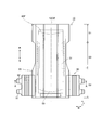
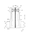
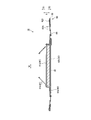
図1は、本実施形態に係る吸収性物品10を肌面側から見た平面図であり、図2は、実施形態に係る吸収コア30を肌面側から見た平面図である。図3は、図1に示すA-A線に沿った断面図である。図1及び図2に示す平面図は、吸収性物品10を皺が形成されない状態まで伸張させた伸長状態を示している。本実施の形態の吸収性物品10は、展開型の大人用の吸収性物品であるが、これに限定されない。吸収性物品10は、子供用の吸収性物品であってもよい。
吸収性物品10は、互いに直交する前後方向L及び幅方向Wを有する。前後方向Lは、身体前側と身体後側とに延びる方向によって規定される。言い換えると、前後方向Lは、展開された吸収性物品10において前後に延びる方向である。また、吸収性物品10は、前後方向Lと幅方向Wの両方に直交する厚さ方向Tを有する。厚さ方向Tは、着用者側に向かう肌面側T1と、着用者から離れる側の非肌面側T2と、に延びる。本明細書において、「肌面側」は、使用中に着用者の肌に面する側に相当する。「非肌面側」は、使用中に着用者の肌とは反対に向けられる側に相当する。
吸収性物品10は、前胴回り域S1と、後胴回り域S2と、股下域S3と、を有する。前胴回り域S1は、使用時に着用者の身体前側に面する。後胴回り域S2は、使用時に着用者の身体後側に面する。股下域S3は、前胴回り域S1と後胴回り域S2との間に位置し、使用時に着用者の股下に配置される。股下域S3は、吸収コア30によって規定できる。具体的には、くびれ部31を有する吸収コア30においては、吸収コア30のくびれ部31が形成された領域が、股下域S3の前後方向Lの領域となる。くびれ部31を有しない吸収コア30においては、吸収コア30の前後方向の長さを三等分したうちの中央の領域が、股下域S3の前後方向Lの領域となる。本実施の形態では、吸収コア30のくびれ部31の前端縁が、股下域S3と前胴回り域S1の境界を規定し、吸収コアのくびれ部31の後端縁が、股下域S3と後胴回り域S2の境界を規定している。
吸収性物品10は、脚回り開口部65を有する。脚回り開口部65は、吸収性物品の本体部(吸収性物品において後述する止着部材90を除いた部分)の外側縁において幅方向Wの内側に凹んだ部分である。なお、本実施の形態において外側縁は、幅方向の外側の端縁であり、内側縁は、幅方向の内側の端縁である。
吸収性物品10は、少なくとも股下域S3に配置された吸収コア30を有する。吸収コア30は、股下域S3から前胴回り域S1及び後胴回り域S2へ延びていてよい。吸収コア30は、例えば粉砕パルプもしくは高吸収性ポリマー(SAP)、又はこれらの混合物を含む吸収材料の積層体であってよい。吸収性物品10は、吸収コア30と、コアラップ(図示せず)と、を含む吸収体を有してよい。コアラップは、吸収コア30の肌面側と非肌面側を覆うように配置され、例えば、ティッシュや不織布シートであってよい。
吸収性物品10は、吸収コア30の肌面側T1に位置する肌面シート41と、吸収コア30の非肌面側T2に位置する非肌面シート42と、を有してよい。肌面シート41は、表面シート41aと、サイドシート41bと、を有してよい。表面シート41aは、液透過性を有し、吸収コア30の少なくとも幅方向Wの中心を覆うように配置されてよい。サイドシート41bは、疎水性を有する不織布からなり、吸収コア30の幅方向Wの中心よりも幅方向Wの外側において、幅方向Wにおける表面シート41aの両側部を覆うように配置されてよい。非肌面シート42は、液不透過性を有し、吸収コア30よりも非肌面側に設けられてよい。非肌面シート42は、液不透過性のバックフィルム42aと、バックフィルム42aの非肌面側T2に配置されたバック不織布42bと、を有してよい。
吸収性物品10は、後胴回り域S2の幅方向Wの両外側部に設けられた止着部材90を有してよい。図4は、図1に示す止着部材90の拡大平面図である。止着部材90は、前胴回り域S1に設けられたターゲット領域80に止着可能に構成されている。止着部材90は、後胴回り域S2において本体部から幅方向の両外側にそれぞれ延出している。より詳細には、止着部材90は、肌面シート41の外側縁及び非肌面シート42の外側縁から幅方向の外側に延出している。止着部材90は、幅方向の両側にそれぞれ配置されており、吸収性物品の幅方向の中心である物品幅中心10CWに対する線対称であってもよい。
止着部材90は、後胴回り域S2の肌面シート41及び非肌面シート42に接合されるベース部95と、ベース部95に固定された第1タブ91及び第2タブ92を有する。ベース部95は、幅方向に伸縮可能な伸縮部95Aを有していてもよい。伸縮部95Aを有することにより、第1タブ91と第2タブ92を異なる方向や位置に調整して止着し易くなる。
第1タブ91と第2タブ92は、前後方向Lに並んで配置されている。使い捨ておむつの展開状態において、第2タブ92は、第1タブ91よりも前側に配置されている。図6に示すように、使い捨ておむつの装着状態では、第2タブ92は、第1タブ91よりも後側に配置される。なお、第1タブ91と第2タブ92は、ベース部95と一体化していてもよい。また、第1タブ91と第2タブ92は、部分的に連なっていてもよい。第1タブ91は、ターゲット領域80に止着する第1係合部913を有する。第2タブ92は、ターゲット領域80に止着する第2係合部923を有する。
第1タブ91は、吸収性物品の展開状態(図1及び図4参照)における第1タブ91の幅方向の外端縁に位置する第1外端縁911と、第1タブ91の第1外端縁911に交差し、かつ幅方向に延びる第1交差縁912と、を有する。第1交差縁912は、第1外端縁911の前端縁911Fから幅方向の内側に延びる前第1交差縁F912と、第1外端縁911の後端縁911Rから幅方向の内側に延びる後第1交差縁R912と、を有する。
第2タブ92は、吸収性物品の展開状態における第2タブ92の幅方向の外端縁に位置する第2外端縁921と、第2タブ92の第2外端縁921に交差し、かつ幅方向に延びる第2交差縁922と、を有する。第2交差縁922は、第2外端縁921の前端縁921Fから幅方向の内側に延びる前第2交差縁F922と、第2外端縁921の後端縁921Rから幅方向の内側に延びる後第2交差縁R922と、を有する。第1交差縁912及び第2交差縁922は、幅方向に延びていればよく、幅方向に平行に延びる構成のみならず、幅方向に対して傾斜する構成も含む。
図2に示すように、ターゲット領域80は、装着時に、止着部材の第1係合部913及び第2係合部923が止着される領域である。ターゲット領域80は、フック部材としての係合部が止着するループ部材を有する領域であってもよいし、非肌面シート42の全面に係合部が係合可能な構成にあっては、前胴回り域の全体に亘って設けられていてよい。本実施の形態の係合部は、バック不織布42bに止着可能に構成されており、ターゲット領域80は、バック不織布42bが配置された領域となる。しかし、止着部材90を適切な位置に止めるためには、一定の範囲に止着部材90を止めることが好ましく、本実施の形態のターゲット領域80には、止着部材90を止める位置の目印となる目印部が設けられている。目印部は、吸収性物品の非肌面側から視認可能に構成されている。目印部は、バックフィルム42aに印刷されていてもよいし、バック不織布42bに印刷されていてもよい。
図5は、図2に示す目印部の拡大平面図である。目印部は、第1目印部51と、第2目印部52と、を有する。第2目印部52は、第1目印部51よりも後側に位置する。第1目印部51と第2目印部52は、前後方向Lに並んで配置されている。第1目印部51と第2目印部52は、一部重なっていてもよいし、離間していてもよい。第1目印部51は、第1タブ91の止着位置の目印となる。第1目印部51は、第1外端縁911に相似する第1外端図柄511と、第1交差縁912に相似する第1交差図柄512と、を有する。第1交差図柄512は、前第1交差縁F912に相似する前第1交差図柄F512と、後第1交差縁R912に相似する後第1交差図柄R512と、のうち少なくとも一方を有してよい。前第1交差図柄F512は、後第1交差図柄R512よりも後側に位置している。第1外端図柄511と第1交差図柄512は、連なっていてもよいし、離間してもよい。
第2目印部52は、第2タブ92の止着位置の目印となる。第2目印部52は、第2外端縁921に相似する第2外端図柄521と、第2交差縁922に相似する第2交差図柄522と、を有する。第2交差図柄522は、前第2交差縁F922に相似する前第2交差図柄F522と、後第2交差縁R922に相似する後第2交差図柄R522と、のうち少なくとも一方を有してよい。前第2交差図柄F522は、後第2交差図柄R522よりも後側に位置している。第2外端図柄521と第2交差図柄522は、連なっていてもよいし、離間してもよい。
第1目印部51は、第1外端図柄511と、第1交差図柄512と、を少なくとも有していればよく、第1タブ91の外形に相似しない非相似部分を有していてもよい。非相似部分は、例えば、タブの外形と角度や形状が異なる部分である。例えば、第1目印部51は、第1外端図柄511と第1交差図柄512との間に非相似部分を有していてもよいし、第1外端図柄511に非相似部分が連なっていてもよいし、第1交差図柄512に非相似部分が連なっていてもよい。同様に、第2目印部52は、第2外端図柄521と、第2交差図柄522と、を少なくとも有していればよく、第2タブ92の外形に相似しない非相似部分を有していてもよい。例えば、第2目印部52は、第2外端図柄521と第2交差図柄522との間に非相似部分を有していてもよいし、第2外端図柄521に非相似部分が連なっていてもよいし、第2交差図柄522に非相似部分が連なっていてもよい。
第1目印部51は、第1タブ91の止着位置を段階的に示すように幅方向Wに間隔を空けて複数設けられてよい。第1目印部51は、外側第1目印部51Xと、外側第1目印部51Xよりも幅方向Wの内側に配置された内側第1目印部51Yと、を有してよい。第1目印部51は、外側第1目印部51Xと内側第1目印部51Yの間に配置された中間第1目印部51Zを有してもよい。外側第1目印部51X、内側第1目印部51Y及び中間第1目印部51Zは、幅方向Wに離間していてもよいし、一部が連なっていてもよい。
第2目印部52は、第2タブ92の止着位置を段階的に示すように幅方向Wに間隔を空けて複数設けられてよい。第2目印部52は、外側第2目印部52Xと、外側第2目印部52Xよりも幅方向Wの内側に配置された内側第2目印部52Yと、を有してよい。第2目印部52は、外側第2目印部52Xと内側第2目印部52Yの間に配置された中間第2目印部52Zを有してもよい。外側第2目印部52X、内側第2目印部52Y及び中間第2目印部52Zは、幅方向Wに離間していてもよいし、一部が連なっていてもよい。
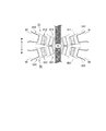
次いで、このように構成された吸収性物品10の止着部材90の止着態様について説明する。図6は、止着部材90がターゲット領域80に止着した状態を示した図である。具体的には、第1タブ91を外側第1目印部51Xに合わせて止着し、第2タブ92を外側第2目印部52Xに合わせて止着している。吸収性物品10を着用者に装着する際は、後胴回り域S2を着用者の背側に当て、かつ前胴回り域S1を着用者の腹側に当てた状態で、止着部材90を前胴回り域S1側に引き寄せ、左右それぞれの第1タブ91と、左右それぞれの第2タブ92と、をターゲット領域80に止着する。すなわち、第1タブ91と第2タブ92を有する吸収性物品10は、合計4つのタブをターゲット領域80に止着する操作を行う。このとき、装着者によっては、上下及び左右に複数のタブがあるため、適切な位置に止着部材90を配置できないことがあった。また、装着者によっては、第1タブ91を合わせる位置と第2タブ92を合わせる位置とが混同し、適切な位置に止着部材を配置できないことがあった。
本実施の形態の吸収性物品10は、目印部によって装着者がそれぞれのタブが止着される位置を把握できるように構成されている。具体的には、第1目印部51が第1タブ91の交差する2辺(第1外端縁及び第1交差縁)に相似する図柄であり、第2目印部52が第2タブ92の交差する2辺(第2外端縁及び第2交差縁)に相似する図柄である。装着者は、第1目印部51の2辺と第1タブの2辺を合わせることができ、第1タブ91を第1目印部51に合わせる部位を適切に把握できる。同様に、装着者は、第2目印部52の2辺と第2タブの2辺を合わせることができ、第2タブ92を第2目印部52に合わせる部位を適切に把握できる。また、第1目印部51と第2目印部52は、前後方向Lに並んで配置されているため、前後方向Lに並んだ第1タブ91と第2タブ92のそれぞれを止める位置を混同し難い。よって、それぞれのタブを適切な位置に止めることができる。
第1交差図柄512及び第2交差図柄522は、幅方向Wの内側に向かうにつれて前後方向Lにおいて互いに近づくように延びてよい。すなわち、第1交差図柄512は、幅方向Wの内側に向かって後側に延び、第2交差図柄522は、幅方向Wの内側に向かって前側に延びてよい。幅方向Wの内側に向かって互いに近づくように第1タブ91と第2タブ92を配置できる。第1タブ91の角度及び第2タブ92の角度もガイドでき、着用者の腹部の幅方向Wの中心に対して締め付ける力が強くなるように止着部材90を止着できる。
また、内側第1目印部51Yと内側第2目印部52Yとの前後方向Lの距離は、外側第1目印部51Xと外側第2目印部52Xとの前後方向Lの距離よりも短くなるように構成されてよい。タブの止着位置を段階的に選択し、物品幅中心10CWにより近い位置に止着する際に、第1タブ91と第2タブ92が近づくように配置でき、着用者の腹部の幅方向の中心に対して締め付ける力が強くなるように止着部材90を止着できる。
第1目印部51と第2目印部52は、前後方向Lに離間してよい。当該構成によれば、前後方向Lに並んで配置された第1タブ91と第2タブ92のそれぞれを止める位置をより区別し易くなり、それぞれのタブを適切な位置に止めることができる。なお、第1目印部51と第2目印部52が離間している部分があればよく、第1目印部51と第2目印部52の全体に亘って離間してもよいし、第1目印部51と第2目印部52の一部が離間してもよい。
第1目印部51と第2目印部52は、一部重なっており、装着順序が先のタブを示す目印部が欠けていてよい。すなわち、正しい止着順序で止着された状態で、装着者が見えるタブの状態を目印部によって示してよい。本実施の形態では、第1目印部51と第2目印部52が一部重なっており、第2目印部52は、第2タブ92の一部が欠けた形状であり、第1目印部51は、第1タブ91が欠けていない形状であって、第2目印部52に重なるように示されている。これによれば、装着者は、タブの正しい止着順序を把握でき、第1タブ91を第2タブ92に重ねるように止着する、すなわち、第2タブ92を止着し、次いで、第1タブ91を止着することを把握できる。
第1目印部51は、第1係合部913に相似する第1係合図柄513を有し、第2目印部52は、第2係合部923に相似する第2係合図柄523を有してよい。第1係合部913の位置を第1係合図柄513に直接合わせ、第2係合部923の位置を第2係合図柄523に直接合わせることができる。よって、タブの係合部をより適切な位置に止めることができる。第1係合図柄513と第2係合図柄523は、重なっていないことが好ましい。
第1目印部51は、第1タブ91の外形よりも大きくてよく、第2目印部52は、第1タブ91の外形よりも大きくてよい。具体的には、第1外端図柄511の長さは、第1外端縁911よりも長くてよい。第1交差図柄512の長さは、第1交差縁912よりも長くてよい。第2外端図柄521の長さは、第2外端縁921よりも長くてよい。第2交差図柄522の長さは、第2交差縁922よりも長くてよい。図6に示すように、第1目印部51に第1タブ91を合わせた状態で、第1目印部51の全体が第1タブ91によって覆われず、第2目印部52に第2タブ92を合わせた状態で、第2目印部52の全体が第2タブ92によって覆われない。よって、第1タブ91及び第2タブ92を止着した状態で第1目印部51及び第2目印部を視認し、タブの止着位置が適切か否かを判断することができる。必要に応じてタブの止着位置を直し、それぞれのタブを適切な位置に止めることができる。
より好適には、第1目印部51は、第1タブ91の外形よりも大きい部分と、第1タブ91の外形よりも小さい部分と、を有してよい。すなわち、第1目印部51は、第1タブ91の外縁をまたがる形状であってよい。同様に、第2目印部52は、第2タブ92の外形よりも大きい部分と、第2タブ92の外形よりも小さい部分と、を有してよい。すなわち、第2目印部52は、第2タブ92の外縁をまたがる形状であってよい。第1目印部51に重なるように第1タブ91を止着できる。加えて、止着した後にも第1目印部51が見えるため、第1タブ91の止着位置が適切か否かを判断することができる。同様に、第2目印部52に重なるように第2タブ92を止着できる。加えて、止着した後にも第2目印部52が見えるため、第2タブ92の止着位置が適切か否かを判断することができる。
目印部が段階的にタブの止着位置を示す形態にあっては、各目印部の見た目を異ならせてもよい。具体的には、外側第1目印部51Xは、内側第1目印部51Yに対する色差ΔEが3.0以上の第1識別部515を有してよい。第1識別部515は、中間第1目印部51Zに対する色差ΔEが3.0以上であってもよい。本実施の形態では、外側第1目印部51Xの第1係合図柄513、内側第1目印部51Yの第1係合図柄513、及び中間第1目印部51Zの第1係合図柄513のそれぞれが、第1識別部515として機能し、互いの色差が3.0以上異なる。外側第2目印部52Xは、内側第2目印部52Yに対する色差ΔEが3.0以上の第2識別部525を有してよい。第2識別部525は、中間第2目印部52Zに対する色差ΔEが3.0以上であってもよい。本実施の形態では、外側第2目印部52Xの第2係合図柄523、内側第2目印部52Yの第2係合図柄523、及び中間第2目印部52Zの第2係合図柄523のそれぞれが、第2識別部525として機能し、互いの色差が3.0以上異なる。
出願人が種々検討を重ねた結果、使用者は、一般的に色差ΔEが3.0以上であると、2つの領域を別の領域として認識し易いことがわかった。装着者は、着用者の体型等に応じて、外側第1目印部51Xと内側第1目印部51Yを選択するとともに、外側第2目印部52Xと内側第2目印部52Yを選択できる。このとき、装着者は、第1識別部515によって外側第1目印部51Xと内側第1目印部51Yを区別し易く、第2識別部525によって外側第2目印部52Xと内側第2目印部52Yを区別し易い。よって、外側第1目印部51Xと内側第1目印部51Yを混同することなく、着用者の体型に適した位置に第1タブ91を止め、外側第2目印部52Xと内側第2目印部52Yを混同することなく、着用者の体型に適した位置に第2タブ92を止めることができる。
なお、段階的にタブの止着位置を示す目印部の見た目を異ならせる他の形態としては、各目印部の柄を異ならせてもよいし、線の太さや形状を異ならせてもよい。また、外側第1目印部51Xの第1識別部と外側第2目印部52Xの第2識別部は、同じ色又は絵柄であってもよいし、内側第1目印部51Yの第1識別部と外側第2目印部52Xの第2識別部は、同じ色又は絵柄であってもよい。この構成によれば、第1タブと第2タブを異なる段階(例えば、外側第1目印部51Xと内側第2目印部52Y)に止着する操作間違いをし難く、第1タブと第2タブを同じ段階(例えば、外側第1目印部51Xと外側第2目印部52X)に止着し易い。
第1目印部51は、物品幅中心10CWに対する両側にそれぞれ配置され、第2目印部52は、物品幅中心10CWに対する両側にそれぞれ配置されている。装着者は、物品幅中心10CWの両側に左右のタブをそれぞれ止着できる。第1目印部51及び第2目印部52は、物品幅中心10CWに対して線対称であってよい。左右のタブを対称に止着できる。第1目印部51と第2目印部52の間には、前後方向に延びる中心目印部55が設けられていてもよい。中心目印部55を身体の中心に合わせることにより、より適した位置に吸収性物品10を装着できる。
第1目印部51及び第2目印部52の少なくとも一方は、吸収コアと30重なる領域に配置されてよい。第1タブ91及び第2タブ92の少なくとも一方を止着することにより、吸収コア30を押さえることができる。吸収コア30の密着性を高め、漏れを抑制できる。
第1目印部51及び第2目印部52は、吸収コア30の前端縁30Fよりも後側に配置されていてもよい。または、第1目印部51及び第2目印部52の少なくとも一方は、吸収コア30の前端縁30Fを跨がっていてもよい。当該構成によれば、第1タブ91及び第2タブ92の少なくとも一方を止着することにより、吸収コア30の前端縁を押さえることができる。吸収コア30の密着性を高めるとともに、吸収コア30の前端縁30Fが身体から浮き上がることによる漏れを抑制できる。
第1交差図柄512は、吸収コア30の前端縁30Fに沿って延びてよい。本実施の形態の吸収コア30の前端縁30Fは、幅方向Wの内側に向かって後側に延びている。すなわち、吸収コア30の前端縁30Fは、物品幅中心10CWに向かって後側に湾曲している。第1交差図柄512は、幅方向Wの内側に向かって後側に延びてよい。第1目印部51の第1交差図柄512に沿って第1タブ91が止着されることにより、吸収コア30の前端縁30Fの形状に沿うように吸収コア30を押さえることができる。吸収コア30の前端縁30Fが身体から浮き上がることによる漏れを抑制できる。
上述の実施形態を用いて本発明について詳細に説明したが、当業者にとっては、本発明が本明細書中に説明した実施形態に限定されるものではないということは明らかである。本発明は、特許請求の範囲の記載により定まる本発明の趣旨及び範囲を逸脱することなく修正及び変更態様として実施することができる。したがって、本明細書の記載は、例示説明を目的とするものであり、本発明に対して何ら制限的な意味を有するものではない。
なお、2019年2月18日に出願された日本国特許出願第2019-026913号の全内容が、参照により、本明細書に組み込まれる。
本発明によれば、第1タブと第2タブを有する吸収性物品において、第1タブと第2タブをそれぞれ適切な位置に装着できる吸収性物品を提供できる。
10:吸収性物品、10CW:物品幅中心、30:吸収コア、51:第1目印部、51X:外側第1目印部、51Y:内側第1目印部、511:第1外端図柄、512:第1交差図柄、513:第1係合図柄、515:第1識別部、52:第2目印部、52X:外側第2目印部、52Y:内側第2目印部、521:第2外端図柄、522:第2交差図柄、523:第2係合図柄、525:第2識別部、80:ターゲット領域、90:止着部材、91:第1タブ、911:第1外端縁、912:第1交差縁、913:第1係合部、92:第2タブ、921:第2外端縁、922:第2交差縁、923:第2係合部、S1:前胴回り域、S2:後胴回り域、S3:股下域、L:前後方向、T:厚さ方向、T1:肌面側、T2:非肌面側、W:幅方向
Claims (9)
- 互いに直交する前後方向及び幅方向と、
前記前後方向の中央を含む股下域、前記股下域よりも前側に位置する前胴回り域及び前記股下域よりも後側に位置する後胴回り域と、
少なくとも前記股下域に配置された吸収コアと、
前記後胴回り域において前記幅方向の外側に延出した止着部材と、
前記前胴回り域において前記止着部材が止着するターゲット領域と、を有し、
前記止着部材は、前記ターゲット領域に止着する第1係合部を有する第1タブと、前記第1タブよりも前側に位置し、前記ターゲット領域に止着する第2係合部を有する第2タブと、を有する吸収性物品であって、
前記ターゲット領域には、第1目印部と、前記第1目印部よりも後側に位置する第2目印部と、が設けられており、
前記第1目印部は、前記吸収性物品の展開状態における前記第1タブの前記幅方向の外端縁に位置する第1外端縁に相似する第1外端図柄と、前記第1タブの前記第1外端縁に交差し、かつ前記幅方向に延びる第1交差縁に相似する第1交差図柄と、を有し、
前記第2目印部は、前記展開状態における前記第2タブの前記幅方向の外端縁に位置する第2外端縁に相似する第2外端図柄と、前記第2タブの前記第2外端縁に交差し、かつ前記幅方向に延びる第2交差縁に相似する第2交差図柄と、を有し、
前記第1目印部と前記第2目印部は、前記前後方向に並んで配置されている、吸収性物品。 - 前記第1交差図柄及び前記第2交差図柄は、前記幅方向の内側に向かうにつれて前記前後方向において互いに近づくように延びている、請求項1に記載の吸収性物品。
- 前記第1目印部と前記第2目印部は、前記前後方向に離間している、請求項1又は請求項2に記載の吸収性物品。
- 前記第1目印部及び前記第2目印部の少なくとも一方は、前記吸収コアと重なる領域に配置されている、請求項1から請求項3のいずれか1項に記載の吸収性物品。
- 前記第1目印部及び前記第2目印部の少なくとも一方は、前記吸収コアの前端縁を跨がっている、請求項4に記載の吸収性物品。
- 前記吸収コアの前端縁は、前記幅方向の内側に向かって後側に延びており、
前記第1交差図柄は、前記幅方向の内側に向かって後側に延びている、請求項1から請求項5のいずれか1項に記載の吸収性物品。 - 前記第1目印部は、前記第1係合部に相似する第1係合図柄を有し、
前記第2目印部は、前記第2係合部に相似する第2係合図柄を有する、請求項1から請求項6のいずれか1項に記載の吸収性物品。 - 前記第1目印部は、外側第1目印部と、前記外側第1目印部よりも前記幅方向の内側に配置された内側第1目印部と、を有し、
前記第2目印部は、外側第2目印部と、前記外側第2目印部よりも前記幅方向の内側に配置された内側第2目印部と、を有し、
前記外側第1目印部は、前記内側第1目印部に対する色差ΔEが3.0以上の第1識別部を有し、
前記外側第2目印部は、前記内側第2目印部に対する色差ΔEが3.0以上の第2識別部を有する、請求項1から請求項7のいずれか1項に記載の吸収性物品。 - 前記第1外端図柄の長さは、前記第1外端縁よりも長く、
前記第1交差図柄の長さは、前記第1交差縁よりも長く、
前記第2外端図柄の長さは、前記第2外端縁よりも長く、
前記第2交差図柄の長さは、前記第2交差縁よりも長い、請求項1から請求項8のいずれか1項に記載の吸収性物品。
Priority Applications (1)
| Application Number | Priority Date | Filing Date | Title |
|---|---|---|---|
| CN202080011280.XA CN113365591B (zh) | 2019-02-18 | 2020-02-12 | 吸收性物品 |
Applications Claiming Priority (2)
| Application Number | Priority Date | Filing Date | Title |
|---|---|---|---|
| JP2019026913A JP7174643B2 (ja) | 2019-02-18 | 2019-02-18 | 吸収性物品 |
| JP2019-026913 | 2019-02-18 |
Publications (1)
| Publication Number | Publication Date |
|---|---|
| WO2020170899A1 true WO2020170899A1 (ja) | 2020-08-27 |
Family
ID=72144047
Family Applications (1)
| Application Number | Title | Priority Date | Filing Date |
|---|---|---|---|
| PCT/JP2020/005254 Ceased WO2020170899A1 (ja) | 2019-02-18 | 2020-02-12 | 吸収性物品 |
Country Status (3)
| Country | Link |
|---|---|
| JP (1) | JP7174643B2 (ja) |
| CN (1) | CN113365591B (ja) |
| WO (1) | WO2020170899A1 (ja) |
Cited By (2)
| Publication number | Priority date | Publication date | Assignee | Title |
|---|---|---|---|---|
| DE102023124235A1 (de) * | 2023-09-08 | 2025-03-13 | Paul Hartmann Ag | Inkontinenzwindel mit landemarkierungszonen |
| WO2025100423A1 (ja) * | 2023-11-10 | 2025-05-15 | ユニ・チャーム株式会社 | 吸収性物品 |
Families Citing this family (1)
| Publication number | Priority date | Publication date | Assignee | Title |
|---|---|---|---|---|
| JP7865796B2 (ja) * | 2022-06-14 | 2026-05-26 | ユニ・チャーム株式会社 | 吸収性物品及び吸収性物品群 |
Citations (5)
| Publication number | Priority date | Publication date | Assignee | Title |
|---|---|---|---|---|
| US4662875A (en) * | 1985-11-27 | 1987-05-05 | The Procter & Gamble Company | Absorbent article |
| JP2003111798A (ja) * | 2001-10-04 | 2003-04-15 | Daio Paper Corp | 使い捨て紙おむつ |
| JP2008168115A (ja) * | 2006-12-14 | 2008-07-24 | Kao Corp | 使い捨ておむつ |
| JP2012050575A (ja) * | 2010-08-31 | 2012-03-15 | Livedo Corporation | 使い捨ておむつ及びファスニング部の製造方法 |
| JP2016032589A (ja) * | 2014-07-31 | 2016-03-10 | ユニ・チャーム株式会社 | 吸収性物品 |
Family Cites Families (5)
| Publication number | Priority date | Publication date | Assignee | Title |
|---|---|---|---|---|
| US6045543A (en) * | 1997-11-05 | 2000-04-04 | Kimberly-Clark Worldwide, Inc. | Alignment indicators for use with personal care articles |
| JP5328168B2 (ja) * | 2008-02-04 | 2013-10-30 | ユニ・チャーム株式会社 | 着用物品 |
| JP5975810B2 (ja) * | 2012-09-12 | 2016-08-23 | 花王株式会社 | 使い捨ておむつ |
| CN203089559U (zh) * | 2012-12-28 | 2013-07-31 | 尤妮佳股份有限公司 | 一次性尿布 |
| JP5466328B1 (ja) * | 2013-09-10 | 2014-04-09 | ユニ・チャーム株式会社 | 吸収性物品 |
-
2019
- 2019-02-18 JP JP2019026913A patent/JP7174643B2/ja active Active
-
2020
- 2020-02-12 CN CN202080011280.XA patent/CN113365591B/zh active Active
- 2020-02-12 WO PCT/JP2020/005254 patent/WO2020170899A1/ja not_active Ceased
Patent Citations (6)
| Publication number | Priority date | Publication date | Assignee | Title |
|---|---|---|---|---|
| US4662875A (en) * | 1985-11-27 | 1987-05-05 | The Procter & Gamble Company | Absorbent article |
| US4662875B1 (ja) * | 1985-11-27 | 1989-04-18 | ||
| JP2003111798A (ja) * | 2001-10-04 | 2003-04-15 | Daio Paper Corp | 使い捨て紙おむつ |
| JP2008168115A (ja) * | 2006-12-14 | 2008-07-24 | Kao Corp | 使い捨ておむつ |
| JP2012050575A (ja) * | 2010-08-31 | 2012-03-15 | Livedo Corporation | 使い捨ておむつ及びファスニング部の製造方法 |
| JP2016032589A (ja) * | 2014-07-31 | 2016-03-10 | ユニ・チャーム株式会社 | 吸収性物品 |
Cited By (2)
| Publication number | Priority date | Publication date | Assignee | Title |
|---|---|---|---|---|
| DE102023124235A1 (de) * | 2023-09-08 | 2025-03-13 | Paul Hartmann Ag | Inkontinenzwindel mit landemarkierungszonen |
| WO2025100423A1 (ja) * | 2023-11-10 | 2025-05-15 | ユニ・チャーム株式会社 | 吸収性物品 |
Also Published As
| Publication number | Publication date |
|---|---|
| CN113365591A (zh) | 2021-09-07 |
| JP2020130540A (ja) | 2020-08-31 |
| JP7174643B2 (ja) | 2022-11-17 |
| CN113365591B (zh) | 2022-11-08 |
Similar Documents
| Publication | Publication Date | Title |
|---|---|---|
| JP5627978B2 (ja) | 使い捨て着用物品 | |
| ES2267684T3 (es) | Prenda interior desechable. | |
| US7887523B2 (en) | Disposable diaper | |
| EP1153587A1 (en) | Absorbent article | |
| JP7174643B2 (ja) | 吸収性物品 | |
| JP4002263B2 (ja) | 使い捨ておむつ | |
| JP6412861B2 (ja) | 吸収性物品 | |
| JP2012050717A (ja) | 使い捨て着用物品 | |
| JP2007202851A (ja) | 使い捨て吸収性物品 | |
| JP2006122456A (ja) | パンツ型紙おむつ | |
| CA2581326C (en) | Disposable wearing article | |
| JP6986494B2 (ja) | 吸収性物品 | |
| JP3217272U (ja) | 吸収性物品 | |
| JP5715865B2 (ja) | 紙おむつ | |
| KR20010095126A (ko) | 일회용 착용 물품 | |
| JP5958306B2 (ja) | テープ型使い捨ておむつ | |
| JP2014104292A (ja) | 使い捨てパンツ型おむつ | |
| JP6709843B2 (ja) | 吸収性物品 | |
| JP2020124423A (ja) | 使い捨て吸収性物品 | |
| JP6238404B2 (ja) | 吸収性物品 | |
| JP2007236434A (ja) | 使い捨ておむつ | |
| JP6118085B2 (ja) | 使い捨てパンツ型おむつ | |
| JP2008079642A (ja) | 吸収性物品 | |
| JP2014104290A (ja) | 使い捨てパンツ型おむつ | |
| JP6412896B2 (ja) | パンツ型使い捨ておむつ |
Legal Events
| Date | Code | Title | Description |
|---|---|---|---|
| 121 | Ep: the epo has been informed by wipo that ep was designated in this application |
Ref document number: 20759208 Country of ref document: EP Kind code of ref document: A1 |
|
| NENP | Non-entry into the national phase |
Ref country code: DE |
|
| 122 | Ep: pct application non-entry in european phase |
Ref document number: 20759208 Country of ref document: EP Kind code of ref document: A1 |