WO2020170765A1 - Fixing jig for linear friction welding and linear friction welding method - Google Patents
Fixing jig for linear friction welding and linear friction welding method Download PDFInfo
- Publication number
- WO2020170765A1 WO2020170765A1 PCT/JP2020/003710 JP2020003710W WO2020170765A1 WO 2020170765 A1 WO2020170765 A1 WO 2020170765A1 JP 2020003710 W JP2020003710 W JP 2020003710W WO 2020170765 A1 WO2020170765 A1 WO 2020170765A1
- Authority
- WO
- WIPO (PCT)
- Prior art keywords
- linear friction
- friction welding
- joined
- fixing
- fixing jig
- Prior art date
Links
Images


Classifications
-
- B—PERFORMING OPERATIONS; TRANSPORTING
- B23—MACHINE TOOLS; METAL-WORKING NOT OTHERWISE PROVIDED FOR
- B23K—SOLDERING OR UNSOLDERING; WELDING; CLADDING OR PLATING BY SOLDERING OR WELDING; CUTTING BY APPLYING HEAT LOCALLY, e.g. FLAME CUTTING; WORKING BY LASER BEAM
- B23K20/00—Non-electric welding by applying impact or other pressure, with or without the application of heat, e.g. cladding or plating
- B23K20/12—Non-electric welding by applying impact or other pressure, with or without the application of heat, e.g. cladding or plating the heat being generated by friction; Friction welding
Definitions
- the present invention relates to a linear friction welding fixing jig used for fixing a material to be welded in linear friction welding, and a linear friction welding method using the linear friction welding fixing jig.
- LFW Linear Friction Welding
- FSW Friction Stir Welding
- Patent Document 1 Japanese Patent Laid-Open No. 2018-122343
- a first step in which one member is brought into contact with the other member to form a bonded interface, and pressure is applied substantially perpendicularly to the bonded interface.
- the second step of repeatedly sliding one member and the other member on the same locus under the condition of applying the burrs from the interface to be bonded, and stopping the sliding to form the bonding surface.
- a characteristic linear friction welding method is disclosed, and it is possible to form a good joint even with a thin plate.
- the materials to be bonded are shaken (moved or tilted), and the bonding pressure and sliding force cannot be efficiently converted into the bonding temperature.
- the joining results obtained from the above may vary.
- the material to be joined is a thin plate, the problem becomes remarkable. That is, it is difficult to industrially apply linear friction welding in a situation where the materials to be welded cannot be reliably fixed.
- a substantially rectangular fixing hole provided in a direction substantially perpendicular to the side surface of the vibrating portion, and the fixing hole
- a fixing mechanism including a pressing portion that can move in one direction is generally used. Since the fixing mechanism changes the dimension in the fixing hole by moving the pressing portion and presses and fixes the material to be welded inserted in the fixing hole, in the method of fixing the material to be welded using this fixing mechanism, Only the pressing force applied from the pressing portion and the reaction force applied from the side surface of the fixing hole facing the pressing portion act to fix the materials to be joined.
- the fixing hole is formed with a large size so that the materials to be welded of various sizes can be inserted, there is no portion that abuts the material to be welded in the direction substantially orthogonal to the moving direction of the pressing portion. It is obvious that not only positioning of the materials to be joined in the fixing holes becomes difficult but also blurring is induced during joining, and there is still room for improvement.
- the present invention enables the material to be welded to be simply and surely fixed to the linear friction welding apparatus, and enables highly reproducible linear friction welding corresponding to the welding conditions.
- An object of the present invention is to provide a fixing jig for linear friction welding and a linear friction welding.
- the present invention is A first member provided with a pressed surface that receives a pressing force from a bonded material fixing portion of a linear friction welding device, and a valley formed by arranging two inclined surfaces opposite to each other on the opposite side of the pressed surface.
- a second member having contact surfaces that contact the inclined surface at both ends, Consisting of two said first members and two said second members, A fixing jig for linear friction welding, which is characterized by:
- the inclined surface of the first member and the contact surface of the second member are substantially parallel to each other.
- the material to be welded is uniquely and It is possible to accurately position and securely fix in a short time.
- the materials to be joined are held in contact with one of the second members and the other second member over a wide area and are sandwiched by these members, the blur in the height direction (sliding direction) due to sliding during joining is caused. Can be effectively suppressed.
- one material to be welded and the other material to be welded can be accurately brought into contact with each other without displacement and angular deviation before welding, and there is no gap over the entire area. Can form a good bonding interface. That is, when both materials to be welded are repeatedly slid on the same locus by the linear friction welding device, a substantially uniform temperature rise occurs over the entire joining interface, so that the joining temperature can be accurately controlled.
- the blurring (movement or inclination) of the joined materials due to the improper fixing is suppressed, and the joining pressure and the sliding force are efficiently joined. Can be converted to temperature. Therefore, it is possible to reduce the variation between the set joining condition and the joining result.
- the second member has a substantially truncated pyramid shape.
- the contact surface of the second member and the slope of the first member have the same angle, and the vertical dimension and the horizontal dimension are different.
- it can be used corresponding to a material to be joined having a certain size width.
- it is possible to prolong the life of the linear friction welding fixing jig without being repeatedly given the thermal influence during welding on only a part thereof.
- the area of the second member that contacts the material to be welded is larger than the pressed surface.
- the pressing force from the linear friction welding device is converted by approximately 90°, so that the area of the second member that abuts the material to be welded is larger than the surface to be pressed.
- the materials to be joined can be fixed more reliably and efficiently.
- the area of the second member is preferably twice or more the area of the pressed surface, more preferably three times or more, and most preferably four times or more.
- the first member and/or the second member is tool steel, heat resistant steel, cemented carbide, cermet, nickel base alloy, cobalt base alloy and titanium alloy. It is desirable to be formed of any one of the above materials. By using these materials for the first member and/or the second member, wear and shape change due to repeated use can be suppressed, and sufficient strength and dimensional accuracy can be ensured against temperature rise during joining. can do.
- the first member and/or the second member is preferably made of ceramics.
- the present invention is A method for joining one joined material and the other joined material, Fixing the one material to be joined and/or the other material to be joined to the linear friction welding device by the linear friction welding fixing jig according to any one of claims 1 to 5; A linear friction welding method is also provided.
- one of the materials to be welded and/or the other material to be welded is fixed to the linear friction welding apparatus using the fixing jig for linear friction welding of the present invention. And the material to be joined can be securely fixed. As a result, the stress applied from the linear friction welding device can be transmitted to the material to be welded without waste, and linear friction welding can be performed according to the set welding conditions (pressing force and vibration force on the material to be welded). You can
- the second step, And a third step of forming a bonded interface by stopping the sliding It is preferable that the pressure is set to be equal to or higher than the yield stress and equal to or lower than the tensile strength of the one joined material and/or the other joined material at a desired joining temperature.
- the welding temperature is controlled by setting the pressure during linear friction welding to a yield stress of one member and/or the other member at a desired joining temperature and equal to or less than the tensile strength. It has become clear that you can.
- the pressure during linear friction welding is made equal to or higher than the yield stress of the materials to be welded, discharge of burrs from the interface to be welded is started, and if the pressure is increased up to the tensile strength, the burrs will be discharged. It will be accelerated. Similar to the yield stress, the tensile strength at a specific temperature is substantially constant depending on the materials to be joined, so that the joining temperature corresponding to the set pressure can be realized.
- the pressure during linear friction welding it is preferable to set the pressure during linear friction welding to the yield stress of one member and/or the other member at a desired welding temperature.
- the discharge of burr starts at the moment when the pressure reaches the yield stress, which is more accurate than when the pressure is set to a higher value (with the tensile strength as the upper limit).
- a bonding temperature can be realized.
- the one joined material and/or the other joined material is a thin plate having a plate thickness of 3 mm or less.
- the applied pressure during linear friction welding is set to be equal to or higher than the yield stress of the thin plate (material to be welded) at the desired welding temperature, so that the heated and softened region is promptly discharged as burr. It is possible to prevent the softened portion (high temperature portion) from unnecessarily expanding due to heat conduction of frictional heat. In this case, the temperature at the position away from the bonded interface is lower than the temperature in the vicinity of the bonded interface (bonding temperature), and plastic deformation does not occur under the applied pressure. As a result, even if the plate thickness is 3 mm or less, its shape can be maintained during linear friction welding.
- the fixing tool for linear friction welding which fixes a to-be-joined material with respect to a linear friction welding apparatus simply and reliably and can implement highly reproducible linear friction welding corresponding to a joining condition, and A linear friction bond can be provided.
- FIG.3(a) is a side view of the 1st member 3 which carried out the front view of the end surface of the 1st member 3
- FIG.3(b) is FIG. 3A is a front view of the first member 3 in which a part of the arrow A in FIG. 3A is cross-sectionally viewed
- FIG. 3C is a bottom view of the first member 3 that is viewed in the arrow B in FIG. ..
- FIG.4(a) is a front view of the 2nd member 5
- FIG.4(b) shows the arrow C in FIG.4(a) second.
- FIG. 5(a) is a perspective view
- FIG. 5(b) is a side view.
- FIG. 6(a) is a perspective view
- FIG. 6(b) is a side view. ..
- FIG.7(a) is a perspective view
- FIG.7(b) is a side view
- FIG.8(a) is a schematic diagram which shows a mode that the fixing preparation body 101 is inserted in the fixing hole 52
- FIG.8(b) is a schematic view showing pressing of a material 53 to be joined by the linear friction joining fixing jig 1.
- FIG.9(a) is a perspective view
- FIG.9(b) is a side view
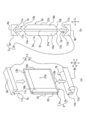
- FIG. 1 is a schematic diagram showing a situation during linear friction welding
- FIG. 2 is a schematic diagram showing an outline of a fixing jig 1 for linear friction welding according to the present embodiment.
- the direction in which the bonding pressure is applied is defined as X
- the direction substantially perpendicular to X and the sliding direction is defined as Y
- the sliding direction is defined as Z.
- linear friction welding the materials to be welded are brought into contact with each other in a linear motion while applying a predetermined welding pressure from opposite directions, and frictional heat generated at this time is used as a main heat source.
- Solid phase bonding The main methods used for linear friction welding here are a preliminary step in which one material to be joined and the other material to be joined are fixed to the linear friction welding device, and both materials are brought into contact with each other. And a second step of repeatedly sliding both materials to be joined on the same locus at the formed joint interface, and stopping the sliding at a predetermined timing to form a joint. And a third step.
- the fixing tool 1 for linear friction joining of the present embodiment includes two second members 5 (one second member 5a and the other second member 5b) that directly abut the joined material 53.
- a jig constituted by two first members 3 (one first member 3a and the other first member 3b) that sandwich the second member 5 between the first member 3 and the first member 3b.
- Each of these members is arranged between the device 51 and the device for use.
- the improvement of the joining preparation makes it possible to prevent the joined material 53 from being shaken due to improper fixing, so that the joining temperature can be easily controlled during the second step and the joined object can be stopped during the sliding stop in the third step. It is possible to prevent an inclination or the like from occurring between the materials 53. That is, the fixing jig 1 for linear friction welding according to the present embodiment provides a plurality of suitable effects for linear friction welding.
- the linear friction welding device 51 used in the present embodiment includes a fixing hole 52 into which the end of the material to be welded 53 opposite to the joining surface 61 is inserted into the vibrating portion, and a lower end (or an upper end) of the fixing hole 52.
- a fixing mechanism 55 for the material 53 to be joined which comprises a pressing portion 54 that moves up and down in the direction Z, and the material 53 to be joined inserted in the fixing hole 52 is pressed and fixed in the direction Z by the pressing portion 54.
- the pressing direction for fixing the joined material 53 is not limited to the above, and the direction Y may be adopted, for example.
- FIGS. 3 and 4. are diagrams showing the structure of the first member 3, and FIG. 3A is a side view of the first member 3 in which the end face of the first member 3 is viewed from the front.
- 3(b) is a front view of the first member 3 in which a part of the arrow A in FIG. 3(a) is cross-sectionally viewed, and FIG. 3(c) is an arrow in FIG. 3(a).
- 4(a) and 4(b) are views showing the structure of the second member 5
- FIG. 4(a) is a front view of the second member 5
- FIG. 4(b) is It is a side view of the second member 5 which shows the arrow C in FIG.
- the first member 3 is a valley formed by arranging a pressed surface 9 that receives a pressing force from the linear friction welding device 51 and two inclined surfaces 11 so as to face each other. And a valley portion 7 is formed on the opposite side of the pressed surface 9 in the pressing force application direction (downward in the direction Z in FIG. 3A). ..
- a substantially smooth pressed surface that abuts the pressing portion 9 of the linear friction welding device 51 or the upper side surface of the fixing hole 52 that faces the pressing portion 9. 9 and a valley portion 7 formed by two inclined surfaces 11 which are downwardly inclined in the direction Z and toward both sides in the direction Y from approximately the center of the pressed surface 9 and the direction Y of the pressed surface 9. It has a side surface shape composed of a vertical plane that connects both ends and both ends of the two inclined surfaces 11 in the direction Y in the direction Z (in particular, refer to FIG. 3A). It is a substantially columnar body extruded by a predetermined size (see particularly FIGS. 3B and 3C).
- the vicinity of the apex (the bottom of the valley 7) formed by the two inclined surfaces 11 may be formed in an arc shape in the range of 2.5R to 5R to improve the cleaning property and the maintainability.
- the side surfaces of both ends of the first member 3 are formed parallel and smooth with respect to the direction Z, but depending on the aspect of the linear friction welding device 51 and the shape and size of the material 53 to be welded. Different shapes may be adopted as appropriate.
- the angle ⁇ 1 of the inclined surface 11 with respect to the direction Z is preferably set in the range of 30 to 60 degrees in order to ensure good sliding between the first member 3 and the second member 5 described later. Further, for the same reason, it is preferable that the inclined surface 11 has a surface roughness that suppresses the generation of frictional resistance without unevenness.
- the substantially straight inclined surface 11 without distortion is adopted, but it may be an arc having a gentle curvature, for example.
- the second member 5 is formed with contact surfaces 13 that contact the inclined surface 11 of the first member 3 at both ends.
- the abutting inclined surface 11 and the abutting surface 13 are substantially parallel to each other.
- a substantially rectangular fixing surface 15 that faces the direction Y and directly abuts on the joined material 53, and both end portions of the fixing surface 15 in at least the direction Z.
- the member is composed of a slope 19 that is inclined in the opposite direction to the fixed surface 15 and a parallel surface 21 that is parallel to the fixed surface 15 and faces the opposite direction.
- the angle ⁇ 2 of the contact surface 13 with respect to the fixed surface 15 is in the range of 30 to 60 degrees and is the same as the angle ⁇ 1 of the inclined surface 11 with respect to the direction Z (vertical surface) described above, and is good with the first member 3 described above. It is desirable to secure a good slide. Further, like the surface of the inclined surface 11, the contact surface 13 preferably has a surface roughness that suppresses the generation of frictional resistance without unevenness.
- the second member 5 has a substantially truncated pyramid shape.
- the second member 5 of the present embodiment is provided with the slopes 19 at both ends in the direction X as described above, and is formed into a substantially quadrangular truncated pyramid shape as a whole.
- the material 53 to be bonded can be fixed up to the vicinity of the bonding surface 61, and more stable bonding can be performed.
- the angle of the inclined surface 19 with respect to the fixed surface 15 is the same as the angle ⁇ 2 of the inclined surface 13 with respect to the fixed surface 15, the inclined surface 19 is slidably engaged with the inclined surface 11 of the first member 3 like the contact surface 13. Can be stopped. Therefore, for example, if the second member 5 is formed so that the dimension in the Z direction and the dimension in the X direction are different from each other, depending on the size of the material 53 to be bonded, the material 53 to be bonded 53 can be made more from the Z direction or the X direction of the second member 5. It becomes possible to select and use a direction suitable for fixing, and it is possible to deal with the joined material 53 having a certain size width with one linear friction joining fixing jig 1.
- the first member 3 and/or the second member 5 is preferably formed of any material of tool steel, heat resistant steel, cemented carbide, cermet, nickel base alloy, cobalt base alloy and titanium alloy.
- the first member 3 and the second member 5 described above are required not only to have high strength and wear resistance, but also because they are used for joining the materials 53 to be joined of various metal materials, heat influence from the vicinity of the joining surface 61 Highly likely to receive.
- the inclined surface 11, the contact surface 13, the inclined surface 19 and the like are slidably locked to each other, it is necessary to process them to have a corresponding surface roughness.
- first member 3 and/or the second member 5 is formed of any one of tool steel, cemented carbide, cermet, nickel-based alloy and cobalt-based alloy, mechanical properties are sufficiently secured and during bonding. It can withstand the heat effect of. In addition, precision processing can be performed relatively easily.
- FIGS. 5 to 7 are diagrams showing a method of bringing the second member 5 into contact with the material 53 to be joined, FIG. 5(a) is a perspective view, and FIG. 5(b) is a side view. Is.
- FIGS. 6A and 6B are diagrams showing a method of bringing the first member 3 into contact with the second member 5 that has come into contact with the material 53 to be joined, and FIG.
- FIG. 6A is a perspective view.
- FIG. 6B is a side view.
- 7(a) and 7(b) are diagrams showing the fixing jig 1 for linear friction welding and the material 53 to be joined after abutting, and FIG. 7(a) is a perspective view and FIG. b) is a side view.
- the second member 5 of the linear friction welding fixing jig 1 is brought into contact with the workpiece 53.
- the two surfaces facing the direction Y of the material 53 to be joined are the first surface 57 and the second surface 59, and the member contacting the first surface 57 is in contact with one of the second member 5a and the second surface.
- the member is the other second member 5b.
- the material 53 to be welded and the fixing jig 1 for linear friction welding maintain the illustrated directionality (direction X, direction Y, and direction Z) unless otherwise specified in the text.
- the second surface 5a is brought into contact with the material 53 to be bonded while the fixed surface 15a is opposed to the first surface 57 of the material 53 to be bonded, and the fixed surface 15b is opposed to the second surface 59 while the other is opposed to the second surface 59.
- the second member 5b is brought into contact with the material 53 to be joined.
- the bonding surface 61 of the material 53 to be bonded is projected in the direction Y by a predetermined amount from the slopes 19a and 19b.
- the protrusion amount may be appropriately determined according to the size of the material 53 to be bonded, the bonding conditions, and the like.
- the first member 3 is brought into contact with the material 53 and the second member 5 that have been brought into contact with each other in the above procedure.
- the member to be brought into contact with the upper side of the joined material 53 and the second member 5 in the direction Z is one first member 5a, and the member to be brought into contact with the lower side is the other second member 5b.
- the valley portion 7a of the one first member 3a is opposed to the contact surface 13a of the one second member 5a and the contact surface 13b of the other second member 5b facing upward in the direction Z.
- the abutting surface 13a and the abutting surface 13b are brought into contact with the two inclined surfaces 11a forming 7a, respectively.
- the valley portion 7b of the other first member 3b is opposed to the contact surface 13a of the one second member 5a and the contact surface 13b of the other second member 5b facing downward in the direction Z.
- the abutting surface 13a and the abutting surface 13b are brought into contact with and locked by the two inclined surfaces 11b forming the valley portion 7b.
- the joined material 53 is supported by being abutted in the direction Y by the one second member 5a and the other second member 5b, and further, the one second member 5a and the other second member. 5b above and below in the direction Z, the substantially first fixing preparation body 101 that is locked by the first member 3a on one side and the first member 3b on the other side, and is made up of the joined material 53, the first member 3, and the second member 5. (See especially FIGS. 7A and 7B).
- FIGS. 8A and 8B are views showing a method of fixing the fixing preparation body 101 by the linear friction welding device 51
- FIG. 8A shows a state in which the fixing preparation body 101 is inserted into the fixing hole 52.
- FIG.8(b) is a schematic diagram which shows the pressing of the to-be-joined material 53 by the fixing jig 1 for linear friction welding.
- the fixing preparation body 101 configured by the above procedure is inserted into the fixing hole 52 of the fixing mechanism 55 included in the linear friction welding device 51. More specifically, the fixing preparation body 101 is inserted into the fixing hole 52 with the opposite side of the joining surface 61 facing the fixing hole 52, and the pressed surface 9a of the one first member 3a is fixed to the fixing hole 52. Abuts on the upper end in the direction Z.
- the pressing portion 54 provided in the fixing mechanism 55 is moved from the lower side to the upper side in the direction Z to press the fixing preparation body 101 inserted into the fixing hole 52.
- the fixing preparation body 101 is pressed between the upper end of the fixing hole 52 and the pressing portion 54, and the pressed surface 9a of the one first member 3a and the other first member 3b.
- the pressed surface 9b receives the pressing force P1 acting in the direction Z.
- the pressing force P1 presses the first member 3a on one side and the first member 3b on the other side toward the material 53 to be bonded, while the inclined surface 11a of the first member 3a on one side and the inclined surface 11b of the first member 3b on the other side. Via the contact surface 13a of the one second member 5a and the contact surface 13b of the other second member 5b. At the time of the transmission, a part of the pressing force P1 changes the action direction and generates a pressing force P2 that acts on the joined material 53 in a substantially oblique direction.
- the first member 3 and the second member 5 are locked to each other by abutting the slanted inclined surface 11 and the abutting surface 13, so that the first member 3a located on the upper side.
- the other first member 3b positioned below receives the pressing force P1 and the pressing force P2, which face each other, and is pressed in the direction Z toward the joined material 53 side, whereby the one second member 5a.
- the other second member 5b is substantially compressed, and the contact surface 13a and the contact surface 13b that are in contact with the two inclined surfaces 11a that form the valley portion 7a are upward and in the direction Z along their inclinations.
- the contact surface 13a and the contact surface 13b which are slid to the joined material 53 side of Y and contact the two inclined surfaces 11b forming the valley portion 7b, are downward in the direction Z along their own inclinations. Further, each slides in the direction Y toward the joined material 53, and the pressing force P3 acting in the direction Y acts on the joined material 53.
- the force applied from the fixing mechanism 55 to the fixing preparation 101 in the direction Z from above to below and from below to above is in the same direction.
- the pressing force P1 acting (two directions up and down in the direction Z with respect to the material 53 to be joined), and the pressing force P2 acting in a substantially oblique direction when transmitting the pressing force P1 from the first member 3 to the second member 5
- the material to be welded 53 pressed by the force in the eight directions is automatically and accurately positioned in the approximate center of the direction Y by the action of the pressing force P3, and further, in the directions X, Y, and by the action of all the pressing forces P1 to P3.
- the upper and lower end surfaces of the joined material 53 in the direction Z are not in contact with either the first member 3 or the second member 5, but the first surface 57 and the second surface 59 of the joined material 53 are one of the first surface.
- the fixing surface 15a of the second member 5a and the fixing surface 15b of the other second member 5b are in contact with each other over a wide area, and the end surface of the material 53 to be bonded opposite to the bonding surface 61 is directed in the direction X inside the fixing hole 52.
- the material 53 to be joined is sandwiched between the second member 5a on one side and the second member 5b on the other side in a wide area while being abutted against each other. It is possible to preferably prevent the shake in the direction Z to be performed.
- the second member 5 can be used while changing the direction of the second member 5 as appropriate, so that the linear friction welding fixing jig 1 does not have a repeated thermal effect on only a part thereof. The life can be properly extended.
- the material 53 to be welded (hereinafter, the reference numeral of the material to be welded will be omitted for convenience of description) is positioned and reliably fixed by the linear friction welding fixing jig 1, one of the materials to be welded and the other
- the materials to be welded can be accurately brought into contact with each other without displacement and distortion, and a good welding interface with no gap can be formed over the entire area. That is, when both the materials to be welded are repeatedly slid on the same locus by the linear friction welding device 51, a substantially uniform temperature rise occurs over the entire welding interface, so that the welding temperature can be accurately controlled.
- the sliding is repeated along the same locus while applying the joining pressure. Even during bonding, there is no blurring (movement or inclination) of the materials to be bonded due to improper fixing, and the bonding pressure and sliding force can be efficiently converted to the bonding temperature. Therefore, it is possible to preferably reduce the variation in the joining condition and the joining result due to the fixing condition of the materials to be joined.
- FIG. 9(a) and 9(b) are views showing the structure of another fixing jig 1001 for linear friction joining, FIG. 9(a) is a perspective view, and FIG. 9(b) is a side view. is there.
- the other fixing jig 1001 for linear friction welding has an optimized shape so that it can be used to fix the substantially cylindrical material 1053 to be welded.
- the linear friction welding fixing jig 1001 is also a jig including two first members 1003 and two second members 1005 as in the linear friction welding fixing jig 1 described above.
- the fixed surface 1015 of 1005 is provided with a recess 1007 having a substantially curved surface that matches the side surface shape of the material 1053 to be joined.
- the radius of the recess 1007 may be substantially the same as the radius of the material 1053 to be bonded, and may be formed in the second member 1005 to a depth such that both fixing surfaces 1015 do not abut when the material 1053 to be bonded is fixed. preferable. In addition, it is desirable that the recesses 1007 be formed so as not to be displaced with respect to each other at substantially the center in the direction Z of both the second members 1005.
- FIG. 10 shows an external photograph of the linear friction welding device.
- the yield stress is about 150 MPa.
- the pressure applied during linear friction welding was 250 MPa, which was higher than 150 MPa, the frequency of vibration was 15 Hz, and the amplitude was 2 mm to obtain a bonded body.
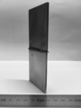
- FIG. 12 shows an external view photograph of the execution bonded body.
- FIG. 14 shows a state in which the material to be welded is fixed to the linear friction welding device.
- the stress of the linear friction welding device is applied only from above the welded device, but the stress is transmitted from the first member arranged above and below the welded material to the second member, and the welded material is strong from both sides. It is fixed to.
- Fig. 15 shows a macro photograph of a cross section in the vicinity of the bonding interface of the obtained bonded structure. No defects were found at the joint interface, indicating that a good joint was obtained.
- FIG. 16 shows a state in which the material to be welded is fixed to the linear friction welding device. Pads are arranged on the left and right of the materials to be joined, and the pressing force from the device is applied only from above the materials to be joined.
- Fig. 17 shows a cross-sectional macro photograph of the vicinity of the joint interface of the obtained comparative joint.
- the bonding conditions are the same as in the example, defects are formed at the bonding interface. The results suggest that the pressure and the vibration force applied during linear friction welding were not directly transmitted to the materials to be welded.
Abstract
Provided are a fixing jig for linear friction welding and a linear friction welding method with which it is possible to easily and reliably fix a welding material to a linear friction welding device and perform linear friction welding suitable to the welding conditions with high reproducibility. This fixing jig for linear friction welding is characterized by comprising: a first member having a pressed surface that receives the pressing force from a welding material fixing unit of the linear friction welding device and a valley part that is formed by two inclined surfaces disposed facing each other on the reverse side from the pressed surface; and a second member having, on two ends thereof, respective contact surfaces for contacting the inclined surfaces, wherein the fixing jig is constituted from two first members and two second members.
Description
本発明は線形摩擦接合において被接合材の固定に用いる線形摩擦接合用固定治具及び当該線形摩擦接合用固定治具を用いた線形摩擦接合方法に関する。
The present invention relates to a linear friction welding fixing jig used for fixing a material to be welded in linear friction welding, and a linear friction welding method using the linear friction welding fixing jig.
鋼やアルミニウム合金等の金属材料の高強度化に伴い、接合構造物の機械的特性を決定する接合部での強度低下が深刻な問題となっている。これに対し、近年、接合中の最高到達温度が被接合材の融点に達せず、接合部における強度低下が従来の溶融溶接と比較して小さい固相接合法が注目され、急速に実用化が進んでいる。
With the increase in strength of metal materials such as steel and aluminum alloys, the decrease in strength at the joint that determines the mechanical properties of the joint structure has become a serious problem. On the other hand, in recent years, the solid-state joining method, in which the maximum temperature reached during joining does not reach the melting point of the materials to be joined and the strength decrease in the joined part is smaller than that of conventional fusion welding, has attracted attention and is rapidly being put to practical use. It is progressing.
特に、金属部材同士を線形軌跡で摺動させる線形摩擦接合(LFW:Linear Friction Welding)は、摩擦攪拌接合(FSW:Friction Stir Welding)のようにツールを用いる必要がないことから、高融点金属にも容易に適用することができ、種々の産業における実用化が期待されている。
In particular, linear friction welding (LFW: Linear Friction Welding) in which metal members slide along a linear trajectory does not require the use of tools like friction stir welding (FSW: Friction Stir Welding). Can be easily applied and is expected to be put to practical use in various industries.
また、特許文献1(特開2018-122343号公報)には、一方の部材を他方の部材に当接させて被接合界面を形成する第一工程と、被接合界面に対して略垂直に圧力を印加した状態で、一方の部材と他方の部材とを同一軌跡上で繰り返し摺動させ、被接合界面からバリを排出させる第二工程と、摺動を停止して接合面を形成する第三工程と、を有し、一方の部材及び他方の部材の少なくとも一方を、板厚が3mm以下の薄板とし、圧力を、接合温度における薄板の降伏応力以上に設定してバリを排出させること、を特徴とする線形摩擦接合方法が開示されており、薄板であっても良好な継手の形成を可能としている。
Further, in Patent Document 1 (Japanese Patent Laid-Open No. 2018-122343), a first step in which one member is brought into contact with the other member to form a bonded interface, and pressure is applied substantially perpendicularly to the bonded interface. The second step of repeatedly sliding one member and the other member on the same locus under the condition of applying the burrs from the interface to be bonded, and stopping the sliding to form the bonding surface. A step of forming at least one of the one member and the other member as a thin plate having a plate thickness of 3 mm or less, and setting a pressure equal to or higher than the yield stress of the thin plate at the joining temperature to discharge the burr. A characteristic linear friction welding method is disclosed, and it is possible to form a good joint even with a thin plate.
しかしながら、従来の線形摩擦接合方法では、線形摩擦接合装置に対する被接合材の簡便かつ確実な固定方法が確立されておらず、スペーサ等を用いた不確実かつ煩雑な位置決めや装置が具備する固定機構による簡易な押圧のみで行われているため、二つの被接合材を当接した際に位置ズレ、角度ブレ、及びこれらに起因する隙間の発生等を招くことがあり、接合時の接合界面において不均一な温度上昇が発生し、再現性に問題があった。
However, in the conventional linear friction welding method, a simple and reliable fixing method of the material to be welded to the linear friction welding device has not been established, and uncertain and complicated positioning using a spacer or the like and a fixing mechanism provided in the device. Since it is performed only by simple pressing due to the above, there are cases where when two materials to be joined are brought into contact with each other, positional deviation, angular deviation, and the generation of gaps resulting from these may occur, and at the joining interface during joining. There was a problem of reproducibility due to uneven temperature rise.
また、上記被接合材の固定不良に起因して被接合材のブレ(移動や傾き)が発生し、接合圧力及び摺動力を効率的に接合温度に変換することができず、設定した接合条件から得られる接合結果にバラつきが生じる問題があった。特に、被接合材が薄板の場合は当該問題が顕著になる。即ち、確実な被接合材の固定が行えない状況では、産業的に線形摩擦接合を適用することが困難である。
Further, due to the improper fixing of the materials to be bonded, the materials to be bonded are shaken (moved or tilted), and the bonding pressure and sliding force cannot be efficiently converted into the bonding temperature. There is a problem in that the joining results obtained from the above may vary. In particular, when the material to be joined is a thin plate, the problem becomes remarkable. That is, it is difficult to industrially apply linear friction welding in a situation where the materials to be welded cannot be reliably fixed.
ここで、一般的な線形摩擦接合装置が具備する被接合材の固定機構に着目すると、加振部の側面に対して略垂直方向に設けられた略四角形状の固定穴と、当該固定穴の中で一方向に移動可能とした押圧部と、を具備した固定機構が一般的である。当該固定機構は押圧部を移動させることで固定穴内の寸法を変動し、固定穴に挿入した被接合材を押圧固定するものであるため、この固定機構を用いた被接合材の固定方法では、押圧部から印加される押圧力と当該押圧部に対向する固定穴の側面から印加される反力のみしか被接合材の固定に作用しない。
Here, paying attention to the fixing mechanism of the material to be welded which a general linear friction welding apparatus has, a substantially rectangular fixing hole provided in a direction substantially perpendicular to the side surface of the vibrating portion, and the fixing hole A fixing mechanism including a pressing portion that can move in one direction is generally used. Since the fixing mechanism changes the dimension in the fixing hole by moving the pressing portion and presses and fixes the material to be welded inserted in the fixing hole, in the method of fixing the material to be welded using this fixing mechanism, Only the pressing force applied from the pressing portion and the reaction force applied from the side surface of the fixing hole facing the pressing portion act to fix the materials to be joined.
また、固定穴は種々のサイズの被接合材を挿入可能にするため大きな寸法で形成されていることから、押圧部の移動方向と略直交する方向は被接合材と当接する部位がないため、固定穴内における被接合材の位置決めが困難になるばかりか、接合中においてもブレを誘発してしまうことは明らかであって、未だ改善する余地があった。
Further, since the fixing hole is formed with a large size so that the materials to be welded of various sizes can be inserted, there is no portion that abuts the material to be welded in the direction substantially orthogonal to the moving direction of the pressing portion. It is obvious that not only positioning of the materials to be joined in the fixing holes becomes difficult but also blurring is induced during joining, and there is still room for improvement.
以上のような従来技術における問題点に鑑み、本発明は、線形摩擦接合装置に対して簡便かつ確実に被接合材を固定し、接合条件に対応した再現性の高い線形摩擦接合の実施を可能とする線形摩擦接合用固定治具及び線形摩擦接合を提供することを目的とする。
In view of the above problems in the prior art, the present invention enables the material to be welded to be simply and surely fixed to the linear friction welding apparatus, and enables highly reproducible linear friction welding corresponding to the welding conditions. An object of the present invention is to provide a fixing jig for linear friction welding and a linear friction welding.
上記の課題を解決すべく、本発明は、
線形摩擦接合装置の被接合材固定部から押圧力を受ける被押圧面と、前記被押圧面の反対側に二つの傾斜面を対向配置して形成された谷部と、を備えた第一部材と、
前記傾斜面と当接する当接面を両端部に備えた第二部材と、を具備し、
二つの前記第一部材と二つの前記第二部材とから構成されること、
を特徴とする線形摩擦接合用固定治具、を提供する。 In order to solve the above problems, the present invention is
A first member provided with a pressed surface that receives a pressing force from a bonded material fixing portion of a linear friction welding device, and a valley formed by arranging two inclined surfaces opposite to each other on the opposite side of the pressed surface. When,
A second member having contact surfaces that contact the inclined surface at both ends,
Consisting of two said first members and two said second members,
A fixing jig for linear friction welding, which is characterized by:
また、本発明の線形摩擦接合用固定治具においては、
前記第一部材と前記第二部材を組合せた時に、前記第一部材の前記傾斜面と前記第二部材の前記当接面とが略平行であることが望ましい。 Further, in the linear friction welding fixing jig of the present invention,
It is desirable that, when the first member and the second member are combined, the inclined surface of the first member and the contact surface of the second member are substantially parallel to each other.
このような構成を有する本発明の線形摩擦接合用固定治具では、線形摩擦接合装置の固定機構から加えられた押圧力が略垂直方向にも変換されることから、被接合材を一義的かつ正確に位置決めしつつ、短時間で確実に固定することができる。また、被接合材は一方の第二部材及び他方の第二部材と広い面積で当接しつつ、これらに挟持されるため、接合中の摺動に起因する高さ方向(摺動方向)のブレを効果的に抑制することができる。
In the fixing jig for linear friction welding of the present invention having such a configuration, since the pressing force applied from the fixing mechanism of the linear friction welding device is converted also in the substantially vertical direction, the material to be welded is uniquely and It is possible to accurately position and securely fix in a short time. In addition, since the materials to be joined are held in contact with one of the second members and the other second member over a wide area and are sandwiched by these members, the blur in the height direction (sliding direction) due to sliding during joining is caused. Can be effectively suppressed.
被接合材が位置決めされかつ確実に固定されるため、接合前において一方の被接合材と他方の被接合材を位置ズレ及び角度ブレなく正確に当接させることができ、全域に亘って隙間のない良好な接合界面を形成することができる。即ち、線形摩擦接合装置によって双方の被接合材を同一軌跡上に繰り返し摺動させた際、この接合界面全域で略均一な温度上昇が起こるため、接合温度を正確に制御することができる。
Since the materials to be welded are positioned and securely fixed, one material to be welded and the other material to be welded can be accurately brought into contact with each other without displacement and angular deviation before welding, and there is no gap over the entire area. Can form a good bonding interface. That is, when both materials to be welded are repeatedly slid on the same locus by the linear friction welding device, a substantially uniform temperature rise occurs over the entire joining interface, so that the joining temperature can be accurately controlled.
更に、接合圧力を印加しつつ同一軌跡上に摺動を繰り返す接合中においても、固定不良に起因する被接合材のブレ(移動や傾き)が抑制され、接合圧力及び摺動力を効率的に接合温度に変換することができる。よって、設定した接合条件と接合結果のバラつきを低減させることができる。
Further, even during the repeated joining along the same locus while applying the joining pressure, the blurring (movement or inclination) of the joined materials due to the improper fixing is suppressed, and the joining pressure and the sliding force are efficiently joined. Can be converted to temperature. Therefore, it is possible to reduce the variation between the set joining condition and the joining result.
また、本発明の線形摩擦接合用固定治具においては、
前記第二部材が、略四角錐台形状であることが望ましい。 Further, in the linear friction welding fixing jig of the present invention,
It is preferable that the second member has a substantially truncated pyramid shape.
前記第二部材が、略四角錐台形状であることが望ましい。 Further, in the linear friction welding fixing jig of the present invention,
It is preferable that the second member has a substantially truncated pyramid shape.
このような構成を有する本発明の線形摩擦接合用固定治具では、第二部材の当接面と第一部材の斜面の角度を同様にし、かつ縦方向の寸法と横方向の寸法を異にして形成することにより、ある程度のサイズ幅の被接合材に対応して使用することができる。また、適宜第二部材の方向を変更しつつ使用することで、一部分のみに接合中の熱影響が繰り返し付与されることがなく、線形摩擦接合用固定治具の寿命を延長することができる。
In the fixing jig for linear friction joining of the present invention having such a configuration, the contact surface of the second member and the slope of the first member have the same angle, and the vertical dimension and the horizontal dimension are different. By being formed as described above, it can be used corresponding to a material to be joined having a certain size width. In addition, by appropriately changing the direction of the second member and using it, it is possible to prolong the life of the linear friction welding fixing jig without being repeatedly given the thermal influence during welding on only a part thereof.
また、本発明の線形摩擦接合用固定治具では、被接合材に当接する前記第二部材の面積が、前記被押圧面よりも大きいこと、が好ましい。本発明の線形摩擦接合用固定治具を用いることで、線形摩擦接合装置からの押圧力が略90°変換されるため、被接合材に当接する第二部材の面積を被押圧面よりも大きくすることで、より確実かつ効率的に被接合材を固定することができる。特に、被接合材が薄板の場合、板厚方向からの押圧力が板表面方向からの押圧力にも変換され、極めて効率的に被接合材を固定することができる。ここで、第二部材の面積は被押圧面の面積の2倍以上とすることが好ましく、3倍以上とすることがより好ましく、4倍以上とすることが最も好ましい。
Further, in the linear friction welding fixing jig of the present invention, it is preferable that the area of the second member that contacts the material to be welded is larger than the pressed surface. By using the fixing jig for linear friction welding of the present invention, the pressing force from the linear friction welding device is converted by approximately 90°, so that the area of the second member that abuts the material to be welded is larger than the surface to be pressed. By doing so, the materials to be joined can be fixed more reliably and efficiently. In particular, when the material to be bonded is a thin plate, the pressing force from the plate thickness direction is also converted into the pressing force from the plate surface direction, and the material to be bonded can be fixed very efficiently. Here, the area of the second member is preferably twice or more the area of the pressed surface, more preferably three times or more, and most preferably four times or more.
更に、本発明の線形摩擦接合用固定治具においては、前記第一部材及び/又は前記第二部材が、工具鋼、耐熱鋼、超硬合金、サーメット、ニッケル基合金、コバルト基合金及びチタン合金のうちのいずれかの材料で形成されることが望ましい。第一部材及び/又は第二部材をこれらの材質とすることで、繰り返しの使用による摩耗や形状変化を抑制することができ、接合中の温度上昇に対しても十分な強度及び寸法精度を担保することができる。なお、接合温度を高く設定する場合は、第一部材及び/又は第二部材をセラミックス製とすることが好ましい。
Furthermore, in the fixing jig for linear friction welding of the present invention, the first member and/or the second member is tool steel, heat resistant steel, cemented carbide, cermet, nickel base alloy, cobalt base alloy and titanium alloy. It is desirable to be formed of any one of the above materials. By using these materials for the first member and/or the second member, wear and shape change due to repeated use can be suppressed, and sufficient strength and dimensional accuracy can be ensured against temperature rise during joining. can do. When the joining temperature is set high, the first member and/or the second member is preferably made of ceramics.
また、本発明は、
一方の被接合材と他方の被接合材とを接合する方法であって、
請求項1~5のいずれかに記載の線形摩擦接合用固定治具によって前記一方の被接合材及び/又は前記他方の被接合材を線形摩擦接合装置に固定すること、
を特徴とする線形摩擦接合方法、も提供する。 Further, the present invention is
A method for joining one joined material and the other joined material,
Fixing the one material to be joined and/or the other material to be joined to the linear friction welding device by the linear friction welding fixing jig according to any one ofclaims 1 to 5;
A linear friction welding method is also provided.
一方の被接合材と他方の被接合材とを接合する方法であって、
請求項1~5のいずれかに記載の線形摩擦接合用固定治具によって前記一方の被接合材及び/又は前記他方の被接合材を線形摩擦接合装置に固定すること、
を特徴とする線形摩擦接合方法、も提供する。 Further, the present invention is
A method for joining one joined material and the other joined material,
Fixing the one material to be joined and/or the other material to be joined to the linear friction welding device by the linear friction welding fixing jig according to any one of
A linear friction welding method is also provided.
本発明の線形摩擦接合方法では一方の被接合材及び/又は他方の被接合材を、本発明の線形摩擦接合用固定治具を用いて線形摩擦接合装置に固定するため、被接合材の位置決めが容易であると共に、被接合材を確実に固定することができる。その結果、線形摩擦接合装置から印加される応力を無駄なく被接合材に伝達することができ、設定した接合条件(被接合材に対する押圧力や加振力)通りの線形摩擦接合を実行することができる。
In the linear friction welding method of the present invention, one of the materials to be welded and/or the other material to be welded is fixed to the linear friction welding apparatus using the fixing jig for linear friction welding of the present invention. And the material to be joined can be securely fixed. As a result, the stress applied from the linear friction welding device can be transmitted to the material to be welded without waste, and linear friction welding can be performed according to the set welding conditions (pressing force and vibration force on the material to be welded). You can
本発明の線形摩擦接合においては、
前記一方の被接合材を前記他方の被接合材に当接させて被接合界面を形成する第一工程と、
前記被接合界面に対して略垂直に圧力を印加した状態で、前記一方の被接合材と前記他方の被接合材とを同一軌跡上で繰り返し摺動させ、前記被接合界面からバリを排出させる第二工程と、
前記摺動を停止して接合界面を形成する第三工程と、を有し、
前記圧力を、所望する接合温度における前記一方の被接合材及び/又は前記他方の被接合材の降伏応力以上かつ引張強度以下に設定すること、が好ましい。 In the linear friction welding of the present invention,
A first step of forming an interface to be joined by bringing the one material to be joined into contact with the other material to be joined;
In a state in which a pressure is applied substantially perpendicularly to the interface to be joined, the one material to be joined and the other material to be joined are repeatedly slid on the same locus to discharge burrs from the interface to be joined. The second step,
And a third step of forming a bonded interface by stopping the sliding,
It is preferable that the pressure is set to be equal to or higher than the yield stress and equal to or lower than the tensile strength of the one joined material and/or the other joined material at a desired joining temperature.
本発明者が鋭意検討を行った結果、線形摩擦接合時の圧力を所望する接合温度における一方の部材及び/又は他方の部材の降伏応力以上かつ引張強度以下に設定することで、接合温度を制御することができることが明らかとなっている。ここで、線形摩擦接合時の圧力を被接合材の降伏応力以上とすることで被接合界面からのバリの排出が開始され、引張強度までの間で当該圧力を増加させると、バリの排出が加速されることになる。降伏応力と同様に、特定の温度における引張強度も被接合材によって略一定であることから、設定した圧力に対応する接合温度を実現することができる。
As a result of the inventor's earnest study, the welding temperature is controlled by setting the pressure during linear friction welding to a yield stress of one member and/or the other member at a desired joining temperature and equal to or less than the tensile strength. It has become clear that you can. Here, when the pressure during linear friction welding is made equal to or higher than the yield stress of the materials to be welded, discharge of burrs from the interface to be welded is started, and if the pressure is increased up to the tensile strength, the burrs will be discharged. It will be accelerated. Similar to the yield stress, the tensile strength at a specific temperature is substantially constant depending on the materials to be joined, so that the joining temperature corresponding to the set pressure can be realized.
本発明の線形摩擦接合方法においては、線形摩擦接合時の圧力を、所望する接合温度における一方の部材及び/又は他方の部材の降伏応力に設定すること、が好ましい。線形摩擦接合において、バリの排出が開始されるのは圧力が降伏応力に達した瞬間であり、当該圧力をより高い値(引張強度を上限として)とした場合に比べて、より正確に所望の接合温度を実現することができる。
In the linear friction welding method of the present invention, it is preferable to set the pressure during linear friction welding to the yield stress of one member and/or the other member at a desired welding temperature. In linear friction welding, the discharge of burr starts at the moment when the pressure reaches the yield stress, which is more accurate than when the pressure is set to a higher value (with the tensile strength as the upper limit). A bonding temperature can be realized.
また、本発明の線形摩擦接合方法においては、前記一方の被接合材及び/又は前記他方の被接合材が、板厚が3mm以下の薄板であること、が好ましい。本発明の線形摩擦接合方法では線形摩擦接合中の印加圧力を所望する接合温度における薄板(被接合材)の降伏応力以上に設定することで、加熱されて軟化した領域は速やかにバリとして排出され、摩擦熱の熱伝導によって必要以上に軟化部(高温部)が広がることを抑制することができる。この場合、被接合界面から離れた位置の温度は被接合界面近傍の温度(接合温度)よりも低く、印加している圧力で塑性変形することはない。その結果、板厚が3mm以下の薄板であっても線形摩擦接合中にその形状を維持することができる。
Further, in the linear friction welding method of the present invention, it is preferable that the one joined material and/or the other joined material is a thin plate having a plate thickness of 3 mm or less. In the linear friction welding method of the present invention, the applied pressure during linear friction welding is set to be equal to or higher than the yield stress of the thin plate (material to be welded) at the desired welding temperature, so that the heated and softened region is promptly discharged as burr. It is possible to prevent the softened portion (high temperature portion) from unnecessarily expanding due to heat conduction of frictional heat. In this case, the temperature at the position away from the bonded interface is lower than the temperature in the vicinity of the bonded interface (bonding temperature), and plastic deformation does not occur under the applied pressure. As a result, even if the plate thickness is 3 mm or less, its shape can be maintained during linear friction welding.
本発明によれば、線形摩擦接合装置に対して簡便かつ確実に被接合材を固定し、接合条件に対応した再現性の高い線形摩擦接合の実施を可能とする線形摩擦接合用固定治具及び線形摩擦接合を提供することができる。
ADVANTAGE OF THE INVENTION According to this invention, the fixing tool for linear friction welding which fixes a to-be-joined material with respect to a linear friction welding apparatus simply and reliably and can implement highly reproducible linear friction welding corresponding to a joining condition, and A linear friction bond can be provided.
以下、図面を参照しながら本発明に係る線形摩擦接合用固定治具及び線形摩擦接合方法の代表的な実施形態について詳細に説明するが、本発明はこれらのみに限定されるものではない。なお、以下の説明では、同一又は相当部分には同一符号を付し、重複する説明は省略する場合がある。また、図面は、本発明を概念的に説明するためのものであるから、表された各構成要素の寸法やそれらの比は実際のものとは異なる場合もある。
Hereinafter, representative embodiments of the linear jig welding fixture and the linear friction welding method according to the present invention will be described in detail with reference to the drawings, but the present invention is not limited thereto. In the following description, the same or corresponding parts will be denoted by the same reference symbols, and redundant description may be omitted. Further, since the drawings are for conceptually explaining the present invention, the dimensions of the components shown and the ratios thereof may differ from the actual ones.
1.線形摩擦接合用固定治具1の概要
図1及び図2を用いて、本実施形態に係る線形摩擦接合用固定治具1の概要について説明する。図1は線形摩擦接合中の状況を示す模式図であり、図2は本実施形態に係る線形摩擦接合用固定治具1の概要を示す模式図である。なお、本実施形態では理解容易を図るため、接合圧力を印加する方向をX、Xと摺動方向に略垂直な方向をY、及び摺動方向をZと定義して記載する。 1. Outline of the fixingjig 1 for linear friction welding The outline of the fixing jig 1 for linear friction welding according to this embodiment will be described with reference to FIGS. 1 and 2. FIG. 1 is a schematic diagram showing a situation during linear friction welding, and FIG. 2 is a schematic diagram showing an outline of a fixing jig 1 for linear friction welding according to the present embodiment. In the present embodiment, for easy understanding, the direction in which the bonding pressure is applied is defined as X, the direction substantially perpendicular to X and the sliding direction is defined as Y, and the sliding direction is defined as Z.
図1及び図2を用いて、本実施形態に係る線形摩擦接合用固定治具1の概要について説明する。図1は線形摩擦接合中の状況を示す模式図であり、図2は本実施形態に係る線形摩擦接合用固定治具1の概要を示す模式図である。なお、本実施形態では理解容易を図るため、接合圧力を印加する方向をX、Xと摺動方向に略垂直な方向をY、及び摺動方向をZと定義して記載する。 1. Outline of the fixing
図1に示すとおり、線形摩擦接合は被接合材同士を当接させた状態で双方の対向方向から所定の接合圧力を印加させつつ線形運動で擦りあわせ、この時に生じる摩擦熱を主な熱源とする固相接合である。ここで線形摩擦接合に用いられる主な方法としては、一方の被接合材と他方の被接合材を対向させた状態で線形摩擦接合装置に固定させる予備工程と、双方の被接合材を当接して接合界面を形成する第一工程と、形成した接合界面で双方の被接合材を同一軌跡上に繰り返し摺動させる第二工程と、所定のタイミングで摺動を停止させて接合部を形成する第三工程と、により構成されている。
As shown in FIG. 1, in linear friction welding, the materials to be welded are brought into contact with each other in a linear motion while applying a predetermined welding pressure from opposite directions, and frictional heat generated at this time is used as a main heat source. Solid phase bonding. The main methods used for linear friction welding here are a preliminary step in which one material to be joined and the other material to be joined are fixed to the linear friction welding device, and both materials are brought into contact with each other. And a second step of repeatedly sliding both materials to be joined on the same locus at the formed joint interface, and stopping the sliding at a predetermined timing to form a joint. And a third step.
図2に示すとおり、本実施形態の線形摩擦接合用固定治具1は、被接合材53に直接当接する二つの第二部材5(一方の第二部材5a及び他方の第二部材5b)と、この第二部材5を挟持する二つの第一部材3(一方の第一部材3a及び他方の第一部材3b)と、により構成された治具であって、被接合材53と線形摩擦接合装置51との間にこれら各部材を配置して使用するものである。
As shown in FIG. 2, the fixing tool 1 for linear friction joining of the present embodiment includes two second members 5 (one second member 5a and the other second member 5b) that directly abut the joined material 53. , A jig constituted by two first members 3 (one first member 3a and the other first member 3b) that sandwich the second member 5 between the first member 3 and the first member 3b. Each of these members is arranged between the device 51 and the device for use.
線形摩擦接合用固定治具1を用いて線形摩擦接合を行うことにより、上記予備工程の作業性を向上しつつ被接合材53を確実かつ強固に固定することができ、また正確な位置決めが行えるため、第一工程でも良好な接合界面を形成することができる。
By performing the linear friction welding using the fixing jig 1 for linear friction welding, it is possible to securely and firmly fix the workpiece 53 while improving the workability of the preliminary process and to perform accurate positioning. Therefore, a good bonding interface can be formed even in the first step.
更に、上記接合準備の改善によって固定不良に起因する被接合材53のブレ防止が可能となるため、第二工程時の接合温度の制御を容易にし、かつ第三工程の摺動停止時に被接合材53間で傾き等が発生することを防止することができる。即ち、本実施形態に係る線形摩擦接合用固定治具1は、線形摩擦接合に対して複数の好適な作用効果を与えるものである。
Further, the improvement of the joining preparation makes it possible to prevent the joined material 53 from being shaken due to improper fixing, so that the joining temperature can be easily controlled during the second step and the joined object can be stopped during the sliding stop in the third step. It is possible to prevent an inclination or the like from occurring between the materials 53. That is, the fixing jig 1 for linear friction welding according to the present embodiment provides a plurality of suitable effects for linear friction welding.
なお、本実施形態で用いる線形摩擦接合装置51は、加振部に被接合材53の接合面61とは反対側の端部を挿入する固定穴52と、この固定穴52の下端(又は上端)で方向Zに上下移動する押圧部54と、を備えた被接合材53の固定機構55を構成しており、固定穴52に挿入した被接合材53を押圧部54によって方向Zに押圧固定する態様を有する。被接合材53を固定するための押圧方向は上記に限定されず、例えば方向Yを採用してもよい。
The linear friction welding device 51 used in the present embodiment includes a fixing hole 52 into which the end of the material to be welded 53 opposite to the joining surface 61 is inserted into the vibrating portion, and a lower end (or an upper end) of the fixing hole 52. ) Constitutes a fixing mechanism 55 for the material 53 to be joined, which comprises a pressing portion 54 that moves up and down in the direction Z, and the material 53 to be joined inserted in the fixing hole 52 is pressed and fixed in the direction Z by the pressing portion 54. There is a mode. The pressing direction for fixing the joined material 53 is not limited to the above, and the direction Y may be adopted, for example.
2.線形摩擦接合用固定治具1の構造
次に、図3及び図4を用いて、本実施形態に係る線形摩擦接合用固定治具1の構造について詳細に説明する。図3(a)(b)(c)は、第一部材3の構造を示す図であって、図3(a)は、第一部材3の端面を正面視した第一部材3の側面図であり、図3(b)は、図3(a)における矢視Aの一部を断面視した第一部材3の正面図であり、図3(c)は、図3(a)における矢視Bを示す第一部材3の底面図である。また、図4(a)及び(b)は、第二部材5の構造を示す図であって、図4(a)は、第二部材5の正面図であり、図4(b)は、図4(a)における矢視Cを示す第二部材5の側面図である。 2. Structure ofFixing Jig 1 for Linear Friction Welding Next, the structure of the fixing jig 1 for linear friction joining according to the present embodiment will be described in detail with reference to FIGS. 3 and 4. 3A, 3</b>B, and 3</b>C are diagrams showing the structure of the first member 3, and FIG. 3A is a side view of the first member 3 in which the end face of the first member 3 is viewed from the front. 3(b) is a front view of the first member 3 in which a part of the arrow A in FIG. 3(a) is cross-sectionally viewed, and FIG. 3(c) is an arrow in FIG. 3(a). It is a bottom view of the first member 3 showing a view B. 4(a) and 4(b) are views showing the structure of the second member 5, FIG. 4(a) is a front view of the second member 5, and FIG. 4(b) is It is a side view of the second member 5 which shows the arrow C in FIG.
次に、図3及び図4を用いて、本実施形態に係る線形摩擦接合用固定治具1の構造について詳細に説明する。図3(a)(b)(c)は、第一部材3の構造を示す図であって、図3(a)は、第一部材3の端面を正面視した第一部材3の側面図であり、図3(b)は、図3(a)における矢視Aの一部を断面視した第一部材3の正面図であり、図3(c)は、図3(a)における矢視Bを示す第一部材3の底面図である。また、図4(a)及び(b)は、第二部材5の構造を示す図であって、図4(a)は、第二部材5の正面図であり、図4(b)は、図4(a)における矢視Cを示す第二部材5の側面図である。 2. Structure of
<第一部材3の構造>
図3(a)(b)(c)に示すとおり、第一部材3は線形摩擦接合装置51から押圧力を受ける被押圧面9と、二つの傾斜面11を対向配置して形成された谷部7と、を備え、谷部7が被押圧面9の反対側で、押圧力の印加方向(図3(a)では方向Zの下方)に対向して形成されること、を特徴としている。 <Structure of thefirst member 3>
As shown in FIGS. 3( a ), 3 (b ), and 3 (c ), thefirst member 3 is a valley formed by arranging a pressed surface 9 that receives a pressing force from the linear friction welding device 51 and two inclined surfaces 11 so as to face each other. And a valley portion 7 is formed on the opposite side of the pressed surface 9 in the pressing force application direction (downward in the direction Z in FIG. 3A). ..
図3(a)(b)(c)に示すとおり、第一部材3は線形摩擦接合装置51から押圧力を受ける被押圧面9と、二つの傾斜面11を対向配置して形成された谷部7と、を備え、谷部7が被押圧面9の反対側で、押圧力の印加方向(図3(a)では方向Zの下方)に対向して形成されること、を特徴としている。 <Structure of the
As shown in FIGS. 3( a ), 3 (b ), and 3 (c ), the
本実施形態で用いる第一部材3の構造についてより具体的には、線形摩擦接合装置51の押圧部9又は該押圧部9と対向する固定穴52の上方側面と当接する略平滑な被押圧面9と、この被押圧面9の略中央近傍から方向Zの下方かつ方向Yの両側に向けて下降傾斜した二つの傾斜面11で形成された谷部7と、被押圧面9の方向Yの両端と二つの傾斜面11双方の方向Yの端部とを方向Zにつなぐ鉛直面と、から構成された側面形状を有し(特に図3(a)参照)、この側面形状を方向Xに所定寸法押し出した略柱状体である(特に図3(b)及び(c)参照)。
More specifically, regarding the structure of the first member 3 used in the present embodiment, a substantially smooth pressed surface that abuts the pressing portion 9 of the linear friction welding device 51 or the upper side surface of the fixing hole 52 that faces the pressing portion 9. 9 and a valley portion 7 formed by two inclined surfaces 11 which are downwardly inclined in the direction Z and toward both sides in the direction Y from approximately the center of the pressed surface 9 and the direction Y of the pressed surface 9. It has a side surface shape composed of a vertical plane that connects both ends and both ends of the two inclined surfaces 11 in the direction Y in the direction Z (in particular, refer to FIG. 3A). It is a substantially columnar body extruded by a predetermined size (see particularly FIGS. 3B and 3C).
二つの傾斜面11により形成される頂点近傍(谷部7の底)は、2.5R~5Rの範囲で弧状に形成して清掃性及びメンテナンス性を向上させてもよい。また、本実施形態では、第一部材3の両端の側面を方向Zに対して平行かつ平滑に形成しているが、線形摩擦接合装置51の態様や被接合材53の形状やサイズに応じて適宜異なる形状を採用してもよい。
The vicinity of the apex (the bottom of the valley 7) formed by the two inclined surfaces 11 may be formed in an arc shape in the range of 2.5R to 5R to improve the cleaning property and the maintainability. Further, in the present embodiment, the side surfaces of both ends of the first member 3 are formed parallel and smooth with respect to the direction Z, but depending on the aspect of the linear friction welding device 51 and the shape and size of the material 53 to be welded. Different shapes may be adopted as appropriate.
方向Z(鉛直面)に対する傾斜面11の角度θ1は、第一部材3と後述する第二部材5との良好なスライドを担保するため、30度~60度の範囲で設定することが望ましい。また、同様の理由で傾斜面11は凹凸なく摩擦抵抗の発生を抑える表面粗さとすることが好ましい。なお、本実施形態では歪みのない略直線状の傾斜面11を採用しているが、例えば緩やかな曲率の円弧等としてもよい。
The angle θ1 of the inclined surface 11 with respect to the direction Z (vertical surface) is preferably set in the range of 30 to 60 degrees in order to ensure good sliding between the first member 3 and the second member 5 described later. Further, for the same reason, it is preferable that the inclined surface 11 has a surface roughness that suppresses the generation of frictional resistance without unevenness. In this embodiment, the substantially straight inclined surface 11 without distortion is adopted, but it may be an arc having a gentle curvature, for example.
<第二部材5の構造>
図4(a)(b)(c)に示すとおり、第二部材5は第一部材3が具備する傾斜面11と当接する当接面13を両端部に備えて形成され、第一部材3と組合せた時に、当接した傾斜面11と当接面13とが略平行であること、を特徴としている。 <Structure of thesecond member 5>
As shown in FIGS. 4A, 4</b>B, and 4</b>C, thesecond member 5 is formed with contact surfaces 13 that contact the inclined surface 11 of the first member 3 at both ends. When it is combined with, the abutting inclined surface 11 and the abutting surface 13 are substantially parallel to each other.
図4(a)(b)(c)に示すとおり、第二部材5は第一部材3が具備する傾斜面11と当接する当接面13を両端部に備えて形成され、第一部材3と組合せた時に、当接した傾斜面11と当接面13とが略平行であること、を特徴としている。 <Structure of the
As shown in FIGS. 4A, 4</b>B, and 4</b>C, the
本実施形態で用いる第二部材5の構造についてより具体的には、方向Yに対向し被接合材53に直接当接する略矩形の固定面15と、この固定面15の少なくとも方向Zの両端部で上方から下方又は下方から上方かつ、方向Yにおける固定面15の反対方向に傾斜する当接面13と、固定面15の方向Xの両端部で右側から左側又は左側から右側かつ、方向Yにおける固定面15の反対方向に傾斜する斜面19と、固定面15と平行かつ反対方向に対向する平行面21と、から構成された部材である。
More specifically, regarding the structure of the second member 5 used in the present embodiment, a substantially rectangular fixing surface 15 that faces the direction Y and directly abuts on the joined material 53, and both end portions of the fixing surface 15 in at least the direction Z. In the direction Y, and from the right side to the left side or the left side to the right side at both ends of the fixed surface 15 in the direction X, and in the direction Y. The member is composed of a slope 19 that is inclined in the opposite direction to the fixed surface 15 and a parallel surface 21 that is parallel to the fixed surface 15 and faces the opposite direction.
固定面15に対する当接面13の角度θ2は、30度~60度の範囲かつ上述した方向Z(鉛直面)に対する傾斜面11の角度θ1と同じ角度とし、上述した第一部材3との良好なスライドを担保することが望ましい。また、傾斜面11の表面と同様、当接面13は凹凸なく摩擦抵抗の発生を抑える面粗度であることが好ましい。
The angle θ2 of the contact surface 13 with respect to the fixed surface 15 is in the range of 30 to 60 degrees and is the same as the angle θ1 of the inclined surface 11 with respect to the direction Z (vertical surface) described above, and is good with the first member 3 described above. It is desirable to secure a good slide. Further, like the surface of the inclined surface 11, the contact surface 13 preferably has a surface roughness that suppresses the generation of frictional resistance without unevenness.
第二部材5は、略四角錐台形状であることが望ましい。本実施形態の第二部材5は、上述のとおり方向Xの両端部に斜面19を備えて全体を略四角錐台形状に形成している。第二部材5をこのような構造とすれば、被接合材53を接合面61近傍まで固定することができ、より安定した接合を行うことができる。
It is desirable that the second member 5 has a substantially truncated pyramid shape. The second member 5 of the present embodiment is provided with the slopes 19 at both ends in the direction X as described above, and is formed into a substantially quadrangular truncated pyramid shape as a whole. When the second member 5 has such a structure, the material 53 to be bonded can be fixed up to the vicinity of the bonding surface 61, and more stable bonding can be performed.
また、固定面15に対する斜面19の角度を固定面15に対する傾斜面13の角度θ2と同じにすれば、当接面13と同様に斜面19も第一部材3の傾斜面11とスライド自在に係止させることができる。よって、例えばZ方向の寸法とX方向の寸法を異にして第二部材5を形成すれば、被接合材53のサイズに応じて第二部材5のZ方向又はX方向からより被接合材53の固定に適した方向を選択して使用可能となり、一つの線形摩擦接合用固定治具1である程度のサイズ幅の被接合材53に対応することができる。
Further, if the angle of the inclined surface 19 with respect to the fixed surface 15 is the same as the angle θ2 of the inclined surface 13 with respect to the fixed surface 15, the inclined surface 19 is slidably engaged with the inclined surface 11 of the first member 3 like the contact surface 13. Can be stopped. Therefore, for example, if the second member 5 is formed so that the dimension in the Z direction and the dimension in the X direction are different from each other, depending on the size of the material 53 to be bonded, the material 53 to be bonded 53 can be made more from the Z direction or the X direction of the second member 5. It becomes possible to select and use a direction suitable for fixing, and it is possible to deal with the joined material 53 having a certain size width with one linear friction joining fixing jig 1.
第一部材3及び/又は第二部材5は、工具鋼、耐熱鋼、超硬合金、サーメット、ニッケル基合金、コバルト基合金及びチタン合金のいずれかの材料で形成されることが望ましい。上述した第一部材3及び第二部材5には高い強度や耐摩耗性が要求されるだけでなく、種々の金属材料の被接合材53の接合に用いるため、接合面61近傍から熱影響を受ける可能性が高い。また、上述したとおり傾斜面11、当接面13、及び斜面19等は互いにスライド自在に係止させる態様であるから、相応の表面粗さに加工する必要がある。よって、工具鋼、超硬合金、サーメット、ニッケル基合金及びコバルト基合金のいずれかで第一部材3及び/又は第二部材5を形成すれば、機械的性質が十分に担保されると共に接合中の熱影響にも耐えることができる。加えて、比較的容易に精密加工することができる。
The first member 3 and/or the second member 5 is preferably formed of any material of tool steel, heat resistant steel, cemented carbide, cermet, nickel base alloy, cobalt base alloy and titanium alloy. The first member 3 and the second member 5 described above are required not only to have high strength and wear resistance, but also because they are used for joining the materials 53 to be joined of various metal materials, heat influence from the vicinity of the joining surface 61 Highly likely to receive. In addition, as described above, since the inclined surface 11, the contact surface 13, the inclined surface 19 and the like are slidably locked to each other, it is necessary to process them to have a corresponding surface roughness. Therefore, if the first member 3 and/or the second member 5 is formed of any one of tool steel, cemented carbide, cermet, nickel-based alloy and cobalt-based alloy, mechanical properties are sufficiently secured and during bonding. It can withstand the heat effect of. In addition, precision processing can be performed relatively easily.
3.線形摩擦接合用固定治具1の使用方法
<線形摩擦接合用固定治具1と被接合材53の当接>
続いて、図5~図7を用いて、本実施形態に係る線形摩擦接合用固定治具1の使用方法について詳細に説明する。図5(a)及び(b)は被接合材53に第二部材5を当接させる方法を示す図であって、図5(a)は斜視図であり、図5(b)は側面図である。図6(a)及び(b)は被接合材53に当接した第二部材5に第一部材3を当接させる方法を示す図であって、図6(a)は斜視図であり、図6(b)は側面図である。また、図7(a)及び(b)は当接後の線形摩擦接合用固定治具1及び被接合材53を示す図であって、図7(a)は斜視図であり、図7(b)は側面図である。 3. How to use the fixingjig 1 for linear friction welding <Abutting of the fixing jig 1 for linear friction welding and the material 53 to be joined>
Subsequently, a method of using the linear frictionwelding fixing jig 1 according to the present embodiment will be described in detail with reference to FIGS. 5 to 7. 5(a) and 5(b) are diagrams showing a method of bringing the second member 5 into contact with the material 53 to be joined, FIG. 5(a) is a perspective view, and FIG. 5(b) is a side view. Is. FIGS. 6A and 6B are diagrams showing a method of bringing the first member 3 into contact with the second member 5 that has come into contact with the material 53 to be joined, and FIG. 6A is a perspective view. FIG. 6B is a side view. 7(a) and 7(b) are diagrams showing the fixing jig 1 for linear friction welding and the material 53 to be joined after abutting, and FIG. 7(a) is a perspective view and FIG. b) is a side view.
<線形摩擦接合用固定治具1と被接合材53の当接>
続いて、図5~図7を用いて、本実施形態に係る線形摩擦接合用固定治具1の使用方法について詳細に説明する。図5(a)及び(b)は被接合材53に第二部材5を当接させる方法を示す図であって、図5(a)は斜視図であり、図5(b)は側面図である。図6(a)及び(b)は被接合材53に当接した第二部材5に第一部材3を当接させる方法を示す図であって、図6(a)は斜視図であり、図6(b)は側面図である。また、図7(a)及び(b)は当接後の線形摩擦接合用固定治具1及び被接合材53を示す図であって、図7(a)は斜視図であり、図7(b)は側面図である。 3. How to use the fixing
Subsequently, a method of using the linear friction
図5(a)及び(b)に示すとおり、まず被接合材53に対して線形摩擦接合用固定治具1の第二部材5の当接を行う。ここで、被接合材53の方向Yに対向する二面を第一面57及び第二面59とし、この第一面57に当接する部材を一方の第二部材5a、第二面に当接する部材を他方の第二部材5bとする。また説明の便宜上、被接合材53及び線形摩擦接合用固定治具1は、文章中にて指示しない限り図示した方向性(方向X、方向Y、及び方向Z)を維持するものとする。
As shown in FIGS. 5A and 5B, first, the second member 5 of the linear friction welding fixing jig 1 is brought into contact with the workpiece 53. Here, the two surfaces facing the direction Y of the material 53 to be joined are the first surface 57 and the second surface 59, and the member contacting the first surface 57 is in contact with one of the second member 5a and the second surface. The member is the other second member 5b. Further, for convenience of explanation, it is assumed that the material 53 to be welded and the fixing jig 1 for linear friction welding maintain the illustrated directionality (direction X, direction Y, and direction Z) unless otherwise specified in the text.
被接合材53の第一面57に対して固定面15aを対向させつつ一方の第二部材5aを被接合材53に当接させ、第二面59に対して固定面15bを対向させつつ他方の第二部材5bを被接合材53に当接させる。この時、被接合材53の接合面61を斜面19a及び斜面19bから所定量方向Yに突出させる。当該突出量については、被接合材53のサイズ及び接合条件等に応じて適宜決定すればよい。
The second surface 5a is brought into contact with the material 53 to be bonded while the fixed surface 15a is opposed to the first surface 57 of the material 53 to be bonded, and the fixed surface 15b is opposed to the second surface 59 while the other is opposed to the second surface 59. The second member 5b is brought into contact with the material 53 to be joined. At this time, the bonding surface 61 of the material 53 to be bonded is projected in the direction Y by a predetermined amount from the slopes 19a and 19b. The protrusion amount may be appropriately determined according to the size of the material 53 to be bonded, the bonding conditions, and the like.
次に、図6(a)及び(b)に示すとおり、上記手順にて当接させた被接合材53及び第二部材5に対し、第一部材3を当接させる。ここで、被接合材53及び第二部材5の方向Zの上方側に当接させる部材を一方の第一部材5a、下方側に当接させる部材を他方の第二部材5bとする。
Next, as shown in FIGS. 6A and 6B, the first member 3 is brought into contact with the material 53 and the second member 5 that have been brought into contact with each other in the above procedure. Here, the member to be brought into contact with the upper side of the joined material 53 and the second member 5 in the direction Z is one first member 5a, and the member to be brought into contact with the lower side is the other second member 5b.
方向Zの上方に対向した一方の第二部材5aの当接面13a及び他方の第二部材5bの当接面13bに対して一方の第一部材3aの谷部7aを対向させ、この谷部7aを構成する二つの傾斜面11aそれぞれに当接面13a及び当接面13bを当接させる。また、方向Zの下方に対向した一方の第二部材5aの当接面13a及び他方の第二部材5bの当接面13bに対して他方の第一部材3bの谷部7bを対向させ、この谷部7bを構成する二つの傾斜面11bそれぞれに当接面13a及び当接面13bを当接して係止させる。
The valley portion 7a of the one first member 3a is opposed to the contact surface 13a of the one second member 5a and the contact surface 13b of the other second member 5b facing upward in the direction Z. The abutting surface 13a and the abutting surface 13b are brought into contact with the two inclined surfaces 11a forming 7a, respectively. Further, the valley portion 7b of the other first member 3b is opposed to the contact surface 13a of the one second member 5a and the contact surface 13b of the other second member 5b facing downward in the direction Z. The abutting surface 13a and the abutting surface 13b are brought into contact with and locked by the two inclined surfaces 11b forming the valley portion 7b.
上記手順を完了させることにより、被接合材53を一方の第二部材5a及び他方の第二部材5bによって方向Yに当接して支持し、更にこの一方の第二部材5a及び他方の第二部材5bの方向Zの上下で、一方の第一部材3a及び他方の第一部材3bによって係止し、被接合材53、第一部材3、及び第二部材5からなる略一体の固定準備体101が構成される(特に図7(a)及び(b)参照)。
By completing the above procedure, the joined material 53 is supported by being abutted in the direction Y by the one second member 5a and the other second member 5b, and further, the one second member 5a and the other second member. 5b above and below in the direction Z, the substantially first fixing preparation body 101 that is locked by the first member 3a on one side and the first member 3b on the other side, and is made up of the joined material 53, the first member 3, and the second member 5. (See especially FIGS. 7A and 7B).
<線形摩擦接合装置51による固定準備体101の固定方法>
次に、図8を用いて線形摩擦接合装置51による固定準備体101の固定方法について詳細に説明する。図8(a)及び(b)は線形摩擦接合装置51による固定準備体101の固定方法を示す図であって、図8(a)は固定穴52に固定準備体101を挿入する様子を示す模式図であり、図8(b)は線形摩擦接合用固定治具1による被接合材53の押圧を示す模式図である。 <Fixing Method ofFixing Preparation Body 101 by Linear Friction Welding Device 51>
Next, a method of fixing the fixingpreparation body 101 by the linear friction welding device 51 will be described in detail with reference to FIG. FIGS. 8A and 8B are views showing a method of fixing the fixing preparation body 101 by the linear friction welding device 51, and FIG. 8A shows a state in which the fixing preparation body 101 is inserted into the fixing hole 52. It is a schematic diagram and FIG.8(b) is a schematic diagram which shows the pressing of the to-be-joined material 53 by the fixing jig 1 for linear friction welding.
次に、図8を用いて線形摩擦接合装置51による固定準備体101の固定方法について詳細に説明する。図8(a)及び(b)は線形摩擦接合装置51による固定準備体101の固定方法を示す図であって、図8(a)は固定穴52に固定準備体101を挿入する様子を示す模式図であり、図8(b)は線形摩擦接合用固定治具1による被接合材53の押圧を示す模式図である。 <Fixing Method of
Next, a method of fixing the fixing
なお、線形摩擦接合を行うには二つの被接合材53を対向させた状態でそれぞれ線形摩擦接合装置51に固定する必要があるが、固定方法は同様の手順を踏むためここでは一方の被接合材53の固定手順のみを説明する。
In order to perform the linear friction welding, it is necessary to fix the two materials 53 to be joined to the linear friction welding device 51 in a state of facing each other. However, since the fixing method follows the same procedure, one of the materials to be welded is used here. Only the procedure for fixing the material 53 will be described.
図8(a)に示すとおり、上記手順で構成した固定準備体101を線形摩擦接合装置51が具備する固定機構55の固定穴52内に挿入する。より具体的には、接合面61の反対側を固定穴52に対向させた状態で固定準備体101を固定穴52内に挿入し、一方の第一部材3aの被押圧面9aを固定穴52の方向Zの上端に当接する。
As shown in FIG. 8A, the fixing preparation body 101 configured by the above procedure is inserted into the fixing hole 52 of the fixing mechanism 55 included in the linear friction welding device 51. More specifically, the fixing preparation body 101 is inserted into the fixing hole 52 with the opposite side of the joining surface 61 facing the fixing hole 52, and the pressed surface 9a of the one first member 3a is fixed to the fixing hole 52. Abuts on the upper end in the direction Z.
続いて、図8(b)に示すとおり、固定機構55が具備する押圧部54を方向Zの下方から上方に移動させ、固定穴52に挿入した固定準備体101を押圧する。押圧部54を上方に移動させることにより、固定準備体101が固定穴52の上端と押圧部54との間で押圧され、一方の第一部材3aの被押圧面9a及び他方の第一部材3bの被押圧面9bが方向Zに作用する押圧力P1を受ける。
Subsequently, as shown in FIG. 8B, the pressing portion 54 provided in the fixing mechanism 55 is moved from the lower side to the upper side in the direction Z to press the fixing preparation body 101 inserted into the fixing hole 52. By moving the pressing portion 54 upward, the fixing preparation body 101 is pressed between the upper end of the fixing hole 52 and the pressing portion 54, and the pressed surface 9a of the one first member 3a and the other first member 3b. The pressed surface 9b receives the pressing force P1 acting in the direction Z.
押圧力P1は、一方の第一部材3a及び他方の第一部材3bを被接合材53側に押圧しつつ、一方の第一部材3aの傾斜面11a及び他方の第一部材3bの傾斜面11bを介して、一方の第二部材5aの当接面13a及び他方の第二部材5bの当接面13bに伝達される。当該伝達時、押圧力P1の一部が作用方向を変換し被接合材53に対して略斜め方向に作用する押圧力P2を生じさせる。
The pressing force P1 presses the first member 3a on one side and the first member 3b on the other side toward the material 53 to be bonded, while the inclined surface 11a of the first member 3a on one side and the inclined surface 11b of the first member 3b on the other side. Via the contact surface 13a of the one second member 5a and the contact surface 13b of the other second member 5b. At the time of the transmission, a part of the pressing force P1 changes the action direction and generates a pressing force P2 that acts on the joined material 53 in a substantially oblique direction.
上述したように第一部材3と第二部材5は、傾斜した傾斜面11と当接面13とを当接することにより互いを係止しているため、上方に位置する一方の第一部材3aと、下方に位置する他方の第一部材3bと、がそれぞれ対向する押圧力P1及び押圧力P2を受けて被接合材53側に向けて方向Zに押圧されることにより一方の第二部材5a及び他方の第二部材5bが略圧縮され、谷部7aを構成する二つの傾斜面11aに当接した当接面13aと当接面13bとが自身の傾斜に沿って方向Zの上方かつ方向Yの被接合材53側にそれぞれスライドし、また、谷部7bを構成する二つの傾斜面11bに当接した当接面13aと当接面13bとが自身の傾斜に沿って方向Zの下方かつ方向Yの被接合材53側にそれぞれスライドし、被接合材53に対して方向Yに作用する押圧力P3が作用する。
As described above, the first member 3 and the second member 5 are locked to each other by abutting the slanted inclined surface 11 and the abutting surface 13, so that the first member 3a located on the upper side. And the other first member 3b positioned below receives the pressing force P1 and the pressing force P2, which face each other, and is pressed in the direction Z toward the joined material 53 side, whereby the one second member 5a. And the other second member 5b is substantially compressed, and the contact surface 13a and the contact surface 13b that are in contact with the two inclined surfaces 11a that form the valley portion 7a are upward and in the direction Z along their inclinations. The contact surface 13a and the contact surface 13b, which are slid to the joined material 53 side of Y and contact the two inclined surfaces 11b forming the valley portion 7b, are downward in the direction Z along their own inclinations. Further, each slides in the direction Y toward the joined material 53, and the pressing force P3 acting in the direction Y acts on the joined material 53.
即ち、本実施形態の線形摩擦接合用固定治具1を用いることにより、固定機構55から固定準備体101に対して方向Zの上方から下方及び下方から上方に加えられた力は、同方向に作用する押圧力P1(被接合材53に対して方向Zの上下2方向)、押圧力P1を第一部材3から第二部材5に伝達する際に略斜め方向に作用する押圧力P2(被接合材53に対して斜め4方向)、及び押圧力P1及び押圧力P2の作用により第二部材5がスライドすることで方向Yに作用する押圧力P3(被接合材53に対して方向Yの左右2方向)からなる合計8方向の力に変換されことになる。
That is, by using the linear friction welding fixing jig 1 of the present embodiment, the force applied from the fixing mechanism 55 to the fixing preparation 101 in the direction Z from above to below and from below to above is in the same direction. The pressing force P1 acting (two directions up and down in the direction Z with respect to the material 53 to be joined), and the pressing force P2 acting in a substantially oblique direction when transmitting the pressing force P1 from the first member 3 to the second member 5 The slanting four directions with respect to the joining material 53), and the pushing force P3 acting in the direction Y by the second member 5 sliding due to the action of the pushing force P1 and the pushing force P2 (in the direction Y with respect to the joined material 53). It will be converted into a total of eight directions of force (two directions in the left and right directions).
上記8方向の力に押圧された被接合材53は、押圧力P3の作用で方向Yの略中央に自動かつ正確に位置決めされ、更に押圧力P1~P3全ての作用で方向X、Y,及びZに対して非常に強固に固定される。なお、被接合材53の方向Zの上下端面は第一部材3及び第二部材5のどちらにも当接していないが、被接合材53の第一面57及び第二面59が一方の第二部材5aの固定面15a及び他方の第二部材5bの固定面15bと広い面積で当接していること、更に被接合材53の接合面61と反対側の端面を固定穴52内部の方向Xの側面に当接すること、によって接合中の意図しない被接合材53の移動等、固定状況の悪化発生を好適に防止することができる。
The material to be welded 53 pressed by the force in the eight directions is automatically and accurately positioned in the approximate center of the direction Y by the action of the pressing force P3, and further, in the directions X, Y, and by the action of all the pressing forces P1 to P3. Very firmly fixed to Z. The upper and lower end surfaces of the joined material 53 in the direction Z are not in contact with either the first member 3 or the second member 5, but the first surface 57 and the second surface 59 of the joined material 53 are one of the first surface. The fixing surface 15a of the second member 5a and the fixing surface 15b of the other second member 5b are in contact with each other over a wide area, and the end surface of the material 53 to be bonded opposite to the bonding surface 61 is directed in the direction X inside the fixing hole 52. By abutting on the side surface of the, it is possible to preferably prevent the occurrence of deterioration of the fixing state such as unintentional movement of the joined material 53 during joining.
4.線形摩擦接合に及ぼす線形摩擦接合用固定治具1の効果
<接合準備の改善>
上述したとおり、線形摩擦接合用固定治具1を用いることにより、線形摩擦接合装置51に対して被接合材53を簡便な作業で確実かつ強固に固定することができる。より具体的には、線形摩擦接合装置51の固定機構55から加えられた押圧力が線形摩擦接合用固定治具1によって8方向に変換され、これを被接合材53に等方的に印加することで特に方向Yに対する位置決めを一義的かつ正確に行いつつ、短時間で確実に固定することができる。また、被接合材53は上記8方向からの押圧に加え、一方の第二部材5a及び他方の第二部材5bと広い面積で当接しつつこれらに挟持されるため、接合中の摺動に起因する方向Zのブレを好適に防止することができる。 4. Effect offixture 1 for linear friction welding on linear friction welding <improvement of welding preparation>
As described above, by using the linear frictionwelding fixing jig 1, the joined material 53 can be securely and firmly fixed to the linear friction welding device 51 by a simple operation. More specifically, the pressing force applied from the fixing mechanism 55 of the linear friction welding device 51 is converted into eight directions by the linear friction welding fixing jig 1 and isotropically applied to the material 53 to be welded. Therefore, the positioning in the direction Y can be uniquely and accurately performed, and the fixing can be surely performed in a short time. In addition to the pressing force from the above eight directions, the material 53 to be joined is sandwiched between the second member 5a on one side and the second member 5b on the other side in a wide area while being abutted against each other. It is possible to preferably prevent the shake in the direction Z to be performed.
<接合準備の改善>
上述したとおり、線形摩擦接合用固定治具1を用いることにより、線形摩擦接合装置51に対して被接合材53を簡便な作業で確実かつ強固に固定することができる。より具体的には、線形摩擦接合装置51の固定機構55から加えられた押圧力が線形摩擦接合用固定治具1によって8方向に変換され、これを被接合材53に等方的に印加することで特に方向Yに対する位置決めを一義的かつ正確に行いつつ、短時間で確実に固定することができる。また、被接合材53は上記8方向からの押圧に加え、一方の第二部材5a及び他方の第二部材5bと広い面積で当接しつつこれらに挟持されるため、接合中の摺動に起因する方向Zのブレを好適に防止することができる。 4. Effect of
As described above, by using the linear friction
また、第二部材5の当接面13と斜面19の角度を同様にし、かつZ方向の寸法とX方向の寸法を異にして形成することにより、ある程度のサイズ幅の被接合材53に対応して使用することが可能となることに加え、適宜第二部材5の方向を変更しつつ使用することで、一部分のみに繰り返し熱影響を与えることがなく、線形摩擦接合用固定治具1の寿命を好適に延長することができる。
Further, by forming the contact surface 13 of the second member 5 and the sloped surface 19 at the same angle and by making the dimension in the Z direction different from the dimension in the X direction, it is possible to cope with the joined material 53 having a certain size width. In addition to being able to be used, the second member 5 can be used while changing the direction of the second member 5 as appropriate, so that the linear friction welding fixing jig 1 does not have a repeated thermal effect on only a part thereof. The life can be properly extended.
<接合過程の改善>
線形摩擦接合用固定治具1によって被接合材53(以下、説明の便宜上被接合材の符号を省略する)が位置決めされかつ確実に固定されるため、接合前において一方の被接合材と他方の被接合材をズレ及び歪みなく正確に当接し、全域に亘って隙間のない良好な接合界面を形成することができる。即ち、線形摩擦接合装置51によって双方の被接合材を同一軌跡上に繰り返し摺動させた際、この接合界面全域で略均一な温度上昇が起こるため、接合温度を正確に制御することができる。 <Improvement of joining process>
Since thematerial 53 to be welded (hereinafter, the reference numeral of the material to be welded will be omitted for convenience of description) is positioned and reliably fixed by the linear friction welding fixing jig 1, one of the materials to be welded and the other The materials to be welded can be accurately brought into contact with each other without displacement and distortion, and a good welding interface with no gap can be formed over the entire area. That is, when both the materials to be welded are repeatedly slid on the same locus by the linear friction welding device 51, a substantially uniform temperature rise occurs over the entire welding interface, so that the welding temperature can be accurately controlled.
線形摩擦接合用固定治具1によって被接合材53(以下、説明の便宜上被接合材の符号を省略する)が位置決めされかつ確実に固定されるため、接合前において一方の被接合材と他方の被接合材をズレ及び歪みなく正確に当接し、全域に亘って隙間のない良好な接合界面を形成することができる。即ち、線形摩擦接合装置51によって双方の被接合材を同一軌跡上に繰り返し摺動させた際、この接合界面全域で略均一な温度上昇が起こるため、接合温度を正確に制御することができる。 <Improvement of joining process>
Since the
また、上述のとおり線形摩擦接合用固定治具1によって一方の被接合材及び他方の被接合材が確実かつ強固に固定されているため、接合圧力を印加しつつ同一軌跡上に摺動を繰り返す接合中においても、固定不良に起因する被接合材のブレ(移動や傾き)がなく、接合圧力及び摺動力を効率的に接合温度に変換することができる。よって、被接合材の固定具合に起因する接合条件と接合結果のバラつきを好適に減少させることが可能となる。
Further, as described above, since the one to-be-joined material and the other to-be-joined material are securely and firmly fixed by the linear friction welding fixing jig 1, the sliding is repeated along the same locus while applying the joining pressure. Even during bonding, there is no blurring (movement or inclination) of the materials to be bonded due to improper fixing, and the bonding pressure and sliding force can be efficiently converted to the bonding temperature. Therefore, it is possible to preferably reduce the variation in the joining condition and the joining result due to the fixing condition of the materials to be joined.
5.その他の線形摩擦接合用固定治具
上述にて、本実施形態に係る線形摩擦接合用固定治具1の基本的な構造及び使用方法について説明したが、線形摩擦接合用固定治具の構造はこれに限定されず、被接合材53の形状に応じて種々の態様を採用することができる。以下、図9を用いて線形摩擦接合用固定治具の変形例を詳細に説明する。図9(a)及び(b)は、その他の線形摩擦接合用固定治具1001の構造を示す図であって、図9(a)は斜視図であり、図9(b)は側面図である。 5. Other Fixtures for Linear Friction Welding The basic structure and usage of thefixture 1 for linear friction welding according to the present embodiment have been described above. The present invention is not limited to this, and various modes can be adopted according to the shape of the material 53 to be joined. Hereinafter, a modified example of the fixing jig for linear friction welding will be described in detail with reference to FIG. 9(a) and 9(b) are views showing the structure of another fixing jig 1001 for linear friction joining, FIG. 9(a) is a perspective view, and FIG. 9(b) is a side view. is there.
上述にて、本実施形態に係る線形摩擦接合用固定治具1の基本的な構造及び使用方法について説明したが、線形摩擦接合用固定治具の構造はこれに限定されず、被接合材53の形状に応じて種々の態様を採用することができる。以下、図9を用いて線形摩擦接合用固定治具の変形例を詳細に説明する。図9(a)及び(b)は、その他の線形摩擦接合用固定治具1001の構造を示す図であって、図9(a)は斜視図であり、図9(b)は側面図である。 5. Other Fixtures for Linear Friction Welding The basic structure and usage of the
図9(a)及び(b)に示すとおり、その他の線形摩擦接合用固定治具1001は、略円柱形状の被接合材1053の固定に使用できるよう形状を最適化したものである。線形摩擦接合用固定治具1001についても上述した線形摩擦接合用固定治具1と同様に、二つの第一部材1003及び二つの第二部材1005により構成された治具であるが、第二部材1005の固定面1015に被接合材1053の側面形状に合致する略曲面の凹部1007が形成されている。
As shown in FIGS. 9(a) and 9(b), the other fixing jig 1001 for linear friction welding has an optimized shape so that it can be used to fix the substantially cylindrical material 1053 to be welded. The linear friction welding fixing jig 1001 is also a jig including two first members 1003 and two second members 1005 as in the linear friction welding fixing jig 1 described above. The fixed surface 1015 of 1005 is provided with a recess 1007 having a substantially curved surface that matches the side surface shape of the material 1053 to be joined.
凹部1007の半径は、被接合材1053の半径と略同様とし、かつ被接合材1053を固定した際に双方の固定面1015が当接しない程度の深さで第二部材1005に形成することが好ましい。また凹部1007は、双方の第二部材1005における方向Zの略中央で互いに位置ずれがないよう形成することが望ましい。
The radius of the recess 1007 may be substantially the same as the radius of the material 1053 to be bonded, and may be formed in the second member 1005 to a depth such that both fixing surfaces 1015 do not abut when the material 1053 to be bonded is fixed. preferable. In addition, it is desirable that the recesses 1007 be formed so as not to be displaced with respect to each other at substantially the center in the direction Z of both the second members 1005.
その他の線形摩擦接合用固定治具1001を使用することにより、略円柱形状の被接合材1053に対して8方向の押圧力を作用し、一義的かつ確実な位置決めを行いつつ強固に固定することができる。なお、ここでは略円柱形状の被接合材1053に対応可能な変形例を代表して説明したが、上記と同様に固定面の形状を適宜変更することによって、更に多種多様な形状の被接合材にも対応することができることは言うまでもない。
By using another linear friction welding fixing jig 1001, pressing force in eight directions is applied to the substantially cylindrical material 1053 to be firmly fixed while uniquely and surely performing positioning. You can In addition, here, although the modified example that can be applied to the substantially columnar material 1053 to be bonded has been described as a representative, by appropriately changing the shape of the fixing surface in the same manner as described above, the material to be bonded in a wider variety of shapes can be obtained. It goes without saying that you can also deal with.
以上、本発明の代表的な実施形態について図面を参照しつつ説明してきたが、本発明は、これらの実施形態に限定されるものではなく、特許請求の範囲の記載の精神及び教示を逸脱しない範囲でその他の改良例や変形例が存在する。そして、かかる改良例や変形例は全て本発明の技術的範囲に含まれる。
Although representative embodiments of the present invention have been described above with reference to the drawings, the present invention is not limited to these embodiments and does not deviate from the spirit and teaching of the claims. There are other improvements and modifications within the range. And all such improvements and modifications are included in the technical scope of the present invention.
≪実施例≫
被接合材に板厚2.6mmの中炭素鋼(JIS-S45C:0.48%C-0.77%Mn-0.23%Si-0.08%Cr)薄板を用い、線形摩擦接合を施した。線形摩擦接合装置の外観写真を図10に示す。 <<Example>>
Linear friction welding is performed by using a medium carbon steel (JIS-S45C: 0.48%C-0.77%Mn-0.23%Si-0.08%Cr) thin plate with a plate thickness of 2.6 mm as the material to be joined. gave. FIG. 10 shows an external photograph of the linear friction welding device.
各温度における中炭素鋼(JIS-S45C)の降伏応力は図11のC=0.53wt%の線を参照することができ、例えば、接合温度を略950℃に設定すると、降伏応力は略150MPaとなる。本実施例では線形摩擦接合時に印加する圧力を150MPaよりも高い250MPaとし、加振の周波数を15Hz、振幅を2mmとして実施接合体を得た。実施接合体の外観写真を図12に示す。
The yield stress of medium carbon steel (JIS-S45C) at each temperature can be referred to the line of C=0.53 wt% in FIG. 11. For example, when the joining temperature is set to about 950° C., the yield stress is about 150 MPa. Becomes In this example, the pressure applied during linear friction welding was 250 MPa, which was higher than 150 MPa, the frequency of vibration was 15 Hz, and the amplitude was 2 mm to obtain a bonded body. FIG. 12 shows an external view photograph of the execution bonded body.
ここで、実施接合体は図13に示す本発明の線形摩擦接合用固定治具によって線形摩擦接合装置に強固に固定され、接合プロセスによる変形等は認められなかった。被接合材を線形摩擦接合装置に固定した状態を図14に示す。線形摩擦接合装置の応力は被接合装置の上方のみから印加されるが、当該応力は被接合材の上下に配置された第一部材から第二部材に伝達され、被接合材は左右からも強固に固定されている。
Here, the actual joined body was firmly fixed to the linear friction joining apparatus by the fixing jig for linear friction joining of the present invention shown in FIG. 13, and no deformation or the like due to the joining process was observed. FIG. 14 shows a state in which the material to be welded is fixed to the linear friction welding device. The stress of the linear friction welding device is applied only from above the welded device, but the stress is transmitted from the first member arranged above and below the welded material to the second member, and the welded material is strong from both sides. It is fixed to.
得られた実施接合体の接合界面近傍の断面マクロ写真を図15に示す。接合界面に欠陥は認められず、良好な継手が得られていることが分かる。
Fig. 15 shows a macro photograph of a cross section in the vicinity of the bonding interface of the obtained bonded structure. No defects were found at the joint interface, indicating that a good joint was obtained.
≪比較例≫
一般的な固定方法で被接合材を線形摩擦接合装置に固定したこと以外は実施例と同様にして、比較接合体を得た。被接合材を線形摩擦接合装置に固定した状態を図16に示す。被接合材の左右には当て材が配置され、装置からの押圧力は被接合材の上方のみから印加されている。 ≪Comparison example≫
A comparative joined body was obtained in the same manner as in the example except that the material to be joined was fixed to the linear friction joining device by a general fixing method. FIG. 16 shows a state in which the material to be welded is fixed to the linear friction welding device. Pads are arranged on the left and right of the materials to be joined, and the pressing force from the device is applied only from above the materials to be joined.
得られた比較接合体の接合界面近傍の断面マクロ写真を図17に示す。接合条件は実施例と同様であるにもかかわらず、接合界面には欠陥が形成されている。当該結果は、線形摩擦接合時に印加する圧力や加振力が被接合材にそのまま伝達されなかったことを示唆している。
Fig. 17 shows a cross-sectional macro photograph of the vicinity of the joint interface of the obtained comparative joint. Although the bonding conditions are the same as in the example, defects are formed at the bonding interface. The results suggest that the pressure and the vibration force applied during linear friction welding were not directly transmitted to the materials to be welded.
1 線形摩擦接合用固定治具
3 第一部材
3a 一方の第一部材
3b 他方の第一部材
5 第二部材
5a 一方の第二部材
5b 他方の第二部材
7 谷部
9 被押圧面
11、11a、11b 傾斜面
13、13a、13b 当接面
15、15a、15b 固定面
19、19a、19b 斜面
21 平行面
51 線形摩擦接合装置
52 固定穴
53 被接合材
54 押圧部
55 固定機構
57 第一面
59 第二面
61 接合面
101 固定準備体
1001 線形摩擦接合用固定治具
1003 第一部材
1005 第二部材
1007 凹部
1015 固定面
1053 被接合材
P1 押圧力
P2 押圧力
P3 押圧力
θ1 角度
θ2 角度 1 LinearFriction Fixing Fixture 3 First Member 3a One First Member
3b Otherfirst member 5 Second member 5a One second member 5b Other second member 7 Valley 9 Pressed surfaces 11, 11a, 11b Inclined surfaces 13, 13a, 13b Contact surfaces 15, 15a, 15b Fixed Surface 19, 19a, 19b Slope 21 Parallel surface 51 Linear friction welding device 52 Fixing hole 53 Joined material 54 Pressing part 55 Fixing mechanism 57 First surface 59 Second surface 61 Joining surface 101 Fixing preparatory body 1001 Fixing jig for linear friction joining Tool 1003 First member 1005 Second member 1007 Recessed portion 1015 Fixed surface 1053 Material to be joined P1 Pressing force P2 Pressing force P3 Pressing force θ1 angle θ2 angle
3 第一部材
3a 一方の第一部材
3b 他方の第一部材
5 第二部材
5a 一方の第二部材
5b 他方の第二部材
7 谷部
9 被押圧面
11、11a、11b 傾斜面
13、13a、13b 当接面
15、15a、15b 固定面
19、19a、19b 斜面
21 平行面
51 線形摩擦接合装置
52 固定穴
53 被接合材
54 押圧部
55 固定機構
57 第一面
59 第二面
61 接合面
101 固定準備体
1001 線形摩擦接合用固定治具
1003 第一部材
1005 第二部材
1007 凹部
1015 固定面
1053 被接合材
P1 押圧力
P2 押圧力
P3 押圧力
θ1 角度
θ2 角度 1 Linear
3b Other
Claims (8)
- 線形摩擦接合装置の被接合材固定部から押圧力を受ける被押圧面と、前記被押圧面の反対側に二つの傾斜面を対向配置して形成された谷部と、を備えた第一部材と、
前記傾斜面と当接する当接面を両端部に備えた第二部材と、を具備し、
二つの前記第一部材と二つの前記第二部材とから構成されること、
を特徴とする線形摩擦接合用固定治具。 A first member provided with a pressed surface that receives a pressing force from a bonded material fixing portion of a linear friction welding device, and a valley formed by arranging two inclined surfaces opposite to each other on the opposite side of the pressed surface. When,
A second member having contact surfaces that contact the inclined surface at both ends,
Consisting of two said first members and two said second members,
Fixing jig for linear friction welding. - 前記第一部材と前記第二部材を組合せた時に、前記第一部材の前記傾斜面と前記第二部材の前記当接面とが略平行であること、
を特徴とする請求項1に記載の線形摩擦接合用固定治具。 When the first member and the second member are combined, the inclined surface of the first member and the contact surface of the second member are substantially parallel to each other,
The fixing jig for linear friction welding according to claim 1, wherein: - 前記第二部材が、略四角錐台形状であること、
を特徴とする請求項1又は2に記載の線形摩擦接合用固定治具。 The second member has a substantially truncated pyramid shape,
The fixing jig for linear friction welding according to claim 1 or 2, characterized in that. - 被接合材に当接する前記第二部材の面積が、前記被押圧面の面積よりも大きいこと、
を特徴とする請求項1~3のいずれかに記載の線形摩擦接合用固定治具。 The area of the second member contacting the material to be joined is larger than the area of the pressed surface,
The fixing jig for linear friction welding according to any one of claims 1 to 3, wherein - 前記第一部材及び/又は前記第二部材が、工具鋼、耐熱鋼、超硬合金、サーメット、ニッケル基合金、コバルト基合金及びチタン合金のうちのいずれかの材料で形成されること、
を特徴とする請求項1~4のいずれかに記載の線形摩擦接合用固定治具。 The first member and / or the second member is formed of any material of tool steel, heat-resistant steel, cemented carbide, cermet, nickel-based alloy, cobalt-based alloy and titanium alloy,
The fixing jig for linear friction welding according to any one of claims 1 to 4, wherein - 一方の被接合材と他方の被接合材とを接合する方法であって、
請求項1~5のいずれかに記載の線形摩擦接合用固定治具によって前記一方の被接合材及び/又は前記他方の被接合材を線形摩擦接合装置に固定すること、
を特徴とする線形摩擦接合方法。 A method for joining one joined material and the other joined material,
Fixing the one material to be joined and/or the other material to be joined to the linear friction welding device by the linear friction welding fixing jig according to any one of claims 1 to 5;
A linear friction welding method characterized by. - 前記一方の被接合材を前記他方の被接合材に当接させて被接合界面を形成する第一工程と、
前記被接合界面に対して略垂直に圧力を印加した状態で、前記一方の被接合材と前記他方の被接合材とを同一軌跡上で繰り返し摺動させ、前記被接合界面からバリを排出させる第二工程と、
前記摺動を停止して接合界面を形成する第三工程と、を有し、
前記圧力を、所望する接合温度における前記一方の被接合材及び/又は前記他方の被接合材の降伏応力以上かつ引張強度以下に設定すること、
を特徴とする請求項6に記載の線形摩擦接合方法。 A first step of forming an interface to be joined by bringing the one material to be joined into contact with the other material to be joined;
In a state in which a pressure is applied substantially perpendicularly to the interface to be joined, the one material to be joined and the other material to be joined are repeatedly slid on the same locus to discharge burrs from the interface to be joined. The second step,
And a third step of forming a bonded interface by stopping the sliding,
Setting the pressure to a yield stress or more and a tensile strength or less of the one joined material and/or the other joined material at a desired joining temperature,
The linear friction welding method according to claim 6, wherein. - 前記一方の被接合材及び/又は前記他方の被接合材が、板厚が3mm以下の薄板であること、
を特徴とする請求項6又は7に記載の線形摩擦接合方法。
The one joined material and/or the other joined material is a thin plate having a plate thickness of 3 mm or less,
The linear friction welding method according to claim 6 or 7, wherein.
Priority Applications (1)
| Application Number | Priority Date | Filing Date | Title |
|---|---|---|---|
| JP2021501801A JP7374512B2 (en) | 2019-02-22 | 2020-01-31 | Fixed jig for linear friction welding and linear friction welding method |
Applications Claiming Priority (2)
| Application Number | Priority Date | Filing Date | Title |
|---|---|---|---|
| JP2019-030186 | 2019-02-22 | ||
| JP2019030186 | 2019-02-22 |
Publications (1)
| Publication Number | Publication Date |
|---|---|
| WO2020170765A1 true WO2020170765A1 (en) | 2020-08-27 |
Family
ID=72145059
Family Applications (1)
| Application Number | Title | Priority Date | Filing Date |
|---|---|---|---|
| PCT/JP2020/003710 WO2020170765A1 (en) | 2019-02-22 | 2020-01-31 | Fixing jig for linear friction welding and linear friction welding method |
Country Status (2)
| Country | Link |
|---|---|
| JP (1) | JP7374512B2 (en) |
| WO (1) | WO2020170765A1 (en) |
Cited By (2)
| Publication number | Priority date | Publication date | Assignee | Title |
|---|---|---|---|---|
| CN112756889A (en) * | 2021-01-17 | 2021-05-07 | 西北工业大学 | Linear friction welding clamp |
| CN117226245A (en) * | 2023-11-14 | 2023-12-15 | 中国航发沈阳黎明航空发动机有限责任公司 | Method for improving heat input of linear friction welding interface |
Citations (5)
| Publication number | Priority date | Publication date | Assignee | Title |
|---|---|---|---|---|
| JPS5820387A (en) * | 1981-07-31 | 1983-02-05 | Kawasaki Heavy Ind Ltd | Friction welding machine |
| JPH0332479A (en) * | 1989-06-21 | 1991-02-13 | Rolls Royce Plc | Apparatus for friction joining |
| JP2000141063A (en) * | 1998-11-06 | 2000-05-23 | United Technol Corp <Utc> | Gripper |
| JP2015066579A (en) * | 2013-09-30 | 2015-04-13 | 株式会社Ihi | Jig unit for blisk linear friction welding device |
| JP2018122343A (en) * | 2017-02-02 | 2018-08-09 | 国立大学法人大阪大学 | Linear friction welding method |
-
2020
- 2020-01-31 JP JP2021501801A patent/JP7374512B2/en active Active
- 2020-01-31 WO PCT/JP2020/003710 patent/WO2020170765A1/en active Application Filing
Patent Citations (5)
| Publication number | Priority date | Publication date | Assignee | Title |
|---|---|---|---|---|
| JPS5820387A (en) * | 1981-07-31 | 1983-02-05 | Kawasaki Heavy Ind Ltd | Friction welding machine |
| JPH0332479A (en) * | 1989-06-21 | 1991-02-13 | Rolls Royce Plc | Apparatus for friction joining |
| JP2000141063A (en) * | 1998-11-06 | 2000-05-23 | United Technol Corp <Utc> | Gripper |
| JP2015066579A (en) * | 2013-09-30 | 2015-04-13 | 株式会社Ihi | Jig unit for blisk linear friction welding device |
| JP2018122343A (en) * | 2017-02-02 | 2018-08-09 | 国立大学法人大阪大学 | Linear friction welding method |
Cited By (4)
| Publication number | Priority date | Publication date | Assignee | Title |
|---|---|---|---|---|
| CN112756889A (en) * | 2021-01-17 | 2021-05-07 | 西北工业大学 | Linear friction welding clamp |
| CN112756889B (en) * | 2021-01-17 | 2022-11-29 | 西北工业大学 | Linear friction welding clamp |
| CN117226245A (en) * | 2023-11-14 | 2023-12-15 | 中国航发沈阳黎明航空发动机有限责任公司 | Method for improving heat input of linear friction welding interface |
| CN117226245B (en) * | 2023-11-14 | 2024-02-02 | 中国航发沈阳黎明航空发动机有限责任公司 | Method for improving heat input of linear friction welding interface |
Also Published As
| Publication number | Publication date |
|---|---|
| JPWO2020170765A1 (en) | 2021-12-16 |
| JP7374512B2 (en) | 2023-11-07 |
Similar Documents
| Publication | Publication Date | Title |
|---|---|---|
| WO2020170765A1 (en) | Fixing jig for linear friction welding and linear friction welding method | |
| JP5521241B2 (en) | Friction stir welding system and friction stir welding method | |
| WO2003106098A1 (en) | Method and apparatus for friction stir welding | |
| JP5772778B2 (en) | Heat sink manufacturing method | |
| WO2005092558A1 (en) | Method and device for joining metal plates by friction welding | |
| WO2005089998A1 (en) | Method and apparatus for friction stirring-spot welding | |
| WO2018143334A1 (en) | Linear friction welding method | |
| JP2002120076A (en) | Spot joining apparatus and method | |
| WO2015122093A1 (en) | Welding method | |
| JP3449403B2 (en) | Probe for penetration friction stir welding | |
| WO2019049892A1 (en) | Clamp member for double acting type friction stir spot welding device, double acting type friction stir spot welding device, and double acting type friction stir spot welding method | |
| WO2023149199A1 (en) | Linear friction welding method | |
| JP2002224858A (en) | Joining method for different thickness joint | |
| KR20050032129A (en) | Improvement in probe friction butt welding method | |
| JP7188121B2 (en) | Welding equipment | |
| JP6688755B2 (en) | Metal thin plate joining method and metal thin plate joining structure | |
| JP3778007B2 (en) | Blank material gap straightening device | |
| JP6060922B2 (en) | Joining method | |
| JP2002263864A (en) | Friction/agitation joining method and friction/agitation joining device | |
| JP5732776B2 (en) | Method for producing metal material | |
| JP2023116949A (en) | Method of joining dissimilar metal material | |
| JP2005081425A (en) | Friction stir butt welding equipment of piston for swash plate type compressor with variable capacity | |
| JP2003220482A (en) | Method and apparatus for laser welding | |
| JP7270149B2 (en) | Dissimilar metal bonded body manufacturing method | |
| JP6969888B2 (en) | Backing member of friction stir point joining device, friction stir point joining device and friction stir point joining method |
Legal Events
| Date | Code | Title | Description |
|---|---|---|---|
| 121 | Ep: the epo has been informed by wipo that ep was designated in this application |
Ref document number: 20758916 Country of ref document: EP Kind code of ref document: A1 |
|
| ENP | Entry into the national phase |
Ref document number: 2021501801 Country of ref document: JP Kind code of ref document: A |
|
| NENP | Non-entry into the national phase |
Ref country code: DE |
|
| 122 | Ep: pct application non-entry in european phase |
Ref document number: 20758916 Country of ref document: EP Kind code of ref document: A1 |