WO2020170542A1 - 高強度溶融亜鉛めっき鋼板およびその製造方法 - Google Patents
高強度溶融亜鉛めっき鋼板およびその製造方法 Download PDFInfo
- Publication number
- WO2020170542A1 WO2020170542A1 PCT/JP2019/046447 JP2019046447W WO2020170542A1 WO 2020170542 A1 WO2020170542 A1 WO 2020170542A1 JP 2019046447 W JP2019046447 W JP 2019046447W WO 2020170542 A1 WO2020170542 A1 WO 2020170542A1
- Authority
- WO
- WIPO (PCT)
- Prior art keywords
- less
- steel sheet
- hot
- strength
- cold
- Prior art date
- Legal status (The legal status is an assumption and is not a legal conclusion. Google has not performed a legal analysis and makes no representation as to the accuracy of the status listed.)
- Ceased
Links
Images

Classifications
-
- C—CHEMISTRY; METALLURGY
- C21—METALLURGY OF IRON
- C21D—MODIFYING THE PHYSICAL STRUCTURE OF FERROUS METALS; GENERAL DEVICES FOR HEAT TREATMENT OF FERROUS OR NON-FERROUS METALS OR ALLOYS; MAKING METAL MALLEABLE, e.g. BY DECARBURISATION OR TEMPERING
- C21D9/00—Heat treatment, e.g. annealing, hardening, quenching or tempering, adapted for particular articles; Furnaces therefor
- C21D9/46—Heat treatment, e.g. annealing, hardening, quenching or tempering, adapted for particular articles; Furnaces therefor for sheet metals
-
- C—CHEMISTRY; METALLURGY
- C22—METALLURGY; FERROUS OR NON-FERROUS ALLOYS; TREATMENT OF ALLOYS OR NON-FERROUS METALS
- C22C—ALLOYS
- C22C38/00—Ferrous alloys, e.g. steel alloys
-
- C—CHEMISTRY; METALLURGY
- C22—METALLURGY; FERROUS OR NON-FERROUS ALLOYS; TREATMENT OF ALLOYS OR NON-FERROUS METALS
- C22C—ALLOYS
- C22C38/00—Ferrous alloys, e.g. steel alloys
- C22C38/18—Ferrous alloys, e.g. steel alloys containing chromium
- C22C38/38—Ferrous alloys, e.g. steel alloys containing chromium with more than 1.5% by weight of manganese
-
- C—CHEMISTRY; METALLURGY
- C22—METALLURGY; FERROUS OR NON-FERROUS ALLOYS; TREATMENT OF ALLOYS OR NON-FERROUS METALS
- C22C—ALLOYS
- C22C38/00—Ferrous alloys, e.g. steel alloys
- C22C38/60—Ferrous alloys, e.g. steel alloys containing lead, selenium, tellurium, or antimony, or more than 0.04% by weight of sulfur
-
- C—CHEMISTRY; METALLURGY
- C23—COATING METALLIC MATERIAL; COATING MATERIAL WITH METALLIC MATERIAL; CHEMICAL SURFACE TREATMENT; DIFFUSION TREATMENT OF METALLIC MATERIAL; COATING BY VACUUM EVAPORATION, BY SPUTTERING, BY ION IMPLANTATION OR BY CHEMICAL VAPOUR DEPOSITION, IN GENERAL; INHIBITING CORROSION OF METALLIC MATERIAL OR INCRUSTATION IN GENERAL
- C23C—COATING METALLIC MATERIAL; COATING MATERIAL WITH METALLIC MATERIAL; SURFACE TREATMENT OF METALLIC MATERIAL BY DIFFUSION INTO THE SURFACE, BY CHEMICAL CONVERSION OR SUBSTITUTION; COATING BY VACUUM EVAPORATION, BY SPUTTERING, BY ION IMPLANTATION OR BY CHEMICAL VAPOUR DEPOSITION, IN GENERAL
- C23C2/00—Hot-dipping or immersion processes for applying the coating material in the molten state without affecting the shape; Apparatus therefor
- C23C2/003—Apparatus
- C23C2/0038—Apparatus characterised by the pre-treatment chambers located immediately upstream of the bath or occurring locally before the dipping process
-
- C—CHEMISTRY; METALLURGY
- C23—COATING METALLIC MATERIAL; COATING MATERIAL WITH METALLIC MATERIAL; CHEMICAL SURFACE TREATMENT; DIFFUSION TREATMENT OF METALLIC MATERIAL; COATING BY VACUUM EVAPORATION, BY SPUTTERING, BY ION IMPLANTATION OR BY CHEMICAL VAPOUR DEPOSITION, IN GENERAL; INHIBITING CORROSION OF METALLIC MATERIAL OR INCRUSTATION IN GENERAL
- C23C—COATING METALLIC MATERIAL; COATING MATERIAL WITH METALLIC MATERIAL; SURFACE TREATMENT OF METALLIC MATERIAL BY DIFFUSION INTO THE SURFACE, BY CHEMICAL CONVERSION OR SUBSTITUTION; COATING BY VACUUM EVAPORATION, BY SPUTTERING, BY ION IMPLANTATION OR BY CHEMICAL VAPOUR DEPOSITION, IN GENERAL
- C23C2/00—Hot-dipping or immersion processes for applying the coating material in the molten state without affecting the shape; Apparatus therefor
- C23C2/02—Pretreatment of the material to be coated, e.g. for coating on selected surface areas
-
- C—CHEMISTRY; METALLURGY
- C23—COATING METALLIC MATERIAL; COATING MATERIAL WITH METALLIC MATERIAL; CHEMICAL SURFACE TREATMENT; DIFFUSION TREATMENT OF METALLIC MATERIAL; COATING BY VACUUM EVAPORATION, BY SPUTTERING, BY ION IMPLANTATION OR BY CHEMICAL VAPOUR DEPOSITION, IN GENERAL; INHIBITING CORROSION OF METALLIC MATERIAL OR INCRUSTATION IN GENERAL
- C23C—COATING METALLIC MATERIAL; COATING MATERIAL WITH METALLIC MATERIAL; SURFACE TREATMENT OF METALLIC MATERIAL BY DIFFUSION INTO THE SURFACE, BY CHEMICAL CONVERSION OR SUBSTITUTION; COATING BY VACUUM EVAPORATION, BY SPUTTERING, BY ION IMPLANTATION OR BY CHEMICAL VAPOUR DEPOSITION, IN GENERAL
- C23C2/00—Hot-dipping or immersion processes for applying the coating material in the molten state without affecting the shape; Apparatus therefor
- C23C2/02—Pretreatment of the material to be coated, e.g. for coating on selected surface areas
- C23C2/022—Pretreatment of the material to be coated, e.g. for coating on selected surface areas by heating
- C23C2/0224—Two or more thermal pretreatments
-
- C—CHEMISTRY; METALLURGY
- C23—COATING METALLIC MATERIAL; COATING MATERIAL WITH METALLIC MATERIAL; CHEMICAL SURFACE TREATMENT; DIFFUSION TREATMENT OF METALLIC MATERIAL; COATING BY VACUUM EVAPORATION, BY SPUTTERING, BY ION IMPLANTATION OR BY CHEMICAL VAPOUR DEPOSITION, IN GENERAL; INHIBITING CORROSION OF METALLIC MATERIAL OR INCRUSTATION IN GENERAL
- C23C—COATING METALLIC MATERIAL; COATING MATERIAL WITH METALLIC MATERIAL; SURFACE TREATMENT OF METALLIC MATERIAL BY DIFFUSION INTO THE SURFACE, BY CHEMICAL CONVERSION OR SUBSTITUTION; COATING BY VACUUM EVAPORATION, BY SPUTTERING, BY ION IMPLANTATION OR BY CHEMICAL VAPOUR DEPOSITION, IN GENERAL
- C23C2/00—Hot-dipping or immersion processes for applying the coating material in the molten state without affecting the shape; Apparatus therefor
- C23C2/02—Pretreatment of the material to be coated, e.g. for coating on selected surface areas
- C23C2/024—Pretreatment of the material to be coated, e.g. for coating on selected surface areas by cleaning or etching
-
- C—CHEMISTRY; METALLURGY
- C23—COATING METALLIC MATERIAL; COATING MATERIAL WITH METALLIC MATERIAL; CHEMICAL SURFACE TREATMENT; DIFFUSION TREATMENT OF METALLIC MATERIAL; COATING BY VACUUM EVAPORATION, BY SPUTTERING, BY ION IMPLANTATION OR BY CHEMICAL VAPOUR DEPOSITION, IN GENERAL; INHIBITING CORROSION OF METALLIC MATERIAL OR INCRUSTATION IN GENERAL
- C23C—COATING METALLIC MATERIAL; COATING MATERIAL WITH METALLIC MATERIAL; SURFACE TREATMENT OF METALLIC MATERIAL BY DIFFUSION INTO THE SURFACE, BY CHEMICAL CONVERSION OR SUBSTITUTION; COATING BY VACUUM EVAPORATION, BY SPUTTERING, BY ION IMPLANTATION OR BY CHEMICAL VAPOUR DEPOSITION, IN GENERAL
- C23C2/00—Hot-dipping or immersion processes for applying the coating material in the molten state without affecting the shape; Apparatus therefor
- C23C2/04—Hot-dipping or immersion processes for applying the coating material in the molten state without affecting the shape; Apparatus therefor characterised by the coating material
- C23C2/06—Zinc or cadmium or alloys based thereon
-
- C—CHEMISTRY; METALLURGY
- C22—METALLURGY; FERROUS OR NON-FERROUS ALLOYS; TREATMENT OF ALLOYS OR NON-FERROUS METALS
- C22C—ALLOYS
- C22C18/00—Alloys based on zinc
Definitions
- the present invention relates to a high-strength galvanized steel sheet and a method for manufacturing the same.
- Exceptional formability is required for high-strength steel sheets used for automobile reinforcement parts and frame structure parts.
- a part such as a crash box has a punched end face and a bent portion
- a steel plate having high punchability, stretch flangeability, and bendability is suitable from the viewpoint of formability.
- high-strength steel sheets used for automobile reinforcement parts and frame structure parts are required to be able to manufacture parts with high dimensional accuracy.
- it is important to control the yield ratio (YR yield strength YS/tensile strength TS) of the steel plate within a certain range.
- Yield strength YS/tensile strength TS yield ratio of the steel plate
- Patent Document 1 the steel sheet structure is mainly composed of ferrite and bainite, the number density of non-metallic inclusions of more than 5 ⁇ m contained in the steel sheet is 15 pieces/mm 2 or less, and the tensile strength is 540 MPa or more.
- a high-strength steel sheet having excellent stretch-flangeability and a manufacturing method thereof are disclosed.
- the area ratio of the martensite phase in the entire structure is 30% or more, containing the ferrite phase and the martensite phase, and (area occupied by the martensite phase)/(area occupied by the ferrite phase)
- a high-strength cold-rolled steel sheet, a high-strength hot-dip galvanized steel sheet excellent in hole expandability and bendability, which is more than 0.45 and less than 1.5 and has an average grain size of a martensite phase of 2 ⁇ m or more, and a manufacturing method thereof. Is disclosed.
- Patent Document 3 20% or more of ferrite is contained as a main phase, 5 to 80% or less of martensite and bainite in total is contained as a second phase, and the residual austenite volume ratio is 10%.
- Patent Document 1 bendability and plating property are not taken into consideration.
- Patent Document 2 YR and platability, which are indicators of dimensional accuracy during molding, are not considered.
- Patent Document 3 YR and stretch flangeability are not taken into consideration. As described above, there is no steel sheet that comprehensively satisfies the strength, punchability, stretch flangeability, bendability, and plating property and is capable of manufacturing parts with high dimensional accuracy.
- the present invention has been made in view of such circumstances, and is excellent in punching property, stretch flangeability, bendability and plating property, and is capable of manufacturing parts with high dimensional accuracy. It is an object to provide a high-strength galvanized steel sheet and a method for manufacturing the same.
- YR is 45% or more and 75% or less in TS:780 MPa class, TS:980 MPa. It means 50% or more and 80% or less in the class, and 60% or more and 90% or less in the TS:1180 MPa class.
- excellent stretch flangeability means that the value of the hole expansion ratio ( ⁇ ), which is an index of stretch flangeability, is 20% or more.
- excellent bendability means that a bending test was performed by a V-block method with a bending angle of 90°, and a ridgeline portion of a bending apex was observed with a microscope of 40 times, and a crack having a crack length of 200 ⁇ m or more was recognized.
- a value (R/t) obtained by dividing the disappearing minimum bending radius (R) by the plate thickness (t) is 3.0 or less in TS: 780 MPa class and 980 MPa class, and 4.0 or less in TS: 1180 MPa class. Means that.
- excellent in plating property means that the surfaces of the manufactured hot-dip galvanized steel sheet and alloyed hot-dip galvanized steel sheet are visually observed and that the surface of the steel sheet has no non-plating defect.
- a high-strength steel sheet having excellent dimensional accuracy during forming is obtained by forming a structure mainly composed of ferrite and bainite, which are soft phases, and dispersing hardened martensite and tempered martensite, which are hard phases, in the structure. Can be realized.
- the present invention was made based on the above findings. That is, the gist of the present invention is as follows.
- a high-strength hot-dip galvanized steel sheet comprising a base steel sheet and a hot-dip galvanized layer formed on the surface of the base steel sheet, and having a tensile strength of 780 MPa or more,
- the base material steel plate In mass %, C: 0.050% or more and 0.200% or less, Si: 0.10% or more and 0.90% or less, Mn: 2.00% or more and 3.50% or less, P: 0.001% or more and 0.100% or less, S: 0.0200% or less, Al: 1.000% or less, N: 0.0100% or less, Ca: 0.0200% or less and Cr: 0.300% or less, And having a composition of [%Mn]/[%Si] satisfying the relationship of 2.9 or more and 11.7 or less, and the balance being Fe and inevitable impurities,
- One or two selected from the group consisting of bainite and ferrite has a total area ratio of 5% or more and 85% or less, The area ratio of tempered
- the above-mentioned component composition further comprises mass %, Ti: 0.001% or more and 0.100% or less, Nb: 0.001% or more and 0.100% or less, V: 0.001% or more and 0.100% or less, B: 0.0001% or more and 0.0100% or less, Mo: 0.005% or more and 2.000% or less, Cu: 0.01% or more and 1.00% or less, Ni: 0.01% or more and 0.50% or less, Sb: 0.001% or more and 0.200% or less, Sn: 0.001% or more and 0.200% or less, Ta: 0.001% or more and 0.100% or less, Mg: 0.0001% or more and 0.0200% or less, Zn: 0.001% or more and 0.020% or less, Co: 0.001% or more and 0.020% or less, Zr: 0.001% or more and 0.020% or less, and REM: 0.0001% or more and at least one selected from the group consisting of 0.0200% or less, and the above [1]
- a steel slab having the composition as described in [1] or [3] above is hot-rolled to form a hot-rolled sheet, Then, pickling the hot rolled sheet, Then, the hot-rolled sheet is cold-rolled at a rolling reduction of 30% or more to obtain a cold-rolled sheet, Then, the cold-rolled sheet, an annealing furnace, and having a hot dip galvanizing equipment located downstream of the annealing furnace, the hot dip galvanizing equipment, a hot dip galvanizing bath, the steel strip out of the annealing furnace Supplying to a continuous hot-dip galvanizing apparatus, which is connected and comprises a snout whose tip is immersed in the hot-dip galvanizing bath, First, in the annealing furnace, the cold rolled sheet is heated to a maximum ultimate temperature of 750° C.
- the dew point of the atmosphere in the region where the cold-rolled sheet reaches the maximum attainable temperature is ⁇ 40° C. or lower, and the first hydrogen concentration of the atmosphere is 5% by volume or more and 10% by volume or less, and the cold rolling is performed. Hold the plate at the highest temperature above for 5s to 100s, Then, the cold-rolled sheet is cooled from the highest temperature to 600° C.
- the cold-rolled sheet is moved from the inside of the annealing furnace to the hot-dip galvanizing bath through the snout with a residence time of 15 s or more before entering the hot-dip galvanizing bath. Is further cooled under the condition that the hydrogen concentration of the atmosphere of the compartment containing the roll passing immediately before entering the snout is 50% or more and 95% or less of the first hydrogen concentration,
- a method for producing a high-strength hot-dip galvanized steel sheet in which the cold-rolled sheet is immersed in the hot-dip galvanizing bath, subjected to hot-dip galvanizing treatment, and then cooled to 50°C or lower.
- FIG. 1 shows an outline of a cross section of a high-strength hot-dip galvanized steel sheet 1 according to an embodiment.
- the high-strength hot-dip galvanized steel sheet 1 has a hot-dip galvanized layer 3 or an alloyed hot-dip galvanized layer on the surface of a base steel sheet 2.
- % representing the content of the constituent elements of the base steel sheet means “mass %” unless otherwise specified.
- C 0.050% or more and 0.200% or less C is effective for generating a desired amount of quenched martensite or tempered martensite, setting TS to 780 MPa or more, and obtaining excellent dimensional accuracy during molding. It is an element. If the C content is less than 0.050%, the area ratio of quenched martensite decreases and the area ratio of ferrite or bainite increases, making it difficult to set TS to 780 MPa or more. In addition, the dimensional accuracy during molding is reduced. On the other hand, when the content of C exceeds 0.200%, the carbon concentration in the hardened martensite and the tempered martensite increases, and the hardness of the hardened martensite and the tempered martensite increases.
- the content of C is set to 0.050% or more and 0.200% or less.
- the content of C is preferably 0.060% or more, and more preferably 0.065% or more.
- the content of C is preferably 0.150% or less, more preferably 0.110% or less.
- Si 0.10% or more and 0.90% or less
- the base material steel sheet is heated at the maximum ultimate temperature and held at the maximum ultimate temperature in the annealing furnace described later. Concentration of Si and Mn on the surface layer is suppressed, and good plating properties can be realized. If the Si content is less than 0.10%, the amount of Mn enriched on the surface of the steel sheet increases during the above heating and holding at the highest temperature, and Mn oxide that causes non-plating defects is generated on the surface of the steel sheet. Therefore, it becomes difficult to achieve good plating properties.
- the Si content exceeds 0.90%, the amount of Si enriched on the surface of the steel sheet increases during the above heating and holding at the maximum reached temperature, and Si oxidation that causes non-plating defects on the surface of the steel sheet. It is difficult to achieve good plating property because the product is generated. If the Si content exceeds 0.90%, the volume ratio of retained austenite increases. Since the generated retained austenite has a high hydrogen concentration, voids are generated inside the martensite when it is subjected to martensite transformation by being processed during punching and bending test. Therefore, the total void number density after punching increases, and the punchability and stretch-flangeability deteriorate.
- the Si content is set to 0.10% or more and 0.90% or less.
- the Si content is preferably 0.20% or more, more preferably 0.30% or more. Further, the Si content is preferably 0.85% or less, and more preferably 0.80% or less.
- Mn 2.00% or more and 3.50% or less Mn is effective for generating a desired amount of quenched martensite or tempered martensite, setting TS to 780 MPa or more, and obtaining excellent dimensional accuracy during molding. It is an element. If the Mn content is less than 2.00%, the area ratio of quenched martensite decreases, the area ratio of ferrite or bainite increases, and it becomes difficult to set TS to 780 MPa or more. In addition, the dimensional accuracy during molding is also reduced. Furthermore, it becomes difficult to achieve good plating properties.
- the Mn content is set to 2.00% or more and 3.50% or less.
- the Mn content is preferably 2.20% or more, more preferably 2.30% or more.
- the Mn content is preferably 3.30% or less, more preferably 3.00% or less.
- P 0.001% or more and 0.100% or less
- P is an element that has the effect of solid solution strengthening and increases the strength of the base steel sheet. In order to obtain such effects, the P content is set to 0.001% or more. On the other hand, if the P content exceeds 0.100%, P segregates in the old austenite grain boundaries and embrittles the grain boundaries, resulting in poor punchability and stretch flangeability. Therefore, the content of P is set to 0.001% or more and 0.100% or less.
- the content of P is preferably 0.002% or more, more preferably 0.003% or more.
- the content of P is preferably 0.050% or less, more preferably 0.030% or less.
- S 0.0200% or less S exists as a sulfide in steel, and if the content exceeds 0.0200%, the ultimate deformability of the base steel sheet is reduced, so that punchability, stretch flangeability, And bendability is reduced. Therefore, the S content is 0.0200% or less.
- the lower limit of the S content is not particularly specified, it is preferable that the S content is 0.0001% or more due to restrictions in production technology.
- the S content is more preferably 0.0040% or less.
- Al 1.000% or less Al suppresses carbide formation during annealing and increases the volume ratio of retained austenite. Since the generated retained austenite has a high hydrogen concentration, voids are generated inside the martensite when it undergoes martensite transformation by being processed during punching and bending test. Therefore, punching property and stretch flangeability are deteriorated. Moreover, since the voids become the starting points of cracks, bendability also decreases. Therefore, the Al content is set to 1.000% or less.
- the lower limit of the Al content is not particularly specified, but the Al content is preferably 0.010% or more in order to sufficiently obtain the effect as the deoxidizer.
- the Al content is preferably 0.100% or less, more preferably 0.070% or less. Further, the Al content is more preferably 0.020% or more.
- N 0.0100% or less N exists as a nitride in the steel, and if the content exceeds 0.0100%, the ultimate deformability of the base steel sheet is reduced, so punchability, stretch flangeability, And bendability is reduced. Therefore, the content of N is set to 0.0100% or less. Although the lower limit of the N content is not particularly specified, it is preferable that the N content is 0.0005% or more due to the limitation in production technology. The N content is preferably 0.0050% or less.
- Cr 0.300% or less
- Cr is an element that enhances the hardenability, forms a desired amount of hardened martensite or tempered martensite, and sets TS to 780 MPa or more and obtains excellent dimensional accuracy during molding. It is an effective element for.
- the content of Cr exceeds 0.300%, the area ratio of quenched martensite and tempered martensite increases, the area ratio of ferrite and bainite decreases, and the dimensional accuracy during molding deteriorates. Therefore, the content of Cr is set to 0.300% or less.
- the lower limit of the Cr content may be 0.000%, but from the viewpoint of enhancing hardenability, the Cr content is preferably 0.010% or more. Therefore, the content of Cr is set to 0.300% or less.
- the Cr content is preferably 0.010% or more.
- the Cr content is preferably 0.100% or less.
- Ca 0.0200% or less Ca exists as an inclusion in the base steel sheet.
- the content of Ca exceeds 0.0200%, when the base steel sheet contains diffusible hydrogen, the inclusions serve as the starting points of cracks during the bending test, so that the bendability deteriorates. Therefore, the content of Ca is set to 0.0200% or less.
- the lower limit of the Ca content may be 0.0000%, it is preferable that the Ca content is 0.0001% or more because of the limitation in the production technology. Further, the Ca content is preferably 0.0020% or less.
- [%Mn]/[%Si] is 2.9 or more and 11.7 or less
- [%Mn]/[%Si] By setting [%Mn]/[%Si] to 2.9 or more and 11.7 or less, both Si enrichment and Mn enrichment on the surface of the base material steel plate are suppressed, and the surface layer of the base material steel plate described later is suppressed.
- the ratio of the Si enrichment amount to the Mn enrichment amount can be set within a desired range, and good plating properties can be realized.
- [%Mn]/[%Si] is less than 2.9, the amount of Si enriched on the surface of the base steel sheet increases during the heating and holding at the highest temperature, which causes a non-plating defect on the surface of the steel sheet.
- [%Mn]/[%Si] exceeds 11.7, the amount of Mn enriched on the surface of the base steel sheet during heating and holding at the highest temperature reached increases, and the content of Mn on the surface of the base steel sheet is reduced. Since Mn oxide, which causes plating defects, is generated, it becomes difficult to achieve good plating properties.
- [%Mn]/[%Si] is preferably 3.1 or more, and more preferably 3.3 or more.
- [%Mn]/[%Si] is preferably 11.0 or less, more preferably 10.0 or less.
- the high-strength steel sheet of the present invention is, in addition to the above-mentioned component composition, further, in mass %, Ti: 0.001% or more and 0.100% or less, Nb: 0.001% or more and 0.100% or less, V: 0.001% or more and 0.100% or less, B: 0.0001% or more and 0.0100% or less, Mo: 0.005% or more and 2.000% or less, Cu: 0.01% or more and 1.00% or less, Ni: 0.01% to 0.50%, Sb: 0.001% to 0.200%, Sn: 0.001% to 0.200%, Ta: 0.001% to 0.100%
- Mg 0.0001% to 0.0200%
- Zn 0.001% to 0.020%
- Co 0.001% to 0.020%
- Zr 0.001% to 0.0.
- Ti, Nb and V increase TS by forming fine carbides, nitrides or carbonitrides during hot rolling or annealing.
- the content of at least one of Ti, Nb and V is set to 0.001% or more.
- the content of at least one of Ti, Nb, and V exceeds 0.100%, large amounts of coarse precipitates and inclusions are formed, and when diffusible hydrogen is contained in the steel sheet, Since the precipitates and inclusions become the starting points of cracks during the bending test, bendability decreases. Therefore, when at least one of Ti, Nb and V is added, the content of each is 0.001% or more and 0.100% or less.
- their content is preferably 0.005% or more.
- at least one of Ti, Nb and V is added, their contents are preferably 0.060% or less.
- B is an element that can improve hardenability by segregating to austenite grain boundaries.
- B By adding B to the steel, it is possible to suppress the generation of ferrite and grain growth during annealing and cooling. In order to obtain such effects, the B content is set to 0.0001% or more.
- the content of B exceeds 0.0100%, cracking occurs inside the steel sheet during hot rolling, which lowers the ultimate deformability of the steel sheet, resulting in poor punchability, stretch flangeability, and bendability. To do. Therefore, when B is added, its content is set to 0.0001% or more and 0.0100% or less.
- When B is added its content is preferably 0.0002% or more.
- B When B is added, its content is preferably 0.0050% or less.
- Mo is an element that enhances the hardenability, and is an element that is effective for further increasing the TS and further improving the dimensional accuracy during molding by setting the area ratio of the hardened martensite and the tempered martensite within a more suitable range. Is. In order to obtain such effects, the Mo content is set to 0.005% or more. On the other hand, when the Mo content exceeds 2.000%, the area ratio of quenched martensite and tempered martensite increases, it becomes difficult to set TS to 780 MPa, and the dimensional accuracy at the time of molding deteriorates. Furthermore, when coarse precipitates and inclusions increase and the diffusible hydrogen is contained in the steel sheet, the precipitates and inclusions become the starting points of cracks in the bending test, and the bendability decreases. Therefore, when Mo is added, its content is 0.005% or more and 2.000% or less. When Mo is added, its content is preferably 0.020% or more. When Mo is added, its content is preferably 0.500% or less.
- Cu is an element that enhances the hardenability, and is an element that is effective for further increasing TS by increasing the area ratio of the hardened martensite and the tempered martensite within a more preferable range and further improving the dimensional accuracy during molding. Is. In order to obtain such effects, the content of Cu is set to 0.01% or more. On the other hand, if the Cu content exceeds 1.00%, the area ratio of quenched martensite and tempered martensite increases, TS becomes 780 MPa or more, and it becomes difficult to obtain excellent dimensional accuracy during molding. In addition, when coarse precipitates and inclusions increase and the diffusible hydrogen is contained in the steel sheet, the precipitates and inclusions become the starting points of cracks during the bending test, and the bendability decreases. Therefore, when Cu is added, its content is set to 0.01% or more and 1.00% or less. When Cu is added, its content is preferably 0.02% or more. When Cu is added, its content is preferably 0.20% or less.
- Ni is an element that enhances the hardenability, and is an element that is effective for further increasing the TS and further improving the dimensional accuracy during molding by setting the area ratio of the hardened martensite and the tempered martensite within a more suitable range. Is. In order to obtain such effects, the Ni content is set to 0.01% or more. On the other hand, if the Ni content exceeds 0.50%, the area ratio of quenched martensite and tempered martensite increases, and TS and dimensional accuracy during molding deteriorate. In addition, when coarse precipitates and inclusions increase and the diffusible hydrogen is contained in the steel sheet, the precipitates and inclusions become the starting points of cracks during the bending test, and the bendability decreases. Therefore, when Ni is added, its content is set to 0.01% or more and 0.50% or less. When Ni is added, its content is preferably 0.02% or more. When Ni is added, the content is preferably 0.20% or less.
- ⁇ Sb and Sn are effective elements for suppressing the oxidation of the surface of the base steel sheet during annealing and obtaining better plating properties.
- the contents of one or two of Sb and Sn are each set to 0.001% or more.
- the content of one or two of Sb and Sn exceeds 0.200%, coarse precipitates and inclusions increase, and when the base steel sheet contains diffusible hydrogen, the precipitation Since the objects and inclusions become the starting points of cracks during the bending test, the bendability decreases. Therefore, when 1 type or 2 types of Sb and Sn are added, the content shall be 0.001% or more and 0.200% or less, respectively.
- their contents are preferably 0.005% or more.
- one or two kinds of Sb and Sn are added, their contents are preferably 0.050% or less.
- Ta increases TS by forming fine carbides, nitrides or carbonitrides during hot rolling or annealing.
- Ta partially dissolves in Nb carbides and Nb carbonitrides to form complex precipitates such as (Nb,Ta)(C,N), which significantly suppresses coarsening of the precipitates. Then, stabilizing the precipitation strengthening is considered to have the effect of improving the strength of the base steel sheet.
- the content of Ta is set to 0.001% or more.
- the Ta content exceeds 0.100%, a large amount of coarse precipitates and inclusions are generated, and when diffusible hydrogen is contained in the steel sheet, the precipitates and inclusions crack during the bending test.
- Ta when Ta is added, its content is 0.001% or more and 0.100% or less.
- the content of each is preferably 0.005% or more.
- the content of each of them is preferably 0.020% or less.
- Mg is an element that is effective for making the shapes of inclusions such as sulfides and oxides spherical, improving the ultimate deformability of the steel sheet, and improving stretch flangeability.
- the content of Mg is set to 0.0001% or more.
- the content of Mg exceeds 0.0200%, a large amount of coarse precipitates and inclusions are produced, and when diffusible hydrogen is contained in the steel sheet, the precipitates and inclusions crack during the bending test. As a result, the bendability is lowered. Therefore, when adding Mg, the content is set to 0.0001% or more and 0.0200% or less.
- the content of each is preferably 0.0005% or more.
- their content is preferably 0.0050% or less.
- Zn, Co and Zr are all effective elements for making the shape of inclusions spherical, improving the ultimate deformability of the steel sheet, and improving stretch flangeability.
- the content of one kind or two or more kinds of Zn, Co and Zr is made 0.001% or more.
- the content of one or more of Zn, Co and Zr exceeds 0.020%, a large amount of coarse precipitates and inclusions are formed, and diffusible hydrogen is contained in the steel sheet.
- bendability decreases.
- the content of one or more of Zn, Co and Zr is 0.0001% or more and 0.020% or less.
- their content is preferably 0.002% or more.
- at least one of Zn, Co and Zr is added, their contents are preferably 0.010% or less.
- REM is an element that is effective for making the shape of inclusions spherical, improving the ultimate deformability of the steel sheet, and improving stretch flangeability.
- the content of REM is set to 0.0001% or more.
- REM exceeds 0.0200%, a large amount of coarse precipitates and inclusions are generated, and when diffusible hydrogen is contained in the steel sheet, the precipitates and inclusions crack during the bending test. As a result, the bendability is lowered. Therefore, when REM is added, its content is set to 0.0001% or more and 0.0200% or less.
- REMs are added, their contents are preferably 0.0010% or more.
- REM is added, their content is preferably 0.0100% or less.
- the balance other than the above components is Fe and inevitable impurities.
- the content of the above optional components is less than the lower limit value, the effect of the present invention is not impaired. Therefore, when these optional elements are included below the lower limit values, they are treated as unavoidable impurities.
- One or two selected from the group consisting of bainite and ferrite has a total area ratio of 5% or more and 85% or less.
- Ferrite and bainite which are soft phases, have low solid solubility in hydrogen, and thus are mainly composed of these phases.
- the amount of diffusible hydrogen in the base steel sheet can be reduced.
- YR can be controlled in a desired range by including ferrite and bainite. As a result, excellent punchability, stretch flangeability, bendability, and dimensional accuracy can be obtained.
- the total area ratio of one or two of ferrite and bainite is set to 5% or more.
- the total area ratio of one or two types of ferrite and bainite exceeds 85%, it becomes difficult to set TS to 780 MPa or more. Therefore, the total area ratio of one or two of ferrite and bainite is set to 5% or more and 85% or less.
- the total area ratio of one or two of ferrite and bainite is preferably 80% or less, more preferably 70% or less.
- Bainite is a structure composed of bainitic ferrite and a very small amount of carbide, and the area ratio of bainite can also be defined as the area ratio of bainitic ferrite.
- Area ratio of tempered martensite 65% or less
- tempered martensite having a hardness intermediate between that of ferrite and bainite, and tempered martensite By including tempered martensite having a hardness intermediate between that of ferrite and bainite, and tempered martensite, dimensional accuracy at the time of molding is further improved, and more excellent stretch flangeability. Can be obtained.
- the area ratio of tempered martensite exceeds 65%, YS increases, YR cannot be controlled in a desired range, and dimensional accuracy during molding deteriorates.
- the lower limit of the area ratio of tempered martensite is not particularly specified, in order to further improve the dimensional accuracy at the time of molding and to obtain more excellent stretch flangeability, the area ratio of tempered martensite is 3% or more. It is preferable that the content is 5% or more, and more preferably 5% or more.
- the area ratio of tempered martensite is preferably 60% or less, more preferably 55% or less.
- Area ratio of hardened martensite 5% or more and 40% or less
- TS can be 780 MPa or more.
- the area ratio of quenched martensite is set to 5% or more.
- quenched martensite has a high hydrogen concentration because it is generated from austenite having a high solid solubility of hydrogen. Therefore, when the area ratio of the hardened martensite exceeds 40%, voids are generated inside the hardened martensite at the time of punching, so that the punchability and stretch-flangeability deteriorate.
- the area ratio of quenched martensite is set to 5% or more and 40% or less.
- the area ratio of quenched martensite is preferably 6% or more, more preferably 7% or more.
- the area ratio of quenched martensite is preferably 35% or less, more preferably 30% or less.
- the measuring method of each area ratio of ferrite and bainite, tempered martensite, and quenched martensite is as follows.
- the sample is cut out so that the cross section (L cross section) parallel to the rolling direction of the steel sheet becomes the observation surface, and then the observation surface is polished with diamond paste.
- finish polishing is performed on the observation surface using alumina.
- 1 vol. % Corrod the observation surface with Nital about 1/4 position of the thickness of the steel plate (a position corresponding to 1/4 of the thickness in the depth direction from the steel plate surface), using a scanning electron microscope (SEM; Scanning Electron Microscope), 3 fields of view at a magnification of 3000 times To do.
- the obtained tissue image is analyzed using Adobe Photoshop of Adobe Systems.
- ferrite and bainite have a gray structure (base structure)
- tempered martensite has a structure in which fine white carbide is precipitated on a gray base
- quenched martensite has a white structure. Therefore, it is possible to identify each tissue and measure the area ratio.
- volume ratio of retained austenite 5.0% or less
- the volume ratio of retained austenite exceeds 5.0%, the retained austenite has a high hydrogen concentration, and therefore, the austenite is processed by punching or bending test to produce martensite.
- the site is transformed, voids are generated inside the martensite. Therefore, the total void number density after punching increases, and the punchability and stretch-flangeability deteriorate.
- the volume ratio of retained austenite is 5.0% or less.
- the lower limit of the volume ratio of retained austenite is not particularly specified, it is preferably 0.2% or more, and more preferably 0.4% or more in order to further improve the dimensional accuracy during molding.
- the volume ratio of retained austenite is preferably 4.0% or less, more preferably 3.5% or less.
- the method for measuring the volume ratio of retained austenite is as follows. After mechanically grinding the steel plate in the plate thickness direction (depth direction) to 1/4 of the plate thickness, chemical polishing with oxalic acid was performed to obtain an observation surface. The observation surface was observed by the X-ray diffraction method. As the incident X-ray, a Co K ⁇ radiation source was used, and the retained austenite (200), (220), (311) planes of the respective diffraction intensities of the ferrite (200), (211), and (220) planes were measured. The volume ratio of retained austenite was calculated from the diffraction intensity ratio.
- the steel structure in addition to the above-mentioned ferrite, bainite (bainitic ferrite), tempered martensite, quenched martensite, and retained austenite, pearlite, cementite and other carbides, and other structures, the effect of the present invention. You may contain in the range which does not spoil.
- the area ratio of other structures is preferably 3% or less.
- the types and area ratios of other tissues (remainder tissues) may be determined by, for example, SEM observation.
- Ratio of Si enrichment amount to Mn enrichment amount of base material steel plate surface layer 0.7 or more and 1.3 or less
- the ratio of the Si enrichment amount to the Mn enrichment amount of the base material steel sheet surface layer is represented by the following formula.
- (Ratio of Si enrichment amount to Mn enrichment amount of base material steel plate surface layer) (ISi Surface /ISi Bulk )/(IMn Surface /IMn Bulk )
- the ISi Surface , the ISi Bulk , the IMn Surface and the IMn Bulk are Si strengths in a region of a depth of 0.6 ⁇ m from the surface of the steel plate, which are measured by glow discharge emission spectroscopy (GDS; Glow Discharge Spectroscopy), respectively.
- GDS glow discharge emission spectroscopy
- the Si strength in the region where the depth from the steel plate surface is 6.0 ⁇ m, the Mn strength in the region where the depth from the steel plate surface is 0.6 ⁇ m, and the Mn strength in the region where the depth from the steel plate surface is 6.0 ⁇ m is there.
- the hot dip galvanized layer or the alloyed hot dip galvanized layer on the surface of the steel sheet is removed as described later.
- the amount of Si concentration and the amount of Mn concentration to the outermost surface layer of the base material steel sheet affect the plating property, the outermost surface layer of the base material steel sheet is incorporated into the hot dip galvanized layer or the alloyed hot dip galvanized layer.
- the Si enrichment amount and the Mn enrichment amount in the outermost surface layer of the base steel sheet by GDS analysis.
- the concentration of Si or Mn in the outermost layer of the base steel sheet the amount of Si or Mn decreases in the region where the depth from the steel sheet surface is 6.0 ⁇ m.
- the concentration of Si or Mn in the outermost layer of the base steel sheet was evaluated based on the Si and Mn strengths in the region where the depth from the steel sheet surface was 6.0 ⁇ m. ..
- the amount of Mn enriched in the surface layer of the base material steel plate is controlled by adding Si and Mn in the steel plate in the above-described ratio in combination and controlling the dew point and hydrogen concentration of the atmosphere in which the cold-rolled plate reaches the highest temperature as described below. It is possible to control the ratio of the amount of Si enriched with respect to 0.7 to 1.3 or less, and it is possible to realize good plating properties.
- the ratio of the amount of Si concentration to the amount of Mn concentration of the base material steel sheet surface is less than 0.7, the Si strength is low in the region where the depth from the steel sheet surface is 0.6 ⁇ m, and a Si deficient layer is formed.
- the ratio of the Si enrichment amount to the Mn enrichment amount of the base material steel sheet surface layer is set to 0.7 or more and 1.3 or less.
- the ratio of the Si enrichment amount to the Mn enrichment amount of the base material steel sheet surface layer is preferably 0.8 or more, and more preferably 0.9 or more. Further, the ratio of the Si enrichment amount to the Mn enrichment amount of the base material steel sheet surface layer is preferably 1.2 or less, more preferably 1.1 or less.
- the calculation method of the Si enrichment amount and the Mn enrichment amount of the base material steel sheet surface layer is as follows. First, the hot-dip galvanized layer or the alloyed hot-dip galvanized layer of the high-strength galvanized steel sheet is removed by a router to obtain a test piece. The measurement sample is analyzed in the depth direction from the surface of the steel sheet by GDS.
- the GDS apparatus is System 3580 manufactured by Rigaku Denki Kogyo Co., Ltd., and the measurement conditions are as follows.
- ⁇ Measurement mode DC mode ⁇ Electrode size: ⁇ 4 [mm] ⁇ Ar gas flow rate: 250 [cc/min] ⁇ Current: 20 [mA]
- a sample is cut out from a high-strength galvanized steel sheet, analyzed by changing the sputtering time, and the sputter rate is calculated from the sputter trace depth of the sample.
- the Mn intensity IMn Surface at the sputtering time at which the sputtering distance is 0.6 ⁇ m and the Mn strength IMn Bulk at the sputtering time at which the sputtering distance is 6.0 ⁇ m are obtained, and the IMn Surface /IMn Bulk is calculated.
- Amount of diffusible hydrogen in the base steel sheet 0.80 mass ppm or less
- the present inventors have conducted intensive studies in order to realize a high-strength steel sheet excellent in punching property and stretch-flangeability, and as a result, the amount of diffusible hydrogen in the base steel sheet is punchable, stretch-flangeability, and bending. It was found to be related to sex. As a result of further study, it was found that by reducing the amount of diffusible hydrogen in the base steel sheet to 0.80 mass ppm or less, excellent punchability, stretch flangeability, and bendability can be obtained, and the present invention has been achieved. It came to completion.
- the lower limit of the amount of diffusible hydrogen in the base material steel sheet is not particularly specified, but it is preferable that the amount of diffusible hydrogen in the base material steel sheet is 0.01 mass ppm or more because of the limitation in production technology.
- the amount of diffusible hydrogen in the base steel sheet is more preferably 0.05 mass ppm or more.
- the amount of diffusible hydrogen in the base steel sheet is preferably 0.50 mass ppm or less, more preferably 0.40 mass ppm or less, and further preferably 0.35 mass ppm or less.
- the base material steel plate for measuring the amount of diffusible hydrogen is not limited to the base material steel plate of the high-strength hot-dip galvanized steel sheet after the plating treatment and before processing, such as punching, stretch flange forming, and bending after the plating treatment. It may be a base material steel plate of a processed steel plate, or may be a base material portion of a product manufactured by welding a processed steel plate.
- the method for measuring the amount of diffusible hydrogen in the base steel sheet is as follows.
- a test piece having a length of 30 mm and a width of 5 mm is taken from the high-strength galvanized steel sheet, and the hot-dip galvanized layer or the alloyed hot-dip galvanized layer is alkali-removed.
- the amount of hydrogen released from the test piece is measured by the thermal desorption analysis method. Specifically, after continuously heating from room temperature to 300° C. at a heating rate of 200° C./h, it was cooled to room temperature, and the cumulative amount of hydrogen released from the test piece was measured from room temperature to 210° C. The amount of diffusible hydrogen in the material steel sheet.
- the composition of the hot-dip galvanized layer is not particularly limited and may be a general one.
- the plating layer contains Fe: 20 mass% or less, Al: 0.001 mass% or more and 1.0 mass% or less, and further contains Pb, Sb, Si, Sn, Mg, Mn, Ni, Cr. , Co, Ca, Cu, Li, Ti, Be, Bi, and REM, and one or more selected from the group consisting of 0 mass% to 3.5 mass% in total, the balance Zn and unavoidable It has a composition consisting of specific impurities.
- the Fe content in the plating layer is less than 7% by mass in one example, and in the case of an alloyed hot dip galvanized layer, the Fe content in the plating layer is one example.
- the amount is 7% by mass or more and 15% by mass or less, more preferably 8% by mass or more and 13% by mass or less.
- the coating amount is not particularly limited, but it is preferable that the coating amount per one surface of the base steel sheet is 20 to 80 g/m 2 .
- the hot-dip galvanized layer preferably has cracks. Since the hot-dip galvanized layer has cracks, the amount of diffusible hydrogen in the base steel sheet can be reduced to a more preferable range. As a result, punchability, stretch flangeability, and bendability can be improved.
- the hot-dip galvanized layer had cracks was determined as follows.
- the hot-dip galvanized layer formed on the surface of the base steel sheet was observed at a magnification of 1500 times using SEM, and two views were observed on each of the front and back surfaces of the base steel sheet, for a total of four views, and 10 ⁇ m or more.
- one or more cracks having a length of 1 exist in any of the above four visual fields, it was determined to have cracks.
- the high-strength hot-dip galvanized steel sheet including the base steel sheet and the hot-dip galvanized layer described above has a tensile strength (TS) of 780 MPa or more.
- TS tensile strength
- JIS Z2241 JIS No. 5 test pieces are taken from the high-strength hot-dip galvanized steel sheet so that the longitudinal direction is perpendicular to the rolling direction of the steel sheet. Using the test piece, a tensile test is performed under the condition that the crosshead displacement velocity Vc is 1.67 ⁇ 10 ⁇ 1 mm/s, and TS is measured.
- the plate thickness of the high-strength galvanized steel sheet according to the present invention is not particularly limited, but is usually 0.3 mm or more and 2.8 mm or less.
- a method for manufacturing the high strength galvanized steel sheet of the present invention will be described.
- a steel slab having the above-described composition is manufactured.
- a steel material is melted into a molten steel having the above composition.
- the melting method is not particularly limited, and any known melting method such as converter melting or electric furnace melting is suitable.
- the obtained molten steel is solidified to produce a steel slab (slab).
- the method for producing a steel slab from molten steel is not particularly limited, and a continuous casting method, an ingot making method, a thin slab casting method, or the like can be used.
- the steel slab is preferably manufactured by a continuous casting method.
- the manufactured steel slab is subjected to hot rolling including rough rolling and finish rolling to obtain a hot rolled sheet.
- the steel slab produced as described above is once cooled to room temperature, then slab heated and then rolled.
- the slab heating temperature is preferably 1100° C. or higher from the viewpoint of melting carbides and reducing rolling load. Further, in order to prevent an increase in scale loss, it is preferable that the slab heating temperature is 1300°C or lower.
- the slab heating temperature is based on the temperature of the slab surface during heating.
- hot rolling may be performed by applying an energy-saving process.
- As an energy saving process without cooling the manufactured steel slab to room temperature, it is directly charged into a heating furnace as a hot piece and hot-rolled directly, or after slightly heating the manufactured steel slab.
- Direct rolling which involves immediate rolling, may be mentioned.
- the steel slab is roughly rolled under normal conditions to form a sheet bar.
- the sheet bar is subjected to finish rolling to obtain a hot rolled sheet.
- the finish rolling temperature is for reducing the rolling load, and when the reduction ratio in the unrecrystallized state of austenite is high, an abnormal structure elongated in the rolling direction develops, and the workability of the annealed sheet decreases, The Ar 3 transformation point or higher is preferable.
- the hot rolled sheet is wound and collected.
- the winding temperature is preferably 300°C or higher and 700°C or lower from the viewpoint of the formability of the annealed plate.
- rough rolling plates may be joined together during hot rolling and continuous finish rolling may be performed.
- the rough rolled plate (sheet bar) may be temporarily wound before the finish rolling.
- part or all of the finish rolling may be lubrication rolling. Performing the lubrication rolling is also effective from the viewpoint of uniformizing the shape of the steel sheet and uniformizing the material.
- the coefficient of friction during lubrication rolling is preferably in the range of 0.10 or more and 0.25 or less.
- the hot rolled sheet is pickled. Oxidation on the surface of the steel sheet can be removed by pickling, and thus good plating quality in the high-strength hot-dip galvanized steel sheet of the final product can be ensured.
- pickling may be performed only once or may be performed in multiple times.
- the pickled hot rolled sheet is cold rolled at a reduction rate of 30% or more to obtain a cold rolled sheet.
- the cold rolling may be performed without heat treatment, or the cold rolling may be performed after the heat treatment.
- Cold rolling reduction 30% or more
- the total area ratio of one or two selected from the group consisting of ferrite and bainite is 85% or less
- TS can be 780 MPa or more.
- the upper limit of the reduction ratio of cold rolling is not particularly specified, but it is preferably 80% or less, and more preferably 70% or less in order to further improve the dimensional accuracy during forming.
- the reduction rate of cold rolling is preferably 35% or more, more preferably 40% or more.
- the number of rolling passes and the rolling reduction of each pass are not particularly limited as long as the cumulative rolling reduction is 30% or more.
- the cold-rolled sheet obtained as described above is supplied to a continuous hot-dip galvanizing apparatus and annealed.
- the continuous hot-dip galvanizing apparatus has an annealing furnace and a hot-dip galvanizing equipment located downstream of the annealing furnace, and the hot-dip galvanizing equipment is connected to the hot-dip galvanizing bath and the steel strip exit side of the annealing furnace. , And a snout whose tip is immersed in a hot dip galvanizing bath.
- a general continuous hot-dip galvanizing line configured to continuously perform a series of treatments including heating, cooling, hot-dip galvanizing, and alloying treatment of hot-dip galvanizing.
- the cold-rolled sheet supplied to the continuous hot-dip galvanizing apparatus is annealed while being first conveyed in an annealing furnace in which a heating zone, a soaking zone, and a cooling zone are juxtaposed in this order.
- the specific annealing conditions are as follows.
- the number of times of annealing is not particularly limited, but preferably once (single annealing method).
- the cold-rolled sheet is supplied to an annealing furnace and heated to a maximum attainable temperature of 750°C to 900°C at an average heating rate of 10°C/s or less in a temperature range of 200°C to 650°C.
- Average heating rate in the temperature range of 200° C. or higher and 650° C. or lower 10° C./s or lower Structures mainly composed of ferrite and bainite that are soft phases by reducing the average heating rate in the temperature range of 200° C. or higher and 650° C. or lower It is possible to form a structure in which hardened martensite and tempered martensite, which are hard phases, are dispersed, and to obtain excellent dimensional accuracy during molding.
- the average heating rate in the temperature range of 200° C. or higher and 650° C. or higher exceeds 10° C./s, the area ratio of quenched martensite increases, and punchability and stretch flangeability deteriorate. In addition, bendability also decreases.
- the average heating rate in the temperature range of 200°C to 650°C is 10°C/s or less.
- the lower limit of the average heating rate in the temperature range of 200° C. or higher and 650° C. or lower is not specified, but it is 2° C./s or higher in order to increase TS and dimensional accuracy during molding. It is more preferably 4° C./s or more.
- the average heating rate in the temperature range of 200° C. or higher and 650° C. or lower is preferably 9° C./s or less, more preferably 8° C./s or less.
- Maximum ultimate temperature 750° C. or higher and 900° C. or lower If the maximum ultimate temperature is less than 750° C., the austenite generation rate during heating in the two-phase region of ferrite and austenite becomes insufficient, so the area ratio of ferrite and bainite is It becomes difficult to increase TS to 780 MPa, and the dimensional accuracy at the time of molding deteriorates. On the other hand, when the maximum temperature reached exceeds 900° C., heating occurs in the austenite single-phase region, so the area ratio of ferrite and bainite, which are soft phases after annealing, decreases, and the area ratio of tempered martensite increases. However, it becomes difficult to obtain excellent dimensional accuracy during molding.
- the maximum attainable temperature is 750°C or higher and 900°C or lower.
- the highest temperature reached is preferably 770°C or higher, more preferably 780°C or higher. Further, the highest temperature reached is preferably 880°C or lower, and more preferably 860°C or lower.
- the maximum temperature is based on the surface temperature of the base steel sheet.
- the annealing furnace is composed of a heating zone, a soaking zone and a cooling zone in order from the inlet side. Since the steel plate is heated in the soaking zone from the heating zone and is cooled in the cooling zone after that, it is assumed that the region where the cold-rolled sheet reaches the maximum temperature is the soaking zone side before the start of cooling. You can
- Hold time at maximum temperature of cold-rolled sheet 5 s or more and 100 s or less If the hold time at maximum temperature is less than 5 s, the austenite formation rate becomes insufficient during heating in the two-phase region of ferrite and austenite. Therefore, the area ratio of ferrite or bainite increases, making it difficult to set TS to 780 MPa, and the dimensional accuracy at the time of molding decreases. On the other hand, when the holding time at the highest temperature exceeds 100 s, the austenite generation rate becomes excessive, so that the area ratio of ferrite or bainite, which is a soft phase, decreases, and the area ratio of tempered martensite increases. However, the dimensional accuracy during molding is reduced.
- the holding time at the maximum reached temperature is set to 5 s or more and 100 s or less.
- the holding time at the highest reached temperature is preferably 10 s or more, more preferably 15 s or more.
- the holding time at the highest temperature is preferably 80 s or less, more preferably 60 s or less.
- Dew point of the atmosphere in the region where the cold-rolled sheet reaches the highest temperature is an extremely important invention constituent element in the present invention.
- the Si concentration and Mn concentration in the surface layer of the base steel sheet can be reduced, and good plating properties can be obtained. Can be realized.
- the lower limit of the dew point in the region where the highest temperature is reached is not specified, it is preferable that the dew point of the atmosphere in the region where the cold-rolled sheet reaches the highest temperature is ⁇ 60° C. or higher because of the limitation in production technology. More preferably, the temperature is ⁇ 55° C. or higher.
- the dew point of the atmosphere in the region where the cold-rolled sheet reaches the maximum temperature is preferably ⁇ 42° C. or lower, more preferably ⁇ 45° C. or lower.
- First hydrogen concentration in the atmosphere of the region where the cold-rolled sheet reaches the highest temperature 5% by volume or more and 10% by volume or less
- the hydrogen concentration (first hydrogen concentration) of the atmosphere in the region where the cold-rolled sheet reaches the highest temperature is less than 5% by volume
- the Si concentration and the Mn concentration in the surface layer of the steel sheet increase, and the steel sheet surface is not plated. Since Si oxides and Mn oxides that cause defects are generated, it becomes difficult to achieve good plating properties.
- the first hydrogen concentration is set to 5% by volume or more and 10% by volume or less.
- the first hydrogen concentration is preferably 6% by volume or more.
- the first hydrogen concentration is preferably 9% by volume or less.
- nitrogen is preferable as the balance other than hydrogen in the atmosphere of the region where the cold-rolled sheet reaches the highest temperature.
- the cold-rolled sheet held under the above-mentioned conditions at the maximum ultimate temperature is cooled from the maximum ultimate temperature to 600°C in the annealing furnace at an average cooling rate of 5°C/s or more.
- Average cooling rate from the highest temperature to 600°C 5°C/s or more
- the area ratio of ferrite and bainite can be controlled within a desired range. It is possible to obtain TS of 780 MPa or more and obtain excellent dimensional accuracy during molding.
- the average cooling rate from the highest temperature to 600°C is set to 5°C/s or more.
- the upper limit of the average cooling rate from the highest temperature to 600°C is not specified, but in order to further improve the dimensional accuracy during molding and to improve stretch flangeability and bendability, the maximum
- the upper limit of the average cooling rate from the ultimate temperature to 600°C is preferably 40°C/s or less, more preferably 30°C/s or less.
- the average cooling rate from the highest temperature to 600°C is preferably 7°C/s or more, more preferably 10°C/s or more.
- the cold-rolled sheet cooled to 600°C as described above is passed through the steel strip exit side of the cooling zone, and moved to the hot-dip galvanizing bath via the snout whose tip is immersed in the hot-dip galvanizing bath. While further cooling. At this time, the residence time until the cold-rolled sheet cooled to 600° C. enters the hot-dip galvanizing bath is set to 15 s or more.
- a roll for changing the traveling direction of the cold-rolled sheet to enter the snout is provided, and the cold-rolled sheet passes through the roll. Intrudes into the snout.
- the hydrogen concentration of the atmosphere of the section for accommodating the roll in the cooling zone is 50% or more and 95% or less of the above-mentioned first hydrogen concentration.
- the balance of the atmosphere in the compartment containing the roll in the cooling zone other than hydrogen is preferably nitrogen.
- Residence time until cold-rolled sheet cooled to 600° C. or lower penetrates into hot-dip galvanizing bath 15 s or more
- the upper limit of the residence time until the cold-rolled sheet cooled to 600° C. or less penetrates into the hot-dip galvanizing bath is not particularly specified, but from the viewpoint of ensuring the area ratio of hard martensite and tempered martensite that are hard phases. , 700 s or less, and more preferably 500 s or less. Further, the residence time until the cold-rolled sheet cooled to 600° C. or lower penetrates into the hot dip galvanizing bath is preferably 20 s or more, more preferably 25 s or more.
- Hydrogen concentration in the atmosphere of the compartment containing the roll passing immediately before the cold-rolled sheet penetrates into the snout 50% or more and 95% or less of the above-mentioned first hydrogen concentration is an extremely important invention constituent element in the present invention.
- the cold rolled sheet passes through the roll by setting the hydrogen concentration of the atmosphere of the compartment containing the roll passing immediately before the cold rolled sheet enters the snout to be 95% or less of the first hydrogen concentration described above.
- the amount of diffusible hydrogen in the steel sheet is reduced, excellent punchability, stretch flangeability, and bendability can be obtained.
- the hydrogen concentration of the compartment containing the roll that passes immediately before the cold-rolled sheet penetrates into the snout is set to 50% or more and 95% or less of the first hydrogen concentration described above.
- the hydrogen concentration of the compartment containing the roll passing immediately before the cold-rolled sheet penetrates into the snout is preferably 60% or more, more preferably 70% or more of the first hydrogen concentration described above.
- the hydrogen concentration of the compartment accommodating the roll passing immediately before the cold-rolled sheet penetrates into the snout is preferably 93% or less, and more preferably 90% or less of the first hydrogen concentration described above.
- the cold-rolled sheet led to the hot-dip galvanizing bath through the snout is dipped in the hot-dip galvanizing bath to perform hot-dip galvanizing treatment.
- the bath temperature of the hot dip galvanizing bath is 440° C. or more and 500° C. or less in one example.
- the hot-dip galvanizing bath it is preferable to use one having a composition in which the Al content is 0.10 mass% or more and 0.23 mass% or less and the balance is Zn and inevitable impurities.
- a galvanizing alloying treatment may be further performed to form an alloyed hot dip galvanizing layer.
- the alloying treatment is preferably performed in a temperature range of 460° C. or higher and 600° C. or lower. If the alloying temperature is less than 460° C., the Zn—Fe alloying rate becomes excessively slow, and alloying becomes extremely difficult. On the other hand, if the alloying temperature exceeds 600° C., untransformed austenite may transform into pearlite, and TS and El may decrease.
- the alloying treatment is preferably performed in a temperature range of 470° C. or higher and 560° C. or lower, and more preferably 470° C. or higher and 530° C. or lower.
- the coating weight of the hot-dip galvanized steel sheet (GI) and the alloyed hot-dip galvanized steel sheet (GA) is preferably 20 to 80 g/m 2 per side (double-sided plating).
- the amount of plating applied can be adjusted by performing gas wiping or the like after hot dip galvanizing.
- the average cooling rate up to 50° C. after the galvanizing treatment or the galvanizing alloying treatment is performed is 5° C./s or more.
- the average cooling rate up to 50° C. after the galvanizing treatment or the galvanizing alloying treatment is performed is 40° C./s or less because of the limitation in production technology.
- the average cooling rate up to 50° C. after the galvanizing treatment or the galvanizing alloying treatment is more preferably 7° C./s or more.
- the average cooling rate up to 50°C after the galvanizing treatment or the galvanizing alloying treatment is more preferably 30°C/s or less.
- the cooling rate below 50°C is not particularly limited, and it can be cooled to a predetermined temperature by any method.
- a cooling method gas jet cooling, mist cooling, water cooling, air cooling, or the like can be applied. Note that, normally, high-strength hot-dip galvanized steel sheets are traded after being cooled to room temperature.
- the high-strength hot-dip galvanized steel sheet that has been subjected to hot dip galvanizing treatment or further alloying hot dip galvanizing treatment is cooled to 50° C. or lower, and then the elongation ratio of 0.05% or more and 1.00% or less May be rolled in.
- a crack can be introduced into the galvanized layer by setting the elongation percentage of rolling performed after cooling to 50° C. or less to 0.05% or more. By introducing cracks in the galvanized layer, it is possible to reduce the amount of diffusible hydrogen in the steel sheet, and as a result, it is possible to further improve punchability and stretch flangeability. On the other hand, when the elongation percentage of rolling after cooling to 50° C.
- the elongation percentage of rolling after cooling to 50° C. or lower is preferably 1.00% or less, and more preferably 0.70% or less. Further, the elongation percentage of rolling after cooling to 50° C. or lower is more preferably 0.10% or higher.
- the rolling after cooling to 50° C. or less may be performed (online) on a device continuous with the above-mentioned continuous hot dip galvanizing device, or on a device discontinuous with the above continuous hot dip galvanizing device ( You can do that (offline).
- the target elongation rate may be achieved by one rolling, or a plurality of times may be performed and a total elongation rate of 0.05% or more and 1.00% or less may be achieved.
- the rolling described here generally refers to temper rolling, but as long as an elongation rate equivalent to that of temper rolling can be imparted, rolling by a method such as processing by a leveler may be used.
- heat may be kept in the temperature range of room temperature to 300°C.
- the amount of diffusible hydrogen in the steel sheet can be further reduced.
- the total void number density can be reduced and ⁇ can be 20% or more. it can.
- R/t can be set to a desired value or less.
- the heat retention time is usually about 3 to 7 days, but the heat retention may be up to about 6 months.
- a steel material having the composition shown in Table 1 with the balance being Fe and inevitable impurities was melted in a converter and made into a steel slab by the continuous casting method.
- the obtained steel slab was heated to 1250° C. and roughly rolled.
- finish rolling was performed at a finish rolling temperature of 900°C, and winding was performed at a winding temperature of 450°C to obtain a hot rolled sheet.
- the hot-rolled sheet was pickled and then cold-rolled.
- the cold rolling reduction ratio was as shown in Table 2.
- the plate thickness after cold rolling was 1.2 mm.
- the cold-rolled sheet after rolling was annealed under the conditions shown in Table 2. Then, the annealed cold rolled sheet was subjected to hot dip galvanizing treatment, cooled to 50° C. or lower, and then rolled under the conditions shown in Table 2 to obtain a high strength hot dip galvanized steel sheet (GI). For some high-strength hot-dip galvanized steel sheets, after the hot-dip galvanizing treatment, further alloying treatment, cooling to 50°C or lower, and rolling under the conditions shown in Table 2 A steel plate (GA) was obtained.
- GI hot dip galvanized steel sheet
- a hot dip galvanizing bath in the case of producing GI, a hot dip galvanizing bath containing Al: 0.20 mass% and the balance Zn and unavoidable impurities was used. Further, in the case of producing GA, a hot dip galvanizing bath containing Al: 0.14 mass% and the balance Zn and unavoidable impurities was used. The bath temperature was 470°C. Coating weight, when manufacturing a GI is a 45 ⁇ 72g / m 2 (two-sided plating) degree per side, In the production of the GA is set to the extent per side 45 g / m 2 (two-sided plating). The alloying treatment for producing GA was performed at about 550°C.
- the composition of the GI plating layer contained Fe: 0.1 to 1.0% by mass and Al: 0.2 to 1.0% by mass, with the balance being Fe and inevitable impurities.
- the composition of the plating layer of GA contained Fe: 7 to 15% by mass, Al: 0.1 to 1.0% by mass, and the balance Fe and unavoidable impurities.
- the tensile test was performed according to JIS Z 2241. From the obtained steel sheet, JIS No. 5 test pieces were sampled so that the longitudinal direction was perpendicular to the rolling direction of the steel sheet. Using the test piece, a tensile test was conducted under the condition that the crosshead displacement velocity Vc was 1.67 ⁇ 10 -1 mm/s, and YS, TS and El were measured. In the present invention, TS: 780 MPa or more was judged to be acceptable.
- YR which is an index of dimensional accuracy at the time of molding, is 45% or more and 75% or less in TS: 780 MPa class, 50% or more and 80% or less in TS: 980 MPa class, and 60% or more 90% in TS: 1180 MPa class. In the following cases, it was judged that the dimensional accuracy during molding was good. Note that YR was calculated based on the above formula (1).
- the punchability was evaluated by the number of voids after punching.
- a 100 mm ⁇ 100 mm sample was sheared from the obtained steel plate.
- a hole having a diameter of 10 mm was punched out in the sample with a clearance of 12.5%.
- an observation sample of 15 mmL ⁇ 10 mmW was cut out so that the plate thickness cross section (L cross section) parallel to the rolling direction of the steel plate became the observation surface and included the punched end face.
- the observation surface is polished with diamond paste, and then 1 vol. % Corroded with Nital.
- the images were taken continuously at a magnification of 3000 times using an SEM up to a region 300 ⁇ m away from the punched end face, and the total number of voids generated in the region 150 ⁇ m away from the punched end face was counted from the obtained tissue image.
- the total number density of voids was evaluated. Further, all the voids, the voids generated inside the quenched martensite and tempered martensite, and the voids generated at the interface of the soft phase and the hard phase, the total void number density after punching, after punching, The ratio of the void number densities generated inside the quenched martensite and the tempered martensite was calculated.
- the total void number density after punching is 2000/mm 2 or less, and the ratio of the void number density generated inside the quenched martensite and the tempered martensite after punching to the total void number density after punching is 0.85 or less. It was judged that the punchability was good.
- the stretch flangeability was evaluated by a hole expanding test.
- the hole expanding test was performed according to JIS Z 2256. A 100 mm ⁇ 100 mm sample was sheared from the obtained steel plate. A hole having a diameter of 10 mm was punched in the sample with a clearance of 12.5%. A die having an inner diameter of 75 mm was used to press a conical punch having an apex angle of 60° into the hole while suppressing the wrinkle holding force of 9 ton (88.26 kN) around the hole, and the hole diameter at the crack generation limit was measured.
- the limit hole expansion ratio: ⁇ (%) was obtained from the following formula, and the hole expandability was evaluated from the value of the limit hole expansion ratio.
- the bending test was performed according to JIS Z 2248.
- a strip-shaped test piece having a width of 30 mm and a length of 100 mm was sampled from the obtained steel sheet such that the direction parallel to the rolling direction of the steel sheet was the axial direction of the bending test.
- a bending test was performed by the V-block method with a bending angle of 90° under the condition that the pressing load was 100 kN and the pressing holding time was 5 seconds.
- a 90° V bending test was performed, and the ridge line portion of the bending apex was observed with a microscope (RH-2000: manufactured by Hylox Corporation) at a magnification of 40 times, and cracks having a crack length of 200 ⁇ m or more were recognized.
- the bending radius when it was no longer possible was defined as the minimum bending radius (R).
- R The bending radius when it was no longer possible was defined as the minimum bending radius (R).
- R/t A value obtained by dividing R by the plate thickness (t) (R/t) is 3.0 or less in TS: 780 MPa class and TS: 980 MPa class, and 4.0 or less in TS: 1180 MPa class. was judged to be good.
- the platability is evaluated by visually observing the presence or absence of non-plating defects on the front surface and the back surface of the obtained hot-dip galvanized steel sheet and alloyed hot-dip galvanized steel sheet, and there is no non-plating defect. The case was judged to be excellent in plating property.
- the quantity was measured.
- the presence or absence of cracks in the hot-dip galvanized layer or the alloyed hot-dip galvanized layer was determined.
- the remaining structure was also confirmed by structure observation. The results are shown in Table 3.
- TS was 780 MPa or more, and dimensional accuracy (YR) at the time of molding, punchability, stretch flangeability ( ⁇ ), bendability (R/t), and plating property Both were excellent.
- YR dimensional accuracy
- ⁇ stretch flangeability
- R/t bendability
- plating property plating property
Landscapes
- Chemical & Material Sciences (AREA)
- Engineering & Computer Science (AREA)
- Materials Engineering (AREA)
- Mechanical Engineering (AREA)
- Metallurgy (AREA)
- Organic Chemistry (AREA)
- Chemical Kinetics & Catalysis (AREA)
- Physics & Mathematics (AREA)
- Thermal Sciences (AREA)
- Crystallography & Structural Chemistry (AREA)
- Heat Treatment Of Sheet Steel (AREA)
- Coating With Molten Metal (AREA)
Abstract
Description
YR=YS/TS・・・・(1)
[打抜き後の総ボイド数密度に対する、打抜き後の焼入れマルテンサイトおよび焼戻しマルテンサイト内部で生じるボイド数密度の比]=[打抜き後の焼入れマルテンサイトおよび焼戻しマルテンサイト内部で生じるボイド数密度]/[打抜き後の総ボイド数密度]
(1)軟質相であるフェライトおよびベイナイトを主体とする組織とし、該組織中に硬質相である焼入れマルテンサイトおよび焼戻しマルテンサイトを分散させることで、成形時の寸法精度に優れた高強度鋼板を実現することができる。
(2)母材鋼板中の拡散性水素量を0.80質量ppm以下とすることで、打抜き性および伸びフランジ性に優れた高強度鋼板を実現することができる。
(3)鋼板のCaの含有量を0.0200%以下とし、かつ、鋼中の拡散性水素量を0.80質量ppm以下とすることで、曲げ性に優れた高強度鋼板を実現することができる。
(4)母材鋼板の表層のMn濃化量に対するSi濃化量の比(ISiSurface/ISiBulk)/(IMnSurface/IMnBulk)を0.7以上1.3以下とし、かつ、冷延板の焼鈍の際に、最高到達温度まで加熱した冷延板を、焼鈍炉内で冷延板が最高到達温度となる領域の雰囲気の露点を-40℃以下として該最高到達温度にて保持することで、めっき性に優れた高強度鋼板を実現することができる。
前記母材鋼板は、
質量%で、
C:0.050%以上0.200%以下、
Si:0.10%以上0.90%以下、
Mn:2.00%以上3.50%以下、
P:0.001%以上0.100%以下、
S:0.0200%以下、
Al:1.000%以下、
N:0.0100%以下、
Ca:0.0200%以下および
Cr:0.300%以下、
を含有するとともに、[%Mn]/[%Si]が2.9以上11.7以下の関係を満たし、残部がFeおよび不可避的不純物からなる成分組成を有し、
ベイナイトおよびフェライトからなる群から選ばれる1種または2種が面積率の合計で5%以上85%以下、
焼戻しマルテンサイトの面積率が65%以下、
焼入れマルテンサイトの面積率が5%以上40%以下および
残留オーステナイトの体積率が5.0%以下である鋼組織を有し、
前記母材鋼板の表層のMn濃化量に対するSi濃化量の比が0.7以上1.3以下であり、かつ前記母材鋼板中の拡散性水素量が0.80質量ppm以下である、高強度溶融亜鉛めっき鋼板。
ただし、[%Mn]および[%Si]はそれぞれMnおよびSiの鋼中含有量(質量%)を示す。
Ti:0.001%以上0.100%以下、
Nb:0.001%以上0.100%以下、
V:0.001%以上0.100%以下、
B:0.0001%以上0.0100%以下、
Mo:0.005%以上2.000%以下、
Cu:0.01%以上1.00%以下、
Ni:0.01%以上0.50%以下、
Sb:0.001%以上0.200%以下、
Sn:0.001%以上0.200%以下、
Ta:0.001%以上0.100%以下、
Mg:0.0001%以上0.0200%以下、
Zn:0.001%以上0.020%以下、
Co:0.001%以上0.020%以下、
Zr:0.001%以上0.020%以下、および
REM:0.0001%以上0.0200%以下からなる群から選ばれる少なくとも1種を含有する、上記[1]または[2]に記載の高強度溶融亜鉛めっき鋼板。
次いで、前記熱延板に酸洗を施し、
次いで、前記熱延板に30%以上の圧下率で冷間圧延を施して冷延板とし、
次いで、前記冷延板を、焼鈍炉と、該焼鈍炉の下流に位置する溶融亜鉛めっき設備とを有し、前記溶融亜鉛めっき設備が、溶融亜鉛めっき浴と、前記焼鈍炉の鋼帯出側に連結し、先端部が前記溶融亜鉛めっき浴に浸漬されたスナウトとを備える、連続溶融亜鉛めっき装置に供給し、
まず、前記焼鈍炉内で、前記冷延板を、200℃以上650℃以下の温度域における平均加熱速度を10℃/s以下として、750℃以上900℃以下の最高到達温度まで加熱し、
次いで、前記焼鈍炉内で前記冷延板が前記最高到達温度となる領域の雰囲気の露点を-40℃以下、当該雰囲気の第1水素濃度を5体積%以上10体積%以下として、前記冷延板を前記最高到達温度にて5s以上100s以下保持し、
次いで、前記冷延板を、平均冷却速度を5℃/s以上として、前記最高到達温度から600℃まで冷却し、
次いで、前記冷延板を、前記溶融亜鉛めっき浴に侵入するまでの滞留時間を15s以上として、前記焼鈍炉内から、前記スナウトを介して前記溶融亜鉛めっき浴に移動させつつ、前記冷延板が前記スナウト内に侵入する直前に通過するロールを収容する区画の雰囲気の水素濃度が、前記第1水素濃度の50%以上95%以下となる条件でさらに冷却し、
次いで、前記冷延板を前記溶融亜鉛めっき浴中に浸漬させて、溶融亜鉛めっき処理を施した後、50℃以下まで冷却する、高強度溶融亜鉛めっき鋼板の製造方法。
図1に、一実施形態に係る高強度溶融亜鉛めっき鋼板1の断面の概要を示す。図1に示すように、高強度溶融亜鉛めっき鋼板1は、母材鋼板2の表面に、溶融亜鉛めっき層3または合金化溶融亜鉛めっき層を有する。先ず、母材鋼板の成分組成の適正範囲およびその限定理由について説明する。なお、以下の説明において、母材鋼板の成分元素の含有量を表す「%」は、特に明記しない限り「質量%」を意味する。
Cは、所望の量の焼入れマルテンサイトや焼戻しマルテンサイトを生成させて、TSを780MPa以上とし、かつ成形時に優れた寸法精度を得るために有効な元素である。Cの含有量が0.050%未満では、焼入れマルテンサイトの面積率が減少し、またフェライトやベイナイトの面積率が上昇して、TSを780MPa以上とすることが困難になる。また、成形時の寸法精度が低下する。一方、Cの含有量が0.200%を超えると、焼入れマルテンサイトや焼戻しマルテンサイト中の炭素濃度が増加し、焼入れマルテンサイトや焼戻しマルテンサイトの硬度が上昇する。その結果、軟質相であるフェライトやベイナイトと、硬質相である焼入れマルテンサイトや焼戻しマルテンサイトとの硬度差が大きくなることから、打抜き性、伸びフランジ性、および曲げ性が低下する。したがって、Cの含有量は、0.050%以上0.200%以下とする。Cの含有量は、好ましくは、0.060%以上、より好ましくは、0.065%以上とする。また、Cの含有量は、好ましくは、0.150%以下、より好ましくは、0.110%以下とする。
SiをMnと複合して添加することで、後述する焼鈍炉内での最高到達温度までの加熱、および最高到達温度における保持の際、母材鋼板表層へのSi濃化およびMn濃化が抑制され、良好なめっき性を実現することができる。Siの含有量が0.10%未満では、上記加熱および最高到達温度における保持の際に鋼板表面へのMn濃化量が増加し、鋼板表面に不めっき欠陥の原因となるMn酸化物が生成されることから、良好なめっき性を実現することが困難になる。一方、Siの含有量が0.90%を超えると、上記加熱および最高到達温度における保持の際に鋼板表面へのSi濃化量が増加し、鋼板表面に不めっき欠陥の原因となるSi酸化物が生成されることから、良好なめっき性を実現することが困難になる。また、Siの含有量が0.90%を超えると、残留オーステナイトの体積率が増加する。生成した残留オーステナイトは高い水素濃度を有していることから、打抜き時およびに曲げ試験時に加工を受けてマルテンサイト変態した際に、マルテンサイト内部でボイドが生じる。よって、打抜き後の総ボイド数密度が増加し、打抜き性および伸びフランジ性が低下する。また、曲げ試験時のマルテンサイト内部のボイドが亀裂の起点となるため、曲げ性も低下する。したがって、Siの含有量は、0.10%以上0.90%以下とする。Siの含有量は、好ましくは、0.20%以上、より好ましくは0.30%以上する。また、Siの含有量は、好ましくは、0.85%以下、より好ましくは、0.80%以下とする。
Mnは、所望の量の焼入れマルテンサイトや焼戻しマルテンサイトを生成させて、TSを780MPa以上とし、かつ成形時に優れた寸法精度を得るために有効な元素である。Mnの含有量が2.00%未満では、焼入れマルテンサイトの面積率が減少し、フェライトやベイナイトの面積率が上昇して、TSを780MPa以上とすることが困難になる。また、成形時の寸法精度も低下する。さらに、良好なめっき性を実現することが困難になる。一方、Mnの含有量が3.50%を超えると、焼戻しマルテンサイトの面積率が増加し、フェライトやベイナイトの面積率が減少して、成形時の寸法精度が低下する。また、母材鋼板中の拡散性水素量が増加して、打抜き性および曲げ性が低下する。さらに、良好なめっき性を実現することが困難になる。したがって、Mnの含有量は、2.00%以上3.50%以下とする。Mnの含有量は、好ましくは2.20%以上、より好ましくは2.30%以上とする。また、Mnの含有量は、好ましくは3.30%以下、より好ましくは3.00%以下とする。
Pは、固溶強化の作用を有し、母材鋼板の強度を上昇させるための元素である。こうした効果を得るためには、Pの含有量を0.001%以上にする。一方、Pの含有量が0.100%を超えると、旧オーステナイト粒界にPが偏析して粒界を脆化させるため、打抜き性および伸びフランジ性が低下する。したがって、Pの含有量は、0.001%以上0.100%以下とする。またPの含有量は、好ましくは0.002%以上、より好ましくは0.003%以上とする。またPの含有量は、好ましくは0.050%以下、より好ましくは0.030%以下とする。
Sは、鋼中で硫化物として存在し、含有量が0.0200%を超えると、母材鋼板の極限変形能を低下させることから、打抜き性、伸びフランジ性、および曲げ性が低下する。そのため、Sの含有量は0.0200%以下にする。なお、Sの含有量の下限は特に規定しないが、生産技術上の制約から、Sの含有量は0.0001%以上とすることが好ましい。Sの含有量は、より好ましくは0.0040%以下とする。
Alは、焼鈍中の炭化物生成を抑制し、残留オーステナイトの体積率を増加させる。生成した残留オーステナイトは高い水素濃度を有していることから、打抜き時および曲げ試験時に加工を受けてマルテンサイト変態した際に、マルテンサイト内部でボイドが生じる。よって、打抜き性および伸びフランジ性が低下する。また、上記ボイドが亀裂の起点となるため、曲げ性も低下する。そのため、Alの含有量は1.000%以下にする。なお、Alの含有量の下限は特に規定しないが、脱酸剤としての効果を十分得るためには、Alの含有量は0.010%以上とすることが好ましい。Alの含有量は、好ましくは0.100%以下、より好ましくは0.070%以下とする。また、Alの含有量は、より好ましくは0.020%以上とする。
Nは、鋼中で窒化物として存在し、含有量が0.0100%を超えると、母材鋼板の極限変形能を低下させることから、打抜き性、伸びフランジ性、および曲げ性が低下する。そのため、Nの含有量は0.0100%以下にする。なお、Nの含有量の下限は特に規定しないが、生産技術上の制約から、Nの含有量は0.0005%以上とすることが好ましい。Nの含有量は、好ましくは、0.0050%以下とする。
Crは、焼入れ性を大きくする元素であり、所望の量の焼入れマルテンサイトや焼戻しマルテンサイトを生成させて、TSを780MPa以上とし、かつ成形時に優れた寸法精度を得るために有効な元素である。Crの含有量が0.300%を超えると、焼入れマルテンサイトや焼戻しマルテンサイトの面積率が増加し、フェライトやベイナイトの面積率が減少して、成形時の寸法精度が低下する。したがって、Crの含有量は0.300%以下にする。なお、Crの含有量の下限は0.000%であってもよいが、焼入れ性を大きくする観点から、Crの含有量は0.010%以上とすることが好ましい。したがって、Crの含有量は0.300%以下とする。Crの含有量は好ましくは0.010%以上とする。また、Crの含有量は好ましくは0.100%以下とする。
Caは、母材鋼板中に介在物として存在する。Caの含有量が0.0200%を超えると、母材鋼板中に拡散性水素を含有する場合、上記介在物が曲げ試験時に亀裂の起点となるため、曲げ性が低下する。そのため、Caの含有量は0.0200%以下にする。なお、Caの含有量の下限は0.0000%であってもよいが、生産技術上の制約から、Caの含有量は0.0001%以上とすることが好ましい。また、Caの含有量は、好ましくは0.0020%以下とする。
本発明において、極めて重要な発明構成要件である。[%Mn]/[%Si]を2.9以上11.7以下とすることで、母材鋼板表面へのSi濃化およびMn濃化がいずれも抑制され、後述する母材鋼板表層へのMn濃化量に対するSi濃化量の比を所望の範囲内とすることができ、良好なめっき性を実現することができる。[%Mn]/[%Si]が2.9未満では、上記加熱および最高到達温度における保持の際に母材鋼板表面へのSi濃化量が増加し、鋼板表面に不めっき欠陥の原因となるSi酸化物が生成されることから、良好なめっき性を実現することが困難になる。一方、[%Mn]/[%Si]が11.7を超えると、上記加熱および最高到達温度における保持の際に母材鋼板表面へのMn濃化量が増加し、母材鋼板表面に不めっき欠陥の原因となるMn酸化物が生成されることから、良好なめっき性を実現することが困難になる。[%Mn]/[%Si]は、好ましくは3.1以上、より好ましくは3.3以上とする。また、[%Mn]/[%Si]は、好ましくは11.0以下、より好ましくは10.0以下とする。
本発明の高強度鋼板は、上記の成分組成に加えて、さらに、質量%で、Ti:0.001%以上0.100%以下、Nb:0.001%以上0.100%以下、V:0.001%以上0.100%以下、B:0.0001%以上0.0100%以下、Mo:0.005%以上2.000%以下、Cu:0.01%以上1.00%以下、Ni:0.01%以上0.50%以下、Sb:0.001%以上0.200%以下、Sn:0.001%以上0.200%以下、Ta:0.001%以上0.100%以下、Mg:0.0001%以上0.0200%以下、Zn:0.001%以上0.020%以下、Co:0.001%以上0.020%以下、Zr:0.001%以上0.020%以下、およびREM:0.0001%以上0.0200%以下からなる群から選ばれる少なくとも1種を、単独で、または組み合わせて含有することが好ましい。
ベイナイトおよびフェライトからなる群から選ばれる1種または2種が面積率の合計で5%以上85%以下
軟質相であるフェライトおよびベイナイトは水素の固溶度が低いため、これらの相を主体とする組織とすることで、母材鋼板中の拡散性水素量を低減することができる。また、フェライトおよびベイナイトを含むことで、YRを所望の範囲に制御することができる。その結果、優れた打抜き性、伸びフランジ性、曲げ性、および寸法精度を得ることができる。こうした効果を得るためには、フェライトおよびベイナイトの1種または2種の面積率の合計を5%以上にする。一方、フェライトおよびベイナイトの1種または2種の面積率の合計が85%を超えると、TSを780MPa以上とすることが困難になる。したがって、フェライトおよびベイナイトの1種または2種の面積率の合計は、5%以上85%以下とする。フェライトおよびベイナイトの1種または2種の面積率の合計は、好ましくは80%以下、より好ましくは70%以下とする。なお、ベイナイトはベイニティックフェライトと極微量の炭化物とによって構成される組織であり、ベイナイトの面積率はベイニティックフェライトの面積率と定義することもできる。
フェライトおよびベイナイトと、焼入れマルテンサイトとの中間の硬度を有する焼戻しマルテンサイトを含むことで、成形時の寸法精度をより向上し、かつより優れた伸びフランジ性を得ることができる。焼戻しマルテンサイトの面積率が65%を超えると、YSが増加し、YRを所望の範囲に制御することができず、成形時の寸法精度が低下する。なお、焼戻しマルテンサイトの面積率の下限は特に規定しないが、成形時の寸法精度をより向上し、かつより優れた伸びフランジ性を得るためには、焼戻しマルテンサイトの面積率が3%以上であることが好ましく、より好ましくは5%以上とする。また、焼戻しマルテンサイトの面積率は、好ましくは60%以下、より好ましくは55%以下とする。
溶融亜鉛めっき処理後50℃以下までの冷却中に生成する焼入れマルテンサイトを、軟質相であるフェライトおよびベイナイトに分散させることで、成形時に優れた寸法精度を得ることができ、TSを780MPa以上とすることができる。こうした効果を得るために、焼入れマルテンサイトの面積率を5%以上にする。また、焼入れマルテンサイトは、水素の固溶度が高いオーステナイトから生成することから、高い水素濃度を有する。よって、焼入れマルテンサイトの面積率が40%を超えると、打抜き時に焼入れマルテンサイトの内部でボイドが生じるため、打抜き性および伸びフランジ性が低下する。また、曲げ試験時に焼入れマルテンサイトの内部でボイドが生じて亀裂の起点となるため、曲げ性も低下する。したがって、焼入れマルテンサイトの面積率は5%以上40%以下とする。焼入れマルテンサイトの面積率は、好ましくは6%以上、より好ましくは7%以上とする。また、焼入れマルテンサイトの面積率は、好ましくは35%以下、より好ましくは30%以下とする。
鋼板の圧延方向に平行な断面(L断面)が観察面となるように試料を切り出した後、観察面をダイヤモンドペーストで研磨する。次いで、アルミナを用いて観察面に仕上げ研磨を施す。次いで、1vol.%ナイタールで観察面を腐食する。鋼板の板厚1/4位置(鋼板表面から深さ方向で板厚の1/4に相当する位置)について、走査電子顕微鏡(SEM;Scanning Electron Microscope)を用いて3000倍の倍率で3視野観察する。得られた組織画像を、Adobe Systems社のAdobe Photoshopを用いて解析する。3視野分の解析結果を平均して、構成各相の面積率を求める。なお、上記の組織画像において、フェライトおよびベイナイトは灰色の組織(基地組織)、焼戻しマルテンサイトは灰色の下地に微細な白色の炭化物が析出している組織、焼入れマルテンサイトは白色の組織を呈しているので、各組織の識別および面積率の測定が可能である。
残留オーステナイトの体積率が5.0%を超えると、残留オーステナイトは高い水素濃度を有していることから、打抜き時または曲げ試験時に加工を受けてマルテンサイト変態した際に、マルテンサイト内部でボイドが生じる。よって、打ち抜き後の総ボイド数密度が増加し、打抜き性および伸びフランジ性が低下する。また、上記ボイドが亀裂の起点となるため、曲げ性も低下する。そのため、残留オーステナイトの体積率は5.0%以下にする。なお、残留オーステナイトの体積率の下限は特に規定しないが、成形時の寸法精度をより向上するためには0.2%以上であることが好ましく、より好ましくは0.4%以上とする。残留オーステナイトの体積率は、好ましくは、4.0%以下、より好ましくは、3.5%以下とする。
母材鋼板表層のMn濃化量に対するSi濃化量の比:0.7以上1.3以下
本発明において、極めて重要な発明構成要件である。なお、母材鋼板表層のMn濃化量に対するSi濃化量の比は、以下の式で表される。
(母材鋼板表層のMn濃化量に対するSi濃化量の比)=(ISiSurface/ISiBulk)/(IMnSurface/IMnBulk)
ここで、ISiSurface、ISiBulk、IMnSurfaceおよびIMnBulkは、それぞれグロー放電発光分光分析法(GDS;Glow Discharge Spectroscopy)で測定した、鋼板表面からの深さが0.6μmの領域におけるSi強度、鋼板表面からの深さが6.0μmの領域におけるSi強度、鋼板表面からの深さが0.6μmの領域におけるMn強度、および、鋼板表面からの深さが6.0μmの領域におけるMn強度である。なお、GDS分析に際しては、後述するように鋼板表面の溶融亜鉛めっき層または合金化溶融亜鉛めっき層を除去した上で分析を行う。めっき性には母材鋼板の最表層へのSi濃化量、およびMn濃化量が影響を及ぼすが、母材鋼板の最表層は溶融亜鉛めっき層または合金化溶融亜鉛めっき層中に取り込まれることから、GDS分析によって母材鋼板の最表層におけるSi濃化量、およびMn濃化量を直接的に評価することはできない。ここで、母材鋼板の最表層へのSiまたはMnの濃化に伴い、鋼板表面からの深さが6.0μmの領域において、SiまたはMnの量が減少する。母材鋼板の最表層へのSiまたはMnの濃化量が多い場合、鋼板表面からの深さが6.0μmの領域において、SiまたはMnの量が欠乏したSi欠乏層またはMn欠乏層が形成される。そこで、本発明においては、鋼板表面からの深さが6.0μmの領域におけるSi強度およびMn強度に基づいて、母材鋼板の最表層へのSiおよびMnの濃化量を評価することとした。
・測定モード:直流モード
・電極サイズ:φ4[mm]
・Arガス流量:250[cc/min]
・電流:20[mA]
試験片とは別に高強度溶融亜鉛めっき鋼板からサンプルを切り出し、スパッタ時間を変えて分析し、サンプルのスパッタ痕深さからスパッタ速度を算出する。該スパッタ速度に基づき、測定試料について、スパッタ距離0.6μmとなるスパッタ時間でのSi強度ISiSurfaceと、スパッタ距離6.0μmとなるスパッタ時間でのSi強度をISiBulkとを求め、ISiSurface/ISiBulkを算出する。また、スパッタ距離0.6μmとなるスパッタ時間でのMn強度IMnSurfaceと、スパッタ距離6.0μmとなるスパッタ時間でのMn強度IMnBulkとを求め、IMnSurface/IMnBulkを算出する。
本発明において、極めて重要な発明構成要件である。本発明者らは、打抜き性および伸びフランジ性に優れた高強度鋼板を実現すべく、鋭意検討を重ねた結果、母材鋼板中の拡散性水素量が、打抜き性、伸びフランジ性、および曲げ性と関連していることを見出した。さらなる検討の結果、母材鋼板中の拡散性水素量を0.80質量ppm以下に低減することにより、優れた打抜き性、伸びフランジ性、および曲げ性を得ることができることを見出し、本発明を完成するに至った。なお、母材鋼板中の拡散性水素量の下限は特に規定しないが、生産技術上の制約から、母材鋼板中の拡散性水素量は0.01質量ppm以上とすることが好ましい。母材鋼板中の拡散性水素量は、より好ましくは、0.05質量ppm以上とする。また、母材鋼板中の拡散性水素量は、好ましくは、0.50質量ppm以下、より好ましくは、0.40質量ppm以下、さらに好ましくは、0.35質量ppm以下とする。なお、拡散性水素量を測定する母材鋼板は、めっき処理後加工前の高強度溶融亜鉛めっき鋼板の母材鋼板に限られず、めっき処理後、打ち抜き加工、伸びフランジ成形、および曲げ加工等の加工を施された鋼板の母材鋼板であってもよく、さらに加工後の鋼板を溶接して製造された製品の母材部分であってもかまわない。
溶融亜鉛めっき層の組成は特に限定されず、一般的なものであればよい。一例においては、めっき層は、Fe:20質量%以下、Al:0.001質量%以上1.0質量%以下を含有し、さらに、Pb、Sb、Si、Sn、Mg、Mn、Ni、Cr、Co、Ca、Cu、Li、Ti、Be、Bi、およびREMからなる群から選ばれる1種または2種以上を合計で0質量%以上3.5質量%以下含有し、残部がZn及び不可避的不純物からなる組成を有する。めっき層が溶融亜鉛めっき層の場合には、一例においてはめっき層中のFe含有量が7質量%未満であり、合金化溶融亜鉛めっき層の場合には、一例においてはめっき層中のFe含有量は7質量%以上15質量%以下、より好ましくは8質量%以上13質量%以下である。
なお、TSの測定は、JIS Z 2241に準拠して、以下の通り行う。高強度溶融亜鉛めっき鋼板より、長手方向が鋼板の圧延方向に対して垂直となるようにJIS5号試験片を採取する。該試験片を用いて、クロスヘッド変位速度Vcが1.67×10⁻¹mm/sの条件で引張試験を行い、TSを測定する。
はじめに、上述した成分組成を有する鋼スラブを製造する。まず鋼素材を溶製して上記成分組成を有する溶鋼とする。溶製方法は特に限定されず、転炉溶製や電気炉溶製等、公知の溶製方法のいずれもが適合する。得られた溶鋼を固めて鋼スラブ(スラブ)を製造する。溶鋼から鋼スラブを製造する方法は特に限定されず、連続鋳造法、造塊法または薄スラブ鋳造法等を用いることができる。マクロ偏析を防止するため、鋼スラブは連続鋳造法によって製造することが好ましい。
一例においては、上記のように製造した鋼スラブを、一旦室温まで冷却し、その後スラブ加熱してから圧延する。スラブ加熱温度は、炭化物の溶解や、圧延荷重の低減の観点から、1100℃以上とすることが好ましい。また、スケールロスの増大を防止するため、スラブ加熱温度は1300℃以下とすることが好ましい。なお、スラブ加熱温度は、加熱時のスラブ表面の温度を基準とする。
冷間圧延の圧下率を30%以上とすることで、フェライトおよびベイナイトからなる群から選ばれる1種または2種を面積率の合計で85%以下とし、TSを780MPa以上とすることができる。なお、冷間圧延の圧下率の上限は特に規定しないが、成形時の寸法精度をより向上するためには80%以下であることが好ましく、より好ましくは70%以下とする。また、冷間圧延の圧下率は、好ましくは35%以上、より好ましくは40%以上とする。なお、圧延パスの回数、および各パスの圧下率は、特に限定されず、累積圧下率が30%以上となっていればよい。
連続溶融亜鉛めっき装置としては、焼鈍炉と、該焼鈍炉の下流に位置する溶融亜鉛めっき設備とを有し、溶融亜鉛めっき設備が、溶融亜鉛めっき浴と、焼鈍炉の鋼帯出側に連結し、先端部が溶融亜鉛めっき浴に浸漬されたスナウトとを備える装置を用いる。このような連続溶融亜鉛めっき装置としては、加熱、冷却、溶融亜鉛めっき、および溶融亜鉛めっきの合金化処理を含む一連の処理を連続的に行えるよう構成された、一般的な連続溶融亜鉛めっきライン(CGL:Continuous Galvanizing Line)を適用することができる。上記連続溶融亜鉛めっき装置に供給された冷延板は、まず加熱帯と、均熱帯と、冷却帯とがこの順に並置された焼鈍炉内を搬送されつつ焼鈍される。具体的な焼鈍条件は以下の通りである。なお、焼鈍の回数は特に限定されないが、好ましくは一回(一回焼鈍法)である。
200℃以上650℃以下の温度域における平均加熱速度を低減することで、軟質相であるフェライトおよびベイナイトを主体とする組織中に硬質相である焼入れマルテンサイトおよび焼戻しマルテンサイトが分散した組織とすることができ、かつ成形時に優れた寸法精度を得ることができる。200℃以上650℃以下の温度域における平均加熱速度が10℃/sを超えると、焼入れマルテンサイトの面積率が増加し、打抜き性、伸びフランジ性が低下する。また、曲げ性も低下する。よって、200℃以上650℃以下の温度域における平均加熱速度は、10℃/s以下とする。なお、200℃以上650℃以下の温度域における平均加熱速度の下限は特に規定しないが、TSをより高め、かつ成形時の寸法精度をより向上するためには2℃/s以上であることが好ましく、より好ましくは4℃/s以上とする。また、200℃以上650℃以下の温度域における平均加熱速度は、好ましくは9℃/s以下、より好ましくは8℃/s以下とする。
最高到達温度が750℃未満では、フェライトとオーステナイトとの二相域での加熱中におけるオーステナイトの生成割合が不十分になるため、フェライトやベイナイトの面積率が増加して、TSを780MPaとすることが困難になり、また成形時の寸法精度が低下する。一方、最高到達温度が900℃を超えると、オーステナイト単相域での加熱となるため、焼鈍後の軟質相であるフェライトおよびベイナイトの面積率が減少し、焼戻しマルテンサイトの面積率が増加して、成形時に優れた寸法精度を得ることが困難となる。したがって、最高到達温度は750℃以上900℃以下とする。最高到達温度は、好ましくは770℃以上、より好ましくは780℃以上とする。また、最高到達温度は、好ましくは880℃以下、より好ましくは860℃以下とする。なお、上記最高到達温度は、母材鋼板の表面温度を基準とする。
最高到達温度での保持時間が5s未満では、フェライトとオーステナイトとの二相域での加熱中におけるオーステナイトの生成割合が不十分になるため、フェライトやベイナイトの面積率が増加して、TSを780MPaとすることが困難となり、および成形時の寸法精度が低下する。一方、最高到達温度での保持時間が100sを超えると、オーステナイトの生成割合が過多となるため、軟質相であるフェライトやベイナイトの面積率が低下し、また焼戻しマルテンサイトの面積率が増加して、成形時の寸法精度が低下する。また、最高到達温度での保持時間が100sを超えると、鋼板表層のSi濃化量およびMn濃化量が増加し、鋼板表面に不めっき欠陥の原因となるSi酸化物およびMn酸化物が生成されることから、良好なめっき性を実現することが困難になる。したがって、最高到達温度での保持時間は5s以上100s以下とする。最高到達温度での保持時間は、好ましくは10s以上、より好ましくは15s以上とする。また、最高到達温度での保持時間は、好ましくは80s以下、より好ましくは60s以下とする。
本発明において、極めて重要な発明構成要件である。焼鈍炉内において、最高到達温度となる領域の雰囲気の露点を-40℃以下にすることで、母材鋼板表層のSi濃化量およびMn濃化量を減少させることができ、良好なめっき性を実現することができる。なお、最高到達温度となる領域の露点の下限は特に規定しないが、生産技術上の制約から、冷延板が最高到達温度となる領域の雰囲気の露点は-60℃以上とすることが好ましく、より好ましくは-55℃以上とする。また、冷延板が最高到達温度となる領域の雰囲気の露点は、好ましくは-42℃以下、より好ましくは-45℃以下とする。
本発明において、極めて重要な発明構成要件である。冷延板が最高到達温度となる領域の雰囲気の水素濃度(第1水素濃度)が5体積%未満では、鋼板表層へのSi濃化量およびMn濃化量が増加し、鋼板表面に不めっき欠陥の原因となるSi酸化物およびMn酸化物が生成されることから、良好なめっき性を実現することが困難になる。一方、第1水素濃度が10体積%を超えると、鋼板中の拡散性水素量が増加するため、打抜き後の総ボイド数密度が増加し、打抜き性および伸びフランジ性が低下し、また、曲げ性が低下する。したがって、第1水素濃度は5体積%以上10体積%以下とする。第1水素濃度は、好ましくは6体積%以上とする。また、第1水素濃度は、好ましくは9体積%以下とする。なお、冷延板が最高到達温度となる領域の雰囲気の水素以外の残部は窒素が好ましい。
最高到達温度から600℃までの平均冷却速度を増加することで、フェライトおよびベイナイトの面積率を所望の範囲内に制御することができ、TSを780MPa以上とし、かつ成形時に優れた寸法精度を得ることができる。こうした効果を得るためには、最高到達温度から600℃までの平均冷却速度を5℃/s以上にする。なお、最高到達温度から600℃までの平均冷却速度の上限は特に規定しないが、成形時の寸法精度をより向上し、また、伸びフランジ性、および曲げ性をより良好にするためには、最高到達温度から600℃までの平均冷却速度の上限は40℃/s以下にすることが好ましく、より好ましくは30℃/s以下とする。また、最高到達温度から600℃までの平均冷却速度は、好ましくは7℃/s以上、より好ましくは10℃/s以上とする。
本発明において、極めて重要な発明構成要件である。600℃以下まで冷却した冷延板が溶融亜鉛めっき浴に浸入するまでの間に、母材鋼板中の拡散性水素量が外部に拡散することにより減少する。よって、600℃以下まで冷却した冷延板が溶融亜鉛めっき浴に浸入するまでの滞留時間を増加させることで、鋼板中の拡散性水素量を減少させることができるため、優れた打抜き性、伸びフランジ性、および曲げ性を得ることができる。こうした効果を得るためには、600℃以下から溶融亜鉛めっき浴に浸入するまでの温度域における滞留時間を15s以上にする。なお、600℃以下まで冷却した冷延板が溶融亜鉛めっき浴に浸入するまでの滞留時間の上限は特に規定しないが、硬質相である焼入れマルテンサイトおよび焼戻しマルテンサイトの面積率を確保する観点から、700s以下とすることが好ましく、より好ましくは500s以下とする。また、600℃以下まで冷却した冷延板が溶融亜鉛めっき浴に浸入するまでの滞留時間は、好ましくは20s以上、より好ましくは25s以上とする。
本発明において、極めて重要な発明構成要件である。冷延板がスナウト内に侵入する直前に通過するロールを収容する区画の雰囲気の水素濃度を、上述した第1水素濃度の95%以下にすることで、冷延板が上記ロールを通過する際に鋼板中の拡散性水素量が減少するため、優れた打抜き性、伸びフランジ性、および曲げ性を得ることができる。一方、冷延板がスナウト内に侵入する直前に通過するロールを収容する区画の水素濃度が上述した第1水素濃度の50%未満では、冷延板が上記ロールを通過する際に鋼板表層が酸化するため、母材鋼板の表層のMn濃化量に対するSi濃化量の比が増加し、良好なめっき性を実現することが困難になる。したがって、冷延板がスナウト内に侵入する直前に通過するロールを収容する区画の水素濃度を、上述した第1水素濃度の50%以上95%以下にする。冷延板がスナウト内に侵入する直前に通過するロールを収容する区画の水素濃度は、上述した第1水素濃度の好ましくは60%以上、より好ましくは70%以上とする。また、冷延板がスナウト内に侵入する直前に通過するロールを収容する区画の水素濃度は、上述した第1水素濃度の好ましくは93%以下、より好ましくは90%以下とする。
また、GIのめっき層の組成は、Fe:0.1~1.0質量%、Al:0.2~1.0質量%を含有し、残部がFeおよび不可避的不純物からなっていた。GAのめっき層の組成は、Fe:7~15質量%、Al:0.1~1.0質量%を含有し、残部がFeおよび不可避的不純物からなっていた。
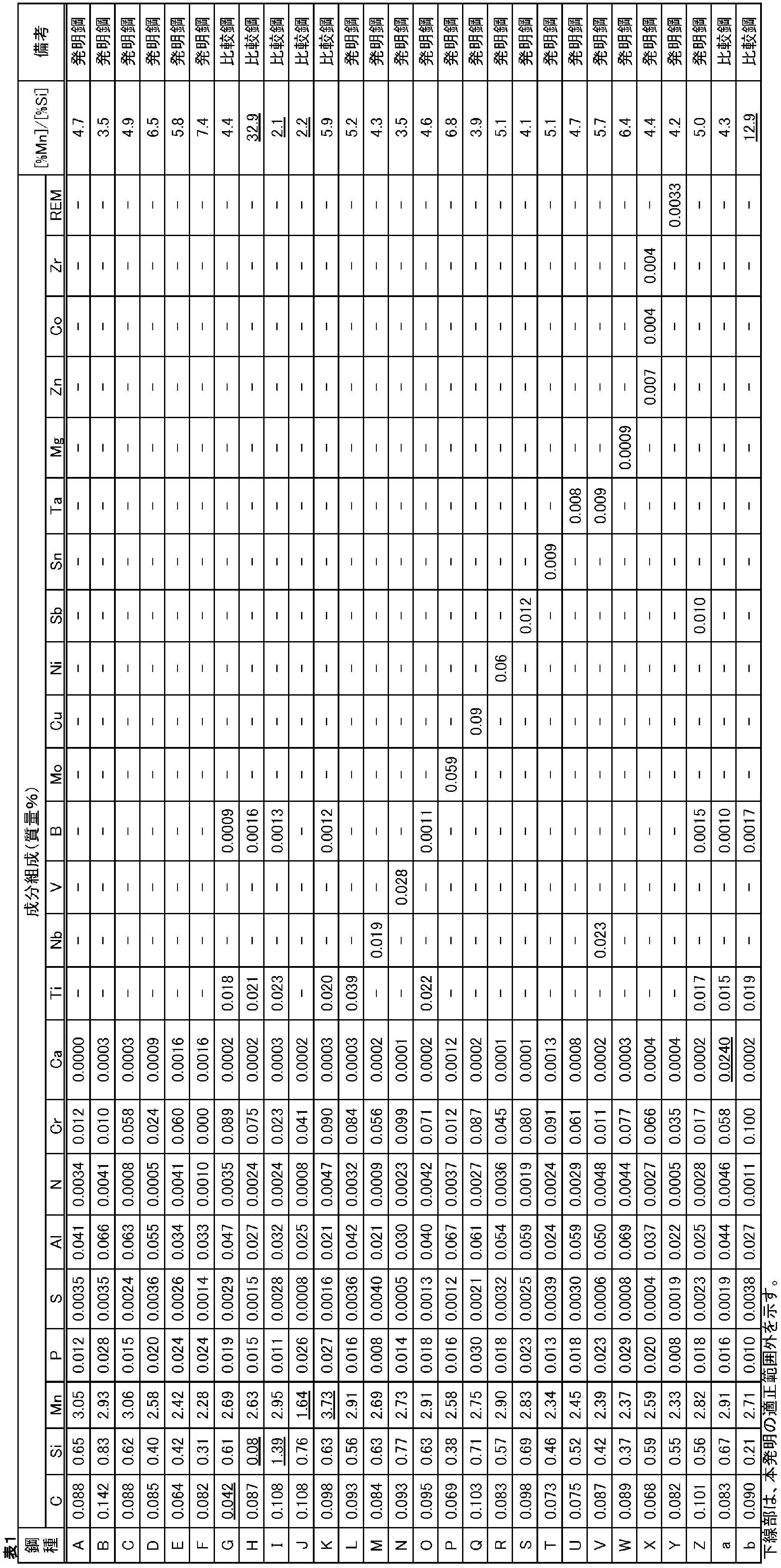
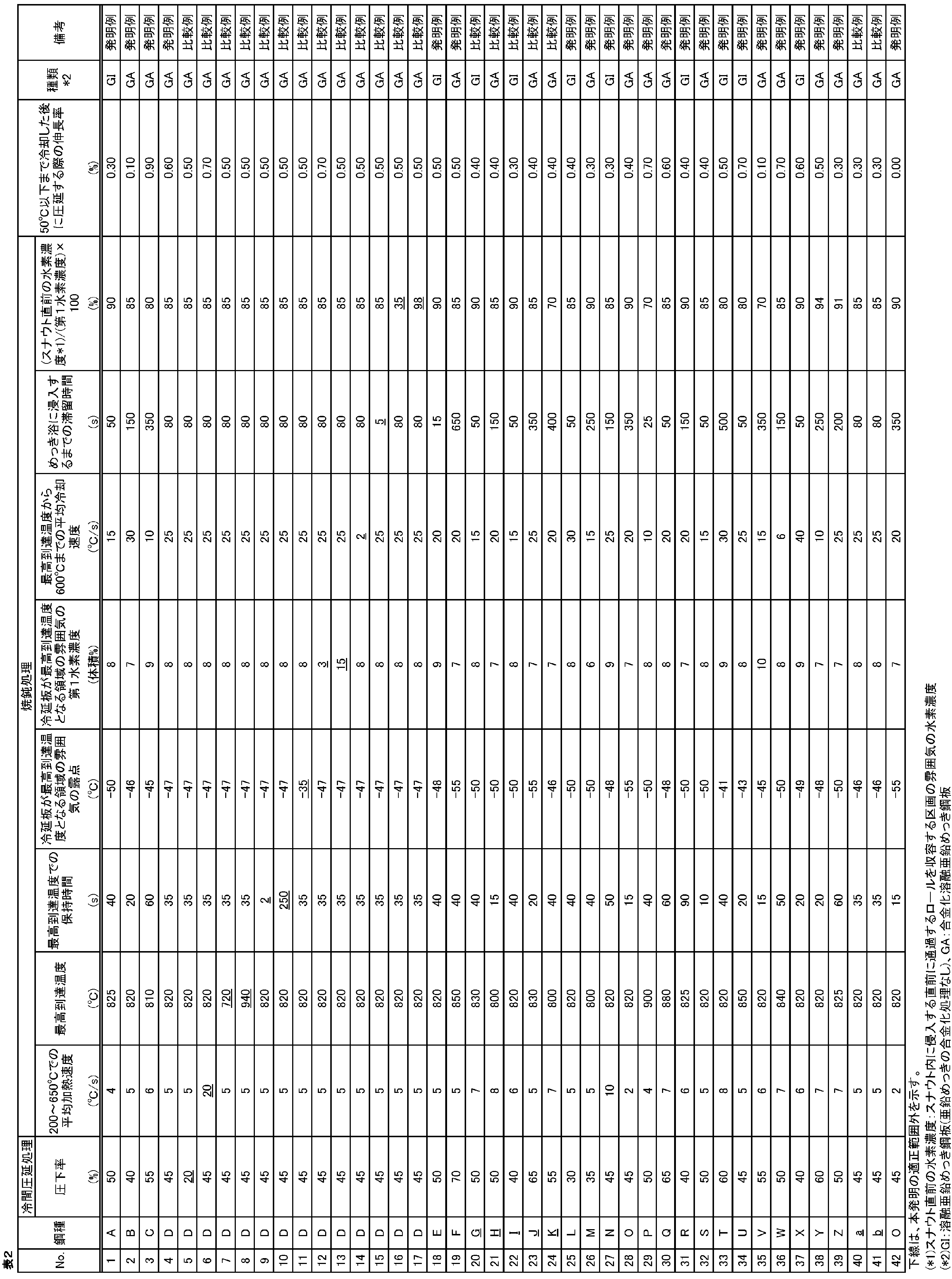
限界穴広げ率:λ(%)={(Df-D0)/D0}×100
ただし、上式において、Dfは亀裂発生時の穴径(mm)、D0は初期穴径(mm)である。鋼板の強度に関係なく、λの値が20%以上の場合に、伸びフランジ性が良好であると判断した。
結果を表3に示す。

2 母材鋼板
3 溶融亜鉛めっき層(または合金化溶融亜鉛めっき層)
Claims (7)
- 母材鋼板と、前記母材鋼板表面に形成された溶融亜鉛めっき層と、を備え、引張強さが780MPa以上である、高強度溶融亜鉛めっき鋼板であって、
前記母材鋼板は、
質量%で、
C:0.050%以上0.200%以下、
Si:0.10%以上0.90%以下、
Mn:2.00%以上3.50%以下、
P:0.001%以上0.100%以下、
S:0.0200%以下、
Al:1.000%以下、
N:0.0100%以下、
Ca:0.0200%以下および
Cr:0.300%以下、
を含有するとともに、[%Mn]/[%Si]が2.9以上11.7以下の関係を満たし、残部がFeおよび不可避的不純物からなる成分組成を有し、
ベイナイトおよびフェライトからなる群から選ばれる1種または2種が面積率の合計で5%以上85%以下、
焼戻しマルテンサイトの面積率が65%以下、
焼入れマルテンサイトの面積率が5%以上40%以下および
残留オーステナイトの体積率が5.0%以下である鋼組織を有し、
前記母材鋼板の表層のMn濃化量に対するSi濃化量の比が0.7以上1.3以下であり、かつ前記母材鋼板中の拡散性水素量が0.80質量ppm以下である、高強度溶融亜鉛めっき鋼板。
ただし、[%Mn]および[%Si]はそれぞれMnおよびSiの鋼中含有量(質量%)を示す。 - 前記溶融亜鉛めっき層はクラックを有する、請求項1に記載の高強度溶融亜鉛めっき鋼板。
- 前記成分組成は、さらに、質量%で、
Ti:0.001%以上0.100%以下、
Nb:0.001%以上0.100%以下、
V:0.001%以上0.100%以下、
B:0.0001%以上0.0100%以下、
Mo:0.005%以上2.000%以下、
Cu:0.01%以上1.00%以下、
Ni:0.01%以上0.50%以下、
Sb:0.001%以上0.200%以下、
Sn:0.001%以上0.200%以下、
Ta:0.001%以上0.100%以下、
Mg:0.0001%以上0.0200%以下、
Zn:0.001%以上0.020%以下、
Co:0.001%以上0.020%以下、
Zr:0.001%以上0.020%以下、および
REM:0.0001%以上0.0200%以下からなる群から選ばれる少なくとも1種を含有する、請求項1または2に記載の高強度溶融亜鉛めっき鋼板。 - 前記溶融亜鉛めっき層が、合金化溶融亜鉛めっき層である、請求項1から3のいずれか1項に記載の高強度溶融亜鉛めっき鋼板。
- 請求項1または3に記載の成分組成を有する鋼スラブに、熱間圧延を施して熱延板とし、
次いで、前記熱延板に酸洗を施し、
次いで、前記熱延板に30%以上の圧下率で冷間圧延を施して冷延板とし、
次いで、前記冷延板を、焼鈍炉と、該焼鈍炉の下流に位置する溶融亜鉛めっき設備とを有し、前記溶融亜鉛めっき設備が、溶融亜鉛めっき浴と、前記焼鈍炉の鋼帯出側に連結し、先端部が前記溶融亜鉛めっき浴に浸漬されたスナウトとを備える、連続溶融亜鉛めっき装置に供給し、
まず、前記焼鈍炉内で、前記冷延板を、200℃以上650℃以下の温度域における平均加熱速度を10℃/s以下として、750℃以上900℃以下の最高到達温度まで加熱し、
次いで、前記焼鈍炉内で前記冷延板が前記最高到達温度となる領域の雰囲気の露点を-40℃以下、当該雰囲気の第1水素濃度を5体積%以上10体積%以下として、前記冷延板を前記最高到達温度にて5s以上100s以下保持し、
次いで、前記冷延板を、平均冷却速度を5℃/s以上として、前記最高到達温度から600℃まで冷却し、
次いで、前記冷延板を、前記溶融亜鉛めっき浴に侵入するまでの滞留時間を15s以上として、前記焼鈍炉内から、前記スナウトを介して前記溶融亜鉛めっき浴に移動させつつ、前記冷延板が前記スナウト内に侵入する直前に通過するロールを収容する区画の雰囲気の水素濃度が、前記第1水素濃度の50%以上95%以下となる条件でさらに冷却し、
次いで、前記冷延板を前記溶融亜鉛めっき浴中に浸漬させて、溶融亜鉛めっき処理を施した後、50℃以下まで冷却する、高強度溶融亜鉛めっき鋼板の製造方法。 - 前記溶融亜鉛めっき処理後に、さらに亜鉛めっき合金化処理を行い、その後、前記50℃以下までの冷却を行う、請求項5に記載の高強度溶融亜鉛めっき鋼板の製造方法。
- 前記50℃以下までの冷却後、前記高強度溶融亜鉛めっき鋼板を0.05%以上1.00%以下の伸長率で圧延する、請求項5または6に記載の高強度溶融亜鉛めっき鋼板の製造方法。
Priority Applications (2)
| Application Number | Priority Date | Filing Date | Title |
|---|---|---|---|
| MX2021009947A MX2021009947A (es) | 2019-02-22 | 2019-11-27 | Lamina de acero galvanizado por inmersion en caliente de alta resistencia y metodo para producir la misma. |
| JP2020518833A JP6777267B1 (ja) | 2019-02-22 | 2019-11-27 | 高強度溶融亜鉛めっき鋼板およびその製造方法 |
Applications Claiming Priority (2)
| Application Number | Priority Date | Filing Date | Title |
|---|---|---|---|
| JP2019-030663 | 2019-02-22 | ||
| JP2019030663 | 2019-02-22 |
Publications (1)
| Publication Number | Publication Date |
|---|---|
| WO2020170542A1 true WO2020170542A1 (ja) | 2020-08-27 |
Family
ID=72143484
Family Applications (1)
| Application Number | Title | Priority Date | Filing Date |
|---|---|---|---|
| PCT/JP2019/046447 Ceased WO2020170542A1 (ja) | 2019-02-22 | 2019-11-27 | 高強度溶融亜鉛めっき鋼板およびその製造方法 |
Country Status (3)
| Country | Link |
|---|---|
| JP (1) | JP6777267B1 (ja) |
| MX (1) | MX2021009947A (ja) |
| WO (1) | WO2020170542A1 (ja) |
Cited By (11)
| Publication number | Priority date | Publication date | Assignee | Title |
|---|---|---|---|---|
| WO2022136684A1 (en) * | 2020-12-23 | 2022-06-30 | Voestalpine Stahl Gmbh | Coiling temperature influenced cold rolled strip or steel |
| WO2022136689A1 (en) * | 2020-12-23 | 2022-06-30 | Voestalpine Stahl Gmbh | A zinc or zinc-alloy coated strip or steel with improved zinc adhesion |
| WO2023181390A1 (ja) * | 2022-03-25 | 2023-09-28 | Jfeスチール株式会社 | 合金化溶融亜鉛めっき鋼板の製造方法 |
| JP7364119B1 (ja) * | 2022-12-01 | 2023-10-18 | Jfeスチール株式会社 | 溶融亜鉛めっき鋼板、溶融亜鉛めっき鋼板を用いてなる部材、部材からなる自動車の骨格構造部品用又は自動車の補強部品、ならびに溶融亜鉛めっき鋼板及び部材の製造方法 |
| CN117043375A (zh) * | 2021-03-24 | 2023-11-10 | 杰富意钢铁株式会社 | 镀锌系钢板和冷轧钢板 |
| CN117062928A (zh) * | 2021-03-23 | 2023-11-14 | 杰富意钢铁株式会社 | 镀锌钢板、部件以及它们的制造方法 |
| JPWO2023218731A1 (ja) * | 2022-05-11 | 2023-11-16 | ||
| JPWO2023218730A1 (ja) * | 2022-05-11 | 2023-11-16 | ||
| JP2024500703A (ja) * | 2020-12-18 | 2024-01-10 | ポスコ カンパニー リミテッド | 表面品質と電気抵抗スポット溶接性に優れた高強度溶融亜鉛めっき鋼板及びその製造方法 |
| WO2024209641A1 (ja) | 2023-04-06 | 2024-10-10 | Jfeスチール株式会社 | 溶融亜鉛めっき鋼板、溶融亜鉛めっき鋼板を用いてなる部材、部材からなる自動車の骨格構造部品又は自動車の補強部品、ならびに溶融亜鉛めっき鋼板及び部材の製造方法 |
| KR20250149763A (ko) | 2023-03-28 | 2025-10-16 | 제이에프이 스틸 가부시키가이샤 | 고강도 용융 아연 도금 강판의 제조 방법 |
Families Citing this family (2)
| Publication number | Priority date | Publication date | Assignee | Title |
|---|---|---|---|---|
| JP7195501B1 (ja) | 2021-06-24 | 2022-12-26 | Jfeスチール株式会社 | 溶融亜鉛めっき鋼板およびその製造方法、ならびに、部材 |
| KR20260003180A (ko) | 2023-06-09 | 2026-01-06 | 제이에프이 스틸 가부시키가이샤 | 용융 아연 도금 강판 및 그 제조 방법, 그리고 부재와 그 제조 방법, 및 당해 부재로 이루어지는 자동차의 골격 구조 부품 또는 자동차의 보강 부품 |
Citations (5)
| Publication number | Priority date | Publication date | Assignee | Title |
|---|---|---|---|---|
| JP2010255113A (ja) * | 2009-03-31 | 2010-11-11 | Jfe Steel Corp | 高強度溶融亜鉛めっき鋼板およびその製造方法 |
| WO2015029404A1 (ja) * | 2013-08-26 | 2015-03-05 | Jfeスチール株式会社 | 高強度溶融亜鉛めっき鋼板及びその製造方法 |
| WO2017131056A1 (ja) * | 2016-01-27 | 2017-08-03 | Jfeスチール株式会社 | 高降伏比型高強度亜鉛めっき鋼板及びその製造方法 |
| WO2018124157A1 (ja) * | 2016-12-27 | 2018-07-05 | Jfeスチール株式会社 | 高強度亜鉛めっき鋼板及びその製造方法 |
| WO2019189849A1 (ja) * | 2018-03-30 | 2019-10-03 | Jfeスチール株式会社 | 高強度亜鉛めっき鋼板、高強度部材およびそれらの製造方法 |
-
2019
- 2019-11-27 WO PCT/JP2019/046447 patent/WO2020170542A1/ja not_active Ceased
- 2019-11-27 MX MX2021009947A patent/MX2021009947A/es unknown
- 2019-11-27 JP JP2020518833A patent/JP6777267B1/ja active Active
Patent Citations (5)
| Publication number | Priority date | Publication date | Assignee | Title |
|---|---|---|---|---|
| JP2010255113A (ja) * | 2009-03-31 | 2010-11-11 | Jfe Steel Corp | 高強度溶融亜鉛めっき鋼板およびその製造方法 |
| WO2015029404A1 (ja) * | 2013-08-26 | 2015-03-05 | Jfeスチール株式会社 | 高強度溶融亜鉛めっき鋼板及びその製造方法 |
| WO2017131056A1 (ja) * | 2016-01-27 | 2017-08-03 | Jfeスチール株式会社 | 高降伏比型高強度亜鉛めっき鋼板及びその製造方法 |
| WO2018124157A1 (ja) * | 2016-12-27 | 2018-07-05 | Jfeスチール株式会社 | 高強度亜鉛めっき鋼板及びその製造方法 |
| WO2019189849A1 (ja) * | 2018-03-30 | 2019-10-03 | Jfeスチール株式会社 | 高強度亜鉛めっき鋼板、高強度部材およびそれらの製造方法 |
Cited By (25)
| Publication number | Priority date | Publication date | Assignee | Title |
|---|---|---|---|---|
| JP7832210B2 (ja) | 2020-12-18 | 2026-03-17 | ポスコ カンパニー リミテッド | 表面品質と電気抵抗スポット溶接性に優れた高強度溶融亜鉛めっき鋼板及びその製造方法 |
| US12371770B2 (en) | 2020-12-18 | 2025-07-29 | Posco Co., Ltd | High-strength hot-dip galvanized steel sheet having excellent surface quality and electric resistance spot weldability, and manufacturing method therefor |
| JP2024500703A (ja) * | 2020-12-18 | 2024-01-10 | ポスコ カンパニー リミテッド | 表面品質と電気抵抗スポット溶接性に優れた高強度溶融亜鉛めっき鋼板及びその製造方法 |
| WO2022136684A1 (en) * | 2020-12-23 | 2022-06-30 | Voestalpine Stahl Gmbh | Coiling temperature influenced cold rolled strip or steel |
| WO2022136689A1 (en) * | 2020-12-23 | 2022-06-30 | Voestalpine Stahl Gmbh | A zinc or zinc-alloy coated strip or steel with improved zinc adhesion |
| CN117062928A (zh) * | 2021-03-23 | 2023-11-14 | 杰富意钢铁株式会社 | 镀锌钢板、部件以及它们的制造方法 |
| CN117043375A (zh) * | 2021-03-24 | 2023-11-10 | 杰富意钢铁株式会社 | 镀锌系钢板和冷轧钢板 |
| WO2023181390A1 (ja) * | 2022-03-25 | 2023-09-28 | Jfeスチール株式会社 | 合金化溶融亜鉛めっき鋼板の製造方法 |
| JP7480928B2 (ja) | 2022-03-25 | 2024-05-10 | Jfeスチール株式会社 | 合金化溶融亜鉛めっき鋼板の製造方法 |
| JPWO2023181390A1 (ja) * | 2022-03-25 | 2023-09-28 | ||
| JP7601257B2 (ja) | 2022-05-11 | 2024-12-17 | Jfeスチール株式会社 | 鋼板、部材およびそれらの製造方法 |
| JPWO2023218731A1 (ja) * | 2022-05-11 | 2023-11-16 | ||
| JPWO2023218730A1 (ja) * | 2022-05-11 | 2023-11-16 | ||
| WO2023218576A1 (ja) * | 2022-05-11 | 2023-11-16 | Jfeスチール株式会社 | 亜鉛めっき鋼板、部材およびそれらの製造方法 |
| WO2023218730A1 (ja) * | 2022-05-11 | 2023-11-16 | Jfeスチール株式会社 | 鋼板、部材およびそれらの製造方法 |
| WO2023218731A1 (ja) * | 2022-05-11 | 2023-11-16 | Jfeスチール株式会社 | 鋼板、部材およびそれらの製造方法 |
| JP7601256B2 (ja) | 2022-05-11 | 2024-12-17 | Jfeスチール株式会社 | 鋼板、部材およびそれらの製造方法 |
| WO2024116396A1 (ja) * | 2022-12-01 | 2024-06-06 | Jfeスチール株式会社 | 溶融亜鉛めっき鋼板、溶融亜鉛めっき鋼板を用いてなる部材、部材からなる自動車の骨格構造部品用又は自動車の補強部品、ならびに溶融亜鉛めっき鋼板及び部材の製造方法 |
| KR20250075717A (ko) | 2022-12-01 | 2025-05-28 | 제이에프이 스틸 가부시키가이샤 | 용융 아연 도금 강판, 용융 아연 도금 강판을 사용하여 이루어지는 부재, 부재로 이루어지는 자동차의 골격 구조 부품용 또는 자동차의 보강 부품, 그리고 용융 아연 도금 강판 및 부재의 제조 방법 |
| EP4600382A4 (en) * | 2022-12-01 | 2025-12-03 | Jfe Steel Corp | HOT-DIP GALVANIZED STEEL SHEET, an element made using this sheet, an automotive reinforcement component or an automotive body structure component made of said element, and methods of manufacturing said hot-dip galvanized steel sheet and said element |
| JP7364119B1 (ja) * | 2022-12-01 | 2023-10-18 | Jfeスチール株式会社 | 溶融亜鉛めっき鋼板、溶融亜鉛めっき鋼板を用いてなる部材、部材からなる自動車の骨格構造部品用又は自動車の補強部品、ならびに溶融亜鉛めっき鋼板及び部材の製造方法 |
| KR20250149763A (ko) | 2023-03-28 | 2025-10-16 | 제이에프이 스틸 가부시키가이샤 | 고강도 용융 아연 도금 강판의 제조 방법 |
| EP4656764A1 (en) | 2023-03-28 | 2025-12-03 | JFE Steel Corporation | Method for manufacturing high-strength, hot-dip galvanized steel sheet |
| WO2024209641A1 (ja) | 2023-04-06 | 2024-10-10 | Jfeスチール株式会社 | 溶融亜鉛めっき鋼板、溶融亜鉛めっき鋼板を用いてなる部材、部材からなる自動車の骨格構造部品又は自動車の補強部品、ならびに溶融亜鉛めっき鋼板及び部材の製造方法 |
| EP4647519A1 (en) | 2023-04-06 | 2025-11-12 | JFE Steel Corporation | Hot-dip galvanized steel sheet, member formed using hot-dip galvanized steel sheet, automobile frame structural component or automobile reinforcement component comprising member, and method for producing hot-dip galvanized steel sheet and member |
Also Published As
| Publication number | Publication date |
|---|---|
| MX2021009947A (es) | 2021-09-21 |
| JPWO2020170542A1 (ja) | 2021-03-11 |
| JP6777267B1 (ja) | 2020-10-28 |
Similar Documents
| Publication | Publication Date | Title |
|---|---|---|
| JP6777267B1 (ja) | 高強度溶融亜鉛めっき鋼板およびその製造方法 | |
| US12435384B2 (en) | High-strength steel sheet and method for manufacturing same | |
| CN113544302B (zh) | 高强度钢板及其制造方法 | |
| EP3309273B1 (en) | Galvannealed steel sheet and method for manufacturing same | |
| CN106574342B (zh) | 高强度钢板及其制造方法、以及高强度镀锌钢板的制造方法 | |
| JP5967319B2 (ja) | 高強度鋼板およびその製造方法 | |
| CN106574340B (zh) | 高强度钢板及其制造方法、以及高强度镀锌钢板的制造方法 | |
| CN107075627B (zh) | 高强度钢板及其制造方法、以及高强度镀锌钢板的制造方法 | |
| JP5967320B2 (ja) | 高強度鋼板およびその製造方法 | |
| CN106574341B (zh) | 高强度钢板及其制造方法、以及高强度镀锌钢板的制造方法 | |
| JP6747612B1 (ja) | 高強度鋼板およびその製造方法 | |
| CN110312813A (zh) | 高强度钢板及其制造方法 | |
| CN110291217A (zh) | 高强度钢板及其制造方法 | |
| WO2018043473A1 (ja) | 高強度鋼板およびその製造方法 | |
| JP7195501B1 (ja) | 溶融亜鉛めっき鋼板およびその製造方法、ならびに、部材 | |
| CN114555845B (zh) | 高强度钢板及其制造方法 | |
| JP2013133499A (ja) | 曲げ加工性に優れた高張力熱延鋼板およびその製造方法 | |
| WO2022138894A1 (ja) | 鋼板、部材およびそれらの製造方法 | |
| EP4696800A1 (en) | High strength steel sheet, high strength plated steel sheet, methods for producing same, and member | |
| CN116806274B (zh) | 高强度钢板及其制造方法 | |
| CN110214196A (zh) | 钢板及镀覆钢板 | |
| JP7298647B2 (ja) | 高強度鋼板およびその製造方法 | |
| JP7779449B1 (ja) | 亜鉛めっき鋼板および部材、ならびに、それらの製造方法 | |
| CN116829752B (zh) | 高强度钢板及其制造方法 | |
| JP2018119207A (ja) | バーリング性に優れる溶融Zn−Al−Mg系めっき鋼板および製造方法 |
Legal Events
| Date | Code | Title | Description |
|---|---|---|---|
| ENP | Entry into the national phase |
Ref document number: 2020518833 Country of ref document: JP Kind code of ref document: A |
|
| 121 | Ep: the epo has been informed by wipo that ep was designated in this application |
Ref document number: 19916471 Country of ref document: EP Kind code of ref document: A1 |
|
| WWE | Wipo information: entry into national phase |
Ref document number: MX/A/2021/009947 Country of ref document: MX |
|
| NENP | Non-entry into the national phase |
Ref country code: DE |
|
| WWP | Wipo information: published in national office |
Ref document number: MX/A/2021/009947 Country of ref document: MX |
|
| 122 | Ep: pct application non-entry in european phase |
Ref document number: 19916471 Country of ref document: EP Kind code of ref document: A1 |
|
| WWG | Wipo information: grant in national office |
Ref document number: MX/A/2021/009947 Country of ref document: MX |