WO2020166485A1 - 伝送装置、時刻伝送システム、および、遅延補正方法 - Google Patents
伝送装置、時刻伝送システム、および、遅延補正方法 Download PDFInfo
- Publication number
- WO2020166485A1 WO2020166485A1 PCT/JP2020/004618 JP2020004618W WO2020166485A1 WO 2020166485 A1 WO2020166485 A1 WO 2020166485A1 JP 2020004618 W JP2020004618 W JP 2020004618W WO 2020166485 A1 WO2020166485 A1 WO 2020166485A1
- Authority
- WO
- WIPO (PCT)
- Prior art keywords
- delay
- transmission device
- time
- time synchronization
- transmission
- Prior art date
- Legal status (The legal status is an assumption and is not a legal conclusion. Google has not performed a legal analysis and makes no representation as to the accuracy of the status listed.)
- Ceased
Links
Images








Classifications
-
- H—ELECTRICITY
- H04—ELECTRIC COMMUNICATION TECHNIQUE
- H04J—MULTIPLEX COMMUNICATION
- H04J3/00—Time-division multiplex systems
- H04J3/02—Details
- H04J3/06—Synchronising arrangements
- H04J3/0635—Clock or time synchronisation in a network
- H04J3/0682—Clock or time synchronisation in a network by delay compensation, e.g. by compensation of propagation delay or variations thereof, by ranging
-
- H—ELECTRICITY
- H04—ELECTRIC COMMUNICATION TECHNIQUE
- H04J—MULTIPLEX COMMUNICATION
- H04J3/00—Time-division multiplex systems
- H04J3/02—Details
- H04J3/06—Synchronising arrangements
- H04J3/0635—Clock or time synchronisation in a network
- H04J3/0638—Clock or time synchronisation among nodes; Internode synchronisation
- H04J3/0658—Clock or time synchronisation among packet nodes
- H04J3/0661—Clock or time synchronisation among packet nodes using timestamps
- H04J3/0667—Bidirectional timestamps, e.g. NTP or PTP for compensation of clock drift and for compensation of propagation delays
-
- G—PHYSICS
- G04—HOROLOGY
- G04G—ELECTRONIC TIME-PIECES
- G04G5/00—Setting, i.e. correcting or changing, the time-indication
-
- H—ELECTRICITY
- H04—ELECTRIC COMMUNICATION TECHNIQUE
- H04J—MULTIPLEX COMMUNICATION
- H04J3/00—Time-division multiplex systems
- H04J3/02—Details
- H04J3/06—Synchronising arrangements
- H04J3/0635—Clock or time synchronisation in a network
- H04J3/0638—Clock or time synchronisation among nodes; Internode synchronisation
- H04J3/0658—Clock or time synchronisation among packet nodes
- H04J3/0673—Clock or time synchronisation among packet nodes using intermediate nodes, e.g. modification of a received timestamp before further transmission to the next packet node, e.g. including internal delay time or residence time into the packet
-
- H—ELECTRICITY
- H04—ELECTRIC COMMUNICATION TECHNIQUE
- H04J—MULTIPLEX COMMUNICATION
- H04J3/00—Time-division multiplex systems
- H04J3/02—Details
- H04J3/14—Monitoring arrangements
Definitions
- the present invention relates to a transmission device, a time transmission system, and a delay correction method.
- Time synchronization technology will be required in the future in the next generation mobile communication 5G (Generation) and the like in the cooperation between base stations in mobile.
- the time synchronization system is realized, for example, by a configuration in which a GM (Grand Master), which is a time reference device, is distributed and arranged at each point.
- the GM at each point functions as a GNSS receiver that directly receives signals from the GNSS (Global Navigation Satellite System) satellite, and delivers the received signals directly to the end application.
- GNSS Global Navigation Satellite System
- the cost will increase accordingly.
- the accuracy of time deteriorates in the time zone when the signal from the satellite cannot be received due to bad weather.
- PTP Precision Time Protocol
- GM aggregated GNSS receiver
- the GM can transmit the time information economically and with high accuracy by superimposing the PTP packet on the main signal.
- FIG. 17 is a configuration diagram of a time transmission system to which the time synchronization technology is applied.
- the time transmission system is configured by connecting a GM node 82z, which is a PTP node corresponding to PTP, BC (Boundary Clock) nodes 83z and 84z, and an OC (Ordinary Clock) node 85z via a network.
- GM node 82z which is a PTP node corresponding to PTP
- BC (Boundary Clock) nodes 83z and 84z BC (Boundary Clock) nodes 83z and 84z
- an OC Organic Clock
- the arrow base side of the thick arrow is the up side
- the arrow head side of the thick arrow is the down side. That is, accurate time information is propagated downward in the order of GM node 82z ⁇ BC node 83z ⁇ BC node 84z ⁇ OC node 85z.
- the GM node 82z includes an antenna 82a that directly receives signals from GPS satellites 81z.
- the BC node 83z is a slave node 92z that receives time information from the GM node 82z that is the master node 91z, and thereafter functions as a master node 91z that provides time information to the BC node 84z.
- the BC node 84z is a slave node 92z that receives time information from the BC node 83z, and thereafter functions as a master node 91z that provides time information to the OC node 85z.
- the OC node 85z is a slave node 92z that receives the time information from the BC node 84z, and then provides the end terminal 86z with the time information.
- the difference between the BC nodes 83z and 84z and the OC node 85z is that there are multiple connection ports to other PTP nodes on the BC nodes 83z and 84z, and only one on the
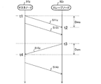
- FIG. 18 is a sequence diagram showing the mechanism of PTP.
- the PTP packet to which the time information (time stamp) is added is transmitted and received between the master node 91z and the slave node 92z.
- a downlink Sync message (S11z), a downlink Follow-up message (S12z), an uplink Delay_Request message (S13z), and a downlink Delay_Response message (S14z) are transmitted and received in order.
- the originating time t1 is the time when the Sync message (S11z) is transmitted from the master node 91z.
- the arrival time t2 is the time when the Sync message arrives at the slave node 92z.
- the originating time t3 is the time when the Delay_Request message is transmitted from the slave node 92z.
- the arrival time t4 is the time when the Delay_Request message arrives at the master node 91z.
- the arrival time t4 is included in the Delay_Response message for the Delay_Request message and is notified to the slave node 92z.
- the slave node 92z can grasp all four time stamps (departure time t1 to arrival time t4).
- the intra-device delay in the middle of the transmission path is, for example, a delay that may vary due to buffering due to packet processing or frame processing.
- the delay of the transmission line may vary due to the delay of the fiber length difference in the two-core two-way communication such as a delay of 5 ns due to the difference of the optical path length of 1 m (5 ns/m) and the temperature change of the transmission line. There is a delay.
- the time error between geographically distant bases increases in proportion to the difference in optical path length of the intra-station wiring.
- the main object of the present invention is to provide a time synchronization mechanism that reduces the influence of the link asymmetry between the time synchronization devices.
- the transmission device of the present invention has the following features.
- the first transmission device connected to the first time synchronization device side and the second transmission device facing the first transmission device and connected to the second time synchronization device side are connected to the first transmission device.
- a transmission device used in a time transmission system that transmits and receives a time synchronization packet between the time synchronization device and the second time synchronization device, and synchronizes the time of the second time synchronization device based on the time information of the transmission and reception.
- a transmission unit that simultaneously transmits delay calculation packets for a plurality of wavelengths to the opposite transmission device, A first propagation delay from the opposite transmission device to the own device is obtained based on the difference in arrival times of the delay calculation packets for a plurality of wavelengths received from the opposite transmission device, and the opposite transmission device is obtained.
- the receiving unit receives a notification of the second propagation delay from the own device to the opposite transmission device obtained by, and a receiving unit for obtaining a setting delay larger than the first propagation delay and the second propagation delay, The receiving unit, When the time synchronization packets for a plurality of wavelengths are received from the opposite transmission device, the third propagation from the opposite transmission device to the own device is performed based on the difference in the arrival times of the time synchronization packets. Ask for delay, With respect to the received time synchronization packet, a waiting delay from the third propagation delay to the set delay is generated and then transmitted to the time synchronization device connected to the own device side.
- the present invention provides a time transmission system configured to include the transmission device, the first time synchronization device, and the second time synchronization device,
- the second time synchronizer calculates an offset value, which is a clock shift of the second time synchronizer, by using an originating time and an arrival time of the time synchronizing packet between the time synchronizers. ..
- time synchronization can be realized based on the time of arrival and the time of arrival of the time synchronization packet that is not affected by the link asymmetry between the time synchronization devices.
- FIG. 1 is a configuration diagram of a time transmission system to which the time synchronization technology is applied.
- PTP packets time synchronization packets
- the master node first time synchronization device
- the slave node second time synchronization device
- the first transmission device 1 and the second transmission device 2 are provided so as to face each other.
- the directly connected master node 3 and the first transmission device 1 form a set
- the directly connected slave node 4 and the second transmission device 2 form a set.
- these transmission devices have a queuing function (details are shown in FIG. 3) that reduces the influence of link asymmetry between the master node 3 and the slave node 4.
- the time transmission system transmits a downlink Sync message (S11z in FIG. 18) through a route of master node 3 ⁇ first transmission device 1 ⁇ second transmission device 2 ⁇ slave node 4, and an uplink Delay_Request message through the reverse route. (S13z in FIG. 18) is transmitted.
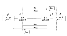
- the propagation delay generated between the first transmission device 1 and the second transmission device 2, which is the main component of the propagation delay from the master node 3 to the slave node 4, is hereinafter referred to as “Dms” (first propagation delay).
- the propagation delay that occurs between the second transmission device 2 and the first transmission device 1, which is the main component of the propagation delay of the slave node 4 ⁇ the master node 3, is hereinafter referred to as “Dsm” (second propagation delay). Note that “ms” of the propagation delay Dms indicates the direction of master ⁇ slave, and “sm” of the propagation delay Dsm indicates the direction of slave ⁇ master.
- the asymmetry between the transmission devices and the asymmetry between the time synchronization devices become substantially equal.
- a configuration in which the wiring between the master node 3 and the first transmission device 1 and the wiring between the second transmission device 2 and the slave node 4 are up-down and equal-length wiring.
- FIG. 2 is an explanatory diagram showing a delay calculation method in the transmission device (first transmission device 1, second transmission device 2).
- Each of the propagation delay Dms and the propagation delay Dsm is measured as a delay amount.
- Propagation delay Dmax (setting delay) is obtained by adding a certain amount of margin to the maximum value of delay amount. That is, the propagation delay Dmax is set to a value larger than any of the propagation delays Dms and Dsm.
- Each transmission device waits for a PTP packet received by itself and waits for a shortage from the propagation delay (third propagation delay) required from the source of the PTP packet to itself to the propagation delay Dmax.
- FIG. 3 is a configuration diagram when link symmetry is subsequently established for the time transmission system of FIG.
- the second transmission device 2 causes the PTP packet arriving with the propagation delay Dms to wait for the waiting delay Wms, so that the total delay of the transmission path becomes the propagation delay Dmax. ..
- the first transmission device 1 also causes the PTP packet arriving with the propagation delay Dsm to wait for the waiting delay Wsm, so that the total delay of the transmission path becomes the propagation delay Dmax. ..
- the uplink and downlink delays are equalized, and link symmetry is subsequently established.
- the delay may vary even in communication in the same direction depending on the congestion status of the network at the transmission timing.
- this delay variation also causes all packets to have the same delay by waiting in each transmission device for the shortage of the propagation delay Dmax.
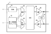
- FIG. 4 is a configuration diagram of the first transmission device 1.
- the first transmission device 1 is configured as a device to which a WDM (Wavelength Division Multiplexing) technique for relaying an optical signal is applied.
- the first transmission device 1 has a TRPN (Transponder) 91, a MUX (multiplexer) 92, a DEMUX (demultiplexer) 93, an OXC (Optical Cross Connect) 94, and an AMP (Amplifier) 95 as a basic packet transmission unit.
- 96 and an OSC (Optical Supervisory Channel) 97 are basically components that do not need to be replaced after they have been introduced into the first transmission device 1. As an exception, replacement or additional deployment is required when communication demand increases rapidly or parts fail.
- the first transmission device 1 has a first synchronization module 10 as a processing unit that handles a time synchronization process using a unique packet for measuring the propagation delays Dms and Dsm in addition to the PTP packet.
- the first synchronization module 10 transmits/receives PTP packets to/from the master node 3 of the connection destination. That is, the first transmission device 1 can add the first synchronization module 10 to the device as an independent separate component without modifying the basic packet transmission unit. As a result, the function of establishing the link symmetry described in FIGS. 1 to 3 can be added at low cost.
- the TRPN 91 connects to general routers and transfer devices other than the master node 3 to send and receive packets.
- the optical signal transmitted from the first synchronization module 10 and the TRPN 91 is output to the optical network via the MUX 92, OXC94, AMP95, OSC97.
- the OSC 97 monitors the transmission path and controls the device.
- the optical signal received from the optical network is notified to the first synchronization module 10 and the TRPN 91 via the OSC 97, AMP 96, OXC 94, MUX 92, and DEMUX 93.
- FIG. 5 is a configuration diagram of the second transmission device 2.
- the second transmission device 2 also has a TRPN 91, a MUX 92, a DEMUX 93, an OXC 94, AMPs 95 and 96, and an OSC 97 as a basic packet transmission unit. Since the basic function of the packet transmission unit is the same in both the first transmission device 1 and the second transmission device 2, the description thereof will be omitted in FIG. Then, the second transmission device 2 has the second synchronization module 20 as a processing unit that handles the time synchronization processing using the PTP packet and the unique packet. The second synchronization module 20 transmits/receives a PTP packet to/from the slave node 4 of the connection destination.
- FIG. 6 is a configuration diagram of the first synchronization module 10 and the second synchronization module 20. Both of these modules have a common configuration.
- the control unit which is a part of the components of both modules, includes a CPU (Central Processing Unit), a memory, a storage unit (storage unit) exemplified by a hard disk, a non-volatile memory, an SSD (solid state drive), and the like. It may be configured as a computer having a network interface. In the computer of the control unit, the CPU causes each processing unit to operate by executing a program (also referred to as an application or its abbreviation application) read in the memory.
- a program also referred to as an application or its abbreviation application
- the O/E/E/O unit 11, the variable wavelength transmitter 164, the coupler 171, and the optical receiving unit 175 are configured as individual hardware (hardware).
- the PHY unit 12 and the MAC unit 13 are configured as an LSI (Large Scale Integration).
- the first synchronization module 10 and the second synchronization module 20 respectively include a transmission unit 16 that transmits a PTP packet and an original packet, a reception unit 17 that receives a PTP packet and an original packet, and another common unit 19.
- the common unit 19 includes an O/E/E/O (Optical/Electronic/Electronic/Optical signal converter) unit 11, a PHY (physical layer) unit 12, a MAC (Medium Access Control) unit 13, and a clock. It has a timer 14 and an environment information management unit 15.
- the clock timer 14 supplies a frequency/timing in order to ensure a synchronous operation between arbitrary functional units in the first synchronization module 10.
- the environment information management unit 15 manages information on the wavelength dispersion coefficient and the temperature.
- the transmission unit 16 is provided with a queue unit 162, a trigger assignment unit 163, and a variable wavelength transmitter 164 for two wavelengths (two wavelengths), and a copy unit for copying and inputting the same packet for each system. 161, 165 are also provided.
- the copy unit 161 copies the PTP packet into two wavelengths.
- the queue unit 162 stores PTP packets and unique packets to be transmitted.
- the trigger adding unit 163 adds a trigger for detecting the arrival time difference of the time difference detecting unit 172 to the PTP packet and the unique packet to be transmitted.
- the trigger is implemented as a specific signal pattern (such as “101010...11”) that allows the timing of a measurement target to be recognized, such as an Ethernet (registered trademark) preamble.
- the trigger may be embedded as a specific value of a specific field in the packet.
- the variable wavelength transmitter 164 for each of the two wavelengths converts the PTP packet and unique packet to be transmitted into an optical signal having a different wavelength from the other variable wavelength transmitter 164. Then, the variable wavelength transmitters 164 for each of the two wavelengths transmit the converted optical signal at the same time as the other variable wavelength transmitter 164. Although two wavelengths are illustrated, three or more variable wavelength transmitters 164 may simultaneously transmit optical signals of three or more wavelengths.
- the copy unit 165 copies the unique packet to two wavelengths.
- the reception unit 17 includes a coupler 171, a time difference detection unit 172, a delay calculation unit 173, a delay management unit 174, an optical reception unit 175, an identification selector 176, a delay amount control unit 177, and a variable delay unit 178.
- the coupler 171 receives the optical signals of two or more wavelengths transmitted from the variable wavelength transmitter 164, and outputs them to the time difference detection unit 172 and the optical reception unit 175.
- the time difference detection unit 172 detects the arrival time difference ⁇ t of optical signals of two or more wavelengths (details are shown in FIG. 7).
- the time difference detection unit 172 can be realized by using a function group included in the oscilloscope, for example.
- the delay calculation unit 173 calculates the propagation delays Dms and Dsm from the arrival time difference ⁇ t (details are shown in FIG. 7).
- the delay management unit 174 exchanges the calculated propagation delays Dms and Dsm between the first synchronization module 10 and the second synchronization module 20, and determines the waiting delays Wms and Wsm. , Adjust so that the delay in the transmission section is the propagation delay Dmax (with the same value and symmetry).
- the optical receiver 175 converts the optical signal from the coupler 171 into an electric signal. Processing such as dispersion compensation may be performed during this conversion.
- the identification selector 176 selects and outputs one of the packets (electrical signals) for two wavelengths (for example, a packet that arrives early). As the output destination, the identification selector 176 outputs the PTP packet to the variable delay unit 178 and the unique packet to the copy unit 165.
- the delay amount control unit 177 sets the waiting delays Wms and Wsm determined by the delay management unit 174 in the variable delay unit 178.
- the variable delay unit 178 waits for the PTP packet by the set waiting delays Wms and Wsm.
- FIG. 7 is an explanatory diagram showing a process of measuring the propagation delay between the synchronization modules.
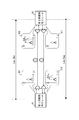
- the distance of the downlink transmission line from the first synchronization module 10 to the second synchronization module 20 is Lms
- the distance of the upstream transmission line from the second synchronization module 20 to the first synchronization module 10 is Lsm. ..
- the chromatic dispersion coefficient C [ps/nm/km] of the fiber is known, and Lms and Lsm are unknown.
- the fiber pair between each synchronization module and the time synchronization device master node 3, slave node 4) has the same length. Further, the fiber group between the synchronization module and the MUX92/DEMUX93 shown in FIGS.
- the variable wavelength transmitter 164 of the first synchronization module 10 simultaneously inputs optical signals of two wavelengths (wavelength difference: ⁇ [nm]) to the transmission path (reference numeral 301).
- the wavelengths of the thick line optical signal and the thin line optical signal are different.
- the time difference detection unit 172 of the second synchronization module 20 detects the arrival time difference ( ⁇ t12 [ps]) of the optical signals of two or more wavelengths (reference numeral 302).
- the first synchronization module 10 causes the arrival time difference ( ⁇ t21 [ps]) is detected (reference numeral 312), and the propagation delay Dsm is calculated.
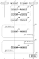
- FIG. 8 is a sequence diagram showing the entire process of time synchronization. This sequence diagram is roughly classified into three processing blocks.
- (3) Processing of notifying the master node 3 as the propagation delay Dmax by waiting for the upstream PTP packet by the waiting delay Wsm (S20 details S21 to S24).
- the propagation delay Dmax is set with a margin with respect to the actual measured propagation delays Dms, Dsm, and other delay amounts. Therefore, although the measured values of the propagation delays Dms and Dsm change every moment depending on the congestion situation of the network, the preparation process (S30) of (1) basically needs to be measured once. On the other hand, when a large amount of network equipment update such as network expansion occurs, the amount of delay also greatly changes, so it is preferable to execute the preparation process (S30) again.
- the first transmission device 1 transmits the unique packet for obtaining the propagation delay Dms to the second transmission device 2 by performing the processing on the transmission side described later in FIG.
- the second transmission device 2 obtains the propagation delay Dms by performing the processing on the receiving side described later in FIG.
- the second transmission device 2 transmits the unique packet for obtaining the propagation delay Dsm to the first transmission device 1 by performing the processing on the transmission side described later in FIG.
- the first transmission device 1 obtains the propagation delay Dsm by performing the processing on the receiving side described later in FIG.
- the unique packet in S33 also includes the propagation delay Dms obtained in S32.
- the first synchronization module 10 can acquire the notified propagation delay Dms in addition to the propagation delay Dsm obtained by itself.
- the first transmission device 1 obtains the propagation delay Dmax from the propagation delays Dms and Dsm by performing the processing on the transmission side described later in FIG. As a result, the waiting delay Wsm can be set in the variable delay unit 178 of itself. Then, the first transmission device 1 transmits a unique packet including the determined propagation delay Dmax to the second transmission device 2. As S36, the second transmission device 2 performs the processing on the receiving side described later in FIG. 14 to obtain the waiting delay Wms from the notified propagation delay Dmax, and sets the waiting delay Wms in its own variable delay unit 178. it can.
- the downlink PTP packet is a downlink Sync message (S11z in FIG. 18) that is a target for measuring the arrival and departure times.
- the downlink Follow-up message (S12z) and the downlink Delay_Response message (S14z) which are not the measurement targets of the arrival and departure times, may be the target of the notification process (S10) (waiting), or are not the target. May be used (conventional PTP processing is performed without waiting).
- the master node 3 transmits the downlink PTP packet to the slave node 4, and the first transmission device 1 as the relay destination receives the PTP packet.
- the first transmission device 1 performs the transmitting side processing described later in FIG. 15 and transfers the downlink PTP packet to the second transmission device 2.
- the second transmission device 2 waits for the downlink PTP packet by performing the receiving side processing described later in FIG.
- the second transmission device 2 transfers the downlink PTP packet to the slave node 4.
- the upstream PTP packet is an upstream Delay_Request message (S13z in FIG. 18) for which the arrival/departure time is to be measured.
- the transmission direction of the PTP packet is reversed from that in the notification process (S10), the process in which the second transmission device 2 waits for the waiting delay Wms in S13, and the process in which the first transmission device 1 waits only the waiting delay Wsm in S23. It is replaced with the process of waiting.
- the slave node 4 transmits the upstream PTP packet to the master node 3, and the second transmission device 2 as the relay destination receives the PTP packet.
- the second transmission device 2 performs the same transmission side processing as in FIG. 15, and transfers the upstream PTP packet to the first transmission device 1.
- the first transmission device 1 waits for an upstream PTP packet by performing the same receiving-side processing as in FIG.
- the first transmission device 1 transfers the upstream PTP packet to the master node 3.
- FIG. 9 is a sequence diagram showing details of the transmitting side processing of S31. This sequence is executed by the first synchronization module 10 in the first transmission device 1.
- the delay management unit 174 newly generates a delay calculation packet as a unique packet, and outputs it to the copy unit 161.
- the copy unit 161 copies the delay calculation packet and outputs it to the queue unit 162 for two wavelengths.
- the delay calculation packet subjected to the buffering process by the queue unit 162 and the trigger applying process by the trigger applying unit 163 is output to the variable wavelength transmitter 164.
- the variable wavelength transmitter 164 converts the delay calculation packets for two wavelengths into an optical signal and outputs the optical signal to the second synchronization module 20 at the same time.
- FIG. 10 is a sequence diagram showing details of the reception side process of S32. This sequence is executed by the second synchronization module 20 in the second transmission device 2.
- the coupler 171 branches the received optical signals of two wavelengths, and outputs one of them to the time difference detection unit 172.
- the time difference detection unit 172 detects the arrival time difference ( ⁇ t12) of the optical signal based on the trigger from the trigger giving unit 163, and outputs the result to the delay calculation unit 173.
- the delay calculation unit 173 calculates the propagation delay Dms from the arrival time difference of the optical signals and outputs the result to the delay management unit 174, as shown in FIG. As S324, the delay management unit 174 holds the propagation delay Dms.
- FIG. 11 is a sequence diagram showing details of the transmitting side processing in S33.
- This sequence is executed by the second synchronization module 20 in the second transmission device 2.
- the delay management unit 174 newly generates the delay calculation packet as a unique packet, and outputs it to the copy unit 161.
- the propagation delay Dms held in S324 is added to this delay calculation packet.
- the copy unit 161 copies the delay calculation packet and outputs it to the two-wavelength queue unit 162.
- the delay calculation packet subjected to the buffering process by the queue unit 162 and the trigger applying process by the trigger applying unit 163 is output to the variable wavelength transmitter 164.
- the variable wavelength transmitter 164 converts the delay calculation packet for two wavelengths into an optical signal, and outputs the optical signal to the first synchronization module 10 at the same time.
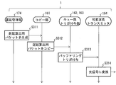
- FIG. 12 is a sequence diagram showing details of the reception side process of S34. This sequence is executed by the first synchronization module 10 in the first transmission device 1.
- the coupler 171 branches the optical signals of two wavelengths to the time difference detection unit 172 and the optical reception unit 175 and outputs the branched optical signals.
- the optical receiver 175 outputs the received optical signal to the identification selector 176.
- the identification selector 176 selects one from the optical signals of two wavelengths and outputs it to the delay management unit 174.
- the time difference detection unit 172 detects the arrival time difference ( ⁇ t21) of the optical signal based on the trigger by the trigger giving unit 163, and outputs the result to the delay calculation unit 173.
- the delay calculation unit 173 calculates the propagation delay Dsm from the arrival time difference of the optical signals, and outputs the result to the delay management unit 174, as shown in FIG.
- the delay management unit 174 holds information on the propagation delay Dsm of S343.
- the delay management unit 174 holds the information on the propagation delay Dms read from the unique packet notified from step S341c.
- the delay management unit 174 determines whether or not both the propagation delays Dms and Dsm are held.
- the delay management unit 174 determines the propagation delay Dmax, which is larger than the maximum value of the propagation delays Dms and Dsm, as shown in FIG. 2, and outputs the result to the delay amount control unit 177.
- the delay amount control unit 177 holds information on the propagation delay Dmax.
- FIG. 13 is a sequence diagram showing details of the transmission side processing of S35. This sequence is executed by the first synchronization module 10 in the first transmission device 1.
- the delay management unit 174 newly generates the propagation delay Dmax notification packet as a unique packet and outputs it to the copy unit 161.
- the copy unit 161 copies the propagation delay Dmax notification packet and outputs it to the queue unit 162 for two wavelengths.
- the propagation delay Dmax notification packet that has undergone the buffering process by the queue unit 162 and the trigger applying process by the trigger applying unit 163 is output to the variable wavelength transmitter 164.
- the variable wavelength transmitter 164 converts the propagation delay Dmax notification packet for two wavelengths into an optical signal, and outputs the optical signal to the second synchronization module 20 at the same time.
- FIG. 14 is a sequence diagram showing details of the reception side processing of S36. This sequence is executed by the second synchronization module 20 in the second transmission device 2.
- the coupler 171 branches the optical signals of two wavelengths to the time difference detection unit 172 and the optical reception unit 175 and outputs the branched optical signals.
- the time difference detection unit 172 discards the output optical signal.
- the optical receiver 175 outputs the received optical signal to the identification selector 176.
- the identification selector 176 selects one propagation delay Dmax notification packet from the optical signals of two wavelengths and outputs it to the delay management unit 174.
- the delay management unit 174 holds the information on the propagation delay Dmax read from the propagation delay Dmax notification packet, and outputs the result to the delay amount control unit 177.
- the delay amount control unit 177 holds information on the propagation delay Dmax.
- FIG. 15 is a sequence diagram showing details of the transmission side processing of S12. This sequence is executed by the first synchronization module 10 in the first transmission device 1.
- the delay management unit 174 performs various processing (processing of the O/E/E/O unit 11, processing of the PHY unit 12, processing of the MAC unit 13) performed by the common unit 19 when receiving the PTP packet, The result is output to the copy unit 161.
- the copy unit 161 copies the PTP packet and outputs it to the queue unit 162 for two wavelengths.
- the PTP packet subjected to the buffering process by the queue unit 162 and the trigger giving process by the trigger giving unit 163 is output to the variable wavelength transmitter 164.
- the variable wavelength transmitter 164 converts the PTP packet for two wavelengths into an optical signal and outputs the optical signal to the second synchronization module 20 at the same time.
- FIG. 16 is a sequence diagram showing details of the reception side process of S13. This sequence is executed by the second synchronization module 20 in the second transmission device 2.
- the coupler 171 branches the optical signals of two wavelengths to the time difference detection unit 172 and the optical reception unit 175 and outputs the branched optical signals.
- the optical receiver 175 outputs the received optical signal to the identification selector 176.
- the identification selector 176 selects one PTP packet from the optical signals of two wavelengths and outputs it to the variable delay unit 178 as a queuing target.
- the time difference detection unit 172 detects the arrival time difference ( ⁇ t12) of the optical signal based on the trigger by the trigger giving unit 163, and outputs the result to the delay calculation unit 173.
- the delay calculation unit 173 calculates the propagation delay Dms from the arrival time difference of the optical signals as shown in FIG. 7, and outputs the result to the delay amount control unit 177 via the delay management unit 174.
- step S135 the variable delay unit 178 waits for the PTP packet of step S131c by the delay Wms and then outputs the delayed PTP packet to the common unit 19.
- the common unit 19 performs various processes (process of the MAC unit 13, process of the PHY unit 12, process of the O/E/E/O unit 11) at the time of transmitting the PTP packet, and then transmits the PTP packet of S14. Perform processing.
- the delay asymmetry that occurs between the master node 3 and the slave node 4 causes the transmission device (first transmission device 1, second transmission device 2) located at the relay point.
- the main feature is to correct (absorb) by ). That is, in the transmission device near the end point of the path of the PTP packet, the waiting delays Wms and Wsm are arbitrarily generated, so that the bidirectional propagation delays are both corrected to Dmax (to be symmetrical). ..
- Dmax an original packet for two wavelengths is transmitted and received in advance between the first synchronization module 10 and the second synchronization module 20 provided in the transmission device, and synchronization is performed from the arrival time difference of the original packet. Propagation delays Dms and Dsm between modules are calculated with high accuracy.
- the error factor (delay asymmetry) of PTP which is a time synchronization protocol, can be eliminated, and highly accurate time synchronization between geographically distant locations becomes possible.
- the propagation delay Dms and Dsm including the delay in the device on the way of the transmission path and (b) the delay of the transmission path are measured with high accuracy, and the propagation delay Dmax is the first synchronization based on the measurement result.
- Module 10 and second synchronization module 20 see FIG. 2).
- an excessively large value is set as the propagation delay Dmax to make the PTP packet wait for an extra amount, or an excessively small value is set as the propagation delay Dmax to eliminate the delay asymmetry of the PTP packet. It is possible to prevent inconveniences such as not being able to run out.
- the program for operating the control unit of the first synchronization module 10 and the second synchronization module 20 may be distributed via a communication line or may be recorded in a recording medium such as a CD-ROM and distributed. It is also possible.
Landscapes
- Engineering & Computer Science (AREA)
- Computer Networks & Wireless Communication (AREA)
- Signal Processing (AREA)
- Physics & Mathematics (AREA)
- General Physics & Mathematics (AREA)
- Synchronisation In Digital Transmission Systems (AREA)
- Data Exchanges In Wide-Area Networks (AREA)
- Electric Clocks (AREA)
Abstract
【課題】時刻同期装置間のリンク非対称性の影響を低減するような時刻同期機構を提供すること。 【解決手段】第2伝送装置2は、複数波長分の遅延算出用パケットを同時に対向の時刻伝送装置に送信する送信部16と、対向の時刻伝送装置から受信した複数波長分の遅延算出用パケットの到着した時刻の差をもとに、対向の時刻伝送装置から自装置までの伝搬遅延Dmsを求め、対向の時刻伝送装置が求めた自装置から対向の時刻伝送装置までの伝搬遅延Dsmの通知を受け、伝搬遅延Dmsおよび伝搬遅延Dsmよりも大きな伝搬遅延Dmaxを求める受信部17とを有する。受信部17は、受信したPTPパケットに対して、伝搬遅延Dmsから伝搬遅延Dmaxまでの待ちあわせ遅延Wmsを発生させた後に、スレーブノード4に送信する。
Description
本発明は、伝送装置、時刻伝送システム、および、遅延補正方法に関する。
時刻同期技術は、モバイルにおける基地局間連携において次世代移動通信5G(Generation)などで今後必要とされている。時刻同期システムは、例えば、時刻基準装置であるGM(Grand Master)を各地点に分散配置させる構成により実現される。各地点のGMは、GNSS(Global Navigation Satellite System)衛星からの信号を直接受信するGNSSレシーバとして機能し、受信した信号を直接エンドアプリケーションに配信する。
しかし、高性能であるGNSSレシーバの台数を増やすと、その分コストも高くなってしまう。また、悪天候により衛星からの信号を受信できない時間帯は、時刻の精度が悪化してしまう。
しかし、高性能であるGNSSレシーバの台数を増やすと、その分コストも高くなってしまう。また、悪天候により衛星からの信号を受信できない時間帯は、時刻の精度が悪化してしまう。
そこで、GMからの情報をパケットネットワークによって配信する(つまり、GNSS信号を間接的に受信する)形態として、例えば、パケットのタイムスタンプを利用して時刻同期を行うPTP(Precision Time Protocol)が用いられる(非特許文献1)。PTPでは、通信事業者の高信頼なネットワークを介して時刻同期が行われる。
これにより、時刻基準となるGNSSアンテナの受信地点および設置数を集約でき、集約したGNSSレシーバ(GM)へ監視機能を具備することでGNSS受信の信頼性を向上することができる。また、パケットネットワークの経路二重化により、信頼性も向上できる。さらに、GMはPTPパケットを主信号に重畳することで、経済的かつ高精度に時刻情報を伝達することができる。
これにより、時刻基準となるGNSSアンテナの受信地点および設置数を集約でき、集約したGNSSレシーバ(GM)へ監視機能を具備することでGNSS受信の信頼性を向上することができる。また、パケットネットワークの経路二重化により、信頼性も向上できる。さらに、GMはPTPパケットを主信号に重畳することで、経済的かつ高精度に時刻情報を伝達することができる。
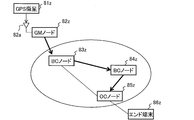
図17は、時刻同期技術が適用された時刻伝送システムの構成図である。
時刻伝送システムは、PTPに対応したPTPノードであるGMノード82zと、BC(Boundary Clock)ノード83z,84zと、OC(Ordinary Clock)ノード85zとがネットワークで接続されて構成される。
以下、時刻同期を直接行うPTPノード間で、時刻情報を提供する側をマスタノード91z(図18)とし、マスタノード91zから時刻情報を受ける被同期装置の側をスレーブノード92z(図18)とする。以下、時刻情報の伝搬の順序を図17の太線矢印で記載する。太線矢印の矢印元側が上り側であり、太線矢印の矢印先側が下り側である。つまり、GMノード82z→BCノード83z→BCノード84z→OCノード85zの順に正確な時刻情報が下りに伝搬される。
時刻伝送システムは、PTPに対応したPTPノードであるGMノード82zと、BC(Boundary Clock)ノード83z,84zと、OC(Ordinary Clock)ノード85zとがネットワークで接続されて構成される。
以下、時刻同期を直接行うPTPノード間で、時刻情報を提供する側をマスタノード91z(図18)とし、マスタノード91zから時刻情報を受ける被同期装置の側をスレーブノード92z(図18)とする。以下、時刻情報の伝搬の順序を図17の太線矢印で記載する。太線矢印の矢印元側が上り側であり、太線矢印の矢印先側が下り側である。つまり、GMノード82z→BCノード83z→BCノード84z→OCノード85zの順に正確な時刻情報が下りに伝搬される。
GMノード82zは、GPS衛星81zからの信号を直接受信するアンテナ82aを備える。
BCノード83zは、マスタノード91zであるGMノード82zから時刻情報を受けるスレーブノード92zであり、その後にBCノード84zに時刻情報を提供するマスタノード91zとして機能する。
BCノード84zは、BCノード83zから時刻情報を受けるスレーブノード92zであり、その後にOCノード85zに時刻情報を提供するマスタノード91zとして機能する。
OCノード85zは、BCノード84zから時刻情報を受けるスレーブノード92zであり、その後にエンド端末86zに時刻情報を提供する。
なお、BCノード83z,84zとOCノード85zとの呼び方の違いは、他PTPノードへの接続ポートがBCノード83z,84zには複数本存在し、OCノード85zには1本だけ存在することによる。
BCノード83zは、マスタノード91zであるGMノード82zから時刻情報を受けるスレーブノード92zであり、その後にBCノード84zに時刻情報を提供するマスタノード91zとして機能する。
BCノード84zは、BCノード83zから時刻情報を受けるスレーブノード92zであり、その後にOCノード85zに時刻情報を提供するマスタノード91zとして機能する。
OCノード85zは、BCノード84zから時刻情報を受けるスレーブノード92zであり、その後にエンド端末86zに時刻情報を提供する。
なお、BCノード83z,84zとOCノード85zとの呼び方の違いは、他PTPノードへの接続ポートがBCノード83z,84zには複数本存在し、OCノード85zには1本だけ存在することによる。
図18は、PTPの仕組みを示すシーケンス図である。
時刻情報(タイムスタンプ)を付与したPTPパケットは、マスタノード91z~スレーブノード92z間で送受信される。PTPパケットとして、下りのSyncメッセージ(S11z)と、下りのFollow-upメッセージ(S12z)と、上りのDelay_Requestメッセージ(S13z)と、下りのDelay_Responseメッセージ(S14z)とが順番に送受信される。
発時刻t1は、Syncメッセージ(S11z)がマスタノード91zから送信された時刻である。なお、Syncメッセージの発時刻t1をSyncメッセージそのものに含ませることは困難であるので、Syncメッセージの発時刻t1は後続のFollow-upメッセージにて、スレーブノード92zに通知される。
着時刻t2は、Syncメッセージがスレーブノード92zに到着した時刻である。
発時刻t3は、Delay_Requestメッセージがスレーブノード92zから送信された時刻である。
着時刻t4は、Delay_Requestメッセージがマスタノード91zに到着した時刻である。着時刻t4は、Delay_Requestメッセージに対するDelay_Responseメッセージに含めて、スレーブノード92zに通知される。
これにより、スレーブノード92zは、4つのタイムスタンプ(発時刻t1~着時刻t4)をすべて把握できる。
時刻情報(タイムスタンプ)を付与したPTPパケットは、マスタノード91z~スレーブノード92z間で送受信される。PTPパケットとして、下りのSyncメッセージ(S11z)と、下りのFollow-upメッセージ(S12z)と、上りのDelay_Requestメッセージ(S13z)と、下りのDelay_Responseメッセージ(S14z)とが順番に送受信される。
発時刻t1は、Syncメッセージ(S11z)がマスタノード91zから送信された時刻である。なお、Syncメッセージの発時刻t1をSyncメッセージそのものに含ませることは困難であるので、Syncメッセージの発時刻t1は後続のFollow-upメッセージにて、スレーブノード92zに通知される。
着時刻t2は、Syncメッセージがスレーブノード92zに到着した時刻である。
発時刻t3は、Delay_Requestメッセージがスレーブノード92zから送信された時刻である。
着時刻t4は、Delay_Requestメッセージがマスタノード91zに到着した時刻である。着時刻t4は、Delay_Requestメッセージに対するDelay_Responseメッセージに含めて、スレーブノード92zに通知される。
これにより、スレーブノード92zは、4つのタイムスタンプ(発時刻t1~着時刻t4)をすべて把握できる。
PTPパケットの送受信には、以下の伝搬遅延が発生する。
・下り遅延Dmsは、マスタノード91z→スレーブノード92zの下り方向のSyncメッセージの伝搬遅延である。マスタノード91z側の時計に対するスレーブノード92z側の時計のずれをオフセット値とすると、下り遅延Dms=(着時刻t2-オフセット値)-発時刻t1で求まる。
・上り遅延Dsmは、スレーブノード92z→マスタノード91zの上り方向のDelay_Requestメッセージの伝搬遅延である。上り遅延Dsm=着時刻t4-(発時刻t3-オフセット値)で求まる。
下り遅延Dms=上り遅延Dsmと仮定すると、スレーブノード92zは、以下の数式1でオフセット値を求める。
オフセット値=((着時刻t2-発時刻t1)-(着時刻t4-発時刻t3))/2 …(数式1)
そして、スレーブノード92zは、求めたオフセット値で自身の時計の時刻を修正することで、マスタノード91zの時計とスレーブノード92zの時計とが同期(時刻一致)される。
・下り遅延Dmsは、マスタノード91z→スレーブノード92zの下り方向のSyncメッセージの伝搬遅延である。マスタノード91z側の時計に対するスレーブノード92z側の時計のずれをオフセット値とすると、下り遅延Dms=(着時刻t2-オフセット値)-発時刻t1で求まる。
・上り遅延Dsmは、スレーブノード92z→マスタノード91zの上り方向のDelay_Requestメッセージの伝搬遅延である。上り遅延Dsm=着時刻t4-(発時刻t3-オフセット値)で求まる。
下り遅延Dms=上り遅延Dsmと仮定すると、スレーブノード92zは、以下の数式1でオフセット値を求める。
オフセット値=((着時刻t2-発時刻t1)-(着時刻t4-発時刻t3))/2 …(数式1)
そして、スレーブノード92zは、求めたオフセット値で自身の時計の時刻を修正することで、マスタノード91zの時計とスレーブノード92zの時計とが同期(時刻一致)される。
IEEE(The Institute of Electrical and Electronics Engineers, Inc.)、「IEEE Standard for a Precision Clock Synchronization Protocol for Networked Measurement and Control Systems」、IEEE Std 1588-2008,Revision of IEEE Std 1588-2002、2008年7月24日
PTPは、PTPパケットの伝送経路について、上り下りの遅延が等しいことを前提としたプロトコルである。よって、リンク非対称性(上り下りの遅延差)が発生する場合には、時刻同期精度に誤差が生じる。以下、リンク非対称性の要因を例示する。
(a)伝送経路途中の装置内遅延は、例えば、パケット処理によるバッファリングやフレーム処理による変動可能性がある遅延である。
(b)伝送路の遅延は、例えば、光路長1mの差で5ns遅延する(5ns/m)など二芯双方向通信時のファイバ長差の遅延や、伝送路の温度変動による変動可能性がある遅延である。なお、地理的に離れた拠点間の時刻誤差は、局内配線の光路長差に比例して大きくなる。
(a)伝送経路途中の装置内遅延は、例えば、パケット処理によるバッファリングやフレーム処理による変動可能性がある遅延である。
(b)伝送路の遅延は、例えば、光路長1mの差で5ns遅延する(5ns/m)など二芯双方向通信時のファイバ長差の遅延や、伝送路の温度変動による変動可能性がある遅延である。なお、地理的に離れた拠点間の時刻誤差は、局内配線の光路長差に比例して大きくなる。
そこで、本発明は、時刻同期装置間のリンク非対称性の影響を低減するような時刻同期機構を提供することを、主な課題とする。
前記課題を解決するために、本発明の伝送装置は、以下の特徴を有する。
本発明は、第1時刻同期装置側に接続される第1伝送装置と、前記第1伝送装置に対向し第2時刻同期装置側に接続される第2伝送装置を経由して、前記第1時刻同期装置と前記第2時刻同期装置との間で時刻同期用パケットを送受信し、その送受信の時刻情報をもとに前記第2時刻同期装置の時刻を同期する時刻伝送システムに用いられる伝送装置であって、
前記第1伝送装置および前記第2伝送装置としてそれぞれ動作する伝送装置が、
複数波長分の遅延算出用パケットを同時に対向の伝送装置に送信する送信部と、
前記対向の伝送装置から受信した複数波長分の前記遅延算出用パケットの到着した時刻の差をもとに、前記対向の伝送装置から自装置までの第1伝搬遅延を求め、前記対向の伝送装置が求めた自装置から前記対向の伝送装置までの第2伝搬遅延の通知を受け、前記第1伝搬遅延および前記第2伝搬遅延よりも大きな設定遅延を求める受信部とを有し、
前記受信部が、
前記対向の伝送装置から複数波長分の前記時刻同期用パケットを受信すると、それらの前記時刻同期用パケットの到着した時刻の差をもとに、前記対向の伝送装置から自装置までの第3伝搬遅延を求め、
受信した前記時刻同期用パケットに対して、前記第3伝搬遅延から前記設定遅延までの待ちあわせ遅延を発生させた後に、自装置側に接続される時刻同期装置に送信することを特徴とする。
本発明は、第1時刻同期装置側に接続される第1伝送装置と、前記第1伝送装置に対向し第2時刻同期装置側に接続される第2伝送装置を経由して、前記第1時刻同期装置と前記第2時刻同期装置との間で時刻同期用パケットを送受信し、その送受信の時刻情報をもとに前記第2時刻同期装置の時刻を同期する時刻伝送システムに用いられる伝送装置であって、
前記第1伝送装置および前記第2伝送装置としてそれぞれ動作する伝送装置が、
複数波長分の遅延算出用パケットを同時に対向の伝送装置に送信する送信部と、
前記対向の伝送装置から受信した複数波長分の前記遅延算出用パケットの到着した時刻の差をもとに、前記対向の伝送装置から自装置までの第1伝搬遅延を求め、前記対向の伝送装置が求めた自装置から前記対向の伝送装置までの第2伝搬遅延の通知を受け、前記第1伝搬遅延および前記第2伝搬遅延よりも大きな設定遅延を求める受信部とを有し、
前記受信部が、
前記対向の伝送装置から複数波長分の前記時刻同期用パケットを受信すると、それらの前記時刻同期用パケットの到着した時刻の差をもとに、前記対向の伝送装置から自装置までの第3伝搬遅延を求め、
受信した前記時刻同期用パケットに対して、前記第3伝搬遅延から前記設定遅延までの待ちあわせ遅延を発生させた後に、自装置側に接続される時刻同期装置に送信することを特徴とする。
これにより、時刻同期装置間でリンク非対称性を吸収する一定の設定遅延が時刻同期用パケットに設定されるので、時刻同期装置間のリンク非対称性に影響されない時刻同期機構を提供することができる。
本発明は、前記伝送装置と、前記第1時刻同期装置と、前記第2時刻同期装置とを含めて構成される時刻伝送システムであって、
前記第2時刻同期装置が、前記時刻同期用パケットの前記時刻同期装置間における発時刻および着時刻を用いて前記第2時刻同期装置の時計のずれであるオフセット値を計算することを特徴とする。
前記第2時刻同期装置が、前記時刻同期用パケットの前記時刻同期装置間における発時刻および着時刻を用いて前記第2時刻同期装置の時計のずれであるオフセット値を計算することを特徴とする。
これにより、時刻同期装置間のリンク非対称性に影響されない時刻同期用パケットの発時刻および着時刻をもとに、高精度な時刻同期を実現することができる。
本発明によれば、時刻同期装置間のリンク非対称性の影響を低減するような時刻同期機構を提供することができる。
以下、本発明の一実施形態について、図面を参照して詳細に説明する。
図1は、時刻同期技術が適用された時刻伝送システムの構成図である。
本実施形態の時刻伝送システムでは、時刻同期装置としてのマスタノード(第1時刻同期装置)3とスレーブノード(第2時刻同期装置)4との間でPTPパケット(時刻同期用パケット)を送受信することで、スレーブノード4の時刻同期処理を行う。
そして、PTPパケットを中継するための伝送装置として、第1伝送装置1と、第2伝送装置2とを互いに対向するように設ける。直接接続されるマスタノード3と第1伝送装置1とが組となり、直接接続されるスレーブノード4と第2伝送装置2とが組となる。これらの伝送装置は、パケットの中継機能に加えて、マスタノード3とスレーブノード4との間のリンク非対称性の影響を低減する待ち合わせ機能(詳細は図3)を有している。
本実施形態の時刻伝送システムでは、時刻同期装置としてのマスタノード(第1時刻同期装置)3とスレーブノード(第2時刻同期装置)4との間でPTPパケット(時刻同期用パケット)を送受信することで、スレーブノード4の時刻同期処理を行う。
そして、PTPパケットを中継するための伝送装置として、第1伝送装置1と、第2伝送装置2とを互いに対向するように設ける。直接接続されるマスタノード3と第1伝送装置1とが組となり、直接接続されるスレーブノード4と第2伝送装置2とが組となる。これらの伝送装置は、パケットの中継機能に加えて、マスタノード3とスレーブノード4との間のリンク非対称性の影響を低減する待ち合わせ機能(詳細は図3)を有している。
時刻伝送システムは、マスタノード3→第1伝送装置1→第2伝送装置2→スレーブノード4の経路で下りのSyncメッセージ(図18ではS11z)を伝送し、その逆の経路で上りのDelay_Requestメッセージ(図18ではS13z)を伝送する。
マスタノード3→スレーブノード4の伝搬遅延の主成分である第1伝送装置1→第2伝送装置2の間に発生する伝搬遅延を、以下では「Dms」(第1伝搬遅延)とする。
スレーブノード4→マスタノード3の伝搬遅延の主成分である第2伝送装置2→第1伝送装置1の間に発生する伝搬遅延を、以下では「Dsm」(第2伝搬遅延)とする。
なお、伝搬遅延Dmsの「ms」はmaster→slaveの方向を示し、伝搬遅延Dsmの「sm」はslave→masterの方向を示す。
マスタノード3→スレーブノード4の伝搬遅延の主成分である第1伝送装置1→第2伝送装置2の間に発生する伝搬遅延を、以下では「Dms」(第1伝搬遅延)とする。
スレーブノード4→マスタノード3の伝搬遅延の主成分である第2伝送装置2→第1伝送装置1の間に発生する伝搬遅延を、以下では「Dsm」(第2伝搬遅延)とする。
なお、伝搬遅延Dmsの「ms」はmaster→slaveの方向を示し、伝搬遅延Dsmの「sm」はslave→masterの方向を示す。
このとき、|伝搬遅延Dms-伝搬遅延Dsm|>0なら時刻同期装置間のリンク非対称性が存在し、その要因は伝送経路途中の装置(第1伝送装置1、第2伝送装置2)内遅延と、伝送路の遅延との和である。このリンク非対称性を削減するために、第1伝送装置1→第2伝送装置2間の伝搬遅延Dmsをマスタノード3→スレーブノード4間の遅延の代わりに測定し、第2伝送装置2→第1伝送装置1間の伝搬遅延Dsmをスレーブノード4→マスタノード3間の遅延の代わりに測定する。
なお、時刻伝送システムに対して、以下に示す構成を採用することにより、伝送装置間の非対称性と、時刻同期装置間の非対称性とがほぼ等しくなる。
・マスタノード3、第1伝送装置1間の配線と、第2伝送装置2、スレーブノード4間の配線とが上り下りで等長配線である構成。
・第1同期用モジュール10をマスタノード3の内部に組み込み、第2同期用モジュール20をスレーブノード4の内部に組み込む構成。
なお、時刻伝送システムに対して、以下に示す構成を採用することにより、伝送装置間の非対称性と、時刻同期装置間の非対称性とがほぼ等しくなる。
・マスタノード3、第1伝送装置1間の配線と、第2伝送装置2、スレーブノード4間の配線とが上り下りで等長配線である構成。
・第1同期用モジュール10をマスタノード3の内部に組み込み、第2同期用モジュール20をスレーブノード4の内部に組み込む構成。
図2は、伝送装置(第1伝送装置1、第2伝送装置2)内での遅延の計算方法を示す説明図である。
(手順1)伝搬遅延Dmsおよび伝搬遅延Dsmがそれぞれ遅延量として測定される。
(手順2)遅延量の最大値に対してある程度のマージンを加算した伝搬遅延Dmax(設定遅延)が求まる。つまり、伝搬遅延Dmaxは、どの伝搬遅延Dmsおよび伝搬遅延Dsmよりも大きな値が設定される。
(手順3)各伝送装置は、自身が受信したPTPパケットに対して、そのPTPパケットの送信元から自身までに要した伝搬遅延(第3伝搬遅延)から伝搬遅延Dmaxまでの不足分を待ちあわせ遅延とする。
[第2伝送装置2の場合]下りのPTPパケットの待ちあわせ遅延Wms=伝搬遅延Dmax-伝搬遅延Dms
[第1伝送装置1の場合]上りのPTPパケットの待ちあわせ遅延Wsm=伝搬遅延Dmax-伝搬遅延Dsm
(手順1)伝搬遅延Dmsおよび伝搬遅延Dsmがそれぞれ遅延量として測定される。
(手順2)遅延量の最大値に対してある程度のマージンを加算した伝搬遅延Dmax(設定遅延)が求まる。つまり、伝搬遅延Dmaxは、どの伝搬遅延Dmsおよび伝搬遅延Dsmよりも大きな値が設定される。
(手順3)各伝送装置は、自身が受信したPTPパケットに対して、そのPTPパケットの送信元から自身までに要した伝搬遅延(第3伝搬遅延)から伝搬遅延Dmaxまでの不足分を待ちあわせ遅延とする。
[第2伝送装置2の場合]下りのPTPパケットの待ちあわせ遅延Wms=伝搬遅延Dmax-伝搬遅延Dms
[第1伝送装置1の場合]上りのPTPパケットの待ちあわせ遅延Wsm=伝搬遅延Dmax-伝搬遅延Dsm
図3は、図1の時刻伝送システムに対して、リンク対称性が事後的に確立される場合の構成図である。
第2伝送装置2は、図2で説明したように、伝搬遅延Dmsで到着したPTPパケットに対して待ちあわせ遅延Wms分待たせるようにすることで、伝送路の合計の遅延が伝搬遅延Dmaxとなる。
第1伝送装置1も、図2で説明したように、伝搬遅延Dsmで到着したPTPパケットに対して待ちあわせ遅延Wsm分待たせるようにすることで、伝送路の合計の遅延が伝搬遅延Dmaxとなる。
これにより、上り下りの両方向の遅延が等しくなることで、リンク対称性が事後的に確立される。例えば、同じ経路のPTPパケットでも、送信するタイミングにおけるネットワークの混雑状況により、同じ方向の通信でも遅延がばらついてしまう。しかし、この遅延のばらつきも伝搬遅延Dmax への不足分だけ各伝送装置内で待ち合わせを行うことで、全パケットが同じ遅延となる。
第2伝送装置2は、図2で説明したように、伝搬遅延Dmsで到着したPTPパケットに対して待ちあわせ遅延Wms分待たせるようにすることで、伝送路の合計の遅延が伝搬遅延Dmaxとなる。
第1伝送装置1も、図2で説明したように、伝搬遅延Dsmで到着したPTPパケットに対して待ちあわせ遅延Wsm分待たせるようにすることで、伝送路の合計の遅延が伝搬遅延Dmaxとなる。
これにより、上り下りの両方向の遅延が等しくなることで、リンク対称性が事後的に確立される。例えば、同じ経路のPTPパケットでも、送信するタイミングにおけるネットワークの混雑状況により、同じ方向の通信でも遅延がばらついてしまう。しかし、この遅延のばらつきも伝搬遅延Dmax への不足分だけ各伝送装置内で待ち合わせを行うことで、全パケットが同じ遅延となる。
図4は、第1伝送装置1の構成図である。第1伝送装置1は、光信号を中継するWDM(Wavelength Division Multiplexing)技術を適用した装置として構成される。第1伝送装置1は、基本的なパケット伝送部として、TRPN(Transponder)91と、MUX(multiplexer)92と、DEMUX(demultiplexer)93と、OXC(Optical Cross Connect)94と、AMP(Amplifier)95,96と、OSC(Optical Supervisory Channel)97とを有する。
これらの基本的なパケット伝送部は、第1伝送装置1内に1度導入した後には、基本的には交換しなくてもよい部品である。例外として、通信需要が急増したり、部品が故障したりする場合は交換または追加配備が必要となる。
これらの基本的なパケット伝送部は、第1伝送装置1内に1度導入した後には、基本的には交換しなくてもよい部品である。例外として、通信需要が急増したり、部品が故障したりする場合は交換または追加配備が必要となる。
さらに、第1伝送装置1は、PTPパケットに加え、伝搬遅延Dms、Dsmを測定するための独自パケットを用いた時刻同期処理を扱う処理部として、第1同期用モジュール10を有する。第1同期用モジュール10は、接続先のマスタノード3との間でPTPパケットを送受信する。つまり、第1伝送装置1は、基本的なパケット伝送部に修正を加えること無く、独立した別部品として第1同期用モジュール10を装置内に追加することができる。これにより、図1~図3で説明したリンク対称性を確立する機能を低コストで追加することができる。
一方、TRPN91は、マスタノード3以外の一般的なルータや転送装置と接続し、パケットを送受信する。
第1同期用モジュール10およびTRPN91から送信される光信号は、MUX92、OXC94、AMP95、OSC97を経由して、光ネットワークへと出力される。なお、OSC97では、伝送路の監視や装置の制御が行われる。
光ネットワークから受信した光信号は、OSC97、AMP96、OXC94、MUX92、DEMUX93を経由して、第1同期用モジュール10およびTRPN91へと通知される。
第1同期用モジュール10およびTRPN91から送信される光信号は、MUX92、OXC94、AMP95、OSC97を経由して、光ネットワークへと出力される。なお、OSC97では、伝送路の監視や装置の制御が行われる。
光ネットワークから受信した光信号は、OSC97、AMP96、OXC94、MUX92、DEMUX93を経由して、第1同期用モジュール10およびTRPN91へと通知される。
図5は、第2伝送装置2の構成図である。第2伝送装置2も第1伝送装置1と同様に、基本的なパケット伝送部として、TRPN91と、MUX92と、DEMUX93と、OXC94と、AMP95,96と、OSC97とを有する。基本的なパケット伝送部の機能は、第1伝送装置1も第2伝送装置2も同じであるので、図5では説明を省略する。
そして、第2伝送装置2は、PTPパケット、独自パケットを用いた時刻同期処理を扱う処理部として、第2同期用モジュール20を有する。第2同期用モジュール20は、接続先のスレーブノード4との間でPTPパケットを送受信する。
そして、第2伝送装置2は、PTPパケット、独自パケットを用いた時刻同期処理を扱う処理部として、第2同期用モジュール20を有する。第2同期用モジュール20は、接続先のスレーブノード4との間でPTPパケットを送受信する。
図6は、第1同期用モジュール10、第2同期用モジュール20の構成図である。これらの両モジュールは共通の構成である。
両モジュールの構成要素の一部である制御部は、それぞれCPU(Central Processing Unit)と、メモリと、ハードディスク、不揮発メモリ、SSD(solid state drive)などで例示される記憶手段(記憶部)と、ネットワークインタフェースとを有するコンピュータとして構成してもよい。
制御部のコンピュータは、CPUが、メモリ上に読み込んだプログラム(アプリケーションや、その略のアプリとも呼ばれる)を実行することにより、各処理部を動作させる。
さらに、O/E・E/O部11、可変波長トランスミッタ164、カプラ171、光受信部175はそれぞれ個別のハード(ハードウェア)として構成される。また、PHY部12、MAC部13は、LSI(Large Scale Integration)として構成される。
両モジュールの構成要素の一部である制御部は、それぞれCPU(Central Processing Unit)と、メモリと、ハードディスク、不揮発メモリ、SSD(solid state drive)などで例示される記憶手段(記憶部)と、ネットワークインタフェースとを有するコンピュータとして構成してもよい。
制御部のコンピュータは、CPUが、メモリ上に読み込んだプログラム(アプリケーションや、その略のアプリとも呼ばれる)を実行することにより、各処理部を動作させる。
さらに、O/E・E/O部11、可変波長トランスミッタ164、カプラ171、光受信部175はそれぞれ個別のハード(ハードウェア)として構成される。また、PHY部12、MAC部13は、LSI(Large Scale Integration)として構成される。
第1同期用モジュール10、第2同期用モジュール20は、それぞれPTPパケット、独自パケットの送信を行う送信部16と、PTPパケット、独自パケットの受信を行う受信部17と、その他の共通部19とを有する。共通部19は、O/E・E/O(Optical/Electronic・Electronic/Optical signal converter)部11と、PHY(physical layer:物理層)部12と、MAC(Medium Access Control)部13と、クロックタイマ14と、環境情報管理部15とを有する。
クロックタイマ14は、第1同期用モジュール10内の任意の機能部間の同期動作を担保するために、周波数・タイミングを供給する。
環境情報管理部15は、波長分散係数、温度の情報を管理する。
クロックタイマ14は、第1同期用モジュール10内の任意の機能部間の同期動作を担保するために、周波数・タイミングを供給する。
環境情報管理部15は、波長分散係数、温度の情報を管理する。
送信部16は、キュー部162と、トリガ付与部163と、可変波長トランスミッタ164とが2波長(2波長)分用意され、その各系統に対して同じパケットをコピーして入力するためのコピー部161,165も備えられている。
コピー部161は、PTPパケットを2波長にコピーする。
キュー部162は、これから送信するPTPパケット、独自パケットを格納する。
トリガ付与部163は、時間差検出部172の到着時間差を検出用のトリガを、これから送信するPTPパケット、独自パケットに付与する。トリガとは、例えば、Ethernet(登録商標)のプリアンブルのような、測定対象のタイミングを認識できるような特定の信号パターン(「101010…11」など)として実装される。または、パケット内の特定フィールドの特定値として、トリガを埋め込んでもよい。
2波長それぞれの可変波長トランスミッタ164は、送信するPTPパケット、独自パケットを他方の可変波長トランスミッタ164とは異なる波長の光信号に変換する。そして、2波長それぞれの可変波長トランスミッタ164は、変換した光信号を他方の可変波長トランスミッタ164と同時に送信する。なお、2波長を例示したが、3波長以上の光信号を3つ以上の可変波長トランスミッタ164が同時に送信してもよい。
コピー部165は、独自パケットを2波長にコピーする。
コピー部161は、PTPパケットを2波長にコピーする。
キュー部162は、これから送信するPTPパケット、独自パケットを格納する。
トリガ付与部163は、時間差検出部172の到着時間差を検出用のトリガを、これから送信するPTPパケット、独自パケットに付与する。トリガとは、例えば、Ethernet(登録商標)のプリアンブルのような、測定対象のタイミングを認識できるような特定の信号パターン(「101010…11」など)として実装される。または、パケット内の特定フィールドの特定値として、トリガを埋め込んでもよい。
2波長それぞれの可変波長トランスミッタ164は、送信するPTPパケット、独自パケットを他方の可変波長トランスミッタ164とは異なる波長の光信号に変換する。そして、2波長それぞれの可変波長トランスミッタ164は、変換した光信号を他方の可変波長トランスミッタ164と同時に送信する。なお、2波長を例示したが、3波長以上の光信号を3つ以上の可変波長トランスミッタ164が同時に送信してもよい。
コピー部165は、独自パケットを2波長にコピーする。
受信部17は、カプラ171と、時間差検出部172と、遅延演算部173と、遅延管理部174と、光受信部175と、識別セレクタ176と、遅延量制御部177と、可変遅延部178とを有する。
カプラ171は、可変波長トランスミッタ164から送信された2波長以上の光信号を受信し、時間差検出部172と、光受信部175とに出力する。
時間差検出部172は、2波長以上の光信号の到着時間差△tを検出する(詳細は図7)。なお、時間差検出部172は、例えばオシロスコープに具備されている機能群を用いることによって実現できる。
遅延演算部173は、到着時間差△tから伝搬遅延Dms、Dsmを算出する(詳細は図7)。
カプラ171は、可変波長トランスミッタ164から送信された2波長以上の光信号を受信し、時間差検出部172と、光受信部175とに出力する。
時間差検出部172は、2波長以上の光信号の到着時間差△tを検出する(詳細は図7)。なお、時間差検出部172は、例えばオシロスコープに具備されている機能群を用いることによって実現できる。
遅延演算部173は、到着時間差△tから伝搬遅延Dms、Dsmを算出する(詳細は図7)。
遅延管理部174は、図2で示したように、第1同期用モジュール10、第2同期用モジュール20間で、算出された伝搬遅延Dms、Dsmをやりとりし、待ちあわせ遅延Wms、Wsmを決定し、伝送区間の遅延が伝搬遅延Dmaxとなるように(同じ値で対称性をもつように)調整する。
光受信部175は、カプラ171からの光信号を電気信号に変換する。この変換時に分散補償などの処理を行ってもよい。
識別セレクタ176は、2波長分のパケット(電気信号)のうちの一方(例えば到着が早いパケット)を選択して出力する。その出力先として、識別セレクタ176は、PTPパケットを可変遅延部178に出力し、独自パケットをコピー部165に出力する。
遅延量制御部177は、遅延管理部174が決定した待ちあわせ遅延Wms、Wsmを可変遅延部178に設定する。
可変遅延部178は、設定された待ちあわせ遅延Wms、Wsmの分だけ、PTPパケットを待ち合わせる。
光受信部175は、カプラ171からの光信号を電気信号に変換する。この変換時に分散補償などの処理を行ってもよい。
識別セレクタ176は、2波長分のパケット(電気信号)のうちの一方(例えば到着が早いパケット)を選択して出力する。その出力先として、識別セレクタ176は、PTPパケットを可変遅延部178に出力し、独自パケットをコピー部165に出力する。
遅延量制御部177は、遅延管理部174が決定した待ちあわせ遅延Wms、Wsmを可変遅延部178に設定する。
可変遅延部178は、設定された待ちあわせ遅延Wms、Wsmの分だけ、PTPパケットを待ち合わせる。
図7は、同期用モジュール間で伝搬遅延を測定する処理を示す説明図である。
第1同期用モジュール10から第2同期用モジュール20までの下りの伝送路の距離をLmsとし、第2同期用モジュール20から第1同期用モジュール10までの上りの伝送路の距離をLsmとする。
ファイバの波長分散係数C[ps/nm/km]は既知とし、Lms,Lsmは未知とする。また、図7では図示を省略したが、各同期用モジュールと時刻同期装置(マスタノード3、スレーブノード4)との間のファイバペアは等長とする。さらに、同期用モジュールと、図4,5で示したMUX92/DEMUX93との間のファイバ群も等長とする。
第1同期用モジュール10から第2同期用モジュール20までの下りの伝送路の距離をLmsとし、第2同期用モジュール20から第1同期用モジュール10までの上りの伝送路の距離をLsmとする。
ファイバの波長分散係数C[ps/nm/km]は既知とし、Lms,Lsmは未知とする。また、図7では図示を省略したが、各同期用モジュールと時刻同期装置(マスタノード3、スレーブノード4)との間のファイバペアは等長とする。さらに、同期用モジュールと、図4,5で示したMUX92/DEMUX93との間のファイバ群も等長とする。
第1同期用モジュール10の可変波長トランスミッタ164は、2波長(波長の差:△λ[nm])の光信号を伝送路に同時に入力する(符号301)。この符号301では、太線の光信号と、細線の光信号とは波長が異なる。そして、2波長が伝搬する伝送路では、分散などの影響により第2同期用モジュール20への到着タイミングがズレる。
第2同期用モジュール20の時間差検出部172は、2波長以上の光信号の到着時間差(△t12[ps])を検出する(符号302)。
第2同期用モジュール20の遅延演算部173は、「△t12=C×△λ×L12」の関係式を用いて、L12を算出する。そして、遅延演算部173は、「Dms=5000[ns/km]×L12[km](×温度補正)」の関係式を用いて、伝搬遅延Dmsを算出する。
第2同期用モジュール20の時間差検出部172は、2波長以上の光信号の到着時間差(△t12[ps])を検出する(符号302)。
第2同期用モジュール20の遅延演算部173は、「△t12=C×△λ×L12」の関係式を用いて、L12を算出する。そして、遅延演算部173は、「Dms=5000[ns/km]×L12[km](×温度補正)」の関係式を用いて、伝搬遅延Dmsを算出する。
以上、第1同期用モジュール10から第2同期用モジュール20に通知される2波長の光信号をもとに、伝搬遅延Dmsを算出する処理の詳細を説明した。
同様にして、逆方向の第2同期用モジュール20から同時に送信される2波長の光信号(符号311)をもとに、第1同期用モジュール10が2波長の光信号の到着時間差(△t21[ps])を検出して(符号312)、伝搬遅延Dsmを算出する。
同様にして、逆方向の第2同期用モジュール20から同時に送信される2波長の光信号(符号311)をもとに、第1同期用モジュール10が2波長の光信号の到着時間差(△t21[ps])を検出して(符号312)、伝搬遅延Dsmを算出する。
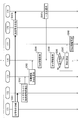
図8は、時刻同期の全体処理を示すシーケンス図である。このシーケンス図は大きく3つの処理ブロックに分類される。
(1)待ちあわせ遅延Wms、Wsmを決定するための前準備処理(S30=詳細はS31~S36)。
(2)下りのPTPパケットを待ちあわせ遅延Wmsだけ待ち合わせることで、伝搬遅延Dmaxとしてスレーブノード4に通知する処理(S10=詳細はS11~S14)。
(3)上りのPTPパケットを待ちあわせ遅延Wsmだけ待ち合わせることで、伝搬遅延Dmaxとしてマスタノード3に通知する処理(S20=詳細はS21~S24)。
(1)待ちあわせ遅延Wms、Wsmを決定するための前準備処理(S30=詳細はS31~S36)。
(2)下りのPTPパケットを待ちあわせ遅延Wmsだけ待ち合わせることで、伝搬遅延Dmaxとしてスレーブノード4に通知する処理(S10=詳細はS11~S14)。
(3)上りのPTPパケットを待ちあわせ遅延Wsmだけ待ち合わせることで、伝搬遅延Dmaxとしてマスタノード3に通知する処理(S20=詳細はS21~S24)。
なお、図2で説明したように、伝搬遅延Dmaxは、実際の測定された伝搬遅延Dms、Dsmなどの遅延量に対して、余裕を持って設定される。よって、伝搬遅延Dms、Dsmの測定値はネットワークの混雑状況によって時々刻々と変化するものの、(1)の前準備処理(S30)は基本的に1回測定すればよい。一方、ネットワークの増設などの大幅なネットワーク設備更新が発生したときには、遅延量も大きく変動するため、前準備処理(S30)を再度実行することが好ましい。
まず、伝搬遅延Dms、Dsmの情報収集を行うための前準備処理(S30)を説明する。
S31として、第1伝送装置1は、図9で後記する送信側の処理を行うことで、伝搬遅延Dmsを求めるための独自パケットを第2伝送装置2に送信する。
S32として、第2伝送装置2は、図10で後記する受信側の処理を行うことで、伝搬遅延Dmsを求める。
S33として、第2伝送装置2は、図11で後記する送信側の処理を行うことで、伝搬遅延Dsmを求めるための独自パケットを第1伝送装置1に送信する。
S34として、第1伝送装置1は、図12で後記する受信側の処理を行うことで、伝搬遅延Dsmを求める。
なお、S33の独自パケットには、S32で求めた伝搬遅延Dmsも含まれる。これにより、S34の時点で、第1同期用モジュール10は、自身で求めた伝搬遅延Dsmに加えて、通知された伝搬遅延Dmsも取得することができる。
S31として、第1伝送装置1は、図9で後記する送信側の処理を行うことで、伝搬遅延Dmsを求めるための独自パケットを第2伝送装置2に送信する。
S32として、第2伝送装置2は、図10で後記する受信側の処理を行うことで、伝搬遅延Dmsを求める。
S33として、第2伝送装置2は、図11で後記する送信側の処理を行うことで、伝搬遅延Dsmを求めるための独自パケットを第1伝送装置1に送信する。
S34として、第1伝送装置1は、図12で後記する受信側の処理を行うことで、伝搬遅延Dsmを求める。
なお、S33の独自パケットには、S32で求めた伝搬遅延Dmsも含まれる。これにより、S34の時点で、第1同期用モジュール10は、自身で求めた伝搬遅延Dsmに加えて、通知された伝搬遅延Dmsも取得することができる。
S35として、第1伝送装置1は、図13で後記する送信側の処理を行うことで、伝搬遅延Dms、Dsmから伝搬遅延Dmaxを求める。これにより、待ちあわせ遅延Wsmを自身の可変遅延部178に設定できる。そして、第1伝送装置1は、求めた伝搬遅延Dmaxを含めた独自パケットを第2伝送装置2に送信する。
S36として、第2伝送装置2は、図14で後記する受信側の処理を行うことで、通知された伝搬遅延Dmaxから待ちあわせ遅延Wmsを求め、その待ちあわせ遅延Wmsを自身の可変遅延部178に設定できる。
S36として、第2伝送装置2は、図14で後記する受信側の処理を行うことで、通知された伝搬遅延Dmaxから待ちあわせ遅延Wmsを求め、その待ちあわせ遅延Wmsを自身の可変遅延部178に設定できる。
次に、(2)下りのPTPパケットの通知処理(S10)を説明する。下りのPTPパケットとは、発着時刻の計測対象となる下りのSyncメッセージ(図18のS11z)である。なお、発着時刻の計測対象とならない下りのFollow-upメッセージ(S12z)と、下りのDelay_Responseメッセージ(S14z)とについては、通知処理(S10)の対象としてもよいし(待ち合わせを行う)、対象外としてもよい(待ち合わせを行わないで従来のPTP処理を行う)。
S11として、マスタノード3は、下りのPTPパケットをスレーブノード4に向けて送信し、PTPパケットを中継先の第1伝送装置1が受信する。
S12として、第1伝送装置1は、図15で後記する送信側処理を行い、下りのPTPパケットを第2伝送装置2に転送する。
S13として、第2伝送装置2は、図16で後記する受信側処理を行うことで、下りのPTPパケットを待ち合わせる。
S14として、第2伝送装置2は、下りのPTPパケットをスレーブノード4に転送する。
S11として、マスタノード3は、下りのPTPパケットをスレーブノード4に向けて送信し、PTPパケットを中継先の第1伝送装置1が受信する。
S12として、第1伝送装置1は、図15で後記する送信側処理を行い、下りのPTPパケットを第2伝送装置2に転送する。
S13として、第2伝送装置2は、図16で後記する受信側処理を行うことで、下りのPTPパケットを待ち合わせる。
S14として、第2伝送装置2は、下りのPTPパケットをスレーブノード4に転送する。
そして、(3)上りのPTPパケットの通知処理(S20)を説明する。上りのPTPパケットとは、発着時刻の計測対象となる上りのDelay_Requestメッセージ(図18のS13z)である。
通知処理(S20)は、通知処理(S10)とPTPパケットの送信方向を反転させ、S13で第2伝送装置2が待ちあわせ遅延Wmsだけ待ち合わせる処理を、S23で第1伝送装置1が待ちあわせ遅延Wsmだけ待ち合わせる処理に置き換えたものである。
S21として、スレーブノード4は、上りのPTPパケットをマスタノード3に向けて送信し、PTPパケットを中継先の第2伝送装置2が受信する。
S22として、第2伝送装置2は、図15と同様の送信側処理を行い、上りのPTPパケットを第1伝送装置1に転送する。
S23として、第1伝送装置1は、図16と同様の受信側処理を行うことで、上りのPTPパケットを待ち合わせる。
S24として、第1伝送装置1は、上りのPTPパケットをマスタノード3に転送する。
通知処理(S20)は、通知処理(S10)とPTPパケットの送信方向を反転させ、S13で第2伝送装置2が待ちあわせ遅延Wmsだけ待ち合わせる処理を、S23で第1伝送装置1が待ちあわせ遅延Wsmだけ待ち合わせる処理に置き換えたものである。
S21として、スレーブノード4は、上りのPTPパケットをマスタノード3に向けて送信し、PTPパケットを中継先の第2伝送装置2が受信する。
S22として、第2伝送装置2は、図15と同様の送信側処理を行い、上りのPTPパケットを第1伝送装置1に転送する。
S23として、第1伝送装置1は、図16と同様の受信側処理を行うことで、上りのPTPパケットを待ち合わせる。
S24として、第1伝送装置1は、上りのPTPパケットをマスタノード3に転送する。
S40として、スレーブノード4は、自身の時計について、時刻同期の補正処理を行う。具体的には、スレーブノード4は、図18で示したように、以下の数式1でオフセット値を求める。
オフセット値=((着時刻t2-発時刻t1)-(着時刻t4-発時刻t3))/2 …(数式1)
オフセット値=((着時刻t2-発時刻t1)-(着時刻t4-発時刻t3))/2 …(数式1)
以上、図8を参照して時刻同期の全体処理を説明した、以下、図9~図16を参照して、この全体処理の一部である部分処理の詳細を個別に説明する。
図9は、S31の送信側処理の詳細を示すシーケンス図である。このシーケンスは、第1伝送装置1内の第1同期用モジュール10によって実行される。
S311として、遅延管理部174は、遅延算出用パケットを独自パケットとして新規に生成し、コピー部161に出力する。
S312として、コピー部161は、遅延算出用パケットをコピーして、2波長分のキュー部162に出力する。
S313として、キュー部162によるバッファリング処理、トリガ付与部163によるトリガ付与処理がなされた遅延算出用パケットは、可変波長トランスミッタ164に出力される。
S314として、可変波長トランスミッタ164は、2波長分の遅延算出用パケットを光信号に変換し、その光信号を同時に第2同期用モジュール20に出力する。
S311として、遅延管理部174は、遅延算出用パケットを独自パケットとして新規に生成し、コピー部161に出力する。
S312として、コピー部161は、遅延算出用パケットをコピーして、2波長分のキュー部162に出力する。
S313として、キュー部162によるバッファリング処理、トリガ付与部163によるトリガ付与処理がなされた遅延算出用パケットは、可変波長トランスミッタ164に出力される。
S314として、可変波長トランスミッタ164は、2波長分の遅延算出用パケットを光信号に変換し、その光信号を同時に第2同期用モジュール20に出力する。
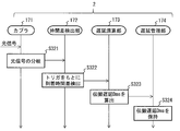
図10は、S32の受信側処理の詳細を示すシーケンス図である。このシーケンスは、第2伝送装置2内の第2同期用モジュール20によって実行される。
S321として、カプラ171は、受信した2波長分の光信号の分岐し、その一方を時間差検出部172に出力する。
S322として、時間差検出部172は、トリガ付与部163によるトリガをもとに光信号の到着時間差(△t12)を検出し、その結果を遅延演算部173に出力する。
S323として、遅延演算部173は、図7で示したように、光信号の到着時間差から伝搬遅延Dmsを算出し、その結果を遅延管理部174に出力する。
S324として、遅延管理部174は、伝搬遅延Dmsを保持する。
S321として、カプラ171は、受信した2波長分の光信号の分岐し、その一方を時間差検出部172に出力する。
S322として、時間差検出部172は、トリガ付与部163によるトリガをもとに光信号の到着時間差(△t12)を検出し、その結果を遅延演算部173に出力する。
S323として、遅延演算部173は、図7で示したように、光信号の到着時間差から伝搬遅延Dmsを算出し、その結果を遅延管理部174に出力する。
S324として、遅延管理部174は、伝搬遅延Dmsを保持する。
図11は、S33の送信側処理の詳細を示すシーケンス図である。このシーケンスは、第2伝送装置2内の第2同期用モジュール20によって実行される。
S331として、遅延管理部174は、遅延算出用パケットを独自パケットとして新規に生成し、コピー部161に出力する。なお、この遅延算出用パケットには、S324で保持された伝搬遅延Dmsが付加されている。
S332として、コピー部161は、遅延算出用パケットをコピーして、2波長分のキュー部162に出力する。
S333として、キュー部162によるバッファリング処理、トリガ付与部163によるトリガ付与処理がなされた遅延算出用パケットは、可変波長トランスミッタ164に出力される。
S334として、可変波長トランスミッタ164は、2波長分の遅延算出用パケットを光信号に変換し、その光信号を同時に第1同期用モジュール10に出力する。
S331として、遅延管理部174は、遅延算出用パケットを独自パケットとして新規に生成し、コピー部161に出力する。なお、この遅延算出用パケットには、S324で保持された伝搬遅延Dmsが付加されている。
S332として、コピー部161は、遅延算出用パケットをコピーして、2波長分のキュー部162に出力する。
S333として、キュー部162によるバッファリング処理、トリガ付与部163によるトリガ付与処理がなされた遅延算出用パケットは、可変波長トランスミッタ164に出力される。
S334として、可変波長トランスミッタ164は、2波長分の遅延算出用パケットを光信号に変換し、その光信号を同時に第1同期用モジュール10に出力する。
図12は、S34の受信側処理の詳細を示すシーケンス図である。このシーケンスは、第1伝送装置1内の第1同期用モジュール10によって実行される。
S341として、カプラ171は、2波長分の光信号を時間差検出部172、光受信部175に分岐して出力する。
S341bとして、光受信部175は、受信した光信号を識別セレクタ176に出力する。
S341cとして、識別セレクタ176は、2波長分の光信号から一方を選択して遅延管理部174に出力する。
S341として、カプラ171は、2波長分の光信号を時間差検出部172、光受信部175に分岐して出力する。
S341bとして、光受信部175は、受信した光信号を識別セレクタ176に出力する。
S341cとして、識別セレクタ176は、2波長分の光信号から一方を選択して遅延管理部174に出力する。
S342として、時間差検出部172は、トリガ付与部163によるトリガをもとに光信号の到着時間差(△t21)を検出し、その結果を遅延演算部173に出力する。
S343として、遅延演算部173は、図7で示したように、光信号の到着時間差から伝搬遅延Dsmを算出し、その結果を遅延管理部174に出力する。
S344として、遅延管理部174は、S343の伝搬遅延Dsmの情報を保持する。
S345として、遅延管理部174は、S341cから通知された独自パケットから読み出した伝搬遅延Dmsの情報を保持する。
S346として、遅延管理部174は、伝搬遅延Dms、Dsmの両方を保持したか否かを判定する。両方を保持していない場合(No)は処理を終了し、両方を保持している場合(Yes)には処理をS347に進める。
S347として、遅延管理部174は、図2で示したように、伝搬遅延Dms、Dsmのうちの最大値よりもさらに大きい伝搬遅延Dmaxを決定し、その結果を遅延量制御部177に出力する。
S348として、遅延量制御部177は、伝搬遅延Dmaxの情報を保持する。
S343として、遅延演算部173は、図7で示したように、光信号の到着時間差から伝搬遅延Dsmを算出し、その結果を遅延管理部174に出力する。
S344として、遅延管理部174は、S343の伝搬遅延Dsmの情報を保持する。
S345として、遅延管理部174は、S341cから通知された独自パケットから読み出した伝搬遅延Dmsの情報を保持する。
S346として、遅延管理部174は、伝搬遅延Dms、Dsmの両方を保持したか否かを判定する。両方を保持していない場合(No)は処理を終了し、両方を保持している場合(Yes)には処理をS347に進める。
S347として、遅延管理部174は、図2で示したように、伝搬遅延Dms、Dsmのうちの最大値よりもさらに大きい伝搬遅延Dmaxを決定し、その結果を遅延量制御部177に出力する。
S348として、遅延量制御部177は、伝搬遅延Dmaxの情報を保持する。
図13は、S35の送信側処理の詳細を示すシーケンス図である。このシーケンスは、第1伝送装置1内の第1同期用モジュール10によって実行される。
S351として、遅延管理部174は、伝搬遅延Dmax通知用パケットを独自パケットとして新規に生成し、コピー部161に出力する。
S352として、コピー部161は、伝搬遅延Dmax通知用パケットをコピーして、2波長分のキュー部162に出力する。
S353として、キュー部162によるバッファリング処理、トリガ付与部163によるトリガ付与処理がなされた伝搬遅延Dmax通知用パケットは、可変波長トランスミッタ164に出力される。
S354として、可変波長トランスミッタ164は、2波長分の伝搬遅延Dmax通知用パケットを光信号に変換し、その光信号を同時に第2同期用モジュール20に出力する。
S351として、遅延管理部174は、伝搬遅延Dmax通知用パケットを独自パケットとして新規に生成し、コピー部161に出力する。
S352として、コピー部161は、伝搬遅延Dmax通知用パケットをコピーして、2波長分のキュー部162に出力する。
S353として、キュー部162によるバッファリング処理、トリガ付与部163によるトリガ付与処理がなされた伝搬遅延Dmax通知用パケットは、可変波長トランスミッタ164に出力される。
S354として、可変波長トランスミッタ164は、2波長分の伝搬遅延Dmax通知用パケットを光信号に変換し、その光信号を同時に第2同期用モジュール20に出力する。
図14は、S36の受信側処理の詳細を示すシーケンス図である。このシーケンスは、第2伝送装置2内の第2同期用モジュール20によって実行される。
S361として、カプラ171は、2波長分の光信号を時間差検出部172、光受信部175に分岐して出力する。しかし、今回は伝搬遅延Dmax通知用パケットに対して伝搬遅延の測定は行わないので、時間差検出部172の側では出力された光信号を破棄する。
S362として、光受信部175は、受信した光信号を識別セレクタ176に出力する。
S363として、識別セレクタ176は、2波長分の光信号から一方の伝搬遅延Dmax通知用パケットを選択して遅延管理部174に出力する。
S364として、遅延管理部174は、伝搬遅延Dmax通知用パケットから読み出した伝搬遅延Dmaxの情報を保持するとともに、その結果を遅延量制御部177に出力する。
S365として、遅延量制御部177は、伝搬遅延Dmaxの情報を保持する。
S361として、カプラ171は、2波長分の光信号を時間差検出部172、光受信部175に分岐して出力する。しかし、今回は伝搬遅延Dmax通知用パケットに対して伝搬遅延の測定は行わないので、時間差検出部172の側では出力された光信号を破棄する。
S362として、光受信部175は、受信した光信号を識別セレクタ176に出力する。
S363として、識別セレクタ176は、2波長分の光信号から一方の伝搬遅延Dmax通知用パケットを選択して遅延管理部174に出力する。
S364として、遅延管理部174は、伝搬遅延Dmax通知用パケットから読み出した伝搬遅延Dmaxの情報を保持するとともに、その結果を遅延量制御部177に出力する。
S365として、遅延量制御部177は、伝搬遅延Dmaxの情報を保持する。
図15は、S12の送信側処理の詳細を示すシーケンス図である。このシーケンスは、第1伝送装置1内の第1同期用モジュール10によって実行される。
S121として、遅延管理部174は、PTPパケット受信時の共通部19により行われる各種処理(O/E・E/O部11の処理、PHY部12の処理、MAC部13の処理)を行い、その結果をコピー部161に出力する。
S122として、コピー部161は、PTPパケットをコピーして、2波長分のキュー部162に出力する。
S123として、キュー部162によるバッファリング処理、トリガ付与部163によるトリガ付与処理がなされたPTPパケットは、可変波長トランスミッタ164に出力される。
S124として、可変波長トランスミッタ164は、2波長分のPTPパケットを光信号に変換し、その光信号を同時に第2同期用モジュール20に出力する。
S121として、遅延管理部174は、PTPパケット受信時の共通部19により行われる各種処理(O/E・E/O部11の処理、PHY部12の処理、MAC部13の処理)を行い、その結果をコピー部161に出力する。
S122として、コピー部161は、PTPパケットをコピーして、2波長分のキュー部162に出力する。
S123として、キュー部162によるバッファリング処理、トリガ付与部163によるトリガ付与処理がなされたPTPパケットは、可変波長トランスミッタ164に出力される。
S124として、可変波長トランスミッタ164は、2波長分のPTPパケットを光信号に変換し、その光信号を同時に第2同期用モジュール20に出力する。
図16は、S13の受信側処理の詳細を示すシーケンス図である。このシーケンスは、第2伝送装置2内の第2同期用モジュール20によって実行される。
S131として、カプラ171は、2波長分の光信号を時間差検出部172、光受信部175に分岐して出力する。
S131bとして、光受信部175は、受信した光信号を識別セレクタ176に出力する。
S131cとして、識別セレクタ176は、2波長分の光信号から一方のPTPパケットを選択して可変遅延部178に待ち合わせ対象として出力する。
S131として、カプラ171は、2波長分の光信号を時間差検出部172、光受信部175に分岐して出力する。
S131bとして、光受信部175は、受信した光信号を識別セレクタ176に出力する。
S131cとして、識別セレクタ176は、2波長分の光信号から一方のPTPパケットを選択して可変遅延部178に待ち合わせ対象として出力する。
S132として、時間差検出部172は、トリガ付与部163によるトリガをもとに光信号の到着時間差(△t12)を検出し、その結果を遅延演算部173に出力する。
S133として、遅延演算部173は、図7で示したように、光信号の到着時間差から伝搬遅延Dmsを算出し、その結果を遅延管理部174を介して遅延量制御部177に出力する。
S134として、遅延管理部174は、図2で示したように、「伝搬遅延Dmax-伝搬遅延Dms=待ちあわせ遅延Wms」を算出し、その結果を可変遅延部178に出力する。
S135として、可変遅延部178は、S131cのPTPパケットを待ちあわせ遅延Wmsだけ遅延させてから共通部19に出力する。
S136として、共通部19は、PTPパケット送信時の各種処理(MAC部13の処理、PHY部12の処理、O/E・E/O部11の処理)を行ってから、S14のPTPパケット送信処理を行う。
S133として、遅延演算部173は、図7で示したように、光信号の到着時間差から伝搬遅延Dmsを算出し、その結果を遅延管理部174を介して遅延量制御部177に出力する。
S134として、遅延管理部174は、図2で示したように、「伝搬遅延Dmax-伝搬遅延Dms=待ちあわせ遅延Wms」を算出し、その結果を可変遅延部178に出力する。
S135として、可変遅延部178は、S131cのPTPパケットを待ちあわせ遅延Wmsだけ遅延させてから共通部19に出力する。
S136として、共通部19は、PTPパケット送信時の各種処理(MAC部13の処理、PHY部12の処理、O/E・E/O部11の処理)を行ってから、S14のPTPパケット送信処理を行う。
以上説明した本実施形態の時刻伝送システムは、マスタノード3、スレーブノード4間に発生してしまう遅延非対称性を、その中継地点に位置する伝送装置(第1伝送装置1、第2伝送装置2)により補正(吸収)することを主な特徴とする。
つまり、PTPパケットの経路終点に近い伝送装置において、待ちあわせ遅延Wms、Wsmを恣意的に発生させることで、双方向の伝搬遅延がともにDmaxになるように(対称になるように)補正している。この伝搬遅延Dmaxを求めるために、伝送装置に備えられる第1同期用モジュール10、第2同期用モジュール20間で2波長分の独自パケットを事前に送受信し、その独自パケットの到着時間差から同期用モジュール間の伝搬遅延Dms、Dsmを高精度に求める構成とした。
つまり、PTPパケットの経路終点に近い伝送装置において、待ちあわせ遅延Wms、Wsmを恣意的に発生させることで、双方向の伝搬遅延がともにDmaxになるように(対称になるように)補正している。この伝搬遅延Dmaxを求めるために、伝送装置に備えられる第1同期用モジュール10、第2同期用モジュール20間で2波長分の独自パケットを事前に送受信し、その独自パケットの到着時間差から同期用モジュール間の伝搬遅延Dms、Dsmを高精度に求める構成とした。
これにより、時刻同期プロトコルであるPTPの誤差要因(遅延非対称性)を除去することができ、地理的に離れた拠点間の高精度な時刻同期が可能になる。
さらに、(a)伝送経路途中の装置内遅延と、(b)伝送路の遅延とを含む伝搬遅延Dms、Dsmが高精度に測定され、その測定結果をもとに伝搬遅延Dmaxが第1同期用モジュール10、第2同期用モジュール20に設定される(図2参照)。これにより、伝搬遅延Dmaxとして過剰に大きい値が設定されてしまうことでPTPパケットを余分に待たせたり、伝搬遅延Dmaxとして過剰に小さい値が設定されてしまうことでPTPパケットの遅延非対称性を除去しきれなかったりする不都合を予防できる。
さらに、(a)伝送経路途中の装置内遅延と、(b)伝送路の遅延とを含む伝搬遅延Dms、Dsmが高精度に測定され、その測定結果をもとに伝搬遅延Dmaxが第1同期用モジュール10、第2同期用モジュール20に設定される(図2参照)。これにより、伝搬遅延Dmaxとして過剰に大きい値が設定されてしまうことでPTPパケットを余分に待たせたり、伝搬遅延Dmaxとして過剰に小さい値が設定されてしまうことでPTPパケットの遅延非対称性を除去しきれなかったりする不都合を予防できる。
なお、第1同期用モジュール10、第2同期用モジュール20のうちの制御部を動作させるプログラムは、通信回線を介して配布したり、CD-ROM等の記録媒体に記録して配布したりすることも可能である。
1 第1伝送装置
2 第2伝送装置
3 マスタノード(第1時刻同期装置)
4 スレーブノード(第2時刻同期装置)
10 第1同期用モジュール
11 O/E・E/O部
12 PHY部
13 MAC部
14 クロックタイマ
15 環境情報管理部
16 送信部
17 受信部
19 共通部
20 第2同期用モジュール
161,165 コピー部
162 キュー部
163 トリガ付与部
164 可変波長トランスミッタ
171 カプラ
172 時間差検出部
173 遅延演算部
174 遅延管理部
175 光受信部
176 識別セレクタ
177 遅延量制御部
178 可変遅延部
2 第2伝送装置
3 マスタノード(第1時刻同期装置)
4 スレーブノード(第2時刻同期装置)
10 第1同期用モジュール
11 O/E・E/O部
12 PHY部
13 MAC部
14 クロックタイマ
15 環境情報管理部
16 送信部
17 受信部
19 共通部
20 第2同期用モジュール
161,165 コピー部
162 キュー部
163 トリガ付与部
164 可変波長トランスミッタ
171 カプラ
172 時間差検出部
173 遅延演算部
174 遅延管理部
175 光受信部
176 識別セレクタ
177 遅延量制御部
178 可変遅延部
Claims (3)
- 第1時刻同期装置側に接続される第1伝送装置と、前記第1伝送装置に対向し第2時刻同期装置側に接続される第2伝送装置を経由して、前記第1時刻同期装置と前記第2時刻同期装置との間で時刻同期用パケットを送受信し、その送受信の時刻情報をもとに前記第2時刻同期装置の時刻を同期する時刻伝送システムに用いられる伝送装置であって、
前記第1伝送装置および前記第2伝送装置としてそれぞれ動作する伝送装置は、
複数波長分の遅延算出用パケットを同時に対向の伝送装置に送信する送信部と、
前記対向の伝送装置から受信した複数波長分の前記遅延算出用パケットの到着した時刻の差をもとに、前記対向の伝送装置から自装置までの第1伝搬遅延を求め、前記対向の伝送装置が求めた自装置から前記対向の伝送装置までの第2伝搬遅延の通知を受け、前記第1伝搬遅延および前記第2伝搬遅延よりも大きな設定遅延を求める受信部とを有し、
前記受信部は、
前記対向の伝送装置から複数波長分の前記時刻同期用パケットを受信すると、それらの前記時刻同期用パケットの到着した時刻の差をもとに、前記対向の伝送装置から自装置までの第3伝搬遅延を求め、
受信した前記時刻同期用パケットに対して、前記第3伝搬遅延から前記設定遅延までの待ちあわせ遅延を発生させた後に、自装置側に接続される時刻同期装置に送信することを特徴とする
伝送装置。 - 請求項1に記載の伝送装置と、前記第1時刻同期装置と、前記第2時刻同期装置とを含めて構成される時刻伝送システムであって、
前記第2時刻同期装置は、前記時刻同期用パケットの前記時刻同期装置間における発時刻および着時刻を用いて前記第2時刻同期装置の時計のずれであるオフセット値を計算することを特徴とする
時刻伝送システム。 - 第1時刻同期装置側に接続される第1伝送装置と、前記第1伝送装置に対向し第2時刻同期装置側に接続される第2伝送装置を経由して、前記第1時刻同期装置と前記第2時刻同期装置との間で時刻同期用パケットを送受信し、その送受信の時刻情報をもとに前記第2時刻同期装置の時刻を同期する時刻伝送システムが実行する遅延補正方法であって、
前記第1伝送装置および前記第2伝送装置としてそれぞれ動作する伝送装置は、
複数波長分の遅延算出用パケットを同時に対向の伝送装置に送信する送信部と、
前記対向の伝送装置から受信した複数波長分の前記遅延算出用パケットの到着した時刻の差をもとに、前記対向の伝送装置から自装置までの第1伝搬遅延を求め、前記対向の伝送装置が求めた自装置から前記対向の伝送装置までの第2伝搬遅延の通知を受け、前記第1伝搬遅延および前記第2伝搬遅延よりも大きな設定遅延を求める受信部とを有し、
前記受信部は、
前記対向の伝送装置から複数波長分の前記時刻同期用パケットを受信すると、それらの前記時刻同期用パケットの到着した時刻の差をもとに、前記対向の伝送装置から自装置までの第3伝搬遅延を求め、
受信した前記時刻同期用パケットに対して、前記第3伝搬遅延から前記設定遅延までの待ちあわせ遅延を発生させた後に、自装置側に接続される時刻同期装置に送信することを特徴とする
遅延補正方法。
Priority Applications (1)
| Application Number | Priority Date | Filing Date | Title |
|---|---|---|---|
| US17/429,172 US11791922B2 (en) | 2019-02-14 | 2020-02-06 | Transmission device, time transmission system, and delay compensation method |
Applications Claiming Priority (2)
| Application Number | Priority Date | Filing Date | Title |
|---|---|---|---|
| JP2019-024802 | 2019-02-14 | ||
| JP2019024802A JP7310163B2 (ja) | 2019-02-14 | 2019-02-14 | 伝送装置、時刻伝送システム、および、遅延補正方法 |
Publications (1)
| Publication Number | Publication Date |
|---|---|
| WO2020166485A1 true WO2020166485A1 (ja) | 2020-08-20 |
Family
ID=72045402
Family Applications (1)
| Application Number | Title | Priority Date | Filing Date |
|---|---|---|---|
| PCT/JP2020/004618 Ceased WO2020166485A1 (ja) | 2019-02-14 | 2020-02-06 | 伝送装置、時刻伝送システム、および、遅延補正方法 |
Country Status (3)
| Country | Link |
|---|---|
| US (1) | US11791922B2 (ja) |
| JP (1) | JP7310163B2 (ja) |
| WO (1) | WO2020166485A1 (ja) |
Families Citing this family (3)
| Publication number | Priority date | Publication date | Assignee | Title |
|---|---|---|---|---|
| US20240255898A1 (en) * | 2021-05-19 | 2024-08-01 | Nippon Telegraph And Telephone Corporation | Measuring device, measuring method, and time synchronization system |
| CN116471211B (zh) * | 2023-06-19 | 2023-10-13 | 威胜信息技术股份有限公司 | 一种电力物联网精准对时方法 |
| CN117687347B (zh) * | 2024-02-02 | 2024-04-09 | 三峡智控科技有限公司 | 一种基于fpga和通信网络的同步录波方法及装置 |
Citations (3)
| Publication number | Priority date | Publication date | Assignee | Title |
|---|---|---|---|---|
| JP2014216669A (ja) * | 2013-04-22 | 2014-11-17 | 日本電信電話株式会社 | 通信システム、同期システム、通信方法 |
| JP2015065525A (ja) * | 2013-09-24 | 2015-04-09 | 株式会社日立製作所 | 通信システム及び時刻同期方法 |
| US20150104167A1 (en) * | 2012-05-16 | 2015-04-16 | Telefonaktiebolaget L M Ericsson (Publ) | Determining properties of an optical communications path in an optical communications network |
Family Cites Families (6)
| Publication number | Priority date | Publication date | Assignee | Title |
|---|---|---|---|---|
| FR2965131B1 (fr) * | 2010-09-20 | 2012-09-28 | Alcatel Lucent | Procede de correction d'une asymetrie de delai. |
| US9166681B2 (en) * | 2010-10-13 | 2015-10-20 | Telefonaktiebolaget L M Ericsson (Publ) | Determining asymmetries in a communication network |
| US10075258B2 (en) * | 2012-08-22 | 2018-09-11 | Telefonaktiebolaget Lm Ericsson (Publ) | Distributing path delay data in a connection-oriented communications network |
| WO2014107717A1 (en) * | 2013-01-07 | 2014-07-10 | Microsemi Frequency And Time Corporation | Universal asymmetry correction for packet timing protocols |
| JP5933147B2 (ja) * | 2014-05-23 | 2016-06-08 | 三菱電機株式会社 | 通信装置及び通信方法及びプログラム |
| BR112017003510A2 (pt) * | 2014-09-10 | 2017-12-05 | Siemens Ag | método para determinar um atraso de propagação de uma mensagem, e, componente de rede. |
-
2019
- 2019-02-14 JP JP2019024802A patent/JP7310163B2/ja active Active
-
2020
- 2020-02-06 US US17/429,172 patent/US11791922B2/en active Active
- 2020-02-06 WO PCT/JP2020/004618 patent/WO2020166485A1/ja not_active Ceased
Patent Citations (3)
| Publication number | Priority date | Publication date | Assignee | Title |
|---|---|---|---|---|
| US20150104167A1 (en) * | 2012-05-16 | 2015-04-16 | Telefonaktiebolaget L M Ericsson (Publ) | Determining properties of an optical communications path in an optical communications network |
| JP2014216669A (ja) * | 2013-04-22 | 2014-11-17 | 日本電信電話株式会社 | 通信システム、同期システム、通信方法 |
| JP2015065525A (ja) * | 2013-09-24 | 2015-04-09 | 株式会社日立製作所 | 通信システム及び時刻同期方法 |
Also Published As
| Publication number | Publication date |
|---|---|
| JP7310163B2 (ja) | 2023-07-19 |
| JP2020134203A (ja) | 2020-08-31 |
| US11791922B2 (en) | 2023-10-17 |
| US20220103281A1 (en) | 2022-03-31 |
Similar Documents
| Publication | Publication Date | Title |
|---|---|---|
| US9705770B2 (en) | Determining asymmetries in a communication network | |
| US9584217B2 (en) | Determining properties of an optical communications path in an optical communications network | |
| US10341083B2 (en) | System and methods for network synchronization | |
| US8600239B2 (en) | Precise clock synchronization over optical fiber | |
| KR101479483B1 (ko) | 지연의 비대칭을 보정하는 방법 | |
| US9172525B2 (en) | Method and device for compensating for time path | |
| US11750358B2 (en) | Time transmission device and transmission method | |
| JP7491665B2 (ja) | 時刻伝送補正装置、時刻伝送システム、および、遅延測定方法 | |
| CN105723638A (zh) | 用于检测受通信网中的节点之间的路径延迟不对称性中的改变所影响的定时参考的方法 | |
| WO2009118878A1 (ja) | Ponシステム | |
| JP7310163B2 (ja) | 伝送装置、時刻伝送システム、および、遅延補正方法 | |
| WO2020166484A1 (ja) | 伝送装置、時刻伝送システム、および、遅延補正方法 | |
| JP7200636B2 (ja) | 伝送装置、時刻伝送システム、および、遅延測定方法 | |
| JP6456787B2 (ja) | 時刻同期装置および時刻同期方法 | |
| EP1213862A1 (en) | Optical data network with protection switching |
Legal Events
| Date | Code | Title | Description |
|---|---|---|---|
| 121 | Ep: the epo has been informed by wipo that ep was designated in this application |
Ref document number: 20755107 Country of ref document: EP Kind code of ref document: A1 |
|
| NENP | Non-entry into the national phase |
Ref country code: DE |
|
| 122 | Ep: pct application non-entry in european phase |
Ref document number: 20755107 Country of ref document: EP Kind code of ref document: A1 |