WO2020166332A1 - ワーク加熱装置 - Google Patents
ワーク加熱装置 Download PDFInfo
- Publication number
- WO2020166332A1 WO2020166332A1 PCT/JP2020/003119 JP2020003119W WO2020166332A1 WO 2020166332 A1 WO2020166332 A1 WO 2020166332A1 JP 2020003119 W JP2020003119 W JP 2020003119W WO 2020166332 A1 WO2020166332 A1 WO 2020166332A1
- Authority
- WO
- WIPO (PCT)
- Prior art keywords
- temperature
- target value
- appearance
- heat
- unit
- Prior art date
- Legal status (The legal status is an assumption and is not a legal conclusion. Google has not performed a legal analysis and makes no representation as to the accuracy of the status listed.)
- Ceased
Links
Images

Classifications
-
- B—PERFORMING OPERATIONS; TRANSPORTING
- B65—CONVEYING; PACKING; STORING; HANDLING THIN OR FILAMENTARY MATERIAL
- B65B—MACHINES, APPARATUS OR DEVICES FOR, OR METHODS OF, PACKAGING ARTICLES OR MATERIALS; UNPACKING
- B65B51/00—Devices for, or methods of, sealing or securing package folds or closures; Devices for gathering or twisting wrappers, or necks of bags
- B65B51/10—Applying or generating heat or pressure or combinations thereof
-
- B—PERFORMING OPERATIONS; TRANSPORTING
- B65—CONVEYING; PACKING; STORING; HANDLING THIN OR FILAMENTARY MATERIAL
- B65B—MACHINES, APPARATUS OR DEVICES FOR, OR METHODS OF, PACKAGING ARTICLES OR MATERIALS; UNPACKING
- B65B57/00—Automatic control, checking, warning, or safety devices
Definitions
- the present invention relates to a work heating device that heat-welds a work such as a packaging material.
- a work heating device that heat-welds a work such as a packaging material.
- it relates to a temperature control technique of a heat seal portion for heat welding.
- the conditions under which abnormalities did not occur in the heat-welded part of the workpiece were determined by visual inspection through trial and error.
- the conditions in this case are heat treatment conditions such as a temperature target value for heat welding and a heat treatment time. Also, during actual production, the heat treatment conditions were fixed and used.
- a temperature control method of an impulse seal device in which a non-contact thermometer is provided and the energization time or conduction angle to the heater wire is controlled based on the detection signal of the non-contact thermometer (for example, Patent Document 1). reference.).
- an object of the present invention is to provide a work heating device capable of coping with changes in the lot of works and changes in environmental conditions such as ambient temperature.
- the work heating device includes a heat seal part that heats and heat-welds a work, An appearance evaluation unit for evaluating the appearance of the heat-welded portion of the work, Based on the appearance evaluation by the appearance evaluation unit, a temperature target value correction unit that corrects the temperature target value of the heat seal unit, Equipped with.
- the appearance of the heat-welded portion of the work is evaluated by the appearance evaluation unit, and feedback is provided to the heat seal unit based on the appearance evaluation. It can respond to changes in environmental conditions.
- FIG. 3 is a block diagram showing a configuration of a work heating device according to the first embodiment. It is a block diagram which shows the internal structure of the external appearance evaluation part of FIG. It is a block diagram which shows the physical structure and functional structure of the external appearance evaluation part of FIG.
- FIG. 3 is a schematic diagram showing an example of an appearance of a heat bar of the work heating device according to the first embodiment.
- FIG. 5 is a schematic diagram showing a heat bar and a temperature sensor of the work heating device of FIG. 4.
- FIG. 5 is a schematic diagram showing the relationship between the temperature of the heat bar, the temperature of the work, and the sealing operation of FIG. 4.
- FIG. 6 is a schematic diagram showing a relationship between a temperature target value and occurrence of appearance defects.
- 3 is a flowchart of a work heat welding method according to the first embodiment.
- a work heating device includes a heat seal portion that heats and heat-welds a work, An appearance evaluation unit for evaluating the appearance of the heat-welded portion of the work, Based on the appearance evaluation by the appearance evaluation unit, a temperature target value correction unit that corrects the temperature target value of the heat seal unit, Equipped with.
- the appearance evaluation unit is An image pickup unit for acquiring image data of the appearance of the heat-welded portion of the work; Regarding the image data of the appearance of the heat-welded portion of the work, an appearance defect detection unit that detects an appearance defect, Equipped with The temperature target value correction unit may correct the temperature target value of the heat seal unit based on the appearance defect detected by the appearance defect detection unit.
- the heat seal portion is With a heater, A temperature sensor for measuring the temperature of the heater, Based on the temperature measured by the temperature sensor, a heater temperature control unit for controlling the temperature of the heater to approach a temperature target value, May be provided.
- the heater temperature control unit corrects the temperature target value input in advance, and the corrected target temperature value is corrected by the temperature target value correction unit.
- the temperature of the heater may be controlled to approach the corrected target temperature value.
- the appearance evaluation unit detects an appearance defect
- the temperature target value correction unit corrects the temperature target value, and then the temperature sensor is used. It is judged whether or not the measured temperature is stable, and if the temperature is not stable, the corrected target temperature value need not be corrected again.
- the appearance evaluation unit detects an appearance defect
- the temperature target value correction unit corrects the temperature target value.
- the temperature target value after correction may not be corrected again within a predetermined time thereafter.
- the appearance evaluation unit detects an appearance defect
- the temperature target value correction unit corrects the temperature target value.
- the previously input temperature target value may be replaced with the corrected temperature target value and stored.
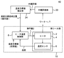
- FIG. 1 is a block diagram showing the configuration of the work heating device 40 according to the first embodiment.
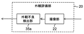
- FIG. 2 is a block diagram showing an internal configuration of the appearance evaluation unit 20 of FIG.
- FIG. 3 is a block diagram showing a physical configuration and a functional configuration of the appearance evaluation unit 20 of FIG.
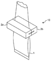
- FIG. 4 is a schematic diagram showing an example of the appearance of the heat bars 2a and 2b of the work heating device according to the first embodiment.
- the work heating device 40 according to the first embodiment includes a heat seal unit 10, an appearance evaluation unit 20, and a temperature target value correction unit 24.
- the work 1 is heated by the heat seal portion 10 and heat-welded.
- the appearance evaluation unit 20 evaluates the appearance of the heat-welded portion of the work 1.
- the temperature target value correction unit 24 corrects the temperature target value of the heat seal unit 10 based on the appearance evaluation by the appearance evaluation unit 20.
- the appearance evaluation unit 20 evaluates the appearance of the heat-welded portion of the work 1 and feeds it back to the heat seal unit 10 based on the appearance evaluation. It can also handle changes in environmental conditions such as temperature.
- the members constituting the work heating device 40 will be described below.
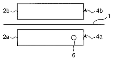
- FIG. 5 is a schematic view showing the heat bars 2a and 2b and the temperature sensor 6 of the work heating device of FIG.
- the heat seal unit 10 includes a heat bar 2 and a heater temperature control unit 8.
- the heat bars 2, 2a, 2b are, for example, sandwiching and heating the work 1 to heat-weld it.
- the two heat bars 2a and 2b are provided so as to sandwich the work 1, but the present invention is not limited to this, and one heat bar may be used.
- the work 1 has a continuous bag shape and is heat-welded at predetermined intervals by the heat bars 2a and 2b. As shown in FIGS.
- the heat bar 2 includes heaters 4, 4a, 4b and a temperature sensor 6 that measures the temperature of the heaters 4, 4a, 4b.
- the heaters 4a and 4b may be provided on each of the two heat bars 2a and 2b as shown in FIG. 5, or may be provided on only one of the heat bars.
- the temperature sensor 6 is provided at a position apart from the work 1 by a predetermined distance, the temperature sensor 6 is not limited to this, and may be provided close to the work 1.
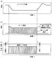
- FIG. 6 is a schematic diagram showing the relationship between the temperature of the heat bar of FIG. 4, the temperature of the work 1 and the sealing operation.
- FIG. 6A is a diagram showing the temperature of the heat bar during the continuous sealing operation.
- FIG. 6B is a diagram showing the temperature of the work during the continuous sealing operation.
- FIG. 6C is a schematic diagram showing the operation and the stop during the continuous sealing operation.
- the heat bars 2, 2a, 2b are temperature-controlled so as to approach the temperature target value for heat welding the work 1.
- the temperature of the heat bar is somewhat lowered because the contact with the work is started at the start of the continuous sealing operation, and during the continuous sealing operation, the steady heat conduction to the work is continuously performed and the steady heat conduction is in an equilibrium state. It stabilizes the temperature.
- the continuous sealing of the work is performed, for example, in 0.1 second to 2 seconds. With the end of continuous sealing, the temperature of the heat bar returns to a temperature close to the target temperature.
- the heater temperature control unit 8 controls the temperature of the heater 4 so as to approach the temperature target value based on the temperature measured by the temperature sensor 6.
- the heater temperature control unit 8 controls the heater 4 with the manipulated variable 2 such as a current value or a voltage value.
- the heater temperature control unit 8 has a temperature target value which is an initial value input in advance. As will be described later, this temperature target value replaces the initial temperature target value by the temperature target value correction amount from the temperature target value correction unit or the manipulated variable 1 of the corrected temperature target value itself. After that, the heater temperature control unit 8 successively replaces the temperature target value with the manipulated variable 1 of the temperature target value correction amount from the temperature target value correction unit.
- the initial temperature target value stored in the heater temperature control unit 8 may be replaced with the corrected target temperature value and stored, or the initial temperature target value may be held. Good.
- the corrected temperature target value is replaced and stored, the temperature target value in which the appearance defect occurs even once is updated, so that the appearance defect can be prevented from occurring again.
- the initial temperature target value may be held and the initial temperature target value may be read again at the time of a new operation. In this case, it is possible to appropriately cope with different lot variations and variations in environmental conditions such as ambient temperature.
- FIG. 3 is a block diagram showing a physical configuration and a functional configuration of the appearance evaluation unit 20 of FIG.
- the appearance evaluation unit 20 includes, for example, an imaging unit 22 and an appearance defect detection unit 35a. Further, the appearance evaluation unit 20 includes an imaging unit 22 and a control unit 30 as shown in FIG. 3 from the viewpoint of physical configuration and functional configuration.
- the image capturing unit 22 acquires image data of the appearance of the heat-welded portion of the work.
- the appearance defect detection unit 35a detects an appearance defect in the image data of the appearance of the heat-welded portion of the work.
- the control unit 30 is, for example, a computer device.
- a general-purpose computer device can be used as this computer device, and includes, for example, a processing unit 31, a storage unit 32, and a display unit 33, as shown in FIG. Furthermore, an input device, a storage device, an interface, etc. may be included.
- the control unit 30 controls the imaging unit 22.
- the processing unit 31 may be, for example, a central processing operator (CPU), a microcomputer, or a processing device capable of executing computer-executable instructions.
- CPU central processing operator
- microcomputer microcomputer
- processing device capable of executing computer-executable instructions.
- the storage unit 32 may be, for example, at least one of ROM, EEPROM, RAM, flash SSD, hard disk, USB memory, magnetic disk, optical disk, magneto-optical disk, and the like.
- the storage unit 32 includes a program 35. When the control unit 30 is connected to the network, the program 35 may be downloaded from the network as needed.
- the program 35 may include the appearance defect detection section 35a.
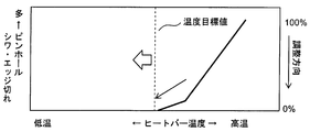
- the appearance defect detection unit 35a detects an appearance defect in the image data of the appearance of the heat-welded portion of the work. Specifically, as shown in FIG. 7, when the work is heat-welded at a temperature higher than a predetermined temperature, appearance defects such as wrinkles, edge breaks, and pinholes occur at the heat-welded portion of the work. It should be noted that this predetermined temperature can change due to variations in the lot of the work and variations in environmental conditions such as ambient temperature.
- the appearance defect detection unit 35a may detect wrinkles in the image data of the appearance of the heat-welded portion of the workpiece by detecting, for example, a shadow caused by light from an oblique direction.
- a portion of the transmitted light or reflected light of the work that has a higher or lower intensity than the surrounding may be cut as an edge and detected as a pinhole.
- a packaging defect inspection method for inspecting a packaging defect of a package in which a product is packaged with a packaging material is disclosed (for example, see Japanese Patent Laid-Open No. 2011-79564).
- the package is imaged from above while illuminating the package from all elevation angles in all directions around the package. After that, when there is a shadow that is a defect candidate, at least the length of the shadow is measured, and the measured length is used to determine whether or not the shadow is a defect.
- the program is not limited to these, and a commonly used program for appearance defect detection may be used.
- the display unit 33 may show, for example, the heat bar temperature (a), the work temperature (b), and the continuous sealing operation (c) for each heat seal in FIG. 6.
- FIG. 7 is a schematic diagram showing the relationship between the target temperature value and the appearance defect.
- the temperature target value correction unit 24 corrects the temperature target value of the heat seal unit 10 based on the appearance evaluation by the appearance evaluation unit 20. Specifically, the temperature target value correction unit 24 may correct the temperature target value of the heat seal unit 10 based on the appearance defect detected by the appearance defect detection unit 35a of the appearance evaluation unit 20. ..
- the temperature target value may be lowered by 1°C. That is, as shown in FIG. 7, the number of appearance defects increases as the temperature rises. Therefore, in this work heating device, the target temperature value is lowered in order to suppress the appearance defects.
- the target temperature value may be gradually lowered, but the lower limit temperature, which is the lower limit and is necessary for heat welding the work, may be set. The temperature target value may not be lowered below this lower limit temperature.
- the temperature target value correction unit 24 sends the corrected temperature target value as the manipulated variable 1 to the heater temperature control unit. Further, the temperature target value correction unit 24 may not correct the corrected temperature target value again within a predetermined time after the correction of the temperature target value. That is, when the target temperature value is corrected, it is necessary for the heater to follow the temperature for a certain period of time. Therefore, it is possible to roughly estimate the stabilization of the heater temperature as a predetermined time, and consider that the heater temperature is not stable within the predetermined time, and not correct the target temperature value.
- the predetermined time may be set as appropriate, but the temperature of the heater may be measured by a temperature sensor, and when the change width falls within a predetermined range, it may be determined that the heater temperature has stabilized.
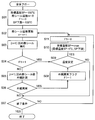
- FIG. 8 is a flowchart of the heat welding method for the work according to the first embodiment.
- an initial value is input, or an initial value input in advance is read (S01).
- the temperature target value SP is set to 150° C.
- the heat sealing number n is set to zero.
- the appearance abnormality flag F1 is set to 0.
- the lower limit of the temperature target value SP is 100°C.
- the number n of heat sealing is updated to n+1 (S02). Specifically, 1 is added to the heat sealing number n.
- Heat sealing is performed n times (S03). (4) It is determined whether the appearance abnormality flag F1 is 1 (S04).
- the process branches to No (S05). There may be a case where an abnormal appearance is detected after the second round, and in that case, the process branches to YES (S09). (5) If the appearance abnormality flag F1 is No, the appearance of the heat-sealed portion (heat-welded portion) is measured n times (S05).
- the temperature target value becomes cumulatively low before the heater temperature stabilizes. In this case, the temperature target value may be unintentionally lowered. In order to avoid such an inconvenience, it is effective to judge whether the heater temperature is stable. Instead of determining the stability of the heater temperature, it may be considered that the heater temperature is not stable within a predetermined time, and the process may branch to the determination of the next end condition (S07).
- the appearance of the heat-welded portion of the work is evaluated by the appearance evaluation unit, and feedback is provided to the heat seal unit based on the appearance evaluation. It can respond to changes in environmental conditions.
Landscapes
- Engineering & Computer Science (AREA)
- Mechanical Engineering (AREA)
- Lining Or Joining Of Plastics Or The Like (AREA)
- Package Closures (AREA)
Abstract
ワーク加熱装置は、ワークを加熱して熱溶着する熱シール部と、ワークの熱溶着部の外観を評価する外観評価部と、外観評価部による外観評価に基づいて、熱シール部の温度目標値を補正する温度目標値補正部と、を備える。
Description
本発明は、包材等のワークを熱溶着するワーク加熱装置に関する。特に、熱溶着するための熱シール部の温度制御技術に関する。
従来は、生産前に、ワークの熱溶着部に異常が発生しない条件を目視によって試行錯誤的に変更して決めていた。この場合の条件とは、例えば、熱溶着のための温度目標値、熱処理時間等の熱処理条件である。また、実際の生産時には、その熱処理条件を固定して運用していた。
例えば、非接触温度計を設け、該非接触温度計の検知信号に基づいて前記ヒータ線への通電時間又は導通角を制御するインパルスシール装置の温度制御方法が開示されている(例えば、特許文献1参照。)。
上記特許文献1の温度制御方法では、包材のロット変動や周囲温度等環境条件の変動によってシール強度や外観品質のばらつきが大きくなり、不良品が発生しやすい。例えば、包材の初期温度が上昇した場合、包材の厚さが薄くなった場合、及び、空調風量が減少した場合等には、熱シール部の温度が上昇し、ワークの熱溶着部にしわやピンホール等の外観不良が発生しやすくなる。
そこで、本発明の目的は、ワークのロット変動や周囲温度等環境条件の変動にも対応できるワーク加熱装置を提供することである。
本発明に係るワーク加熱装置は、ワークを加熱して熱溶着する熱シール部と、
前記ワークの熱溶着部の外観を評価する外観評価部と、
前記外観評価部による外観評価に基づいて、前記熱シール部の温度目標値を補正する温度目標値補正部と、
を備える。
前記ワークの熱溶着部の外観を評価する外観評価部と、
前記外観評価部による外観評価に基づいて、前記熱シール部の温度目標値を補正する温度目標値補正部と、
を備える。
本発明に係るワーク加熱装置によれば、外観評価部によってワークの熱溶着部の外観を評価して、その外観評価に基づいて、熱シール部にフィードバックするので、ワークのロット変動や周囲温度等環境条件の変動にも対応できる。
第1の態様に係るワーク加熱装置は、ワークを加熱して熱溶着する熱シール部と、
前記ワークの熱溶着部の外観を評価する外観評価部と、
前記外観評価部による外観評価に基づいて、前記熱シール部の温度目標値を補正する温度目標値補正部と、
を備える。
前記ワークの熱溶着部の外観を評価する外観評価部と、
前記外観評価部による外観評価に基づいて、前記熱シール部の温度目標値を補正する温度目標値補正部と、
を備える。
第2の態様に係るワーク加熱装置は、上記第1の態様において、前記外観評価部は、
前記ワークの熱溶着部の外観の画像データを取得する撮像部と、
前記ワークの熱溶着部の外観の前記画像データについて、外観不良を検出する外観不良検出部と、
を備え、
前記温度目標値補正部は、前記外観不良検出部で検出された前記外観不良に基づいて、前記熱シール部の温度目標値を引き下げるように補正してもよい。
前記ワークの熱溶着部の外観の画像データを取得する撮像部と、
前記ワークの熱溶着部の外観の前記画像データについて、外観不良を検出する外観不良検出部と、
を備え、
前記温度目標値補正部は、前記外観不良検出部で検出された前記外観不良に基づいて、前記熱シール部の温度目標値を引き下げるように補正してもよい。
第3の態様に係るワーク加熱装置は、上記第1又は第2の態様において、前記熱シール部は、
ヒータと、
前記ヒータの温度を計測する温度センサと、
前記温度センサで計測された温度に基づいて、前記ヒータの温度を温度目標値に近づけるように制御するヒータ温度制御部と、
を備えてもよい。
ヒータと、
前記ヒータの温度を計測する温度センサと、
前記温度センサで計測された温度に基づいて、前記ヒータの温度を温度目標値に近づけるように制御するヒータ温度制御部と、
を備えてもよい。
第4の態様に係るワーク加熱装置は、上記第3の態様において、前記ヒータ温度制御部は、あらかじめ入力された温度目標値を、前記温度目標値補正部で補正された補正後の温度目標値に置換して、前記ヒータの温度を前記補正後の温度目標値に近づけるように制御してもよい。
第5の態様に係るワーク加熱装置は、上記第3の態様において、前記外観評価部によって外観不良を検出し、前記温度目標値補正部において、前記温度目標値を補正した後、前記温度センサで計測された温度が安定したか否か判断し、温度が安定しない場合は、補正後の前記温度目標値を再度補正しなくてもよい。
第6の態様に係るワーク加熱装置は、上記第1から第4のいずれかの態様において、前記外観評価部によって外観不良を検出し、前記温度目標値補正部において、前記温度目標値を補正した後の所定時間内は、補正後の前記温度目標値を再度補正しなくてもよい。
第7の態様に係るワーク加熱装置は、上記第1から第6のいずれかの態様において、前記外観評価部によって外観不良を検出し、前記温度目標値補正部において、前記温度目標値を補正した場合、あらかじめ入力されている前記温度目標値を補正後の前記温度目標値に置換して記憶してもよい。
以下、実施の形態に係るワーク加熱装置について、添付図面を参照しながら説明する。なお、図面において実質的に同一の部材については同一の符号を付している。
(実施の形態1)
図1は、実施の形態1に係るワーク加熱装置40の構成を示すブロック図である。図2は、図1の外観評価部20の内部構成を示すブロック図である。図3は、図2の外観評価部20の物理的構成及び機能的構成を示すブロック図である。図4は、実施の形態1に係るワーク加熱装置のヒートバー2a、2bの外観の一例を示す概略図である。
実施の形態1に係るワーク加熱装置40は、熱シール部10と、外観評価部20と、温度目標値補正部24と、を備える。熱シール部10によってワーク1を加熱して熱溶着する。外観評価部20によって、ワーク1の熱溶着部の外観を評価する。温度目標値補正部24によって、外観評価部20による外観評価に基づいて、熱シール部10の温度目標値を補正する。
このワーク加熱装置40によれば、外観評価部20によってワーク1の熱溶着部の外観を評価して、その外観評価に基づいて、熱シール部10にフィードバックするので、ワーク1のロット変動や周囲温度等環境条件の変動にも対応できる。
図1は、実施の形態1に係るワーク加熱装置40の構成を示すブロック図である。図2は、図1の外観評価部20の内部構成を示すブロック図である。図3は、図2の外観評価部20の物理的構成及び機能的構成を示すブロック図である。図4は、実施の形態1に係るワーク加熱装置のヒートバー2a、2bの外観の一例を示す概略図である。
実施の形態1に係るワーク加熱装置40は、熱シール部10と、外観評価部20と、温度目標値補正部24と、を備える。熱シール部10によってワーク1を加熱して熱溶着する。外観評価部20によって、ワーク1の熱溶着部の外観を評価する。温度目標値補正部24によって、外観評価部20による外観評価に基づいて、熱シール部10の温度目標値を補正する。
このワーク加熱装置40によれば、外観評価部20によってワーク1の熱溶着部の外観を評価して、その外観評価に基づいて、熱シール部10にフィードバックするので、ワーク1のロット変動や周囲温度等環境条件の変動にも対応できる。
以下に、このワーク加熱装置40を構成する部材について説明する。
<熱シール部>
図5は、図4のワーク加熱装置のヒートバー2a、2bと温度センサ6を示す概略図である。
熱シール部10は、ヒートバー2と、ヒータ温度制御部8と、を備える。ヒートバー2、2a、2bは、図4及び図5に示すように、例えば、ワーク1を挟んで加熱して熱溶着する。また、図4及び図5の例ではワーク1を挟むように2つのヒートバー2a、2bを設けているが、これに限られず、1つのヒートバーであってもよい。なお、図4では、ワーク1は、連続する袋状であり、ヒートバー2a、2bによって所定間隔で熱溶着される。ヒートバー2は、図1及び図5に示すように、ヒータ4、4a、4bと、ヒータ4、4a、4bの温度を計測する温度センサ6とを備える。なお、ヒータ4a、4bは、図5に示すように2つのヒートバー2a、2bのそれぞれに設けてもよく、一方のヒートバーにのみ設けてもよい。また、温度センサ6は、ワーク1から所定間隔離れた箇所に設けているが、これに限られず、ワーク1に近接して設けてもよい。
図5は、図4のワーク加熱装置のヒートバー2a、2bと温度センサ6を示す概略図である。
熱シール部10は、ヒートバー2と、ヒータ温度制御部8と、を備える。ヒートバー2、2a、2bは、図4及び図5に示すように、例えば、ワーク1を挟んで加熱して熱溶着する。また、図4及び図5の例ではワーク1を挟むように2つのヒートバー2a、2bを設けているが、これに限られず、1つのヒートバーであってもよい。なお、図4では、ワーク1は、連続する袋状であり、ヒートバー2a、2bによって所定間隔で熱溶着される。ヒートバー2は、図1及び図5に示すように、ヒータ4、4a、4bと、ヒータ4、4a、4bの温度を計測する温度センサ6とを備える。なお、ヒータ4a、4bは、図5に示すように2つのヒートバー2a、2bのそれぞれに設けてもよく、一方のヒートバーにのみ設けてもよい。また、温度センサ6は、ワーク1から所定間隔離れた箇所に設けているが、これに限られず、ワーク1に近接して設けてもよい。
図6は、図4のヒートバーの温度とワーク1の温度とシール動作との関係を示す概略図である。図6(a)は、連続シール動作の間のヒートバーの温度を示す図である。図6(b)は、連続シール動作の間のワークの温度を示す図である。図6(c)は、連続シール動作の間の動作と停止とを示す概略図である。
ヒートバー2、2a、2bは、図6(a)に示すように、ワーク1の熱溶着のために温度目標値に近づけるように温度制御される。この場合、連続シール動作の開始と共にワークと接触するため、ヒートバーの温度はいくぶん低下し、連続シール動作の間は、ワークへの熱伝導が連続して行われる定常的な熱伝導が平衡状態となることで温度が安定する。なお、ワークの連続シールは、例えば、1つ当たり0.1秒~2秒で行われる。連続シールの終了とともにヒートバーの温度は温度目標値に近い温度に戻る。
ヒートバー2、2a、2bは、図6(a)に示すように、ワーク1の熱溶着のために温度目標値に近づけるように温度制御される。この場合、連続シール動作の開始と共にワークと接触するため、ヒートバーの温度はいくぶん低下し、連続シール動作の間は、ワークへの熱伝導が連続して行われる定常的な熱伝導が平衡状態となることで温度が安定する。なお、ワークの連続シールは、例えば、1つ当たり0.1秒~2秒で行われる。連続シールの終了とともにヒートバーの温度は温度目標値に近い温度に戻る。
ヒータ温度制御部8は、温度センサ6で計測された温度に基づいて、ヒータ4の温度を温度目標値に近づけるように制御する。ヒータ温度制御部8は、ヒータ4に例えば電流値又は電圧値等による操作量2によってヒータ4を制御する。また、ヒータ温度制御部8は、あらかじめ入力された初期値である温度目標値を有する。この温度目標値は、後述するように、温度目標値補正部からの温度目標値補正量あるいは補正後の温度目標値自体の操作量1によって初期値の温度目標値を置換される。その後も、逐次、ヒータ温度制御部8では、温度目標値補正部からの温度目標値補正量の操作量1によって温度目標値を置換する。この場合、ヒータ温度制御部8で記憶している初期値の温度目標値を補正後の温度目標値に置換して記憶してもよく、あるいは、初期値の温度目標値を保持していてもよい。補正後の温度目標値に置換して記憶した場合には、一度でも外観不良が発生した温度目標値は更新しておくことで、再度の外観不良の発生を抑制できる。一方、初期値の温度目標値を保持しておき、新たな動作時には再度初期値の温度目標値を読み出してもよい。この場合、毎回異なるロット変動や周囲温度等環境条件の変動に適宜対応させることができる。
<外観評価部>
図3は、図2の外観評価部20の物理的構成及び機能的構成を示すブロック図である。
外観評価部20は、図2に示すように、例えば、撮像部22と、外観不良検出部35aとを含む。また、外観評価部20は、物理的構成及び機能的構成の観点では、図3に示すように、撮像部22と制御部30とを含む。撮像部22によって、ワークの熱溶着部の外観の画像データを取得する。外観不良検出部35aによって、ワークの熱溶着部の外観の前記画像データについて、外観不良を検出する。
図3は、図2の外観評価部20の物理的構成及び機能的構成を示すブロック図である。
外観評価部20は、図2に示すように、例えば、撮像部22と、外観不良検出部35aとを含む。また、外観評価部20は、物理的構成及び機能的構成の観点では、図3に示すように、撮像部22と制御部30とを含む。撮像部22によって、ワークの熱溶着部の外観の画像データを取得する。外観不良検出部35aによって、ワークの熱溶着部の外観の前記画像データについて、外観不良を検出する。
<制御部(コンピュータ装置)>
制御部30は、例えば、コンピュータ装置である。このコンピュータ装置としては、汎用的なコンピュータ装置を用いることができ、例えば、図3に示すように、処理部31、記憶部32、表示部33を含む。なお、さらに、入力装置、記憶装置、インタフェース等を含んでもよい。制御部30によって、撮像部22を制御している。
制御部30は、例えば、コンピュータ装置である。このコンピュータ装置としては、汎用的なコンピュータ装置を用いることができ、例えば、図3に示すように、処理部31、記憶部32、表示部33を含む。なお、さらに、入力装置、記憶装置、インタフェース等を含んでもよい。制御部30によって、撮像部22を制御している。
<処理部>
処理部31は、例えば、中央処理演算子(CPU)、マイクロコンピュータ、又は、コンピュータで実行可能な命令を実行できる処理装置であればよい。
処理部31は、例えば、中央処理演算子(CPU)、マイクロコンピュータ、又は、コンピュータで実行可能な命令を実行できる処理装置であればよい。
<記憶部>
記憶部32は、例えば、ROM、EEPROM、RAM、フラッシュSSD、ハードディスク、USBメモリ、磁気ディスク、光ディスク、光磁気ディスク等の少なくとも一つであってもよい。
記憶部32には、プログラム35を含む。なお、制御部30がネットワークに接続されている場合には、必要に応じてプログラム35をネットワークからダウンロードしてもよい。
記憶部32は、例えば、ROM、EEPROM、RAM、フラッシュSSD、ハードディスク、USBメモリ、磁気ディスク、光ディスク、光磁気ディスク等の少なくとも一つであってもよい。
記憶部32には、プログラム35を含む。なお、制御部30がネットワークに接続されている場合には、必要に応じてプログラム35をネットワークからダウンロードしてもよい。
<プログラム>
プログラム35には、外観不良検出部35aを含んでいればよい。外観不良検出部35aによって、ワークの熱溶着部の外観の画像データについて、外観不良を検出する。具体的には、図7に示すように、ワークを所定温度より高温で熱溶着を行った場合、ワークの熱溶着部にしわ、エッジ切れ、ピンホール等の外観不良が発生する。なお、この所定温度は、ワークのロット変動や周囲温度等の環境条件の変動によって変化しうるものである。外観不良検出部35aでは、ワークの熱溶着部の外観の画像データについて、例えば、斜め方向からの光による影を検出して、しわを検出してもよい。あるいは、ワークの透過光又は反射光について周囲より強度が強い又は弱い箇所をエッジ切れ、ピンホールとして検出してもよい。例えば、製品を包装材で包装した包装体の包装不良を検査する包装不良検査方法が開示されている(例えば、特開2011-79564号公報参照。)。この検査方法では、包装体に対して前記包装体を中心とする全方向の全仰角から照明しながら包装体を上方から撮像している。その後、欠陥候補となる影が存在する場合、少なくとも前記影の長さを計測し、計測された長さを用いて影が欠陥であるか否かを判定している。
なお、これらに限られず、一般的に利用される外観不良検出のためのプログラムを利用してもよい。
プログラム35には、外観不良検出部35aを含んでいればよい。外観不良検出部35aによって、ワークの熱溶着部の外観の画像データについて、外観不良を検出する。具体的には、図7に示すように、ワークを所定温度より高温で熱溶着を行った場合、ワークの熱溶着部にしわ、エッジ切れ、ピンホール等の外観不良が発生する。なお、この所定温度は、ワークのロット変動や周囲温度等の環境条件の変動によって変化しうるものである。外観不良検出部35aでは、ワークの熱溶着部の外観の画像データについて、例えば、斜め方向からの光による影を検出して、しわを検出してもよい。あるいは、ワークの透過光又は反射光について周囲より強度が強い又は弱い箇所をエッジ切れ、ピンホールとして検出してもよい。例えば、製品を包装材で包装した包装体の包装不良を検査する包装不良検査方法が開示されている(例えば、特開2011-79564号公報参照。)。この検査方法では、包装体に対して前記包装体を中心とする全方向の全仰角から照明しながら包装体を上方から撮像している。その後、欠陥候補となる影が存在する場合、少なくとも前記影の長さを計測し、計測された長さを用いて影が欠陥であるか否かを判定している。
なお、これらに限られず、一般的に利用される外観不良検出のためのプログラムを利用してもよい。
<表示部>
表示部33は、例えば、図6の各熱シールごとのヒートバー温度(a)、ワーク温度(b)、及び、連続シール動作(c)を示してもよい。
表示部33は、例えば、図6の各熱シールごとのヒートバー温度(a)、ワーク温度(b)、及び、連続シール動作(c)を示してもよい。
<温度目標値補正部>
図7は、温度目標値と外観不良の発生との関係とを示す概略図である。
温度目標値補正部24は、外観評価部20による外観評価に基づいて、熱シール部10の温度目標値を補正する。具体的には、温度目標値補正部24は、外観評価部20の外観不良検出部35aで検出された外観不良に基づいて、熱シール部10の温度目標値を引き下げるように補正してもよい。例えば、温度目標値を1℃引き下げてもよい。つまり、図7に示すように、高温になるにつれて外観不良の数が増加するので、外観不良の発生を抑制するために、このワーク加熱装置では、温度目標値を引き下げている。なお、温度目標値は、逐次引き下げていってもよいが、下限となる、ワークの熱溶着に必要な下限温度を設定しておいてもよい。温度目標値は、この下限温度より下には下げないこととしてもよい。
図7は、温度目標値と外観不良の発生との関係とを示す概略図である。
温度目標値補正部24は、外観評価部20による外観評価に基づいて、熱シール部10の温度目標値を補正する。具体的には、温度目標値補正部24は、外観評価部20の外観不良検出部35aで検出された外観不良に基づいて、熱シール部10の温度目標値を引き下げるように補正してもよい。例えば、温度目標値を1℃引き下げてもよい。つまり、図7に示すように、高温になるにつれて外観不良の数が増加するので、外観不良の発生を抑制するために、このワーク加熱装置では、温度目標値を引き下げている。なお、温度目標値は、逐次引き下げていってもよいが、下限となる、ワークの熱溶着に必要な下限温度を設定しておいてもよい。温度目標値は、この下限温度より下には下げないこととしてもよい。
なお、温度目標値補正部24は、補正された補正後の温度目標値を操作量1として、ヒータ温度制御部に送信する。また、温度目標値補正部24において、温度目標値を補正した後の所定時間内は、補正後の温度目標値を再度補正しないでもよい。つまり、温度目標値を補正した場合、ヒータにおける温度追従には一定時間必要となる。そこで、ヒータ温度の安定までを所定時間として概算し、所定時間内はヒータ温度が安定していないものとみなして、温度目標値の補正を行わないこととしてもよい。この場合、所定時間は、適宜設定すればよいが、温度センサによってヒータの温度を計測して、その変化幅が所定範囲内となった場合にヒータ温度が安定したと判断してもよい。
<ワークの熱溶着方法>
図8は、実施の形態1に係るワークの熱溶着方法のフローチャートである。
(1)まず、初期値を入力するか、あるいは、あらかじめ入力された初期値を読み込む(S01)。具体的には、温度目標値SPを150℃に設定し、熱シール回数nを0とする。また、外観異常フラグF1を0とする。なお、温度目標値SPの下限値を100℃とする。
(2)熱シール回数nをn+1に更新する(S02)。具体的には熱シール回数nに1を加算する。
(3)n回め熱シールを実行する(S03)。
(4)外観異常フラグF1が1であるか否か判断する(S04)。なお、最初に行う際には外観異常フラグF1は0であるので、No(S05)へ分岐する。2周目以降には、外観異常を検出している場合があり、その場合には、YES(S09)へ分岐する。
(5)外観異常フラグF1の判断がNoの場合に、n回め熱シール部(熱溶着部)の外観計測を行う(S05)。
図8は、実施の形態1に係るワークの熱溶着方法のフローチャートである。
(1)まず、初期値を入力するか、あるいは、あらかじめ入力された初期値を読み込む(S01)。具体的には、温度目標値SPを150℃に設定し、熱シール回数nを0とする。また、外観異常フラグF1を0とする。なお、温度目標値SPの下限値を100℃とする。
(2)熱シール回数nをn+1に更新する(S02)。具体的には熱シール回数nに1を加算する。
(3)n回め熱シールを実行する(S03)。
(4)外観異常フラグF1が1であるか否か判断する(S04)。なお、最初に行う際には外観異常フラグF1は0であるので、No(S05)へ分岐する。2周目以降には、外観異常を検出している場合があり、その場合には、YES(S09)へ分岐する。
(5)外観異常フラグF1の判断がNoの場合に、n回め熱シール部(熱溶着部)の外観計測を行う(S05)。
(6)外観異常の有無を判断する(S06)。外観異常がないと判断された場合には、No(S07)へ分岐する。外観異常があると判断された場合には、YES(S08)へ分岐する。
(7)終了条件を満たすか判断する(S07)。終了条件は、例えば、熱シール回数nが予定のシール回数に達した場合、停止ボタンが押された場合、等である。終了条件を満たす場合には、YESへ分岐し、終了する。終了条件を満たさない場合には、No(S02)へ分岐し、熱シール回数の更新に戻る。なお、終了条件は、上記の場合に限られない。
(7)終了条件を満たすか判断する(S07)。終了条件は、例えば、熱シール回数nが予定のシール回数に達した場合、停止ボタンが押された場合、等である。終了条件を満たす場合には、YESへ分岐し、終了する。終了条件を満たさない場合には、No(S02)へ分岐し、熱シール回数の更新に戻る。なお、終了条件は、上記の場合に限られない。
(8)S06で外観異常があると判断された場合(YES)には、外観異常フラグF1に1を代入する(S08)。次いで、S09へ移行する。
(9)ヒータ温度が安定か判断する(S09)。ヒータ温度は、温度センサで計測された温度である。このヒータ温度は、熱シールごとのヒートバーの最大温度、最小温度、又は平均温度のいずれであってもよい。ヒータ温度が安定な場合には、YES(S10)へ分岐する。ヒータ温度が安定でないと判断された場合には、No(S07)へ分岐する。これは、温度目標値の補正があった場合に、ヒータにおける温度追従には一定時間必要となることを考慮するためである。つまり、たとえ温度目標値の補正があってもヒータの温度は直ちに下がらないので、そのまま外観評価を行うと、再び外観不良を検出する場合がある。その結果、ヒータ温度が安定する前に温度目標値が累積的に低くなるという問題がある。この場合には、意図しないほどに温度目標値が低くなる可能性がある。このような不都合を回避するため、ヒータ温度が安定したか判断することが有効となる。なお、ヒータ温度の安定を判断することに代えて、所定時間内はヒータ温度が安定していないものとみなして、次の終了条件の判断(S07)へ分岐してもよい。
(9)ヒータ温度が安定か判断する(S09)。ヒータ温度は、温度センサで計測された温度である。このヒータ温度は、熱シールごとのヒートバーの最大温度、最小温度、又は平均温度のいずれであってもよい。ヒータ温度が安定な場合には、YES(S10)へ分岐する。ヒータ温度が安定でないと判断された場合には、No(S07)へ分岐する。これは、温度目標値の補正があった場合に、ヒータにおける温度追従には一定時間必要となることを考慮するためである。つまり、たとえ温度目標値の補正があってもヒータの温度は直ちに下がらないので、そのまま外観評価を行うと、再び外観不良を検出する場合がある。その結果、ヒータ温度が安定する前に温度目標値が累積的に低くなるという問題がある。この場合には、意図しないほどに温度目標値が低くなる可能性がある。このような不都合を回避するため、ヒータ温度が安定したか判断することが有効となる。なお、ヒータ温度の安定を判断することに代えて、所定時間内はヒータ温度が安定していないものとみなして、次の終了条件の判断(S07)へ分岐してもよい。
(10)温度目標値SPに元の温度目標値から1℃下げた値(SP-1℃)とSP下限温度とのうち、より高い値を温度目標値SPに代入する(S10)。つまり、下限温度、例えば、100℃以上の範囲で温度目標値SPを1℃下げた値(SP-1℃)を新たな温度目標値とする。なお、関数max(a,b)は、a,bのうち、より大きい値を返す。その後、S11に移行する。
(11)外観異常フラグF1に0を代入する(S11)。その後、S02へ移行する。
以上の工程によって、ワークの熱溶着を行うことができる。
(11)外観異常フラグF1に0を代入する(S11)。その後、S02へ移行する。
以上の工程によって、ワークの熱溶着を行うことができる。
上記ワークの熱溶着方法によって、ワークのロット変動や周囲温度等環境条件の変動があった場合にも、追従して対応できる。つまり、ロット変動や環境条件の変動により、外観不良が発生した場合には、熱溶着の温度が適切な温度範囲より高温になっていることを意味している(図7)。そこで、外観不良を検出した場合には、熱シール部の温度目標値を下げることによって、適切な温度範囲での熱溶着を実現できるようになる。
なお、本開示においては、前述した様々な実施の形態及び/又は実施例のうちの任意の実施の形態及び/又は実施例を適宜組み合わせることを含むものであり、それぞれの実施の形態及び/又は実施例が有する効果を奏することができる。
本発明に係るワーク加熱装置によれば、外観評価部によってワークの熱溶着部の外観を評価して、その外観評価に基づいて、熱シール部にフィードバックするので、ワークのロット変動や周囲温度等環境条件の変動にも対応できる。
1 ワーク
2、2a、2b ヒートバー
4、4a、4b ヒータ
6 温度センサ
8 ヒータ温度制御部
10 熱シール部
20 外観評価部
22 撮像部
24 温度目標値補正部
30 制御部(コンピュータ装置)
31 処理部
32 記憶部
33 表示部
35 プログラム
35a 外観不良検出部
40 ワーク加熱装置
2、2a、2b ヒートバー
4、4a、4b ヒータ
6 温度センサ
8 ヒータ温度制御部
10 熱シール部
20 外観評価部
22 撮像部
24 温度目標値補正部
30 制御部(コンピュータ装置)
31 処理部
32 記憶部
33 表示部
35 プログラム
35a 外観不良検出部
40 ワーク加熱装置
Claims (7)
- ワークを加熱して熱溶着する熱シール部と、
前記ワークの熱溶着部の外観を評価する外観評価部と、
前記外観評価部による外観評価に基づいて、前記熱シール部の温度目標値を補正する温度目標値補正部と、
を備えた、ワーク加熱装置。 - 前記外観評価部は、
前記ワークの熱溶着部の外観の画像データを取得する撮像部と、
前記ワークの熱溶着部の外観の前記画像データについて、外観不良を検出する外観不良検出部と、
を備え、
前記温度目標値補正部は、前記外観不良検出部で検出された前記外観不良に基づいて、前記熱シール部の温度目標値を引き下げるように補正する、請求項1に記載のワーク加熱装置。 - 前記熱シール部は、
ヒータと、
前記ヒータの温度を計測する温度センサと、
前記温度センサで計測された温度に基づいて、前記ヒータの温度を温度目標値に近づけるように制御するヒータ温度制御部と、
を備えた、請求項1又は2に記載のワーク加熱装置。 - 前記ヒータ温度制御部は、あらかじめ入力された温度目標値を、前記温度目標値補正部で補正された補正後の温度目標値に置換して、前記ヒータの温度を前記補正後の温度目標値に近づけるように制御する、請求項3に記載のワーク加熱装置。
- 前記外観評価部によって外観不良を検出し、前記温度目標値補正部において、前記温度目標値を補正した後、前記温度センサで計測された温度が安定したか否か判断し、温度が安定しない場合は、補正後の前記温度目標値を再度補正しない、請求項3に記載のワーク加熱装置。
- 前記外観評価部によって外観不良を検出し、前記温度目標値補正部において、前記温度目標値を補正した後の所定時間内は、補正後の前記温度目標値を再度補正しない、請求項1から4のいずれか一項に記載のワーク加熱装置。
- 前記外観評価部によって外観不良を検出し、前記温度目標値補正部において、前記温度目標値を補正した場合、あらかじめ入力されている前記温度目標値を補正後の前記温度目標値に置換して記憶する、請求項1から6のいずれか一項に記載のワーク加熱装置。
Applications Claiming Priority (2)
| Application Number | Priority Date | Filing Date | Title |
|---|---|---|---|
| JP2019-024459 | 2019-02-14 | ||
| JP2019024459A JP2020132165A (ja) | 2019-02-14 | 2019-02-14 | ワーク加熱装置 |
Publications (1)
| Publication Number | Publication Date |
|---|---|
| WO2020166332A1 true WO2020166332A1 (ja) | 2020-08-20 |
Family
ID=72045606
Family Applications (1)
| Application Number | Title | Priority Date | Filing Date |
|---|---|---|---|
| PCT/JP2020/003119 Ceased WO2020166332A1 (ja) | 2019-02-14 | 2020-01-29 | ワーク加熱装置 |
Country Status (2)
| Country | Link |
|---|---|
| JP (1) | JP2020132165A (ja) |
| WO (1) | WO2020166332A1 (ja) |
Families Citing this family (1)
| Publication number | Priority date | Publication date | Assignee | Title |
|---|---|---|---|---|
| WO2022053401A1 (en) * | 2020-09-10 | 2022-03-17 | Tetra Laval Holdings & Finance S.A. | A method for assessing quality of a longitudinal sealing and a server |
Citations (2)
| Publication number | Priority date | Publication date | Assignee | Title |
|---|---|---|---|---|
| JP2005007845A (ja) * | 2003-06-20 | 2005-01-13 | Kazuo Hishinuma | ヒートシール条件のシミュレーション方法 |
| JP2010132290A (ja) * | 2008-12-02 | 2010-06-17 | Nisshin Foods Kk | 包装袋のヒートシール方法 |
Family Cites Families (3)
| Publication number | Priority date | Publication date | Assignee | Title |
|---|---|---|---|---|
| JP2006069641A (ja) * | 2004-09-03 | 2006-03-16 | Fujimori Kogyo Co Ltd | ヒートシール装置、充填密封装置、ヒートシール方法、充填密封方法、製袋充填装置 |
| JP2018127238A (ja) * | 2017-02-07 | 2018-08-16 | 株式会社New IWASHO | シール装置 |
| JP6172784B1 (ja) * | 2017-02-22 | 2017-08-02 | 株式会社悠心 | 包装体の画像検査システム |
-
2019
- 2019-02-14 JP JP2019024459A patent/JP2020132165A/ja active Pending
-
2020
- 2020-01-29 WO PCT/JP2020/003119 patent/WO2020166332A1/ja not_active Ceased
Patent Citations (2)
| Publication number | Priority date | Publication date | Assignee | Title |
|---|---|---|---|---|
| JP2005007845A (ja) * | 2003-06-20 | 2005-01-13 | Kazuo Hishinuma | ヒートシール条件のシミュレーション方法 |
| JP2010132290A (ja) * | 2008-12-02 | 2010-06-17 | Nisshin Foods Kk | 包装袋のヒートシール方法 |
Also Published As
| Publication number | Publication date |
|---|---|
| JP2020132165A (ja) | 2020-08-31 |
Similar Documents
| Publication | Publication Date | Title |
|---|---|---|
| JP4884472B2 (ja) | レーザ溶接されたバッテリモジュール筐体部品の赤外線熱画像化 | |
| US8541746B2 (en) | Process and system for the nondestructive quality determination of a weld seam, and a welding device | |
| KR102223770B1 (ko) | 검사 방법 및 장치 | |
| JP5689969B2 (ja) | ビードフィラー検査装置、ビードフィラー検査用プログラム及びビードフィラー検査方法 | |
| WO2020260278A1 (en) | A package seal control system, an upgrade kit, and a method for monitoring and optionally controlling the longitudinal seal of a package material in a packaging and filling machine | |
| JP2003307505A (ja) | サーモグラフィによる非接触検査装置及びその非接触検査方法 | |
| JP6364353B2 (ja) | ホイルを有するパッケージのシーリング中に欠陥を検出する装置と方法 | |
| TW202136711A (zh) | 檢查裝置及熔接裝置 | |
| KR20150088560A (ko) | 용접 검사 장치 | |
| JP2017129566A (ja) | 構造のバリエーションを検知するためのx線散乱システムおよび方法 | |
| JP6255713B2 (ja) | 光学非破壊検査方法及び光学非破壊検査装置 | |
| JP2014151360A (ja) | 溶接品質検査方法 | |
| JP2020132165A (ja) | ワーク加熱装置 | |
| KR102715840B1 (ko) | 써모커플 센서의 온도 계측 장치 및 그를 이용한 선박 대형 엔진 시운전용 데이터 계측 시스템 | |
| TWI746553B (zh) | 用於檢測被夾合在對焊機中的塑膠管端部的方法、以及藉由管端部的檢測之用於塑膠管端部的對焊的設備 | |
| KR102008704B1 (ko) | 용접 소재의 두께 측정 장치 및 이를 이용한 용접 방법 | |
| JP2015101368A (ja) | ヒートシール品質管理装置およびヒートシール装置 | |
| JP6594250B2 (ja) | 温度計測装置及び温度計測方法 | |
| WO2020166333A1 (ja) | ワーク加熱装置 | |
| JP2018127238A (ja) | シール装置 | |
| JP7273786B2 (ja) | フィルム型電池の検査装置および製造方法 | |
| CN115768580A (zh) | 为在工件上进行的焊接过程确定焊接参数的方法以及用确定的焊接参数在工件上执行焊接过程的焊接装置 | |
| JP2011033459A (ja) | 包装袋のシール幅測定装置 | |
| JP4312474B2 (ja) | スパウト取付装置の検査システム | |
| JP2019156434A (ja) | 検査システム、検査装置、検査方法 |
Legal Events
| Date | Code | Title | Description |
|---|---|---|---|
| 121 | Ep: the epo has been informed by wipo that ep was designated in this application |
Ref document number: 20755546 Country of ref document: EP Kind code of ref document: A1 |
|
| NENP | Non-entry into the national phase |
Ref country code: DE |
|
| 122 | Ep: pct application non-entry in european phase |
Ref document number: 20755546 Country of ref document: EP Kind code of ref document: A1 |