WO2020166145A1 - 切削工具 - Google Patents
切削工具 Download PDFInfo
- Publication number
- WO2020166145A1 WO2020166145A1 PCT/JP2019/043269 JP2019043269W WO2020166145A1 WO 2020166145 A1 WO2020166145 A1 WO 2020166145A1 JP 2019043269 W JP2019043269 W JP 2019043269W WO 2020166145 A1 WO2020166145 A1 WO 2020166145A1
- Authority
- WO
- WIPO (PCT)
- Prior art keywords
- recess
- cutting edge
- cutting tool
- cutting
- recesses
- Prior art date
- Legal status (The legal status is an assumption and is not a legal conclusion. Google has not performed a legal analysis and makes no representation as to the accuracy of the status listed.)
- Ceased
Links
Images




Classifications
-
- B—PERFORMING OPERATIONS; TRANSPORTING
- B23—MACHINE TOOLS; METAL-WORKING NOT OTHERWISE PROVIDED FOR
- B23B—TURNING; BORING
- B23B27/00—Tools for turning or boring machines; Tools of a similar kind in general; Accessories therefor
- B23B27/14—Cutting tools of which the bits or tips or cutting inserts are of special material
-
- B—PERFORMING OPERATIONS; TRANSPORTING
- B23—MACHINE TOOLS; METAL-WORKING NOT OTHERWISE PROVIDED FOR
- B23B—TURNING; BORING
- B23B51/00—Tools for drilling machines
-
- B—PERFORMING OPERATIONS; TRANSPORTING
- B23—MACHINE TOOLS; METAL-WORKING NOT OTHERWISE PROVIDED FOR
- B23C—MILLING
- B23C5/00—Milling-cutters
- B23C5/16—Milling-cutters characterised by physical features other than shape
- B23C5/20—Milling-cutters characterised by physical features other than shape with removable cutter bits or teeth or cutting inserts
Definitions
- Patent Document 1 discloses a cutting tool having a large number of grooves on the rake face. High lubricity can be obtained by collecting the cutting fluid in the groove.
- Patent Document 2 discloses a cutting tool having a patterned surface region.
- FIG. 1 is a schematic perspective view showing the configuration of the cutting tool according to the first embodiment.
- FIG. 2 is an enlarged schematic plan view showing the configuration of the cutting tool according to the first embodiment.
- FIG. 3 is a schematic sectional view taken along the line III-III in FIG.
- FIG. 4 is a schematic cross-sectional view showing the configuration of the cutting tool according to the first modified example of the first embodiment.
- FIG. 5 is a cross-sectional schematic diagram which shows the structure of the cutting tool which concerns on the 2nd modification of 1st Embodiment.
- FIG. 6 is an enlarged schematic plan view showing the configuration of the cutting tool according to the second embodiment.
- FIG. 7 is an enlarged schematic plan view showing the configuration of the cutting tool according to the third embodiment.
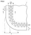
- FIG. 8 is an enlarged schematic plan view showing the configuration of the cutting tool according to the fourth embodiment.
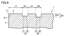
- FIG. 9 is a schematic sectional view taken along the line IX-IX in FIG.
- FIG. 10 is an enlarged schematic plan view showing the configuration of the cutting tool according to the fifth embodiment.
- FIG. 11 is a schematic sectional view taken along the line XI-XI of FIG.
- FIG. 12 is an enlarged schematic plan view showing the configuration of the cutting tool according to the sixth embodiment.
- FIG. 13 is a schematic sectional view taken along line XIII-XIII in FIG.
- FIG. 14 is a schematic sectional view showing the configuration of the cutting tool according to the seventh embodiment.
- An object of the present disclosure is to provide a cutting tool capable of reducing wear on a rake face.
- a cutting tool capable of reducing wear on a rake face According to the present disclosure, it is possible to provide a cutting tool capable of reducing wear on a rake face.
- the depth of the first recess 10 may be 50 ⁇ m or less in the direction perpendicular to the seat surface 5. If the depth of the first recessed portion 10 is large, the strength of the cutting edge 4 becomes low, and the cutting edge 4 is easily damaged. By setting the depth of the first recess 10 to be 50 ⁇ m or less, the cutting edge 4 can be prevented from being damaged.
- FIG. 2 is an enlarged schematic plan view showing the configuration of the cutting tool according to the first embodiment.
- the cutting edge 4 has a first cutting edge portion 4a, a corner cutting edge portion 4b, and a second cutting edge portion 4c when viewed from a direction perpendicular to the seat surface 5. doing.
- Each of the 1st cutting edge part 4a and the 2nd cutting edge part 4c is linear.
- the corner cutting edge portion 4b is located between the first cutting edge portion 4a and the second cutting edge portion 4c.
- the corner cutting edge portion 4b has an arc shape.
- the inner end portion 8 is a line connecting a straight line parallel to the first cutting edge portion 4a, a curve having the same curvature as the corner cutting edge portion 4b, and a straight line parallel to the second cutting edge portion 4c.
- the outer end portion 7 is a line connecting a straight line parallel to the first cutting edge part 4a, a curve having the same curvature as the corner cutting edge part 4b, and a straight line parallel to the second cutting edge part 4c. is there.
- the plurality of recesses 100 are provided in a region (recess formation region 9) between the inner end 8 and the outer end 7.
- the shape of at least a part of each of the plurality of recesses 100 may be a circle when viewed from a direction perpendicular to the seat surface 5. All the shapes of the plurality of recesses 100 may be circular, or part of the plurality of recesses 100 may be circular.
- the interval (fifth length G1) between two adjacent recesses of the plurality of recesses 100 is, for example, 10 ⁇ m or more.
- the interval (fifth length G1) between two adjacent recesses in the plurality of recesses 100 may be smaller than the width (fifth width T1) of the recesses in the direction parallel to the extending direction of the cutting edge 4. ..
- the cutting tool 1 according to the second embodiment is different from the cutting tool 1 according to the first embodiment mainly in the configuration in which the shape of the recess is rectangular, and the other configurations are the cutting according to the first embodiment. It is similar to the tool 1.
- the configuration different from the cutting tool 1 according to the first embodiment will be mainly described.
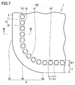
- FIG. 7 is an enlarged schematic plan view showing the configuration of the cutting tool 1 according to the third embodiment.
- the shape of at least a part of each of the plurality of recesses 100 may be a hexagon when viewed in a direction perpendicular to the seat surface 5. All the shapes of the plurality of recesses 100 may be hexagonal, or some shapes of the plurality of recesses 100 may be hexagonal. Preferably, all the shapes of the plurality of recesses 100 are regular hexagons.
- the two opposite sides of the hexagonal recessed portion located in the area facing the first cutting edge portion 4a have the first It may or may not have a special angle with the extending direction of the cutting edge portion 4a.
- the two opposite sides of the hexagonal recessed portion located in the region facing the second cutting edge portion 4c have the extending direction of the second cutting edge portion 4c. It may be parallel to a direction perpendicular to.
- the cutting tool 1 according to the fourth embodiment is different from the cutting tool 1 according to the first embodiment mainly in the configuration in which the plurality of recesses 100 have the first recess 10, the second recess 20, and the third recess 30.
- the other configurations are the same as those of the cutting tool 1 according to the first embodiment.
- the configuration different from the cutting tool 1 according to the first embodiment will be mainly described.
- FIG. 9 is a schematic sectional view taken along line IX-IX in FIG.
- the rake face 2 is provided with a first recess 10 and a second recess 20.
- the second recess 20 has a second side surface 21 and a second bottom surface 22.
- the second side surface 21 may extend in a direction substantially perpendicular to the rake surface 2.
- the second bottom surface 22 is continuous with the second side surface 21.
- the second bottom surface 22 may be substantially parallel to the rake surface 2.
- the depth of the second recess 20 (second depth D2) is smaller than the depth of the first recess 10 (first depth D1). May be larger.
- the second depth D2 is, for example, 200 ⁇ m or less.
- the second depth D2 is preferably 100 ⁇ m or less, more preferably 50 ⁇ m or less.
- the lower limit of the second depth D2 is not particularly limited, but is, for example, 10 ⁇ m or more.
- the cutting tool 1 according to the fifth embodiment is different from the cutting tool 1 according to the first embodiment mainly in the configuration in which each of the plurality of recesses 100 is an elongated groove, and other configurations are as follows. It is similar to the cutting tool 1 according to one embodiment.
- the configuration different from the cutting tool 1 according to the first embodiment will be mainly described.
- FIG. 10 is an enlarged schematic plan view showing the configuration of the cutting tool according to the fifth embodiment.
- the plurality of recesses 100 has a first recess 10, a second recess 20, and a third recess 30.
- the first recess 10 is located closest to the cutting edge 4 when viewed in a direction perpendicular to the seat surface 5.
- the second recess 20 is located farthest from the cutting edge 4 when viewed in a direction perpendicular to the seat surface 5.
- the third recess 30 is located between the first recess 10 and the second recess 20 when viewed from a direction perpendicular to the seat surface 5.
- the shortest distance between the first recess 10 and the cutting edge 4 is smaller than the shortest distance between the second recess 20 and the cutting edge 4. short.
- the shortest distance between the third concave portion 30 and the cutting edge 4 is longer than the shortest distance between the first concave portion 10 and the cutting edge 4, and the second concave portion 20. Is shorter than the shortest distance from the cutting edge 4.
- each shape of the first recess 10, the second recess 20, and the third recess 30 is an elongated groove when viewed from a direction perpendicular to the seat surface 5.
- the elongated groove has a portion parallel to the first cutting edge portion 4a, a portion having the same curvature as the corner cutting edge portion 4b, and a portion parallel to the second cutting edge portion 4c.
- each of the first recess 10, the second recess 20, and the third recess 30 is provided along the cutting edge 4 when viewed in the direction perpendicular to the seat surface 5.
- the first recess 10 and the second recess 20 may have similar shapes when viewed from a direction perpendicular to the seat surface 5.
- the first recess 10 and the third recess 30 may have similar shapes when viewed from a direction perpendicular to the seat surface 5.
- FIG. 11 is a schematic sectional view taken along line XI-XI in FIG.
- the rake face 2 is provided with a first recess 10, a second recess 20, and a third recess 30.
- the second recess 20 has a second side surface 21 and a second bottom surface 22.
- the second side surface 21 may extend in a direction substantially perpendicular to the rake surface 2.
- the second bottom surface 22 is continuous with the second side surface 21.
- the second bottom surface 22 may be substantially parallel to the rake surface 2.
- the third recess 30 has a third side surface 31 and a third bottom surface 32.
- the third side surface 31 may extend in a direction substantially perpendicular to the rake face 2.
- the third bottom surface 32 is continuous with the third side surface 31.
- the third bottom surface 32 may be substantially parallel to the rake surface 2.
- the depth of the third recess 30 may be larger than the depth of the first recess 10 (first depth D1).
- the depth of the second recess 20 (second depth D2) may be larger than the depth of the third recess 30 (third depth D3).
- the first depth D1 may be the same as the second depth D2.
- the second depth D2 may be the same as the third depth D3.
- the distance between the first recess 10 and the third recess 30 is smaller than the shortest distance between the cutting edge 4 and the first recess 10 (first length L1). It may be small.
- the width of the first recess 10 (first width W1) may be the same as or different from the width of the second recess 20 (second width W2).
- the width of the second recess 20 (second width W2) may be the same as or different from the width of the third recess 30 (third width W3).
- the cutting tool 1 according to the sixth embodiment is mainly configured such that the plurality of recesses 100 have the first recess 10, the second recess 20, the third recess 30, and the fourth recess 40, and the cutting according to the first embodiment. It is different from the tool 1, and the other configurations are the same as those of the cutting tool 1 according to the first embodiment.
- the configuration different from the cutting tool 1 according to the first embodiment will be mainly described.
- FIG. 12 is an enlarged schematic plan view showing the configuration of the cutting tool according to the sixth embodiment.
- the plurality of recesses 100 has a first recess 10, a second recess 20, a third recess 30, and a fourth recess 40.
- the first recess 10 is located closest to the cutting edge 4 when viewed in a direction perpendicular to the seat surface 5.
- the second recess 20 is located farthest from the cutting edge 4 when viewed in a direction perpendicular to the seat surface 5.
- the third recess 30 is located between the first recess 10 and the second recess 20 when viewed from a direction perpendicular to the seat surface 5. From another viewpoint, in the direction perpendicular to the extending direction of the cutting edge 4, the shortest distance between the first recess 10 and the cutting edge 4 is smaller than the shortest distance between the second recess 20 and the cutting edge 4. short. In the direction perpendicular to the extending direction of the cutting edge 4, the shortest distance between the third concave portion 30 and the cutting edge 4 is longer than the shortest distance between the first concave portion 10 and the cutting edge 4, and the second concave portion 20. Is shorter than the shortest distance from the cutting edge 4.
- the fourth recess 40 is located between the third recess 30 and the second recess 20 when viewed from a direction perpendicular to the seat surface 5. From another viewpoint, in the direction perpendicular to the extending direction of the cutting edge 4, the shortest distance between the third recess 30 and the cutting edge 4 is smaller than the shortest distance between the second recess 20 and the cutting edge 4. short. The shortest distance between the fourth recess 40 and the cutting edge 4 is longer than the shortest distance between the third recess 30 and the cutting edge 4 and shorter than the shortest distance between the second recess 20 and the cutting edge 4.
- the shape of the first recess 10 is an elongated groove when viewed from a direction perpendicular to the seat surface 5.
- the second recess 20 has a rectangular shape when viewed from a direction perpendicular to the seat surface 5.
- the third recess 30 has a circular shape when viewed from a direction perpendicular to the seat surface 5.
- the fourth recess 40 has a hexagonal shape when viewed in a direction perpendicular to the seat surface 5.
- FIG. 13 is a schematic sectional view taken along line XIII-XIII in FIG.
- the rake face 2 is provided with a first recess 10, a second recess 20, a third recess 30, and a fourth recess 40.
- the second recess 20 has a second side surface 21 and a second bottom surface 22.
- the second side surface 21 may extend in a direction substantially perpendicular to the rake surface 2.
- the second bottom surface 22 is continuous with the second side surface 21.
- the second bottom surface 22 may be substantially parallel to the rake surface 2.
- the third recess 30 has a third side surface 31 and a third bottom surface 32.
- the third side surface 31 may extend in a direction substantially perpendicular to the rake face 2.
- the third bottom surface 32 is continuous with the third side surface 31.
- the third bottom surface 32 may be substantially parallel to the rake surface 2.
- the fourth recess 40 has a fourth side surface 41 and a fourth bottom surface 42.
- the fourth side surface 41 may extend in a direction substantially perpendicular to the rake face 2.
- the fourth bottom surface 42 is continuous with the fourth side surface 41.
- the fourth bottom surface 42 may be substantially parallel to the rake surface 2.
- the distance between the first recess 10 and the third recess 30 is smaller than the shortest distance between the cutting edge 4 and the first recess 10 (first length L1). It may be small.
- the width of the first recess 10 (first width W1) may be smaller than the width of the third recess 30 (third width W3).
- the interval (third length L3) between the third recess 30 and the fourth recess 40 may be larger than the interval (second length L2) between the first recess 10 and the third recess 30.
- the width of the third recess 30 (third width W3) may be smaller than the width of the fourth recess 40 (fourth width W4).
- the interval (fourth length L4) between the fourth recess 40 and the second recess 20 may be larger than the interval (third length L3) between the third recess 30 and the fourth recess 40.
- the width of the fourth recess 40 (the fourth width W4) may be larger than the width of the second recess 20 (the second width W2).
- the ratio of the total area of each of the plurality of recesses 100 to the recess forming region 9 from the first recess 10 to the second recess 20 is, for example, 30% or more and 70% or less. is there.
- the recess forming region 9 is a region surrounded by the inner end portion 8, the outer end portion 7, the one end portion 14, and the other end portion 13.
- the one end 14 is a straight line that is in contact with the plurality of recesses 100 on one side of the extending direction of the cutting edge 4 (on the side of the first cutting edge 4a).
- the other end 13 is a straight line that is in contact with the plurality of recesses 100 on the other side (the side of the second cutting edge 4c) in the extending direction of the cutting edge 4. All of the plurality of recesses 100 are formed inside the recess forming region 9. From another point of view, the plurality of recesses 100 are not formed outside the recess forming region 9.
- the ratio of the total area of each of the plurality of recesses 100 to the recess forming region 9 is preferably 35% or more, more preferably 40% or more.
- the ratio of the total area of each of the plurality of recesses 100 to the recess forming region 9 is preferably 65% or less, more preferably 60% or less.
- the cutting tool 1 according to the seventh embodiment is different from the cutting tool 1 according to the first embodiment mainly in the configuration in which the cutting tool 1 has a base material and a coating film, and other configurations are the same as those in the first embodiment. It is similar to the cutting tool 1 according to the embodiment.
- the configuration different from the cutting tool 1 according to the first embodiment will be mainly described.
- FIG. 14 is a schematic cross-sectional view showing the configuration of the cutting tool according to the seventh embodiment.
- the cutting tool 1 has a base material 51 and a coating film 52.
- the coating film 52 covers the base material 51.
- the rake face 2 is composed of the coating 52.
- the flank 3 is formed by the coating 52.
- the cutting edge 4 is composed of a coating 52.
- the thickness H of the coating 52 is, for example, 3 ⁇ m.
- the material of the coating film 52 is not particularly limited, but is TiAlN (titanium aluminum nitride), for example.
- the first recess 10 has a first side surface 11 and a first bottom surface 12.
- the first bottom surface 12 is made of, for example, the base material 51.
- the first side surface 11 is composed of, for example, a base material 51 and a coating film 52. From another viewpoint, the first recess 10 penetrates the coating 52.
- the depth of the first recess 10 (first depth D1) is, for example, 50 ⁇ m or less.
- the thickness H of the coating 52 may be smaller than the first depth D1.
- the cutting tool 1 has been described as a cutting edge replaceable insert for turning, but the cutting tool 1 according to the present embodiment is not limited to the above cutting insert.
- the cutting tool 1 according to the present embodiment may be a cutting edge exchangeable tip applied to a rotary cutting tool such as a drill or an end mill.
- the work material is, for example, a titanium alloy, but is not limited to the titanium alloy.
- the recess provided in the rake face 2 of the cutting tool 1 according to the present embodiment can be formed, for example, by performing sintering after press-molding with a mold in which the shape of the recess is transferred or by using injection molding. it can.
- a press body formed by embossing with a normal mold that does not transfer the shape of the recess is sintered at 700° C.
- the recess is formed by a known molding method of Next, the intermediate sintered body in which the recess is formed may be further sintered to produce a cutting insert in which the recess is formed.
- the recesses may be formed in the cemented carbide obtained by sintering by laser processing.
- the laser used for laser processing is preferably a picosecond laser.
- the recess may be formed by using a technique such as focused ion beam, reactive ion etching, electric discharge machining or wet etching.
- the contact area between the rake face 2 and the chips can be reduced by providing the rake face 2 with the plurality of recesses 100. Therefore, wear of the rake face 2 can be reduced.
- the width of each of the plurality of recesses 100 is 60 ⁇ m or less, the chips of the work material adhere to the recesses. Therefore, the concave portion is filled with the chips. As a result, the contact area between the rake face 2 and the chips cannot be reduced.
- the width of each of the plurality of recesses 100 is larger than 400 ⁇ m, the chips contact the bottom surface of the recess.
- the shortest distance between the cutting edge 4 and the first recess 10 may be 30 ⁇ m or more when viewed from the direction perpendicular to the seat surface 5.
- the strength of the cutting edge 4 becomes low and the cutting edge 4 is easily broken.
- the depth of the first recess 10 may be 50 ⁇ m or less in the direction perpendicular to the seat surface 5. If the depth of the first recessed portion 10 is large, the strength of the cutting edge 4 becomes low, and the cutting edge 4 is easily damaged. By setting the depth of the first recess 10 to be 50 ⁇ m or less, the cutting edge 4 can be prevented from being damaged.
- the cutting tool 1 when viewed from the direction perpendicular to the seat surface 5, the total number of each of the plurality of recesses 100 with respect to the recess forming region 9 from the first recess 10 to the second recess 20 is large.
- the area ratio may be 30% or more and 70% or less.
- the depth of the second recess 20 may be larger than the depth of the first recess 10 in the direction perpendicular to the seat surface 5.
- the rake face 2 is worn and the depth of the recess is reduced. Therefore, it is desirable that the depth of the recess be large.
- the strength of the cutting edge 4 is reduced, which is not desirable.
- each of the plurality of recesses 100 may have a circular shape when viewed from the direction perpendicular to the seat surface 5.
- the width is the same from any direction. Therefore, wear of the rake face 2 can be reduced regardless of the direction in which the chips of the work material flow.
- the base material of the cutting tool 1 was a cemented carbide base material (shape: CNMG120408N-EX) made of Sumitomo Electric Hard Metal.
- the base material was fixed to a laser ablation device, and the rake face 2 of the base material was irradiated with laser light to form recesses.
- a YAG laser was used as the laser.
- the oscillation wavelength was 532 nm.
- the output was set to 500W.
- the shape of the recess after laser processing was measured using an optical microscope (Digital Microscope VHX5000 manufactured by Keyence Corporation).
- the shape of the recess is a circle, a rectangle, a square, a regular hexagon, a regular octagon, or a groove.
- the width of the recess (first width W1) is as shown in Table 1.
- the rake face 2 has no recess.
- the first length L1 was 100 ⁇ m.
- the depth of the recess (first depth D1) was 20 ⁇ m.
- the area ratio of the recesses (that is, the ratio of the total area of each of the plurality of recesses 100 to the recess forming region 9) was set to 50%.
- the cutting tools 1 according to Samples 2-1 to 2-10 were prepared.
- As the raw material powder 0.27 mass% Cr 3 C 2 powder, 6.0 mass% Co, and 93.73 mass% WC were mixed.
- the mixture was pulverized and mixed in an ethanol solvent with an attritor for 7 hours, and then granulated and dried to prepare a granulated powder.
- the obtained granulated powder was press-molded using a mold produced according to a predetermined texture shape, and held at 1400° C. for 1 hour in an argon atmosphere of 2 kPa. Then, it was cooled to 1280° C. at a rate of 100° C./min, held at 1280° C.
- the shape of the recess is a circle, a rectangle, or a regular octagon.
- the width of the recess (first width W1) was 100 ⁇ m.
- the first length L1 was 100 ⁇ m.
- the depth of the recess (first depth D1) was 20 ⁇ m.
- the area ratio of the recesses (that is, the ratio of the total area of each of the plurality of recesses 100 to the recess forming region 9) was set to 20% or more and 75% or less.
- the cutting tools 1 according to Samples 3-1 to 3-5 were prepared.
- As the raw material powder 0.27 mass% Cr 3 C 2 powder as the raw material powder, 6.0 mass% Co, 93.73 mass% WC and a binder were kneaded.
- a part of the cutting edge was formed by injection molding and attached to a base metal of cemented carbide by brazing.
- the cutting tool 1 having the shape of CNMG120408N-EX was manufactured.
- the shape of the recess is a circle or a rectangle.
- the width of the recess (first width W1) was 100 ⁇ m.
- the first length L1 was 25 ⁇ m or more and 200 ⁇ m or less.
- the depth of the recess (first depth D1) was 20 ⁇ m.
- the area ratio of the recesses (that is, the ratio of the total area of each of the plurality of recesses 100 to the recess forming region 9) was set to 50%.
- the cutting tools 1 according to Samples 4-1 to 4-5 were prepared.
- As the raw material powder 0.27 mass% Cr 3 C 2 powder as the raw material powder, 6.0 mass% Co, 93.73 mass% WC and a binder were kneaded.
- a part of the cutting edge was formed by injection molding and attached to a base metal of cemented carbide by brazing.
- the cutting tool 1 having the shape of CNMG120408N-EX was manufactured.
- the shape of the recess is a circle or a rectangle.
- the width of the recess (first width W1) was 100 ⁇ m.
- the first length L1 was 100 ⁇ m.
- the depth of the recess (first depth D1) was set to 5 ⁇ m or more and 60 ⁇ m or less.
- the area ratio of the recesses (that is, the ratio of the total area of each of the plurality of recesses 100 to the recess forming region 9) was set to 50%.
- the cutting tools 1 according to Samples 5-1 to 5-8 were prepared.
- As the raw material powder 0.27 mass% Cr 3 C 2 powder as the raw material powder, 6.0 mass% Co, 93.73 mass% WC and a binder were kneaded.
- a part of the cutting edge was formed by injection molding and attached to a base metal of cemented carbide by brazing.
- the cutting tool 1 having the shape of CNMG120408N-EX was manufactured.
- the shape of the recess was a circle.
- the width of the recess (first width W1) was 100 ⁇ m.
- the first length L1 was 100 ⁇ m.
- the depth of the first recess 10 (first depth D1) was set to 10 ⁇ m or more and 100 ⁇ m or less.
- the depth of the second recess 20 (second depth D2) was set to 10 ⁇ m or more and 200 ⁇ m or less.
- the area ratio of the recesses (that is, the ratio of the total area of each of the plurality of recesses 100 to the recess forming region 9) was set to 50%.
- the base material of the cutting tool 1 was a cemented carbide base material (shape: CNMG120408N-EX) made of Sumitomo Electric Hard Metal.
- a TiAlN coating 52 having a thickness of 3 ⁇ m was formed on the substrate by using an ion plating method.
- the base material on which the coating 52 was formed was fixed to a laser ablation device, and the rake face 2 was irradiated with laser light to form a recess.
- a YAG laser was used as the laser.
- the oscillation wavelength was 266 nm.
- the output was set to 500W.
- the shape of the recess after laser processing was measured using an optical microscope (Digital Microscope VHX5000 manufactured by Keyence Corporation).
- the shape of the recess was a circle.
- the width of the recess (first width W1) is as shown in Table 6.
- the rake face 2 is not provided with a recess.
- the first length L1 was 100 ⁇ m.
- the depth of the recess (first depth D1) was 20 ⁇ m.
- the area ratio of the recesses (that is, the ratio of the total area of each of the plurality of recesses 100 to the recess forming region 9) was set to 50%.
- the base material of the cutting tool 1 was a cemented carbide base material (shape: CNMG120408N-EX) made of Sumitomo Electric Hard Metal.
- a TiAlN coating 52 having a thickness of 3 ⁇ m was formed on the substrate by using an ion plating method.
- the base material on which the coating 52 was formed was fixed to a laser ablation device, and the rake face 2 was irradiated with laser light to form a recess.
- a YAG laser was used as the laser.
- the oscillation wavelength was 532 nm.
- the output was set to 500W.
- the shape of the recess after laser processing was measured using an optical microscope (Digital Microscope VHX5000 manufactured by Keyence Corporation).
- the shape of the recess was a circle.
- the width of the recess (first width W1) is as shown in Table 7.
- the rake face 2 has no recess.
- the first length L1 was 100 ⁇ m.
- the depth of the recess (first depth D1) was 20 ⁇ m.
- the area ratio of the recesses (that is, the ratio of the total area of each of the plurality of recesses 100 to the recess forming region 9) was set to 50%.
Landscapes
- Engineering & Computer Science (AREA)
- Mechanical Engineering (AREA)
- Cutting Tools, Boring Holders, And Turrets (AREA)
Priority Applications (1)
| Application Number | Priority Date | Filing Date | Title |
|---|---|---|---|
| JP2020572083A JPWO2020166145A1 (https=) | 2019-02-14 | 2019-11-05 |
Applications Claiming Priority (2)
| Application Number | Priority Date | Filing Date | Title |
|---|---|---|---|
| JP2019024125 | 2019-02-14 | ||
| JP2019-024125 | 2019-02-14 |
Publications (1)
| Publication Number | Publication Date |
|---|---|
| WO2020166145A1 true WO2020166145A1 (ja) | 2020-08-20 |
Family
ID=72044071
Family Applications (1)
| Application Number | Title | Priority Date | Filing Date |
|---|---|---|---|
| PCT/JP2019/043269 Ceased WO2020166145A1 (ja) | 2019-02-14 | 2019-11-05 | 切削工具 |
Country Status (2)
| Country | Link |
|---|---|
| JP (1) | JPWO2020166145A1 (https=) |
| WO (1) | WO2020166145A1 (https=) |
Cited By (1)
| Publication number | Priority date | Publication date | Assignee | Title |
|---|---|---|---|---|
| WO2025074852A1 (ja) * | 2023-10-05 | 2025-04-10 | 京セラ株式会社 | 切削インサート、切削工具、および切削加工物の製造方法 |
Citations (4)
| Publication number | Priority date | Publication date | Assignee | Title |
|---|---|---|---|---|
| JPS59193616U (ja) * | 1983-05-31 | 1984-12-22 | 三菱マテリアル株式会社 | 超硬ドリル |
| CN102189287A (zh) * | 2011-04-11 | 2011-09-21 | 山东大学 | 一种微织构自润滑钻头及其制备方法 |
| JP2012045635A (ja) * | 2010-08-24 | 2012-03-08 | Mitsubishi Materials Corp | 耐溶着性に優れた切削インサート |
| JP2013212572A (ja) * | 2012-03-07 | 2013-10-17 | Toyota Central R&D Labs Inc | 切削工具、その製造方法および切削品の製造方法 |
-
2019
- 2019-11-05 WO PCT/JP2019/043269 patent/WO2020166145A1/ja not_active Ceased
- 2019-11-05 JP JP2020572083A patent/JPWO2020166145A1/ja active Pending
Patent Citations (4)
| Publication number | Priority date | Publication date | Assignee | Title |
|---|---|---|---|---|
| JPS59193616U (ja) * | 1983-05-31 | 1984-12-22 | 三菱マテリアル株式会社 | 超硬ドリル |
| JP2012045635A (ja) * | 2010-08-24 | 2012-03-08 | Mitsubishi Materials Corp | 耐溶着性に優れた切削インサート |
| CN102189287A (zh) * | 2011-04-11 | 2011-09-21 | 山东大学 | 一种微织构自润滑钻头及其制备方法 |
| JP2013212572A (ja) * | 2012-03-07 | 2013-10-17 | Toyota Central R&D Labs Inc | 切削工具、その製造方法および切削品の製造方法 |
Cited By (1)
| Publication number | Priority date | Publication date | Assignee | Title |
|---|---|---|---|---|
| WO2025074852A1 (ja) * | 2023-10-05 | 2025-04-10 | 京セラ株式会社 | 切削インサート、切削工具、および切削加工物の製造方法 |
Also Published As
| Publication number | Publication date |
|---|---|
| JPWO2020166145A1 (https=) | 2020-08-20 |
Similar Documents
| Publication | Publication Date | Title |
|---|---|---|
| CN105563665B (zh) | 金刚石涂层刀具与制备方法及其在石墨高速加工中的应用 | |
| CN209288434U (zh) | 一种切削刃部、切削刀具及超声波刀具组件 | |
| CN116490308B (zh) | 金刚石工具 | |
| CN116551037B (zh) | 一种带有断屑槽的螺旋槽钻头 | |
| CN119794441A (zh) | 一种螺旋槽成形铣刀 | |
| JPWO2017146131A1 (ja) | 切削インサート | |
| JP6711830B2 (ja) | ドリル及びそれを用いた切削加工物の製造方法 | |
| CN113573830B (zh) | 刀片以及切削刀具 | |
| WO2020166145A1 (ja) | 切削工具 | |
| CN113573829B (zh) | 刀片以及切削刀具 | |
| CN101297061B (zh) | 表面包覆构件及其制造方法、以及切削工具 | |
| US12303987B2 (en) | Green body and cutting tool having helical superhard-material rake face | |
| JP2021530372A (ja) | 硬脆性難削材加工用ダイヤモンド切削工具 | |
| KR102880717B1 (ko) | 입방정 질화붕소 소결체 공구 | |
| JP4888659B2 (ja) | 刃先交換型切削チップ | |
| JP6756819B2 (ja) | 切削インサート及び切削工具 | |
| JP4014720B2 (ja) | ステップドリル | |
| CN220679467U (zh) | 一种带有断屑槽的螺旋槽钻头 | |
| KR102178428B1 (ko) | 회전 공구 | |
| JP5219618B2 (ja) | 切削工具 | |
| JP2004283951A (ja) | エンドミル | |
| CN221833394U (zh) | 一种前刀面带有沟槽的整体硬质合金铣刀 | |
| CN217621462U (zh) | 一种用于加工陶瓷材料的焊接式单刃pcd螺旋铣刀 | |
| JP2012000699A (ja) | 刃先交換型チップ | |
| CN206588434U (zh) | 一种小直径pcd直槽铰刀 |
Legal Events
| Date | Code | Title | Description |
|---|---|---|---|
| 121 | Ep: the epo has been informed by wipo that ep was designated in this application |
Ref document number: 19915210 Country of ref document: EP Kind code of ref document: A1 |
|
| ENP | Entry into the national phase |
Ref document number: 2020572083 Country of ref document: JP Kind code of ref document: A |
|
| NENP | Non-entry into the national phase |
Ref country code: DE |
|
| 122 | Ep: pct application non-entry in european phase |
Ref document number: 19915210 Country of ref document: EP Kind code of ref document: A1 |