WO2020162368A1 - 埋込体留置器具及び埋込体 - Google Patents
埋込体留置器具及び埋込体 Download PDFInfo
- Publication number
- WO2020162368A1 WO2020162368A1 PCT/JP2020/003775 JP2020003775W WO2020162368A1 WO 2020162368 A1 WO2020162368 A1 WO 2020162368A1 JP 2020003775 W JP2020003775 W JP 2020003775W WO 2020162368 A1 WO2020162368 A1 WO 2020162368A1
- Authority
- WO
- WIPO (PCT)
- Prior art keywords
- elongated body
- distal end
- elongated
- implant
- tubular body
- Prior art date
- Legal status (The legal status is an assumption and is not a legal conclusion. Google has not performed a legal analysis and makes no representation as to the accuracy of the status listed.)
- Ceased
Links
Images







Classifications
-
- A—HUMAN NECESSITIES
- A61—MEDICAL OR VETERINARY SCIENCE; HYGIENE
- A61F—FILTERS IMPLANTABLE INTO BLOOD VESSELS; PROSTHESES; DEVICES PROVIDING PATENCY TO, OR PREVENTING COLLAPSING OF, TUBULAR STRUCTURES OF THE BODY, e.g. STENTS; ORTHOPAEDIC, NURSING OR CONTRACEPTIVE DEVICES; FOMENTATION; TREATMENT OR PROTECTION OF EYES OR EARS; BANDAGES, DRESSINGS OR ABSORBENT PADS; FIRST-AID KITS
- A61F2/00—Filters implantable into blood vessels; Prostheses, i.e. artificial substitutes or replacements for parts of the body; Appliances for connecting them with the body; Devices providing patency to, or preventing collapsing of, tubular structures of the body, e.g. stents
- A61F2/0095—Packages or dispensers for prostheses or other implants
-
- A—HUMAN NECESSITIES
- A61—MEDICAL OR VETERINARY SCIENCE; HYGIENE
- A61B—DIAGNOSIS; SURGERY; IDENTIFICATION
- A61B17/00—Surgical instruments, devices or methods
- A61B17/34—Trocars; Puncturing needles
- A61B17/3468—Trocars; Puncturing needles for implanting or removing devices, e.g. prostheses, implants, seeds, wires
-
- A—HUMAN NECESSITIES
- A61—MEDICAL OR VETERINARY SCIENCE; HYGIENE
- A61B—DIAGNOSIS; SURGERY; IDENTIFICATION
- A61B17/00—Surgical instruments, devices or methods
- A61B17/34—Trocars; Puncturing needles
- A61B17/3417—Details of tips or shafts, e.g. grooves, expandable, bendable; Multiple coaxial sliding cannulas, e.g. for dilating
- A61B17/3421—Cannulas
-
- A—HUMAN NECESSITIES
- A61—MEDICAL OR VETERINARY SCIENCE; HYGIENE
- A61M—DEVICES FOR INTRODUCING MEDIA INTO, OR ONTO, THE BODY; DEVICES FOR TRANSDUCING BODY MEDIA OR FOR TAKING MEDIA FROM THE BODY; DEVICES FOR PRODUCING OR ENDING SLEEP OR STUPOR
- A61M37/00—Other apparatus for introducing media into the body; Percutany, i.e. introducing medicines into the body by diffusion through the skin
-
- A—HUMAN NECESSITIES
- A61—MEDICAL OR VETERINARY SCIENCE; HYGIENE
- A61M—DEVICES FOR INTRODUCING MEDIA INTO, OR ONTO, THE BODY; DEVICES FOR TRANSDUCING BODY MEDIA OR FOR TAKING MEDIA FROM THE BODY; DEVICES FOR PRODUCING OR ENDING SLEEP OR STUPOR
- A61M5/00—Devices for bringing media into the body in a subcutaneous, intra-vascular or intramuscular way; Accessories therefor, e.g. filling or cleaning devices, arm-rests
- A61M5/14—Infusion devices, e.g. infusing by gravity; Blood infusion; Accessories therefor
- A61M5/158—Needles for infusions; Accessories therefor, e.g. for inserting infusion needles, or for holding them on the body
-
- A—HUMAN NECESSITIES
- A61—MEDICAL OR VETERINARY SCIENCE; HYGIENE
- A61B—DIAGNOSIS; SURGERY; IDENTIFICATION
- A61B17/00—Surgical instruments, devices or methods
- A61B17/34—Trocars; Puncturing needles
- A61B17/3417—Details of tips or shafts, e.g. grooves, expandable, bendable; Multiple coaxial sliding cannulas, e.g. for dilating
- A61B2017/3454—Details of tips
- A61B2017/3456—Details of tips blunt
-
- A—HUMAN NECESSITIES
- A61—MEDICAL OR VETERINARY SCIENCE; HYGIENE
- A61B—DIAGNOSIS; SURGERY; IDENTIFICATION
- A61B90/00—Instruments, implements or accessories specially adapted for surgery or diagnosis and not covered by any of the groups A61B1/00 - A61B50/00, e.g. for luxation treatment or for protecting wound edges
- A61B90/08—Accessories or related features not otherwise provided for
- A61B2090/0807—Indication means
- A61B2090/0811—Indication means for the position of a particular part of an instrument with respect to the rest of the instrument, e.g. position of the anvil of a stapling instrument
-
- A—HUMAN NECESSITIES
- A61—MEDICAL OR VETERINARY SCIENCE; HYGIENE
- A61B—DIAGNOSIS; SURGERY; IDENTIFICATION
- A61B90/00—Instruments, implements or accessories specially adapted for surgery or diagnosis and not covered by any of the groups A61B1/00 - A61B50/00, e.g. for luxation treatment or for protecting wound edges
- A61B90/39—Markers, e.g. radio-opaque or breast lesions markers
- A61B2090/3925—Markers, e.g. radio-opaque or breast lesions markers ultrasonic
Definitions
- the present invention relates to an implant body indwelling device for implanting an implant body in the body by puncturing it through the skin and an implant body.
- an implant is embedded by incising the skin tissue, exposing the damaged tissue, and fixing the collagen fiber to be embedded to the damaged tissue with a ligation clip or a tissue adhesive.
- a method with a smaller burden is required.
- an object of the present invention is to provide an implant placement device and an implant suitable for placing an implant having the ability to promote tissue regeneration in damaged tissue.
- a cell is attached to a tubular body having a distal end portion that can be inserted into subcutaneous tissue and an insertion hole that extends axially through from the distal end portion toward the proximal end side.
- a long implant that has the ability to promote tissue regeneration, and a length that is housed in the insertion hole of the tubular body and that can move along the insertion hole of the tubular body and project from the distal end of the tubular body.
- an elongated body wherein the elongated body pushes out a distal end portion of the embedded body in a distal direction from the insertion hole of the tubular body as it advances with respect to the tubular body. It is in the equipment.
- Another aspect of the present invention is an implant used in an implant placement device, wherein the distal end of the implant is separated from the distal end of the elongated body so that the distal end of the implant is associated with the placement site. It is in an implant with a lockable stop.
- the implant can be transferred to the placement site while being stored in the elongated body.
- FIG. 2A is an enlarged cross-sectional view in a state where the fixing mechanism of FIG. 1 fixes the embedded body
- FIG. 2B is an enlarged cross-sectional view of the fixing mechanism in FIG. 1 during the removal of the embedded body.
- FIG. 8A is an enlarged cross-sectional view showing an implantable body indwelling device according to a modified example 2 of the first embodiment in a state in which the cap member fixes the implantable body, and FIG. 8B shows that the cap member of FIG. 8A is embedded. It is an expanded sectional view shown in the state where the body was separated. It is sectional drawing of the implant placement device which concerns on 2nd Embodiment.
- FIG. 16B is an enlarged perspective view of the fixing mechanism in a semi-opened state
- FIG. 16C is also of the fixing mechanism. It is an expansion perspective view of an open state.
- FIG. 18A is an enlarged cross-sectional view of the fixing mechanism of the implant placement device of FIG. 17 in a fixed state
- FIG. 18B is an enlarged cross-sectional view of the fixing mechanism of the implant placement device of FIG. 17 in a released state. .. It is sectional drawing of the implant placement device which concerns on 7th Embodiment.
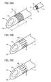
- FIG. 20A is a diagram showing a first example of a pattern of a concavo-convex processed portion of the implant placement device according to the seventh embodiment
- FIG. 20B is a pattern of a concavo-convex processed part of the implant placement device according to the seventh embodiment
- 20C is a diagram showing a second example of FIG. 20C
- FIG. 20C is a diagram showing a third example of the pattern of the concave-convex processed portion of the implant placement device according to the seventh embodiment.
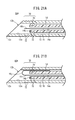
- FIG. 21A is a cross-sectional view of the implant placement device according to the first modification of the seventh embodiment
- FIG. 21B is a cross-sectional view of the implant placement device according to the second modification of the seventh embodiment.
- the implant placement device 10 is used when implanting an implant at a placement site with damaged tissue.
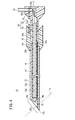
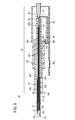
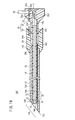
- the implantable body indwelling device 10 is housed in the tubular body 12 having a sharp tip portion 12 b, the elongated body 14 disposed inside the tubular body 12, and the elongated body 14. And an embedded body 16.
- the tubular body 12 is a substantially cylindrical member having an insertion hole 12a extending in the axial direction formed therein, and is elongated in the axial direction.
- the tubular body 12 is made of, for example, a metal such as stainless steel, and has a tip portion 12b having a tip surface 12d inclined with respect to the axial direction.
- a sharp needle tip 12c is formed at the tip end side of the tip surface 12d so that it can puncture the skin S or subcutaneous tissue.
- the tubular body 12 has an outer diameter of, for example, about 1.1 to 1.3 mm, and the inner insertion hole 12a has an inner diameter of, for example, about 0.8 to 1.0 mm.
- the length L1 from the needle tip 12c at the tip of the tubular body 12 to the base end 12e of the tubular body 12 can be set to, for example, about 100 mm.
- a tubular body hub 20 for operating the tubular body 12 is connected to the proximal end side of the tubular body 12.
- the tubular body hub 20 is made of, for example, resin and has an outer diameter larger than that of the tubular body 12 in order to facilitate the operation of the tubular body 12.
- a tubular body mounting portion 20b, an insertion hole 20c, and a housing portion 20a are provided in this order from the tip end side in the axial direction.
- the tubular body mounting portion 20b is an axially extending hole formed to have an inner diameter substantially the same as the outer diameter of the tubular body 12, and accommodates and holds the vicinity of the proximal end portion 12e of the tubular body 12.
- the tubular body 12 is joined to the tubular body hub 20 with an adhesive or the like at the tubular body mounting portion 20b.
- the insertion hole 20c is a hole extending in the axial direction and having an inner diameter substantially the same as the insertion hole 12a of the tubular body 12, and the elongated body 14 can be inserted therethrough.
- the housing portion 20a is a hole that extends in the axial direction, and is configured to be capable of housing a sliding portion 22c on the distal end side of an elongated body hub 22, which will be described later.
- the sliding portion 22c moves in the housing portion 20a while sliding on the inner surface of the housing portion 20a.
- a release pin 24 is formed on the base end side of the tubular body hub 20 so as to extend to the base end side.
- the elongated body 14 is a substantially cylindrical member having an embedded body accommodating hole 14a extending in the axial direction formed therein, and is elongated in the axial direction.
- the elongated body 14 is made of a metal such as stainless steel.
- the distal end portion 14b of the elongated body 14 is composed of a distal end surface that is substantially perpendicular to the axial direction, and is bluntly formed.
- the elongated body 14 is configured to be slidable in the axial direction along the insertion hole 12a of the tubular body 12. Further, the elongated body 14 is formed to be longer than the tubular body 12, and the tip portion 14b of the elongated body 14 can project to the tip side from the needle tip 12c of the tubular body 12.
- the elongated body 14 has an outer diameter of, for example, about 0.8 mm, and the embedded body housing hole 14a has an inner diameter of, for example, about 0.6 mm.
- the length L2 from the distal end portion 14b to the proximal end portion 14c of the elongated body 14 can be set to, for example, about 150 mm.
- an elongated body hub 22 for operating the elongated body 14 is provided on the proximal end side of the elongated body 14.
- the elongated body hub 22 includes an insertion hole 22a that accommodates and holds the vicinity of the proximal end portion 14c of the elongated body 14. That is, the elongated body hub 22 and the elongated body 14 are integrally joined at the insertion hole 22a.
- the distal end side of the elongated body hub 22 is provided with a cylindrical sliding portion 22c extending axially toward the distal end side, and the hub body 22d is provided at the proximal end side of the sliding portion 22c.
- the hub body 22d has a diameter larger than that of the sliding portion 22c.
- the length L3 from the tip portion 14b of the elongated body 14 to the base end portion of the elongated body hub 22 can be set to, for example, about 200 mm.
- the insertion hole 22a of the elongated body hub 22 is formed so as to penetrate through the elongated body hub 22 in the axial direction, and the fixing mechanism 17 is provided therein.
- the fixing mechanism 17 is configured to fix the embedded body 16 to the elongated body 14 by fixing the proximal end side of the embedded body 16.
- the fixing mechanism 17 of the present embodiment is formed in a clip shape that holds and holds the embedded body 16 by the biasing force of a spring (not shown).
- the hub body 22d is formed with an operation hole 22b extending in the radial direction.
- a removal operation pin 28 is inserted into the operation hole 22b.
- the tubular hub 20 and the elongated hub 22 are provided with a lock mechanism 25 to prevent the embedded body 16 from being unfixed at an unintended timing.
- the lock mechanism 25 includes a release pin 24 extending from the tubular body hub 20 toward the proximal end side, and a lock plate 26 provided on the elongated body hub 22.
- the lock plate 26 is configured to be movable in the axial direction along a guide hole 22e provided in the hub body 22d.
- the lock plate 26 is provided with an opening 26a capable of communicating with the operation hole 22b.
- FIG. 2A in the initial state, the lock plate 26 is arranged at a position that closes the operation hole 22b. Further, as shown in FIG.
- the embedded body 16 is accommodated in the embedded body accommodation hole 14 a of the elongated body 14.
- the implant 16 is a fibrous member that extends in the axial direction, and is a member that easily collects cells that regenerate the tissue when it is embedded in a damaged tissue in a living body. Examples of such a member include porous collagen fibers having innumerable micropores formed in the cross section.
- a thread-shaped body having an average diameter of about 0.4 mm and a length of 150 mm or more can be used.
- the outer diameter of the embedded body 16 is smaller than the inner diameter of the embedded body accommodation hole 14a of the elongated body 14, and the embedded body 16 is accommodated in the embedded body accommodation hole 14a in a state where no tension is applied to the embedded body 16.
- a locking portion 18 having a diameter larger than that of the main body of the embedded body 16 is attached to the tip side of the embedded body 16.
- the locking portion 18 is formed to have a larger diameter than the embedded body housing hole 14a of the elongated body 14. Therefore, the locking portion 18 can also be referred to as the expanded diameter portion.
- the locking portion 18 is locked to the distal end portion 14 b of the elongated body 14 and has a function as a cover of the elongated body 14. Therefore, the locking portion 18 is also called a cover portion. Further, when the locking portion 18 is separated from the elongated body 14 in the living tissue, the locking portion 18 engages in the living tissue and exerts a function of locking the implantable body 16 at a target site.
- the base end side of the embedded body 16 extends from the elongated body 14 to the base end side and is sandwiched by the fixing mechanism 17. That is, the embedded body 16 is fixed to the elongated body 14 by the fixing mechanism 17.
- the implant placement device 10 is configured as described above, and its operation will be described below.
- the implant placement device 10 can be used for a procedure to place the implant 16 near a lymph node having a damaged lymph vessel.
- Lymphatic vessel damage is caused by lymphadenectomy or radiation therapy when treating a tumor.
- lymph vessels When the lymph vessels are damaged and become dysfunctional, lymph may not flow properly and edema may occur.
- the implant 16 made of collagen fibers it is possible to induce cell proliferation and organization and promote regeneration of lymphatic vessels.
- a plurality of implants 16 are embedded in parallel in order to more reliably regenerate the lymphatic vessels.
- the operation of the implantable body indwelling device 10 will be described.
- the implant placement device 10 is punctured into the skin S near the placement site.
- the elongated body 14 is pulled into the insertion hole 12 a of the tubular body 12.
- the sharp needle tip 12c of the tubular body 12 allows the skin S to be easily punctured.
- the tubular body 12 is advanced in the subcutaneous tissue from the punctured site toward the indwelling site.
- the operation of advancing the tubular body 12 can be performed by the tubular body hub 20.
- the elongated body hub 22 is pushed in so that the elongated body 14 is projected from the tip of the tubular body 12 and placed.
- the elongated body 14 is advanced to the part. Since the tip portion 14b of the elongated body 14 is formed to be blunt, it is possible to suppress damage near the indwelling site.
- the embedded body 16 is transferred to the indwelling site while being covered with the elongated body 14. At this time, a load such as a pulling force does not act on the implant 16, so that it is possible to prevent the fine tissue of the implant 16 from being broken and the fixing property of cells to be lowered.
- the fixation of the embedded body 16 by the fixing mechanism 17 is released, and the embedded body indwelling device 10 including the elongated body 14 and the tubular body 12 is pulled out.
- the locking portion 18 at the tip of the implant 16 is pressed against the subcutaneous tissue, and thus is kept in a state of being engaged with the indwelling site.
- the embedded body 16 can be indwelled with a minimum load without exerting a tensile force on the embedded body 16.
- the implant 16 can be left in the target tissue while maintaining the fine structure of the implant 16.
- the implant placement device 10 and the implant 16 of the present embodiment have the following effects.
- the implantable device placement instrument 10 described above includes a tubular body 12 having a distal end portion 12b that can be inserted into a subcutaneous tissue and an insertion hole 12a that extends axially from the distal end portion 12b toward the proximal end side.
- the long embedded body 16 having the ability to promote tissue regeneration due to attachment of cells and the insertion hole 12a of the tubular body 12 are housed and moved along the insertion hole 12a of the tubular body 12 to move to the tubular body 12.
- the elongated body 14 that can protrude from the distal end portion 12b is provided, and the elongated body 14 moves the distal end portion of the embedded body 16 from the insertion hole 12a of the tubular body 12 as the elongated body 14 advances with respect to the tubular body 12. It is configured to be pushed out in the distal direction. As a result, the embedded body 16 can be transferred to the indwelling site while being accommodated in the elongated body 14, and a load such as a pulling force or the like can be prevented from acting on the embedded body 16. As a result, it is possible to protect the fine tissue of the implant 16 and improve the fixability of cells.
- a fixing mechanism 17 for detachably fixing the embedded body 16 to the elongated body 14 may be provided. As a result, the embedded body 16 can be removed from the elongated body 14 and embedded at a desired indwelling site.
- the distal end portion 12b of the tubular body 12 is sharply formed, and the distal end portion 14b of the elongated body 14 is bluntly formed. This can prevent damage to blood vessels, nerves, and the like when the tip portion 14b of the elongated body 14 is projected.
- the locking portion 18 may be formed to have a larger diameter than the main body of the implant 16. As a result, the locking portion 18 can be reliably locked at the indwelling site.
- the implant placement device 10 is not limited to the above-mentioned form.
- an elongated body fixing piece 27 for fixing the elongated body hub 22 to the tubular body hub 20 may be provided on the elongated body hub 22. ..
- the elongated body fixing piece 27 is provided with a protrusion 27a extending in the axial direction and protruding in the width direction.
- the tubular body hub 20 at a portion corresponding to the elongated body fixing piece 27 is provided with a hole 20f for accommodating the elongated body fixing piece 27.
- a recess 20g that engages with the protrusion 27a is provided on the side of the hole 20f.
- the protrusion 27a of the elongated body fixing piece 27 engages with the recessed portion 20g of the hole 20f, so that the elongated body is retained.
- the hub 22 is configured so as not to be displaced with respect to the tubular body hub 20. As a result, when releasing the fixation of the embedded body 16, it is possible to prevent the elongated body hub 22 from moving unintentionally and the detention site from being displaced.
- an embedded body indwelling device 10B according to Modification 2 has a different fixing mechanism 17 structure. That is, the embedded body indwelling device 10B includes a cap member 29 instead of the clip-shaped fixing mechanism 17.
- the cap member 29 includes a cap portion 29a inserted into the insertion hole 22a of the elongated hub 22 and a release piece 29b bent and extending from the cap portion 29a.
- the release piece 29b penetrates the hole 22f of the elongated body hub 22 and extends to the tip side of the hub body 22d.
- the base end side of the embedded body 16 is sandwiched and fixed to the cap portion 29a.
- an implantable body indwelling device 30 capable of transferring the implantable body 16 to the indwelling site by flexibly switching the tip portion between sharp and blunt depending on the site will be described.
- the same components as those in the implantable body indwelling instrument 10 of FIG. 1 are denoted by the same reference numerals, and detailed description thereof will be omitted.
- the embedded body indwelling device 30 of the present embodiment is capable of displacing the elongated body 14 in the axial direction freely.
- the moving mechanism 32 is provided.
- the moving mechanism 32 includes a tubular body hub 34 joined to the proximal end side of the tubular body 12, an elongated body hub 40 joined to the proximal end side of the elongated body 14, and an axial direction with respect to the tubular body hub 34. And a slider 36 that is slidably provided.
- the tubular body hub 34 includes a sliding portion 34e formed on the distal end side and a handle portion 48 formed on the proximal end side and having a diameter larger than that of the sliding portion 34e.
- the handle portion 48 is a portion for the user to operate the tubular body 12 by grasping it with a hand, and is formed in an outer shape that is easy to grasp.
- the elongated body hub 40 is housed inside the handle portion 48.
- the sliding portion 34e is a portion formed in a cylindrical shape, and is a portion on which the slider 36 mounted on the outer peripheral portion slides.
- a stopper 34d that prevents the slider 36 from falling off is provided at the tip of the sliding portion 34e.
- a tubular body mounting portion 34b, an insertion hole 34c, and an accommodating portion 34a are formed as holes penetrating in the axial direction in order from the tip end side in the axial direction.
- the proximal end side of the tubular body 12 is mounted and joined to the tubular body mounting portion 34b.
- the insertion hole 34c is a hole formed so that the elongated body 14 can be inserted therein.
- the accommodating portion 34a accommodates the main body of the elongated hub 40.
- the elongated body hub 40 is configured to be displaced while sliding in the housing portion 34a.
- a through hole 40a penetrating in the axial direction is provided inside the elongated body hub 40.
- the through hole 40a is formed to have an inner diameter substantially the same as the outer diameter of the elongated body 14, and accommodates and holds the proximal end side of the elongated body 14.
- a cap 46 is attached to the base end side of the through hole 40a.
- the cap 46 holds the embedded body 16 extending from the proximal end portion 14c of the elongated body 14 by sandwiching the proximal end side of the embedded body 16 with the through hole 40a. That is, in the present embodiment, the cap 46 constitutes a fixing mechanism that fixes the embedded body 16 to the elongated body 14.
- the cap 46 is formed so as to be elongated in the axial direction and project from the base end side of the handle portion 48 so as to be easily removable.
- the arm portion 42 extends radially outward from the base end side of the elongated body hub 40.
- An engagement portion 44 extends from the outer end of the arm portion 42 toward the tip end side in the axial direction.
- the engagement portion 44 includes a claw portion 44b that engages with the flange portion 36b of the slider 36.
- the engagement portion 44 is arranged to release the engagement with the flange portion 36b in a natural state where it is not subjected to stress, but remains in a position where it is blocked by the inner wall of the handle portion 48 and engages with the flange portion 36b. ..
- the flange portion 36b that engages with the claw portion 44b has an inclined portion 36c that is inclined radially outward of the flange portion 36b and toward the base end side.
- the claw portion 44b has an inclined portion 44c that is inclined inward in the radial direction and is inclined toward the tip side so as to engage with the inclined portion 36c of the flange portion 36b.
- a part of the handle portion 48 in the moving direction of the claw portion 44b is formed with a concave portion 48a formed in a concave shape on the inner peripheral surface side thereof.
- the slider 36 is a member formed in a substantially cylindrical shape, and its inner peripheral surface 36a is configured to be displaceable in the axial direction while sliding on the sliding portion 34e.
- a flange portion 36b having a large diameter is provided at the base end portion of the slider 36.
- the claw portion 44b of the engaging portion 44 extending from the elongated body hub 40 is engaged with the flange portion 36b. That is, the elongated body hub 40 is configured to be displaced in the axial direction by displacing the slider 36 in the axial direction.
- the slider 36 is configured so that it can be operated with the index finger when the handle portion 48 is grasped by the hand, and the axial position of the tip portion 14b of the elongated body 14 can be easily changed.
- the claw portion 44b of the elongated body hub 40 is caught by the flange portion 36b, and the claw portion 44b of the elongated body hub 40 is further caught by the concave portion 48a.
- the scale 14 is doubly locked by two hooks so as not to retract.
- the implant placement device 30 of the present embodiment is configured as described above, and its operation will be described below.
- the tubular body 12 of the implant placement device 30 is punctured into the skin S near the placement site.
- the distal end portion 14b of the elongated body 14 is in a state of being located at the second position closer to the base end side than the distal end portion 12b of the tubular body 12.
- the sharp needle tip 12c of the tubular body 12 is not obstructed by the distal end portion 14b of the elongated body 14 that is blunt, and the skin S can be easily punctured.
- the moving mechanism 32 is operated to displace the distal end portion 14b of the elongated body 14 to the first position projecting from the distal end of the tubular body 12 in accordance with the passing portion.
- the bluntly formed distal end portion 14b and the locking portion 18 of the elongated body 14 project, so that the blood vessel, nerve, and ligament can be passed through without being damaged.
- the slider 36 of the moving mechanism 32 is moved to the proximal end side as shown in FIG.
- the distal end portion 14b of 14 is displaced to the second position on the proximal side of the distal end portion 12b of the tubular body 12. This allows the needle tip 12c of the tubular body 12 to puncture and pass a hard fibrous tissue.
- the elongated body 14 is displaced between the second position in FIG. 10 and the first position in FIG. 11 while moving the implant placement device 30 to the placement site.
- the tip portion 14b of the elongated body 14 is arranged at the detention site of the implant body 16. Then, as shown in FIG. 12, the cap 46 is removed from the elongated body hub 40 to release the fixation of the embedded body 16. Next, the tubular body hub 34 is pulled to the proximal end side, and the operation for pulling out the embedded body placement instrument 30 from the placement site is performed. As a result, the embedded body 16 is placed in the predetermined placement site, and the implantation of the embedded body 16 is completed.
- the implant placement device 30 of the present embodiment has the following effects.
- the implantable body indwelling device 30 is provided on the proximal end side of the tubular body 12 and the elongated body 14, and includes a moving mechanism 32 for displacing the elongated body 14 in the axial direction.
- a first position in which the distal end portion 14b of the tubular body 12 is projected from the distal end portion 12b of the tubular body 12, and a second position in which the distal end portion 14b of the elongated body 14 is retracted to the proximal end side from the distal end portion 12b of the tubular body 12, Can be freely displaced. This allows the implantable device placement device 30 to be safely advanced without damaging blood vessels, nerves, ligaments, or the like while passing through the subcutaneous tissue.
- the embedded body indwelling device 50 does not have the locking portion 18 at the tip 16 h of the embedded body 16 accommodated in the elongated body 14, and thus the embedded body 16 is not provided.
- the front end 16h of the long body 14 projects from the front end portion 14b of the elongated body 14 by a predetermined length.
- Other configurations are the same as those of the implant placement device 10 in FIG. 1.
- the implant placement device 50 of the present embodiment can also transfer the implant 16 to the placement site with most of the implant 16 covered with the elongated body 14. Further, even if the locking portion 18 is not provided, the embedded body 16 can be left in the indwelling site by pulling out the tubular body 12 and the elongated body 14.
- the implantable body indwelling device 60 does not include the locking portion 18 at the tip portion 16i of the implantable body 16 that is housed in the elongated body 14, and thus the implantable body is retained.
- a tip portion 16i of 16 projects from the tip portion 14b of the elongated body 14 by a predetermined length.
- the tip portion 16i of the embedded body 16 is folded back toward the base end side at the folded portion 16j, and is arranged along the side surface of the elongated body 14. The rest of the configuration is the same as that of the implant placement device 10 in FIG. 1.
- the implant placement device 60 of the present embodiment can also transfer the implant 16 to the placement site while covering most of the implant 16 with the elongated body 14. Further, even if the locking portion 18 is not provided, the embedded body 16 can be left in the indwelling site by pulling out the tubular body 12 and the elongated body 14.
- the elongated body hub 40 projects toward the proximal end side of the handle portion 48 and extends, and is embedded in the proximal end portion of the elongated body hub 40.
- a fixing mechanism 51 for fixing the body 16 detachably is provided. It should be noted that in the implantable body placement instrument 30A of the present embodiment, the same components as those of the embedded body placement instrument 30 described with reference to FIGS. 9 to 12 are denoted by the same reference numerals, and detailed description thereof will be omitted. Omit it.
- an arm portion 42 extends radially outward from a side portion near the middle in the axial direction, and from the arm portion 42, a tip end side in the axial direction.
- the engaging portion 44 extends toward.
- a claw portion 44b that engages with the flange portion 36b of the slider 36 is provided at the tip of the engaging portion 44.
- an engaging protrusion 48b that biases the engaging portion 44 toward the axis is provided at a portion facing the engaging portion 44.
- the engagement protrusion 48b is formed by an inclination that gradually projects inward from the base end side toward the tip end side, and the end portion on the tip end side is formed substantially perpendicular to the axial direction.
- the elongate body hub 40 includes an extending portion 40b extending toward the base end side of the arm portion 42.
- the extending portion 40b is formed to have a length such that the base end side projects from the handle portion 48 even when the elongated body hub 40 is advanced with respect to the handle portion 48.
- a through hole 40a is also formed inside the extending portion 40b, and the embedded body 16 is disposed in the through hole 40a.
- a fixing mechanism 51 that detachably fixes the embedded body 16 is attached to the base end of the extending portion 40b.
- the fixing mechanism 51 includes a fitting member 52 that is mounted on the base end of the extending portion 40b from the outside, and a cap member 54 that is mounted on the fitting member 52.
- the fitting member 52 has a cylindrical shape and is joined to the outer peripheral portion of the extending portion 40b.
- a screw mechanism 52a is provided on the outer peripheral portion of the fitting member 52, and the cap member 54 is mounted by screwing from the outer peripheral side of the fitting member 52 via the screw mechanism 52a.
- the cap member 54 is rotatable around the axis along the screw mechanism 52a as shown by the arrow in the figure.
- a semicircular opening 52b is formed at the base end of the inner fitting member 52.
- a semicircular opening 54a is formed at the base end of the cap member 54.
- the embedded body 16 is arranged so as to pass through these openings 52b and 54a.
- the embedded body 16 is sandwiched between the fitting member 52 and the cap member 54. And is fixed to the elongated body hub 40. That is, the embedded body 16 is in a state of being fixed to the elongated body 14.
- the embedded body 16 when a part of the opening 52b of the fitting member 52 and a part of the opening 54a of the cap member 54 communicate with each other, the embedded body 16 is fixed in a semi-released state. In the semi-released state, the embedded body 16 can move in the axial direction while receiving frictional resistance from the openings 52b and 54a. Further, when rotated as shown in FIG. 16C, the opening 52b of the fitting member 52 and the opening 54a of the cap member 54 communicate with each other, and the embedded body 16 is completely released from the fixed state. In this case, the implant body 16 can be inserted without receiving the resistance of the openings 52b and 54a, and the implant body indwelling device 30A can be pulled out while leaving the implant body 16 at the indwelling site.
- the implantable body indwelling device 30A of the present embodiment has the following effects.
- the embedded body indwelling instrument 30A holds the elongated body 14 as a moving mechanism 32A for axially displacing the elongated body 14, and also an elongated body hub that accommodates the embedded body 16 in the through hole 40a therein.
- a handle portion 48 that accommodates the elongated body hub 40 so as to be displaceable in the axial direction
- a slider 36 that is slidably attached to the handle portion 48 in the axial direction
- a slider 36 that is slidably attached to the handle portion 48 in the axial direction
- a slider 36 and the elongated body hub 40.
- an engaging portion 44 for engaging with each other, the elongated body hub 40 extends toward the base end side from the handle portion 48, and the embedded body 16 can be detachably attached to the base end portion of the elongated body hub 40.
- a fixing mechanism 51 for fixing is provided. Thus, the fixed state of the embedded body 16 can be released by operating the fixing mechanism 51 on the proximal end
- the fixing mechanism 51 is mounted on the proximal end portion of the elongated body hub 40, and is fitted with the fitting member 52 having the opening 52b that passes through the embedded body 16.
- the cap member 54 is rotatably mounted on the mounting member 52 and has an opening 54a that can be communicated with the opening 52b by rotating the mounting member 52. Accordingly, by rotating the cap member 54, the openings 52b and 54a are communicated with each other or closed, so that the embedded body 16 can be switched between a fixed state and a released state.
- the engagement portion 44 is formed in a shape such that the engagement with the slider 36 is released in the state where no stress acts, and the engagement portion 44 is formed on the inner peripheral surface of the handle portion 48.
- An engagement protrusion 48b that deforms 44 in a direction in which it engages with the slider 36 may be provided.
- the engagement protrusion 48b may be configured to release the engagement between the engagement portion 44 and the slider 36 when the slider 36 is displaced to the tip. According to this structure, it is possible to prevent the position of the long body 14 from being inadvertently changed in the state where the long body 14 is projected.
- the implantable body placement instrument 30B of the present embodiment is different from the implantable body placement instrument 30A of FIG. Be different.
- the other points are the same as those of the implant placement device 30A.
- the same components as those in the embedded body indwelling instrument 30A are designated by the same reference numerals, and detailed description thereof will be omitted.
- the elongated body hub 40 includes an extending portion 40c protruding from the arm portion 42 and the engaging portion 44 toward the base end side.
- the extending portion 40c is formed in a tubular shape having a through hole 40a inside.
- the extending portion 40c of the present embodiment is formed shorter than the extending portion 40b of FIG. 15, and has a length that does not protrude from the handle portion 48.
- a fixing mechanism 61 is provided near the base end of the elongated body hub 40 including the extending portion 40c.
- the fixing mechanism 61 of this embodiment includes a release knob 62, a lock piece 64, and an end cap 66.
- the end cap 66 is inserted into and attached to the through hole 40a opened at the base end of the elongated body hub 40.
- the end cap 66 is provided with an insertion portion 66b which is shaped so as to close the lower half of the cross-section of the through hole 40a and which projects toward the axially distal end side. By inserting the insertion portion 66b into the through hole 40a, the end cap 66 is attached to the base end portion of the elongated body hub 40.
- a convex portion 66a is provided on the upper end portion of the insertion portion 66b of the end cap 66.
- the convex portion 66a projects from the upper end of the insertion portion 66b, and the embedded body 16 is arranged so as to pass over the convex portion 66a.
- the elongated body hub 40 is provided with a cutout portion 65 that accommodates the lock piece 64 slidably in the axial direction over a predetermined range from the base end portion, and the lock piece 64 is arranged in the cutout portion 65.
- a guide rail mechanism 65a is provided on a side portion of the cutout portion 65, and the lock piece 64 is guided by the guide rail mechanism 65a and slides in the axial direction.
- the lock piece 64 is a rod-shaped member that extends in the axial direction, and has a base end side protrusion 64 b that is engageable with the protrusion 66 a of the end cap 66 on the base end side. As shown in FIG.
- the release knob 62 is attached to the handle portion 48 in a state of being displaceable in the axial direction along a guide portion 48c formed by cutting the handle portion 48 in the axial direction into a groove shape.
- the release knob 62 is displaced toward the tip end side in the axial direction, the lock piece 64 moves toward the tip end side, and the engagement state between the base end side protrusion 64b of the lock piece 64 and the protrusion 66a of the end cap 66 is released.
- the embedded body 16 is released from the fixed state.
- the subcutaneous tissue of the living body is punctured with the slider 36 pulled toward the proximal end side.
- the slider 36 is moved to the distal end side, and the elongated body 14 is projected from the tubular body 12.
- the lock piece 64 and the release knob 62 also move to the tip side with the forward movement of the elongated body hub 40. Then, the release knob 62 is exposed to the outside of the handle portion 48 and becomes operable.
- the release knob 62 is moved toward the tip.
- the lock piece 64 moves toward the distal end side, the proximal end side protrusion 64b of the lock piece 64 is disengaged from the convex portion 66a of the end cap 66, and the embedded body 16 is fixed. Will be released.
- the implantable body 16 is placed by pulling out the implantable body placement device 30B.
- the implantable body indwelling device 30B of the present embodiment has the following effects.
- the embedded body indwelling device 30B is embedded by engaging the lock piece 64 accommodated in the elongated body hub 40 so as to be movable in the axial direction and the lock piece 64 attached to the proximal end side of the elongated body hub 40.
- An end cap 66 that holds the insert body 16 and a release knob 62 that releases the engagement state between the lock piece 64 and the end cap 66 by engaging the lock piece 64 and displacing the lock piece 64 toward the distal end side.
- a fixing mechanism 61 having With such a configuration, the fixed state of the embedded body 16 can be easily released by operating the release knob 62, and the operability is improved.
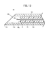
- the concavo-convex processed portion 70 is provided on the outer peripheral portion of the tubular body 12 near the tip portion 12b and the outer peripheral portion of the locking portion 18.
- the concave-convex processed portion 70 is composed of a plurality of grooves 72, and the grooves 72 are formed in an annular shape over the entire outer peripheral portion of the tubular body 12.
- the groove 72 may be composed of one or a plurality of spiral grooves.
- the range E in which the concavo-convex processed portion 70 is formed is at least 1 to 3 cm from the needle tip 12c of the tip portion 12b.
- a groove 72 is also formed on the outer peripheral portion of the locking portion 18 at the tip of the elongated body 14. ..
- the tubular body 12 and the locking portion 18 can be clearly seen using the ultrasonic diagnostic imaging apparatus, and the implantable body 16 can be accurately placed at the target site.
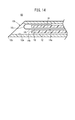
- the same effect can be obtained by forming an uneven processed portion 70A having a plurality of dimples 74 recessed in a spherical shape as shown in FIG. 20B instead of the uneven processed portion 70 including the groove 72 of FIG. 20A.
- the same effect can be obtained by providing the tubular body 12 and the locking portion 18 with the uneven processing portion 70B having a plurality of wedge-shaped recesses 76 as shown in FIG. 20C. ..
- the concavo-convex processed portion 70 of the present embodiment can be provided at the same site in the implant placement device 30 described with reference to FIGS. 9 to 12. Further, the concave-convex portion 70 of the present embodiment may be provided in the implant placement device 50 described with reference to FIG. 13 or the implant placement device 60 described with reference to FIG. 14.
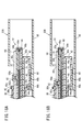
- An implantable body indwelling apparatus 50A according to the first modification shown in FIG. 21A is the embedded body indwelling apparatus 50 of FIG. 21A, the same components as those of the implant placement device 50 of FIG. 13 are denoted by the same reference numerals and detailed description thereof will be omitted.
- the concavo-convex processed portion 70 is provided on the outer peripheral portion of the tubular body 12 near the needle tip 12c. Further, in the embedded body indwelling device 50A, the concavo-convex processed portion 70 is also provided on the outer peripheral portion of the elongated body 14 near the tip portion 14b.
- the position of the distal end of the tubular body 12 can be clearly recognized by the ultrasonic diagnostic imaging apparatus when the implant placement device 50A is used. Further, since the concavo-convex processed portion 70 is provided in the vicinity of the tip portion 14b of the elongated body 14, when the elongated body 14 is projected from the tubular body 12, the position of the tip of the elongated body 14 can be detected by the ultrasonic imaging apparatus. Visible clearly.
- the embedded body indwelling instrument 60 shown in FIG. 14 is provided with an uneven processing portion 70.
- the tubular body 12 of the implantable body indwelling device 60A is provided with a concave-convex processed portion 70 on the outer peripheral portion near the tip portion 12b and on the outer peripheral portion near the tip portion 14b of the elongated body 14.
- the position of the tip of the tubular body 12 and the position of the tip of the elongated body 14 can be clearly recognized by the ultrasonic imaging apparatus when the implant placement device 60A is used. As a result, the embedded body 16 can be accurately placed at the target position.
Landscapes
- Health & Medical Sciences (AREA)
- Life Sciences & Earth Sciences (AREA)
- Engineering & Computer Science (AREA)
- Surgery (AREA)
- Public Health (AREA)
- General Health & Medical Sciences (AREA)
- Biomedical Technology (AREA)
- Heart & Thoracic Surgery (AREA)
- Veterinary Medicine (AREA)
- Animal Behavior & Ethology (AREA)
- Medical Informatics (AREA)
- Molecular Biology (AREA)
- Pathology (AREA)
- Nuclear Medicine, Radiotherapy & Molecular Imaging (AREA)
- Vascular Medicine (AREA)
- Anesthesiology (AREA)
- Hematology (AREA)
- Cardiology (AREA)
- Oral & Maxillofacial Surgery (AREA)
- Transplantation (AREA)
- Dermatology (AREA)
- Infusion, Injection, And Reservoir Apparatuses (AREA)
- Media Introduction/Drainage Providing Device (AREA)
- Prostheses (AREA)
Abstract
皮下組織に挿入可能な先端部(12b)と、先端部(12b)から基端側に向けて軸方向に貫通して延びる挿通孔(12a)と、を有する管状体(12)と、細胞が付着することで組織再生を促す能力を有する長尺な埋込体(16)と、管状体(12)の挿通孔(12a)に収納され、管状体(12)の挿通孔(12a)に沿って移動して管状体(12)の先端部(12b)から突出可能な長尺体(14)と、を備えた埋込体留置器具(10)において、長尺体(14)は、管状体(12)に対して前進することに伴って埋込体(16)の先端部を管状体(12)の挿通孔(12a)から先端方向に押し出すように構成されている。
Description
本発明は、皮膚から穿刺して体内に埋込体を留置する埋込体留置器具及び埋込体に関する。
機能が低下した組織を治療するために、当該部位に組織再生を促す埋込体を設置する治療法が種々提案されている。例えば、内部に無数の孔が形成された多孔質のコラーゲン繊維を損傷部位に埋入する方法が提案されている(特表2012-500203号公報)。このようなコラーゲン繊維を埋め込むと周囲に細胞が集まり、損傷組織の再生が促される効果がある。
一般的に、埋込体は、皮膚組織を切開して、損傷組織を露出させ、埋入するコラーゲン繊維を結紮クリップや組織用接着剤で損傷組織に固定する方法で埋め込まれている。しかし、このような手法では、侵襲が大きく患者への負担が大きいため、より負担の少ない手法が求められている。
そこで、本発明は、組織再生を促す能力を有する埋込体を損傷組織に留置するのに好適な埋込体留置器具及び埋込体を提供することを目的とする。
本発明の一観点は、皮下組織に挿入可能な先端部と、前記先端部から基端側に向けて軸方向に貫通して延びる挿通孔と、を有する管状体と、細胞が付着することで組織再生を促す能力を有する長尺な埋込体と、前記管状体の前記挿通孔に収納され、前記管状体の前記挿通孔に沿って移動して前記管状体の先端部から突出可能な長尺体と、を備え、前記長尺体は、前記管状体に対して前進することに伴って前記埋込体の先端部を前記管状体の前記挿通孔から先端方向に押し出す、埋込体留置器具にある。
本発明の別の一観点は、埋込体留置器具に使用される埋込体であって、前記埋込体の先端部は、前記長尺体の先端部から離間することで留置部位に係止可能な係止部を備える、埋込体にある。
本発明に係る埋込体留置器具によれば、埋込体を長尺体内に収容したまま留置部位に移送することができる。
以下、本発明の好適な実施形態を挙げ、添付の図面を参照して詳細に説明する。
(第1実施形態)
本実施形態に係る埋込体留置器具10は、損傷した組織のある留置部位に埋込体を埋め込む際に使用される。図1に示すように、埋込体留置器具10は、鋭利な先端部12bを有する管状体12と、管状体12の内部に配置された長尺体14と、長尺体14に収容された埋込体16とを備える。
本実施形態に係る埋込体留置器具10は、損傷した組織のある留置部位に埋込体を埋め込む際に使用される。図1に示すように、埋込体留置器具10は、鋭利な先端部12bを有する管状体12と、管状体12の内部に配置された長尺体14と、長尺体14に収容された埋込体16とを備える。
管状体12は、内部に軸方向に延びる挿通孔12aが形成された略円筒状の部材であり、軸方向に細長く延びて形成されている。管状体12は、例えば、ステンレス鋼等の金属よりなり、その先端部12bには、軸方向に対して傾斜した先端面12dが形成されている。その先端面12dの先端側の端部には、鋭利な針先12cが形成されており、皮膚Sや皮下組織に穿刺可能に形成されている。
管状体12は、例えば外径が1.1~1.3mm程度に形成されており、内部の挿通孔12aの内径は、例えば0.8~1.0mm程度に形成されている。管状体12の先端の針先12cから管状体12の基端部12eまでの長さL1は、例えば100mm程度とすることができる。
管状体12の基端側には、管状体12を操作するための管状体ハブ20が接続されている。管状体ハブ20は、例えば樹脂により形成されており、管状体12の操作を容易とするために管状体12よりも大きな外径に形成されている。管状体ハブ20の内部には、軸方向先端側から順に、管状体装着部20bと、挿通孔20cと、収容部20aとが設けられている。
管状体装着部20bは、管状体12の外径と略同じ内径に形成された軸方向に延在した孔であり、管状体12の基端部12e付近を収容して保持する。管状体12は、管状体装着部20bにおいて接着剤等により管状体ハブ20に接合されている。挿通孔20cは、管状体12の挿通孔12aと略同じ内径に形成された軸方向に延在する孔であり、長尺体14が挿通可能に構成されている。収容部20aは、軸方向に延在する孔であり、後述する長尺体ハブ22の先端側の摺動部22cを収容可能に構成されている。摺動部22cは、収容部20a内において収容部20aの内面と摺動しつつ移動する。また、管状体ハブ20の基端側には、解除ピン24が基端側に延び出て形成されている。
長尺体14は、内部に軸方向に延びる埋込体収容孔14aが形成された略円筒状の部材であり、軸方向に細長く延びて形成されている。長尺体14は、例えば、ステンレス鋼等の金属よりなる。長尺体14の先端部14bは、軸方向に略垂直な先端面で構成され、鈍に形成されている。長尺体14は、管状体12の挿通孔12aに沿って軸方向に摺動可能に構成されている。また、長尺体14は、管状体12よりも長く形成されており、その先端部14bは、管状体12の針先12cよりも先端側に突出可能となっている。
長尺体14は、外径が例えば0.8mm程度に形成され、埋込体収容孔14aの内径は例えば、0.6mm程度に形成されている。長尺体14の先端部14bから基端部14cまでの長さL2は、例えば150mm程度とすることができる。
長尺体14の基端側には、長尺体14を操作するための長尺体ハブ22が設けられている。長尺体ハブ22は、長尺体14の基端部14c付近を収容して保持する挿通孔22aを備えている。すなわち、長尺体ハブ22と長尺体14とは挿通孔22aにおいて一体的に接合されている。長尺体ハブ22の先端側は、軸方向に先端側に延び出た円筒状の摺動部22cを備え、その摺動部22cの基端側にハブ本体22dを備えている。長尺体14の操作を容易にするべく、ハブ本体22dは摺動部22cよりも大きな径に形成されている。長尺体14の先端部14bから長尺体ハブ22の基端部までの長さL3は、例えば200mm程度とすることができる。
長尺体ハブ22の挿通孔22aは、長尺体ハブ22の内部を軸方向に貫通して形成されており、その内部には固定機構17が設けられている。固定機構17は、埋込体16の基端側を固定することで、埋込体16を長尺体14に対して固定するように構成されている。本実施形態の固定機構17は、不図示のバネの付勢力で埋込体16を挟んで保持するクリップ状に形成されている。
図2Aに示すように、ハブ本体22dには、径方向に延びる操作孔22bが形成されている。その操作孔22bには、離脱操作ピン28が挿入されている。離脱操作ピン28を径方向内方(図の下方)に押し込むと、固定機構17による埋込体16の固定が解除されるように構成されている。
管状体ハブ20及び長尺体ハブ22には、意図しないタイミングで埋込体16の固定が解除されるのを防止するべく、ロック機構25が設けられている。ロック機構25は、管状体ハブ20から基端側に向けて延び出た解除ピン24と、長尺体ハブ22に設けられたロック板26とを備えている。このうち、ロック板26は、ハブ本体22dに設けられた案内孔22eに沿って軸方向に移動可能に構成されている。ロック板26には、操作孔22bと連通可能な開口部26aが設けられている。図2Aに示すように初期状態においては、ロック板26は、操作孔22bを塞ぐ位置に配置される。また、図2Bに示すように、長尺体ハブ22が管状体ハブ20に押し込まれると、ロック板26が解除ピン24によって基端側に変位して、ロック板26の開口部26aが操作孔22bと連通する。これにより、ロック機構25のロックが解除され、離脱操作ピン28で固定機構17を押圧可能となるように構成されている。すなわち、固定機構17による埋込体16の解除は、長尺体ハブ22を先端側に突出させることで可能となる。
図1に示すように埋込体16は、長尺体14の埋込体収容孔14a内に収容されている。埋込体16は、軸方向に長く延びた繊維状の部材であり、生体内において損傷した組織に埋め込んだ際に、組織を再生させる細胞が集まりやすい部材よりなる。このような部材としては、断面に無数の微細孔が形成された多孔質状のコラーゲン繊維が挙げられる。埋込体16は、例えば径の平均値が0.4mm程度で、長さが150mm以上の糸状のものを用いることができる。埋込体16の外径は、長尺体14の埋込体収容孔14aの内径よりも小さく、埋込体16に張力が掛からない状態で埋込体収容孔14a内に収容されている。
埋込体16の先端側には、埋込体16の本体よりも大きな径に形成された係止部18が取り付けられている。係止部18は、長尺体14の埋込体収容孔14aよりも大きな径に形成されている。したがって、係止部18は拡径部とも言い換えられる。係止部18は、長尺体14の先端部14bに係止されており、長尺体14のカバーとしての機能を有している。したがって、係止部18はカバー部とも言い換えられる。また、係止部18は、生体組織内において、長尺体14から離間すると、生体組織中に係合して埋込体16を目的部位に係止する機能を発揮する。
埋込体16の基端側は、長尺体14から基端側に延び出ており、固定機構17によって挟持されている。すなわち、埋込体16は、固定機構17によって長尺体14に固定されている。
本実施形態に係る埋込体留置器具10は、以上のように構成され、以下その作用について説明する。
図3に示すように、埋込体留置器具10は、損傷したリンパ管があるリンパ節付近に埋込体16を留置する手技に用いることができる。リンパ管の損傷は、腫瘍の治療の際のリンパ郭清や放射線治療等により生じる。リンパ管が損傷を受けて機能不全となると、リンパ液が正常に流れず浮腫を生ずることがある。このような機能不全を改善するために、コラーゲン繊維よりなる埋込体16を留置することで、細胞増殖性及び組織化を誘導して、リンパ管の再生を促すことができる。図示のように、リンパ管の再生をより確実に行うために、複数本の埋込体16が平行に埋め込まれる。以下、埋込体留置器具10の動作について説明する。
まず、図4に示すように、埋込体留置器具10を、留置部位の近くの皮膚Sに穿刺する。穿刺の際には、長尺体14を管状体12の挿通孔12aに引き込んだ状態で行う。管状体12の鋭利な針先12cにより、皮膚Sに穿刺を容易に行うことができる。その後、穿刺した部位から留置部位に向けて管状体12を皮下組織内で前進させる。管状体12を前進させる操作は、管状体ハブ20によって行うことができる。
次に、図5に示すように、管状体12が留置部位の近くの所定部位に到達したら、長尺体ハブ22を押し込むことにより、管状体12の先端から長尺体14を突出させて留置部位まで、長尺体14を前進させる。長尺体14の先端部14bは鈍に形成されているため、留置部位付近の損傷を抑制することができる。埋込体16は、長尺体14に覆われた状態で、留置部位にまで移送される。その際に、埋込体16に引っ張り力等の負荷が作用することがないため、埋込体16の微細組織が壊れて細胞の定着性が低下するのを防ぐことができる。
その後、図6に示すように、離脱操作ピン28を押し込むことで、固定機構17による埋込体16の固定を解除し、長尺体14及び管状体12を含む埋込体留置器具10を引き抜く操作を行う。その際に、埋込体16の先端の係止部18は、皮下組織に押圧されることで、留置部位に係合した状態に保たれる。埋込体16を残して、長尺体14及び管状体12を引き抜くことにより、埋込体16に引っ張り力を作用させることなく、最小限の負荷で埋込体16を留置させることができる。これにより、埋込体16の微細組織を維持したまま、埋込体16を目的とする組織に留置できる。以上により、埋込体16の留置が完了する。
本実施形態の埋込体留置器具10及び埋込体16は、以下の効果を奏する。
上記の埋込体留置器具10は、皮下組織に挿入可能な先端部12bと、先端部12bから基端側に向けて軸方向に貫通して延びる挿通孔12aと、を有する管状体12と、細胞が付着することで組織再生を促す能力を有する長尺な埋込体16と、管状体12の挿通孔12aに収納され、管状体12の挿通孔12aに沿って移動して管状体12の先端部12bから突出可能な長尺体14と、を備え、長尺体14は、管状体12に対して前進することに伴って埋込体16の先端部を管状体12の挿通孔12aから先端方向に押し出すように構成されている。これにより、埋込体16は、長尺体14に収容されたまま留置部位まで移送でき、埋込体16に引っ張り力等の負荷が作用するのを防止できる。その結果、埋込体16の微細組織を保護することができ、細胞の定着性を向上させることができる。
上記の埋込体留置器具10において、埋込体16を長尺体14に対して脱着自在に固定する固定機構17を設けてもよい。これにより、所望の留置部位にて埋込体16を長尺体14から外して埋め込むことができる。
上記の埋込体留置器具10において、管状体12の先端部12bが鋭利に形成され、長尺体14の先端部14bが鈍に形成されている。これにより、長尺体14の先端部14bを突出させた際に、血管や神経等の損傷を防ぐことができる。
上記の埋込体留置器具10において、埋込体16の先端部には、長尺体14の先端部14bから離間することで留置部位に係止可能な係止部18が設けられていてもよい。これにより、管状体12及び長尺体14を引き抜く際に埋込体16の変位を防いで、留置部位に確実に埋込体16を留置することができる。
上記の埋込体留置器具10において、係止部18は、埋込体16の本体よりも大きな径に形成されていてもよい。これにより、留置部位に係止部18を確実に係止できる。
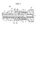
本実施形態に係る埋込体留置器具10は上記の形態に限られるものではない。例えば、図7の変形例1の埋込体留置器具10Aに示すように、長尺体ハブ22を管状体ハブ20に固定する長尺体固定片27を長尺体ハブ22に設けてもよい。長尺体固定片27は、軸方向に延在するとともに、幅方向に突出した突起27aを備えている。この長尺体固定片27に対応する部分の管状体ハブ20には、長尺体固定片27を収容する孔部20fを備えている。
孔部20fの側部には、突起27aに係合する凹部20gが設けられている。埋込体留置器具10Aでは、長尺体ハブ22を管状体ハブ20に押し込んだ際に、長尺体固定片27の突起27aが孔部20fの凹部20gに係合することで、長尺体ハブ22が管状体ハブ20に対して変位しないように構成されている。これにより、埋込体16の固定を解除する際に、長尺体ハブ22が意図せずに動いて、留置部位がずれるのを防止できる。
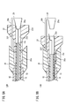
図8Aに示すように、変形例2の埋込体留置器具10Bは、固定機構17の構造が異なっている。すなわち、埋込体留置器具10Bは、クリップ状の固定機構17に変えて、キャップ部材29を備えている。
キャップ部材29は、長尺体ハブ22の挿通孔22aに挿入されたキャップ部29aと、キャップ部29aから屈曲して延び出た解除片29bとを備えている。解除片29bは、長尺体ハブ22の孔部22fを貫通してハブ本体22dの先端側に延び出ている。キャップ部29aには、埋込体16の基端側が挟み込まれて固定されている。
図8Bに示すように、長尺体ハブ22を管状体ハブ20に押し込むと、解除片29bが管状体ハブ20に当接して停止することで、キャップ部29aが長尺体ハブ22の挿通孔22aから外れる。その結果、埋込体16の固定が解除される。
(第2実施形態)
ところで、損傷した組織に埋込体16を移送する際に、硬い線維組織を通過する必要がある場合がある。また、皮下組織を通過中に、血管や、神経や人体等の損傷させたくない組織の近傍を通過させたい場合もある。そこで、本実施形態では、部位に応じて先端部を鋭利と鈍とを柔軟に切り換えて埋込体16を留置部位に移送できる埋込体留置器具30について説明する。なお、埋込体留置器具30において、図1の埋込体留置器具10と同様の構成については、同一符号を付してその詳細な説明は省略する。
ところで、損傷した組織に埋込体16を移送する際に、硬い線維組織を通過する必要がある場合がある。また、皮下組織を通過中に、血管や、神経や人体等の損傷させたくない組織の近傍を通過させたい場合もある。そこで、本実施形態では、部位に応じて先端部を鋭利と鈍とを柔軟に切り換えて埋込体16を留置部位に移送できる埋込体留置器具30について説明する。なお、埋込体留置器具30において、図1の埋込体留置器具10と同様の構成については、同一符号を付してその詳細な説明は省略する。
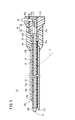
図9に示すように本実施形態の埋込体留置器具30は、管状体12と、長尺体14と、埋込体16と、に加えて、長尺体14を軸方向に自在に変位させる移動機構32を備えている。
移動機構32は、管状体12の基端側に接合された管状体ハブ34と、長尺体14の基端側に接合された長尺体ハブ40と、管状体ハブ34に対して軸方向に摺動自在に設けられたスライダー36とを備えている。このうち、管状体ハブ34は、先端側に形成された摺動部34eと、基端側に形成され、摺動部34eよりも大きな径に形成されたハンドル部48とを備えている。ハンドル部48は、使用者が手で握って管状体12を操作するための部位であり握りやすい外形に形成されている。ハンドル部48の内部には、長尺体ハブ40が収容されている。
摺動部34eは、円筒状に形成された部位であり、その外周部に装着されたスライダー36が摺動する部分となっている。摺動部34eの先端にはスライダー36の脱落を防ぐストッパ34dが設けられている。摺動部34eの内部には、軸方向先端側から順に、軸方向に貫通する孔として、管状体装着部34bと、挿通孔34cと、収容部34aとが形成されている。管状体装着部34bには管状体12の基端側が装着されて接合されている。挿通孔34cは、長尺体14が挿通自在に形成された孔である。収容部34aは、長尺体ハブ40の本体が収容される。本実施形態では、長尺体ハブ40が収容部34a内を摺動しつつ変位するように構成されている。
長尺体ハブ40の内部には、軸方向に貫通する貫通孔40aが設けられている。貫通孔40aは、長尺体14の外径と略同じ内径に形成されており、長尺体14の基端側を収容して保持している。また、貫通孔40aの基端側には、キャップ46が装着されている。キャップ46は、長尺体14の基端部14cから延び出た埋込体16の基端側を、貫通孔40aとの間で挟みこむことで保持する。すなわち、本実施形態では、キャップ46が埋込体16を長尺体14に固定する固定機構を構成している。なお、キャップ46は、容易に取り外し可能とするべく、軸方向に細長く延びてハンドル部48の基端側から突出するように形成されている。
長尺体ハブ40の基端側からは、腕部42が径方向外方に延び出ている。その腕部42の外方の端部からは、軸方向先端側に向けて係合部44が延び出ている。係合部44は、スライダー36のフランジ部36bに係合する爪部44bを備えている。係合部44は、応力を受けない自然状態において、フランジ部36bとの係合を解除する配置であるが、ハンドル部48の内壁に遮られてフランジ部36bと係合する位置に留まっている。爪部44bと係合するフランジ部36bは、フランジ部36bの径方向外側、且つ、基端側に傾斜する傾斜部36cを有している。爪部44bは、フランジ部36bの傾斜部36cに係合するように、径方向内側、且つ、先端側に傾斜する傾斜部44cを有している。
ハンドル部48の爪部44bの移動方向の一部分には、その内周面側に凹状に形成された凹部48aが形成されている。スライダー36及び係合部44を前進させると、係合部44の自由端側が凹部48aに入り、爪部44bが凹部48aに引っ掛かる。また、スライダー36を基端側に後退させると、爪部44bとフランジ部36bとが係合して、長尺体14が管状体12の内部に収納されるように構成されている。爪部44bの傾斜部44cがフランジ部36bの傾斜部36cと当接することで、腕部42が内方に引き上げられる。これにより、爪部44bの下側突出部と凹部48aとの係合が解除される。
スライダー36は、略円筒状に形成された部材であり、その内周面36aが摺動部34eに摺動しつつ軸方向に変位可能に構成されている。スライダー36の基端部には、径の大きなフランジ部36bが設けられている。このフランジ部36bには、長尺体ハブ40から延びる係合部44の爪部44bが係合している。すなわち、スライダー36を軸方向に変位させることで、長尺体ハブ40が軸方向に変位するように構成されている。スライダー36は、ハンドル部48を手で握った際に、人差指で操作することができ、長尺体14の先端部14bの軸方向の位置を容易に変えることができるように構成されている。スライダー36を前進させると、長尺体ハブ40の爪部44bは、フランジ部36bに引っ掛かった状態で、更に長尺体ハブ40の爪部44bは凹部48aにも引っ掛かることから、意図せず長尺体14が後退しないように2つの引っ掛かりにより二重にロックされる。
本実施形態の埋込体留置器具30は以上のように構成され、以下その作用について説明する。
まず、図10に示すように、埋込体留置器具30の管状体12を留置部位の近くの皮膚Sに穿刺する。この場合には、長尺体14の先端部14bは、管状体12の先端部12bよりも基端側の第2位置に位置した状態とする。これにより、管状体12の鋭利な針先12cが鈍に形成された長尺体14の先端部14bで妨げられることがなくなり、皮膚Sを容易に穿刺することができる。
次に、長尺体14を皮膚組織の内部で、留置部位に向けて前進させる。この場合において、通過する部位に応じて、図11に示すように、移動機構32を操作して長尺体14の先端部14bを管状体12の先端から突出した第1位置に変位させる。第1位置では、鈍に形成された長尺体14の先端部14b及び係止部18が突出するため、血管、神経及び靭帯を損傷させることなく、通過させることができる。
また、留置部位に向けて前進させる途中で、硬い線維組織を通過させる必要が生じた場合には、図10に示すように移動機構32のスライダー36を基端側に移動させて、長尺体14の先端部14bを管状体12の先端部12bよりも基端側の第2位置に変位させる。これにより、管状体12の針先12cで硬い線維組織を穿刺して通過させることができる。
上記のようにして、長尺体14を図10の第2位置及び図11の第1位置とで変位させつつ埋込体留置器具30を留置部位に移動させる。
その後、長尺体14の先端部14bを埋込体16の留置部位に配置する。そして、図12に示すように、キャップ46を長尺体ハブ40から取り外して、埋込体16の固定を解除する。次に、管状体ハブ34を基端側に引いて、埋込体留置器具30を留置部位から引き抜く操作を行う。これにより、埋込体16が所定の留置部位に留置されて、埋込体16の埋込が完了する。
本実施形態の埋込体留置器具30は、以下の効果を奏する。
埋込体留置器具30は、管状体12及び長尺体14の基端部側に設けられ、長尺体14を軸方向に変位させる移動機構32を備え、移動機構32は、長尺体14の先端部14bを管状体12の先端部12bよりも突出させる第1位置と、長尺体14の先端部14bを管状体12の先端部12bよりも基端側に後退させる第2位置と、に自在に変位させることができる。これにより、皮下組織を通過中に、血管、神経、及び靭帯等を傷つけずに、安全に埋込体留置器具30を進めることができる。
(第3実施形態)
図13に示すように、本実施形態の埋込体留置器具50は、長尺体14に収容される埋込体16の先端16hに係止部18が設けられておらず、埋込体16の先端16hが長尺体14の先端部14bから所定長さだけ突出している。その他の構成は、図1の埋込体留置器具10と同様である。
図13に示すように、本実施形態の埋込体留置器具50は、長尺体14に収容される埋込体16の先端16hに係止部18が設けられておらず、埋込体16の先端16hが長尺体14の先端部14bから所定長さだけ突出している。その他の構成は、図1の埋込体留置器具10と同様である。
本実施形態の埋込体留置器具50によっても、埋込体16の大部分を長尺体14で覆った状態で留置部位に移送することができる。また、係止部18を設けなくても、管状体12及び長尺体14を引き抜くことで、埋込体16を留置部位に留置することができる。
(第4実施形態)
図14に示すように、本実施形態の埋込体留置器具60は、長尺体14に収容される埋込体16の先端部16iに係止部18が設けられておらず、埋込体16の先端部16iが長尺体14の先端部14bから所定長さだけ突出する。本実施形態では、埋込体16の先端部16iは、折り返し部16jにおいて基端側に折り返されており、長尺体14の側面に沿うようにして配置される。なお、その他の構成は、図1の埋込体留置器具10と同様である。
図14に示すように、本実施形態の埋込体留置器具60は、長尺体14に収容される埋込体16の先端部16iに係止部18が設けられておらず、埋込体16の先端部16iが長尺体14の先端部14bから所定長さだけ突出する。本実施形態では、埋込体16の先端部16iは、折り返し部16jにおいて基端側に折り返されており、長尺体14の側面に沿うようにして配置される。なお、その他の構成は、図1の埋込体留置器具10と同様である。
本実施形態の埋込体留置器具60によっても、埋込体16の大部分を長尺体14で覆った状態で留置部位に移送することができる。また、係止部18を設けなくても、管状体12及び長尺体14を引き抜くことで、埋込体16を留置部位に留置することができる。
(第5実施形態)
図15に示すように、本実施形態の埋込体留置器具30Aは、長尺体ハブ40がハンドル部48の基端側に突出して延びるとともに、長尺体ハブ40の基端部に埋込体16を脱着自在に固定する固定機構51が設けられている。なお、本実施形態の埋込体留置器具30Aにおいて、図9~図12を参照しつつ説明した埋込体留置器具30と同様の構成には、同一の符号を付してその詳細な説明は省略する。
図15に示すように、本実施形態の埋込体留置器具30Aは、長尺体ハブ40がハンドル部48の基端側に突出して延びるとともに、長尺体ハブ40の基端部に埋込体16を脱着自在に固定する固定機構51が設けられている。なお、本実施形態の埋込体留置器具30Aにおいて、図9~図12を参照しつつ説明した埋込体留置器具30と同様の構成には、同一の符号を付してその詳細な説明は省略する。
図示のように本実施形態の長尺体ハブ40は、軸方向の中間付近の側部から腕部42が径方向外方に向けて延び出ており、その腕部42から、軸方向先端側に向けて係合部44が延び出ている。係合部44の先端には、スライダー36のフランジ部36bに係合する爪部44bが設けられている。
本実施形態のハンドル部48の内壁には、係合部44に対向する部分に、係合部44を軸寄りに付勢する係合突起48bが設けられている。係合突起48bは、基端側から先端側に向けて徐々に内方に突出する傾斜によって構成されるとともに、その先端側の端部は軸方向に略垂直に形成されている。スライダー36を先端側に移動させて爪部44bを係合突起48bよりも先端側に移動させると、係合部44が係合突起48bから外れ、爪部44bとフランジ部36bとの係合が解除されるように構成されている。これにより、長尺体14のみを前進させることが可能となる。なお、スライダー36を基端側に引くと、爪部44bとフランジ部36bとが再び係合して長尺体14が管状体12内に収納可能となる。
長尺体ハブ40は、腕部42よりも基端側に延び出た延在部40bを備えている。延在部40bは、長尺体ハブ40をハンドル部48に対して前進させた状態であっても、基端側がハンドル部48から突出する長さに形成されており、ハンドル部48の外に露出している。延在部40bの内部にも貫通孔40aが形成されており、その貫通孔40aに埋込体16が配設されている。また、延在部40bの基端部には、埋込体16を脱着自在に固定する固定機構51が取り付けられている。
固定機構51は、延在部40bの基端部に外側から装着される嵌装部材52と、嵌装部材52に装着されたキャップ部材54とを備えている。嵌装部材52は、円筒状に形成されており、延在部40bの外周部に接合されている。嵌装部材52の外周部には、ねじ機構52aが設けられており、キャップ部材54はねじ機構52aを介して嵌装部材52の外周側からねじ込んで装着される。
図16Aに示すように、キャップ部材54は、ねじ機構52aに沿って図の矢印に示すように軸周りに回動可能となっている。図16B及び図16Cに示すように、内側の嵌装部材52の基端部には、半円形の開口部52bが形成されている。また、キャップ部材54の基端部には半円形の開口部54aが形成されている。埋込体16は、これらの開口部52b、54aを通過するように配置されている。
図16Aのように、嵌装部材52の開口部52bとキャップ部材54の開口部54aとが互いに連通しない位置にある場合には、埋込体16が嵌装部材52及びキャップ部材54とに挟まれて長尺体ハブ40に固定される。すなわち、埋込体16は、長尺体14に対して固定された状態となる。
図16Bのように、嵌装部材52の開口部52bの一部とキャップ部材54の開口部54aの一部とが連通する状態では、埋込体16の固定が半解放状態となる。半解放状態では、埋込体16が開口部52b、54aから摩擦抵抗を受けつつ、軸方向に移動可能となる。更に、図16Cのように回転させると、嵌装部材52の開口部52bとキャップ部材54の開口部54aとが連通して、埋込体16が固定状態から完全に解放された状態となる。この場合には、埋込体16は開口部52b、54aの抵抗を受けることなく、挿通可能となり、埋込体16を留置部位に残して、埋込体留置器具30Aの引き抜きが可能となる。
本実施形態の埋込体留置器具30Aは以下の効果を奏する。
埋込体留置器具30Aは、長尺体14を軸方向に変位させる移動機構32Aとして、長尺体14を保持するとともに、内部の貫通孔40a内に埋込体16を収容する長尺体ハブ40と、長尺体ハブ40を軸方向に変位可能に収容するハンドル部48と、ハンドル部48に対して軸方向にスライド可能に装着されたスライダー36と、スライダー36と長尺体ハブ40とを係合させる係合部44と、を備え、長尺体ハブ40がハンドル部48よりも基端側に延び出るとともに、長尺体ハブ40の基端部に埋込体16を脱着自在に固定する固定機構51が設けられている。これにより、ハンドル部48の基端側の固定機構51を操作することで、埋込体16の固定状態の解放を行うことができる。
上記の埋込体留置器具30Aにおいて、固定機構51は、長尺体ハブ40の基端部に装着されるとともに、埋込体16を通過する開口部52bを備えた嵌装部材52と、嵌装部材52に回動自在に装着されるとともに、回動させることにより開口部52bに連通可能な開口部54aを有するキャップ部材54と、により構成されている。これにより、キャップ部材54を回動させることにより、開口部52b、54aを連通又は閉塞させることにより、埋込体16の固定状態と解放状態とを切り換えることができる。
上記の埋込体留置器具30Aにおいて、係合部44は、応力が作用しない状態でスライダー36との係合が解除される形状に形成されるとともに、ハンドル部48の内周面に係合部44をスライダー36と係合する方向に変形させる係合突起48bを備えていてもよい。この場合、係合突起48bは、スライダー36を先端に変位させた際に、係合部44とスライダー36との係合を解除するように構成してもよい。このように構成すると、長尺体14を突出させた状態において、不用意に長尺体14の位置が変動する不具合を防ぐことができる。
(第6実施形態)
図17に示すように、本実施形態の埋込体留置器具30Bは、埋込体16を脱着自在に固定する固定機構61を備えた移動機構32Bにおいて、図15の埋込体留置器具30Aと相違する。その他の点は、埋込体留置器具30Aと同様に構成されている。埋込体留置器具30Bにおいて、埋込体留置器具30Aと同様の構成には同一符号を付してその詳細な説明は省略する。
図17に示すように、本実施形態の埋込体留置器具30Bは、埋込体16を脱着自在に固定する固定機構61を備えた移動機構32Bにおいて、図15の埋込体留置器具30Aと相違する。その他の点は、埋込体留置器具30Aと同様に構成されている。埋込体留置器具30Bにおいて、埋込体留置器具30Aと同様の構成には同一符号を付してその詳細な説明は省略する。
埋込体留置器具30Bの移動機構32Bにおいて、長尺体ハブ40は、腕部42及び係合部44から基端側に突出した延在部40cを備えている。延在部40cは内側に貫通孔40aを有する筒状に形成されている。本実施形態の延在部40cは、図15の延在部40bよりも短く形成されており、ハンドル部48からは突出しない長さに形成されている。
延在部40cを含む長尺体ハブ40の基端部付近には、固定機構61が設けられている。本実施形態の固定機構61は、解除ノブ62と、ロック片64と、端部キャップ66とを備えている。このうち、端部キャップ66は、図18Aに示すように、長尺体ハブ40の基端部に開口した貫通孔40aに挿入されて装着されている。端部キャップ66は、貫通孔40aの断面の下側半分を閉塞する形状で軸方向先端側に突出した挿入部66bを備えている。挿入部66bが貫通孔40aに挿入されることで、端部キャップ66が長尺体ハブ40の基端部に装着されている。
また、端部キャップ66の挿入部66bの上端部には、凸部66aが設けられている。凸部66aは、挿入部66bの上端部から突出し、凸部66aの上を通過するように埋込体16が配設される。
長尺体ハブ40には、その基端部から所定の範囲にわたって、ロック片64を軸方向に摺動自在に収容する切欠部65が設けられており、その切欠部65にロック片64が配置されている。切欠部65の側部には、案内レール機構65aが設けられており、ロック片64はその案内レール機構65aによって案内されて軸方向に摺動する。ロック片64は、軸方向に長尺に延びる棒状部材であり、その基端側には、端部キャップ66の凸部66aに係合可能な基端側突起64bが設けられている。図17に示すように、ロック片64を基端側に変位させると、基端側突起64bが凸部66aに係合し、埋込体16を挟み込んで固定するように構成されている。また、ロック片64の先端側には、解除ノブ62と係合する先端側突起64aが外方に向けて突出して形成されている。先端側突起64aには、解除ノブ62の接続部62aが係合している。すなわち、ロック片64は、解除ノブ62と軸方向に一体的に変位するように構成されている。
解除ノブ62は、ハンドル部48を軸方向に溝状に切り欠いて形成された案内部48cに沿って軸方向に変位可能な状態でハンドル部48に装着されている。解除ノブ62を軸方向先端側に変位させると、ロック片64が先端側に移動し、ロック片64の基端側突起64bと端部キャップ66の凸部66aとの係合状態が解除されて、埋込体16の固定が解除されるように構成されている。
以下、本実施形態の埋込体留置器具30Bの作用について説明する。
図17に示すように、スライダー36を基端側に引いた状態で生体の皮下組織への穿刺が行われる。管状体12が目的位置まで到着すると、スライダー36を先端側に移動させて、長尺体14を管状体12から突出させる。これにより、図18Aに示すように、長尺体ハブ40の前方への移動に伴って、ロック片64及び解除ノブ62も先端側に移動する。そして、解除ノブ62がハンドル部48の外側に露出して操作可能な状態となる。
その後、解除ノブ62を先端方向に移動させる。これにより、図18Bに示すように、ロック片64が先端側に移動して、ロック片64の基端側突起64bが端部キャップ66の凸部66aから外れ、埋込体16の固定状態が解除される。その後、埋込体留置器具30Bを引き抜くことで、埋込体16が留置される。
本実施形態の埋込体留置器具30Bは以下の効果を奏する。
埋込体留置器具30Bは、長尺体ハブ40に軸方向に移動可能に収容されたロック片64と、長尺体ハブ40の基端側に装着されロック片64と係合することで埋込体16を保持する端部キャップ66と、ロック片64と係合してロック片64を先端側に変位させることでロック片64と端部キャップ66との係合状態を解除する解除ノブ62と、を有する固定機構61を備えている。このような構成により、解除ノブ62の操作で埋込体16の固定状態を容易に解除することができ、操作性が向上する。
(第7実施形態)
上記の諸実施形態に記載された埋込体留置器具10、10A、10B、30、30A、30Bを使用する場合には、超音波画像診断装置を用いて、管状体12、長尺体14及び係止部18の位置を確認しながら目的部位に正確に位置決めして用いられる。そこで、本実施形態では、超音波画像診断装置で管状体12、長尺体14及び係止部18の先端部の位置がより鮮明に映るように、超音波に対する反射率を高める加工を施す例について説明する。なお、本実施形態で説明する埋込体留置器具において、図1~図18Bを参照しつつ説明した構成部材と同一の構成部材については、同一符号を付してその詳細な説明は省略する。
上記の諸実施形態に記載された埋込体留置器具10、10A、10B、30、30A、30Bを使用する場合には、超音波画像診断装置を用いて、管状体12、長尺体14及び係止部18の位置を確認しながら目的部位に正確に位置決めして用いられる。そこで、本実施形態では、超音波画像診断装置で管状体12、長尺体14及び係止部18の先端部の位置がより鮮明に映るように、超音波に対する反射率を高める加工を施す例について説明する。なお、本実施形態で説明する埋込体留置器具において、図1~図18Bを参照しつつ説明した構成部材と同一の構成部材については、同一符号を付してその詳細な説明は省略する。
図19に示す埋込体留置器具10Cでは、先端部12b付近の管状体12の外周部と、係止部18の外周部とに、凹凸加工部70を設けている。凹凸加工部70は、図20Aに示すように、複数本の溝72よりなり、溝72は管状体12の外周部の全周に亘って環状に形成されている。なお、溝72は螺旋状に形成された1本又は複数本の溝で構成してもよい。管状体12において、凹凸加工部70を形成する範囲Eは、先端部12bの針先12cから少なくとも1~3cmとすることが好ましい。また、図20Aの部分拡大図に示すように、長尺体14の先端の係止部18の外周部にも、溝72が形成されている。
このように構成することにより、超音波画像診断装置を用いて、管状体12及び係止部18を鮮明に視認することができ、目的部位に正確に埋込体16を配置することができる。
なお、図20Aの溝72よりなる凹凸加工部70に代えて、図20Bに示すように、球面状に凹んだディンプル74を複数設けた凹凸加工部70Aを形成しても、同様の効果が得られる。また、図20Aの凹凸加工部70に代えて、図20Cに示すように、楔状凹部76を複数設けた凹凸加工部70Bを管状体12及び係止部18に設けても同様の効果が得られる。
本実施形態の凹凸加工部70は、図9~図12を参照しつつ説明した埋込体留置器具30にも同様の部位に設けることができる。また、本実施形態の凹凸加工部70は、図13を参照しつつ説明した埋込体留置器具50又は図14を参照しつつ説明した埋込体留置器具60に設けてもよい。
図21Aに示す変形例1に係る埋込体留置器具50Aは、図13の埋込体留置器具50に凹凸加工部70を設けたものである。なお、図21Aの埋込体留置器具50Aにおいて図13の埋込体留置器具50と同様の構成については、同一の符号を付してその詳細な説明は省略する。図21Aに示すように、埋込体留置器具50Aでは、管状体12の針先12c付近の外周部に凹凸加工部70を設けている。また、埋込体留置器具50Aでは、長尺体14の先端部14b付近の外周部にも凹凸加工部70を設けている。
上記のように構成することにより、埋込体留置器具50Aを使用する際に、管状体12の先端の位置を超音波画像診断装置で鮮明に視認できる。また、長尺体14の先端部14b付近に凹凸加工部70を有するため、管状体12から長尺体14を突出させた際に、長尺体14の先端の位置を超音波画像診断装置で鮮明に視認できる。
図21Bに示す変形例2に係る埋込体留置器具60Aでは、図14の埋込体留置器具60に凹凸加工部70を設けたものである。埋込体留置器具60Aの管状体12には、先端部12b付近の外周部及び長尺体14の先端部14b付近の外周部に凹凸加工部70が設けられている。本変形例2においても、埋込体留置器具60Aを使用する際に、管状体12の先端の位置及び、長尺体14の先端の位置を、超音波画像診断装置によって鮮明に視認できる。これにより、埋込体16を目的位置に正確に留置できる。
上記において、本発明について好適な実施形態を挙げて説明したが、本発明は前記実施形態に限定されるものではなく、本発明の趣旨を逸脱しない範囲において、種々の改変が可能なことは言うまでもない。
Claims (10)
- 皮下組織に挿入可能な先端部と、前記先端部から基端側に向けて軸方向に貫通して延びる挿通孔と、を有する管状体と、
細胞が付着することで組織再生を促す能力を有する長尺な埋込体と、
前記管状体の前記挿通孔に収納され、前記管状体の前記挿通孔に沿って移動して前記管状体の先端部から突出可能な長尺体と、
を備え、
前記長尺体は、前記管状体に対して前進することに伴って前記埋込体の先端部を前記管状体の前記挿通孔から先端方向に押し出す、埋込体留置器具。 - 請求項1記載の埋込体留置器具であって、前記埋込体を前記長尺体に対して脱着自在に固定する固定機構を備えた、埋込体留置器具。
- 請求項1又は2記載の埋込体留置器具であって、前記管状体の先端部が鋭利に形成され、前記長尺体の先端部が鈍に形成されている、埋込体留置器具。
- 請求項3記載の埋込体留置器具であって、更に、
前記管状体及び前記長尺体の基端部に設けられ、前記長尺体を軸方向に変位させる移動機構を備え、
前記移動機構は、前記長尺体の先端部を前記管状体の先端部よりも突出させる第1位置と、前記長尺体の先端部を前記管状体の先端部よりも基端側に後退させる第2位置と、に自在に変位させることができる、埋込体留置器具。 - 請求項1~4のいずれか1項に記載の埋込体留置器具であって、前記埋込体の先端部は、前記長尺体の先端部から離間することで留置部位に係止可能な係止部を備える、埋込体留置器具。
- 請求項5記載の埋込体留置器具であって、前記係止部は、前記埋込体の本体よりも大きな径に形成されてなる、埋込体留置器具。
- 請求項1~6のいずれか1項に記載の埋込体留置器具であって、前記埋込体は、先端側が前記長尺体の先端部から突出した状態で前記長尺体に収容されている、埋込体留置器具。
- 請求項1~6のいずれか1項に記載の埋込体留置器具であって、前記埋込体は、先端側が前記長尺体の先端部から突出するとともに、前記埋込体の先端部が基端側に折り返されて前記長尺体の側面に沿うように配置されている、埋込体留置器具。
- 請求項1~8のいずれか1項に記載の埋込体留置器具に使用される埋込体であって、
前記埋込体の先端部には、前記長尺体の先端部から離間することで留置部位に係止可能な係止部を備える、埋込体。 - 請求項9記載の埋込体であって、前記係止部は、前記長尺体の前記埋込体を収容する埋込体収容孔よりも径が大きく形成されてなる、埋込体。
Priority Applications (2)
| Application Number | Priority Date | Filing Date | Title |
|---|---|---|---|
| JP2020571170A JP7430653B2 (ja) | 2019-02-06 | 2020-01-31 | 埋込体留置器具及び埋込体 |
| US17/395,386 US20210361405A1 (en) | 2019-02-06 | 2021-08-05 | Implant insertion device and implant |
Applications Claiming Priority (2)
| Application Number | Priority Date | Filing Date | Title |
|---|---|---|---|
| JP2019-019456 | 2019-02-06 | ||
| JP2019019456 | 2019-02-06 |
Related Child Applications (1)
| Application Number | Title | Priority Date | Filing Date |
|---|---|---|---|
| US17/395,386 Continuation US20210361405A1 (en) | 2019-02-06 | 2021-08-05 | Implant insertion device and implant |
Publications (1)
| Publication Number | Publication Date |
|---|---|
| WO2020162368A1 true WO2020162368A1 (ja) | 2020-08-13 |
Family
ID=71947846
Family Applications (1)
| Application Number | Title | Priority Date | Filing Date |
|---|---|---|---|
| PCT/JP2020/003775 Ceased WO2020162368A1 (ja) | 2019-02-06 | 2020-01-31 | 埋込体留置器具及び埋込体 |
Country Status (3)
| Country | Link |
|---|---|
| US (1) | US20210361405A1 (ja) |
| JP (1) | JP7430653B2 (ja) |
| WO (1) | WO2020162368A1 (ja) |
Cited By (2)
| Publication number | Priority date | Publication date | Assignee | Title |
|---|---|---|---|---|
| JP2022090253A (ja) * | 2020-12-07 | 2022-06-17 | テルモ株式会社 | リンパ管新生誘導デバイス |
| WO2023100890A1 (ja) * | 2021-11-30 | 2023-06-08 | テルモ株式会社 | リンパ管新生誘導デバイス |
Citations (6)
| Publication number | Priority date | Publication date | Assignee | Title |
|---|---|---|---|---|
| US6162203A (en) * | 1999-01-11 | 2000-12-19 | Haaga; John R. | Cargo delivery needle |
| JP2001518343A (ja) * | 1997-10-02 | 2001-10-16 | ボストン サイエンティフィック リミテッド | 繊維を体内へと送達するためのデバイスおよび方法 |
| US20050096697A1 (en) * | 2003-11-04 | 2005-05-05 | Forsberg Andrew T. | Vascular insertion sheath with stiffened tip |
| KR20150107292A (ko) * | 2014-03-14 | 2015-09-23 | 홍종수 | 성형용 수술사를 구비한 성형수술용 바늘 |
| US20170049972A1 (en) * | 2015-08-20 | 2017-02-23 | Barbara Persons | Integrated needle and cannula for plastic surgery |
| KR101878258B1 (ko) * | 2018-01-11 | 2018-08-17 | 주식회사 오브이월드 | 의료용실 삽입기구 |
Family Cites Families (4)
| Publication number | Priority date | Publication date | Assignee | Title |
|---|---|---|---|---|
| US5053046A (en) * | 1988-08-22 | 1991-10-01 | Woodrow W. Janese | Dural sealing needle and method of use |
| US8157816B2 (en) * | 2007-08-31 | 2012-04-17 | Kimberly-Clark Worldwide, Inc. | Gastropexy kit |
| US20090182192A1 (en) * | 2008-01-14 | 2009-07-16 | Olympus Medical Systems Corp. | Treating tool for endoscope |
| US10178990B2 (en) * | 2012-12-05 | 2019-01-15 | Y. Jacobs Medical Inc. | Apparatus for inserting surgical thread, and surgical procedure kit for inserting surgical thread comprising same |
-
2020
- 2020-01-31 WO PCT/JP2020/003775 patent/WO2020162368A1/ja not_active Ceased
- 2020-01-31 JP JP2020571170A patent/JP7430653B2/ja active Active
-
2021
- 2021-08-05 US US17/395,386 patent/US20210361405A1/en not_active Abandoned
Patent Citations (6)
| Publication number | Priority date | Publication date | Assignee | Title |
|---|---|---|---|---|
| JP2001518343A (ja) * | 1997-10-02 | 2001-10-16 | ボストン サイエンティフィック リミテッド | 繊維を体内へと送達するためのデバイスおよび方法 |
| US6162203A (en) * | 1999-01-11 | 2000-12-19 | Haaga; John R. | Cargo delivery needle |
| US20050096697A1 (en) * | 2003-11-04 | 2005-05-05 | Forsberg Andrew T. | Vascular insertion sheath with stiffened tip |
| KR20150107292A (ko) * | 2014-03-14 | 2015-09-23 | 홍종수 | 성형용 수술사를 구비한 성형수술용 바늘 |
| US20170049972A1 (en) * | 2015-08-20 | 2017-02-23 | Barbara Persons | Integrated needle and cannula for plastic surgery |
| KR101878258B1 (ko) * | 2018-01-11 | 2018-08-17 | 주식회사 오브이월드 | 의료용실 삽입기구 |
Cited By (4)
| Publication number | Priority date | Publication date | Assignee | Title |
|---|---|---|---|---|
| JP2022090253A (ja) * | 2020-12-07 | 2022-06-17 | テルモ株式会社 | リンパ管新生誘導デバイス |
| JP2025100804A (ja) * | 2020-12-07 | 2025-07-03 | テルモ株式会社 | リンパ管新生誘導デバイス |
| US12349913B2 (en) | 2020-12-07 | 2025-07-08 | Terumo Kabushiki Kaisha | Lymphangiogenesis inducing device |
| WO2023100890A1 (ja) * | 2021-11-30 | 2023-06-08 | テルモ株式会社 | リンパ管新生誘導デバイス |
Also Published As
| Publication number | Publication date |
|---|---|
| JPWO2020162368A1 (ja) | 2021-12-02 |
| US20210361405A1 (en) | 2021-11-25 |
| JP7430653B2 (ja) | 2024-02-13 |
Similar Documents
| Publication | Publication Date | Title |
|---|---|---|
| EP3463121B1 (en) | Systems for insertion of implantable devices | |
| US6461366B1 (en) | Surgical device for connecting soft tissue | |
| US6080167A (en) | Anastomotic instrument | |
| JP5871284B2 (ja) | 交換式カートリッジを持つアンカー送出システム | |
| KR101547488B1 (ko) | 골반저 치료에 관련된 장치 | |
| JP4338521B2 (ja) | 医療用縫合装置 | |
| AU704186B2 (en) | Universal handle for medical instruments | |
| CN114027919A (zh) | 止血可重新加载的夹子释放机构 | |
| US20150230955A1 (en) | Deployment handle for a prosthesis delivery device | |
| WO2013142487A1 (en) | Suture cartridge and method of use thereof | |
| JP7837980B2 (ja) | インプラント送達デバイス | |
| WO1998046142A1 (en) | Needle assembly and method for passing suture | |
| WO1998046142A9 (en) | Needle assembly and method for passing suture | |
| KR20220104170A (ko) | 액세스 캐뉼러 전진을 위한 디바이스, 시스템, 및 방법 | |
| JP2007075613A (ja) | 生体組織の処置具カートリッジ | |
| JP2017521176A (ja) | カニューレ挿入用システム、方法および装置 | |
| CN106232025A (zh) | 线固定系统 | |
| JP7391081B2 (ja) | 埋込体留置器具 | |
| JP7430653B2 (ja) | 埋込体留置器具及び埋込体 | |
| JP2007536981A (ja) | 拡張蛇行静脈を治療する装置と方法 | |
| JP3187336B2 (ja) | 植毛器具及び植毛用組織装着治具 | |
| US11399943B2 (en) | Furlow insertion device | |
| CN119365127A (zh) | 用于插入式生理监测器注射器工具的保持铰链 | |
| JP7541935B2 (ja) | 操作デバイス及び埋込体留置具 | |
| KR20220091006A (ko) | 성형용 리프팅 부재 |
Legal Events
| Date | Code | Title | Description |
|---|---|---|---|
| 121 | Ep: the epo has been informed by wipo that ep was designated in this application |
Ref document number: 20752014 Country of ref document: EP Kind code of ref document: A1 |
|
| ENP | Entry into the national phase |
Ref document number: 2020571170 Country of ref document: JP Kind code of ref document: A |
|
| NENP | Non-entry into the national phase |
Ref country code: DE |
|
| 122 | Ep: pct application non-entry in european phase |
Ref document number: 20752014 Country of ref document: EP Kind code of ref document: A1 |