WO2020162250A1 - センサモジュール - Google Patents
センサモジュール Download PDFInfo
- Publication number
- WO2020162250A1 WO2020162250A1 PCT/JP2020/002748 JP2020002748W WO2020162250A1 WO 2020162250 A1 WO2020162250 A1 WO 2020162250A1 JP 2020002748 W JP2020002748 W JP 2020002748W WO 2020162250 A1 WO2020162250 A1 WO 2020162250A1
- Authority
- WO
- WIPO (PCT)
- Prior art keywords
- sensor module
- magnet
- housing
- magnets
- module according
- Prior art date
- Legal status (The legal status is an assumption and is not a legal conclusion. Google has not performed a legal analysis and makes no representation as to the accuracy of the status listed.)
- Ceased
Links
Images








Classifications
-
- G—PHYSICS
- G01—MEASURING; TESTING
- G01D—MEASURING NOT SPECIALLY ADAPTED FOR A SPECIFIC VARIABLE; ARRANGEMENTS FOR MEASURING TWO OR MORE VARIABLES NOT COVERED IN A SINGLE OTHER SUBCLASS; TARIFF METERING APPARATUS; MEASURING OR TESTING NOT OTHERWISE PROVIDED FOR
- G01D11/00—Component parts of measuring arrangements not specially adapted for a specific variable
- G01D11/30—Supports specially adapted for an instrument; Supports specially adapted for a set of instruments
-
- H—ELECTRICITY
- H01—ELECTRIC ELEMENTS
- H01F—MAGNETS; INDUCTANCES; TRANSFORMERS; SELECTION OF MATERIALS FOR THEIR MAGNETIC PROPERTIES
- H01F7/00—Magnets
- H01F7/02—Permanent magnets [PM]
Definitions
- the present disclosure relates to a sensor module.
- Patent Document 1 discloses a method of fixing a fixing plate using two magnets. According to Patent Document 1, two magnets are placed in the recesses of the fixed plate that are spaced apart, and the magnet is sealed to the fixed plate with double-sided tape.
- a sensor module includes a sensor unit, a housing that has an adhesive surface that adheres to an object to be attached, accommodates the sensor unit, and a first magnet that is adhered to the housing.
- the magnetic force between the first magnet and the attachment target is stronger than the adhesive force between the housing and the first magnet.
- FIG. 1 is a schematic perspective view of the sensor module according to the first embodiment.
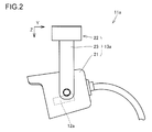
- FIG. 2 is a schematic side view of the sensor module according to the first embodiment.
- FIG. 3 is a schematic cross-sectional view of a second portion included in the housing.
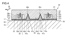
- FIG. 4 is a schematic cross-sectional view showing a state in which the sensor module is provisionally attached to the attachment target.
- FIG. 5 is a schematic cross-sectional view showing a state in which the second portion is once removed.
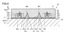
- FIG. 6 is a schematic cross-sectional view of the second portion after being attached to the attachment target.
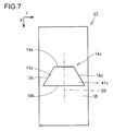
- FIG. 7 is a schematic plan view showing a state in which the second portion of the sensor module according to the second embodiment is viewed two-dimensionally from a direction perpendicular to the bonding surface.
- FIG. 1 is a schematic perspective view of the sensor module according to the first embodiment.
- FIG. 2 is a schematic side view of the sensor module according to the first embodiment.
- FIG. 3 is a schematic cross-sectional
- FIG. 8 is a schematic plan view showing a state in which the second portion of the sensor module according to the third embodiment is viewed two-dimensionally from a direction perpendicular to the bonding surface.
- FIG. 9 is a schematic plan view showing a state in which the second portion of the sensor module according to the fourth embodiment is viewed two-dimensionally from a direction perpendicular to the bonding surface.
- FIG. 10 is a schematic plan view showing a state in which the second portion of the sensor module according to the fifth embodiment is viewed two-dimensionally from a direction perpendicular to the bonding surface.
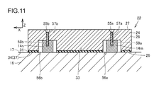
- FIG. 11 is a schematic cross-sectional view of the second portion of the sensor module according to the sixth embodiment after it is attached to the attachment target.
- FIG. 12 is a schematic cross-sectional view of the second portion of the sensor module according to the sixth embodiment before it is attached to the attachment target.
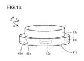
- FIG. 13 is a schematic perspective view showing a housing and a first magnet included in the sensor module according to the seventh embodiment.
- FIG. 14 is a schematic plan view showing a housing and a first magnet included in the sensor module according to the seventh embodiment.
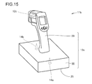
- FIG. 15 is a schematic perspective view of the sensor module according to the eighth embodiment.
- FIG. 16 is a schematic perspective view of the sensor module according to the ninth embodiment.
- Patent Document 1 discloses a fixing plate for adhering an article. When the sensor is attached to the attachment target, it is necessary to easily adjust the attachment position. Further, when the sensor is removed from the adjusted mounting position, it is required to accurately mount the sensor at the adjusted mounting position again.
- one of the objectives is to provide a sensor module that can easily adjust the mounting position and can be accurately mounted at the adjusted mounting position.
- the mounting position can be easily adjusted, and the sensor module can be accurately mounted at the adjusted mounting position.
- a sensor module includes a sensor unit, a housing that has an adhesive surface that adheres to an attachment target, and that houses the sensor unit, and a first magnet that is adhered to the housing.
- the magnetic force between the first magnet and the attachment target is stronger than the adhesive force between the housing and the first magnet.
- the sensor module includes the first magnet having the above configuration.
- the sensor module can be attached to the attachment target by the following procedure, for example.
- that the magnetic force between the first magnet and the attachment target is stronger than the adhesive force between the casing and the first magnet means that the casing to which the first magnet is attached is brought into contact with the attachment target. After that, when the mounting object is separated from the housing, the first magnet is separated from the housing and adheres to the mounting object by magnetic force.
- the sensor module attaches the sensor module at a predetermined position on the attachment target. After that, the sensor section detects information. Next, the mounting position is changed and the sensor module is mounted. After that, the sensor section detects the information again. By repeating this, the mounting position is adjusted to determine the optimum mounting position. After finishing the adjustment, remove the chassis at the adjusted mounting position. At this time, since the magnetic force between the first magnet and the attachment target is stronger than the adhesive force between the casing and the first magnet, the first magnet is detached from the casing and adhered to the attachment target by the magnetic force. It can be in a state.
- the first magnet Since the first magnet is in a state of being adhered to the adjusted mounting position, the first magnet can be accurately mounted at the adjusted mounting position when the housing is mounted on the mounting target. Therefore, according to the sensor module, the mounting position can be easily adjusted, and the sensor module can be accurately mounted at the adjusted mounting position.
- the sensor module can be fixed to the attachment target by, for example, applying an adhesive to the adhesive surface and then reattaching it to the attachment target in the case that has been removed. That is, the sensor module can be attached to the adjusted attachment position for a long period of time while suppressing the deviation from the adjusted attachment position.
- the first magnet may be exposed in the bonding surface in a plan view as seen from a direction perpendicular to the bonding surface. By doing so, the first magnet is easily separated from the housing, and the state in which the first magnet is adhered to the attachment target is easily obtained. Therefore, the mounting position can be adjusted more easily.
- the housing may further include an adhesive portion having a surface that constitutes an adhesive surface and having adhesiveness, and a release sheet that covers the adhesive portion and can be peeled from the adhesive portion.
- the housing may include a first recess having an opening on the adhesive surface.
- the first magnet may be arranged in the first recess.
- the wall surface surrounding the first recess may have a shape that follows the outer shape of the first magnet facing the wall surface.
- the number of symmetry axes of the outer shape of the first magnet in plan view seen from the direction perpendicular to the bonding surface may be 1 or less.
- the mounting direction when mounting on the mounting target is important.
- a plurality of first magnets may be provided.
- the first magnets can be bonded to at least two positions on the surface of the attachment target. Therefore, it is easy to attach the housing to the adjusted attachment position.
- the sensor module may include at least two first magnets having different outer shapes. By doing so, it is possible to uniquely determine the orientation of the housing when the housing is removed and then attached again. Therefore, it is possible to reduce the risk of mistaking the orientation of the housing when mounting the housing.
- the sensor module may include three or more first magnets.
- the number of symmetry axes of one figure constituted by line segments connecting the respective centers of gravity of the three or more first magnets is It may be 1 or less.
- the sensor module may include two first magnets. Make sure that the two first magnets are not point-symmetric with respect to the midpoint of the line segment that connects the centers of gravity of the two first magnets in plan view when the two first magnets are viewed in a direction perpendicular to the bonding surface. May be. By doing so, it is possible to uniquely determine the orientation of the housing when the housing is removed and then attached again. Therefore, it is possible to reduce the risk of mistaking the orientation of the housing when mounting the housing.
- the first magnet may be fixed by a screw that can release the fixation of the first magnet to the housing. By doing so, it is possible to reliably prevent the first magnet from falling out of the housing before the sensor module is attached to the attachment target. Further, when the first magnet is detached after adjusting the mounting position, the first magnet can be reliably adhered to the adjusted mounting position by releasing the fixing of the first magnet to the housing with the screw. Furthermore, if the first magnet is fixed to the housing with a screw after the housing is mounted on the mounting object again, the magnetic force of the first magnet can bond the sensor module to the mounting object. Therefore, it is possible to more reliably suppress the displacement from the attachment position over a long period of time.
- the sensor module may further include a second magnet that is fixed to the housing and that adheres the housing to the object to be attached by magnetic force. By providing such a second magnet, the housing can be more firmly adhered to the attachment target by the magnetic force of the second magnet.
- the second magnet may be arranged in a housing space formed in the housing. By doing so, the second magnet can be arranged at an appropriate position in the housing.
- the virtual plane including the adhesive surface may be located apart from the second magnet. By doing so, it is possible to avoid concentration of the adhesive force at the position where the second magnet is arranged. Therefore, it is possible to more reliably suppress the displacement from the attachment position over a long period of time.
- the material to be attached may be steel. Since steel has ferromagnetism, it becomes easy to bond it by magnetic force.
- FIG. 1 is a schematic perspective view of the sensor module according to the first embodiment.
- FIG. 2 is a schematic side view of the sensor module according to the first embodiment.
- the sensor module 11a according to the first embodiment is, for example, a camera that captures an image of a separated region.
- the sensor module 11a includes a sensor unit 12a, a housing 13a, and a plurality of first magnets 14a and 14b. In this embodiment, the sensor module 11a includes two first magnets 14a and 14b. Note that, in FIGS. 1 and 2, the sensor unit 12a is schematically illustrated by a broken line.
- the sensor unit 12a includes, for example, an image sensor.
- the housing 13 a has a lens 15 and has a first portion 21 that houses the sensor portion 12 a, a second portion 22 to which the two first magnets 14 a and 14 b are bonded, a first portion 21 and a second portion 22. And a third portion 23 that connects and.
- FIG. 3 is a schematic sectional view of the second portion 22 included in the housing 13a.
- the second portion 22 is arranged so as to cover the rectangular parallelepiped main body portion 24 and the first surface 26 of the main body portion 24, and covers the adhesive portion 31 having adhesiveness and the adhesive portion 31.
- a release sheet 32 that can be released from the adhesive portion 31.
- the main body portion 24 intersects with the first surface 26, the second surface 27 that is spaced apart from the first surface 26 and arranged parallel to the first surface 26, and both the first surface 26 and the second surface 27.
- a side wall surface 28 is orthogonal to both the first surface 26 and the second surface.
- the surface of the attachment target to which the sensor module 11a is attached is also flat.
- the material of the attachment target is a ferromagnetic material such as steel. Since steel has ferromagnetism, it becomes easy to bond it by magnetic force. A predetermined member is attached to the attachment target by magnetic force.
- the adhesive portion 31 is layered and is arranged so that the one main surface 33 and the first surface 26 are in contact with each other.
- the one main surface 33 and the first surface 26 are bonded.
- the release sheet 32 is arranged so that one main surface 35 and the other main surface 34 of the adhesive section 31 are in contact with each other.
- the other main surface 36 of the release sheet 32 is exposed.
- the other main surface 34 of the adhesive portion 31 is covered with the release sheet 32.
- the adhesive portion 31 includes the other main surface 34 that constitutes the adhesive surface 37.
- the other main surface 34 of the adhesive portion 31 is an adhesive surface 37. That is, the second portion 22 of the housing 13a has an adhesive surface 37 that adheres to the attachment target. Examples of members that form the adhesive portion 31 and the release sheet 32 include double-sided tape.
- the adhesive portion 31 and the release sheet 32 are arranged so as to cover the entire first surface 26 except for the regions where the first recesses 46a and 46b described later are formed.
- the sensor module 11a is attached to the attachment target while being in contact with the adhesive surface 37. Specifically, the sensor module 11a is attached to the attachment target after the release sheet 32 is peeled off so that the surface of the attachment target and the other main surface 34 of the adhesive portion 31, which is the adhesive surface 37, come into contact with each other.
- the first magnet 14a has a conical shape.
- the first magnet 14a has a bottom surface 41a and a conical surface 42a.
- the first magnet 14b has the same shape as the first magnet 14a.
- the first magnet 14b has a bottom surface 41b and a conical surface 42b.
- the first magnets 14a and 14b are, for example, neodymium magnets.
- the two first recesses 46a and 46b are formed in the second portion 22.
- the first recesses 46a and 46b have a shape corresponding to the first magnets 14a and 14b, that is, a conical shape.
- the first recesses 46a and 46b respectively penetrate the adhesive portion 31 and the release sheet 32 in the thickness direction.
- the conical first recesses 46 a and 46 b are formed such that their vertices are located inside the main body 24 and their bottom surfaces are along the first surface 26.
- Each of the first recesses 46a and 46b has an opening in the bonding surface 37.
- the first recesses 46a and 46b are arranged at intervals in the X direction in FIG.
- the first recess 46a is surrounded by the wall surface 47a.
- the first recess 46b is surrounded by the wall surface 47b.
- the wall surface 47a surrounding the first recess 46a has a shape that follows the outer shape of the first magnet 14a that faces the wall surface 47a. Specifically, the wall surface 47a surrounding the first recess 46a has a conical surface shape along the conical surface 42a. The first magnet 14a is arranged in the first recess 46a. In this case, the conical surface 42a is bonded to the wall surface 47a.
- the bottom surface 41a is exposed in a plan view seen from a direction perpendicular to the bonding surface 37. In the present embodiment, the bottom surface 41a is exposed when viewed in the direction indicated by the arrow Z in FIG.
- the wall surface 47b surrounding the first recess 46b has a shape that follows the outer shape of the first magnet 14b facing the wall surface 47b. Specifically, the wall surface 47b surrounding the first recess 46b has a conical surface shape along the conical surface 42b. The first magnet 14b is arranged in the first recess 46b. In this case, the conical surface 42b is bonded to the wall surface 47b.
- the bottom surface 41b is exposed in a plan view seen from a direction perpendicular to the bonding surface 37. In the present embodiment, the bottom surface 41b is exposed when viewed in the direction indicated by the arrow Z in FIG.
- the conical surface 42a is bonded to the wall surface 47a with a comparatively weak adhesive force by the member having the adhesive property arranged on the wall surface 47a.
- the first magnet 14 a arranged in the first recess 46 a is bonded to the main body 24.
- the magnetic force between the first magnet 14a and the attachment target is stronger than the adhesive force between the housing 13a and the first magnet 14a. Therefore, when the ferromagnetic member is brought closer to the bottom surface 41a, the magnetic force releases the adhesion state between the housing 13a and the first magnet 14a, and the first magnet 14a adheres to the ferromagnetic member.
- the conical surface 42b is adhered to the wall surface 47b with a comparatively weak adhesive force by means of an adhesive member arranged on the wall surface 47b.
- the first magnet 14b arranged in the first recess 46b is bonded to the main body 24.
- the magnetic force between the first magnet 14b and the attachment target is stronger than the adhesive force between the housing 13a and the first magnet 14b. Therefore, when the ferromagnetic member is brought closer to the bottom surface 41b, the magnetic force releases the bonded state between the housing 13a and the first magnet 14b, and the first magnet 14b is bonded to the ferromagnetic member.
- the sensor module 11a includes two second magnets 51a and 51b.
- the second magnets 51a and 51b are fixed to the housing 13a and adhere to the housing 13a by magnetic force.
- the second magnet 51a has a cylindrical shape.
- the second magnet 51b has the same shape as the second magnet 51a.
- the two second magnets 51a and 51b are respectively fixed to the main body portion 24 included in the second portion 22 of the housing 13a.
- the main body 24 is formed with two second recesses 52a and 52b.
- the second recesses 52a and 52b have an opening in the first surface 26 and are cylindrically recessed so that the second magnet 51a can be housed therein.
- the second recess 52b has an opening in the first surface 26 and has a columnar recessed shape so that the second magnet 51b can be housed therein.
- the second magnets 51a and 51b are arranged in second recesses 52a and 52b, which are accommodation spaces formed in the main body 24, respectively.
- the openings of the second recesses 52a and 52b are covered with the adhesive portion 31 and the release sheet 32.
- the second magnet 51a is formed with a through hole 53a penetrating in the direction along the central axis of the second magnet 51a.
- the second magnet 51b is formed with a through hole 53b penetrating in a direction along the central axis of the second magnet 51b.
- the second magnet 51a is fixed to the main body 24 by inserting a screw 54a into the through hole 53a.
- the second magnet 51b is fixed to the main body 24 by inserting a screw 54b into the through hole 53b.
- the virtual plane 38 including the adhesion surface 37 is located away from the second magnets 51a and 51b.
- the virtual plane 38 is shown by a dashed line in FIG.
- a gap L is formed between the second magnet 51a and one main surface 33 of the adhesive portion 31 located on the side where the second magnet 51a is arranged with respect to the virtual plane 38. The same applies to the second magnet 51b.
- the mounting position can be easily adjusted, and the mounting can be accurately performed at the adjusted mounting position. This will be described.
- FIG. 4 is a schematic cross-sectional view showing a state where the sensor module 11a is provisionally attached to the attachment target 16.
- the sensor module 11a is temporarily attached to the attachment target 16.
- “Tentatively” refers to a state in which the release sheet 32 is not peeled off. In this case, the one main surface 36 of the release sheet 32 and the surface 17 of the attachment target 16 are attached so as to be in contact with each other. In this state, the housing 13a and the attachment target 16 are not fixed by the adhesive portion 31.
- the sensor module 11a is attached to the attachment target 16 by the magnetic force of the first magnets 14a and 14b and the magnetic force of the second magnets 51a and 51b.
- the first magnets 14a and 14b are magnetically bonded to the surface 17 of the attachment target 16. In this state, the sensor module 11a once detects.
- the mounting position is changed and the detection is repeatedly performed by the sensor module 11a.
- the mounting position of the sensor module 11a is adjusted.
- the sensor module 11a is in a state of being attached to the surface 17 of the attachment target 16 by the magnetic forces of the first magnets 14a and 14b and the second magnets 51a and 51b. Therefore, for example, it is easy to move the sensor module 11a in a sliding manner along the surface 17 of the attachment target 16.
- the position of the sensor module 11a is moved in the X direction and the Y direction, and adjustment is performed so that the sensor module 11a can accurately detect an object to be detected. That is, according to the sensor module 11a, the mounting position can be easily adjusted.
- FIG. 5 is a schematic cross-sectional view showing a state in which the second portion 22 is once removed.
- the magnetic force between the first magnets 14a and 14b and the attachment target 16 is the casing 13a, specifically, the second portion 22 and the first magnet.
- the first magnets 14a and 14b are separated from the wall surfaces 47a and 47b of the main body 24 and adhere to the surface 17 of the attachment target 16, the first magnets 14a and 14b are in a state of being adhered to the surface 17 of the attachment target 16 because they are stronger than the adhesive force with the 14a and 14b. That is, after adjusting the mounting position of the sensor module 11a, the first magnets 14a and 14b can be bonded to the adjusted mounting position.
- the release sheet 32 is peeled off at the second portion 22 removed from the attachment target 16. Then, the other main surface 34 of the adhesive portion 31 is exposed.
- FIG. 6 is a schematic cross-sectional view of the second portion after being attached to the attachment target.
- the first magnets 14a and 14b are arranged in the first recesses 46a and 46b.
- the second portion 22 is attached by fitting the first recesses 46a and 46b to the positions where the first magnets 14a and 14b are attached.
- Wall surfaces 47a and 47b surrounding the first recesses 46a and 46b have a shape along the conical surfaces 42a and 42b that are the outer shapes of the first magnets 14a and 14b facing the wall surfaces 47a and 47b.
- the wall surfaces 47a and 47b surrounding the first recesses 46a and 46b are guided by the outer shapes of the first magnets 14a and 14b facing the wall surfaces 47a and 47b. Therefore, it is easy to attach the housing 13a to the adjusted attachment position. In this way, the adhesive surface 37 that is the other main surface 34 of the adhesive portion 31 is brought into contact with the surface 17 of the attachment target 16 to bond the second portion 22 and the attachment target 16. The second portion 22 is fixed to the attachment target 16 by the adhesive portion 31.
- the mounting position can be easily adjusted, and the sensor module 11a can be accurately mounted at the adjusted mounting position.
- the first magnets 14a and 14b are exposed in the adhesive surface 37 in a plan view when seen from the direction perpendicular to the adhesive surface 37. Specifically, the bottom surfaces 41a and 41b of the first magnets 14a and 14b are exposed. Therefore, the first magnets 14a and 14b are easily separated from the housing 13a, and the first magnets 14a and 14b are easily attached to the attachment target 16. Therefore, the mounting position can be adjusted more easily.
- the sensor module 11a is fixed to the attachment target 16 by the adhesive section 31. Therefore, the sensor module 11a can be fixed to the adjusted mounting position for a long period of time while suppressing the deviation from the adjusted mounting position.
- the second portion 22 of the housing 13a includes the adhesive portion 31 and the release sheet 32 that covers the adhesive portion 31, so that the second position of the housing 13a that has been once removed by adjusting the attachment position.
- the release sheet 32 can be released from the portion 22 to expose the adhesive portion 31.
- the adhesive portion 31 including the other main surface 34 that constitutes the adhesion surface 37 can fix the sensor module 11 a to the attachment target 16. Therefore, it is not necessary to apply an adhesive or the like to the adhesive surface 37 again at the site where the sensor module 11a is attached. Therefore, the work of attaching the sensor module 11a can be made more efficient.
- the sensor module 11a includes a plurality of first magnets 14a and 14b. Specifically, the sensor module 11a includes two first magnets 14a and 14b. Therefore, the first magnets 14a and 14b can be adhered to two positions on the surface 17 of the attachment target 16. Therefore, it is easy to attach the housing 13a to the adjusted attachment position.
- the sensor module 11a includes the second magnets 51a and 51b that are fixed to the second portion 22 of the housing 13a and that adhere the second portion 22 of the housing 13a by magnetic force.
- the second portion 22 of the housing 13a can be more firmly adhered to the attachment target 16 by the magnetic force of the second magnets 51a and 51b.
- the second magnets 51a and 51b are arranged in the second recesses 52a and 52b which are accommodation spaces formed in the main body 24. By doing so, the second magnets 51a and 51b can be arranged at appropriate positions in the second portion 22 of the housing 13a.
- the virtual plane 38 including the adhesive surface 37 is located apart from the second magnets 51a and 51b. Therefore, it is possible to avoid the concentration of the adhesive force at the position where the second magnets 51a and 51b are arranged. Therefore, it is possible to more reliably suppress the displacement from the attachment position over a long period of time.
- the first magnets 14a and 14b are conical, but the present invention is not limited to this.
- the first magnets 14a and 14b may have a triangular pyramid shape or a quadrangular pyramid shape, respectively. It may be in the shape of a pyramid.
- the first magnets 14a and 14b are not limited to the conical shape and the pyramidal shape, and may have a cylindrical shape, or a prismatic shape such as a triangular prism or a quadrangular prism. Further, the first magnets 14a and 14b may have a hemispherical shape.
- the plurality of first magnets 14a and 14b are provided, but the present invention is not limited to this, and only one first magnet may be provided.
- FIG. 7 is a schematic plan view showing a state in which the second portion 22 of the sensor module according to the second embodiment is viewed two-dimensionally from a direction perpendicular to the bonding surface 37.
- FIG. 7 is a plan view seen in the direction indicated by arrow Z. The same applies to FIGS. 8, 9 and 10 below.
- the sensor module according to the second embodiment includes one first magnet 14c.
- the first magnet 14c is a quadrangular prism having a trapezoidal bottom surface 41c.
- the outer shape of the first magnet 14c in a plan view seen from the direction perpendicular to the bonding surface 37, that is, the outer shape of the exposed bottom surface 41c of the first magnet 14c in the shape of a square pole is the line segments 18a, 18b, 18c, It has a trapezoidal shape surrounded by 18d.
- the outer shape of the bottom surface 41c is an isosceles trapezoid in which the inner angles of both ends of a pair of parallel sides are equal.
- the wall surface 19a that surrounds the first recess has a shape that follows the outer shape of the first magnet 14c.
- the number of symmetry axes 20 of the outer shape of the first magnet 14c in the plan view seen from the direction perpendicular to the bonding surface 37 is 1 or less.
- the outer shape of the first magnet 14c has only one symmetry axis 20.
- the axis of symmetry 20 is indicated by the dashed line in FIG.
- the mounting direction when mounting on the mounting target 16 may be important.
- the number of symmetry axes 20 of the outer shape of the first magnet 14c in the present embodiment is 1 or less, specifically 1, so that the second portion 22 when the second portion 22 of the housing is removed and then attached again.
- the orientation of can be uniquely determined. Therefore, it is possible to reduce the risk that the orientation of the second portion 22 is wrong when the second portion 22 is attached.
- the number of symmetry axes of the outer shape of the first magnet 14c may be 0.
- the case where the number of symmetry axes of the outer shape is 0 may be, for example, the case where the sides are triangles having different lengths.
- FIG. 8 is a schematic plan view showing a state in which the second portion 22 of the sensor module according to the third embodiment is viewed two-dimensionally from a direction perpendicular to the bonding surface 37.
- the sensor module according to the third embodiment includes two first magnets 14d and 14e having different outer shapes.
- the first magnet 14d has a conical shape as in the first embodiment.
- the first magnet 14e has a quadrangular pyramid shape. That is, the outer shapes of the first magnets 14d and 14e are different from each other.
- the wall surfaces 19b and 19c surrounding the two first recesses in which the first magnets 14d and 14e are respectively arranged have shapes along the outer shapes of the first magnets 14d and 14e, respectively.
- FIG. 9 is a schematic plan view showing a state in which the second portion 22 of the sensor module according to the fourth embodiment is viewed two-dimensionally from a direction perpendicular to the bonding surface 37.
- the sensor module according to the fourth embodiment includes three or more first magnets.
- the sensor module includes three first magnets 14f, 14g, 14h.
- Each of the three first magnets 14f, 14g, 14h has a conical shape.
- the respective wall surfaces 19d, 19e, 19f surrounding the three first recesses in which the first magnets 14f, 14g, 14h are respectively arranged have a shape along the outer shape of the first magnets 14f, 14g, 14h.
- a line segment 44a connecting the respective centers of gravity 43a, 43b, 43c of the three first magnets 14f, 14g, 14h The number of symmetry axes of one figure composed of 44b and 44c is 1 or less. In the present embodiment, the number of symmetry axes of the figure constituted by the line segments 44a, 44b, 44c is 0. Each of the line segments 44a, 44b, 44c is shown by a chain line. The line segments 44a, 44b, and 44c have different lengths. The figure composed of the line segments 44a, 44b, and 44c is a triangle whose sides have different lengths.
- the number of symmetry axes of the figure constituted by the line segments connecting the respective centers of gravity may be one.
- the case where the number of symmetry axes of one figure constituted by the line segments connecting the respective centroids is 1 is, for example, the case where the two sides of the three sides are isosceles triangles having the same length. ..
- FIG. 10 is a schematic plan view showing a state in which the second portion 22 of the sensor module according to the fifth embodiment is viewed in plan from a direction perpendicular to the bonding surface 37.
- the sensor module according to the fifth embodiment includes two first magnets 14i and 14j.
- the two first magnets 14i and 14j each have a quadrangular pyramid shape.
- the respective wall surfaces 19g and 19h surrounding the two first recesses have a shape that follows the outer shape of the first magnets 14i and 14j.
- the two first magnets 14i and 14j have the center of gravity 43d of the two first magnets 14i and 14j in a plan view when the two first magnets 14i and 14j are viewed from a direction perpendicular to the bonding surface 37. , 43e that is not point-symmetric with respect to the midpoint 45 of the line segment 44d.
- the line segment 44d is illustrated by a dashed-dotted line.
- FIG. 6 is a schematic cross-sectional view of the second portion of the sensor module according to the sixth embodiment after it is attached to the attachment target.
- FIG. 12 is a schematic cross-sectional view of the second portion of the sensor module according to the sixth embodiment before it is attached to the attachment target.
- the sensor module according to the sixth embodiment includes a second portion 22 and two first magnets 14m and 14n.
- the first magnets 14m and 14n each have a columnar shape.
- the first magnets 14m and 14n are fixed by the two screws 55a and 55b capable of releasing the fixation of the first magnets 14m and 14n to the second portion 22.
- the first recesses 56a and 56b have an opening in the first surface 26 and are cylindrically recessed so that the first magnets 14m and 14n can be housed therein.
- the second portion 22 has screw holes 57a and 57b extending from the second surface 27 to the first recesses 56a and 56b. Screw holes 58a and 58b are also formed in the cylindrical first magnets 14m and 14n. With the first magnets 14m and 14n arranged in the first recesses 56a and 56b, the first magnets 14m and 14n can be fixed from the second surface 27 by using the screws 55a and 55b.
- the second portion 22 is attached to the attachment target 16 with the release sheet 32 covering the adhesive portion 31. Then, adjust the mounting position. That is, the detection by the sensor module and the change of the mounting position are repeated to determine the optimum mounting position. After adjusting the mounting position, the fixation of the first magnets 14m and 14n by the screws 55a and 55b is released. Then, the second portion 22 is removed from the attachment target 16. Then, as shown in FIG. 12, the first magnets 14m and 14n are bonded to the surface 17 of the attachment target 16. After that, the release sheet 32 is released from the removed second portion 22. The second portion 22 is attached to the attachment target 16 again with the adhesive portion 31 exposed. At this time, the second portion 22 can be accurately attached to the attachment position after adjustment by the two first magnets 14m and 14n adhered to the surface 17 of the attachment object 16.
- the fixation of the first magnets 14m and 14n to the second portion 22 by the screws 55a and 55b is released to ensure the adjusted attachment positions.
- the first magnets 14m and 14n can be bonded to the.
- the sensor module is generated by the magnetic force of the first magnets 14m and 14n. Can be attached to the attachment object 16. Therefore, it is possible to more reliably suppress the displacement from the attachment position over a long period of time.
- the screw holes 57a and 57b for mounting the screws 55a and 55b extend from the second surface 27 to the first recesses 56a and 56b, but the invention is not limited to this, and for example, the sidewall surface 28.
- the screw holes 57a and 57b may be formed so as to reach the first recesses 56a and 56b.
- FIG. 13 is a schematic perspective view showing a housing and a first magnet included in the sensor module according to the seventh embodiment.
- FIG. 14 is a schematic plan view showing a housing and a first magnet included in the sensor module according to the seventh embodiment.
- the sensor module according to the seventh embodiment includes a sensor unit 12b, a housing 13b, and a first magnet 14p.
- the housing 13b has an elliptic cylindrical shape.
- the housing 13b houses the sensor unit 12b.
- the housing 13b has an adhesive surface.
- One bottom surface 41d of the housing 13b is an adhesive surface adhered to the attachment target 16.
- the first magnet 14p is bonded to the housing 13b.
- the first magnet 14p is exposed in a plan view seen from a direction perpendicular to the bonding surface.
- the first magnet 14p has an annular shape.
- the first magnet 14p is bonded by fitting the outer peripheral surface 49b of the housing 13b to the inner peripheral surface 49a of the first magnet 14p.
- the magnetic force between the first magnet 14p and the attachment target is stronger than the adhesive force between the housing 13b and the first magnet 14p.
- the magnetic force between the first magnet 14p and the attachment target will be the magnetic force between the housing 13b and the first magnet 14p. Since it is stronger than the adhesive force, the annular first magnet 14p adheres to the surface 17 of the attachment target 16.
- the housing 13b is mounted by fitting the inner peripheral surface 49a of the first magnet 14p and the outer peripheral surface 49b of the housing 13b together.
- the mounting position can be easily adjusted, and the sensor module can be mounted accurately at the adjusted mounting position.
- the sensor module of the eighth embodiment is different from that of the first embodiment in that it is a temperature sensor that detects the temperature in a non-contact manner.
- FIG. 15 is a schematic perspective view of the sensor module 11b according to the eighth embodiment.
- the sensor module 11b in the eighth embodiment is a temperature sensor that detects the temperature in a non-contact manner.
- the sensor module 11b includes a sensor unit 12c, a housing 13c, and two first magnets 14a and 14b.
- the configurations of the first magnets 14a and 14b are similar to those in the case of the first embodiment.
- the housing 13c includes a first portion 29 and a rectangular parallelepiped second portion 30.
- the first portion 29 houses the sensor portion 12c.
- the first portion 29 and the second portion 30 are connected.
- the second portion 30 has the same structure as the second portion 22 in the first embodiment.
- the first surface 25 of the second portion 30 is an adhesive surface.
- the mounting position can be easily adjusted, so that the mounting work efficiency can be improved.
- the mounting work efficiency can be improved.
- it since it is accurately attached to the adjusted attachment position, it is possible to detect temperature with high accuracy.
- the sensor module according to the ninth embodiment is different from that of the first embodiment in that it is a vibration sensor that detects vibration.
- FIG. 16 is a schematic perspective view of the sensor module according to the ninth embodiment.
- the sensor module 11c in the ninth embodiment is a vibration sensor that detects vibration.
- the sensor module 11c includes a sensor unit 12d, a housing 13d, and two first magnets 14a and 14b.
- the configurations of the first magnets 14a and 14b are similar to those in the case of the first embodiment.
- the housing 13d houses the sensor unit 12d.
- the housing 13d has the same configuration as the second portion 22 in the first embodiment except that the sensor portion 12d is accommodated.
- the first surface 40 of the housing 13d is an adhesive surface.
- the mounting position can be easily adjusted, so that the mounting work efficiency can be improved.
- it since it is accurately attached to the adjusted attachment position, it is possible to detect vibration at a predetermined position with high accuracy.
- the housing included in the sensor module includes the adhesive portion and the release sheet, but is not limited to this, and the housing may include the adhesive portion and the release sheet. Good.
- the first magnet is exposed in a plan view seen from a direction perpendicular to the bonding surface, but the present invention is not limited to this, and the first magnet is perpendicular to the bonding surface. It may not be exposed in a plan view as seen from the direction. In this case, for example, the first magnet may be exposed when the sensor module is attached.
- the present invention is not limited to this, and when it is another sensor module, for example, a laser sensor. Also applies.
Landscapes
- Physics & Mathematics (AREA)
- Electromagnetism (AREA)
- Engineering & Computer Science (AREA)
- Power Engineering (AREA)
- General Physics & Mathematics (AREA)
- Transmission And Conversion Of Sensor Element Output (AREA)
- Measuring Magnetic Variables (AREA)
Abstract
センサモジュールは、センサ部と、接着面を有し、センサ部を収容する筐体と、筐体に接着される第1磁石と、を備える。第1磁石と取り付け対象物との間の磁力は、筐体と第1磁石との接着力よりも強い。
Description
本開示は、センサモジュールに関するものである。
本出願は、2019年2月8日出願の日本出願第2019-021207号に基づく優先権を主張し、前記日本出願に記載された全ての記載内容を援用するものである。
2個の磁石を用いて固定プレートを固定する方法が、特許文献1に開示されている。特許文献1によると、間隔のあいた固定プレートの凹みに2個の磁石をそれぞれ入れて、両面テープで磁石を固定プレートに封印している。
本開示に従ったセンサモジュールは、センサ部と、取り付け対象物に接着する接着面を有し、センサ部を収容する筐体と、筐体に接着される第1磁石と、を備える。第1磁石と取り付け対象物との間の磁力は、筐体と第1磁石との接着力よりも強い。
[本開示が解決しようとする課題]
特許文献1には、物品を接着する固定プレートが開示されている。センサを取り付け対象物に取り付ける場合、取り付け位置を容易に調整することが求められる。また、調整された取り付け位置からセンサを取り外した場合、再び調整された取り付け位置に正確にセンサを取り付けることが求められる。
特許文献1には、物品を接着する固定プレートが開示されている。センサを取り付け対象物に取り付ける場合、取り付け位置を容易に調整することが求められる。また、調整された取り付け位置からセンサを取り外した場合、再び調整された取り付け位置に正確にセンサを取り付けることが求められる。
そこで、取り付け位置を容易に調整することができ、調整後の取り付け位置に正確に取り付けることができるセンサモジュールを提供することを目的の1つとする。
[本開示の効果]
上記センサモジュールによれば、取り付け位置を容易に調整することができ、調整後の取り付け位置に正確に取り付けることができる。
上記センサモジュールによれば、取り付け位置を容易に調整することができ、調整後の取り付け位置に正確に取り付けることができる。
[本開示の実施形態の説明]
最初に本開示の実施態様を列記して説明する。本開示に係るセンサモジュールは、センサ部と、取り付け対象物に接着する接着面を有し、センサ部を収容する筐体と、筐体に接着される第1磁石と、を備える。第1磁石と取り付け対象物との間の磁力は、筐体と第1磁石との接着力よりも強い。
最初に本開示の実施態様を列記して説明する。本開示に係るセンサモジュールは、センサ部と、取り付け対象物に接着する接着面を有し、センサ部を収容する筐体と、筐体に接着される第1磁石と、を備える。第1磁石と取り付け対象物との間の磁力は、筐体と第1磁石との接着力よりも強い。
上記センサモジュールは、上記構成の第1磁石を備える。これにより、センサモジュールを、例えば以下のような手順で取り付け対象物に取り付けることができる。ここで、第1磁石と取り付け対象物との間の磁力が筐体と第1磁石との接着力よりも強いとは、第1磁石を接着している筐体を取り付け対象物に接触させた後、取り付け対象物を筐体から離したときに第1磁石が筐体から離れて取り付け対象物に磁力により接着している状態をいう。
まず、センサモジュールを取り付け対象物の所定の位置に取り付ける。その後、センサ部により情報を検知する。次に、取り付け位置を変更してセンサモジュールを取り付ける。その後、再びセンサ部により情報を検知する。これを繰り返して取り付け位置を調整し、最適な取り付け位置を決定する。調整を終了した後、調整後の取り付け位置で筐体を取り外す。この時、第1磁石と取り付け対象物との間の磁力は、筐体と第1磁石との接着力よりも強いため、第1磁石を筐体から離脱させて磁力により取り付け対象物に接着した状態とすることができる。
調整後の取り付け位置に再び筐体を取り付ける。第1磁石は、調整後の取り付け位置に接着した状態であるため、筐体を取り付け対象物に取り付ける際に、調整後の取り付け位置に正確に取り付けることができる。したがって、上記センサモジュールによれば、取り付け位置を容易に調整することができ、調整後の取り付け位置に正確に取り付けることができる。
一旦取り外した筐体において、例えば接着面に接着剤を塗布してから再び取り付け対象物に取り付けることにより、センサモジュールを取り付け対象物に固定することができる。すなわち、調整された取り付け位置に対するずれを抑制しながらセンサモジュールを調整後の取り付け位置に長期にわたって取り付けることができる。
上記センサモジュールにおいて、第1磁石は、接着面に垂直な方向から見た平面視において接着面内に露出してもよい。このようにすることにより、第1磁石が筐体から離脱しやすくなり、第1磁石が取り付け対象物に接着する状態を取りやすくなる。したがって、取り付け位置をより容易に調整することができる。
上記センサモジュールにおいて、筐体は、接着面を構成する面を含み、粘着性を有する粘着部と、粘着部を覆い、粘着部から剥離することができる剥離シートと、をさらに含んでもよい。このようにすることにより、上記のように接着剤を塗布することなく、センサモジュールを取り付け対象物に固定することができる。よって、センサモジュールを取り付ける作業の効率化を図ることができる。
上記センサモジュールにおいて、筐体は、接着面に開口を有する第1凹部を含んでもよい。第1磁石は、第1凹部に配置されてもよい。第1凹部を取り囲む壁面は、壁面に対向する第1磁石の外形形状に沿う形状を有してもよい。このようにすることにより、取り付け位置の調整後の筐体の取り付け時において第1磁石を第1凹部に配置する際に、第1凹部を取り囲む壁面は、第1磁石の外形によって案内される。よって、調整後の取り付け位置に筐体を取り付けることが容易となる。
上記センサモジュールにおいて、接着面に垂直な方向から見た平面視における第1磁石の外形形状の対称軸の数は、1以下であってもよい。センサモジュールによっては、取り付け対象物に取り付ける際の取り付けの向きが重要な場合がある。第1磁石の外形形状の対称軸の数が、1以下であることにより、筐体を取り外した後に再び取り付ける際の筐体の向きを一意的に決めることができる。よって、筐体を取り付ける際の筐体の向きを誤るおそれを低減することができる。
上記センサモジュールにおいて、第1磁石は、複数備えられていてもよい。複数の第1磁石を備えることにより、少なくとも取り付け対象物の表面の2か所に第1磁石を接着させることができる。したがって、調整後の取り付け位置に筐体を取り付けることが容易になる。
上記センサモジュールは、互いに外形形状が異なる少なくとも2つの第1磁石を備えてもよい。このようにすることにより、筐体を取り外した後に再び取り付ける際の筐体の向きを一意的に決めることができる。よって、筐体を取り付ける際の筐体の向きを誤るおそれを低減することができる。
上記センサモジュールは、3つ以上の第1磁石を備えてもよい。3つ以上の第1磁石を接着面に垂直な方向から見た平面視において、3つ以上の第1磁石のそれぞれの重心を結ぶ線分で構成される1つの図形の対称軸の数は、1以下であってもよい。このようにすることにより、筐体を取り外した後に再び取り付ける際の筐体の向きを一意的に決めることができる。よって、筐体を取り付ける際の筐体の向きを誤るおそれを低減することができる。
また、上記センサモジュールは、2つの第1磁石を備えてもよい。2つの第1磁石は、2つの第1磁石を接着面に垂直な方向から見た平面視において、2つの第1磁石の重心をそれぞれ結ぶ線分の中点に対して点対称とならないようにしてもよい。このようにすることにより、筐体を取り外した後に再び取り付ける際の筐体の向きを一意的に決めることができる。よって、筐体を取り付ける際の筐体の向きを誤るおそれを低減することができる。
上記センサモジュールにおいて、第1磁石は、筐体への第1磁石の固定を解除可能なねじにより固定されてもよい。このようにすることにより、取り付け対象物にセンサモジュールを取り付ける前において、筐体からの第1磁石の脱落を確実に抑制することができる。また、取り付け位置を調整した後に第1磁石を離脱させる際に、ねじによる筐体への第1磁石の固定を解除して確実に調整後の取り付け位置に第1磁石を接着させることができる。さらに、再び筐体を取り付け対象物に取り付けた後においてねじにより第1磁石を筐体に固定すれば、第1磁石の磁力によりセンサモジュールを取り付け対象物に接着することができる。したがって、長期にわたって取り付け位置からずれることをより確実に抑制することができる。
上記センサモジュールは、筐体に固定され、取り付け対象物に磁力により筐体を接着する第2磁石をさらに備えてもよい。このような第2磁石を備えることにより、第2磁石の磁力によって筐体を取り付け対象物にさらに強固に接着することができる。
上記センサモジュールにおいて、第2磁石は、筐体内に形成された収容空間内に配置されてもよい。このようにすることにより、第2磁石を筐体内の適切な位置に配置することができる。
上記センサモジュールにおいて、接着面を含む仮想平面は、第2磁石とは離れて位置してもよい。このようにすることにより、第2磁石が配置される位置における接着力の集中を避けることができる。したがって、長期にわたって取り付け位置からずれることをより確実に抑制することができる。
上記センサモジュールにおいて、取り付け対象物の材質は、鋼であってもよい。鋼は、強磁性を有するため、磁力により接着することが容易となる。
[本開示の実施形態の詳細]
次に、本開示のセンサモジュールの一実施形態を、図面を参照しつつ説明する。以下の図面において同一または相当する部分には同一の参照符号を付しその説明は繰り返さない。
次に、本開示のセンサモジュールの一実施形態を、図面を参照しつつ説明する。以下の図面において同一または相当する部分には同一の参照符号を付しその説明は繰り返さない。
(実施の形態1)
本開示の実施の形態1におけるセンサモジュールの構成について説明する。図1は、実施の形態1におけるセンサモジュールの概略斜視図である。図2は、実施の形態1におけるセンサモジュールの概略側面図である。図1および図2を参照して、実施の形態1におけるセンサモジュール11aは、例えば離隔した領域を撮影するカメラである。
本開示の実施の形態1におけるセンサモジュールの構成について説明する。図1は、実施の形態1におけるセンサモジュールの概略斜視図である。図2は、実施の形態1におけるセンサモジュールの概略側面図である。図1および図2を参照して、実施の形態1におけるセンサモジュール11aは、例えば離隔した領域を撮影するカメラである。
センサモジュール11aは、センサ部12aと、筐体13aと、複数の第1磁石14a,14bとを備える。本実施形態においては、センサモジュール11aは、2つの第1磁石14a,14bを備える。なお、図1および図2において、センサ部12aは、概略的に破線で図示されている。センサ部12aは、例えば撮像素子を含む。筐体13aは、レンズ15を有し、センサ部12aを収容する第1部分21と、2つの第1磁石14a,14bが接着される第2部分22と、第1部分21と第2部分22とを連結する第3部分23とを含む。
図3は、筐体13aに含まれる第2部分22の概略断面図である。図3を参照して、第2部分22は、直方体形状の本体部24と、本体部24の第1面26を覆うように配置され、粘着性を有する粘着部31と、粘着部31を覆い、粘着部31から剥離することができる剥離シート32とを含む。本体部24は、第1面26と、第1面26と間隔をあけて第1面26と平行に配置される第2面27と、第1面26および第2面27の双方と交差する側壁面28とを含む。第1面26および第2面27は共に、平面状である。側壁面28は、第1面26および第2面の双方と直交している。なお、センサモジュール11aを取り付ける取り付け対象物の表面も、平面状である。取り付け対象物の材質は、強磁性体、例えば鋼である。鋼は、強磁性を有するため、磁力により接着することが容易となる。取り付け対象物は、磁力によって所定の部材を取り付けられる。
粘着部31は、層状であって、一方の主面33と第1面26とが接触するよう配置される。一方の主面33と第1面26とは、接着されている。剥離シート32は、一方の主面35と粘着部31の他方の主面34とが接触するよう配置される。剥離シート32の他方の主面36は、露出している。粘着部31の他方の主面34は、剥離シート32によって覆われている。粘着部31は、接着面37を構成する他方の主面34を含む。粘着部31の他方の主面34は、接着面37である。すなわち、筐体13aの第2部分22は、取り付け対象物に接着する接着面37を有する。粘着部31および剥離シート32を構成する部材としては、例えば両面テープが挙げられる。粘着部31および剥離シート32は、後述する第1凹部46a,46bが形成される領域を除いて第1面26の全面を覆うように配置される。
センサモジュール11aは、接着面37において接触した状態で取り付け対象物に取り付けられる。具体的には、センサモジュール11aは、剥離シート32を剥離した後に、取り付け対象物の表面と接着面37となる粘着部31の他方の主面34とが接触するよう取り付け対象物に取り付けられる。
第1磁石14aは、円錐状の形状を有する。第1磁石14aは、底面41aと、円錐面42aとを有する。第1磁石14bは、第1磁石14aと同じ形状である。第1磁石14bは、底面41bと、円錐面42bとを有する。第1磁石14a,14bは、例えば、ネオジム磁石である。
第2部分22には、2つの第1凹部46a,46bが形成される。第1凹部46a,46bはそれぞれ、第1磁石14a,14bに対応する形状、すなわち、円錐状の形状を有する。第1凹部46a,46bはそれぞれ、粘着部31および剥離シート32を厚み方向に貫通する。円錐状の第1凹部46a,46bは、本体部24内に頂点が位置し、底面が第1面26に沿うよう形成される。第1凹部46a,46bはそれぞれ、接着面37に開口を有する。第1凹部46a,46bは図3中のX方向に間隔をあけて配置される。第1凹部46aは、壁面47aによって取り囲まれる。第1凹部46bは、壁面47bによって取り囲まれる。
第1凹部46aを取り囲む壁面47aは、壁面47aに対向する第1磁石14aの外形形状に沿う形状を有する。具体的には、第1凹部46aを取り囲む壁面47aは、円錐面42aに沿う円錐面状である。第1磁石14aは、第1凹部46aに配置される。この場合、壁面47aに円錐面42aが接着される。接着面37に垂直な方向から見た平面視において、底面41aは、露出している。本実施形態においては、図3中の矢印Zで示す向きに見て、底面41aは露出している。
第1凹部46bを取り囲む壁面47bは、壁面47bに対向する第1磁石14bの外形形状に沿う形状を有する。具体的には、第1凹部46bを取り囲む壁面47bは、円錐面42bに沿う円錐面状である。第1磁石14bは、第1凹部46bに配置される。この場合、壁面47bに円錐面42bが接着される。接着面37に垂直な方向から見た平面視において、底面41bは、露出している。本実施形態においては、図3中の矢印Zで示す向きに見て、底面41bは露出している。
本実施形態においては、円錐面42aは、壁面47aに配置された接着性を有する部材により、比較的弱い接着力で壁面47aに接着されている。第1凹部46aに配置される第1磁石14aは、本体部24に接着されている。第1磁石14aと取り付け対象物との間の磁力は、筐体13aと第1磁石14aとの接着力よりも強い。よって、底面41a側に強磁性体の部材を近づけると、磁力により筐体13aと第1磁石14aとの接着状態が解除されて第1磁石14aが強磁性体の部材に接着する。円錐面42bは、壁面47bに配置された接着性を有する部材により、比較的弱い接着力で壁面47bに接着されている。第1凹部46bに配置される第1磁石14bは、本体部24に接着されている。第1磁石14bと取り付け対象物との間の磁力は、筐体13aと第1磁石14bとの接着力よりも強い。よって、底面41b側に強磁性体の部材を近づけると、磁力により筐体13aと第1磁石14bとの接着状態が解除されて第1磁石14bが強磁性体の部材に接着する。
センサモジュール11aは、2つの第2磁石51a,51bを備える。第2磁石51a,51bは、筐体13aに固定され、磁力により筐体13aを接着する。第2磁石51aは、円柱状である。第2磁石51bは、第2磁石51aと同じ形状である。2つの第2磁石51a,51bはそれぞれ、筐体13aの第2部分22に含まれる本体部24に固定される。
本体部24には、2つの第2凹部52a,52bが形成される。第2凹部52a,52bは、第1面26に開口を有し、第2磁石51aが収容可能となるよう円柱状に凹んだ形状である。第2凹部52bは、第1面26に開口を有し、第2磁石51bが収容可能となるよう円柱状に凹んだ形状である。第2磁石51a,51bは、本体部24内に形成された収容空間である第2凹部52a,52b内にそれぞれ配置される。第2凹部52a,52bは、粘着部31および剥離シート32によって開口が覆われている。
第2磁石51aには、第2磁石51aの中心軸に沿う方向に貫通する貫通孔53aが形成される。第2磁石51bには、第2磁石51bの中心軸に沿う方向に貫通する貫通孔53bが形成される。第2磁石51aは、貫通孔53aにねじ54aを挿通させて本体部24に固定される。第2磁石51bは、貫通孔53bにねじ54bを挿通させて本体部24に固定される。
接着面37を含む仮想平面38は、第2磁石51a,51bとは離れて位置する。仮想平面38は、図3において、一点鎖線で示される。本実施形態においては、仮想平面38よりも第2磁石51aが配置される側に位置する粘着部31の一方の主面33と、第2磁石51aとの間に隙間Lが形成される。第2磁石51bについても、同様である。
上記したセンサモジュール11aによれば、取り付け位置を容易に調整することができ、調整後の取り付け位置に正確に取り付けることができる。これについて説明する。
図4は、センサモジュール11aを取り付け対象物16へ仮に取り付けた状態を示す概略断面図である。図4を参照して、まず、センサモジュール11aを取り付け対象物16へ仮に取り付ける。「仮に」とは、剥離シート32を剥離していない状態を指す。この場合、剥離シート32の一方の主面36と、取り付け対象物16の表面17とが接触するように取り付けられる。この状態においては、筐体13aと取り付け対象物16とは、粘着部31により固定されていない。センサモジュール11aは、第1磁石14a,14bによる磁力および第2磁石51a,51bによる磁力で取り付け対象物16に取り付けられている。また、第1磁石14a,14bは、取り付け対象物16の表面17に磁力により接着している。この状態で一旦センサモジュール11aによる検知を行う。
その後、取り付け位置を変更して繰り返しセンサモジュール11aによる検知を行う。このようにして、センサモジュール11aの取り付け位置の調整を行う。上記したようにセンサモジュール11aは、第1磁石14a,14bおよび第2磁石51a,51bの磁力により取り付け対象物16の表面17に取り付けられている状態である。したがって、例えば、取り付け対象物16の表面17に沿ってセンサモジュール11aを滑らせるようにして移動させやすい。X方向やY方向にセンサモジュール11aの位置を移動させて、センサモジュール11aによって検知しようとする検知対象物の正確な検知が可能な位置となるよう調整する。すなわち、センサモジュール11aによれば、取り付け位置を容易に調整することができる。
取り付け位置の調整が終了すると、一旦第2部分22を取り付け対象物16から取り外す。この場合、例えば矢印Zで示す向きに第2部分22を取り外す。図5は、第2部分22を一旦取り外した状態を示す概略断面図である。図5を参照して、第2部分22を取り外した際に、第1磁石14a,14bと取り付け対象物16の間の磁力は、筐体13a、具体的には第2部分22と第1磁石14a,14bとの接着力よりも強いため、第1磁石14a,14bは、本体部24の壁面47a,47bから離脱して取り付け対象物16の表面17に接着した状態となる。すなわち、センサモジュール11aの取り付け位置を調整した後に、第1磁石14a,14bを調整後の取り付け位置に接着させることができる。
その後、取り付け対象物16から取り外した第2部分22において、剥離シート32を剥離する。そうすると、粘着部31の他方の主面34が露出する。
次に、再び第2部分22を取り付け対象物16に取り付ける。図6は、取り付け対象物に取り付けられた後の第2部分の概略断面図である。図6を参照して、一旦第2部分22を取り外した後に再び第2部分22を取り付け対象物16に取り付ける際に、第1磁石14a,14bが第1凹部46a,46bに配置されるようにして取り付ける。この場合、第1磁石14a,14bが付着している位置に第1凹部46a,46bを嵌め合わせるようにして、第2部分22を取り付ける。第1凹部46a,46bを取り囲む壁面47a,47bは、壁面47a,47bに対向する第1磁石14a,14bの外形形状である円錐面42a,42bに沿う形状を有する。よって、第1凹部46a,46bを取り囲む壁面47a,47bは、壁面47a,47bに対向する第1磁石14a,14bの外形によって案内される。よって、調整後の取り付け位置に筐体13aを取り付けることが容易となる。このようにして、粘着部31の他方の主面34である接着面37を取り付け対象物16の表面17に接触させて第2部分22と取り付け対象物16とを接着する。第2部分22は、粘着部31により取り付け対象物16に固定される。
上記センサモジュール11aによれば、取り付け位置を容易に調整することができ、調整後の取り付け位置に正確に取り付けることができる。
本実施形態によれば、第1磁石14a,14bは、接着面37に垂直な方向から見た平面視において接着面37内に露出している。具体的には、第1磁石14a,14bのそれぞれの底面41a,41bが露出している。よって、第1磁石14a,14bが筐体13aから離脱しやすくなり、第1磁石14a,14bが取り付け対象物16に接着する状態を取りやすくなる。したがって、取り付け位置をより容易に調整することができる。
本実施形態によれば、センサモジュール11aは、粘着部31により取り付け対象物16に固定される。よって、調整された取り付け位置に対するずれを抑制しながらセンサモジュール11aを調整後の取り付け位置に長期にわたって固定することができる。
本実施形態によれば、筐体13aの第2部分22は、粘着部31と、粘着部31を覆う剥離シート32とを含むため、取り付け位置を調整して一旦取り外した筐体13aの第2部分22について、剥離シート32を剥離して、粘着部31を露出させることができる。再び第2部分22を取り付け対象物16に取り付ける際に、接着面37を構成する他方の主面34を含む粘着部31により取り付け対象物16と第2部分22とを接着することができる。すなわち、粘着部31によりセンサモジュール11aを取り付け対象物16に固定することができる。したがって、センサモジュール11aを取り付ける現場において、改めて接着面37に接着剤等を塗布する必要はなくなる。よって、センサモジュール11aを取り付ける作業の効率化を図ることができる。
本実施形態によれば、センサモジュール11aは、第1磁石14a,14bを複数備える。具体的には、センサモジュール11aは、2つの第1磁石14a,14bを備える。よって、取り付け対象物16の表面17の2か所に第1磁石14a,14bを接着させることができる。したがって、調整後の取り付け位置に筐体13aを取り付けることが容易になる。
本実施形態によれば、センサモジュール11aは、筐体13aの第2部分22に固定され、磁力により筐体13aの第2部分22を接着する第2磁石51a,51bを備える。このような第2磁石51a,51bを備えることにより、第2磁石51a,51bの磁力によって筐体13aの第2部分22を取り付け対象物16にさらに強固に接着することができる。
本実施形態によれば、第2磁石51a,51bは、本体部24内に形成された収容空間である第2凹部52a,52b内に配置される。このようにすることにより、第2磁石51a,51bを筐体13aの第2部分22内の適切な位置に配置することができる。
本実施形態によれば、接着面37を含む仮想平面38は、第2磁石51a,51bとは離れて位置している。よって、第2磁石51a,51bが配置される位置における接着力の集中を避けることができる。したがって、長期にわたって取り付け位置からずれることをより確実に抑制することができる。
なお、上記の実施の形態においては、第1磁石14a,14bは、それぞれ円錐状であることとしたが、これに限らず、第1磁石14a,14bは、例えばそれぞれ三角錐状や四角錐状といった角錐状であってもよい。また、円錐状や角錐状に限らず、第1磁石14a,14bは円柱状であってもよいし、三角柱や四角柱といった角柱状であってもよい。また、第1磁石14a,14bは、半球状であってもよい。
また、上記の実施の形態においては、第1磁石14a,14bを複数備えることとしたが、これに限らず、第1磁石を1つだけ備えてもよい。
(実施の形態2)
次に、他の実施の形態である実施の形態2について説明する。実施の形態2におけるセンサモジュールは、第1磁石および筐体の構造において実施の形態1の場合とは異なっている。図7は、実施の形態2におけるセンサモジュールの第2部分22を接着面37に垂直な方向から平面的に見た状態を示す概略平面図である。図7は、矢印Zに示す向きに見た平面図である。以下、図8、図9および図10において同様である。
次に、他の実施の形態である実施の形態2について説明する。実施の形態2におけるセンサモジュールは、第1磁石および筐体の構造において実施の形態1の場合とは異なっている。図7は、実施の形態2におけるセンサモジュールの第2部分22を接着面37に垂直な方向から平面的に見た状態を示す概略平面図である。図7は、矢印Zに示す向きに見た平面図である。以下、図8、図9および図10において同様である。
図7を参照して、実施の形態2におけるセンサモジュールは、1つの第1磁石14cを備える。第1磁石14cは、底面41cが台形状である四角柱状である。接着面37に垂直な方向から見た平面視における第1磁石14cの外形形状、すなわち、四角柱状の第1磁石14cのうちの露出する底面41cの外形形状は、線分18a,18b,18c,18dによって囲まれる台形状である。具体的には、底面41cの外形形状は、互いに平行な一対の辺の両端の内角が等しい等脚台形状である。第1凹部を取り囲む壁面19aは、第1磁石14cの外形形状に沿う形状である。接着面37に垂直な方向から見た平面視における第1磁石14cの外形形状の対称軸20の数は、1以下である。具体的には、第1磁石14cの外形形状は、1つの対称軸20のみを有する。対称軸20は、図7において一点鎖線で図示されている。
センサモジュールによっては、取り付け対象物16に取り付ける際の取り付けの向きが重要な場合がある。本実施形態における第1磁石14cの外形形状の対称軸20の数は、1以下、具体的には1であるため、筐体の第2部分22を取り外した後に再び取り付ける際の第2部分22の向きを一意的に決めることができる。よって、第2部分22を取り付ける際の第2部分の向きを誤るおそれを低減することができる。なお、第1磁石14cの外形形状の対称軸の数は、0であってもよい。外形形状の対称軸の数が0の場合とは、例えばそれぞれ辺の長さが異なる三角形である場合が挙げられる。
(実施の形態3)
次に、さらに他の実施の形態である実施の形態3について説明する。実施の形態3におけるセンサモジュールは、第1磁石および筐体の構造において実施の形態1の場合とは異なっている。図8は、実施の形態3におけるセンサモジュールの第2部分22を接着面37に垂直な方向から平面的に見た状態を示す概略平面図である。
次に、さらに他の実施の形態である実施の形態3について説明する。実施の形態3におけるセンサモジュールは、第1磁石および筐体の構造において実施の形態1の場合とは異なっている。図8は、実施の形態3におけるセンサモジュールの第2部分22を接着面37に垂直な方向から平面的に見た状態を示す概略平面図である。
図8を参照して、実施の形態3におけるセンサモジュールは、互いに外形形状が異なる2つの第1磁石14d、14eを含む。第1磁石14dは、実施の形態1と同様に円錐状である。第1磁石14eは、四角錐状である。すなわち、第1磁石14d,14eは、互いに外形形状が異なる。第1磁石14d,14eがそれぞれ配置される2つの第1凹部を取り囲む壁面19b,19cは、第1磁石14d,14eの外形形状にそれぞれ沿う形状である。
このようにすることにより、筐体の第2部分22を取り外した後に再び取り付ける際の第2部分22の向きを一意的に決めることができる。よって、第2部分22を取り付ける際の第2部分22の向きを誤るおそれを低減することができる。
(実施の形態4)
次に、さらに他の実施の形態である実施の形態4について説明する。実施の形態4におけるセンサモジュールは、筐体および第1磁石の構造において実施の形態1の場合とは異なっている。図9は、実施の形態4におけるセンサモジュールの第2部分22を接着面37に垂直な方向から平面的に見た状態を示す概略平面図である。
次に、さらに他の実施の形態である実施の形態4について説明する。実施の形態4におけるセンサモジュールは、筐体および第1磁石の構造において実施の形態1の場合とは異なっている。図9は、実施の形態4におけるセンサモジュールの第2部分22を接着面37に垂直な方向から平面的に見た状態を示す概略平面図である。
図9を参照して、実施の形態4におけるセンサモジュールは、第1磁石を3つ以上備える。本実施形態においては、センサモジュールは、3つの第1磁石14f,14g,14hを備える。3つの第1磁石14f,14g,14hはそれぞれ円錐状である。第1磁石14f,14g,14hがそれぞれ配置される3つの第1凹部を取り囲むそれぞれの壁面19d,19e,19fは、第1磁石14f,14g,14hの外形形状に沿う形状である。3つの第1磁石14f,14g,14hを接着面37に垂直な方向から見た平面視において、3つの第1磁石14f,14g,14hのそれぞれの重心43a,43b,43cを結ぶ線分44a,44b,44cで構成される1つの図形の対称軸の数は、1以下である。本実施形態においては、線分44a,44b,44cで構成される図形の対称軸の数は、0である。線分44a,44b,44cはそれぞれ、一点鎖線で図示されている。線分44a,44b,44cはそれぞれ長さが異なる。そして、線分44a,44b,44cで構成される図形は、それぞれ辺の長さが異なる三角形である。
このようにすることにより、筐体の第2部分22を取り外した後に再び取り付ける際の第2部分22の向きを一意的に決めることができる。よって、第2部分22を取り付ける際の第2部分22の向きを誤るおそれを低減することができる。なお、それぞれの重心を結ぶ線分で構成される図形の対称軸の数は、1であってもよい。それぞれの重心を結ぶ線分で構成される1つの図形の対称軸の数が1の場合とは、例えば3つの辺のうちの2つの辺の長さが等しい二等辺三角形である場合が挙げられる。
(実施の形態5)
次に、さらに他の実施の形態である実施の形態5について説明する。実施の形態5におけるセンサモジュールは、筐体および第1磁石の構造において実施の形態1の場合とは異なっている。図10は、実施の形態5におけるセンサモジュールの第2部分22を接着面37に垂直な方向から平面的に見た状態を示す概略平面図である。
次に、さらに他の実施の形態である実施の形態5について説明する。実施の形態5におけるセンサモジュールは、筐体および第1磁石の構造において実施の形態1の場合とは異なっている。図10は、実施の形態5におけるセンサモジュールの第2部分22を接着面37に垂直な方向から平面的に見た状態を示す概略平面図である。
図10を参照して、実施の形態5におけるセンサモジュールは、2つの第1磁石14i,14jとを備える。2つの第1磁石14i,14jは、それぞれ四角錐状である。2つの第1凹部を取り囲むそれぞれの壁面19g,19hは、第1磁石14i,14jの外形形状に沿う形状である。本実施形態においては、2つの第1磁石14i,14jは、2つの第1磁石14i,14jを接着面37に垂直な方向から見た平面視において、2つの第1磁石14i,14jの重心43d,43eを結ぶ線分44dの中点45に対して点対称となっていない。なお、線分44dは、一点鎖線で図示されている。
このようにすることにより、筐体の第2部分22を取り外した後に再び取り付ける際の第2部分22の向きを一意的に決めることができる。よって、第2部分22を取り付ける際の第2部分22の向きを誤るおそれを低減することができる。
(実施の形態6)
次に、さらに他の実施の形態である実施の形態6について説明する。実施の形態6におけるセンサモジュールは、筐体、第1磁石および第2磁石の構造において実施の形態1の場合とは異なっている。図11は、実施の形態6におけるセンサモジュールにおいて、取り付け対象物に取り付けられた後の第2部分の概略断面図である。図12は、実施の形態6におけるセンサモジュールにおいて、取り付け対象物に取り付けられる前の第2部分の概略断面図である。
次に、さらに他の実施の形態である実施の形態6について説明する。実施の形態6におけるセンサモジュールは、筐体、第1磁石および第2磁石の構造において実施の形態1の場合とは異なっている。図11は、実施の形態6におけるセンサモジュールにおいて、取り付け対象物に取り付けられた後の第2部分の概略断面図である。図12は、実施の形態6におけるセンサモジュールにおいて、取り付け対象物に取り付けられる前の第2部分の概略断面図である。
まず図11を参照して、実施の形態6におけるセンサモジュールは、第2部分22と、2つの第1磁石14m,14nとを備える。第1磁石14m,14nは、それぞれ円柱状である。
第1磁石14m,14nは、第2部分22への第1磁石14m,14nの固定を解除可能な2つのねじ55a,55bにより固定される。具体的には、第1凹部56a,56bは、第1面26に開口を有し、第1磁石14m,14nがそれぞれ収容可能となるよう円柱状に凹んだ形状である。第2部分22には、第2面27から第1凹部56a,56bに至るねじ穴57a,57bが形成されている。円柱状の第1磁石14m,14nにもねじ穴58a,58bが形成されている。第1磁石14m,14nを第1凹部56a,56bに配置した状態で、第2面27からねじ55a,55bを用いて第1磁石14m,14nを固定することができる。
次に、実施の形態6におけるセンサモジュールを取り付け対象物16に取り付ける場合について説明する。剥離シート32で粘着部31を覆った状態で、まず第2部分22を取り付け対象物16に取り付ける。その後、取り付け位置を調整する。すなわち、センサモジュールによる検知および取り付け位置の変更を繰り返し行い、最適な取り付け位置を決定する。取り付け位置を調整した後、ねじ55a,55bによる第1磁石14m,14nの固定を解除する。その後、第2部分22を取り付け対象物16から取り外す。そうすると、図12に示すように、第1磁石14m,14nが取り付け対象物16の表面17に接着した状態となる。その後、取り外した第2部分22について、剥離シート32を剥離する。粘着部31を露出させた状態で再び取り付け対象物16に第2部分22を取り付ける。この時、取り付け対象物16の表面17に接着された2つの第1磁石14m,14nによって、調整後の取り付け位置に正確に第2部分22を取り付けることができる。
このようにすることにより、取り付け対象物16にセンサモジュールに取り付ける前において、第2部分22からの第1磁石14m,14nの脱落を確実に抑制することができる。また、取り付け位置の調整後において第1磁石14m,14nを離脱させる際に、ねじ55a,55bによる第2部分22への第1磁石14m,14nの固定を解除して確実に調整後の取り付け位置に第1磁石14m,14nを接着させることができる。さらに、再び第2部分22を取り付け対象物16に取り付けた後においてねじ55a,55bにより第1磁石14m,14nを第2部分22に再び固定すれば、第1磁石14m,14nの磁力によりセンサモジュールを取り付け対象物16に接着することができる。したがって、長期にわたって取り付け位置からずれることをより確実に抑制することができる。
なお、本実施形態においては、ねじ55a,55bを取り付けるねじ穴57a,57bは、第2面27から第1凹部56a,56bに至るようににしたが、これに限らず、例えば、側壁面28から第1凹部56a,56bに至るようにねじ穴57a,57bを形成してもよい。
(実施の形態7)
次に、さらに他の実施の形態である実施の形態7について説明する。実施の形態7におけるセンサモジュールは、筐体および第1磁石の構造において実施の形態1の場合とは異なっている。図13は、実施の形態7におけるセンサモジュールに備えられる筐体と第1磁石とを示す概略斜視図である。図14は、実施の形態7におけるセンサモジュールに備えられる筐体と第1磁石とを示す概略平面図である。
次に、さらに他の実施の形態である実施の形態7について説明する。実施の形態7におけるセンサモジュールは、筐体および第1磁石の構造において実施の形態1の場合とは異なっている。図13は、実施の形態7におけるセンサモジュールに備えられる筐体と第1磁石とを示す概略斜視図である。図14は、実施の形態7におけるセンサモジュールに備えられる筐体と第1磁石とを示す概略平面図である。
図13および図14を参照して、実施の形態7におけるセンサモジュールは、センサ部12bと、筐体13bと、第1磁石14pとを備える。筐体13bは、楕円柱状である。筐体13bは、センサ部12bを収容する。筐体13bは、接着面を有する。筐体13bの一方の底面41dが、取り付け対象物16に接着される接着面である。
第1磁石14pは、筐体13bに接着される。第1磁石14pは、接着面に垂直な方向から見た平面視において露出している。具体的には、第1磁石14pは、環状である。この場合、第1磁石14pは、第1磁石14pの内周面49aに筐体13bの外周面49bが嵌め合わされて接着される。第1磁石14pと取り付け対象物との間の磁力は、筐体13bと第1磁石14pとの接着力よりも強い。
実施の形態7におけるセンサモジュールを仮に取り付け対象物16に取り付けた後に、筐体13bを取り外すと、第1磁石14pと取り付け対象物との間の磁力は、筐体13bと第1磁石14pとの接着力よりも強いため、環状の第1磁石14pが取り付け対象物16の表面17に接着する。筐体13bを再び取り付ける際には、第1磁石14pの内周面49aと筐体13bの外周面49bとを嵌め合わせるようにして、筐体13bを取り付ける。
このようなセンサモジュールによっても、取り付け位置を容易に調整することができ、調整後の取り付け位置に正確に取り付けることができる。
(実施の形態8)
次に、さらに他の実施の形態である実施の形態8について説明する。実施の形態8におけるセンサモジュールは、非接触で温度を検知する温度センサである点において実施の形態1の場合とは異なっている。
次に、さらに他の実施の形態である実施の形態8について説明する。実施の形態8におけるセンサモジュールは、非接触で温度を検知する温度センサである点において実施の形態1の場合とは異なっている。
図15は、実施の形態8におけるセンサモジュール11bの概略斜視図である。図15を参照して、実施の形態8におけるセンサモジュール11bは、非接触で温度を検知する温度センサである。センサモジュール11bは、センサ部12cと、筐体13cと、2つの第1磁石14a,14bと、を備える。第1磁石14a,14bの構成は、実施の形態1に示す場合と同様である。筐体13cは、第1部分29と、直方体形状の第2部分30とを含む。第1部分29は、センサ部12cを収容する。第1部分29と第2部分30とは、連結されている。第2部分30は、実施の形態1における第2部分22と同様の構成である。第2部分30の第1面25が、接着面である。
このようなセンサモジュール11bによれば、取り付け位置を容易に調整できるため、取り付ける作業効率の向上を図ることができる。また、調整後の取り付け位置に正確に取り付けられるため、精度の高い温度の検知を行うことができる。
(実施の形態9)
次に、さらに他の実施の形態である実施の形態9について説明する。実施の形態9におけるセンサモジュールは、振動を検知する振動センサである点において、実施の形態1の場合とは異なっている。
次に、さらに他の実施の形態である実施の形態9について説明する。実施の形態9におけるセンサモジュールは、振動を検知する振動センサである点において、実施の形態1の場合とは異なっている。
図16は、実施の形態9におけるセンサモジュールの概略斜視図である。図16を参照して、実施の形態9におけるセンサモジュール11cは、振動を検知する振動センサである。センサモジュール11cは、センサ部12dと、筐体13dと、2つの第1磁石14a,14bと、を備える。第1磁石14a,14bの構成は、実施の形態1に示す場合と同様である。筐体13dは、センサ部12dを収容する。筐体13dは、実施の形態1における第2部分22と、センサ部12dを収容する点で相違する以外は同様の構成である。筐体13dの第1面40が、接着面である。
このようなセンサモジュール11cによれば、取り付け位置を容易に調整できるため、取り付ける作業効率の向上を図ることができる。また、調整後の取り付け位置に正確に取り付けられるため、定められた位置における精度の高い振動の検知を行うことができる。
(他の実施の形態)
上記の実施の形態においては、センサモジュールに含まれる筐体は、粘着部と、剥離シートとを含むこととしたが、これに限らず、筐体は、粘着部および剥離シートを含まなくてもよい。また、上記の実施の形態において、第1磁石は、接着面に垂直な方向から見た平面視において露出していることとしたが、これに限らず、第1磁石は、接着面に垂直な方向から見た平面視において露出していなくてもよい。この場合、例えば、センサモジュールの取り付け時に、第1磁石が露出するよう構成してもよい。
上記の実施の形態においては、センサモジュールに含まれる筐体は、粘着部と、剥離シートとを含むこととしたが、これに限らず、筐体は、粘着部および剥離シートを含まなくてもよい。また、上記の実施の形態において、第1磁石は、接着面に垂直な方向から見た平面視において露出していることとしたが、これに限らず、第1磁石は、接着面に垂直な方向から見た平面視において露出していなくてもよい。この場合、例えば、センサモジュールの取り付け時に、第1磁石が露出するよう構成してもよい。
また、上記の実施の形態においては、センサモジュールとしてカメラ、非接触式の温度センサ、振動センサである場合について説明したが、これに限らず、他のセンサモジュール、例えば、レーザセンサである場合にも適用される。
今回開示された実施の形態はすべての点で例示であって、どのような面からも制限的なものではないと理解されるべきである。本発明の範囲は上記した説明ではなく、請求の範囲によって規定され、請求の範囲と均等の意味および範囲内でのすべての変更が含まれることが意図される。
11a,11b,11c センサモジュール
12a,12b,12c,12d センサ部
13a,13b,13c,13d 筐体
14a,14b,14c,14d,14e,14f,14g,14h,14i,14j,14m,14n,14p 第1磁石
15 レンズ
16 取り付け対象物
17 表面
18a,18b,18c,18d,44a,44b,44c,44d 線分
19a,19b,19c,19d,19e,19f,19g,19h,47a,47b 壁面
20 対称軸
21,29 第1部分
22,30 第2部分
23 第3部分
24 本体部
25,26,40 第1面
27 第2面
28 側壁面
31 粘着部
32 剥離シート
33,34,35,36 主面
37 接着面
38 仮想平面
41a,41b,41c,41d 底面
42a,42b 円錐面
43a,43b,43c,43d,43e 重心
45 中点
46a,46b,56a,56b 第1凹部
49a 内周面
49b 外周面
51a,51b 第2磁石
52a,52b 第2凹部
53a,53b 貫通孔
54a,54b,55a,55b ねじ
57a,57b,58a,58b ねじ穴
12a,12b,12c,12d センサ部
13a,13b,13c,13d 筐体
14a,14b,14c,14d,14e,14f,14g,14h,14i,14j,14m,14n,14p 第1磁石
15 レンズ
16 取り付け対象物
17 表面
18a,18b,18c,18d,44a,44b,44c,44d 線分
19a,19b,19c,19d,19e,19f,19g,19h,47a,47b 壁面
20 対称軸
21,29 第1部分
22,30 第2部分
23 第3部分
24 本体部
25,26,40 第1面
27 第2面
28 側壁面
31 粘着部
32 剥離シート
33,34,35,36 主面
37 接着面
38 仮想平面
41a,41b,41c,41d 底面
42a,42b 円錐面
43a,43b,43c,43d,43e 重心
45 中点
46a,46b,56a,56b 第1凹部
49a 内周面
49b 外周面
51a,51b 第2磁石
52a,52b 第2凹部
53a,53b 貫通孔
54a,54b,55a,55b ねじ
57a,57b,58a,58b ねじ穴
Claims (12)
- センサ部と、
取り付け対象物に接着する接着面を有し、前記センサ部を収容する筐体と、
前記筐体に接着される第1磁石と、を備え、
前記第1磁石と前記取り付け対象物との間の磁力は、前記筐体と前記第1磁石との接着力よりも強い、センサモジュール。 - 前記第1磁石は、前記接着面に垂直な方向から見た平面視において前記接着面内に露出している、請求項1に記載のセンサモジュール。
- 前記筐体は、
前記接着面を構成する面を含み、粘着性を有する粘着部と、
前記粘着部を覆い、前記粘着部から剥離することができる剥離シートと、をさらに含む、請求項1または請求項2に記載のセンサモジュール。 - 前記筐体は、前記接着面に開口を有する第1凹部を含み、
前記第1磁石は、前記第1凹部に配置され、
前記第1凹部を取り囲む壁面は、前記壁面に対向する前記第1磁石の外形形状に沿う形状を有する、請求項1から請求項3のいずれか1項に記載のセンサモジュール。 - 前記接着面に垂直な方向から見た平面視における前記第1磁石の外形形状の対称軸の数は、1以下である、請求項1から請求項4のいずれか1項に記載のセンサモジュール。
- 互いに外形形状が異なる少なくとも2つの前記第1磁石を備える、請求項1から請求項5のいずれか1項に記載のセンサモジュール。
- 3つ以上の前記第1磁石を備え、
前記3つ以上の第1磁石を前記接着面に垂直な方向から見た平面視において、前記3つ以上の第1磁石のそれぞれの重心を結ぶ線分で構成される1つの図形の対称軸の数は、1以下である、請求項1から請求項5のいずれか1項に記載のセンサモジュール。 - 2つの前記第1磁石を備え、
前記2つの第1磁石は、前記2つの第1磁石を前記接着面に垂直な方向から見た平面視において、前記2つの第1磁石の重心をそれぞれ結ぶ線分の中点に対して点対称とならない、請求項1から請求項5のいずれか1項に記載のセンサモジュール。 - 前記筐体に固定され、磁力により前記筐体を接着する第2磁石をさらに備える、請求項1から請求項8のいずれか1項に記載のセンサモジュール。
- 前記第2磁石は、前記筐体内に形成された収容空間内に配置される、請求項9に記載のセンサモジュール。
- 前記接着面を含む仮想平面は、前記第2磁石とは離れて位置する、請求項9または請求項10に記載のセンサモジュール。
- 前記取り付け対象物の材質は、鋼である、請求項1から請求項11のいずれか1項に記載のセンサモジュール。
Priority Applications (1)
| Application Number | Priority Date | Filing Date | Title |
|---|---|---|---|
| JP2020571108A JP7388369B2 (ja) | 2019-02-08 | 2020-01-27 | センサモジュール |
Applications Claiming Priority (2)
| Application Number | Priority Date | Filing Date | Title |
|---|---|---|---|
| JP2019-021207 | 2019-02-08 | ||
| JP2019021207 | 2019-02-08 |
Publications (1)
| Publication Number | Publication Date |
|---|---|
| WO2020162250A1 true WO2020162250A1 (ja) | 2020-08-13 |
Family
ID=71947249
Family Applications (1)
| Application Number | Title | Priority Date | Filing Date |
|---|---|---|---|
| PCT/JP2020/002748 Ceased WO2020162250A1 (ja) | 2019-02-08 | 2020-01-27 | センサモジュール |
Country Status (2)
| Country | Link |
|---|---|
| JP (1) | JP7388369B2 (ja) |
| WO (1) | WO2020162250A1 (ja) |
Cited By (2)
| Publication number | Priority date | Publication date | Assignee | Title |
|---|---|---|---|---|
| WO2024195623A1 (ja) * | 2023-03-22 | 2024-09-26 | Thk株式会社 | 付着部材および感知装置 |
| US12306139B2 (en) | 2022-03-22 | 2025-05-20 | Kabushiki Kaisha Toshiba | Sensor module, sensor module installation device, and mounting method of sensor module |
Citations (4)
| Publication number | Priority date | Publication date | Assignee | Title |
|---|---|---|---|---|
| JPS59189113U (ja) * | 1983-06-03 | 1984-12-15 | 株式会社ボッシュオートモーティブ システム | センサ取付装置 |
| JP2004173757A (ja) * | 2002-11-25 | 2004-06-24 | Techno Works:Kk | 面状磁石体 |
| JP2017187380A (ja) * | 2016-04-05 | 2017-10-12 | 住友電気工業株式会社 | センサモジュールおよび無線センサ装置 |
| CN109115274A (zh) * | 2018-09-29 | 2019-01-01 | 安徽容知日新科技股份有限公司 | 监测装置及安装监测装置的方法 |
-
2020
- 2020-01-27 WO PCT/JP2020/002748 patent/WO2020162250A1/ja not_active Ceased
- 2020-01-27 JP JP2020571108A patent/JP7388369B2/ja active Active
Patent Citations (4)
| Publication number | Priority date | Publication date | Assignee | Title |
|---|---|---|---|---|
| JPS59189113U (ja) * | 1983-06-03 | 1984-12-15 | 株式会社ボッシュオートモーティブ システム | センサ取付装置 |
| JP2004173757A (ja) * | 2002-11-25 | 2004-06-24 | Techno Works:Kk | 面状磁石体 |
| JP2017187380A (ja) * | 2016-04-05 | 2017-10-12 | 住友電気工業株式会社 | センサモジュールおよび無線センサ装置 |
| CN109115274A (zh) * | 2018-09-29 | 2019-01-01 | 安徽容知日新科技股份有限公司 | 监测装置及安装监测装置的方法 |
Cited By (2)
| Publication number | Priority date | Publication date | Assignee | Title |
|---|---|---|---|---|
| US12306139B2 (en) | 2022-03-22 | 2025-05-20 | Kabushiki Kaisha Toshiba | Sensor module, sensor module installation device, and mounting method of sensor module |
| WO2024195623A1 (ja) * | 2023-03-22 | 2024-09-26 | Thk株式会社 | 付着部材および感知装置 |
Also Published As
| Publication number | Publication date |
|---|---|
| JPWO2020162250A1 (ja) | 2021-12-09 |
| JP7388369B2 (ja) | 2023-11-29 |
Similar Documents
| Publication | Publication Date | Title |
|---|---|---|
| US8400027B2 (en) | Flat linear vibrating motor | |
| WO2020162250A1 (ja) | センサモジュール | |
| US7423506B2 (en) | Annular magnet | |
| US11402652B2 (en) | Optical unit with shake correction function | |
| CN112346282B (zh) | 带抖动修正功能的光学单元 | |
| CN104969037B (zh) | 旋转传感器的定子及旋转传感器 | |
| KR20170060757A (ko) | 렌즈 구동 장치 | |
| JPWO2011040136A1 (ja) | レンズの組立方法、レンズの組立体、及びレンズ組立体を備えた撮像装置 | |
| US20060236796A1 (en) | Balance adjusting member and a balance adjusting method for a rotor | |
| US20140140561A1 (en) | System and method for securing headphone transducers using magnets with a protrusion and depression to prevent movement in the securing plane | |
| US20130181310A1 (en) | Semiconductor apparatus and image sensor package using the same | |
| JP2021028657A (ja) | 振れ補正機能付き光学ユニット、およびその製造方法 | |
| KR20160005414A (ko) | 카메라 모듈 | |
| US20110036182A1 (en) | Rotary torque detecting device | |
| CN212009110U (zh) | 透镜驱动装置、照相机装置以及电子设备 | |
| JP5718096B2 (ja) | ワイヤハーネス固定構造 | |
| JP7135734B2 (ja) | 盤温度検出装置および盤の検出領域の温度を検出する方法 | |
| US20210249917A1 (en) | Rotor of permanent magnet surface affixation-type rotating machine and method for manufacturing same | |
| EP4063315B1 (en) | Mirror unit | |
| CN113791486B (zh) | 透镜驱动装置、照相机装置以及电子设备 | |
| JP3145531U (ja) | 絞り羽根に対する光学フィルタの取付構造 | |
| CN109143732A (zh) | 摄像机模块以及摄像机模块的制造方法 | |
| JP2005338869A (ja) | 鏡筒内に二つ以上のレンズを位置決め固定する方法及び該方法を適用した光学機器 | |
| JP6849424B2 (ja) | 振動型アクチュエータ、これを有するレンズ鏡筒、撮像装置及びステージ装置 | |
| JP6600563B2 (ja) | 磁気駆動ユニットおよび磁気駆動ユニットの製造方法 |
Legal Events
| Date | Code | Title | Description |
|---|---|---|---|
| 121 | Ep: the epo has been informed by wipo that ep was designated in this application |
Ref document number: 20752009 Country of ref document: EP Kind code of ref document: A1 |
|
| ENP | Entry into the national phase |
Ref document number: 2020571108 Country of ref document: JP Kind code of ref document: A |
|
| NENP | Non-entry into the national phase |
Ref country code: DE |
|
| 122 | Ep: pct application non-entry in european phase |
Ref document number: 20752009 Country of ref document: EP Kind code of ref document: A1 |