WO2020162197A1 - トポロジ推定システム、トラフィック付加装置及びトラフィック付加方法 - Google Patents
トポロジ推定システム、トラフィック付加装置及びトラフィック付加方法 Download PDFInfo
- Publication number
- WO2020162197A1 WO2020162197A1 PCT/JP2020/002250 JP2020002250W WO2020162197A1 WO 2020162197 A1 WO2020162197 A1 WO 2020162197A1 JP 2020002250 W JP2020002250 W JP 2020002250W WO 2020162197 A1 WO2020162197 A1 WO 2020162197A1
- Authority
- WO
- WIPO (PCT)
- Prior art keywords
- traffic
- interfaces
- amount
- addition
- topology
- Prior art date
- Legal status (The legal status is an assumption and is not a legal conclusion. Google has not performed a legal analysis and makes no representation as to the accuracy of the status listed.)
- Ceased
Links
Images



Classifications
-
- H—ELECTRICITY
- H04—ELECTRIC COMMUNICATION TECHNIQUE
- H04L—TRANSMISSION OF DIGITAL INFORMATION, e.g. TELEGRAPHIC COMMUNICATION
- H04L41/00—Arrangements for maintenance, administration or management of data switching networks, e.g. of packet switching networks
- H04L41/12—Discovery or management of network topologies
-
- H—ELECTRICITY
- H04—ELECTRIC COMMUNICATION TECHNIQUE
- H04L—TRANSMISSION OF DIGITAL INFORMATION, e.g. TELEGRAPHIC COMMUNICATION
- H04L41/00—Arrangements for maintenance, administration or management of data switching networks, e.g. of packet switching networks
- H04L41/14—Network analysis or design
- H04L41/145—Network analysis or design involving simulating, designing, planning or modelling of a network
-
- H—ELECTRICITY
- H04—ELECTRIC COMMUNICATION TECHNIQUE
- H04L—TRANSMISSION OF DIGITAL INFORMATION, e.g. TELEGRAPHIC COMMUNICATION
- H04L43/00—Arrangements for monitoring or testing data switching networks
- H04L43/08—Monitoring or testing based on specific metrics, e.g. QoS, energy consumption or environmental parameters
- H04L43/0876—Network utilisation, e.g. volume of load or congestion level
-
- H—ELECTRICITY
- H04—ELECTRIC COMMUNICATION TECHNIQUE
- H04L—TRANSMISSION OF DIGITAL INFORMATION, e.g. TELEGRAPHIC COMMUNICATION
- H04L45/00—Routing or path finding of packets in data switching networks
- H04L45/70—Routing based on monitoring results
-
- H—ELECTRICITY
- H04—ELECTRIC COMMUNICATION TECHNIQUE
- H04L—TRANSMISSION OF DIGITAL INFORMATION, e.g. TELEGRAPHIC COMMUNICATION
- H04L47/00—Traffic control in data switching networks
- H04L47/10—Flow control; Congestion control
- H04L47/12—Avoiding congestion; Recovering from congestion
- H04L47/125—Avoiding congestion; Recovering from congestion by balancing the load, e.g. traffic engineering
Definitions
- the present invention relates to a technique for adding traffic.
- Topology is a layout indicating how a plurality of network devices and the like are connected
- Patent Documents 1 and 2 propose a method of estimating the connection relationship of interfaces from the correlation of the traffic volume of a plurality of interfaces. Has been done.
- each interface A1, A2,..., B1, B2,... Provided in each of a plurality of network devices A, B,. It is estimated that the interfaces having the same traffic transmission/reception amount are connected at the same time t.
- traffic information is performance information that can be generally acquired by network devices such as routers, switches, etc., it can be used to acquire topology information regardless of the manufacturer of the device.
- FIG. 8A there is no difference in the traffic transmission/reception amount in the plurality of interfaces A1 to A10, and there is no difference in the traffic transmission/reception amount in the plurality of interfaces B1 to B10. Since there are a plurality of interfaces B having the same traffic volume as A, an erroneous connection relationship as shown in FIG. 8B is estimated.
- the present invention has been made in view of the above circumstances, and an object thereof is to make it possible to accurately grasp the connection relationship of interfaces.
- the topology estimation system of the present invention is a topology estimation system including a topology estimation device that obtains a connection relationship of interfaces from a correlation of traffic amounts at a plurality of interfaces in a plurality of network devices, and a traffic addition device.
- the addition device is characterized by including a traffic addition unit that adds a different amount of traffic to each traffic output from each of the plurality of interfaces.
- the traffic addition device further includes a traffic amount calculation unit that calculates the amount of traffic to be added to each of the plurality of interfaces based on the amount of each of the traffic that respectively flows in the plurality of interfaces. Characterize.
- the topology estimation device includes a traffic addition determination unit that determines whether or not to add traffic to each traffic based on a change in the amount of each traffic flowing to each of the plurality of interfaces. Characterize.
- the traffic addition device of the present invention is characterized by including a traffic addition unit for adding a different amount of traffic to each traffic output from each of a plurality of interfaces.
- the above traffic addition device is characterized by further including a traffic amount calculation unit that calculates the amount of traffic added to each traffic based on the amount of each traffic flowing to each of the plurality of interfaces.
- the above traffic addition device is characterized by further including a traffic addition determination unit that determines whether or not to add traffic to each traffic based on changes in the amount of each traffic flowing to each of the plurality of interfaces.
- the traffic addition method of the present invention is a traffic addition method performed by a topology estimation device that obtains an interface connection relationship from a correlation of traffic amounts at a plurality of interfaces in a plurality of network devices, and the traffic addition method.
- the device determines whether to add traffic to each traffic based on a change in the amount of each traffic flowing to each of the plurality of interfaces, and the traffic addition device, when adding the traffic, determines whether to add the plurality of interfaces.
- Based on the amount of each traffic flowing to each calculate the amount of traffic to be added to each of the traffic, and to the traffic output from each of the plurality of interfaces, the different amount of traffic at each interface is calculated. It is characterized by adding.
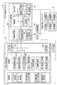
- FIG. 2 is a diagram showing a configuration example of the topology estimation system 1 according to the present embodiment.
- the topology estimation system 1 mainly includes a topology estimation device 10, a traffic addition device 50, and a traffic collection device 90.
- the topology estimation apparatus 10 determines how the plurality of network devices A to F included in the predetermined estimation target network N are connected, that is, the plurality of interfaces in the plurality of network devices A to F. The connection relationship (topology) of the.
- the topology estimation device 10 shown in FIG. 2 is the same as the topology estimation device 10 shown in FIG. However, in the present embodiment, the traffic addition determination unit 11 is added between the connection form generation unit (23) and the traffic amount calculation unit (24).
- the reference numerals in parentheses shown in FIG. 2 are the same as those in Patent Document 2.
- FIG. 2 among the connection lines between the functional units shown in FIG. 1 of Patent Document 2, only those that are main in processing are shown by broken lines, and the other connection lines are omitted.
- the present embodiment is characterized by a functional unit having a dot hatch and a connecting line shown by a solid line.
- a traffic addition device 50 is added to the system configuration of Patent Document 2. Therefore, first, a configuration example of the traffic addition device 50 will be described.
- the traffic addition device 50 mainly includes a setting input unit 51, a traffic generation unit 52, a traffic transmission unit 53, a traffic information storage unit 54, and a transmission destination interface storage unit 55. It is equipped with.
- the setting input unit 51 reads out the traffic information from the traffic information storage unit 54, and based on the amount of traffic of the estimation target network N included in the traffic information, the setting input unit 51 selects a plurality of network devices A to F included in the estimation target network N. It is equipped with a function to calculate the amount of traffic additionally sent to each interface.
- the setting input unit 51 has a function of calculating the amount of traffic added to each traffic based on the amount of each traffic flowing in each of the plurality of interfaces in the plurality of network devices A to F. Prepare At this time, the setting input unit 51 calculates such that the amount of traffic added to each traffic is different for each interface.
- the traffic generation unit 52 has a function of generating a different amount of traffic at each interface calculated by the setting input unit 51.
- the traffic means data (information) flowing through the network, and in the present embodiment, since the network device is targeted, the traffic generation unit 52 generates packets of different data sizes at the respective interfaces. It is also possible to include a server device in addition to the network device, and the data size of the segment may be changed instead of the packet.
- the traffic transmission unit 53 has a function of transmitting packets of different data sizes generated by the traffic generation unit 52 to the plurality of network devices A to F and outputting the packets from the respective interfaces of the plurality of network devices A to F. Equipped with.
- the traffic transmission unit 53 adds different amounts of traffic at the interfaces generated by the traffic generation unit 52 to the traffic output from the interfaces of the network devices A to F, respectively.
- the traffic information storage unit 54 has a function to readably store the traffic information of the estimation target network N. Specifically, the traffic information storage unit 54 readablely stores, as traffic information, each traffic flowing in each of the plurality of interfaces in the plurality of network devices A to F and the amount thereof.
- the destination interface storage unit 55 has a function of storing the interface ID of the destination to which the traffic is added by transmitting the packet by the traffic transmitter 53 in association with the network device ID so as to be readable as destination information.
- the setting input unit 51, the traffic generation unit 52, and the traffic transmission unit 53 respectively correspond to the “traffic amount calculation unit” and the “traffic addition unit” described in the claims.
- the topology estimation device 10 is a device that estimates the connection relationship (topology) of the interfaces from the correlation of the traffic amounts of the plurality of interfaces in the plurality of network devices.
- the topology estimation device 10 is configured by further including a traffic addition determination unit 11 in the configuration described in Patent Document 2.
- the traffic addition determination unit 11 functions between the connection form generation unit (23) and the traffic amount calculation unit (24), and determines the traffic amount of the estimation target network N before estimating and calculating the topology of the estimation target network N. Based on the change, a function of determining whether to add traffic to the traffic of the estimation target network N is provided.
- the traffic addition determination unit 11 determines whether or not to add traffic to each traffic based on the change in the amount of each traffic flowing through each of the plurality of interfaces in the plurality of network devices AF.
- the configuration example of the topology estimation device 10 has been described.
- the case where the topology estimation device 10 includes the traffic addition determination unit 11 will be described as an example, but the traffic addition device 50 may include the traffic addition determination unit 11.
- the traffic addition device 50 may include the traffic addition determination unit 11.
- the traffic collection device 90 has a function of collecting traffic information from the estimation target network N. Specifically, the traffic collection device 90 collects each traffic flowing in each of the plurality of interfaces in the plurality of network devices A to F, and the amount thereof, and together with the acquisition time (time stamp) of each traffic information, the topology estimation. It is transmitted to the input unit (31) of the device 10.
- Example of traffic addition method/variable traffic amount addition method Next, an embodiment of a method of adding traffic and a method of changing the traffic amount to be added will be described.
- the traffic addition process and the traffic amount variable process are performed by the traffic generation unit 52 and the traffic transmission unit 53 of the traffic addition device 50.
- the traffic adding device 50 remotely logs in to the network device E using Telnet or the like, There is a method in which traffic is added to the network devices A, C, D, and F by sending packets using ping or the like.
- the amount of traffic to be added for example, there is a method of changing the amount of traffic to be added by changing the data size per packet.
- the data size of a packet can be specified arbitrarily, and different data sizes are specified for each interface calculated by the setting input unit 51.
- FIG. 3 when adding traffic to the traffic output from the network device E to the network device A, "ping-l100-ip.addr_A_sby" is executed. “100” is the data size of the packet.
- the traffic may be added by the user using the management system (OpS: Operation System), or the traffic adding device 50 may execute the script of the ping command.
- OpS Operation System
- the setting process of the traffic addition device 50 is performed by the setting input unit 51 of the traffic addition device 50.
- the average amount of traffic flowing through each interface of the protection system does not always have the same value as shown in FIG. Therefore, it is necessary to change the amount of traffic to be added based on the amount that constantly flows.
- base values include average value, maximum value, minimum value, median value, and the like.
- the average value of the traffic amount that constantly flows in the operation system device is viewed, and the calculation is performed so as to add the traffic having an arbitrary X [%] to the average traffic amount.
- new_IF_Y i (t) which is the amount of traffic flowing to each IF when traffic is added, can be calculated using equation (1).
- add_IF_Y i indicates the amount of traffic to be added.
- the traffic addition determination unit 11 determines whether or not to add traffic based on the change in the traffic volume of the network input to the topology estimation device 10.
- the non-operation system automatically switches to the operation system when an error occurs, so there is no need to send additional traffic when it becomes the operation system.
- the necessity of packet addition is determined by observing the traffic amount waveform (change amount). Specifically, when the standard deviation of the traffic volume within a predetermined time is smaller than the threshold value, the calculated traffic volume to be added is additionally passed, and when the standard deviation is larger than the threshold value, the traffic is not added.
- FIG. 6 is a diagram showing a processing flow of the traffic addition method.
- Step S1 First, the traffic collection device 90 collects and collects the amount of each traffic flowing from each of the plurality of network devices AF included in the estimation target network N to each of the plurality of interfaces of the plurality of network devices AF.
- the traffic information is transmitted to the input unit (31) of the topology estimation apparatus 10 together with the time stamp.
- Step S2 upon receiving the traffic information from the traffic collection device 90, the topology estimation device 10 causes the traffic addition determination unit 11 to temporally determine the amount of each traffic flowing through the plurality of interfaces in the plurality of network devices AF. Based on the change, whether to add traffic to each traffic is determined. For example, when the standard deviation of each traffic amount is less than the threshold value, it is determined that the traffic is added, and when the standard deviation of each traffic amount is the threshold value or more, it is determined that the traffic is not added. At this time, the topology estimation apparatus 10 may determine whether to add traffic based on the slope of the change in the waveform of the traffic volume. When it is determined that no traffic is added, steps S3 to S9 are skipped and the process proceeds to step S10.
- Step S3 If it is determined that the traffic is added, the traffic addition determination unit 11 transmits the traffic information received from the traffic collection device 90 to the traffic addition device 50, and the traffic addition device 50 stores the traffic information in the traffic information storage unit 54. Save to.
- Step S4 the setting input unit 51 of the traffic addition device 50 reads out and refers to the traffic information from the traffic information storage unit 54, and also determines the amount of each traffic flowing through the plurality of interfaces in the plurality of network devices AF. In addition, the amount of traffic to be added to each traffic is calculated so that the amount of traffic differs for each interface.
- Step S5 Next, the traffic generation unit 52 generates different amounts of traffic at each interface calculated in step S4. For example, the traffic generation unit 52 generates a packet having a different data size at each interface.
- Step S6 Next, the traffic transmission unit 53 transmits the packets of different data sizes generated in step S5 to the plurality of network devices A to F in the estimation target network N, and the interfaces of the plurality of network devices A to F are transmitted. To output respectively.
- Step S7 the traffic transmission unit 53 associates the network device ID of the transmission destination, which has transmitted the packet in step S6, with each interface ID and stores it in the transmission destination interface storage unit 55 as transmission destination information.
- Step S10 After that, in the topology estimation apparatus 10, when the traffic information is re-received from the traffic collection apparatus 90, the traffic amount calculation unit (24) or the like estimates and calculates the topology of the estimation target network N using the re-received traffic information.
- the traffic adding device 50 adds different amounts of traffic to the respective traffics output from the plurality of interfaces in the plurality of network devices AF in the estimation target network N, respectively. Since the feature amount is formed in the traffic, the topology estimation device 10 can correctly grasp the connection relation of the interface from the correlation of the traffic amount.
- the topology estimation device 10, the traffic addition device 50, and the traffic collection device 90 described in this embodiment can be realized by a computer including a CPU, a memory, an input/output interface, a communication interface, and the like. It is also possible to create a program for causing a computer to function as these devices, and a storage medium for the program.
Landscapes
- Engineering & Computer Science (AREA)
- Computer Networks & Wireless Communication (AREA)
- Signal Processing (AREA)
- Environmental & Geological Engineering (AREA)
- Data Exchanges In Wide-Area Networks (AREA)
Abstract
インタフェースの接続関係を正確に把握可能にする。トラフィック付加装置50が、推定対象ネットワークNにおいて複数のネットワーク装置A~Fで複数のインタフェースからそれぞれ出力される各トラフィックに、各インタフェースで異なる量のトラフィックをそれぞれ付加する。これにより、トラフィックに特徴量が形成されることから、トポロジ推定装置10は、トラフィック量の相関性からインタフェースの接続関係を正しく把握可能となる。
Description
本発明は、トラフィックを付加する技術に関する。
従来、トポロジを把握する手段が検討されている。トポロジとは、複数のネットワーク装置等がどのように接続されているかを示すレイアウトであり、特許文献1,2では、複数のインタフェースにおけるトラフィック量の相関性からインタフェースの接続関係を推定する方法が提案されている。
例えば、図7に示すように、所定の推定対象ネットワークにおいて、複数のネットワーク装置A,B,・・・がそれぞれ備える各インタフェースA1,A2,・・・,B1,B2,・・・におけるトラフィック送受信量をそれぞれ算出し、同一時刻tでトラフィック送受信量の等しいインタフェース同士が接続されていると推定する。
このようなトラフィック情報は、例えば、ルータ、スイッチ等、ネットワーク装置等で一般的に取得可能な性能情報であるため、装置の製造元等に関係なくトポロジ情報の取得に利用可能である。
しかしながら、上記従来手法を用いてトラフィックに変動がない状況でトポロジを推定する場合、各インタフェースでトラフィック量に差分が生じないため、正しい接続関係の推定が困難となる課題がある。
例えば、通信キャリアの商用網には、障害発生時の予備系である非運用系のネットワーク装置が存在する。非運用系は、同一ネットワーク装置の各インタフェースでトラフィック量がほぼ一定で特徴的な変化がないため、従来手法ではトポロジの推定が困難である。
具体的には、図8(a)に示すように、複数のインタフェースA1~A10におけるトラフィック送受信量に差がなく、複数のインタフェースB1~B10におけるトラフィック送受信量にも差がないため、所定のインタフェースAに対してトラフィック量の等しいインタフェースBが複数存在することから、図8(b)に示すような誤った接続関係を推定してしまう。
本発明は、上記事情を鑑みてなされたものであり、インタフェースの接続関係を正確に把握可能にすることを目的とする。
本発明のトポロジ推定システムは、複数のネットワーク装置における複数のインタフェースでのトラフィック量の相関性からインタフェースの接続関係を求めるトポロジ推定装置と、トラフィック付加装置と、を備えたトポロジ推定システムにおいて、前記トラフィック付加装置は、前記複数のインタフェースからそれぞれ出力される各トラフィックに、各インタフェースで異なる量のトラフィックをそれぞれ付加するトラフィック付加部を備えることを特徴とする。
上記トポロジ推定システムにおいて、前記トラフィック付加装置は、前記複数のインタフェースにそれぞれ流れる各トラフィックの量をもとに、前記各トラフィックにそれぞれ付加するトラフィックの量を算出するトラフィック量算出部を更に備えることを特徴とする。
上記トポロジ推定システムにおいて、前記トポロジ推定装置は、前記複数のインタフェースにそれぞれ流れる各トラフィックの量の変化に基づき、前記各トラフィックにトラフィックを付加するか否かを判定するトラフィック付加判定部を備えることを特徴とする。
本発明のトラフィック付加装置は、複数のインタフェースからそれぞれ出力される各トラフィックに、各インタフェースで異なる量のトラフィックをそれぞれ付加するトラフィック付加部を備えることを特徴とする。
上記トラフィック付加装置において、前記複数のインタフェースにそれぞれ流れる各トラフィックの量をもとに、前記各トラフィックにそれぞれ付加するトラフィックの量を算出するトラフィック量算出部を更に備えることを特徴とする。
上記トラフィック付加装置において、前記複数のインタフェースにそれぞれ流れる各トラフィックの量の変化に基づき、前記各トラフィックにトラフィックを付加するか否かを判定するトラフィック付加判定部を更に備えることを特徴とする。
本発明のトラフィック付加方法は、複数のネットワーク装置における複数のインタフェースでのトラフィック量の相関性からインタフェースの接続関係を求めるトポロジ推定装置と、トラフィック付加装置と、で行うトラフィック付加方法において、前記トポロジ推定装置は、前記複数のインタフェースにそれぞれ流れる各トラフィックの量の変化に基づき、前記各トラフィックにトラフィックを付加するか否かを判定し、前記トラフィック付加装置は、トラフィックを付加する場合、前記複数のインタフェースにそれぞれ流れる各トラフィックの量をもとに、前記各トラフィックにそれぞれ付加するトラフィックの量を算出し、前記複数のインタフェースからそれぞれ出力される各トラフィックに、算出した各インタフェースで異なる量のトラフィックをそれぞれ付加することを特徴とする。
本発明によれば、インタフェースの接続関係を正確に把握可能にすることができる。
<発明の概要>
従来手法では、トラフィック量が一定であったり、トラフィック量に特徴的な変化がない状況(例えば、トラフィック量の傾向が似ているネットワーク装置が複数存在する状況等)において、正しい対向装置の識別が困難となる。
従来手法では、トラフィック量が一定であったり、トラフィック量に特徴的な変化がない状況(例えば、トラフィック量の傾向が似ているネットワーク装置が複数存在する状況等)において、正しい対向装置の識別が困難となる。
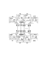
そこで、本発明では、図1に示すように、隣接するネットワーク装置等の各インタフェースにそれぞれ異なる量のパケットPA1,PA2,・・・,PB1,PB2,・・・を付加するようにする。これにより、トラフィックに特徴量が形成されるので、トラフィック量の相関性からインタフェースの接続関係を正しく把握可能となる。
以下、本発明を実施する一実施形態について図面を用いて説明する。
<システム構成例>
図2は、本実施形態に係るトポロジ推定システム1の構成例を示す図である。トポロジ推定システム1は、図2に示すように、主として、トポロジ推定装置10と、トラフィック付加装置50と、トラフィック収集装置90と、を備えて構成される。トポロジ推定システム1では、トポロジ推定装置10が、所定の推定対象ネットワークNに含まれる複数のネットワーク装置A~Fがどのように接続されているか、つまり、複数のネットワーク装置A~Fにおける複数のインタフェースの接続関係(トポロジ)を推定する。
図2は、本実施形態に係るトポロジ推定システム1の構成例を示す図である。トポロジ推定システム1は、図2に示すように、主として、トポロジ推定装置10と、トラフィック付加装置50と、トラフィック収集装置90と、を備えて構成される。トポロジ推定システム1では、トポロジ推定装置10が、所定の推定対象ネットワークNに含まれる複数のネットワーク装置A~Fがどのように接続されているか、つまり、複数のネットワーク装置A~Fにおける複数のインタフェースの接続関係(トポロジ)を推定する。
図2に示したトポロジ推定装置10は、特許文献2の図1に示されたトポロジ推定装置10と同様である。但し、本実施形態では、接続形態生成部(23)とトラフィック量計算部(24)との間にトラフィック付加判定部11を追加した。図2に示した()付きの符号は、特許文献2の符号を流用している。また、図2では、特許文献2の図1に示された機能部間の接続線のうち処理上主要なもののみを破線で示し、それ以外の接続線は省略した。図2において、本実施形態では、点ハッチが入れられた機能部、実線で示された接続線が特徴である。
<トラフィック付加装置の構成例>
図2に示したシステム構成において、本実施形態では、特許文献2のシステム構成に対し、トラフィック付加装置50を追加した。そこでまず、トラフィック付加装置50の構成例について説明する。
図2に示したシステム構成において、本実施形態では、特許文献2のシステム構成に対し、トラフィック付加装置50を追加した。そこでまず、トラフィック付加装置50の構成例について説明する。
トラフィック付加装置50は、図2に示したように、主として、設定入力部51と、トラフィック生成部52と、トラフィック送信部53と、トラフィック情報保存部54と、送信先インタフェース保存部55と、を備えて構成される。
設定入力部51は、トラフィック情報保存部54からトラフィック情報を読み出して、トラフィック情報に含まれる推定対象ネットワークNのトラフック量をもとに、推定対象ネットワークNに含まれる複数のネットワーク装置A~Fの各インタフェースにそれぞれ追加で流すトラフィックの量を算出する機能を備える。
具体的には、設定入力部51は、複数のネットワーク装置A~Fにおける複数のインタフェースにそれぞれ流れている各トラフィックの量をもとに、各トラフィックにそれぞれ付加するトラフィックの量を算出する機能を備える。このとき、設定入力部51は、各トラフィックにそれぞれ付加するトラフィックの量が各インタフェースで異なるように算出する。
トラフィック生成部52は、設定入力部51で算出された各インタフェースで異なる量のトラフィックをそれぞれ生成する機能を備える。ここで、トラフィックとはネットワークを流れるデータ(情報)をいい、本実施形態ではネットワーク装置を対象とするため、トラフィック生成部52は、各インタフェースで異なるデータサイズのパケットをそれぞれ生成する。尚、ネットワーク装置以外にサーバ装置を対象に含めることも可能であり、パケットに代えてセグメントのデータサイズを変更してもよい。
トラフィック送信部53は、トラフィック生成部52で生成された各インタフェースで異なるデータサイズのパケットを複数のネットワーク装置A~Fにそれぞれ送信し、複数のネットワーク装置A~Fにおける各インタフェースからそれぞれ出力させる機能を備える。
すなわち、トラフィック送信部53は、複数のネットワーク装置A~Fにおける複数のインタフェースからそれぞれ出力されている各トラフィックに、トラフィック生成部52で生成された各インタフェースで異なる量のトラフィックをそれぞれ付加する。
トラフィック情報保存部54は、推定対象ネットワークNのトラフィック情報を読み出し可能に記憶しておく機能を備える。具体的には、トラフィック情報保存部54は、複数のネットワーク装置A~Fにおける複数のインタフェースにそれぞれ流れている各トラフィック及びその量をトラフィック情報として読み出し可能に記憶する。
送信先インタフェース保存部55は、トラフィック送信部53がパケットを送信することでトラフィックを付加した送信先のインタフェースIDをネットワーク装置IDに関連付けて送信先情報として読み出し可能に記憶しておく機能を備える。
ここまで、トラフィック付加装置50の構成例について説明した。尚、設定入力部51とトラフィック生成部52及びトラフィック送信部53とは、それぞれ、特許請求の範囲に記載した「トラフィック量算出部」と「トラフィック付加部」とに対応する。
<トポロジ推定装置の構成例>
次に、トポロジ推定装置10の構成例について説明する。トポロジ推定装置10は、特許文献2に記載の通り、複数のネットワーク装置における複数のインタフェースでのトラフィック量の相関性からインタフェースの接続関係(トポロジ)を推定する装置である。本実施形態において、トポロジ推定装置10は、特許文献2に記載の構成に、トラフィック付加判定部11を更に備えて構成される。
次に、トポロジ推定装置10の構成例について説明する。トポロジ推定装置10は、特許文献2に記載の通り、複数のネットワーク装置における複数のインタフェースでのトラフィック量の相関性からインタフェースの接続関係(トポロジ)を推定する装置である。本実施形態において、トポロジ推定装置10は、特許文献2に記載の構成に、トラフィック付加判定部11を更に備えて構成される。
トラフィック付加判定部11は、接続形態生成部(23)とトラフィック量計算部(24)との間で機能し、推定対象ネットワークNのトポロジを推定計算する前に、推定対象ネットワークNのトラフック量の変化に基づき、推定対象ネットワークNのトラフィックに対してトラフィックを付加するか否かを判定する機能を備える。
具体的には、トラフィック付加判定部11は、複数のネットワーク装置A~Fにおける複数のインタフェースにそれぞれ流れる各トラフィックの量の変化に基づき、各トラフィックにトラフィックを付加するか否かを判定する。
ここまで、トポロジ推定装置10の構成例について説明した。尚、本実施形態では、トポロジ推定装置10がトラフィック付加判定部11を備える場合を例に説明するが、トラフィック付加装置50がトラフィック付加判定部11を備えてもよい。その他、トラフィック付加判定部11以外の各機能部については、特許文献2の説明を参照されたい。
<トラフィック収集装置>
次に、トラフィック収集装置90について説明する。トラフィック収集装置90は、推定対象ネットワークNからトラフィック情報を収集する機能を備える。具体的には、トラフィック収集装置90は、複数のネットワーク装置A~Fにおける複数のインタフェースにそれぞれ流れている各トラフィック及びその量を収集し、各トラフィック情報の取得時刻(タイムスタンプ)とともに、トポロジ推定装置10の入力部(31)に送信する。
次に、トラフィック収集装置90について説明する。トラフィック収集装置90は、推定対象ネットワークNからトラフィック情報を収集する機能を備える。具体的には、トラフィック収集装置90は、複数のネットワーク装置A~Fにおける複数のインタフェースにそれぞれ流れている各トラフィック及びその量を収集し、各トラフィック情報の取得時刻(タイムスタンプ)とともに、トポロジ推定装置10の入力部(31)に送信する。
<トラフィックの付加方法/付加するトラフィック量の可変方法の実施例>
続いて、トラフィックの付加方法及び付加するトラフィック量の可変方法の実施例について説明する。トラフィック付加処理及びトラフィック量の可変処理は、トラフィック付加装置50のトラフィック生成部52及びトラフィック送信部53で行われる。
続いて、トラフィックの付加方法及び付加するトラフィック量の可変方法の実施例について説明する。トラフィック付加処理及びトラフィック量の可変処理は、トラフィック付加装置50のトラフィック生成部52及びトラフィック送信部53で行われる。
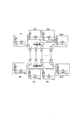
隣接する複数のネットワーク装置A~Fに対してトラフィックを付加する方法としては、例えば、図3に示すように、トラフィック付加装置50が、Telnet等を用いてネットワーク装置Eに遠隔ログインし、隣接するネットワーク装置A,C,D,Fにping等を用いてパケットを流すことで、トラフィックを付加する方法がある。
付加するトラフィックの量を可変する方法としては、例えば、1パケットあたりのデータサイズを可変させることで、付加するトラフィック量を変化させる方法がある。pingではパケットのデータサイズを任意に指定可能であり、設定入力部51で算出された各インタフェースで異なるデータサイズを指定する。図3において、ネットワーク装置Eからネットワーク装置Aへ出力されるトラフィックにトラフィックを付加する場合、「ping -l 100 ip.addr_A_sby」を実行する。「100」がパケットのデータサイズである。同様に、ネットワーク装置Eから、ネットワーク装置C,D,Eへそれぞれ出力されるトラフィックにトラフィックを付加する場合、「ping -l 200 ip.addr_C_sby」、「ping -l 300 ip.addr_D_sby」、「ping -l 400 ip.addr_E_sby」をそれぞれ実行する。
これにより、ネットワーク装置Eの各インタフェースからそれぞれ出力されるトラフィックに特徴が与えられる。尚、トラフィックの付加は、管理システム(OpS:Operation System)を用いてユーザが実施してもよいし、トラフィック付加装置50が上記pingコマンドのスクリプトを実行してもよい。
<付加するトラフィック量の算出方法の実施例>
次に、付加するトラフィック量の算出方法の実施例について説明する。付加するトラフィック量の算出処理は、トラフィック付加装置50の設定入力部51で行われる。
次に、付加するトラフィック量の算出方法の実施例について説明する。付加するトラフィック量の算出処理は、トラフィック付加装置50の設定入力部51で行われる。
ここで、非運用系装置の各インタフェースに流れる平均トラフィック量は、図4に示したように、同じ値になるとは限らない。そこで、定常的に流れている量をベースに、付加するトラフィック量を可変する必要がある。ベースとする値としては、平均値、最大値、最小値、中央値等があげられる。
例えば、運用系装置に定常的に流れているトラフィック量の平均値をみて、平均トラフィック量に対する任意のX[%]であるトラフィックを付加するように計算する。具体的には、ネットワーク装置Yの各IF(IF_Y1,IF_Y2,・・・)について、元の流れているトラフィック量をIF_Yi(t)(i=1,2,・・・)とする。このとき、トラフィックを付加した際に各IFに流れるトラフィック量であるnew_IF_Yi(t)は、式(1)を用いて算出できる。尚、add_IF_Yiは、追加するトラフィックの量を示す。

<トラフィックを追加する判定方法の実施例>
次に、トラフィックを追加する判定方法の実施例について説明する。トラフィックを追加する判定処理は、トポロジ推定装置10のトラフィック付加判定部11で行われる。
次に、トラフィックを追加する判定方法の実施例について説明する。トラフィックを追加する判定処理は、トポロジ推定装置10のトラフィック付加判定部11で行われる。
トラフィック付加判定部11は、トポロジ推定装置10に入力されたネットワークのトラフィック量の変化から、トラフィックを付加するか否かを判定する。非運用系は、運用系に異常発生時に自動的に切り替わるため、運用系になった時にはトラフィックを追加で流す必要がない。切り替わった際は、別の装置になった非運用系にトラフィックを付加する必要がある。そこで、図5に示すように、例えば、トラフィック量の波形(変化量)をみて、パケット付加の必要性を判定する。具体的には、所定時間内におけるトラフィック量の標準偏差が閾値よりも小さい場合、算出した付加するべきトラフィック量を追加で流し、その標準偏差が閾値よりも大きい場合、トラフィックは追加しない。また、標準偏差に加えて又は単独で、トラフィック量の波形の変化の傾きに基づき、その傾きが正の場合にはトラフィックを追加し、その傾きが負の場合にはトラフィックを追加しないようにしてもよい。
<トポロジ推定システムの動作例>
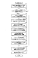
続いて、トポロジ推定システム1で行うトラフィック付加方法について説明する。図6は、トラフィック付加方法の処理フローを示す図である。
続いて、トポロジ推定システム1で行うトラフィック付加方法について説明する。図6は、トラフィック付加方法の処理フローを示す図である。
ステップS1;
まず、トラフィック収集装置90が、推定対象ネットワークNに含まれる複数のネットワーク装置A~Fから、複数のネットワーク装置A~Fにおける複数のインタフェースにそれぞれ流れている各トラフィックの量を収集し、収集したトラフィック情報をそのタイムスタンプとともにトポロジ推定装置10の入力部(31)へ送信する。
まず、トラフィック収集装置90が、推定対象ネットワークNに含まれる複数のネットワーク装置A~Fから、複数のネットワーク装置A~Fにおける複数のインタフェースにそれぞれ流れている各トラフィックの量を収集し、収集したトラフィック情報をそのタイムスタンプとともにトポロジ推定装置10の入力部(31)へ送信する。
ステップS2;
次に、トポロジ推定装置10は、トラフィック収集装置90からトラフィック情報を受信すると、トラフィック付加判定部11が、複数のネットワーク装置A~Fにおける複数のインタフェースにそれぞれ流れている各トラフィックの量の時間的変化に基づき、各トラフィックにトラフィックを付加するか否かを判定する。例えば、各トラフィック量の標準偏差が閾値未満の場合、トラフィックを付加すると判定し、各トラフィック量の標準偏差が閾値以上の場合、トラフィックを付加しないと判定する。このとき、トポロジ推定装置10は、トラフィック量の波形の変化の傾きに基づきトラフィックを付加するか否かを判定してもよい。トラフィックを付加しないと判定した場合、ステップS3~S9をスキップしてステップS10へ進む。
次に、トポロジ推定装置10は、トラフィック収集装置90からトラフィック情報を受信すると、トラフィック付加判定部11が、複数のネットワーク装置A~Fにおける複数のインタフェースにそれぞれ流れている各トラフィックの量の時間的変化に基づき、各トラフィックにトラフィックを付加するか否かを判定する。例えば、各トラフィック量の標準偏差が閾値未満の場合、トラフィックを付加すると判定し、各トラフィック量の標準偏差が閾値以上の場合、トラフィックを付加しないと判定する。このとき、トポロジ推定装置10は、トラフィック量の波形の変化の傾きに基づきトラフィックを付加するか否かを判定してもよい。トラフィックを付加しないと判定した場合、ステップS3~S9をスキップしてステップS10へ進む。
ステップS3;
トラフィックを付加すると判定した場合、トラフィック付加判定部11は、トラフィック収集装置90から受信していたトラフィック情報をトラフィック付加装置50へ送信し、トラフィック付加装置50は、そのトラフィック情報をトラフィック情報保存部54に保存する。
トラフィックを付加すると判定した場合、トラフィック付加判定部11は、トラフィック収集装置90から受信していたトラフィック情報をトラフィック付加装置50へ送信し、トラフィック付加装置50は、そのトラフィック情報をトラフィック情報保存部54に保存する。
ステップS4;
次に、トラフィック付加装置50の設定入力部51は、トラフィック情報保存部54からトラフィック情報を読み出して参照し、複数のネットワーク装置A~Fにおける複数のインタフェースにそれぞれ流れている各トラフィックの量をもとに、各インタフェースで異なるトラフィック量となるように、各トラフィックにそれぞれ付加するトラフィックの量を算出する。
次に、トラフィック付加装置50の設定入力部51は、トラフィック情報保存部54からトラフィック情報を読み出して参照し、複数のネットワーク装置A~Fにおける複数のインタフェースにそれぞれ流れている各トラフィックの量をもとに、各インタフェースで異なるトラフィック量となるように、各トラフィックにそれぞれ付加するトラフィックの量を算出する。
ステップS5;
次に、トラフィック生成部52は、ステップS4で算出された各インタフェースで異なる量のトラフィックをそれぞれ生成する。例えば、トラフィック生成部52は、各インタフェースで異なるデータサイズのパケットを生成する。
次に、トラフィック生成部52は、ステップS4で算出された各インタフェースで異なる量のトラフィックをそれぞれ生成する。例えば、トラフィック生成部52は、各インタフェースで異なるデータサイズのパケットを生成する。
ステップS6;
次に、トラフィック送信部53は、ステップS5で生成された各インタフェースで異なるデータサイズのパケットを推定対象ネットワークNにおける複数のネットワーク装置A~Fへ送信し、複数のネットワーク装置A~Fの各インタフェースからそれぞれ出力させる。
次に、トラフィック送信部53は、ステップS5で生成された各インタフェースで異なるデータサイズのパケットを推定対象ネットワークNにおける複数のネットワーク装置A~Fへ送信し、複数のネットワーク装置A~Fの各インタフェースからそれぞれ出力させる。
ステップS7;
次に、トラフィック送信部53は、ステップS6でパケットを送信した送信先のネットワーク装置IDと各インタフェースIDとを関連付けて送信先情報として送信先インタフェース保存部55に格納する。
次に、トラフィック送信部53は、ステップS6でパケットを送信した送信先のネットワーク装置IDと各インタフェースIDとを関連付けて送信先情報として送信先インタフェース保存部55に格納する。
ステップS8;
次に、トラフィック収集装置90は、推定対象ネットワークNに含まれる複数のネットワーク装置A~Fから、複数のネットワーク装置A~Fにおける複数のインタフェースにそれぞれ流れている各トラフィックの量を再収集する。
次に、トラフィック収集装置90は、推定対象ネットワークNに含まれる複数のネットワーク装置A~Fから、複数のネットワーク装置A~Fにおける複数のインタフェースにそれぞれ流れている各トラフィックの量を再収集する。
ステップS9;
次に、トラフィック収集装置90は、ステップS8で再収集したトラフィック情報をトポロジ推定装置10の入力部(31)へ送信する。
次に、トラフィック収集装置90は、ステップS8で再収集したトラフィック情報をトポロジ推定装置10の入力部(31)へ送信する。
ステップS10;
その後、トポロジ推定装置10は、トラフィック収集装置90からトラフィック情報を再受信すると、トラフィック量計算部(24)等が、再受信したトラフィック情報を用いて推定対象ネットワークNのトポロジを推定計算する。
その後、トポロジ推定装置10は、トラフィック収集装置90からトラフィック情報を再受信すると、トラフィック量計算部(24)等が、再受信したトラフィック情報を用いて推定対象ネットワークNのトポロジを推定計算する。
ステップS11;
最後に、トポロジ推定装置10の出力部(32)は、ステップS10で推定計算した推定対象ネットワークNのトポロジをモニタに表示し、ファイルに保存する。
最後に、トポロジ推定装置10の出力部(32)は、ステップS10で推定計算した推定対象ネットワークNのトポロジをモニタに表示し、ファイルに保存する。
<実施形態の効果>
最後に、本実施形態の効果について説明する。本実施形態によれば、トラフィック付加装置50が、推定対象ネットワークNにおける複数のネットワーク装置A~Fで複数のインタフェースからそれぞれ出力される各トラフィックに、各インタフェースで異なる量のトラフィックをそれぞれ付加するので、トラフィックに特徴量が形成されることから、トポロジ推定装置10は、トラフィック量の相関性からインタフェースの接続関係を正しく把握可能となる。
最後に、本実施形態の効果について説明する。本実施形態によれば、トラフィック付加装置50が、推定対象ネットワークNにおける複数のネットワーク装置A~Fで複数のインタフェースからそれぞれ出力される各トラフィックに、各インタフェースで異なる量のトラフィックをそれぞれ付加するので、トラフィックに特徴量が形成されることから、トポロジ推定装置10は、トラフィック量の相関性からインタフェースの接続関係を正しく把握可能となる。
尚、本実施形態で説明したトポロジ推定装置10、トラフィック付加装置50、トラフィック収集装置90は、CPU、メモリ、入出力インタフェース、通信インタフェース等を備えたコンピュータで実現可能である。また、それらの装置としてコンピュータを機能させるためのプログラム、そのプログラムの記憶媒体の作成も可能である。
1…トポロジ推定システム
10…トポロジ推定装置
11…トラフィック付加判定部
50…トラフィック付加装置
51…設定入力部
52…トラフィック生成部
53…トラフィック送信部
54…トラフィック情報保存部
55…送信先インタフェース保存部
90…トラフィック収集装置
10…トポロジ推定装置
11…トラフィック付加判定部
50…トラフィック付加装置
51…設定入力部
52…トラフィック生成部
53…トラフィック送信部
54…トラフィック情報保存部
55…送信先インタフェース保存部
90…トラフィック収集装置
Claims (7)
- 複数の装置における複数のインタフェースでのトラフィック量の相関性からインタフェースの接続関係を求めるトポロジ推定装置と、トラフィック付加装置と、を備えたトポロジ推定システムにおいて、
前記トラフィック付加装置は、
前記複数のインタフェースからそれぞれ出力される各トラフィックに、各インタフェースで異なる量のトラフィックをそれぞれ付加するトラフィック付加部を備えることを特徴とするトポロジ推定システム。 - 前記トラフィック付加装置は、
前記複数のインタフェースにそれぞれ流れる各トラフィックの量をもとに、前記各トラフィックにそれぞれ付加するトラフィックの量を算出するトラフィック量算出部を更に備えることを特徴とする請求項1に記載のトポロジ推定システム。 - 前記トポロジ推定装置は、
前記複数のインタフェースにそれぞれ流れる各トラフィックの量の変化に基づき、前記各トラフィックにトラフィックを付加するか否かを判定するトラフィック付加判定部を備えることを特徴とする請求項1又は2に記載のトポロジ推定システム。 - 複数のインタフェースからそれぞれ出力される各トラフィックに、各インタフェースで異なる量のトラフィックをそれぞれ付加するトラフィック付加部を備えることを特徴とするトラフィック付加装置。
- 前記複数のインタフェースにそれぞれ流れる各トラフィックの量をもとに、前記各トラフィックにそれぞれ付加するトラフィックの量を算出するトラフィック量算出部を更に備えることを特徴とする請求項4に記載のトラフィック付加装置。
- 前記複数のインタフェースにそれぞれ流れる各トラフィックの量の変化に基づき、前記各トラフィックにトラフィックを付加するか否かを判定するトラフィック付加判定部を更に備えることを特徴とする請求項4又は5に記載のトラフィック付加装置。
- 複数の装置における複数のインタフェースでのトラフィック量の相関性からインタフェースの接続関係を求めるトポロジ推定装置と、トラフィック付加装置と、で行うトラフィック付加方法において、
前記トポロジ推定装置は、
前記複数のインタフェースにそれぞれ流れる各トラフィックの量の変化に基づき、前記各トラフィックにトラフィックを付加するか否かを判定し、
前記トラフィック付加装置は、
トラフィックを付加する場合、前記複数のインタフェースにそれぞれ流れる各トラフィックの量をもとに、前記各トラフィックにそれぞれ付加するトラフィックの量を算出し、 前記複数のインタフェースからそれぞれ出力される各トラフィックに、算出した各インタフェースで異なる量のトラフィックをそれぞれ付加する
ことを特徴とするトラフィック付加方法。
Priority Applications (1)
| Application Number | Priority Date | Filing Date | Title |
|---|---|---|---|
| US17/427,827 US12237976B2 (en) | 2019-02-06 | 2020-01-23 | Topology deduction system, traffic addition device, and traffic addition method |
Applications Claiming Priority (2)
| Application Number | Priority Date | Filing Date | Title |
|---|---|---|---|
| JP2019019341A JP7111974B2 (ja) | 2019-02-06 | 2019-02-06 | トポロジ推定システム、トラフィック付加装置及びトラフィック付加方法 |
| JP2019-019341 | 2019-02-06 |
Publications (1)
| Publication Number | Publication Date |
|---|---|
| WO2020162197A1 true WO2020162197A1 (ja) | 2020-08-13 |
Family
ID=71947611
Family Applications (1)
| Application Number | Title | Priority Date | Filing Date |
|---|---|---|---|
| PCT/JP2020/002250 Ceased WO2020162197A1 (ja) | 2019-02-06 | 2020-01-23 | トポロジ推定システム、トラフィック付加装置及びトラフィック付加方法 |
Country Status (3)
| Country | Link |
|---|---|
| US (1) | US12237976B2 (ja) |
| JP (1) | JP7111974B2 (ja) |
| WO (1) | WO2020162197A1 (ja) |
Families Citing this family (2)
| Publication number | Priority date | Publication date | Assignee | Title |
|---|---|---|---|---|
| JP7460933B2 (ja) * | 2020-11-11 | 2024-04-03 | 日本電信電話株式会社 | トポロジ推定システム、パケット生成装置、トポロジ推定装置、トポロジ推定方法、及びパケット生成プログラム |
| WO2024013853A1 (ja) * | 2022-07-12 | 2024-01-18 | 日本電信電話株式会社 | トラヒック再印加判定装置、トラヒック再印加判定方法、及び、トラヒック再印加判定プログラム |
Citations (2)
| Publication number | Priority date | Publication date | Assignee | Title |
|---|---|---|---|---|
| JP2002077161A (ja) * | 2000-09-05 | 2002-03-15 | Nippon Telegr & Teleph Corp <Ntt> | 通信ネットワーク構成推定方法および装置ならびに記録媒体 |
| JP2015231189A (ja) * | 2014-06-06 | 2015-12-21 | 日本電信電話株式会社 | トポロジ推定装置及びプログラム |
Family Cites Families (6)
| Publication number | Priority date | Publication date | Assignee | Title |
|---|---|---|---|---|
| JPS5840445Y2 (ja) | 1979-12-19 | 1983-09-12 | 大和精工株式会社 | 硬貨処理機の硬貨送出装置 |
| SE513988C2 (sv) * | 1998-03-30 | 2000-12-04 | Ericsson Telefon Ab L M | Förfarande och anordning för alstring av interferens över luftgränssnittet i ett cellulärt nät |
| US8942256B1 (en) * | 2012-01-06 | 2015-01-27 | Juniper Networks, Inc. | Advertising with a layer three routing protocol constituent link attributes of a layer two bundle |
| JP5723334B2 (ja) | 2012-08-30 | 2015-05-27 | 日本電信電話株式会社 | ネットワークトポロジの推定方法及びトポロジ推定装置 |
| JP5695767B1 (ja) | 2014-01-28 | 2015-04-08 | 日本電信電話株式会社 | トポロジ推定装置およびプログラム |
| JP2016167697A (ja) * | 2015-03-09 | 2016-09-15 | 富士通株式会社 | 無線通信装置、接続制御方法、及び、無線通信システム |
-
2019
- 2019-02-06 JP JP2019019341A patent/JP7111974B2/ja active Active
-
2020
- 2020-01-23 US US17/427,827 patent/US12237976B2/en active Active
- 2020-01-23 WO PCT/JP2020/002250 patent/WO2020162197A1/ja not_active Ceased
Patent Citations (2)
| Publication number | Priority date | Publication date | Assignee | Title |
|---|---|---|---|---|
| JP2002077161A (ja) * | 2000-09-05 | 2002-03-15 | Nippon Telegr & Teleph Corp <Ntt> | 通信ネットワーク構成推定方法および装置ならびに記録媒体 |
| JP2015231189A (ja) * | 2014-06-06 | 2015-12-21 | 日本電信電話株式会社 | トポロジ推定装置及びプログラム |
Also Published As
| Publication number | Publication date |
|---|---|
| JP7111974B2 (ja) | 2022-08-03 |
| JP2020127160A (ja) | 2020-08-20 |
| US20220141094A1 (en) | 2022-05-05 |
| US12237976B2 (en) | 2025-02-25 |
Similar Documents
| Publication | Publication Date | Title |
|---|---|---|
| US11228515B2 (en) | Data packet detection method, device, and system | |
| EP2242236B1 (en) | Method for measuring frame loss, system for measuring frame loss, and device for measuring frame loss | |
| US8724503B2 (en) | Sub-path E2E probing | |
| US9106548B2 (en) | Network fault localization | |
| US8477772B2 (en) | System and method for determination of routing information in a network | |
| JP5120784B2 (ja) | 通信ネットワークシステムにおけるネットワーク上の品質劣化箇所を推定する方法 | |
| CN104335526B (zh) | 用于数据传送路径的可用路径容量的改进的估计的方法和节点 | |
| US9104543B1 (en) | Determining locations of network failures | |
| CN1881862B (zh) | 网络质量恶化区域推定装置及方法 | |
| JP2000106557A (ja) | 通信性能測定装置及びその測定方法 | |
| JP2013516807A (ja) | パケットロス検出方法及び装置、並びにルータ | |
| CN103716187B (zh) | 网络拓扑结构确定方法和系统 | |
| EP4250609B1 (en) | Packet processing method and device | |
| JP5316178B2 (ja) | 通信経路推定プログラム、方法及びコンピュータ | |
| WO2020162197A1 (ja) | トポロジ推定システム、トラフィック付加装置及びトラフィック付加方法 | |
| CN108924011A (zh) | 用于ospf+路由协议的监测系统、相关设备、方法及介质 | |
| US11088960B2 (en) | Information processing apparatus and verification system | |
| US8660018B2 (en) | Machine learning approach for estimating a network path property | |
| CN114285791A (zh) | 数据传输方法、装置、计算机设备及存储介质 | |
| JP7189474B2 (ja) | 推定システム、付加装置、推定方法、付加方法、推定プログラム、及び付加プログラム | |
| Nguyen et al. | Evaluation of an end-to-end delay estimation in the case of multiple flows in SDN networks | |
| JP5537692B1 (ja) | 品質劣化原因推定装置、品質劣化原因推定方法、品質劣化原因推定プログラム | |
| JP5990491B2 (ja) | ネットワーク品質測定システム及び方法及びプログラム | |
| CN115706707B (zh) | 测量网络单向延迟的方法、装置、存储介质和电子设备 | |
| JP4677923B2 (ja) | 通信品質計測方法およびシステム |
Legal Events
| Date | Code | Title | Description |
|---|---|---|---|
| 121 | Ep: the epo has been informed by wipo that ep was designated in this application |
Ref document number: 20752982 Country of ref document: EP Kind code of ref document: A1 |
|
| NENP | Non-entry into the national phase |
Ref country code: DE |
|
| 122 | Ep: pct application non-entry in european phase |
Ref document number: 20752982 Country of ref document: EP Kind code of ref document: A1 |
|
| WWG | Wipo information: grant in national office |
Ref document number: 17427827 Country of ref document: US |