WO2020162055A1 - 屋根施工方法及びそれに用いる金属屋根材 - Google Patents
屋根施工方法及びそれに用いる金属屋根材 Download PDFInfo
- Publication number
- WO2020162055A1 WO2020162055A1 PCT/JP2019/049673 JP2019049673W WO2020162055A1 WO 2020162055 A1 WO2020162055 A1 WO 2020162055A1 JP 2019049673 W JP2019049673 W JP 2019049673W WO 2020162055 A1 WO2020162055 A1 WO 2020162055A1
- Authority
- WO
- WIPO (PCT)
- Prior art keywords
- roofing material
- eaves
- roof
- depth direction
- roof surface
- Prior art date
- Legal status (The legal status is an assumption and is not a legal conclusion. Google has not performed a legal analysis and makes no representation as to the accuracy of the status listed.)
- Ceased
Links
Images





Classifications
-
- E—FIXED CONSTRUCTIONS
- E04—BUILDING
- E04D—ROOF COVERINGS; SKY-LIGHTS; GUTTERS; ROOF-WORKING TOOLS
- E04D1/00—Roof covering by making use of tiles, slates, shingles, or other small roofing elements
- E04D1/12—Roofing elements shaped as plain tiles or shingles, i.e. with flat outer surface
- E04D1/18—Roofing elements shaped as plain tiles or shingles, i.e. with flat outer surface of metal
-
- E—FIXED CONSTRUCTIONS
- E04—BUILDING
- E04D—ROOF COVERINGS; SKY-LIGHTS; GUTTERS; ROOF-WORKING TOOLS
- E04D3/00—Roof covering by making use of flat or curved slabs or stiff sheets
- E04D3/36—Connecting; Fastening
Definitions
- the present invention relates to a roof construction method for arranging a plurality of metal roof materials on a roof surface and a metal roof material used for the roof construction method.
- Patent Document 1 discloses a flat metal roofing material.
- the metal roofing material is arranged on the roof surface so that the depth direction extends in the eaves ridge direction of the roof surface, and another metal roofing material is arranged on one end side (ridge side) in the depth direction to overlap. Is adapted to.
- a display portion is provided on the surface of the metal roofing material, and the metal roofing material on the ridge side is overlapped with the metal roofing material on the eaves side with reference to the display portion, so that It has also been proposed to make the working width of the metal roofing material constant.
- the working width is the width of the eaves side metal roofing material in the depth direction that is exposed on the eaves side of the ridge side metal roofing material without being covered by the ridge side metal roofing material.
- the metal roof material on the eaves side has a certain width, so the following problems occur. That is, the roof surface of a building is designed to have various slopes. If the metal roof material on the eaves side has a constant width as in the conventional configuration, it is necessary to change the number of steps of the metal roof material to be arranged on the roof surface depending on the slope of the roof surface. When the number of steps of the metal roof material changes, the number of metal roof materials required for roof construction also changes.
- the present invention has been made to solve the above problems, and an object thereof is a roof construction method capable of avoiding a change in the number of steps of a metal roofing material to be arranged on a roof surface due to the slope of the roof surface and The metal roofing material used for it is provided.
- the roof construction method according to the present invention is a roof construction method in which a plurality of metal roof materials are arranged on a roof surface, and the metal roof material is arranged on the eaves side roof material and the eaves side roof material so as to overlap each other.
- the ridge-side roofing material is included, and the working width of the eaves-side roofing material is adjusted according to the slope of the roof surface so that the horizontal projection dimension of the eaves-side roofing material projected on a horizontal plane becomes a constant dimension.
- the step of determining is included.
- the metal roofing material according to the present invention is arranged on the roof surface so that the depth direction extends in the eaves ridge direction of the roof surface, and another metal roofing material is arranged on one end side in the depth direction in an overlapping manner.
- a metal roofing material that is adapted so that it is separated from the ridge-side edge with respect to the depth direction by a predetermined dimension that is determined according to the slope of the roof surface and the ridge-side edge that is arranged at one end in the depth direction. And the eaves-side end of another metal roofing material is engaged at a different position.
- the metal roofing material according to the present invention is arranged on the roof surface so that the depth direction extends in the eaves ridge direction of the roof surface, and another metal roofing material is arranged on one end side in the depth direction in an overlapping manner.
- a plurality of metal roofing materials that are adapted to be arranged so as to be spaced apart from each other in the depth direction, and that indicate the position where the eaves side edge of another metal roofing material should be aligned according to the slope of the roof surface.
- a display unit is provided.
- the working width of the eaves side roofing material is determined according to the slope of the roof surface so that the horizontal projection dimension obtained by projecting the working width of the eaves side roofing material on the horizontal plane becomes a constant dimension. Therefore, it is possible to avoid changing the number of steps of the metal roof material to be arranged on the roof surface due to the slope of the roof surface.
- the hanging member is provided at the eaves side end portion of another metal roofing material at a position separated from the ridge-side end edge in the depth direction by a predetermined dimension determined according to the slope of the roof surface. Since it is engaged, it is possible to arrange the metal roofing material so that the horizontal projection dimension becomes a constant dimension simply by engaging the eaves side end of another metal roofing material with the hanger, and the slope of the roof surface It is possible to more easily avoid changing the number of steps of the metal roofing material to be arranged on the roof surface.
- the plurality of display portions are arranged so as to be separated from each other in the depth direction, and the positions at which the eave-side edges of different metal roofing materials should be aligned according to the slope of the roof surface. Therefore, the metal roofing material can be arranged so that the horizontal projection dimension becomes constant by simply matching the eaves side edge of another metal roofing material to one of the display parts. It is easier to avoid changing the number of steps of the metal roofing material to be arranged.
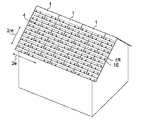
- FIG. 3 is a sectional view of the roofing material main body taken along line III-III in FIG. 1. It is a perspective view which shows the suspender of FIG. It is a perspective view which shows the 1st modification of the suspender of FIG. It is a perspective view which shows the 2nd modification of the suspender of FIG. It is a flowchart which shows the roof construction method by Embodiment 1 of this invention.
- Embodiment 1. 1 is a perspective view showing a metal roofing material 1 used in a roof construction method according to Embodiment 1 of the present invention
- FIG. 2 is an explanatory view showing an example in which the metal roofing material 1 of FIG. 1 is arranged on a roof surface
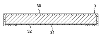
- 3 is a cross-sectional view of the roofing material main body 3 taken along the line III-III in FIG. 1
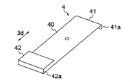
- FIG. 4 is a perspective view showing the hanger 4 of FIG.
- the metal roofing material 1 shown in FIG. 1 is a building member which is arranged on the roof surface of the building together with another metal roofing material 1 as shown in FIG. 2 and constitutes the roof structure of the building.
- FIG. 2 shows an example in which a plurality of metal roof materials 1 are arranged on the roof surface of a gable roof.
- the roof surface on which the metal roofing material 1 is arranged may be, for example, a roof surface of another roof having a slope such as a hipped roof or a roof of a purlin.
- roof surfaces are designed with varying slopes.
- building conditions such as the location of the building or the exterior design can be cited.
- each metal roofing material 1 is arranged so that a part of the metal roofing material 1 on the ridge side is overlapped with the metal roofing material 1 on the eaves side in the eaves direction 2re of the building.
- the width (width related to the eaves ridge direction 2re) in which the eaves side metal roofing material 1 is projected from the eaves side end portion of the ridge side metal roofing material 1 is called a working width.
- the eaves side metal roofing material 1 may be referred to as an eaves side roofing material 1E
- the ridge side metal roofing material 1 may be referred to as a ridge side roofing material 1R.
- eave-side roofing material 1E and ridge-side roofing material 1R are terms for distinguishing the two metal roofing materials 1 in the eaves-ridge direction 2re of the building, and are defined as specific positions in the entire roof. It is not prescribed.
- Another metal roofing material 1 may be arranged on the eaves side of the eaves side roofing material 1E, and another metal roofing material 1 may be arranged on the ridge side of the ridge side roofing material 1R.
- the metal roofing materials 1 are arranged so that the side edges of the metal roofing materials 1 abut each other with respect to the eaves direction 2e of the building.
- the ridge-side roof material 1R is arranged so as to be displaced from the eaves-side roof material 1E by half the width of the metal roof material 1 in the eaves direction 2e.
- the arrangement of the metal roofing material 1 in the eaves direction 2e of the building is not limited to the mode of FIG. 2 and other modes can be adopted.
- the metal roofing material 1 has a roofing material body 3 and a plurality of suspensions 4.
- the roofing material main body 3 of the present embodiment has a rectangular outer shape having a long side and a short side in a plan view.
- the direction in which the long side extends is called the width direction 3w
- the direction in which the short side extends is called the depth direction 3d.
- the depth direction 3d extends in the eaves ridge direction 2re of the roof
- the width direction 3w extends in the eaves direction 2e of the roof surface. It is adapted to be placed on the roof.
- the outer shape of the roofing material main body 3 may be a hexagonal shape in plan view as disclosed in JP-A-2018-003430.
- the roofing material main body 3 includes a front base material 30 made of a metal plate, a back base material 31 disposed on the back side of the front base material 30, and the front base material 30 and the back base material. It has a core material 32 filled between it and the material 31.
- the front base material 30 is a box-shaped metal plate having an opening on the back side, and is a member that appears on the outer surface of the roof when the metal roofing material 1 is placed on the roof surface.
- the metal plate that is a material of the front substrate 30 include a hot-dip Zn-plated steel sheet, a hot-dip Zn-Al alloy-plated steel sheet, a hot-dip Zn-Al-Mg alloy-plated steel sheet, a hot-dip Al-plated steel sheet, a hot-dip Zn-plated stainless steel sheet, a hot-dip Zn- sheet.
- the metal plate preferably has a thickness of 0.5 mm or less. As the thickness of the metal plate increases, the strength of the metal roofing material 1 increases while the weight increases. By setting the thickness of the metal plate to 0.5 mm or less, it is possible to prevent the weight of the metal roofing material 1 from becoming too large.
- the thickness of the metal plate is preferably 0.27 mm or more. By setting the thickness of the metal plate to 0.27 mm or more, the strength required for the metal roofing material 1 can be secured, and sufficient wind pressure resistance performance can be obtained.
- the wind pressure resistance performance is the performance that the metal roofing material 1 can withstand without being buckled against a strong wind.
- the back substrate 31 is arranged on the back side of the front substrate 30 so as to close the opening on the back side of the front substrate 30.
- a lightweight material such as aluminum foil, aluminum vapor-deposited paper, aluminum hydroxide paper, calcium carbonate paper, resin film or glass fiber paper can be used. By using these lightweight materials for the back substrate 31, it is possible to prevent the weight of the metal roofing material 1 from increasing. Further, as the back substrate 31, the same metal plate as the front substrate 30 may be used.
- the core material 32 is made of, for example, foam resin, and is filled between the front base material 30 and the back base material 31. By filling the core material 32 between the front base material 30 and the back base material 31, rather than a mode in which a backing material such as a resin sheet is attached to the back side of the front base material 30, inside the front base material 30.
- the core material 32 can be firmly adhered, and the performance required for the metal roof material 1 such as rain noise and heat insulation can be improved.
- a preformed plate-shaped heat insulating foam may be used as the core material 32.
- the material of the core material 32 is not particularly limited, and urethane, phenol, nurate resin, etc. can be used. However, it is desirable to use non-combustible certified materials for roofing materials. As the non-combustible material certification test, a heat generation test based on the ISO5660-1 cone calorimeter test method is carried out. When the foamed resin to be the core material 32 is urethane or the like that generates a large amount of heat, the thickness of the front substrate 30 as a whole can be reduced, or the foamed resin can contain inorganic foamed particles.
- the height of the internal space of the front substrate 30 filled with the core material 32 is preferably 4 mm or more and 8 mm or less.
- the strength of the front substrate 30 can be sufficiently increased, and the wind pressure resistance can be improved.
- the heat insulating property is also good when it is 4 mm or more.
- the height of the internal space is 8 mm or less, it is possible to prevent the organic mass of the core material 32 from becoming too large, and to obtain the non-combustible material certification more reliably.
- the driving display unit 33 is provided in the.
- the driving-in display portion 33 is configured to represent a position where a binding member such as a nail or a screw is driven into the metal roofing material 1.
- the drive-in display unit 33 of the present embodiment is formed by a concave portion having a circular shape in plan view.
- the driving-in display unit 33 can also adopt another mode in which the operator can visually or tactually recognize the driving position of the binding member, such as a protrusion, an opening, or a printed or engraved symbol.
- the suspenders 4 are spaced apart from each other in the width direction 3w of the roofing material main body 3 and are fastened to each other on one end side (ridge side) of the metal roofing material 1 in the depth direction 3d, such as screws or nails. It is tightly connected to the roofing material main body 3 by a member.
- the suspension 4 has a suspension main body 40, a first engagement portion 41, and a second engagement portion 42.
- the suspension body 40 is a flat plate portion extending in the depth direction 3d of the roof body 3.
- the first engaging portion 41 is a portion to be engaged with the ridge-side edge 3e of the roofing material body 3, and is provided on one end side of the hanging body 40 in the depth direction 3d.
- the first engaging portion 41 of the present embodiment is formed in an L-shaped cross section.
- the first engaging portion 41 is provided with a first engaging end surface 41a that abuts on the ridge-side end surface of the roofing material body 3.
- the second engaging portion 42 is provided on the other end side of the suspender body 40 in the depth direction 3d.
- the second engagement portion 42 of the present embodiment is formed in a U-shaped cross section.
- the eaves-side end of the ridge-side roof material 1R is engaged with the second engagement portion 42.
- the second engaging portion 42 is provided with a second engaging end surface 42a that comes into contact with the eave-side end surface of the ridge-side roofing material 1R.
- FIG. 5 is a perspective view showing a first modification of the suspension 4 of FIG. 4
- FIG. 6 is a perspective view showing a second modification of the suspension 4 of FIG.
- the suspension 4 of the first modification shown in FIG. 5 has a shorter length of the suspension main body 40 (distance between the first and second engagement end faces 41a, 42a) than that of the suspension 4 shown in FIG.
- the length of the suspension main body 40 is shorter than that of the suspension 4 of the first modification shown in FIG.
- the position of the second engaging portion 42 from the ridge-side edge of the roofing material body 3 is defined by the first engaging portion 41 and the suspender body 40.
- the working width of the eaves-side roofing material 1E or the overlapping width of the eaves-side roofing material 1E and the ridge-side roofing material 1R is increased. Decided. That is, as shown in FIG. 4 to FIG. 6, the working width of the eaves side roofing material 1E can be changed by using the suspensions 4 having different lengths of the suspension body 40.
- FIG. 7 is a flowchart showing a roof construction method according to the first embodiment of the present invention.
- the roof construction method of the present embodiment corresponds to a method (roof manufacturing method) for manufacturing a roof as shown in FIG. 2 using the metal roof material 1 shown in FIG.
- the roof manufacturing method of the embodiment includes a working width determination step (step S1), a suspension selection and attachment step (step S2), and a roof material placement step (step S3). ing.
- the working width of the eaves-side roofing material 1E is adjusted according to the slope of the roof surface so that the horizontal projection dimension obtained by projecting the working width of the eaves-side roofing material 1E on a horizontal plane is constant. To decide.
- the roof surface is designed with different slopes.
- the working width of the eaves side roofing material 1E is determined so that the first roof surface having the first slope and the second roof surface having the second slope have the same horizontal projection dimension. To do.
- the working width W is determined according to the inclination angle ⁇ so that the horizontal projection dimension H takes a constant value.
- step S2 In the step of selecting and attaching the sling (step S2), a predetermined value is obtained from the ridge-side edge 3e of the eaves-side roofing material 1E in the depth direction 3d so as to obtain the working width W determined in the step of determining the working width (step S1).
- the hanger 4 with which the eaves side end of the ridge-side roofing material 1R is engaged is selected at a position spaced apart by the dimension. Specifically, the hanger 4 having the length of the hanger body 40 corresponding to the determined working width W (distance between the first and second engagement end faces 41a, 42a) is selected. Further, in the step of selecting and attaching the sling (step S2), the selected sling 4 is attached to the roof material main body 3 to form the metal roof material 1 shown in FIG.
- the selected suspenders 4 are described as being attached to the roof material main body 3, a plurality of types of metal roofs to which the suspenders 4 having different lengths of the suspension body 40 are attached.
- the material 1 is prepared in advance, and the metal roofing material 1 to which the suspension 4 corresponding to the working width W determined in the working width determining step (step S1) is attached is selected from a plurality of types of metal roofing materials 1. You may.
- step S3 the metal roofing material 1 to which the suspenders 4 are attached in the step of selecting and attaching the suspenders (step S2) is placed on the roof surface to form the roof shown in FIG.
- step S3 while engaging the eaves side end portion of the ridge-side roof material 1R with the second engaging portion 42 of the suspension 4 of the eaves-side roof material 1E, the ridge-side roof material 1R The eaves side edge part is piled up and arranged.
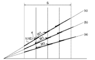
- FIG. 8 is an explanatory view showing an embodiment in which the working width of the eaves side roofing material 1E is determined according to the inclination of the roof surface so that the horizontal projection dimension is constant
- FIG. 9 is concerned with the inclination of the roof surface. It is explanatory drawing which shows the comparative example in which the working width of the roof eaves side roofing material 1E was made constant. When the metal roofing material 1 is actually arranged on the roof surface, a slight difference occurs between the slope of the roof surface and the slope of the metal roofing material 1, but this difference is small enough to be ignored.
- a roof slope of 3 inches means a slope having a horizontal dimension of 10 inches and a rising dimension of 3 inches.
- One dimension is 1/33 m (about 30.303 mm).
- a 3 inch roof slope is 16.6992 degrees in angle
- a 4.5 inch roof slope is 24.2277 degrees in angle
- a 6 inch roof slope is 30.9638 degrees in angle. ..
- the horizontal projection dimension H can be made constant by increasing the working width in accordance with the increase in the roof slope. Assuming that the working widths are W1 to W3 when the roof pitch is 3, 4, and 6 inches, respectively, the relationship W1 ⁇ W2 ⁇ W3 is established when the horizontal projection dimension H is set to a constant dimension.
- the section S can be covered with four metal roof materials 1 regardless of the roof slope. That is, the working width of the eaves side roofing material 1E is determined according to the slope of the roof surface so that the horizontal projection dimension H obtained by projecting the working width of the eaves side roofing material 1E on a horizontal plane becomes a constant dimension. It is possible to avoid changing the number of steps of the metal roofing material to be arranged on the roof surface due to the slope.
- the eaves side roofing material is adjusted according to the slope of the roof surface so that the horizontal projection dimension H obtained by projecting the working width of the eaves side roofing material 1E on the horizontal plane becomes a constant dimension. Since the working width of 1E is determined, it is possible to avoid changing the number of steps of the metal roofing material 1 to be arranged on the roof surface due to the slope of the roof surface.
- the ridge-side roofing material 1R at a position separated from the ridge-side edge 3e of the eaves-side roofing material 1E by a predetermined dimension in the depth direction 3d.
- the eaves side end portion of the eaves side end portion is attached to the eaves side roofing material 1E, so that the eaves side end portion of another metal roofing material 1 (ridge side roofing material 1R) is engaged with the hangings 4
- the metal roofing material 1 so that the horizontal projection dimension becomes a constant dimension only by itself, and it is possible to more easily avoid changing the number of steps of the metal roofing material 1 to be arranged on the roof surface due to the slope of the roof surface.
- the suspension 4 since the suspension 4 has the suspension main body 40, the 1st engaging part 41, and the 2nd engaging part 42, by changing the length of the suspension main body 40, the eaves side roofing material 1E.
- the working width of can be more reliably changed, and more reliably the slope of the roof surface can be prevented from changing the number of steps of the metal roofing material 1 to be arranged on the roof surface.
- FIG. 10 is a perspective view which shows the metal roofing material 1 used for the roof construction method by Embodiment 2 of this invention.
- the first to third display parts 51, 52 showing the position where the eaves side edge of another metal roofing material 1 (ridge side roofing material 1R) should be aligned according to the slope of the roof surface.
- 53 plural of display parts
- the first to third display parts 51, 52, 53 are arranged apart from each other in the depth direction 3d.
- the first display section 51 can be used for a 3-inch roof slope
- the second display section 52 can be used for a 4.5-inch roof slope
- the third display section 53 can be used for a 6-inch roof slope.
- the number of such display units may be two or four or more.
- the first to third display parts 51, 52, 53 may be provided in a part of the roofing material main body 3 in the width direction 3w, but extend over the entire roofing material main body 3 in the width direction 3w. It is preferable. This is because the eaves side edge of another metal roofing material 1 (ridge-side roofing material 1R) can be more surely matched.
- the first to third display parts 51, 52, 53 can be configured by one or a plurality of protrusions linearly extending along the width direction 3w.
- the plurality of protrusions forming the first to third display portions 51, 52, 53 are arranged apart from each other in the width direction 3w.
- the positions where the parts are separated from each other are preferably aligned with each other. That is, it is preferable that the flat portions between the protrusions are arranged linearly in the depth direction 3d. Since the positions where the protrusions are separated from each other are aligned with each other, the obstruction of the water flow due to the protrusions can be suppressed.
- the first to third display parts 51, 52, 53 are, for example, recesses or printed or engraved symbols or the like at positions where the eaves side edges of another metal roofing material 1 (ridge side roofing material 1R) should be aligned. It is also possible to adopt another mode in which the worker can visually or tactually recognize.
- the driving-in display portion 33 is also provided at a position located on the ridge side when the metal roofing material 1 is placed on the roof surface.
- Other configurations are similar to those of the metal roofing material 1 of the first embodiment.
- FIG. 11 is a flowchart showing a roof construction method according to the second embodiment of the present invention.
- the roof construction method according to the first embodiment includes the step of selecting and attaching the sling (step S2). However, in the roof construction method according to the second embodiment, the step of selecting and attaching the sling (step S2) is omitted.
- the roof material arranging step (step S3) the metal roof material 1 is arranged based on the first to third display portions 51 to 53 for obtaining the working width W determined in the working width determining step (step S1).
- Other configurations are the same as the roof construction method of the first embodiment.
- the eaves-side edge of another metal roofing material 1 is arranged apart from each other in the depth direction 3d according to the slope of the roof surface. Since the first to third display parts 51 to 53 (plurality of display parts) indicate the positions where the positions should be adjusted, the eave side edge of another metal roofing material 1 can be set to one of the first to third display parts 51 to 53. It is possible to arrange the metal roofing material 1 so that the horizontal projected dimension becomes a constant dimension only by adjusting to, and it is possible to more easily avoid changing the number of steps of the metal roofing material to be arranged on the roof surface due to the slope of the roof surface. ..
- the suspension 4 described in the first embodiment may be attached to the metal roof material 1 of the second embodiment.
Landscapes
- Engineering & Computer Science (AREA)
- Architecture (AREA)
- Civil Engineering (AREA)
- Structural Engineering (AREA)
- Mechanical Engineering (AREA)
- Roof Covering Using Slabs Or Stiff Sheets (AREA)
Abstract
本発明による屋根施工方法は、屋根面の上に複数の金属屋根材を配置する屋根施工方法であって、金属屋根材には、軒側屋根材と、軒側屋根材に重ねて配置される棟側屋根材とが含まれており、軒側屋根材の働き幅を水平面に投影した水平投影寸法が一定寸法となるように、屋根面の勾配に応じて軒側屋根材の働き幅を決定する工程(ステップS1)を含む。
Description
本発明は、屋根面の上に複数の金属屋根材を配置する屋根施工方法及びそれに用いる金属屋根材に関する。
下記の特許文献1には、平板状の金属屋根材が開示されている。金属屋根材は、奥行方向が屋根面の軒棟方向に延在するように屋根面の上に配置されるとともに、奥行方向の一端側(棟側)に別の金属屋根材が重ねて配置されるように適合されている。また、特許文献1では、金属屋根材の表面に表示部を設けておき、その表示部を基準に棟側の金属屋根材を軒側の金属屋根材に重ねて配置することで、軒側の金属屋根材の働き幅を一定幅とすることも提案されている。働き幅とは、棟側の金属屋根材に覆われずに、棟側の金属屋根材の軒側で露出される奥行方向に係る軒側の金属屋根材の幅である。
上記のような従来構成では、軒側の金属屋根材の一定幅とするので、以下のような問題が生じる。すなわち、建築物の屋根面は様々な勾配を有するように設計される。従来構成のように軒側の金属屋根材の一定幅とすると、屋根面の勾配により屋根面に配置すべき金属屋根材の段数を変える必要がある。金属屋根材の段数が変わると、屋根の施工に必要とされる金属屋根材の枚数も変わってしまう。
本発明は、上記のような課題を解決するためになされたものであり、その目的は、屋根面の勾配により屋根面に配置すべき金属屋根材の段数が変わることを回避できる屋根施工方法及びそれに用いる金属屋根材を提供する。
本発明に係る屋根施工方法は、屋根面の上に複数の金属屋根材を配置する屋根施工方法であって、金属屋根材には、軒側屋根材と、軒側屋根材に重ねて配置される棟側屋根材とが含まれており、軒側屋根材の働き幅を水平面に投影した水平投影寸法が一定寸法となるように、屋根面の勾配に応じて軒側屋根材の働き幅を決定する工程を含む。
本発明に係る金属屋根材は、奥行方向が屋根面の軒棟方向に延在するように屋根面の上に配置されるとともに、奥行方向の一端側に別の金属屋根材が重ねて配置されるように適合された金属屋根材であって、奥行方向の一端に配置された棟側端縁と、屋根面の勾配に応じて決定された所定の寸法だけ奥行方向に関して棟側端縁から離れた位置で別の金属屋根材の軒側端部が係合される吊子とを備える。
本発明に係る金属屋根材は、奥行方向が屋根面の軒棟方向に延在するように屋根面の上に配置されるとともに、奥行方向の一端側に別の金属屋根材が重ねて配置されるように適合された金属屋根材であって、奥行方向に互いに離間して配置されるとともに、屋根面の勾配に応じて別の金属屋根材の軒側端縁を合わせるべき位置を示す複数の表示部を備える。
本発明の屋根施工方法によれば、軒側屋根材の働き幅を水平面に投影した水平投影寸法が一定寸法となるように、屋根面の勾配に応じて軒側屋根材の働き幅を決定するので、屋根面の勾配により屋根面に配置すべき金属屋根材の段数が変わることを回避できる。
本発明の金属屋根材によれば、屋根面の勾配に応じて決定された所定の寸法だけ奥行方向に関して棟側端縁から離れた位置で別の金属屋根材の軒側端部に吊子が係合されるので、別の金属屋根材の軒側端部を吊子に係合させるだけで水平投影寸法が一定寸法となるように金属屋根材を配置することができ、屋根面の勾配により屋根面に配置すべき金属屋根材の段数が変わることをより容易に回避できる。
本発明の金属屋根材によれば、奥行方向に互いに離間して配置されるとともに、屋根面の勾配に応じて別の金属屋根材の軒側端縁を合わせるべき位置を複数の表示部が示すので、別の金属屋根材の軒側端縁を表示部のいずれかに合わせるだけで水平投影寸法が一定寸法となるように金属屋根材を配置することができ、屋根面の勾配により屋根面に配置すべき金属屋根材の段数が変わることをより容易に回避できる。
以下、本発明を実施するための形態について、図面を参照して説明する。本発明は各実施の形態に限定されるものではなく、その要旨を逸脱しない範囲で構成要素を変形して具体化できる。また、各実施形態に開示されている複数の構成要素の適宜な組み合わせにより、種々の発明を形成できる。例えば、実施の形態に示される全構成要素からいくつかの構成要素を削除してもよい。さらに、異なる実施形態の構成要素を適宜組み合わせてもよい。
実施の形態1.
図1は本発明の実施の形態1による屋根施工方法に用いる金属屋根材1を示す斜視図であり、図2は図1の金属屋根材1が屋根面上に配置された例を示す説明図であり、図3は図1の線III-IIIに沿う屋根材本体3の断面図であり、図4は図1の吊子4を示す斜視図である。
図1は本発明の実施の形態1による屋根施工方法に用いる金属屋根材1を示す斜視図であり、図2は図1の金属屋根材1が屋根面上に配置された例を示す説明図であり、図3は図1の線III-IIIに沿う屋根材本体3の断面図であり、図4は図1の吊子4を示す斜視図である。
図1に示す金属屋根材1は、図2に示すように別の金属屋根材1とともに建物の屋根面の上に配置されて、建物の屋根構造を構成する建築部材である。図2では、複数の金属屋根材1が切妻屋根の屋根面に配置された例を示している。金属屋根材1が配置される屋根面は、例えば寄棟屋根又は入母屋屋根等の勾配を有する他の屋根の屋根面であってもよい。周知のように、屋根面は様々な勾配を有するように設計される。屋根面の勾配を決める要素としては、例えば建物の立地等の建築条件又は外観デザインを挙げることができる。
図2に示すように、各金属屋根材1は、建物の軒棟方向2reに関して軒側の金属屋根材1に棟側の金属屋根材1の一部が重ねられるように配置されている。棟側の金属屋根材1の軒側端部から軒側の金属屋根材1が突出されている幅(軒棟方向2reに係る幅)は、働き幅と呼ばれる。軒側の金属屋根材1を軒側屋根材1Eと呼び、棟側の金属屋根材1を棟側屋根材1Rと呼ぶことがある。これら軒側屋根材1E及び棟側屋根材1Rとの用語は、建物の軒棟方向2reに係る2つの金属屋根材1を区別するための用語であり、屋根全体の中での特定の位置を規定するものではない。軒側屋根材1Eの軒側に別の金属屋根材1が配置されていてよく、棟側屋根材1Rの棟側に別の金属屋根材1が配置されていてよい。
各金属屋根材1は、建物の軒方向2eに関して互いの側端を突き合せるように配置されている。棟側屋根材1Rは、軒側屋根材1Eに対して金属屋根材1の幅の半分だけ軒方向2eにずれて配置されている。但し、建物の軒方向2eに係る金属屋根材1の配置は、図2の態様に限定されず、他の態様を採ることができる。
図1に示すように、金属屋根材1は、屋根材本体3と複数の吊子4とを有している。
本実施の形態の屋根材本体3は、長辺及び短辺を有する平面視矩形の外形を有している。長辺が延在する方向を幅方向3wと呼び、短辺が延在する方向を奥行方向3dと呼ぶこととする。図2に示すように、本実施の形態の金属屋根材1は、奥行方向3dが屋根の軒棟方向2reに延在し、幅方向3wが屋根面の軒方向2eに延在するように、屋根面に配置されるように適合されている。なお、屋根材本体3の外形は、特開2018-003430号公報に示されるような平面視六角形であってもよい。
図3に特に表れているように、屋根材本体3は、金属板を素材とする表基材30、表基材30の裏側に配置された裏基材31、及び表基材30と裏基材31との間に充填された芯材32を有している。
表基材30は、裏側に開口を有する箱形に金属板が成形されたものであり、金属屋根材1が屋根面の上に配置された際に屋根の外面に現れる部材である。表基材30の素材である金属板としては、溶融Znめっき鋼板、溶融Zn-Al合金めっき鋼板、溶融Zn-Al-Mg合金めっき鋼板、溶融Alめっき鋼板、溶融Znめっきステンレス鋼板、溶融Zn-Al合金めっきステンレス鋼板、溶融Zn-Al-Mg合金めっきステンレス鋼板、溶融Alめっきステンレス鋼板、ステンレス鋼板、Al板、Ti板、塗装溶融Znめっき鋼板、塗装溶融Zn-Al合金めっき鋼板、塗装溶融Zn-Al-Mg合金めっき鋼板、塗装溶融Alめっき鋼板、塗装溶融Zn系めっきステンレス鋼板、塗装溶融Alめっきステンレス鋼板、塗装ステンレス鋼板、塗装Al板又は塗装Ti板を用いることができる。
金属板の厚みは0.5mm以下であることが好ましい。金属板の厚みの増加に伴い、金属屋根材1の強度が増大する一方で重量が増す。金属板の厚みを0.5mm以下とすることで、金属屋根材1の重量が大きくなりすぎることを回避できる。なお、金属板の厚みは0.27mm以上であることが好ましい。金属板の厚みを0.27mm以上とすることで、金属屋根材1として必要とされる強度を確保でき、耐風圧性能を十分に得ることができる。耐風圧性能とは、強い風に対して座屈せずに金属屋根材1が耐えられる性能である。
裏基材31は、表基材30の裏側の開口を塞ぐように表基材30の裏側に配置されている。裏基材31としては、アルミ箔、アルミ蒸着紙、水酸化アルミ紙、炭酸カルシウム紙、樹脂フィルム又はガラス繊維紙等の軽量な素材を用いることができる。これらの軽量な素材を裏基材31に用いることで、金属屋根材1の重量が増大することを回避することができる。また、裏基材31として、表基材30を構成する金属板と同様のものを使用してもよい。
芯材32は、例えば発泡樹脂等により構成されるものであり、表基材30と裏基材31との間に充填されている。表基材30と裏基材31との間に芯材32が充填されることで、樹脂シート等の裏打ち材を表基材30の裏側に張り付ける態様よりも、表基材30の内部に芯材32を強固に密着させることができ、雨音性、断熱性等の金属屋根材1に求められる性能を向上させることができる。芯材32として、予め成形された板状の断熱フォームを使用してもよい。
芯材32の素材としては、特に制限が無く、ウレタン、フェノール、ヌレート樹脂等を用いることができる。ただし、屋根材においては不燃認定材料を使用することが望ましい。不燃材料認定試験は、ISO5660-1コーンカロリーメーター試験法に準拠した発熱性試験が実施される。芯材32となる発泡樹脂が発熱量の多いウレタンなどの場合は、表基材30の全体としての厚みを薄くしたり、発泡樹脂に無機発泡粒子を含有させたりすることができる。
芯材32が充填される表基材30の内部空間の高さは、4mm以上かつ8mm以下とされることが好ましい。内部空間の高さを4mm以上とすることで、表基材30の強度を十分に高くすることができ、耐風圧性を向上させることができる。断熱性についても4mm以上で良好となる。また、内部空間の高さを8mm以下とすることで、芯材32の有機質量が多くなりすぎることを回避して、より確実に不燃材料認定を得ることができるようにしている。
図1に戻り、表基材30の表面には、屋根材本体3の幅方向3wに係る両側であって、金属屋根材1が屋根面の上に配置された際に軒側に位置する場所に打込表示部33が設けられている。打込表示部33は、例えば釘又はビス等の緊結部材を金属屋根材1に打ち込む位置を表すための構成である。本実施の形態の打込表示部33は、平面視円形の凹部により構成されている。しかしながら、打込表示部33は、例えば突体、開口又は印刷若しくは刻設された記号等、緊結部材の打込み位置を作業者が視覚的又は触覚的に認識できる他の態様を採ることもできる。
<吊子について>
図1に示すように、吊子4は、屋根材本体3の幅方向3wに互いに離間して、金属屋根材1の奥行方向3dに係る一端側(棟側)において例えばビス又は釘等の緊結部材により屋根材本体3に緊結されている。
図1に示すように、吊子4は、屋根材本体3の幅方向3wに互いに離間して、金属屋根材1の奥行方向3dに係る一端側(棟側)において例えばビス又は釘等の緊結部材により屋根材本体3に緊結されている。
図4に示すように、吊子4は、吊子本体40、第1係合部41及び第2係合部42を有している。
吊子本体40は、屋根材本体3の奥行方向3dに延在される平板部分である。
第1係合部41は、屋根材本体3の棟側端縁3eに係合されるための部分であり、奥行方向3dに係る吊子本体40の一端側に設けられている。本実施の形態の第1係合部41は、断面L字状に形成されている。第1係合部41には、屋根材本体3の棟側の端面に当接される第1係合端面41aが設けられている。
第2係合部42は、奥行方向3dに係る吊子本体40の他端側に設けられている。本実施の形態の第2係合部42は、断面コ字状に形成されている。第2係合部42には棟側屋根材1Rの軒側端部が係合される。第2係合部42には、棟側屋根材1Rの軒側の端面に当接される第2係合端面42aが設けられている。
次に、図5は図4の吊子4の第1変形例を示す斜視図であり、図6は図4の吊子4の第2変形例を示す斜視図である。図5に示す第1変形例の吊子4は、図4に示す吊子4よりも吊子本体40の長さ(第1及び第2係合端面41a,42a間の離間距離)が短い。図6に示す第2変形例の吊子4は、図5に示す第1変形例の吊子4よりも吊子本体40の長さが短い。屋根材本体3の棟側端縁からの第2係合部42の位置は、第1係合部41及び吊子本体40によって規定される。第2係合部42に棟側屋根材1Rの軒側端部が係合されることで、軒側屋根材1Eの働き幅又は軒側屋根材1Eと棟側屋根材1Rとの重なり幅が決まる。すなわち、図4~図6に示すように吊子本体40の長さが異なる吊子4を用いることで、軒側屋根材1Eの働き幅を変更することができる。
次に、図7は、本発明の実施の形態1による屋根施工方法を示すフローチャートである。本実施の形態の屋根施工方法は、図1に示す金属屋根材1を用いて図2に示すような屋根を製造するための方法(屋根の製造方法)に相当する。図7に示すように、実施の形態の屋根製造方法には、働き幅の決定工程(ステップS1)、吊子の選定及び取付工程(ステップS2)及び屋根材配置工程(ステップS3)が含まれている。
働き幅の決定工程(ステップS1)では、軒側屋根材1Eの働き幅を水平面に投影した水平投影寸法が一定寸法となるように、屋根面の勾配に応じて軒側屋根材1Eの働き幅を決定する。上述のように、屋根面は様々な勾配を有するように設計される。本実施の形態の屋根施工方法では、第1勾配を有する第1屋根面と第2勾配を有する第2屋根面とで同一の水平投影寸法を有するように軒側屋根材1Eの働き幅を決定する。水平面に対する軒側屋根材1Eの傾斜角度をθとし、軒側屋根材1Eの働き幅をWとした場合、水平投影寸法Hは、H=W・cosθにより表される。水平投影寸法Hが一定値を採るように、傾斜角度θに応じて働き幅Wが決定される。
吊子の選定及び取付工程(ステップS2)では、働き幅の決定工程(ステップS1)で決定した働き幅Wを得るように、奥行方向3dに関して軒側屋根材1Eの棟側端縁3eから所定の寸法だけ離れた位置で棟側屋根材1Rの軒側端部が係合される吊子4が選定される。具体的には、決定した働き幅Wに対応する吊子本体40の長さ(第1及び第2係合端面41a,42a間の離間距離)を有する吊子4が選定される。また、吊子の選定及び取付工程(ステップS2)では、選定された吊子4を屋根材本体3に取り付けて、図1に示す金属屋根材1を形成する。
なお、本実施の形態では、選定された吊子4を屋根材本体3に取り付けるように説明しているが、吊子本体40の長さが異なる吊子4が取り付けられた複数種類の金属屋根材1を予め準備しておき、働き幅の決定工程(ステップS1)で決定した働き幅Wに対応する吊子4が取り付けられた金属屋根材1を複数種類の金属屋根材1の中から選定してもよい。
屋根材配置工程(ステップS3)では、吊子の選定及び取付工程(ステップS2)で吊子4が取り付けられた金属屋根材1を屋根面に配置して図2に示す屋根を形成する。このとき、軒側屋根材1Eの吊子4の第2係合部42に棟側屋根材1Rの軒側端部を係合させつつ、軒側屋根材1Eの上に棟側屋根材1Rの軒側端部を重ねて配置する。
次に、水平投影寸法を一定寸法とした場合の作用効果について説明する。図8は水平投影寸法が一定寸法となるように屋根面の勾配に応じて軒側屋根材1Eの働き幅が決定された実施例を示す説明図であり、図9は屋根面の勾配に拘わらず軒側屋根材1Eの働き幅が一定とされた比較例を示す説明図である。なお、実際に金属屋根材1を屋根面上に配置すると、屋根面の勾配と金属屋根材1の勾配との間に僅かな差異が生じるが、この差異は無視できる程度に小さい。
図8及び図9において、(a)は屋根勾配が3寸の場合を示し、(b)は屋根勾配が4.5寸の場合を示し、(c)は屋根勾配が6寸の場合を示している。例えば、3寸の屋根勾配とは、水平寸法が10寸に対して立ち上がり寸法が3寸の勾配を意味している。1寸は、1/33m(約30.303mm)である。3寸の屋根勾配を角度で表すと16.6992度となり、4.5寸の屋根勾配を角度で表すと24.2277度となり、6寸の屋根勾配を角度で表すと30.9638度となる。
図8に示すように、水平投影寸法Hが一定寸法となるように屋根面の勾配に応じて軒側屋根材1Eの働き幅を決定した場合、屋根勾配に応じて軒側屋根材1Eの働き幅が変わる。換言すると、屋根勾配の増大に応じて働き幅を増大させることにより、水平投影寸法Hを一定寸法とすることができる。3寸、4.5寸及び6寸の屋根勾配のときのそれぞれの働き幅をW1~W3とすると、水平投影寸法Hを一定寸法としたときW1<W2<W3の関係が成り立つ。
図8に示す実施例では、屋根勾配に拘わらず区間Sを4枚の金属屋根材1でカバーできている。すなわち、軒側屋根材1Eの働き幅を水平面に投影した水平投影寸法Hが一定寸法となるように、屋根面の勾配に応じて軒側屋根材1Eの働き幅を決定するので、屋根面の勾配により屋根面に配置すべき金属屋根材の段数が変わることを回避できる。
これに対して、図9に示すように、屋根面の勾配に拘わらず軒側屋根材1Eの働き幅Wを一定とした場合、3寸の屋根勾配(図9の(a))のときには区間Sを4枚の金属屋根材1でカバーできているが、6寸の屋根勾配(図9の(c))のときには区間Sを4枚の金属屋根材1でカバーできていない。すなわち、屋根面の勾配により屋根面に配置すべき金属屋根材の段数が変わってしまう。
本実施の形態のような屋根施工方法によれば、軒側屋根材1Eの働き幅を水平面に投影した水平投影寸法Hが一定寸法となるように、屋根面の勾配に応じて軒側屋根材1Eの働き幅を決定するので、屋根面の勾配により屋根面に配置すべき金属屋根材1の段数が変わることを回避できる。
また、本実施の形態のような屋根施工方法及び金属屋根材1によれば、奥行方向3dに関して軒側屋根材1Eの棟側端縁3eから所定の寸法だけ離れた位置で棟側屋根材1Rの軒側端部が係合される吊子4が軒側屋根材1Eに取り付けられるので、別の金属屋根材1(棟側屋根材1R)の軒側端部を吊子4に係合させるだけで水平投影寸法が一定寸法となるように金属屋根材1を配置することができ、屋根面の勾配により屋根面に配置すべき金属屋根材1の段数が変わることをより容易に回避できる。
また、吊子4が、吊子本体40、第1係合部41及び第2係合部42を有しているので、吊子本体40の長さを変更することにより、軒側屋根材1Eの働き幅をより確実に変更することができ、より確実に屋根面の勾配により屋根面に配置すべき金属屋根材1の段数が変わることを回避できる。
実施の形態2.
図10は、本発明の実施の形態2による屋根施工方法に用いる金属屋根材1を示す斜視図である。実施の形態1では、異なる吊子4を用いることにより、軒側屋根材1Eの働き幅を変更できるように説明した。一方、図10に示すように、屋根面の勾配に応じて別の金属屋根材1(棟側屋根材1R)の軒側端縁を合わせるべき位置を示す第1~第3表示部51,52,53(複数の表示部)を金属屋根材1の表基材30の表面に設けておき、これら第1~第3表示部51,52,53に基づき軒側屋根材1Eの働き幅を変更してもよい。
図10は、本発明の実施の形態2による屋根施工方法に用いる金属屋根材1を示す斜視図である。実施の形態1では、異なる吊子4を用いることにより、軒側屋根材1Eの働き幅を変更できるように説明した。一方、図10に示すように、屋根面の勾配に応じて別の金属屋根材1(棟側屋根材1R)の軒側端縁を合わせるべき位置を示す第1~第3表示部51,52,53(複数の表示部)を金属屋根材1の表基材30の表面に設けておき、これら第1~第3表示部51,52,53に基づき軒側屋根材1Eの働き幅を変更してもよい。
第1~第3表示部51,52,53は、奥行方向3dに互いに離間して配置されている。第1表示部51を3寸の屋根勾配用とし、第2表示部52を4.5寸の屋根勾配用とし、第3表示部53を6寸の屋根勾配用とすることができる。このような表示部の数は、2又は4以上であってもよい。
第1~第3表示部51,52,53は、幅方向3wに関して屋根材本体3の一部に設けられていてもよいが、幅方向3wに関して屋根材本体3の全体に延在されていることが好ましい。別の金属屋根材1(棟側屋根材1R)の軒側端縁をより確実に合わせることができるためである。第1~第3表示部51,52,53は、幅方向3wに沿って直線状に延在された1つ又は複数の突部により構成することができる。第1~第3表示部51,52,53を構成する複数の突部は、幅方向3wに互いに離間して配置される。第1表示部51を構成する複数の突部が互いに離間される位置、第2表示部52を構成する複数の突部が互いに離間される位置、及び第3表示部53を構成する複数の突部が互いに離間される位置は互いに合わされていることが好ましい。すなわち、突部間の平坦部が奥行方向3dに直線状に並べて配置されていることが好ましい。突部が互いに離間される位置が互いに合わされることで、突部による水の流れの阻害を抑えることができる。なお、第1~第3表示部51,52,53は、例えば凹部又は印刷若しくは刻設された記号等、別の金属屋根材1(棟側屋根材1R)の軒側端縁を合わせるべき位置を作業者が視覚的又は触覚的に認識できる他の態様を採ることもできる。
本実施の形態2の金属屋根材1には、金属屋根材1が屋根面の上に配置された際に棟側に位置する場所にも打込表示部33が設けられている。その他の構成は、実施の形態1の金属屋根材1と同様である。
次に、図11は、本発明の実施の形態2による屋根施工方法を示すフローチャートである。実施の形態1の屋根施工方法では、吊子の選定及び取付工程(ステップS2)が含まれていた。しかしながら、実施の形態2による屋根施工方法では、吊子の選定及び取付工程(ステップS2)が省略される。屋根材配置工程(ステップS3)では、働き幅の決定工程(ステップS1)で決定した働き幅Wを得る第1~第3表示部51~53を基準に金属屋根材1を配置する。その他の構成は、実施の形態1の屋根施工方法と同様である。
本実施の形態のような屋根施工方法及び金属屋根材1によれば、奥行方向3dに互いに離間して配置されるとともに、屋根面の勾配に応じて別の金属屋根材1の軒側端縁を合わせるべき位置を第1~第3表示部51~53(複数の表示部)が示すので、別の金属屋根材1の軒側端縁を第1~第3表示部51~53のいずれかに合わせるだけで水平投影寸法が一定寸法となるように金属屋根材1を配置することができ、屋根面の勾配により屋根面に配置すべき金属屋根材の段数が変わることをより容易に回避できる。
なお、実施の形態2の金属屋根材1に実施の形態1で説明した吊子4が取り付けられていてもよい。
Claims (7)
- 屋根面の上に複数の金属屋根材を配置する屋根施工方法であって、前記金属屋根材には、軒側屋根材と、前記軒側屋根材に重ねて配置される棟側屋根材とが含まれており、
前記軒側屋根材の働き幅を水平面に投影した水平投影寸法が一定寸法となるように、前記屋根面の勾配に応じて前記軒側屋根材の働き幅を決定する工程
を含む、
屋根施工方法。 - 前記金属屋根材は、奥行方向が前記屋根面の軒棟方向に延在するように前記屋根面の上に配置されるように適合されており、
前記軒側屋根材には、前記決定された働き幅を得るように、前記奥行方向に関して前記軒側屋根材の棟側端縁から所定の寸法だけ離れた位置で前記棟側屋根材の軒側端部が係合される吊子が取り付けられている、
請求項1記載の屋根施工方法。 - 前記吊子は、
前記奥行方向に延在される吊子本体と、
前記奥行方向に係る前記吊子本体の一端側に設けられ、前記軒側屋根材の前記棟側端縁に係合される第1係合部と、
前記奥行方向に係る前記吊子本体の他端側に設けられ、前記棟側屋根材の前記軒側端部に係合される第2係合部と
を有している、
請求項2記載の屋根施工方法。 - 前記金属屋根材は、奥行方向が前記屋根面の軒棟方向に延在するように前記屋根面の上に配置されるように適合されており、
前記金属屋根材には、前記奥行方向に互いに離間して配置されるとともに、前記屋根面の勾配に応じて前記棟側屋根材の軒側端縁を合わせるべき位置を示す複数の表示部が設けられている、
請求項1から請求項3までのいずれか一項に記載の屋根施工方法。 - 奥行方向が屋根面の軒棟方向に延在するように前記屋根面の上に配置されるとともに、前記奥行方向の一端側に別の金属屋根材が重ねて配置されるように適合された金属屋根材であって、
前記奥行方向の一端に配置された棟側端縁と、
前記屋根面の勾配に応じて決定された所定の寸法だけ前記奥行方向に関して前記棟側端縁から離れた位置で前記別の金属屋根材の軒側端部が係合される吊子と
を備える、金属屋根材。 - 前記吊子は、
前記奥行方向に延在される吊子本体と、
前記奥行方向に係る前記吊子本体の一端側に設けられ、前記棟側端縁に係合される第1係合部と、
前記奥行方向に係る前記吊子本体の他端側に設けられ、前記別の金属屋根材の前記軒側端部に係合される第2係合部と
を有している、
請求項5記載の金属屋根材。 - 奥行方向が屋根面の軒棟方向に延在するように屋根面の上に配置されるとともに、前記奥行方向の一端側に別の金属屋根材が重ねて配置されるように適合された金属屋根材であって、
前記奥行方向に互いに離間して配置されるとともに、前記屋根面の勾配に応じて前記別の金属屋根材の軒側端縁を合わせるべき位置を示す複数の表示部
を備えている、金属屋根材。
Applications Claiming Priority (2)
| Application Number | Priority Date | Filing Date | Title |
|---|---|---|---|
| JP2019-019096 | 2019-02-05 | ||
| JP2019019096A JP7295379B2 (ja) | 2019-02-05 | 2019-02-05 | 屋根施工方法 |
Publications (1)
| Publication Number | Publication Date |
|---|---|
| WO2020162055A1 true WO2020162055A1 (ja) | 2020-08-13 |
Family
ID=71947599
Family Applications (1)
| Application Number | Title | Priority Date | Filing Date |
|---|---|---|---|
| PCT/JP2019/049673 Ceased WO2020162055A1 (ja) | 2019-02-05 | 2019-12-18 | 屋根施工方法及びそれに用いる金属屋根材 |
Country Status (3)
| Country | Link |
|---|---|
| JP (1) | JP7295379B2 (ja) |
| TW (1) | TW202031976A (ja) |
| WO (1) | WO2020162055A1 (ja) |
Families Citing this family (2)
| Publication number | Priority date | Publication date | Assignee | Title |
|---|---|---|---|---|
| JP7819841B2 (ja) * | 2021-04-05 | 2026-02-25 | 甍エンジニアリング株式会社 | 板状屋根材における屋根構造 |
| JP2023067678A (ja) * | 2021-10-29 | 2023-05-16 | 甍エンジニアリング株式会社 | 板状屋根材 |
Citations (5)
| Publication number | Priority date | Publication date | Assignee | Title |
|---|---|---|---|---|
| JPH0533426A (ja) * | 1991-07-29 | 1993-02-09 | Hekinan Tokushu Kikai Kk | 屋根瓦の葺設方法 |
| JPH08277606A (ja) * | 1995-04-10 | 1996-10-22 | Taiyo Seiko Kk | 金属瓦葺屋根構造 |
| JPH11311001A (ja) * | 1998-04-28 | 1999-11-09 | Sekisui Chem Co Ltd | 太陽電池付き屋根モジュール、その固定具、屋根及びその施工方法 |
| JP3078117U (ja) * | 2000-12-04 | 2001-06-22 | 日出夫 高柳 | スライド式瓦止め金具 |
| JP2018003430A (ja) * | 2016-07-01 | 2018-01-11 | 日新製鋼株式会社 | 金属屋根材 |
-
2019
- 2019-02-05 JP JP2019019096A patent/JP7295379B2/ja active Active
- 2019-12-18 WO PCT/JP2019/049673 patent/WO2020162055A1/ja not_active Ceased
- 2019-12-27 TW TW108148045A patent/TW202031976A/zh unknown
Patent Citations (5)
| Publication number | Priority date | Publication date | Assignee | Title |
|---|---|---|---|---|
| JPH0533426A (ja) * | 1991-07-29 | 1993-02-09 | Hekinan Tokushu Kikai Kk | 屋根瓦の葺設方法 |
| JPH08277606A (ja) * | 1995-04-10 | 1996-10-22 | Taiyo Seiko Kk | 金属瓦葺屋根構造 |
| JPH11311001A (ja) * | 1998-04-28 | 1999-11-09 | Sekisui Chem Co Ltd | 太陽電池付き屋根モジュール、その固定具、屋根及びその施工方法 |
| JP3078117U (ja) * | 2000-12-04 | 2001-06-22 | 日出夫 高柳 | スライド式瓦止め金具 |
| JP2018003430A (ja) * | 2016-07-01 | 2018-01-11 | 日新製鋼株式会社 | 金属屋根材 |
Also Published As
| Publication number | Publication date |
|---|---|
| JP7295379B2 (ja) | 2023-06-21 |
| TW202031976A (zh) | 2020-09-01 |
| JP2020125641A (ja) | 2020-08-20 |
Similar Documents
| Publication | Publication Date | Title |
|---|---|---|
| US5352154A (en) | Metal roof ventilation system | |
| US8137170B2 (en) | Radiant baffle/collector for roof construction and retrofit | |
| US20070283639A1 (en) | Cathedral ceiling vent baffle and method of installation | |
| US7069698B2 (en) | Method and apparatus for coupling structures to roofing | |
| US8256165B2 (en) | Single ply roofing system | |
| US20100083589A1 (en) | Single-Ply Roofing System | |
| CN101227988A (zh) | 包层板 | |
| US20080202040A1 (en) | Single ply roofing system | |
| US20110302852A1 (en) | Cap shingle installation on a roof ridge | |
| WO2020162055A1 (ja) | 屋根施工方法及びそれに用いる金属屋根材 | |
| US11512472B2 (en) | Roofing systems and methods | |
| US5361551A (en) | Ventilation spacer for roof construction | |
| US6272807B1 (en) | Rain directional panel | |
| CA3033312C (en) | TELESCOPIC TOP OPENING | |
| US9676165B2 (en) | Structural batten | |
| GB2118991A (en) | Ventilating roofs | |
| JP5508658B2 (ja) | 既存屋根の改修構造とそれに使用される調整板 | |
| US9719260B2 (en) | Roof baffle | |
| EP1693527B1 (en) | A roofing system and a panel suitable for such a roofing system | |
| JP7623673B2 (ja) | 軒天換気材 | |
| JP5977977B2 (ja) | シート材及び屋根下地構造 | |
| JP2587005B2 (ja) | 断熱空間形成部材及びこれを用いた建築外装構造 | |
| EP3377712B1 (en) | Elongated member for roofing panel mounting, roofing panel system and a roof comprising the same | |
| JP5405713B2 (ja) | 屋根用部材と隔板とそれらによる屋根改修構造 | |
| JP3199147U (ja) | 断熱屋根構造 |
Legal Events
| Date | Code | Title | Description |
|---|---|---|---|
| 121 | Ep: the epo has been informed by wipo that ep was designated in this application |
Ref document number: 19914540 Country of ref document: EP Kind code of ref document: A1 |
|
| NENP | Non-entry into the national phase |
Ref country code: DE |
|
| 122 | Ep: pct application non-entry in european phase |
Ref document number: 19914540 Country of ref document: EP Kind code of ref document: A1 |