WO2020161980A1 - 電動車両 - Google Patents
電動車両 Download PDFInfo
- Publication number
- WO2020161980A1 WO2020161980A1 PCT/JP2019/044290 JP2019044290W WO2020161980A1 WO 2020161980 A1 WO2020161980 A1 WO 2020161980A1 JP 2019044290 W JP2019044290 W JP 2019044290W WO 2020161980 A1 WO2020161980 A1 WO 2020161980A1
- Authority
- WO
- WIPO (PCT)
- Prior art keywords
- motor
- electric vehicle
- swing arm
- rotor
- portions
- Prior art date
- Legal status (The legal status is an assumption and is not a legal conclusion. Google has not performed a legal analysis and makes no representation as to the accuracy of the status listed.)
- Ceased
Links
Images


Classifications
-
- B—PERFORMING OPERATIONS; TRANSPORTING
- B62—LAND VEHICLES FOR TRAVELLING OTHERWISE THAN ON RAILS
- B62J—CYCLE SADDLES OR SEATS; AUXILIARY DEVICES OR ACCESSORIES SPECIALLY ADAPTED TO CYCLES AND NOT OTHERWISE PROVIDED FOR, e.g. ARTICLE CARRIERS OR CYCLE PROTECTORS
- B62J11/00—Supporting arrangements specially adapted for fastening specific devices to cycles, e.g. supports for attaching maps
-
- B—PERFORMING OPERATIONS; TRANSPORTING
- B62—LAND VEHICLES FOR TRAVELLING OTHERWISE THAN ON RAILS
- B62J—CYCLE SADDLES OR SEATS; AUXILIARY DEVICES OR ACCESSORIES SPECIALLY ADAPTED TO CYCLES AND NOT OTHERWISE PROVIDED FOR, e.g. ARTICLE CARRIERS OR CYCLE PROTECTORS
- B62J9/00—Containers specially adapted for cycles, e.g. panniers or saddle bags
-
- B—PERFORMING OPERATIONS; TRANSPORTING
- B62—LAND VEHICLES FOR TRAVELLING OTHERWISE THAN ON RAILS
- B62M—RIDER PROPULSION OF WHEELED VEHICLES OR SLEDGES; POWERED PROPULSION OF SLEDGES OR SINGLE-TRACK CYCLES; TRANSMISSIONS SPECIALLY ADAPTED FOR SUCH VEHICLES
- B62M7/00—Motorcycles characterised by position of motor or engine
- B62M7/12—Motorcycles characterised by position of motor or engine with the engine beside or within the driven wheel
Definitions
- the present invention relates to an electric vehicle in which a motor is arranged on a swing arm pivotally supported by a pivot shaft.
- Japanese Unexamined Patent Application Publication No. 2012-171548 discloses a vehicle body frame, a pivot shaft provided on the vehicle body frame, a swing arm whose one end is pivotally supported by the pivot shaft, and a rear wheel supported by the other end of the swing arm. And an electric vehicle that is provided inside a swing arm and includes a motor that drives rear wheels.
- the swing arm includes a swing arm main body that pivotally supports the rear wheel, and a swing arm cover that covers the swing arm main body from the outside in the vehicle width direction.
- the motor is housed in the internal space between the swing arm main body and the swing arm cover.
- the motor is relatively heavy and has a cylindrical shape. Therefore, when inserting the motor into the swing arm, it is difficult for the worker to hold the motor, and the work load increases. As a result, it takes a long time to perform the assembling work for accurately adjusting the position of the motor to the swing arm.
- an object of the present invention is to provide an electric vehicle that can reduce the assembly time by improving the workability of attaching a motor to a swing arm.
- aspects of the present invention include a body frame, a pivot shaft provided on the body frame, a swing arm having one end pivotally supported by the pivot shaft and the other end supporting a rear wheel, and the swing arm disposed on the swing arm.
- a motor for driving the rear wheels further comprising a motor housing portion provided on the swing arm and housing the motor, wherein the motor is in a fixed state of the stator, the rotor, and the stator.
- a motor case that rotatably accommodates the rotor therein, and the motor case has a grip portion that extends radially outward of the motor.
- a grip portion as a handle on the motor case, an operator can easily hold the motor when inserting the motor into the swing arm. As a result, the workability of attaching the motor to the swing arm is improved. As a result, the assembly time can be shortened.
- FIG. 2 is a left side view of the state where the swing arm cover of FIG. 1 is removed.
- FIG. 3 is a left side view of a state where a left rotor support portion of FIG. 2 is removed. It is a partial rear view which illustrates the state of the motor case accommodated in the motor accommodation part.
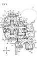
- FIG. 5 is a sectional view taken along line VV of FIG. 2.
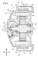
- FIG. 6 is a cross-sectional view taken along line VI-VI of FIG. 2.
- FIG. 1 is a left side view of an electric vehicle 10 according to this embodiment.
- the front-rear direction, the left-right direction, and the up-down direction will be described according to the direction viewed by an occupant seated on the seat 12 of the electric vehicle 10.
- the left and right components of the pair of left and right components may be described with the letter "L” and the right component with the letter "R”.
- the electric vehicle 10 is an electric scooter having a low-floor portion 14, and runs by rotationally driving the rear wheels 16 by the driving force of a motor 20 incorporated in a swing arm 18 that pivotally supports the rear wheels 16.
- the electric vehicle 10 according to the present embodiment is not limited to the electric scooter shown in FIG. 1, and can be applied to various electric saddle type vehicles driven by the motor 20. In the following description, a scooter type electric vehicle 10 will be described.
- the electric vehicle 10 has a vehicle body frame 22 and a synthetic resin vehicle body cover 24 that covers the vehicle body frame 22.
- the vehicle body frame 22 includes a head pipe 26 at a front end, a down pipe 28 extending obliquely downward and rearward from the head pipe 26, a pair of left and right underframe portions 30L and 30R extending rearward from a rear end of the down pipe 28, and an underframe.
- the side frame portions 32L and 32R extend rearward and obliquely upward from the rear ends of the portions 30L and 30R.
- the side frame portions 32L and 32R include rising portions 34L and 34R that extend obliquely upward and rearward from the pair of left and right underframe portions 30L and 30R, and a rear frame 36L that extends rearward from the pair of left and right rising portions 34L and 34R. And 36R.
- the rear ends of the pair of left and right rear frames 36L and 36R are connected by a tail pipe portion 38.
- ⁇ Front forks 40L and 40R are attached to the head pipe 26 in a steerable manner.
- a handlebar 44 is attached to the upper portions of the front forks 40L and 40R via a steering stem 42.
- Front wheels 46 are attached to the lower ends of the front forks 40L and 40R.
- a front fender 48 that covers the front wheel 46 from above is attached to the front forks 40L and 40R.
- a connection support portion 50 including a pivot bracket 50a is provided between the underframe portions 30L and 30R and the side frame portions 32L and 32R.
- the connection support portion 50 supports a pivot shaft 54 extending in the left-right direction (vehicle width direction) of the electric vehicle 10.
- a front end portion (one end portion) of the swing arm 18 is pivotally supported on the pivot shaft 54.
- the swing arm 18 extends from the pivot shaft 54 to the left side of the rear wheel 16 along the front-rear direction of the electric vehicle 10.
- the rear end (the other end) of the swing arm 18 supports the rear wheel 16.
- the swing arm 18 incorporates the motor 20 so that the motor 20 is arranged on the left side of the rear wheel 16. Therefore, the swing arm 18 is configured as a swing type power unit.
- a rear cushion 56 is connected between the rear end of the swing arm 18 and the left rear frame 36L.
- a rear fender 58 that covers the rear wheel 16 from above is attached to the rear frames 36L and 36R. Further, the swing arm 18 is provided with another fender 60 which directly covers the rear wheel 16 from above between the rear fender 58 and the rear wheel 16 and which can swing together with the swing arm 18.
- the rear frames 36L and 36R support the seat 12 on which an occupant is seated from below.
- a battery 62 of the electric vehicle 10 is disposed in a space between the seat 12 and the pivot shaft 54 and between the pair of left and right rising portions 34L and 34R.
- the battery 62 is supported by a pair of left and right rising portions 34L and 34R, rear frames 36L and 36R, and a pipe 64 that connects the rising portions 34L and 34R forward.
- a PCU (power control unit) 66 which is an electronic component supported by the left and right rising portions 34L and 34R, is supported at a position diagonally below and behind the battery 62 in front of the rear wheel 16.
- the PCU 66 is configured to include an inverter and the like, and for example, converts the DC power supplied from the battery 62 into AC power and supplies the converted AC power to the motor 20. Further, when the motor 20 is regenerated, the PCU 66 converts the AC power generated by the motor 20 into DC power and charges the battery 62.
- the locations of the battery 62 and the PCU 66 shown in FIG. 1 are merely examples, and may be located at other locations in the electric vehicle 10. For example, the battery 62 may be arranged in the space between the pair of left and right underframe portions 30L and 30R.
- the vehicle body cover 24 is a cover that covers the vehicle body frame 22 and the like, and includes a front cover 68, a handle cover 70, leg shields 72, floor side covers 74L and 74R, a lower seat cover 76, rear side covers 78L and 78R, and the like.
- the front cover 68 covers the front end portion of the vehicle body frame 22 such as the head pipe 26 from the front.
- the handle cover 70 covers the left and right center portions of the handle 44 above the front cover 68.
- the leg shield 72 is connected to the front cover 68 and covers the head pipe 26 and the down pipe 28 from the rear.
- the under-seat cover 76 covers the space below the seat 12 from the front.
- the pair of left and right floor side covers 74L and 74R are connected to the leg shield 72 and the seat lower cover 76, and cover the pair of left and right underframe portions 30L and 30R from both left and right sides.
- the rear side covers 78L and 78R are connected to the rear edge portion of the lower seat cover 76 and cover the PCU 66 and the like from the left and right sides.
- a main stand 80 is arranged on the side of the swing arm 18.
- the shaft 82 of the main stand 80 is provided below the swing arm 18, and the main stand 80 is arranged so that a part of the main stand 80 is housed in the recess 84 formed by denting the left side portion of the swing arm 18. It is arranged.
- a side stand 86 is provided near the left rising portion 34L.
- the motor 20 is configured as an assembly (unit) in which the stator 90 and the rotor 92 as the drive unit of the motor 20 are incorporated in the motor case 94, and the motor 20 is housed in the swing arm 18.
- Configure a swing-type power unit That is, by mounting the completed motor 20 in which the stator 90 and the rotor 92 are housed and the motor shaft 96 is exposed from the motor case 94 in the swing arm 18, the motor 20 is attached to the swing arm 18. The work is completed.
- the characteristic configuration of the electric vehicle 10 is that the grips 95a and 95b as the grips to be gripped by the operator are provided in the motor case 94, so that even the relatively heavy motor 20 can be attached to the swing arm 18.
- the motor 20 is easily attached and detached.
- the swing arm 18 has a swing arm body 98.
- the swing arm main body 98 is a member having a hollow inside, and has one end 98a extending in the vehicle width direction in the space near the pivot shaft 54 in front of the rear wheel 16 and a connection extending rearward from the left side of the one end 98a. It has a portion 98b, a motor accommodating portion 98c which is connected to the connecting portion 98b and is arranged on the left side of the rear wheel 16, and another end portion 98d which is provided behind the motor accommodating portion 98c.
- the one end portion 98a of the swing arm main body 98 constitutes the front end portion of the swing arm 18, and is pivotally supported by the pivot shaft 54.
- the pivot shaft 54 is supported by the vehicle body frame 22 via the connection support portion 50.
- the connection support portion 50 has a plurality of pivot brackets 50a that extend rearward from the pair of left and right rising portions 34L and 34R and support the pivot shaft 54.
- the connecting portion 98b of the swing arm main body 98 gradually expands from the front to the rear in a side view of FIGS. 1 to 3.
- the motor housing portion 98c and the other end portion 98d of the swing arm body 98 form the rear end portion of the swing arm 18.
- the motor housing portion 98c is formed in a substantially circular shape in the side views of FIGS. 2 and 3, and is formed so as to be recessed inward in the vehicle width direction in the cross-sectional views of FIGS. 5 and 6.
- the rear cushion 56 is connected to the other end 98d of the swing arm body 98.
- the rear portion of the connecting portion 98b and the motor housing portion 98c are open to the left. This opening is opened to a size that can receive the motor 20, and is covered with the swing arm cover 102 from the left side.
- the swing arm cover 102 is attached to the swing arm body 98 with a plurality of bolts 104. 2 to 6 show a state in which the swing arm cover 102 is removed from the swing arm main body 98.
- the motor 20 accommodated in the motor accommodating portion 98c is, for example, a three-phase AC motor, and includes a stator 90, a rotor 92, and a motor case 94 that accommodates the stator 90 and the rotor 92 therein.
- the motor case 94 is an outer box of the motor case 94, and includes a stator support portion 94a as a tubular housing extending in the vehicle width direction and a rotor cover that closes two openings at both ends of the stator support portion 94a in the vehicle width direction. And left and right rotor support portions 94L and 94R.
- the stator 90 has a cylindrical stator core 90a made of laminated steel plates.
- a plurality of slots 90b are formed in the stator core 90a in the circumferential direction of the motor 20 at predetermined angular intervals.
- a coil 90c is wound around the plurality of slots 90b.
- the stator support portion 94a is a stator holder that supports the outer peripheral surface of the stator core 90a, that is, the radially outer surface of the motor 90 of the stator 90 in a fixed state. As a result, the mechanical strength of the stator core 90a made of laminated steel plates is reinforced.
- the stator core 90a is fixed to the stator support portion 94a by shrink fitting, for example.
- a rotor 92 is arranged radially inside the stator 90.
- the rotor 92 has a cylindrical rotor core 92a made of laminated steel plates.
- a plurality of slots 92b are formed in the rotor core 92a in the circumferential direction of the motor 20 at predetermined angular intervals.
- Magnets 92c are arranged in the plurality of slots 92b.
- a motor shaft 96 extends through the center of the rotor core 92a in the vehicle width direction. The motor shaft 96 extends through the openings formed in the central portions of the two rotor support portions 94L and 94R in the vehicle width direction.
- the motor shaft 96 is axially supported by the two rotor support portions 94L and 94R via bearings 106L and 106R provided in the two openings. That is, the rotor 92 is rotatably supported by the two rotor support portions 94L and 94R via the motor shaft 96 and the two bearings 106L and 106R.
- the left end portion 96L of the motor shaft 96 projects outward from the rotor support portion 94L on the left side in the vehicle width direction (to the left).
- a portion where the left end portion 96L of the motor shaft 96 projects is formed as a recess 108 that is recessed inward in the vehicle width direction.
- the recess 108 is covered with a cover member 110 from the left side. Therefore, even if the swing arm cover 102 is removed from the swing arm body 98, the left end portion 96L of the motor shaft 96 is not exposed (see FIGS. 3 to 6).
- a rotation angle detection unit 112 that detects the rotation angles of the rotor 92 and the motor shaft 96 is arranged in the internal space formed by the recess 108 and the cover member 110.
- the rotation angle detector 112 is a resolver, and includes a resolver rotor 112a attached to the left end portion 96L of the motor shaft 96, and a resolver stator 112b fixed to the left rotor support portion 94L so as to face the resolver rotor 112a.
- the right end portion 96R of the motor shaft 96 projects inward (rightward) in the vehicle width direction from the right rotor support portion 94R so as to be directed to the motor housing portion 98c of the swing arm body 98. Therefore, the right rotor support portion 94R and the right side portion of the stator support portion 94a are the portions facing the motor housing portion 98c.
- a speed reducer housing portion 116 that houses the speed reducer 114 is provided.
- the right end portion 96R of the motor shaft 96 is inserted into the reduction gear housing portion 116 and is pivotally supported by a bearing 118 provided in the reduction gear housing portion 116.
- the right end portion 96R side of the motor shaft 96 is splined.
- a motor-side gear 120 for rotating the axle 16a of the rear wheel 16 is inserted in the splined portion.
- a washer 122 for preventing the motor-side gear 120 from coming off is inserted between the motor-side gear 120 and the bearing 118.
- the washer 122 is preferably a low pressure washer with respect to the motor shaft 96 so that the motor 20 can be replaced with respect to the motor housing portion 98c. Since it is the low pressure washer 122, it is easy to assemble.
- the reduction gear accommodating portion 116 is filled with a lubricating oil that lubricates the motor-side gear 120 and the like forming the reduction gear 114. Therefore, an oil seal 121 for preventing leakage of lubricating oil from the reduction gear housing 116 to the motor case 94 is provided between the right rotor support 94R and the motor shaft 96. Further, between the right rotor support portion 94R and the motor housing portion 98c, an O-ring 123 is provided on the rotor support portion 94R side to prevent the leakage of lubricating oil from the reduction gear housing portion 116. There is.
- the motor case 94 more specifically, the two rotor support portions 94L and 94R and the stator support portion 94a are provided with a plurality of boss portions 125 that project outward in the radial direction of the motor 20.
- the plurality of boss portions 125 are formed at predetermined angular intervals in the circumferential direction of the motor 20 so as to extend in the vehicle width direction. As shown in FIGS. 2 to 4, in this embodiment, nine bosses 125 are formed.
- the screw holes 124 (through holes) extending in the vehicle width direction are formed in the plurality of bosses 125. That is, the motor case 94 has nine screw holes 124 formed therein. A plurality of bolts 126 and 128 are screwed into these screw holes 124.
- the short length bolts 126 are screwed into the three screw holes 124.
- the short bolt 126 is used to fix the rotor support portions 94L and 94R and the stator support portion 94a. As shown in FIG. 5, the short bolt 126 is inserted into the screw hole 124 from the left side to tighten and fix the rotor support portion 94L and the stator support portion 94a to the rotor support portion 94R.
- long bolts 128 are screwed into the other six screw holes 124.
- the long bolt 128 is used for fixing the motor case 94 including the two rotor support portions 94L and 94R and the stator support portion 94a to the motor housing portion 98c. That is, the long bolt 128 is inserted into the screw hole 124 from the left side and is screwed into the bolt hole 130 provided in the motor housing portion 98c, whereby the rotor support portion 94L, the stator support portion 94a, and the rotor support portion 94L. 94R is clamped and fixed to the motor housing portion 98c.
- the number and formation position of the screw holes 124 and the types and numbers of the bolts 126 and 128 screwed into the screw holes 124 are arbitrary, and the design may be changed according to the specifications of the swing arm 18 and the motor 20. Of course good things.
- the two gripping portions 95a and 95b extend from the left rotor support portion 94L to the outside in the radial direction of the motor 20. That is, the two grips 95a and 95b are integrally formed with the rotor support 94L.
- the two grips 95a and 95b are arranged substantially symmetrically with the motor shaft 96 interposed therebetween. Further, the outer portions of the two grips 95a and 95b are formed in an arc shape in a side view of FIG. Furthermore, in the rear view of FIG. 4 and the cross-sectional view of FIG. 6, the outer portions of the two grip portions 95a and 95b are chamfered.
- the left rotor support portion 94L is located on the left side (in the vehicle width direction) with respect to the left end portion of the motor housing portion 98c. It is arranged so as to project to the outside). That is, the left rotor support portion 94L and the left end portion of the motor housing portion 98c have different positions along the vehicle width direction. As a result, a gap 127 having a width H is formed between the two grip portions 95a and 95b and the left end portion of the motor housing portion 98c along the axial direction (vehicle width direction) of the motor shaft 96.
- the width H of the gap 127 is set so that the operator's finger can be inserted.
- the position of the left end portion of the motor accommodating portion 98c may be set to the inside of the grip portions 95a and 95b in the vehicle width direction.
- one grip portion 95a extends outward in the radial direction of the motor 20 so as to connect the two boss portions 125 to each other in the upper portion of the left rotor support portion 94L.
- the outer portion of the one grip 95a is formed in a substantially arc shape between the two bosses 125.
- the other grip portion 95b extends outward in the radial direction of the motor 20 so as to connect the two boss portions 125 to each other in the lower portion of the left rotor support portion 94L. Therefore, as described above, the other grip portion 95b is also formed in a substantially arc shape between the two boss portions 125. The front portion of the other grip portion 95b is notched so as to avoid the portion where the bolt 104 is attached to the swing arm body 98.
- the motor case 94 may be configured so that the operator can grip the grip portions 95a and 95b with both hands. Therefore, in this embodiment, the motor case 94 may be provided with at least two grips 95a and 95b. Further, in the present embodiment, a gap 127 having a width H that is large enough for the operator's finger to enter may be formed between the grip portions 95a and 95b and the left end portion of the motor housing portion 98c. If such a gap 127 can be secured, it is also possible to form the grip portions 95a and 95b on the outer peripheral surface of the stator support portion 94a. Furthermore, the two grips 95a and 95b may be connected to at least one boss 125.
- the motor 20 is attached to the motor housing portion 98c of the swing arm body 98.
- the stator 90 and the rotor 92 are housed in the motor case 94, and the right end portion 96R of the motor shaft 96 is projected from the right rotor support portion 94R in an assembled state (unit). Be offered to.
- the short bolts 126 fix the rotor support portions 94L and 94R and the stator support portion 94a in the final fastening state, while the long bolts 128 may be temporarily fastened.
- the worker inserts the right end portion 96R of the motor shaft 96 into the reduction gear housing portion 116 while holding the two grip portions 95a and 95b with both hands.
- the right end portion 96R of the motor shaft 96 is pivotally supported by the bearing 118.
- the right end portion 96R of the motor 20 may be pivotally supported by the bearing 118 with the motor side gear 120 and the washer 122 fitted in the splined portion of the motor shaft 96 on the right end portion 96R side.
- the long bolts 128 are screwed into the screw holes 124 and the bolt holes 130.
- the motor case 94 is fixed to the motor housing portion 98c.
- the motor 20 is housed in the motor housing portion 98c, and the work of attaching the motor 20 to the swing arm 18 is completed.
- the operator when removing the motor 20 from the swing arm 18, first, the operator removes the swing arm cover 102 from the swing arm main body 98 to expose the motor 20. Next, the operator removes the long bolt 128 from the bolt hole 130. Next, the operator inserts his/her hands into the gap 127 and holds the two grips 95a and 95b with both hands, and holds the motor case 94 in front of the operator, that is, to the left (outside in the vehicle width direction). Pull. As a result, the motor shaft 96 is pulled out from the reduction gear housing portion 116, and the motor 20 can be taken out from the motor housing portion 98c.
- the motor 20 is a three-phase AC motor.
- the motor 20 is rotationally driven by supplying AC power from the PCU 66 to the coil 90c via the power supply line 134 as a three-phase line.
- the power supply line 134 is a three-phase wire harness with high rigidity, and is routed inside the swing arm 18 along the internal shape of the swing arm 18. That is, the power supply line 134 extends forward from the motor 20 inside the swing arm 18 and is pulled out forward from one end 98 a of the swing arm main body 98.
- the drawn power supply line 134 is routed above the pivot shaft 54 and is connected to a PCU 66 disposed obliquely below and rearward of the battery 62. Therefore, the PCU 66 and the motor 20 exchange AC power via the power supply line 134.
- a communication line 136 is drawn out from the rotation angle detection unit 112.
- the communication line 136 is a harness whose rigidity is lower than that of the power supply line 134.
- the communication line 136 extends forward from the rotation angle detection unit 112 in the swing arm 18 and extends forward from one end 98a of the swing arm main body 98 so as to crawl on the power supply line 134.
- the pulled-out communication line 136 is routed above the pivot shaft 54 and connected to the PCU 66. Therefore, the PCU 66 and the rotation angle detection unit 112 can transmit and receive the detection result of the rotation angles of the rotor 92 and the motor shaft 96 via the communication line 136.
- the reduction gear accommodating portion 116 that accommodates the reduction gear 114 is provided inside the swing arm body 98 in the vehicle width direction.
- a brake mechanism 150 is provided inside the reduction gear housing 116 in the vehicle width direction and inside the wheel 16 b of the rear wheel 16. Therefore, around the rear wheel 16, the motor 20, the speed reducer 114, and the brake mechanism 150 are sequentially arranged from the left side to the right side in the vehicle width direction.
- a gear case cover 154 is fixed by a bolt 152 to the right side of the motor housing portion 98c of the swing arm body 98.
- An internal space formed by the motor housing portion 98c and the gear case cover 154 is configured as the reduction gear housing portion 116.
- the speed reducer 114 is attached to the motor-side gear 120 mounted on the motor shaft 96, the intermediate shaft 156 disposed behind the motor shaft 96, and extending in the vehicle width direction, and is mounted on the intermediate shaft 156 and meshes with the motor-side gear 120.
- Output gear 162 that is mounted on an intermediate gear 158 as a reduction gear and an axle 16a of a rear wheel 16 arranged behind the intermediate shaft 156 and meshes with a gear portion 160 formed on the left side of the intermediate shaft 156 in the vehicle width direction.
- the right end of the intermediate shaft 156 is pivotally supported by a bearing 164R arranged on the gear case cover 154.
- the left end portion of the intermediate shaft 156 is pivotally supported by a bearing 164L arranged on the right side of the motor housing portion 98c.
- the left end portion of the axle 16a is pivotally supported by a bearing 166L arranged on the right side of the motor housing portion 98c.
- the right end of the axle 16a penetrates the gear case cover 154, is exposed to the outside, and is connected to the wheel 16b of the rear wheel 16.
- the right end side of the axle 16a is pivotally supported by a bearing 166R arranged on the gear case cover 154.
- the speed reducer 114 reduces the rotational speed of the motor shaft 96 by the intermediate gear 158 to rotationally drive the axle 16a and the rear wheel 16.
- the brake mechanism 150 is a drum brake, and includes a drum 150a provided inside the wheel 16b, two shoes 150b arranged on both sides of the axle 16a, and a lining arranged on the drum 150a side of the shoe 150b. 150c and.
- the drum brake is well known, its detailed description is omitted.
- the electric vehicle 10 includes a vehicle body frame 22, a pivot shaft 54 provided on the vehicle body frame 22, a front end portion (one end portion) pivotally supported by the pivot shaft 54, and a rear end portion (the other end portion).
- a swing arm 18 that supports the rear wheel 16
- a motor 20 that is disposed on the swing arm 18 and that drives the rear wheel 16.
- the electric vehicle 10 further includes a motor housing portion 98c that is provided on the swing arm 18 and that houses the motor 20.
- the motor 20 includes a stator 90, a rotor 92, and a motor case 94 that accommodates the stator 90 in a fixed state and that rotatably accommodates the rotor 92 therein.
- the motor case 94 has grip portions 95a and 95b extending outward in the radial direction of the motor 20.
- a gap 127 is formed between the grip portions 95a and 95b and the motor housing portion 98c along the axial direction of the motor shaft 96 (left-right direction, vehicle width direction).
- the gap 127 in the axial direction can secure a space (width H) that is small enough to receive a finger of an operator when the motor 20 is assembled.
- the size of the motor housing portion 98c in the radial direction can be reduced as compared with the case where a gap is secured in the radial direction of the motor 20.
- the motor case 94 has rotor support portions 94L and 94R that rotatably support the rotor 92, and a stator support portion 94a that supports a radial side surface of the motor 90 in the stator 90.
- the grip portions 95a and 95b are integrally formed with the left rotor support portion 94L.
- the rotor support portions 94L and 94R are provided with a plurality of boss portions 125 that project outward in the radial direction of the motor 20.
- the plurality of bosses 125 are formed with screw holes 124 through which the bolts 126 and 128 are inserted.
- the grips 95a and 95b are connected to at least one boss 125. Thereby, the mechanical strength of the grip portions 95a and 95b can be ensured.
- the grip portions 95a and 95b are formed so as to connect the two boss portions 125, the mechanical strength of the grip portions 95a and 95b can be further secured.
- the motor case 94 is provided with at least two grips 95a and 95b, and the two grips 95a and 95b are arranged substantially symmetrically with the motor shaft 96 interposed therebetween. This allows the operator to easily grip the grip portions 95a and 95b with both hands. As a result, the work of attaching and detaching the motor 20 to and from the motor housing portion 98c can be performed more easily and efficiently.
- the radial width (size) of the grips 95a and 95b as the handles can be maximized.
Landscapes
- Engineering & Computer Science (AREA)
- Mechanical Engineering (AREA)
- Chemical & Material Sciences (AREA)
- Combustion & Propulsion (AREA)
- Transportation (AREA)
- Axle Suspensions And Sidecars For Cycles (AREA)
- Motor Or Generator Frames (AREA)
- Arrangement Or Mounting Of Propulsion Units For Vehicles (AREA)
Abstract
電動車両(10)は、スイングアーム(18)に設けられ、モータ(20)を収容するモータ収容部(98c)を備える。この場合、モータ(20)は、ステータ(90)と、ロータ(92)と、ステータ(90)を固定状態で内部に収容し、一方で、ロータ(92)を回転自在に内部に収容するモータケース(94)とを有する。モータケース(94)は、モータ(20)の径方向外側に延びる把持部(95a、95b)を有する。
Description
本発明は、ピボット軸に軸支されたスイングアームにモータが配置された電動車両に関する。
特開2012-171548号公報には、車体フレームと、車体フレームに設けられたピボット軸と、一端部がピボット軸に軸支されるスイングアームと、スイングアームの他端部に支持される後輪と、スイングアームの内部に配置され、後輪を駆動するモータとを備える電動車両が開示されている。この場合、スイングアームは、後輪を軸支するスイングアーム主体と、スイングアーム主体を車幅方向外側から覆うスイングアームカバーとから構成される。モータは、スイングアーム主体とスイングアームカバーとの間の内部空間に収容される。
モータは、比較的重量があると共に、円筒形状である。そのため、モータをスイングアームに挿入する際、作業者は、モータを持ちにくいため、作業負担が大きくなる。これにより、スイングアームに対してモータの位置を精度よく合わせるための組立作業に時間がかかる。
そこで、本発明は、スイングアームに対するモータの取付作業性を向上させることで、組立時間の短縮化を実現可能な電動車両を提供することを目的とする。
本発明の態様は、車体フレームと、前記車体フレームに設けられたピボット軸と、一端部が前記ピボット軸に軸支され、他端部が後輪を支持するスイングアームと、前記スイングアームに配置され、前記後輪を駆動するモータとを備える電動車両において、前記スイングアームに設けられ、前記モータを収容するモータ収容部をさらに備え、前記モータは、ステータと、ロータと、前記ステータを固定状態で内部に収容し、一方で、前記ロータを回転自在に内部に収容するモータケースとを有し、前記モータケースは、前記モータの径方向外側に延びる把持部を有する。
本発明によれば、持ち手としての把持部をモータケースに設けることで、作業者は、モータをスイングアームに挿入する際、モータを持ちやすくなる。この結果、スイングアームに対するモータの取付作業性が向上する。これにより、組立時間の短縮化を実現することができる。
以下、本発明に係る電動車両の好適な実施形態について、添付の図面を参照しながら説明する。
[1.本実施形態に係る電動車両10の概略構成]
図1は、本実施形態に係る電動車両10の左側面図である。なお、以下の説明では、電動車両10のシート12に着座した乗員の見た方向に従って、前後、左右及び上下の方向を説明する。また、電動車両10において、左右一対に配設される構成要素については、左側の構成要素については「L」、右側の構成要素については「R」の文字を付けて説明する場合がある。
図1は、本実施形態に係る電動車両10の左側面図である。なお、以下の説明では、電動車両10のシート12に着座した乗員の見た方向に従って、前後、左右及び上下の方向を説明する。また、電動車両10において、左右一対に配設される構成要素については、左側の構成要素については「L」、右側の構成要素については「R」の文字を付けて説明する場合がある。
電動車両10は、低床のフロア部14を有する電動スクータであり、後輪16を軸支するスイングアーム18に内蔵されたモータ20の駆動力で後輪16を回転駆動させることにより走行する。なお、本実施形態に係る電動車両10は、図1の電動スクータに限定されることはなく、モータ20によって駆動する各種の電動の鞍乗型車両に適用可能である。以下の説明では、スクータ型の電動車両10について説明する。
電動車両10は、車体フレーム22と、車体フレーム22を覆う合成樹脂製の車体カバー24とを有する。車体フレーム22は、前端部のヘッドパイプ26と、ヘッドパイプ26から後ろ斜め下方に延びるダウンパイプ28と、ダウンパイプ28の後端から後方に延びる左右一対のアンダーフレーム部30L、30Rと、アンダーフレーム部30L、30Rの後端から後ろ斜め上方に延びるサイドフレーム部32L、32Rとから構成される。サイドフレーム部32L、32Rは、左右一対のアンダーフレーム部30L、30Rから後ろ斜め上方に延びる立ち上げ部34L、34Rと、左右一対の立ち上げ部34L、34Rから後方に延出するリヤフレーム36L、36Rとから構成される。左右一対のリヤフレーム36L、36Rの後端は、テールパイプ部38で連結されている。
ヘッドパイプ26には、フロントフォーク40L、40Rが操舵自在に取り付けられている。フロントフォーク40L、40Rの上部には、ステアリングステム42を介して、ハンドル44が取り付けられている。フロントフォーク40L、40Rの下端には、前輪46が取り付けられている。フロントフォーク40L、40Rには、前輪46を上方から覆うフロントフェンダ48が取り付けられている。
アンダーフレーム部30L、30Rとサイドフレーム部32L、32Rとの間には、ピボットブラケット50aを含む連結支持部50が設けられている。連結支持部50は、電動車両10の左右方向(車幅方向)に延びるピボット軸54を支持する。ピボット軸54には、スイングアーム18の前端部(一端部)が軸支されている。スイングアーム18は、ピボット軸54から電動車両10の前後方向に沿って、後輪16の左側方に延びている。スイングアーム18の後端部(他端部)は、後輪16を支持する。
スイングアーム18は、後輪16の左側方にモータ20が配置されるように、該モータ20を内蔵する。従って、スイングアーム18は、スイング式のパワーユニットとして構成される。スイングアーム18の後端部と左側のリヤフレーム36Lとの間には、リヤクッション56が連結されている。また、リヤフレーム36L、36Rには、後輪16を上方から覆うリヤフェンダ58が取り付けられている。さらに、スイングアーム18には、リヤフェンダ58と後輪16との間で後輪16を上方から直接覆い、且つ、スイングアーム18と共に揺動可能な他のフェンダ60が取り付けられている。
リヤフレーム36L、36Rは、乗員が着座するシート12を下側から支持する。シート12とピボット軸54との間で、左右一対の立ち上げ部34L、34Rの間の空間には、電動車両10のバッテリ62が配置されている。バッテリ62は、左右一対の立ち上げ部34L、34R及びリヤフレーム36L、36Rと、立ち上げ部34L、34Rを前方で連結するパイプ64とによって支持されている。
後輪16の前方にあって、バッテリ62の後ろ斜め下方の箇所には、左右の立ち上げ部34L、34Rによって支持される電子部品としてのPCU(パワーコントロールユニット)66が支持されている。PCU66は、インバータ等を含み構成され、例えば、バッテリ62から供給される直流電力を交流電力に変換し、変換後の交流電力をモータ20に供給する。また、PCU66は、モータ20の回生時には、モータ20が発電した交流電力を直流電力に変換し、バッテリ62に充電する。なお、図1に示すバッテリ62及びPCU66の配置箇所は、一例であって、電動車両10内の他の箇所に配置してもよい。例えば、左右一対のアンダーフレーム部30L、30Rの間の空間にバッテリ62を配置してもよい。
車体カバー24は、車体フレーム22等を覆うカバーであって、フロントカバー68、ハンドルカバー70、レッグシールド72、フロアサイドカバー74L、74R、シート下カバー76及びリヤサイドカバー78L、78R等を有する。フロントカバー68は、ヘッドパイプ26等の車体フレーム22の前端部を前方から覆う。ハンドルカバー70は、フロントカバー68の上方で、ハンドル44の左右中央部を覆う。レッグシールド72は、フロントカバー68に接続され、ヘッドパイプ26及びダウンパイプ28を後方から覆う。シート下カバー76は、シート12下方の空間を前方から覆う。
左右一対のフロアサイドカバー74L、74Rは、レッグシールド72及びシート下カバー76に連結され、左右一対のアンダーフレーム部30L、30Rを左右両側から覆う。リヤサイドカバー78L、78Rは、シート下カバー76の後縁部に接続され、PCU66等を左右両側から覆う。
スイングアーム18の側方には、メインスタンド80が配設されている。この場合、スイングアーム18の下方にメインスタンド80の軸82が設けられ、スイングアーム18の左側部を凹ませた凹部84にメインスタンド80の一部が収容されるように、該メインスタンド80が配設される。また、左側の立ち上げ部34Lの近傍には、サイドスタンド86が配設されている。
[2.本実施形態の特徴的な構成]
次に、本実施形態に係る電動車両10の特徴的な構成について、図1~図6を参照しながら説明する。
次に、本実施形態に係る電動車両10の特徴的な構成について、図1~図6を参照しながら説明する。
電動車両10では、モータ20の駆動部としてのステータ90及びロータ92をモータケース94に組み込んだ組立体(ユニット)として該モータ20が構成され、モータ20をスイングアーム18内に収容することで、スイング式のパワーユニットを構成する。すなわち、ステータ90及びロータ92が収容され、且つ、モータケース94からモータ軸96が露出している完成品のモータ20を、スイングアーム18内に収容するだけで、スイングアーム18に対するモータ20の取付作業が完了する。
電動車両10の特徴的な構成とは、作業者が把持する持ち手としての把持部95a、95bをモータケース94に設けることで、比較的重量のあるモータ20であっても、スイングアーム18に対するモータ20の取り付け及び取り外しを容易にしたものである。
ここで、モータ20が収容されているスイングアーム18の構成について、より詳しく説明する。
スイングアーム18は、スイングアーム本体98を有する。スイングアーム本体98は、内部が空洞の部材であって、後輪16の前方におけるピボット軸54近傍の空間で車幅方向に延びる一端部98aと、一端部98aの左側から後方に延出する連結部98bと、連結部98bに連設され、後輪16の左側方に配置されたモータ収容部98cと、モータ収容部98cの後方に設けられた他端部98dとを有する。
スイングアーム本体98の一端部98aは、スイングアーム18の前端部を構成し、ピボット軸54に軸支されている。前述のように、ピボット軸54は、連結支持部50を介して車体フレーム22に支持されている。連結支持部50は、左右一対の立ち上げ部34L、34R側から後方に延びてピボット軸54を支持する複数のピボットブラケット50aを有する。
スイングアーム本体98の連結部98bは、図1~図3の側面視で、前方から後方に向って徐々に拡開している。スイングアーム本体98のモータ収容部98c及び他端部98dは、スイングアーム18の後端部を構成する。モータ収容部98cは、図2及び図3の側面視で略円形状に形成され、且つ、図5及び図6の断面視で車幅方向内側に凹むように形成されている。スイングアーム本体98の他端部98dには、リヤクッション56が連結されている。
スイングアーム本体98において、連結部98bの後部及びモータ収容部98cは、左側方に開口している。この開口部分は、モータ20を受容可能な大きさに開口され、スイングアームカバー102で左方から覆われている。スイングアームカバー102は、複数のボルト104によってスイングアーム本体98に取り付けられる。なお、図2~図6は、スイングアーム本体98からスイングアームカバー102を取り外した状態を図示している。
モータ収容部98cに収容されるモータ20は、例えば、三相の交流モータであって、ステータ90と、ロータ92と、ステータ90及びロータ92を内部に収容するモータケース94とを有する。モータケース94は、該モータケース94の外箱であって、車幅方向に延びる筒状のハウジングとしてのステータ支持部94aと、ステータ支持部94aの車幅方向両端の2つの開口を塞ぐロータカバーとしての左右のロータ支持部94L、94Rとを有する。
ステータ90は、積層鋼板からなる円筒状のステータコア90aを有する。ステータコア90aには、モータ20の周方向に複数のスロット90bが所定角度間隔で形成されている。複数のスロット90bにはコイル90cが巻回されている。ステータ支持部94aは、ステータコア90aの外周面、すなわち、ステータ90におけるモータ20の径方向の外側面を固定状態で支持するステータホルダである。これにより、積層鋼板から構成されるステータコア90aの機械的強度が補強される。なお、ステータコア90aは、例えば、焼き嵌めによってステータ支持部94aに固定される。
ステータ90の径方向内側には、ロータ92が配置されている。ロータ92は、積層鋼板からなる円筒状のロータコア92aを有する。ロータコア92aには、モータ20の周方向に複数のスロット92bが所定角度間隔で形成されている。複数のスロット92bには磁石92cが配置されている。ロータコア92aの中心には、モータ軸96が車幅方向に貫通している。モータ軸96は、2つのロータ支持部94L、94Rの中心部に形成された開口を貫通して車幅方向に延在している。モータ軸96は、2つの開口に設けられた軸受106L、106Rを介して2つのロータ支持部94L、94Rに軸支されている。つまり、ロータ92は、モータ軸96及び2つの軸受106L、106Rを介して、回転自在に2つのロータ支持部94L、94Rに軸支されている。
モータ軸96の左端部96Lは、左側のロータ支持部94Lから車幅方向外側(左方向)に突出している。左側のロータ支持部94Lにおいて、モータ軸96の左端部96Lが突出する箇所は、車幅方向内側に凹む凹部108として形成されている。凹部108は、カバー部材110によって左方から覆われている。従って、スイングアーム本体98からスイングアームカバー102を取り外しても、モータ軸96の左端部96Lが露出することはない(図3~図6参照)。
凹部108とカバー部材110とで形成される内部空間には、ロータ92及びモータ軸96の回転角度を検出する回転角度検出部112が配設されている。回転角度検出部112は、レゾルバであって、モータ軸96の左端部96Lに取り付けられたレゾルバロータ112aと、レゾルバロータ112aに対向するように左側のロータ支持部94Lに固定されたレゾルバステータ112bとを有する。なお、レゾルバは周知であるため、その詳細な説明は省略する。
一方、モータ軸96の右端部96Rは、スイングアーム本体98のモータ収容部98cに指向するように、右側のロータ支持部94Rから車幅方向内側(右方向)に突出している。従って、右側のロータ支持部94Rとステータ支持部94aの右側部分とが、モータ収容部98cとの対向部分となる。スイングアーム本体98のモータ収容部98cの右側には、減速機114を収容する減速機収容部116が設けられている。
モータ軸96の右端部96Rは、減速機収容部116に挿入され、該減速機収容部116に設けられた軸受118によって軸支されている。また、モータ軸96の右端部96R側には、スプライン加工が施されている。スプライン加工が施された部分には、後輪16の車軸16aを回転させるためのモータ側ギヤ120が挿入されている。さらに、モータ側ギヤ120と軸受118との間には、モータ側ギヤ120の抜け止めを防止するためのワッシャ122が介挿されている。なお、モータ収容部98cに対してモータ20を交換可能とするため、ワッシャ122は、モータ軸96に対して低圧入のワッシャであることが望ましい。低圧入のワッシャ122であるため、組み付けが容易である。
また、減速機収容部116には、減速機114を構成するモータ側ギヤ120等を潤滑する潤滑油が充填されている。そのため、右側のロータ支持部94Rとモータ軸96との間には、減速機収容部116からモータケース94への潤滑油の漏洩を阻止するためのオイルシール121が設けられている。また、右側のロータ支持部94Rとモータ収容部98cとの間で、該ロータ支持部94R側には、減速機収容部116からの潤滑油の漏洩を阻止するためのOリング123が設けられている。
そして、モータケース94、より詳しくは、2つのロータ支持部94L、94R及びステータ支持部94aには、モータ20の径方向外側に突出するボス部125が複数設けられている。複数のボス部125は、車幅方向に延びるように、モータ20の周方向に所定角度間隔で形成されている。図2~図4に示すように、本実施形態では、ボス部125が9箇所形成されている。
複数のボス部125には、車幅方向に延びるネジ孔124(貫通孔)が形成されている。すなわち、モータケース94には、ネジ孔124が9箇所形成されている。これらのネジ孔124には、複数のボルト126、128が螺合する。
このうち、3箇所のネジ孔124には、長さの短いボルト126が螺合している。短いボルト126は、ロータ支持部94L、94Rとステータ支持部94aとの固定に用いられる。図5に示すように、短いボルト126は、ネジ孔124に対して左方から挿入されることで、ロータ支持部94L及びステータ支持部94aをロータ支持部94Rに締付固定する。
一方、他の6箇所のネジ孔124には、長いボルト128が螺合している。長いボルト128は、2つのロータ支持部94L、94R及びステータ支持部94aを含むモータケース94のモータ収容部98cへの固定に用いられる。すなわち、長いボルト128は、ネジ孔124に対して左方から挿入され、モータ収容部98cに設けられたボルト穴130に螺合することで、ロータ支持部94L、ステータ支持部94a及びロータ支持部94Rをモータ収容部98cに締付固定する。
なお、ネジ孔124の個数及び形成位置や、各ネジ孔124に螺合するボルト126、128の種類及び個数は任意であり、スイングアーム18及びモータ20の仕様等に応じて設計変更してもよいことは勿論である。
そして、図2、図4及び図6に示すように、モータケース94では、2つの把持部95a、95bが左側のロータ支持部94Lからモータ20の径方向外側に延びている。すなわち、2つの把持部95a、95bは、ロータ支持部94Lと一体に構成されている。また、2つの把持部95a、95bは、モータ軸96を挟んで略対称に配置されている。さらに、2つの把持部95a、95bの外側部分は、図2の側面視で、円弧状に形成されている。さらにまた、図4の背面視及び図6の断面視で、2つの把持部95a、95bの外側部分は、面取りされている。
しかも、図4~図6に示すように、モータケース94がモータ収容部98cに収容されている場合、左側のロータ支持部94Lは、モータ収容部98cの左端部よりも、左側(車幅方向外側)に突出するように配置されている。すなわち、左側のロータ支持部94Lと、モータ収容部98cの左端部とでは、車幅方向に沿った位置が異なる。この結果、2つの把持部95a、95bとモータ収容部98cの左端部との間には、モータ軸96の軸方向(車幅方向)に沿って、幅Hの隙間127が形成される。
なお、隙間127の幅Hは、作業者の指が入る程度に設定されている。このような隙間127を形成するため、モータ収容部98cの左端部の位置を、把持部95a、95bよりも車幅方向内側に設定すればよい。
この場合、一方の把持部95aは、左側のロータ支持部94Lの上側部分において、2つのボス部125同士を連結するように、モータ20の径方向外側に延びている。前述のように、一方の把持部95aの外側部分は、2つのボス部125の間で略円弧状に形成されている。
また、他方の把持部95bは、左側のロータ支持部94Lの下側部分において、2つのボス部125同士を連結するように、モータ20の径方向外側に延びている。そのため、前述のように、他方の把持部95bも、2つのボス部125の間で略円弧状に形成されている。他方の把持部95bの前方部分は、スイングアーム本体98におけるボルト104の取付部分を避けるように、切り欠かれている。
なお、本実施形態では、作業者が両手で把持部95a、95bを把持可能にモータケース94が構成されていればよい。そのため、本実施形態では、モータケース94に少なくとも2つの把持部95a、95bが設けられていればよい。また、本実施形態では、作業者の指が入る程度の幅Hの隙間127が把持部95a、95bとモータ収容部98cの左端部との間に形成されていればよい。このような隙間127を確保できるのであれば、ステータ支持部94aの外周面に把持部95a、95bを形成することも可能である。さらに、2つの把持部95a、95bは、少なくとも1つのボス部125と連結されていればよい。
そして、電動車両10を製造する際、スイングアーム本体98のモータ収容部98cにモータ20を取り付ける。モータ20は、ステータ90及びロータ92をモータケース94に収容し、モータ軸96の右端部96Rを右側のロータ支持部94Rから突出させた組立体(ユニット)の状態で、電動車両10の製造工程に供される。その際、長さの短いボルト126は、本留めの状態でロータ支持部94L、94Rとステータ支持部94aとを固定し、一方で、長いボルト128は、仮留めの状態にしておけばよい。
この場合、先ず、作業者は、2つの把持部95a、95bを両手で把持した状態で、モータ軸96の右端部96Rを減速機収容部116に挿入する。これにより、モータ軸96の右端部96Rは、軸受118に軸支される。その際、モータ軸96の右端部96R側のスプライン加工された部分にモータ側ギヤ120とワッシャ122とを嵌め込んだ状態で、モータ20の右端部96Rを軸受118に軸支させればよい。次に、長いボルト128が仮留めされている6箇所のネジ孔124とモータ収容部98c側の6箇所のボルト穴130とを位置決めした後に、長いボルト128をネジ孔124及びボルト穴130に螺合させることで、モータケース94をモータ収容部98cに固定する。これにより、モータ収容部98cにモータ20が収容され、スイングアーム18に対するモータ20の取付作業が完了する。
一方、スイングアーム18からモータ20を取り外す場合、先ず、作業者は、スイングアーム本体98からスイングアームカバー102を取り外して、モータ20を露出させる。次に、作業者は、長いボルト128をボルト穴130から取り外す。次に、作業者は、隙間127に両手を差し込み、2つの把持部95a、95bを両手で把持した状態で、作業者の手前側、すなわち、左方向(車幅方向外側)にモータケース94を引く。これにより、モータ軸96が減速機収容部116から引き抜かれ、モータ収容部98cからモータ20を取り出すことができる。
[3.電動車両10のその他の構成]
次に、電動車両10について、上述した構成要素以外の構成について、図1~図6を参照しながら、簡単に説明する。
次に、電動車両10について、上述した構成要素以外の構成について、図1~図6を参照しながら、簡単に説明する。
前述のように、モータ20は、三相の交流モータである。モータ20は、PCU66から三相線としての給電線134を介してコイル90cに交流電力を供給することで回転駆動する。給電線134は、剛性の高い三相線のハーネスであり、スイングアーム18の内部形状に沿って、スイングアーム18内を引き回されている。すなわち、給電線134は、スイングアーム18の内部でモータ20から前方に延び、スイングアーム本体98の一端部98aから前方に引き出されている。引き出された給電線134は、ピボット軸54の上方に引き回され、バッテリ62の後ろ斜め下方に配置されたPCU66に接続されている。従って、PCU66とモータ20とは、給電線134を介して交流電力の授受を行う。
一方、回転角度検出部112からは通信線136が引き出されている。通信線136は、給電線134よりも剛性の低いハーネスである。通信線136は、給電線134に這わせるように、スイングアーム18内で回転角度検出部112から前方に延び、スイングアーム本体98の一端部98aから前方に引き出されている。引き出された通信線136は、ピボット軸54の上方に引き回され、PCU66に接続される。従って、PCU66と回転角度検出部112とは、通信線136を介して、ロータ92及びモータ軸96の回転角度の検出結果の送受信が可能である。
前述のように、スイングアーム本体98の車幅方向内側には、減速機114を収容する減速機収容部116が設けられている。また、減速機収容部116よりも車幅方向内側であって、後輪16のホイール16bの内側には、ブレーキ機構150が設けられている。従って、後輪16の周辺では、車幅方向の左側から右側に向かって、モータ20、減速機114及びブレーキ機構150が順に配置されている。
また、スイングアーム本体98のモータ収容部98cの右側には、ボルト152によってギヤケースカバー154が固定されている。モータ収容部98cとギヤケースカバー154とによって形成される内部空間が減速機収容部116として構成される。
減速機114は、モータ軸96に装着されたモータ側ギヤ120と、モータ軸96の後方に配置され、車幅方向に延びる中間軸156と、中間軸156に装着され、モータ側ギヤ120に噛合するリダクションギヤとしての中間ギヤ158と、中間軸156の後方に配置された後輪16の車軸16aに装着され、中間軸156の車幅方向左側に形成されたギヤ部160に噛合する出力ギヤ162とを有する。
中間軸156の右端部は、ギヤケースカバー154に配置された軸受164Rに軸支されている。中間軸156の左端部は、モータ収容部98cの右側に配置された軸受164Lに軸支されている。車軸16aの左端部は、モータ収容部98cの右側に配置された軸受166Lに軸支されている。車軸16aの右端部は、ギヤケースカバー154を貫通して外部に露出し、後輪16のホイール16bに連結されている。車軸16aの右端部側は、ギヤケースカバー154に配置された軸受166Rに軸支されている。
従って、モータ20が駆動してモータ軸96が回転した際、モータ20の駆動力がモータ側ギヤ120、中間ギヤ158、中間軸156、ギヤ部160及び出力ギヤ162を介して車軸16aに伝達され、車軸16aに連結された後輪16を回転させることができる。この場合、減速機114は、モータ軸96の回転速度を中間ギヤ158によって減速させ、車軸16a及び後輪16を回転駆動させる。
ブレーキ機構150は、ドラムブレーキであって、ホイール16bの内側に設けられたドラム150aと、車軸16aを挟んで両側に配置された2つのシュー150bと、シュー150bのドラム150a側に配置されたライニング150cとを有する。この場合、2つのシュー150bの間に介挿された不図示のバネ部材の引張力に抗して、2つのシュー150bを互いに離間させると、2つのシュー150bのライニング150cがドラム150aをそれぞれ押圧するので、ドラム150aが装着されたホイール16b(後輪16)の回転を制動させることができる。なお、ドラムブレーキは周知であるため、その詳細な説明は省略する。
[4.本実施形態の効果]
以上説明した本実施形態に係る電動車両10の効果について説明する。
以上説明した本実施形態に係る電動車両10の効果について説明する。
本実施形態に係る電動車両10は、車体フレーム22と、車体フレーム22に設けられたピボット軸54と、前端部(一端部)がピボット軸54に軸支され、後端部(他端部)が後輪16を支持するスイングアーム18と、スイングアーム18に配置され、後輪16を駆動するモータ20とを備える。
そして、電動車両10は、スイングアーム18に設けられ、モータ20を収容するモータ収容部98cをさらに備える。モータ20は、ステータ90と、ロータ92と、ステータ90を固定状態で内部に収容し、一方で、ロータ92を回転自在に内部に収容するモータケース94とを有する。モータケース94は、モータ20の径方向外側に延びる把持部95a、95bを有する。
このように、持ち手としての把持部95a、95bをモータケース94に設けることで、作業者は、モータ20をスイングアーム18に挿入する際、モータ20を持ちやすくなる。この結果、スイングアーム18に対するモータ20の取付作業性が向上する。これにより、組立時間の短縮化を実現することができる。
また、把持部95a、95bとモータ収容部98cとの間には、モータ軸96の軸方向(左右方向、車幅方向)に沿った隙間127が形成されている。このように、軸方向に隙間127があることで、モータ20を組み付けたときに作業者の指が入る程度のスペース(幅H)を確保することができる。また、モータ20の径方向に隙間を確保する場合と比較して、モータ収容部98cの径方向のサイズを小さくすることができる。
さらに、モータケース94は、ロータ92を回転自在に支持するロータ支持部94L、94Rと、ステータ90におけるモータ20の径方向の側面を支持するステータ支持部94aとを有する。この場合、把持部95a、95bは、左側のロータ支持部94Lと一体に構成されている。これにより、モータ20を含めた電動車両10の部品点数を削減することができる。
さらにまた、ロータ支持部94L、94Rには、モータ20の径方向外側に突出するボス部125が複数設けられている。複数のボス部125には、ボルト126、128を挿通させるネジ孔124が形成されている。把持部95a、95bは、少なくとも1つのボス部125と連結している。これにより、把持部95a、95bの機械的強度を確保することができる。
この場合、2つのボス部125同士を連結するように把持部95a、95bを形成すると、把持部95a、95bの機械的強度を一層確保することができる。
また、モータケース94には、少なくとも2つの把持部95a、95bが設けられ、2つの把持部95a、95bは、モータ軸96を挟んで略対称に配置されている。これにより、作業者は、両手で把持部95a、95bを容易に把持することができる。この結果、モータ収容部98cに対するモータ20の取り付け作業及び取り外し作業を一層容易に且つ効率よく行うことができる。
さらに、把持部95a、95bの外側部分を、側面視で、円弧状とすれば、持ち手としての把持部95a、95bの径方向の幅(サイズ)を最大化することができる。
さらにまた、把持部95a、95bの外側部分を面取りすれば、角がないため、作業者は、該把持部95a、95bを持ち易くなる。
以上、本発明について好適な実施形態を用いて説明したが、本発明の技術的範囲は、上記の実施形態の記載範囲に限定されることはない。上記の実施形態に、多様な変更又は改良を加えることが可能であることは、当業者に明らかである。そのような変更又は改良を加えた形態も、本発明の技術的範囲に含まれ得ることが、請求の範囲の記載から明らかである。また、請求の範囲に記載された括弧書きの符号は、本発明の理解の容易化のために添付図面中の符号に倣って付したものであり、本発明がその符号をつけた要素に限定されて解釈されるものではない。
Claims (8)
- 車体フレーム(22)と、前記車体フレーム(22)に設けられたピボット軸(54)と、一端部が前記ピボット軸(54)に軸支され、他端部が後輪(16)を支持するスイングアーム(18)と、前記スイングアーム(18)に配置され、前記後輪(16)を駆動するモータ(20)とを備える電動車両(10)において、
前記スイングアーム(18)に設けられ、前記モータ(20)を収容するモータ収容部(98c)をさらに備え、
前記モータ(20)は、ステータ(90)と、ロータ(92)と、前記ステータ(90)を固定状態で内部に収容し、一方で、前記ロータ(92)を回転自在に内部に収容するモータケース(94)とを有し、
前記モータケース(94)は、前記モータ(20)の径方向外側に延びる把持部(95a、95b)を有する、電動車両(10)。 - 請求項1記載の電動車両(10)において、
前記把持部(95a、95b)と前記モータ収容部(98c)との間には、モータ軸(96)の軸方向に沿った隙間(127)が形成される、電動車両(10)。 - 請求項1又は2記載の電動車両(10)において、
前記モータケース(94)は、前記ロータ(92)を回転自在に支持するロータ支持部(94L、94R)と、前記ステータ(90)における前記モータ(20)の径方向の側面を支持するステータ支持部(94a)とを有し、
前記把持部(95a、95b)は、前記ロータ支持部(94L)と一体に構成されている、電動車両(10)。 - 請求項3記載の電動車両(10)において、
前記ロータ支持部(94L、94R)には、該モータ(20)の径方向外側に突出するボス部(125)が複数設けられ、
複数の前記ボス部(125)には、ボルト(126、128)を挿通させる貫通孔(124)が形成され、
前記把持部(95a、95b)は、少なくとも1つの前記ボス部(125)と連結している、電動車両(10)。 - 請求項4記載の電動車両(10)において、
前記把持部(95a、95b)は、2つの前記ボス部(125)同士を連結するように形成されている、電動車両(10)。 - 請求項1~5のいずれか1項に記載の電動車両(10)において、
前記モータケース(94)には、少なくとも2つの前記把持部(95a、95b)が設けられ、
2つの前記把持部(95a、95b)は、モータ軸(96)を挟んで対称に配置されている、電動車両(10)。 - 請求項1~6のいずれか1項に記載の電動車両(10)において、
前記把持部(95a、95b)の外側部分は、側面視で、円弧状である、電動車両(10)。 - 請求項1~7のいずれか1項に記載の電動車両(10)において、
前記把持部(95a、95b)の外側部分は、面取りされている、電動車両(10)。
Priority Applications (2)
| Application Number | Priority Date | Filing Date | Title |
|---|---|---|---|
| CN201980091369.9A CN113423633B (zh) | 2019-02-05 | 2019-11-12 | 电动车辆 |
| JP2020570375A JP7076587B2 (ja) | 2019-02-05 | 2019-11-12 | 電動車両 |
Applications Claiming Priority (2)
| Application Number | Priority Date | Filing Date | Title |
|---|---|---|---|
| JP2019-018594 | 2019-02-05 | ||
| JP2019018594 | 2019-02-05 |
Publications (1)
| Publication Number | Publication Date |
|---|---|
| WO2020161980A1 true WO2020161980A1 (ja) | 2020-08-13 |
Family
ID=71947535
Family Applications (1)
| Application Number | Title | Priority Date | Filing Date |
|---|---|---|---|
| PCT/JP2019/044290 Ceased WO2020161980A1 (ja) | 2019-02-05 | 2019-11-12 | 電動車両 |
Country Status (3)
| Country | Link |
|---|---|
| JP (1) | JP7076587B2 (ja) |
| CN (1) | CN113423633B (ja) |
| WO (1) | WO2020161980A1 (ja) |
Citations (2)
| Publication number | Priority date | Publication date | Assignee | Title |
|---|---|---|---|---|
| JPH05105177A (ja) * | 1991-10-14 | 1993-04-27 | Yamaha Motor Co Ltd | 電動二輪車の動力ユニツト |
| JP2011160506A (ja) * | 2010-01-29 | 2011-08-18 | Sanyo Electric Co Ltd | モールドモータ及びこれを搭載した電動車両 |
Family Cites Families (8)
| Publication number | Priority date | Publication date | Assignee | Title |
|---|---|---|---|---|
| JP2005194930A (ja) * | 2004-01-06 | 2005-07-21 | Yamaha Motor Co Ltd | スウィングアームユニットおよび電動車両 |
| JP4369771B2 (ja) * | 2004-02-04 | 2009-11-25 | ヤマハ発動機株式会社 | 回転電機及び電動車両 |
| TWI283103B (en) * | 2004-02-06 | 2007-06-21 | Yamaha Motor Co Ltd | Rotating electric machine and electrically driven vehicle |
| JP2006306216A (ja) * | 2005-04-27 | 2006-11-09 | Yamaha Motor Co Ltd | 車両用電動機サブ組ユニット、鞍乗型車両及び鞍乗型車両組立方法 |
| KR101444571B1 (ko) * | 2010-03-23 | 2014-09-24 | 혼다 기켄 고교 가부시키가이샤 | 하이브리드식 안장형 차량 |
| EP2644494A4 (en) | 2010-11-22 | 2015-01-07 | Yamaha Motor Co Ltd | DRIVE UNIT FOR AN ELECTRIC SADDLE VEHICLE AND ELECTRIC SADDLE VEHICLE |
| JP5352573B2 (ja) * | 2010-12-22 | 2013-11-27 | 本田技研工業株式会社 | 電動車両 |
| JP5728272B2 (ja) | 2011-03-31 | 2015-06-03 | 本田技研工業株式会社 | 電動車両 |
-
2019
- 2019-11-12 JP JP2020570375A patent/JP7076587B2/ja active Active
- 2019-11-12 CN CN201980091369.9A patent/CN113423633B/zh active Active
- 2019-11-12 WO PCT/JP2019/044290 patent/WO2020161980A1/ja not_active Ceased
Patent Citations (2)
| Publication number | Priority date | Publication date | Assignee | Title |
|---|---|---|---|---|
| JPH05105177A (ja) * | 1991-10-14 | 1993-04-27 | Yamaha Motor Co Ltd | 電動二輪車の動力ユニツト |
| JP2011160506A (ja) * | 2010-01-29 | 2011-08-18 | Sanyo Electric Co Ltd | モールドモータ及びこれを搭載した電動車両 |
Also Published As
| Publication number | Publication date |
|---|---|
| JPWO2020161980A1 (ja) | 2021-12-02 |
| JP7076587B2 (ja) | 2022-05-27 |
| CN113423633B (zh) | 2022-10-11 |
| CN113423633A (zh) | 2021-09-21 |
Similar Documents
| Publication | Publication Date | Title |
|---|---|---|
| WO2012067144A1 (ja) | 電動式鞍乗り型車両及び電動車両の駆動装置 | |
| TW201922569A (zh) | 自行車用驅動單元的安裝方法及自行車用框架 | |
| JP7046215B2 (ja) | 電動車両 | |
| EP3150477A1 (en) | Straddled vehicle | |
| JP7076587B2 (ja) | 電動車両 | |
| CN110775193B (zh) | 自行车和自行车的驱动单元 | |
| JP7064608B2 (ja) | 電動車両 | |
| JP7046214B2 (ja) | 電動車両 | |
| JP7121803B2 (ja) | 電動車両 | |
| JP6199933B2 (ja) | 鞍乗型車両 | |
| EP4074589B1 (en) | Drive unit and bicycle with drive unit | |
| JP7079347B2 (ja) | 電動駆動ユニット及び電動車両 | |
| JP6488494B2 (ja) | 鞍乗り型車両 | |
| JP2014046827A (ja) | 電動二輪車におけるバッテリ支持構造 | |
| JP2006306216A (ja) | 車両用電動機サブ組ユニット、鞍乗型車両及び鞍乗型車両組立方法 |
Legal Events
| Date | Code | Title | Description |
|---|---|---|---|
| 121 | Ep: the epo has been informed by wipo that ep was designated in this application |
Ref document number: 19914200 Country of ref document: EP Kind code of ref document: A1 |
|
| ENP | Entry into the national phase |
Ref document number: 2020570375 Country of ref document: JP Kind code of ref document: A |
|
| NENP | Non-entry into the national phase |
Ref country code: DE |
|
| 122 | Ep: pct application non-entry in european phase |
Ref document number: 19914200 Country of ref document: EP Kind code of ref document: A1 |