WO2020161972A1 - バッテリ特定システムおよびバッテリ特定方法 - Google Patents
バッテリ特定システムおよびバッテリ特定方法 Download PDFInfo
- Publication number
- WO2020161972A1 WO2020161972A1 PCT/JP2019/043305 JP2019043305W WO2020161972A1 WO 2020161972 A1 WO2020161972 A1 WO 2020161972A1 JP 2019043305 W JP2019043305 W JP 2019043305W WO 2020161972 A1 WO2020161972 A1 WO 2020161972A1
- Authority
- WO
- WIPO (PCT)
- Prior art keywords
- battery
- information
- electric vehicle
- model
- unit
- Prior art date
- Legal status (The legal status is an assumption and is not a legal conclusion. Google has not performed a legal analysis and makes no representation as to the accuracy of the status listed.)
- Ceased
Links
Images



Classifications
-
- H—ELECTRICITY
- H02—GENERATION; CONVERSION OR DISTRIBUTION OF ELECTRIC POWER
- H02J—ELECTRIC POWER NETWORKS; CIRCUIT ARRANGEMENTS OR SYSTEMS FOR SUPPLYING OR DISTRIBUTING ELECTRIC POWER; SYSTEMS FOR STORING ELECTRIC ENERGY
- H02J7/00—Circuit arrangements for charging or discharging batteries or for supplying loads from batteries
- H02J7/40—Circuit arrangements for charging or discharging batteries or for supplying loads from batteries characterised by the exchange of charge or discharge related data
- H02J7/443—Circuit arrangements for charging or discharging batteries or for supplying loads from batteries characterised by the exchange of charge or discharge related data using passive battery identification means, e.g. resistors or capacitors
- H02J7/445—Circuit arrangements for charging or discharging batteries or for supplying loads from batteries characterised by the exchange of charge or discharge related data using passive battery identification means, e.g. resistors or capacitors in response to measured battery parameters, e.g. voltage, current or temperature profile
-
- B—PERFORMING OPERATIONS; TRANSPORTING
- B60—VEHICLES IN GENERAL
- B60L—PROPULSION OF ELECTRICALLY-PROPELLED VEHICLES; SUPPLYING ELECTRIC POWER FOR AUXILIARY EQUIPMENT OF ELECTRICALLY-PROPELLED VEHICLES; ELECTRODYNAMIC BRAKE SYSTEMS FOR VEHICLES IN GENERAL; MAGNETIC SUSPENSION OR LEVITATION FOR VEHICLES; MONITORING OPERATING VARIABLES OF ELECTRICALLY-PROPELLED VEHICLES; ELECTRIC SAFETY DEVICES FOR ELECTRICALLY-PROPELLED VEHICLES
- B60L53/00—Methods of charging batteries, specially adapted for electric vehicles; Charging stations or on-board charging equipment therefor; Exchange of energy storage elements in electric vehicles
- B60L53/60—Monitoring or controlling charging stations
- B60L53/65—Monitoring or controlling charging stations involving identification of vehicles or their battery types
-
- B—PERFORMING OPERATIONS; TRANSPORTING
- B60—VEHICLES IN GENERAL
- B60L—PROPULSION OF ELECTRICALLY-PROPELLED VEHICLES; SUPPLYING ELECTRIC POWER FOR AUXILIARY EQUIPMENT OF ELECTRICALLY-PROPELLED VEHICLES; ELECTRODYNAMIC BRAKE SYSTEMS FOR VEHICLES IN GENERAL; MAGNETIC SUSPENSION OR LEVITATION FOR VEHICLES; MONITORING OPERATING VARIABLES OF ELECTRICALLY-PROPELLED VEHICLES; ELECTRIC SAFETY DEVICES FOR ELECTRICALLY-PROPELLED VEHICLES
- B60L53/00—Methods of charging batteries, specially adapted for electric vehicles; Charging stations or on-board charging equipment therefor; Exchange of energy storage elements in electric vehicles
- B60L53/60—Monitoring or controlling charging stations
- B60L53/66—Data transfer between charging stations and vehicles
-
- B—PERFORMING OPERATIONS; TRANSPORTING
- B60—VEHICLES IN GENERAL
- B60L—PROPULSION OF ELECTRICALLY-PROPELLED VEHICLES; SUPPLYING ELECTRIC POWER FOR AUXILIARY EQUIPMENT OF ELECTRICALLY-PROPELLED VEHICLES; ELECTRODYNAMIC BRAKE SYSTEMS FOR VEHICLES IN GENERAL; MAGNETIC SUSPENSION OR LEVITATION FOR VEHICLES; MONITORING OPERATING VARIABLES OF ELECTRICALLY-PROPELLED VEHICLES; ELECTRIC SAFETY DEVICES FOR ELECTRICALLY-PROPELLED VEHICLES
- B60L53/00—Methods of charging batteries, specially adapted for electric vehicles; Charging stations or on-board charging equipment therefor; Exchange of energy storage elements in electric vehicles
- B60L53/60—Monitoring or controlling charging stations
- B60L53/68—Off-site monitoring or control, e.g. remote control
-
- B—PERFORMING OPERATIONS; TRANSPORTING
- B60—VEHICLES IN GENERAL
- B60L—PROPULSION OF ELECTRICALLY-PROPELLED VEHICLES; SUPPLYING ELECTRIC POWER FOR AUXILIARY EQUIPMENT OF ELECTRICALLY-PROPELLED VEHICLES; ELECTRODYNAMIC BRAKE SYSTEMS FOR VEHICLES IN GENERAL; MAGNETIC SUSPENSION OR LEVITATION FOR VEHICLES; MONITORING OPERATING VARIABLES OF ELECTRICALLY-PROPELLED VEHICLES; ELECTRIC SAFETY DEVICES FOR ELECTRICALLY-PROPELLED VEHICLES
- B60L58/00—Methods or circuit arrangements for monitoring or controlling batteries or fuel cells, specially adapted for electric vehicles
- B60L58/10—Methods or circuit arrangements for monitoring or controlling batteries or fuel cells, specially adapted for electric vehicles for monitoring or controlling batteries
- B60L58/12—Methods or circuit arrangements for monitoring or controlling batteries or fuel cells, specially adapted for electric vehicles for monitoring or controlling batteries responding to state of charge [SoC]
- B60L58/13—Maintaining the SoC within a determined range
-
- G—PHYSICS
- G01—MEASURING; TESTING
- G01R—MEASURING ELECTRIC VARIABLES; MEASURING MAGNETIC VARIABLES
- G01R31/00—Arrangements for testing electric properties; Arrangements for locating electric faults; Arrangements for electrical testing characterised by what is being tested not provided for elsewhere
- G01R31/005—Testing of electric installations on transport means
- G01R31/006—Testing of electric installations on transport means on road vehicles, e.g. automobiles or trucks
- G01R31/007—Testing of electric installations on transport means on road vehicles, e.g. automobiles or trucks using microprocessors or computers
-
- G—PHYSICS
- G01—MEASURING; TESTING
- G01R—MEASURING ELECTRIC VARIABLES; MEASURING MAGNETIC VARIABLES
- G01R31/00—Arrangements for testing electric properties; Arrangements for locating electric faults; Arrangements for electrical testing characterised by what is being tested not provided for elsewhere
- G01R31/36—Arrangements for testing, measuring or monitoring the electrical condition of accumulators or electric batteries, e.g. capacity or state of charge [SoC]
- G01R31/371—Arrangements for testing, measuring or monitoring the electrical condition of accumulators or electric batteries, e.g. capacity or state of charge [SoC] with remote indication, e.g. on external chargers
-
- G—PHYSICS
- G01—MEASURING; TESTING
- G01R—MEASURING ELECTRIC VARIABLES; MEASURING MAGNETIC VARIABLES
- G01R31/00—Arrangements for testing electric properties; Arrangements for locating electric faults; Arrangements for electrical testing characterised by what is being tested not provided for elsewhere
- G01R31/36—Arrangements for testing, measuring or monitoring the electrical condition of accumulators or electric batteries, e.g. capacity or state of charge [SoC]
- G01R31/382—Arrangements for monitoring battery or accumulator variables, e.g. SoC
-
- H—ELECTRICITY
- H01—ELECTRIC ELEMENTS
- H01M—PROCESSES OR MEANS, e.g. BATTERIES, FOR THE DIRECT CONVERSION OF CHEMICAL ENERGY INTO ELECTRICAL ENERGY
- H01M10/00—Secondary cells; Manufacture thereof
- H01M10/42—Methods or arrangements for servicing or maintenance of secondary cells or secondary half-cells
- H01M10/48—Accumulators combined with arrangements for measuring, testing or indicating the condition of cells, e.g. the level or density of the electrolyte
-
- H—ELECTRICITY
- H02—GENERATION; CONVERSION OR DISTRIBUTION OF ELECTRIC POWER
- H02J—ELECTRIC POWER NETWORKS; CIRCUIT ARRANGEMENTS OR SYSTEMS FOR SUPPLYING OR DISTRIBUTING ELECTRIC POWER; SYSTEMS FOR STORING ELECTRIC ENERGY
- H02J7/00—Circuit arrangements for charging or discharging batteries or for supplying loads from batteries
- H02J7/80—Circuit arrangements for charging or discharging batteries or for supplying loads from batteries including monitoring or indicating arrangements
- H02J7/82—Control of state of charge [SOC]
-
- B—PERFORMING OPERATIONS; TRANSPORTING
- B60—VEHICLES IN GENERAL
- B60L—PROPULSION OF ELECTRICALLY-PROPELLED VEHICLES; SUPPLYING ELECTRIC POWER FOR AUXILIARY EQUIPMENT OF ELECTRICALLY-PROPELLED VEHICLES; ELECTRODYNAMIC BRAKE SYSTEMS FOR VEHICLES IN GENERAL; MAGNETIC SUSPENSION OR LEVITATION FOR VEHICLES; MONITORING OPERATING VARIABLES OF ELECTRICALLY-PROPELLED VEHICLES; ELECTRIC SAFETY DEVICES FOR ELECTRICALLY-PROPELLED VEHICLES
- B60L2250/00—Driver interactions
- B60L2250/16—Driver interactions by display
-
- Y—GENERAL TAGGING OF NEW TECHNOLOGICAL DEVELOPMENTS; GENERAL TAGGING OF CROSS-SECTIONAL TECHNOLOGIES SPANNING OVER SEVERAL SECTIONS OF THE IPC; TECHNICAL SUBJECTS COVERED BY FORMER USPC CROSS-REFERENCE ART COLLECTIONS [XRACs] AND DIGESTS
- Y02—TECHNOLOGIES OR APPLICATIONS FOR MITIGATION OR ADAPTATION AGAINST CLIMATE CHANGE
- Y02T—CLIMATE CHANGE MITIGATION TECHNOLOGIES RELATED TO TRANSPORTATION
- Y02T10/00—Road transport of goods or passengers
- Y02T10/60—Other road transportation technologies with climate change mitigation effect
- Y02T10/7072—Electromobility specific charging systems or methods for batteries, ultracapacitors, supercapacitors or double-layer capacitors
-
- Y—GENERAL TAGGING OF NEW TECHNOLOGICAL DEVELOPMENTS; GENERAL TAGGING OF CROSS-SECTIONAL TECHNOLOGIES SPANNING OVER SEVERAL SECTIONS OF THE IPC; TECHNICAL SUBJECTS COVERED BY FORMER USPC CROSS-REFERENCE ART COLLECTIONS [XRACs] AND DIGESTS
- Y02—TECHNOLOGIES OR APPLICATIONS FOR MITIGATION OR ADAPTATION AGAINST CLIMATE CHANGE
- Y02T—CLIMATE CHANGE MITIGATION TECHNOLOGIES RELATED TO TRANSPORTATION
- Y02T90/00—Enabling technologies or technologies with a potential or indirect contribution to GHG emissions mitigation
- Y02T90/10—Technologies relating to charging of electric vehicles
- Y02T90/12—Electric charging stations
-
- Y—GENERAL TAGGING OF NEW TECHNOLOGICAL DEVELOPMENTS; GENERAL TAGGING OF CROSS-SECTIONAL TECHNOLOGIES SPANNING OVER SEVERAL SECTIONS OF THE IPC; TECHNICAL SUBJECTS COVERED BY FORMER USPC CROSS-REFERENCE ART COLLECTIONS [XRACs] AND DIGESTS
- Y02—TECHNOLOGIES OR APPLICATIONS FOR MITIGATION OR ADAPTATION AGAINST CLIMATE CHANGE
- Y02T—CLIMATE CHANGE MITIGATION TECHNOLOGIES RELATED TO TRANSPORTATION
- Y02T90/00—Enabling technologies or technologies with a potential or indirect contribution to GHG emissions mitigation
- Y02T90/10—Technologies relating to charging of electric vehicles
- Y02T90/16—Information or communication technologies improving the operation of electric vehicles
-
- Y—GENERAL TAGGING OF NEW TECHNOLOGICAL DEVELOPMENTS; GENERAL TAGGING OF CROSS-SECTIONAL TECHNOLOGIES SPANNING OVER SEVERAL SECTIONS OF THE IPC; TECHNICAL SUBJECTS COVERED BY FORMER USPC CROSS-REFERENCE ART COLLECTIONS [XRACs] AND DIGESTS
- Y02—TECHNOLOGIES OR APPLICATIONS FOR MITIGATION OR ADAPTATION AGAINST CLIMATE CHANGE
- Y02T—CLIMATE CHANGE MITIGATION TECHNOLOGIES RELATED TO TRANSPORTATION
- Y02T90/00—Enabling technologies or technologies with a potential or indirect contribution to GHG emissions mitigation
- Y02T90/10—Technologies relating to charging of electric vehicles
- Y02T90/16—Information or communication technologies improving the operation of electric vehicles
- Y02T90/167—Systems integrating technologies related to power network operation and communication or information technologies for supporting the interoperability of electric or hybrid vehicles, i.e. smartgrids as interface for battery charging of electric vehicles [EV] or hybrid vehicles [HEV]
-
- Y—GENERAL TAGGING OF NEW TECHNOLOGICAL DEVELOPMENTS; GENERAL TAGGING OF CROSS-SECTIONAL TECHNOLOGIES SPANNING OVER SEVERAL SECTIONS OF THE IPC; TECHNICAL SUBJECTS COVERED BY FORMER USPC CROSS-REFERENCE ART COLLECTIONS [XRACs] AND DIGESTS
- Y04—INFORMATION OR COMMUNICATION TECHNOLOGIES HAVING AN IMPACT ON OTHER TECHNOLOGY AREAS
- Y04S—SYSTEMS INTEGRATING TECHNOLOGIES RELATED TO POWER NETWORK OPERATION, COMMUNICATION OR INFORMATION TECHNOLOGIES FOR IMPROVING THE ELECTRICAL POWER GENERATION, TRANSMISSION, DISTRIBUTION, MANAGEMENT OR USAGE, i.e. SMART GRIDS
- Y04S30/00—Systems supporting specific end-user applications in the sector of transportation
- Y04S30/10—Systems supporting the interoperability of electric or hybrid vehicles
- Y04S30/12—Remote or cooperative charging
-
- Y—GENERAL TAGGING OF NEW TECHNOLOGICAL DEVELOPMENTS; GENERAL TAGGING OF CROSS-SECTIONAL TECHNOLOGIES SPANNING OVER SEVERAL SECTIONS OF THE IPC; TECHNICAL SUBJECTS COVERED BY FORMER USPC CROSS-REFERENCE ART COLLECTIONS [XRACs] AND DIGESTS
- Y04—INFORMATION OR COMMUNICATION TECHNOLOGIES HAVING AN IMPACT ON OTHER TECHNOLOGY AREAS
- Y04S—SYSTEMS INTEGRATING TECHNOLOGIES RELATED TO POWER NETWORK OPERATION, COMMUNICATION OR INFORMATION TECHNOLOGIES FOR IMPROVING THE ELECTRICAL POWER GENERATION, TRANSMISSION, DISTRIBUTION, MANAGEMENT OR USAGE, i.e. SMART GRIDS
- Y04S30/00—Systems supporting specific end-user applications in the sector of transportation
- Y04S30/10—Systems supporting the interoperability of electric or hybrid vehicles
- Y04S30/14—Details associated with the interoperability, e.g. vehicle recognition, authentication, identification or billing
Definitions
- the present invention relates to a battery identification system and a battery identification method.
- the present application claims priority based on Japanese Patent Application No. 2019-018106 filed in Japan on Feb. 4, 2019, and the content thereof is incorporated herein.
- the manufacturer of the electric vehicle has the battery characteristics of the secondary battery included in the vehicle battery (that is, each vehicle battery), including the vehicle battery that has not been certified. It is necessary to prepare and provide control information optimized for the above. Therefore, the manufacturer of the electric vehicle needs to acquire the battery characteristics of various in-vehicle batteries that may be installed.
- Patent Document 1 discloses a measurement system including a battery pack containing a battery and at least one type of connection device to which the battery pack is connected.
- the discharge current from the battery is detected in the first measurement range
- the charge current to the battery is detected in the second measurement range smaller than the first measurement range
- the charge capacity of the battery is It is calculated.
- a secondary battery a voltage detection unit that detects a cell voltage of the secondary battery
- a current detection unit that detects a charge/discharge current of the secondary battery
- at least one of a charger and a load device is a voltage detection unit that detects a cell voltage of the secondary battery.
- a charging control means for requesting a charging current to the charger via the communication means and controlling the charging current to the secondary battery in response to the detection results of the voltage detection means and the current detection means.
- a battery pack including is described.
- the charge control means receives the terminal voltage of the charge/discharge terminal of the battery pack from the charger or the load device via the communication means, and the terminal voltage and the voltage detection means detect the terminal voltage. The difference between the cell voltage and the cell voltage is divided by the current value detected by the current detection means to obtain the path resistance of the charging/discharging path used for charging/discharging.
- the secondary battery is developed, manufactured, and sold by various manufacturers, and further selected by the user (user) of the electric vehicle, so that the control optimized for the battery characteristics of various in-vehicle batteries will be performed in the future. It is difficult to keep providing information, since it is a great burden on the electric vehicle manufacturer.
- the present invention has been made based on the above-mentioned problem recognition, and a battery identification system and a battery identification system for providing control information suitable for batteries having different characteristics by acquiring and collecting information about the characteristics of the battery. It is intended to provide a way.
- a battery identification system includes an information acquisition unit that acquires characteristics of a battery mounted on an electric vehicle and transmits the characteristics as battery characteristic information, and a plurality of electric motors.
- the battery characteristic information transmitted by the vehicle is collected, and based on the collected battery characteristic information, a battery model that models the characteristics of the battery is generated, and based on the generated battery model, an electric vehicle
- a battery identifying device that creates control information according to the characteristics of the battery for controlling traveling and provides the control information suitable for each electric vehicle.
- the battery identifying device grasps the characteristics of the battery, controls a generation of the battery model and the control information, and the collected battery characteristics.
- a model generation unit that generates the battery model based on information
- a control information generation unit that generates the control information suitable for the characteristics of the battery based on the battery model, and the battery transmitted by the electric vehicle.
- a communication unit that receives the characteristic information and transmits the control information suitable for the electric vehicle.
- the battery characteristic information includes at least current, voltage, and temperature of the battery
- the model generation unit inputs at least the current, voltage, and temperature as input information. Is generated as an output information and at least one of the internal resistance, the capacity, and the SOC-OCV curve of the battery is output as the output information, and the control information creation unit uses the output information of the battery model. By doing so, the control information is created.
- the model generation unit generates a battery model that outputs at least one of a battery type, an SOC, and an output of the battery as presentation information, and the control unit controls the The characteristics of the battery are grasped by using the presentation information of the battery model.
- the control unit displays information regarding the grasped characteristic of the battery. This is to be transmitted to the communication unit.
- the information acquisition unit includes a battery detection unit that detects the current, voltage, and temperature of the battery, and the detected current and voltage. And a communication device that transmits the temperature.
- the information acquisition unit acquires the characteristics of the battery mounted on the electric vehicle and transmits the characteristics as the battery characteristic information
- the battery identification device includes a plurality of The battery characteristic information transmitted by the information acquisition unit provided in the electric vehicle is collected, and based on the collected battery characteristic information, a battery model that models the characteristics of the battery is generated, and the generated battery is generated. Based on the model, control information according to the characteristics of the battery is created to control the traveling of the electric vehicle, and the control information suitable for each electric vehicle is provided.
- the information acquisition unit and the battery identification device are provided, and the information acquisition unit acquires the characteristics of the battery mounted in the electric vehicle and transmits the characteristics as the battery characteristic information.
- a battery identification device collects the battery characteristic information transmitted by the information acquisition unit provided in a plurality of electric vehicles, and based on the collected battery characteristic information, a battery model that models the characteristics of the battery, In addition to generating, based on the generated battery model, to create control information according to the characteristics of the battery to control the traveling of the electric vehicle, to provide the control information suitable for each electric vehicle, It is possible to provide control information suitable for batteries having different characteristics.
- FIG. 1 It is a block diagram showing a schematic structure of a battery specific system of this embodiment. It is a figure which shows an example of a structure of the electric vehicle contained in a battery identification system. It is a figure which shows typically an example of the battery model produced in a battery identification system. It is a sequence diagram which shows the flow of a process in a battery identification system.
- FIG. 1 is a block diagram showing a schematic configuration of the battery identifying system of the present embodiment.
- the battery identification system 1 shown in FIG. 1 includes a battery identification device 100 and an electric vehicle 20.
- the battery identifying device 100 also includes a communication unit 110, a control unit 120, a model generation unit 130, a control information creation unit 140, and a storage unit 150.
- the electric vehicle 20 also includes an information acquisition unit 21 and an in-vehicle battery 22. That is, the on-vehicle battery 22 is mounted on the electric vehicle 20.
- the battery identification system 1 includes a battery identification device 100 and an information acquisition unit 21 provided in the electric vehicle 20.
- the battery identification device 100 and the information acquisition unit 21 are connected via the network NW.
- the network NW is, for example, a communication network for wireless communication including the Internet, WAN (Wide Area Network), LAN (Local Area Network), provider device, wireless base station, and the like.
- the battery identification system 1 shown in FIG. 1 shows an example in which three electric vehicles 20 (the electric vehicle 20A, the electric vehicle 20B, and the electric vehicle 20C) are included.
- the number of electric vehicles 20 included is not limited to three, and may be one, two, or four or more.
- A for distinguishing the electric vehicle 20 after the reference numerals of the respective constituent elements,
- B or "C” is added and represented.
- the battery identification system 1 acquires and collects the characteristics (battery characteristics) of the secondary battery contained in the on-vehicle battery 22 installed from the plurality of electric vehicles 20.
- the electric vehicle 20 is not always equipped with the same vehicle-mounted battery 22, but may be replaced with a different vehicle-mounted battery 22. Therefore, the battery identifying system 1 obtains the battery characteristics of the secondary battery contained in the currently mounted on-vehicle battery 22 from each of the electric vehicles 20 that are actually mounted and mounted with the on-vehicle battery 22. To do.
- the battery identification system 1 can also collect the battery characteristics of the secondary battery included in the onboard battery 22 that may be reused in the plurality of electric vehicles 20, including the different onboard batteries 22. ..
- the battery identifying system 1 generates a battery model that models the characteristics of each vehicle-mounted battery 22 (that is, the secondary battery built in the vehicle-mounted battery 22) based on the collected battery characteristics, and the vehicle-mounted battery Understand 22 characteristics. Then, the battery identification system 1 is optimized for controlling the traveling of the electric vehicle 20 by an ECU (Electronic Control Unit) provided in the electric vehicle 20 based on the grasped characteristics of the on-vehicle battery 22. Control information (for example, control software, control parameters, etc.) is generated for each in-vehicle battery 22. Then, the battery identification system 1 provides each electric vehicle 20 (more specifically, the ECU) with the control information optimized for the on-vehicle battery 22 currently mounted on the electric vehicle 20.
- ECU Electronic Control Unit
- the battery identification system 1 can also notify the electric vehicle 20 of the fact that the grasped characteristic of the onboard battery 22 is not suitable for controlling the traveling of the electric vehicle 20.
- the electric vehicle 20 is a vehicle that is driven by an electric motor driven by the electric power supplied from the on-vehicle battery 22.
- the electric vehicle 20 is, for example, not only a four-wheeled vehicle, but also a saddle-type two-wheeled vehicle, a three-wheeled vehicle (including front two-wheeled and rear one-wheeled vehicle in addition to front one-wheeled and rear two-wheeled vehicle), Further, it includes all electric vehicles such as assisted bicycles that are driven by an electric motor driven by electric power supplied from the vehicle-mounted battery 22.
- the on-vehicle battery 22 is a power storage device that is mounted on the electric vehicle 20 and has a built-in secondary battery that can be repeatedly charged and discharged.
- the vehicle-mounted battery 22 may be, for example, a cassette-type power storage device (detachable battery) that is detachably attached to the electric vehicle 20.
- the vehicle-mounted battery 22 supplies electric power to the electric motor provided in the electric vehicle 20 by discharging the built-in secondary battery.
- the secondary battery built in the vehicle-mounted battery 22 for example, a lead storage battery, a nickel-hydrogen battery, a lithium ion battery, a sodium ion battery, a capacitor such as an electric double layer capacitor, or a combination of a secondary battery and a capacitor.
- Composite batteries are also possible.
- the configurations of the on-vehicle battery 22 and the secondary battery built in the on-vehicle battery 22 are not particularly specified.
- the vehicle-mounted battery 22 has a detachable battery configuration
- the vehicle-mounted battery 22 can be used in a plurality of electric vehicles 20. That is, the vehicle-mounted battery 22 can be shared by a plurality of electric vehicles 20.
- the information acquisition unit 21 acquires the battery characteristics of the secondary battery by detecting the state of the secondary battery built in the onboard battery 22 mounted on the electric vehicle 20.
- the battery characteristics acquired by the information acquisition unit 21 include states (values) such as current, voltage, and temperature of the secondary battery.
- the battery characteristics may include an elapsed time from when the vehicle-mounted battery 22 (or the secondary battery) is manufactured.
- the battery characteristics may include identification information (battery ID) such as a serial number exclusively assigned to the vehicle-mounted battery 22.
- the information acquisition unit 21 transmits the acquired battery characteristic information (hereinafter, referred to as “battery characteristic information”) to the battery identifying apparatus 100 via the network NW by a communication device (not shown).
- the battery identifying device 100 collects the battery characteristic information transmitted by the information acquisition unit 21 provided in each electric vehicle 20, and generates a battery model that models the characteristic of the vehicle-mounted battery 22 based on the collected battery characteristic information. To do. More specifically, the battery identifying apparatus 100 generates a battery model of the secondary battery built in the vehicle-mounted battery 22 based on the current, voltage, temperature, and other states of the secondary battery included in the battery characteristic information. To do. Here, the battery model can be used to grasp the characteristics of the secondary battery and to formulate a charge/discharge control method. If the battery characteristic information includes the elapsed time, the battery identifying apparatus 100 may generate the battery model including the elapsed time. In this case, the battery model can also be used for estimating the life of the secondary battery, determining a failure, and the like.
- the battery identifying apparatus 100 grasps the characteristics of the secondary battery based on the battery model and formulates an optimal discharge control method. That is, the battery identifying apparatus 100 formulates an optimum power supply method when supplying power to the electric motor in the electric vehicle 20 in which the on-vehicle battery 22 is mounted. Then, in the battery identifying apparatus 100, the ECU provided in the electric vehicle 20 supplies electric power to the electric motor by the established electric power supply method, that is, the control information optimized by the ECU for controlling the traveling of the electric vehicle 20. create.
- the ECU control information created by the battery identifying apparatus 100 may be control information common to the ECUs included in each electric vehicle 20, that is, a plurality of ECUs, or control information for each ECU. It may be. Then, the battery identifying device 100 transmits the created control information to the information acquisition unit 21 provided in the electric vehicle 20 that has transmitted the battery characteristic information via the network NW.
- the battery identifying apparatus 100 is currently mounted on the electric vehicle 20, for example, based on the battery model, the estimated life of the secondary battery is approaching, or the failure of the secondary battery is determined. If the on-vehicle battery 22 is not suitable for controlling the traveling, information indicating this is transmitted to the information acquisition unit 21 provided in the electric vehicle 20 that has transmitted the battery characteristic information. Accordingly, the information acquisition unit 21 can notify the user (user) of the electric vehicle 20 of the transmitted information.
- Each component provided in the battery identifying device 100 includes, for example, a processor such as a CPU (Central Processing Unit) and a storage device (a storage device including a non-transitory storage medium) storing a program, Various functions are realized by the processor executing programs. Further, some or all of the functions of the respective constituent elements included in the battery identifying device 100 are LSI (Large Scale Integration), ASIC (Application Specific Integrated Circuit), FPGA (Field-Programmable Gate Array), GPU (Graphics Processing). Unit) or the like (circuit section; including circuitry), or may be realized by cooperation of software and hardware. Further, some or all of the functions of the respective constituent elements included in the battery identifying device 100 may be realized by a dedicated LSI.
- LSI Large Scale Integration
- ASIC Application Specific Integrated Circuit
- FPGA Field-Programmable Gate Array
- GPU Graphics Processing
- the program may be stored in advance in a storage device (storage device including a non-transitory storage medium) such as an HDD (Hard Disk Drive) or a flash memory, or a DVD, a CD-ROM, or the like can be attached or detached. It may be stored in a non-transitory storage medium (non-transitory storage medium), and may be installed by mounting the storage medium in the drive device.
- a storage device storage device including a non-transitory storage medium
- the battery identifying device 100 may be realized by a server device or a storage device incorporated in the cloud computing system. In this case, the function of the battery identifying device 100 may be realized by a plurality of server devices and storage devices in the cloud computing system.
- the communication unit 110 communicates with the information acquisition unit 21 provided in the electric vehicle 20 to exchange information. More specifically, communication unit 110 receives the battery characteristic information transmitted by information acquisition unit 21 provided in each electric vehicle 20. That is, the communication unit 110 includes the battery characteristic information of the vehicle-mounted battery 22A transmitted by the information acquisition unit 21A included in the electric vehicle 20A and the battery characteristic information of the vehicle-mounted battery 22B transmitted by the information acquisition unit 21B included in the electric vehicle 20B. , And the battery characteristic information of the vehicle-mounted battery 22C transmitted by the information acquisition unit 21C included in the electric vehicle 20C. In addition, communication unit 110 transmits the control information created by control information creating unit 140, which will be described later, to information acquisition unit 21 provided in corresponding electric vehicle 20.
- the communication unit 110 provides the information acquisition unit 21A with the control information corresponding to the ECU included in the electric vehicle 20A, the information acquisition unit 21B with the control information corresponding to the ECU included in the electric vehicle 20B, and the ECU included in the electric vehicle 20C.
- the corresponding control information is transmitted to the information acquisition unit 21C.
- the control unit 120 collects the battery characteristic information received by the communication unit 110. That is, 120 is the battery characteristic information of the vehicle-mounted battery 22A mounted on the electric vehicle 20A, the battery characteristic information of the vehicle-mounted battery 22B mounted on the electric vehicle 20B, and the battery characteristic information of the vehicle-mounted battery 22C mounted on the electric vehicle 20C. Get each with information. Then, the control unit 120 stores the acquired battery characteristic information in the storage unit 150 and collects it. Further, the control unit 120 instructs the model generation unit 130 to generate a battery model based on the battery characteristic information stored in the storage unit 150. Further, the control unit 120 grasps the battery characteristics of the secondary battery built in the in-vehicle battery 22 currently mounted on the electric vehicle 20, based on the battery model generated by the model generating unit 130.
- the vehicle-mounted batteries 22 mounted on each of the electric vehicle 20A, the electric vehicle 20B, and the electric vehicle 20C are not necessarily the same vehicle battery 22. That is, the secondary batteries incorporated in each of the vehicle-mounted battery 22A, the vehicle-mounted battery 22B, and the vehicle-mounted battery 22C are not necessarily manufactured by the same manufacturer of the secondary battery. Further, even if the secondary batteries built in the respective vehicle-mounted batteries 22 are manufactured by the same manufacturer, they do not necessarily have the same manufacturing time or the same configuration. Therefore, the control unit 120 basically causes the model generation unit 130 to generate a battery model for each battery characteristic information, that is, for each vehicle-mounted battery 22.
- the control unit 120 performs processing such as integrating the battery models.
- the model generation unit 130 has already generated the battery model based on the battery characteristic information acquired from the electric vehicle 20 previously.
- the control unit 120 may or may not replace the battery model previously generated by the model generating unit 130 with the battery model currently generated by the model generating unit 130.
- This determination is, for example, whether the difference between the date and time when the battery model was previously created and the current date and time is greater than or equal to a predetermined difference, that is, whether or not the predetermined time has elapsed since the previous battery model was created. You may judge by whether or not. In this way, the control unit 120 prevents duplicate collection of the same battery model. Accordingly, in the battery identifying system 1, even when a new vehicle-mounted battery is put on the market, a battery model of a secondary battery having different battery characteristics or a newer battery model is added or updated to collect a plurality of batteries. You can
- control unit 120 confirms whether or not the control information corresponding to the secondary battery having the same battery characteristic as the grasped battery characteristic is already stored in the storage unit 150.
- the control unit 120 instructs the communication unit 110 to transmit the stored control information and the battery characteristic information. Is transmitted to the electric vehicle 20 which has transmitted.
- the control unit 120 when the control information corresponding to the secondary battery having the same battery characteristics is not stored in the storage unit 150, the control unit 120 generates the control information based on the battery model generated by the model generation unit 130. Instruct the creating unit 140. Thereafter, control unit 120 instructs communication unit 110 to transmit the control information created by control information creating unit 140, and causes battery characteristics information to be sent to electrically powered vehicle 20.
- control unit 120 instructs the communication unit 110 to transmit the information about the secondary battery indicating that the battery characteristic is not controlled.
- the characteristic information is transmitted to the electric vehicle 20 that has transmitted the characteristic information.
- the model generation unit 130 uses the battery characteristic information collected by the control unit 120 and stored in the storage unit 150 to store the battery model of the secondary battery in the in-vehicle battery 22. To generate. More specifically, the model generation unit 130 generates a battery model that models the characteristics of each secondary battery based on the current, voltage, temperature, and other states of the secondary battery included in the battery characteristic information. If the model generation unit 130 has already generated the battery model of the same secondary battery, the model generation unit 130 generates the battery model based on the current, voltage, temperature, etc. of the secondary battery included in the battery characteristic information. To update. Then, the model generation unit 130 stores the generated or updated battery model in the storage unit 150. In addition, when the battery characteristic information includes the elapsed time, the model generation unit 130 generates a battery model including the elapsed time, and stores the generated battery model in the storage unit 150.
- the control information creation unit 140 formulates an optimal discharge control method for the secondary battery based on the battery model generated by the model generation unit 130 and stored in the storage unit 150 according to an instruction from the control unit 120. Then, the control information of the ECU is created. Then, the control information creation unit 140 causes the storage unit 150 to store the created control information.
- electric vehicle 20A, electric vehicle 20B, and electric vehicle 20C are not necessarily vehicles of the same vehicle type. Therefore, the ECUs provided in each electric vehicle 20 do not necessarily control the traveling of the electric vehicle 20 by controlling the drive of the electric motor by the same control method. Therefore, the control unit 120 creates optimized control information for each type of ECU included in the electric vehicles on the market. When the battery model of the same secondary battery is updated, the control information creation unit 140 creates the ECU control information optimized based on the updated battery model and stores it in the storage unit 150. Update the corresponding control information.
- the storage unit 150 stores various data of each processing stage performed in the battery identifying device 100.
- the storage unit 150 is configured by a storage device (memory) such as ROM (Read Only Memory), RAM (Random Access Memory), HDD, and flash memory.
- ROM Read Only Memory
- RAM Random Access Memory
- HDD High Density Digital
- flash memory flash memory
- the battery characteristic information of the vehicle-mounted battery 22 currently mounted is acquired from each electric vehicle 20, and the vehicle-mounted currently mounted on the vehicle is acquired based on the acquired battery characteristic information. It grasps the battery 22 and provides the control information of the ECU optimized for the vehicle-mounted battery 22 to the corresponding electric vehicle 20.
- the ECU provided in the electric vehicle 20 can control the traveling of the electric vehicle 20 based on the optimized control information.
- the user (user) of the electric vehicle 20 can select the vehicle-mounted battery 22 without worrying about the manufacturer of the vehicle-mounted battery 22 mounted on the electric vehicle 20.
- the manufacturer of the secondary battery can enter the market of the electric vehicle 20 as a supplier of the in-vehicle battery 22.
- FIG. 2 is a diagram showing an example of the configuration of the electric vehicle 20 included in the battery identification system 1.
- the electric vehicle 20 shown in FIG. 2 has, for example, an electric motor M, a drive wheel 210, a brake device 220, a vehicle sensor 230, a PCU (Power Control Unit) 240, a battery sensor 250, a communication device 260, It includes a display device 270, a charging port 280, and a converter 290.
- the information acquisition unit 21 includes a battery sensor 250 and a communication device 260.
- the electric motor M is, for example, a three-phase AC electric motor.
- the rotor (rotor) of the electric motor M is connected to the drive wheels 210.
- the electric motor M is driven by the electric power supplied from the secondary battery BT built in the vehicle-mounted battery 22, and transmits the rotational power to the drive wheels 210. Further, the electric motor M uses the kinetic energy of the electric vehicle 20 to generate electricity when the electric vehicle 20 is decelerated.
- the brake device 220 includes, for example, a brake caliper, a cylinder that transmits hydraulic pressure to the brake caliper, and a motor that generates hydraulic pressure in the cylinder.
- the brake device 220 controls the hydraulic pressure generated by a user (driver) of the electric vehicle 20 operating a brake pedal (not shown), which is an example of an operator that receives a deceleration instruction from the driver of the electric vehicle 20, to a master cylinder.
- a mechanism may be provided as a backup that is transmitted to the cylinder via the backup.
- the configuration of the brake device 220 is not limited to the above-described configuration, and may be an electronically controlled hydraulic brake device that transmits the hydraulic pressure of the master cylinder to the cylinder.
- the vehicle sensor 230 includes an accelerator opening sensor, a vehicle speed sensor, and a brake depression amount sensor.
- the accelerator opening sensor is attached to an accelerator pedal that is an example of an operator that receives an acceleration instruction from the driver of the electric vehicle 20, detects the operation amount of the accelerator pedal by the driver, and uses the detected operation amount as the accelerator opening. It is output to the control unit 243.
- the vehicle speed sensor includes, for example, a wheel speed sensor attached to each wheel of the electric vehicle 20 and a speed calculator, and integrates the wheel speeds detected by the wheel speed sensor to obtain the speed (vehicle speed) of the electric vehicle 20. Is output to the control unit 243 and the display device 270.
- the brake pedal amount sensor is attached to the brake pedal, detects the operation amount of the brake pedal by the driver, and outputs the detected operation amount to the control unit 243 as the brake pedal amount.
- the PCU 240 includes, for example, a converter 241, a VCU (Voltage Control Unit) 242, and a control unit 243. Note that, although FIG. 2 shows an example in which the above-described components are collectively configured as the PCU 240, this is merely an example, and these components may be arranged dispersively in the electric vehicle 20. Good.
- the converter 241 is, for example, an AC-DC converter.
- the DC side terminal of the converter 241 is connected to the DC link DL.
- the secondary battery BT is connected to the DC link DL via the VCU 242.
- the converter 241 converts the alternating current generated by the electric motor M into direct current and outputs the direct current to the direct current link DL.
- the VCU 242 is, for example, a DC-DC converter.
- the VCU 242 boosts the power supplied from the secondary battery BT and outputs it to the DC link DL.
- the control unit 243 is an ECU that controls traveling in the electric vehicle 20.
- the control unit 243 includes, for example, a motor control unit, a brake control unit, and a battery/VCU control unit.
- Each of the motor control unit, the brake control unit, and the battery/VCU control unit may be replaced with a separate control device such as a motor ECU, a brake ECU, or a battery ECU.
- the motor control unit controls the drive of the electric motor M based on the output from the accelerator opening sensor included in the vehicle sensor 230.
- the motor control unit controls the drive of the electric motor M based on the control information of the initial value, and the battery identifying device 100 transmits the control information. If so, the drive of the electric motor M is controlled based on the transmitted control information.
- the brake control unit controls the brake device 220 based on the output from the brake depression amount sensor included in the vehicle sensor 230.
- the battery/VCU control unit calculates the SOC (State of Charge) of the secondary battery BT based on the output from the battery sensor 250 attached to the secondary battery BT, and the calculated SOC is displayed on the VCU 242 and the display device 270. Output.
- the VCU 242 boosts the voltage of the DC link DL according to the instruction from the battery/VCU control unit.
- the display device 270 displays the SOC information calculated by the battery/VCU control unit and the like.
- the secondary battery BT is a secondary battery built in the on-vehicle battery 22, stores electric power introduced from the charger 500 outside the electric vehicle 20, and discharges the electric power stored for traveling of the electric vehicle 20. ..
- the battery sensor 250 is, for example, a battery detection unit including a current sensor, a voltage sensor, and a temperature sensor.
- the battery sensor 250 detects the current of the secondary battery BT with a current sensor, the voltage of the secondary battery BT with a voltage sensor, and the temperature of the secondary battery BT with a temperature sensor.
- the battery sensor 250 outputs information such as the detected current, voltage, and temperature of the secondary battery BT to the control unit 243 and the communication device 260.
- the communication device 260 includes a wireless module for connecting to a wireless communication network (mobile communication network) such as a cellular network or a WiFi (registered trademark) network.
- the communication device 260 transmits information such as the current, voltage, and temperature of the secondary battery BT output from the battery sensor 250 to the battery identifying device 100 via the network NW (see FIG. 1) as battery characteristic information.
- the communication device 260 adds identification information such as identification information (vehicle ID) of the electric vehicle 20 itself or identification information (battery ID) of the vehicle-mounted battery 22 to the battery identification device 100 by adding the identification information to the battery characteristic information. May be.
- the communication device 260 also receives the information transmitted by the battery identifying device 100 via the network NW.
- the communication device 260 receives the ECU control information transmitted by the battery identifying device 100, that is, the control information of the control unit 243.
- the communication device 260 outputs the received control information to the control unit 243.
- the communication device 260 notifies the information about the secondary battery BT transmitted by the battery identifying device 100 (for example, that the life of the secondary battery BT is approaching, or the failure of the secondary battery BT is determined. Error information).
- the communication device 260 outputs the received information about the secondary battery BT to the display device 270.
- the display device 270 includes, for example, a display unit 271 and a display control unit 272.
- the display unit 271 displays various information in the electric vehicle 20 under the control of the display control unit 272.
- the display control unit 272 controls the display of information on the display unit 271. More specifically, the display control unit 272 causes the display unit 271 to display the information regarding the traveling control of the electric vehicle 20 output from the control unit 243.
- the display control unit 272 also causes the display unit 271 to display information (error information and the like) regarding the secondary battery BT output from the communication device 260.
- the display control unit 272 also causes the display unit 271 to display information such as the vehicle speed output from the vehicle sensor 230.
- the charging port 280 is a mechanism for charging the secondary battery BT in a state where the secondary battery BT is connected, that is, in a state where the vehicle-mounted battery 22 is mounted on the electric vehicle 20.
- Charging port 280 is provided toward the outside of the vehicle body of electrically powered vehicle 20.
- the charger 500 is connected to the charging port 280 via the charging cable 510.
- the electricity output from the charger 500 is input (supplied) to the charging port 280 via the charging cable 510.
- the charging cable 510 includes a first plug 511 and a second plug 512.
- the first plug 511 is connected to the charger 500, and the second plug 512 is connected to the charging port 280.
- the charging cable 510 also includes a signal cable attached to the power cable.
- the signal cable mediates communication between the electric vehicle 20 and the charger 500. Therefore, each of the first plug 511 and the second plug 512 is provided with a power connector and a signal connector.
- the converter 290 is provided between the secondary battery BT and the charging port 280.
- the converter 290 converts a current introduced from the charger 500 via the charging port 280, for example, an alternating current into a direct current.
- the converter 290 outputs the converted DC current to the secondary battery BT and causes the secondary battery BT to store (charge) electric power.
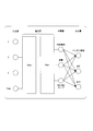
- FIG. 3 is a diagram schematically showing an example of a battery model generated in the battery identifying system 1.
- the example of the battery model shown in FIG. 3 is an example of the battery model generated by the model generation unit 130 when the battery characteristic information includes the elapsed time.
- the battery model has an input layer, a hidden layer, and an output layer.
- the hidden layer of the battery model includes, for example, one or more CNN (Convolution Neural Network).
- the CNN includes Conv (convolutional layer) and Pool (pooling layer).
- the current (I), voltage (V), temperature (T), and lifetime elapsed time (Time) of the secondary battery BT are input as input information to the input layer of the battery model.
- the lifetime elapsed time is the time (elapsed time) that has elapsed after the vehicle-mounted battery 22 was manufactured.
- the middle layer of the battery model outputs the internal resistance, capacity, and SOC-OCV (Open Circuit Voltage) curve of the secondary battery BT as output information.
- the output layer of the battery model is connected to the intermediate layer by, for example, full connection, and outputs the battery type, SOC, and output of the secondary battery BT as presentation information.
- the hidden layer parameters are optimized by performing machine learning with the input to the input layer as learning data and the data to be output from the intermediate layer or the output layer as teacher data.
- the model generation unit 130 generates a battery model by inputting the current, voltage, temperature, and lifetime elapsed time of the secondary battery BT to the input layer and performing machine learning.
- the model generation unit 130 performs machine learning to update the corresponding battery model. Then, the model generation unit 130 stores the generated or updated battery model in the storage unit 150.
- the control unit 120 grasps the battery characteristics of the secondary battery BT built in the in-vehicle battery 22 mounted on the electric vehicle 20 by using the battery model. More specifically, the control unit 120 uses the presentation information including the battery type, the SOC, and the output, which is output from the output layer of the battery model. Then, the control unit 120 confirms whether or not the control information corresponding to the secondary battery BT having the same battery characteristic is stored in the storage unit 150 based on the grasped battery characteristic of the secondary battery BT. The control unit 120 can also determine whether or not the secondary battery BT is out of order, based on the output information output from the middle layer of the battery model.
- the control information creation unit 140 formulates an optimal discharge control method for the secondary battery BT contained in the vehicle-mounted battery 22 mounted on the electric vehicle 20, and outputs the control information of the ECU. create. More specifically, the control information creation unit 140 outputs the output including the internal resistance, the capacity, and the SOC-OCV curve output from the middle layer of the battery model when formulating the discharge control method of the secondary battery BT. Use information.
- the control information creation unit 140 presents information about the secondary battery BT that has formulated the discharge control method by using the presentation information including the battery type, SOC, and output that are output from the output layer of the battery model. You can also do it.
- FIG. 4 is a sequence diagram showing the flow of processing in the battery identifying system 1.
- FIG. 4 shows an example of processing between the battery identifying device 100 and the three electric vehicles 20 of the electric vehicle 20A, the electric vehicle 20B, and the electric vehicle 20C. Then, the battery characteristic information is transmitted from each of the three electric vehicles 20, and the battery identifying device 100 transmits the control information to each of the three electric vehicles 20.
- the information acquiring unit 21A (more specifically, the battery sensor 250) included in the electric vehicle 20A is a secondary battery BT built in the in-vehicle battery 22A.
- the current, voltage, and temperature (including lifetime elapsed time) are detected (step S11A).
- the information acquisition unit 21B (more specifically, the battery sensor 250) included in the electric vehicle 20B causes the current, voltage, and temperature (including lifetime elapsed time) of the secondary battery BT included in the vehicle-mounted battery 22B. Is detected (step S11B).
- the information acquisition unit 21C (more specifically, the battery sensor 250) included in the electric vehicle 20C causes the current, voltage, and temperature (including lifetime elapsed time) of the secondary battery BT built in the vehicle-mounted battery 22C. Is detected (step S11C).
- the information acquisition unit 21A transmits the detected current, voltage, and temperature (including lifetime elapsed time) of the secondary battery BT to the battery identifying apparatus 100 as the battery characteristic information (step S12A).
- the communication unit 110 included in the battery identifying device 100 receives the battery characteristic information transmitted by the information acquisition unit 21A of the electric vehicle 20A.
- the information acquisition unit 21B transmits the detected current, voltage, and temperature (including lifetime elapsed time) of the secondary battery BT to the battery identifying device 100 as the battery characteristic information (step S12B).
- the communication unit 110 included in the battery identifying device 100 receives the battery characteristic information transmitted by the information acquisition unit 21B of the electric vehicle 20B.
- the information acquisition unit 21C also transmits the detected current, voltage, and temperature (including lifetime elapsed time) of the secondary battery BT to the battery identifying device 100 as the battery characteristic information (step S12C).
- the communication unit 110 included in the battery identifying device 100 receives the battery characteristic information transmitted by the information acquisition unit 21C of the electric vehicle 20C.
- the control unit 120 included in the battery identifying apparatus 100 has the battery characteristic information (current, voltage, and the like) of the secondary battery BT transmitted by the electric vehicle 20A, the electric vehicle 20B, and the electric vehicle 20C received by the communication unit 110.
- the temperature (including lifetime elapsed time) information is acquired, stored in the storage unit 150, and collected (step S21).
- the control unit 120 instructs the model generation unit 130 to generate a battery model based on the battery characteristic information stored in the storage unit 150.
- the model generation unit 130 is built in the in-vehicle battery 22 mounted on each electric vehicle 20 based on the battery characteristic information stored in the storage unit 150 in response to an instruction from the control unit 120.
- a battery model of the existing secondary battery BT is generated (step S22). More specifically, the model generation unit 130 uses the battery based on the states such as current, voltage, and temperature included in the battery characteristic information of the secondary battery BT incorporated in the vehicle-mounted battery 22A mounted on the electric vehicle 20A. Generate a model.
- the model generation unit 130 also generates a battery model based on the states such as current, voltage, and temperature included in the battery characteristic information of the secondary battery BT built in the onboard battery 22B mounted on the electric vehicle 20B. .. In addition, the model generation unit 130 generates a battery model based on states such as current, voltage, and temperature included in the battery characteristic information of the secondary battery BT incorporated in the vehicle-mounted battery 22C mounted on the electric vehicle 20C. .. Then, the model generation unit 130 stores the generated battery models in the storage unit 150.
- control unit 120 determines the battery characteristics of the secondary battery BT built in the in-vehicle battery 22 currently installed in each electric vehicle 20, based on each battery model generated by the model generation unit 130. Understand (step S23). More specifically, control unit 120 grasps the battery characteristics of secondary battery BT incorporated in vehicle-mounted battery 22A currently mounted on electric vehicle 20A. The control unit 120 also grasps the battery characteristics of the secondary battery BT built in the vehicle-mounted battery 22B currently mounted on the electric vehicle 20B. The control unit 120 also grasps the battery characteristics of the secondary battery BT incorporated in the vehicle-mounted battery 22C currently mounted on the electric vehicle 20C.
- the control unit 120 confirms whether or not the control information corresponding to the secondary battery having the same battery characteristic as the grasped battery characteristic of each secondary battery BT is already stored in the storage unit 150 (Ste S24). More specifically, the control unit 120 grasps by searching the plurality of battery characteristics stored in the storage unit 150 for the same battery characteristic as the grasped battery characteristic of each secondary battery BT. It is confirmed whether control information corresponding to the battery characteristics of each secondary battery BT is stored. Note that the control unit 120 may search the battery characteristics stored in the storage unit 150, including the battery characteristics approximate to the battery characteristics of each of the secondary batteries BT that have been grasped. In this case, when the same battery characteristic is not searched and only the approximate battery characteristic is searched, the control information corresponding to the searched approximate battery characteristic corresponds to the grasped battery characteristic of the secondary battery BT. It may be treated as control information.
- step S24 when it is confirmed that the storage unit 150 stores the control information corresponding to the secondary battery having the same battery characteristic as the grasped battery characteristic of each secondary battery BT, the control unit 120 determines that It proceeds to step S31A.
- step S24 when it is confirmed in step S24 that the control information corresponding to the secondary battery having the same battery characteristic as the grasped battery characteristic of each secondary battery BT is not stored in the storage unit 150, the control unit 120 Instructs the control information creation unit 140 to create control information based on the battery model generated by the model generation unit 130 and stored in the storage unit 150. Accordingly, the control information creation unit 140 is built in the in-vehicle battery 22 mounted on each electric vehicle 20 based on the battery model stored in the storage unit 150 in response to the instruction from the control unit 120. ECU control information corresponding to the existing secondary battery BT is generated (step S25).
- control information creation unit 140 performs optimal discharge control of the secondary battery BT based on the battery model of the secondary battery BT built in the in-vehicle battery 22A mounted on the electric vehicle 20A. Develop a method and create optimized ECU control information. In addition, the control information creation unit 140 formulates an optimal discharge control method for the secondary battery BT based on the battery model of the secondary battery BT built in the in-vehicle battery 22B mounted on the electric vehicle 20B. , Creates optimized ECU control information. In addition, the control information creation unit 140 formulates an optimal discharge control method for the secondary battery BT based on the battery model of the secondary battery BT built in the in-vehicle battery 22C mounted on the electric vehicle 20C. , Creates optimized ECU control information. Then, the control information creation unit 140 stores the created control information in the storage unit 150.
- the control unit 120 transmits to the electric vehicle 20A the control information of the ECU, which is created by the control information creating unit 140 and corresponds to the secondary battery BT contained in the vehicle-mounted battery 22A mounted on the electric vehicle 20A. Instruct the communication unit 110. Thereby, communication unit 110 transmits the control information of the instructed ECU stored in storage unit 150 to electric vehicle 20A (step S31A). In addition, the control unit 120 transmits, to the electric vehicle 20B, control information of the ECU corresponding to the secondary battery BT built in the vehicle-mounted battery 22B mounted on the electric vehicle 20B, which is created by the control information creating unit 140. Instruct the communication unit 110.
- communication unit 110 transmits the control information of the instructed ECU stored in storage unit 150 to electric vehicle 20B (step S31B).
- the control unit 120 transmits to the electric vehicle 20C the control information of the ECU, which is created by the control information creating unit 140 and corresponds to the secondary battery BT incorporated in the in-vehicle battery 22C mounted on the electric vehicle 20C. Instruct the communication unit 110. Accordingly, communication unit 110 transmits the control information of the instructed ECU stored in storage unit 150 to electric vehicle 20C (step S31C).
- the battery identification device 100 is built in the vehicle-mounted battery 22 mounted on each electric vehicle 20 based on the battery characteristic information acquired from each electric vehicle 20.
- a battery model that models the characteristics of the secondary battery is generated, and based on the generated battery model, control information of the ECU provided in each electric vehicle 20 is generated and transmitted.
- the ECU provided in each electric vehicle 20 controls the drive of the electric motor M based on the control information transmitted by the battery identifying device 100.
- the battery identifying device 100 that configures the battery identifying system 1 generates a battery model that models the characteristics of the secondary battery BT provided in the electric vehicle 20. Then, in the battery identification system 1, the battery identification device 100 creates control information of the ECU included in the electric vehicle 20 based on the generated battery model and transmits the control information to the electric vehicle 20.
- the ECU provided in the electric vehicle 20 to which the battery identifying system 1 according to the embodiment of the present invention is applied is optimized for the secondary battery BT built in the on-vehicle battery 22A currently installed.
- the drive of the electric motor M that is, the traveling of the electric vehicle 20 can be controlled based on the control information. As a result, the electric vehicle 20 to which the battery identifying system 1 according to the embodiment of the present invention is applied can travel smoothly.
- the battery identifying apparatus 100 stores (collects) the generated battery model and the created ECU control information in the storage unit 150. Therefore, in the embodiment for carrying out the present invention, even when the new vehicle-mounted battery 22 is mounted on the electric vehicle 20, the battery characteristic close to the battery characteristic of the secondary battery BT built in the vehicle-mounted battery 22. It is possible to transmit the control information of the ECU created based on the above to the electric vehicle 20.
- the battery identifying apparatus 100 updates the battery model and control information stored in the storage unit 150 as needed. Therefore, in the embodiment for carrying out the present invention, the battery characteristics of the secondary battery BT incorporated in the in-vehicle battery 22 newly installed in the electric vehicle 20 are stored in the storage unit 150 as the other two. When it deviates from the battery characteristic of the secondary battery BT, it can be stored and collected (stored) in the storage unit 150 as a battery model or control information of another secondary battery BT.
- the user (user) of the electric vehicle 20 to which the battery identifying system 1 according to the embodiment of the present invention is applied can be installed in the electric vehicle 20 without worrying about the manufacturer of the on-vehicle battery 22.
- the on-vehicle battery 22 to be mounted can be selected.
- the manufacturer of the secondary battery which is about to enter the market to which the battery identification system 1 of the embodiment for implementing the present invention is applied, can supply the vehicle-mounted battery 22 to the market with confidence.
- Battery identification system 100 Battery identification device 20, 20A, 20B, 20C... Electric vehicle 110... Communication part 120... Control part 130... Model generation part 140... Control Information creation unit 150... Storage units 21, 21A, 21B, 21C... Information acquisition units 22, 22A, 22B, 22C... In-vehicle battery BT... Secondary battery NW... Network M... Electric motor 210...Drive wheel 220...Brake device 230...Vehicle sensor 240...PCU 241... Converter 242... VCU 243... Control unit 250... Battery sensor 260... Communication device 270... Display device 271... Display unit 272... Display control unit 280... Charging port 290... Converter 500. ....Charger 510... Charging cable 511... First plug 512... Second plug
Landscapes
- Engineering & Computer Science (AREA)
- Power Engineering (AREA)
- Transportation (AREA)
- Mechanical Engineering (AREA)
- General Physics & Mathematics (AREA)
- Physics & Mathematics (AREA)
- Chemical & Material Sciences (AREA)
- Electrochemistry (AREA)
- General Chemical & Material Sciences (AREA)
- Chemical Kinetics & Catalysis (AREA)
- Manufacturing & Machinery (AREA)
- Sustainable Development (AREA)
- Sustainable Energy (AREA)
- Life Sciences & Earth Sciences (AREA)
- Computer Hardware Design (AREA)
- Microelectronics & Electronic Packaging (AREA)
- Combustion & Propulsion (AREA)
- Secondary Cells (AREA)
- Electric Propulsion And Braking For Vehicles (AREA)
- Automotive Seat Belt Assembly (AREA)
- Charge And Discharge Circuits For Batteries Or The Like (AREA)
Abstract
電動車両(20)に搭載されるバッテリ(22)の特性を取得し、バッテリ特性情報として送信する情報取得部(21)と、複数の電動車両により送信されたバッテリ特性情報を収集し、収集したバッテリ特性情報に基づいて、バッテリの特性をモデル化したバッテリモデルを生成するとともに、生成したバッテリモデルに基づいて、電動車両の走行を制御するためにバッテリの特性に応じた制御情報を作成し、それぞれの電動車両に適した制御情報を提供するバッテリ特定装置(100)と、を備える。
Description
本発明は、バッテリ特定システムおよびバッテリ特定方法に関する。
本願は、2019年02月04日に、日本に出願された特願2019-018106号に基づき優先権を主張し、その内容をここに援用する。
本願は、2019年02月04日に、日本に出願された特願2019-018106号に基づき優先権を主張し、その内容をここに援用する。
近年、電気自動車(Battery Electric Vehicle:BEV)やハイブリッド電気自動車(Hybrid Electric Vehicle:HEV)など、二次電池(バッテリ)から供給される電力によって駆動される電動モータによって走行する電動車両の開発が進み、普及しはじめている。また、近年の電動車両の中には、着脱することができる構成にした二次電池(着脱式バッテリ)を利用することができるものもある。現在の電動車両においては、電動車両の提供者(製造業者)が電動車両への適合性を検証して認証したバッテリの搭載のみに限定されている。これは、電動車両における制御の観点から、電動車両の走行に必要な制御情報(例えば、電動車両に備える電子制御ユニット(Electronic Control Unit:ECU)における制御ソフトウェアなど)を、二次電池の特性(以下、「バッテリ特性」という)に合わせて最適化しているからである。一方、近年では、電動車両において利用することができる二次電池を内蔵したバッテリパック(以下、「車載バッテリ」という)の規格化が検討されている。
ところで、二次電池は、様々な製造業者によって開発、製造され、安価に販売がされているものもある。このため、車載バッテリの規格化が進んでいった場合でも、外形や大きさなどに関しては統一化されるものの、内蔵する二次電池のバッテリ特性に関しての統一化までには至らないことが予想される。すると、電動車両に利用される車載バッテリには、様々なバッテリ特性の二次電池が内蔵されることが考えられる。この場合、電動車両の使用者(ユーザー)は、形状は同じであるが認証はされていない車載バッテリを選択して、電動車両に搭載してしまうことも考えられる。
このことから、電動車両の製造業者は、電動車両における制御の観点から、認証をしていない車載バッテリも含め、車載バッテリに内蔵されている二次電池のバッテリ特性ごと(つまり、車載バッテリごと)に最適化した制御情報を準備して提供するという対応が必要になってくる。このため、電動車両の製造業者は、搭載される可能性がある様々な車載バッテリのバッテリ特性を取得する必要がある。
これに関して、バッテリ特性を取得するための種々の技術が開示されている(特許文献1および特許文献2参照)。特許文献1には、バッテリを内蔵したバッテリパックと、そのバッテリパックが接続される少なくとも一種類の接続機器とを備えた測定システムが開示されている。特許文献1に開示された技術では、バッテリからの放電電流が第1測定レンジで検出され、バッテリへの充電電流が第1測定レンジよりも小さい第2測定レンジで検出され、バッテリの充電容量が算出される。また、特許文献2には、二次電池と、二次電池のセル電圧を検出する電圧検出手段と、二次電池の充放電電流を検出する電流検出手段と、充電器および負荷機器の少なくとも一方と通信を行う通信手段と、通信手段を介して充電器へ充電電流を要求し、電圧検出手段および電流検出手段の検出結果に応答して二次電池への充電電流を制御する充電制御手段とを備えた電池パックが記載されている。特許文献2に開示された技術では、充電制御手段が、通信手段を介して充電器または負荷機器から電池パックの充放電端子の端子電圧を受信し、その端子電圧と、電圧検出手段によって検出されるセル電圧との差を、電流検出手段によって検出される電流値で除算することで、充放電に使用される充放電経路の経路抵抗を求める。
しかしながら、二次電池は、様々な製造業者によって開発、製造、販売され、さらには、電動車両の使用者(ユーザー)によって選択されるため、将来にわたって様々な車載バッテリのバッテリ特性に最適化した制御情報を提供し続けることは、電動車両の製造業者における絶大な負荷となり、困難である。
本発明は、上記の課題認識に基づいてなされたものであり、バッテリの特性に関する情報を取得し収集することによって、特性が異なるバッテリに適した制御情報を提供するためのバッテリ特定システムおよびバッテリ特定方法を提供することを目的としている。
(1):上記目的を達成するため、本発明の一態様に係るバッテリ特定システムは、電動車両に搭載されるバッテリの特性を取得し、バッテリ特性情報として送信する情報取得部と、複数の電動車両により送信された前記バッテリ特性情報を収集し、収集した前記バッテリ特性情報に基づいて、前記バッテリの特性をモデル化したバッテリモデルを生成するとともに、生成した前記バッテリモデルに基づいて、電動車両の走行を制御するために前記バッテリの特性に応じた制御情報を作成し、それぞれの電動車両に適した前記制御情報を提供するバッテリ特定装置と、を備える。
(2):上記(1)の態様において、前記バッテリ特定装置は、前記バッテリの特性を把握するとともに、前記バッテリモデルの生成および前記制御情報の作成を指示する制御部と、収集した前記バッテリ特性情報に基づいて前記バッテリモデルを生成するモデル生成部と、前記バッテリモデルに基づいて、前記バッテリの特性に適した前記制御情報を作成する制御情報作成部と、前記電動車両により送信された前記バッテリ特性情報を受信し、当該電動車両に適した前記制御情報を送信する通信部と、を備えるものである。
(3):上記(2)の態様において、前記バッテリ特性情報は、前記バッテリの少なくとも電流、電圧、および温度を含み、前記モデル生成部は、少なくとも前記電流、前記電圧、および前記温度が入力情報として入力され、前記バッテリの内部抵抗、容量、およびSOC-OCVカーブの少なくともいずれかを出力情報として出力するバッテリモデルを生成し、前記制御情報作成部は、前記バッテリモデルの前記出力情報を利用することによって、前記制御情報を作成するものである。
(4):上記(3)の態様において、前記モデル生成部は、前記バッテリのバッテリ種別、SOC、および出力の少なくともいずれかを提示情報として出力するバッテリモデルを生成し、前記制御部は、前記バッテリモデルの前記提示情報を利用することによって、前記バッテリの特性を把握するものである。
(5):上記(4)の態様において、前記制御部は、把握した前記バッテリの特性が、当該電動車両の走行を制御するのに適していない場合、当該把握した前記バッテリの特性に関する情報を通信部に送信させるものである。
(6):上記(1)~(5)のいずれか一態様において、前記情報取得部は、前記バッテリの電流、電圧、および温度を検出するバッテリ検出部と、検出した前記電流、前記電圧、および前記温度を送信する通信装置と、を備えるものである。
(7):また、本発明の一態様に係るバッテリ特定方法は、情報取得部が、電動車両に搭載されるバッテリの特性を取得し、バッテリ特性情報として送信し、バッテリ特定装置が、複数の電動車両に備えた前記情報取得部により送信された前記バッテリ特性情報を収集し、収集した前記バッテリ特性情報に基づいて、前記バッテリの特性をモデル化したバッテリモデルを生成するとともに、生成した前記バッテリモデルに基づいて、電動車両の走行を制御するために前記バッテリの特性に応じた制御情報を作成し、それぞれの電動車両に適した前記制御情報を提供する。
上述した(1)~(7)の構成によれば、情報取得部とバッテリ特定装置とを備え、情報取得部が、電動車両に搭載されるバッテリの特性を取得し、バッテリ特性情報として送信し、バッテリ特定装置が、複数の電動車両に備えた前記情報取得部により送信された前記バッテリ特性情報を収集し、収集した前記バッテリ特性情報に基づいて、前記バッテリの特性をモデル化したバッテリモデルを生成するとともに、生成した前記バッテリモデルに基づいて、電動車両の走行を制御するために前記バッテリの特性に応じた制御情報を作成し、それぞれの電動車両に適した前記制御情報を提供するため、特性が異なるバッテリに適した制御情報を提供することができる。
以下、本発明の実施形態について、図面を参照して説明する。図1は、本実施形態のバッテリ特定システムの概略構成を示すブロック図である。図1に示すバッテリ特定システム1は、バッテリ特定装置100と、電動車両20とを含む。また、バッテリ特定装置100は、通信部110と、制御部120と、モデル生成部130と、制御情報作成部140と、記憶部150とを含む。また、電動車両20は、情報取得部21と、車載バッテリ22とを含む。つまり、車載バッテリ22が、電動車両20に搭載されている。
バッテリ特定システム1は、バッテリ特定装置100と、電動車両20に備える情報取得部21とによって構成される。バッテリ特定システム1では、バッテリ特定装置100と情報取得部21とが、ネットワークNWを介して接続されている。なお、ネットワークNWは、例えば、インターネット、WAN(Wide Area Network)、LAN(Local Area Network)、プロバイダ装置、無線基地局などを含む無線通信の通信網である。
なお、図1に示すバッテリ特定システム1では、3台の電動車両20(電動車両20A、電動車両20B、電動車両20C)が含まれている場合の一例を示しているが、バッテリ特定システム1に含まれる電動車両20は、3台とは限らず、1台、2台、または4台以上であってもよい。以下の説明においては、それぞれの電動車両20に備える情報取得部21と車載バッテリ22とのそれぞれを区別するため、それぞれの構成要素の符号の後に、電動車両20を区別するための「A」、「B」または「C」の符号を付与して表す。
バッテリ特定システム1は、複数の電動車両20から、搭載されている車載バッテリ22に内蔵されている二次電池の特性(バッテリ特性)を取得して収集する。ここで、電動車両20は、常に同じ車載バッテリ22を搭載しているとは限らず、異なる車載バッテリ22に載せ替えていることもある。このため、バッテリ特定システム1は、実際に車載バッテリ22を搭載して走行しているそれぞれの電動車両20から、現在搭載している車載バッテリ22に内蔵されている二次電池のバッテリ特性を取得する。これにより、バッテリ特定システム1では、異なる車載バッテリ22も含め、複数の電動車両20において再度利用される可能性がある車載バッテリ22に内蔵されている二次電池のバッテリ特性も収集することができる。
そして、バッテリ特定システム1では、収集したバッテリ特性に基づいて、それぞれの車載バッテリ22(つまり、車載バッテリ22に内蔵されている二次電池)の特性をモデル化したバッテリモデルを生成し、車載バッテリ22の特性を把握する。そして、バッテリ特定システム1は、把握した車載バッテリ22の特性に基づいて、電動車両20に備えているECU(電子制御ユニット:Electronic Control Unit)が電動車両20の走行を制御するのに最適化した制御情報(例えば、制御ソフトウェアや制御パラメータなど)を、それぞれの車載バッテリ22ごとに生成する。そして、バッテリ特定システム1は、電動車両20に現在搭載されている車載バッテリ22に対して最適化した制御情報を、それぞれの電動車両20(より具体的には、ECU)に提供する。
なお、バッテリ特定システム1は、把握した車載バッテリ22の特性が、電動車両20の走行を制御するのに適していない場合には、そのことを電動車両20に通知することもできる。
電動車両20は、車載バッテリ22から供給される電力によって駆動される電動モータによって走行する車両である。なお、電動車両20は、例えば、四輪の車両のみならず、鞍乗り型の二輪の車両や、三輪(前一輪かつ後二輪の他に、前二輪かつ後一輪の車両も含む)の車両、さらには、アシスト式の自転車など、車載バッテリ22から供給される電力によって駆動される電動モータによって走行する電動車両の全般が含まれる。
車載バッテリ22は、充電と放電とを繰り返すことができる二次電池を内蔵し、電動車両20に搭載される蓄電装置である。なお、車載バッテリ22は、電動車両20に対して着脱自在に装着される、例えば、カセット式の蓄電装置(着脱式バッテリ)であってもよい。車載バッテリ22は、内蔵している二次電池の放電によって、電動車両20に備える電動モータに電力を供給する。車載バッテリ22に内蔵する二次電池としては、例えば、鉛蓄電池、ニッケル・水素電池、リチウムイオン電池、ナトリウムイオン電池などの他、電気二重層キャパシタなどのキャパシタ、または二次電池とキャパシタとを組み合わせた複合電池なども考えられる。なお、本発明においては、車載バッテリ22および車載バッテリ22に内蔵する二次電池の構成に関しては特に規定しない。なお、車載バッテリ22が着脱式バッテリの構成である場合、車載バッテリ22は、複数の電動車両20で利用することができる。つまり、車載バッテリ22は、複数の電動車両20で共用することができる。
情報取得部21は、電動車両20に搭載されている車載バッテリ22に内蔵されている二次電池の状態を検出することによって、二次電池のバッテリ特性を取得する。ここで、情報取得部21が取得するバッテリ特性は、二次電池の電流、電圧、温度などの状態(値)が含まれる。また、バッテリ特性には、車載バッテリ22(または二次電池)が製造されたときからの経過時間を含んでもよい。また、バッテリ特性には、車載バッテリ22に排他的に割り当てられたシリアル番号などの識別情報(バッテリID)を含んでもよい。情報取得部21は、取得したバッテリ特性の情報(以下、「バッテリ特性情報」という)を、不図示の通信装置によって、ネットワークNWを介してバッテリ特定装置100に送信する。
バッテリ特定装置100は、それぞれの電動車両20に備える情報取得部21により送信されたバッテリ特性情報を収集し、収集したバッテリ特性情報に基づいて、車載バッテリ22の特性をモデル化したバッテリモデルを生成する。より具体的には、バッテリ特定装置100は、バッテリ特性情報に含まれる二次電池の電流、電圧、温度などの状態に基づいて、車載バッテリ22に内蔵されている二次電池のバッテリモデルを生成する。ここで、バッテリモデルは、二次電池の特性の把握や、充放電の制御方法の策定などに用いることができる。なお、バッテリ特性情報に経過時間を含んでいる場合、バッテリ特定装置100は、経過時間も含めて、バッテリモデルを生成してもよい。この場合、バッテリモデルは、二次電池の寿命の推定や故障の判定などにも用いることができる。
また、バッテリ特定装置100は、バッテリモデルに基づいて二次電池の特性を把握し、最適な放電制御の方法を策定する。つまり、バッテリ特定装置100は、車載バッテリ22が搭載された電動車両20において電動モータに電力を供給する際の最適な電力供給方法を策定する。そして、バッテリ特定装置100は、電動車両20に備えるECUが、策定した電力供給方法で電動モータに電力を供給する、つまり、ECUが電動車両20の走行を制御するために最適化した制御情報を作成する。ここで、バッテリ特定装置100が作成するECUの制御情報は、それぞれの電動車両20に備えるECU、つまり、複数のECUに共通の制御情報であってもよいし、それぞれのECUごとの制御情報であってもよい。そして、バッテリ特定装置100は、作成した制御情報を、ネットワークNWを介して、バッテリ特性情報を送信してきた電動車両20に備える情報取得部21に送信する。
なお、バッテリ特定装置100は、例えば、バッテリモデルに基づいて、推定した二次電池の寿命の時期が近づいてきたり、二次電池の故障が判定されたりなど、電動車両20に現在搭載されている車載バッテリ22が走行を制御するのに適していない場合には、このことを表す情報を、バッテリ特性情報を送信してきた電動車両20に備える情報取得部21に送信する。これにより、情報取得部21は、電動車両20の使用者(ユーザー)に送信された情報を通知することができる。
なお、バッテリ特定装置100に備えるそれぞれの構成要素は、例えば、CPU(Central Processing Unit)などのプロセッサと、プログラムを記憶した記憶装置(非一過性の記憶媒体を備える記憶装置)とを備え、プロセッサがプログラム実行することで各種機能を実現する。また、バッテリ特定装置100に備えるそれぞれの構成要素の機能のうち一部または全部は、LSI(Large Scale Integration)やASIC(Application Specific Integrated Circuit)、FPGA(Field-Programmable Gate Array)、GPU(Graphics Processing Unit)などのハードウェア(回路部;circuitryを含む)によって実現されてもよいし、ソフトウェアとハードウェアの協働によって実現されてもよい。また、バッテリ特定装置100に備えるそれぞれの構成要素の機能のうち一部または全部は、専用のLSIによって実現されてもよい。また、プログラムは、予めHDD(Hard Disk Drive)やフラッシュメモリなどの記憶装置(非一過性の記憶媒体を備える記憶装置)に格納されていてもよいし、DVDやCD-ROMなどの着脱可能な記憶媒体(非一過性の記憶媒体)に格納されており、記憶媒体がドライブ装置に装着されることでインストールされてもよい。また、バッテリ特定装置100は、クラウドコンピューティングシステムに組み込まれたサーバ装置や記憶装置に実現されてもよい。この場合、クラウドコンピューティングシステムにおける複数のサーバ装置や記憶装置によって、バッテリ特定装置100の機能が実現されてもよい。
通信部110は、電動車両20に備える情報取得部21との間で通信を行って情報のやり取りをする。より具体的には、通信部110は、それぞれの電動車両20に備える情報取得部21により送信されたバッテリ特性情報を受信する。つまり、通信部110は、電動車両20Aに備える情報取得部21Aにより送信された車載バッテリ22Aのバッテリ特性情報と、電動車両20Bに備える情報取得部21Bにより送信された車載バッテリ22Bのバッテリ特性情報と、電動車両20Cに備える情報取得部21Cにより送信された車載バッテリ22Cのバッテリ特性情報とのそれぞれを受信する。また、通信部110は、後述する制御情報作成部140が作成した制御情報を、対応する電動車両20に備える情報取得部21に送信する。つまり、通信部110は、電動車両20Aに備えるECUに対応する制御情報を情報取得部21Aに、電動車両20Bに備えるECUに対応する制御情報を情報取得部21Bに、電動車両20Cに備えるECUに対応する制御情報を情報取得部21Cにそれぞれ送信する。
制御部120は、通信部110が受信したバッテリ特性情報を収集する。つまり、120は、電動車両20Aに搭載された車載バッテリ22Aのバッテリ特性情報と、電動車両20Bに搭載された車載バッテリ22Bのバッテリ特性情報と、電動車両20Cに搭載された車載バッテリ22Cのバッテリ特性情報とのそれぞれを取得する。そして、制御部120は、取得したそれぞれのバッテリ特性情報を、記憶部150に記憶させて収集する。また、制御部120は、記憶部150に記憶したバッテリ特性情報に基づいたバッテリモデルの生成を、モデル生成部130に指示する。また、制御部120は、モデル生成部130が生成したバッテリモデルに基づいて、電動車両20に現在搭載されている車載バッテリ22に内蔵されている二次電池のバッテリ特性を把握する。
なお、電動車両20A、電動車両20B、電動車両20Cのそれぞれに搭載された車載バッテリ22は、必ずしも同じ車載バッテリ22であるとは限らない。つまり、車載バッテリ22A、車載バッテリ22B、車載バッテリ22Cのそれぞれに内蔵されている二次電池は、同じ二次電池の製造業者が製造したものであるとは限らない。また、それぞれの車載バッテリ22に内蔵されている二次電池が同じ製造業者が製造したものであっても、同じ製造時期や同じ構成のものであるとは限らない。このため、制御部120は、モデル生成部130に、それぞれのバッテリ特性情報ごと、つまり、それぞれの車載バッテリ22ごとにバッテリモデルを生成させることを基本とする。そして、制御部120は、モデル生成部130が生成したバッテリモデルが同じバッテリ特性の二次電池のバッテリモデルであることが確認された後に、それぞれのバッテリモデルを統合するなどの処理を行う。一方、電動車両20が同じ車載バッテリ22を搭載している場合、モデル生成部130は、以前に電動車両20から取得したバッテリ特性情報に基づいて、すでにバッテリモデルを生成している。この場合、制御部120は、以前にモデル生成部130が生成したバッテリモデルを、モデル生成部130が今回生成したバッテリモデルに置き換えてもよいし、置き換えなくてもよい。この判断は、例えば、以前にバッテリモデルを作成した日時と、現在の日時との差が予め定めた差以上である、つまり、以前バッテリモデルを作成してから予め定めた時間が経過しているか否かによって判断してもよい。このようにして、制御部120は、重複して同じバッテリモデルを収集しないようにする。これにより、バッテリ特定システム1では、新規の車載バッテリが市場に投入されるなどした場合でも、バッテリ特性が異なる二次電池のバッテリモデルや、より新しいバッテリモデルを追加、更新して、複数収集するようにすることができる。
そして、制御部120は、把握したバッテリ特性と同じバッテリ特性をもつ二次電池に対応する制御情報が、すでに記憶部150に記憶されているか否かを確認する。この結果、同じバッテリ特性の二次電池に対応する制御情報が記憶部150に記憶されている場合、制御部120は、記憶さえている制御情報の送信を通信部110に指示し、バッテリ特性情報を送信してきた電動車両20に送信させる。一方、同じバッテリ特性の二次電池に対応する制御情報が記憶部150に記憶されていない場合、制御部120は、モデル生成部130が生成したバッテリモデルに基づいた制御情報の作成を、制御情報作成部140に指示する。その後、制御部120は、制御情報作成部140が作成した制御情報の送信を通信部110に指示し、バッテリ特性情報を送信してきた電動車両20に送信させる。
また、制御部120は、把握したバッテリ特性が、電動車両20の走行を制御するのに適していない場合には、そのことを表す二次電池に関する情報の送信を通信部110に指示し、バッテリ特性情報を送信してきた電動車両20に送信させる。
モデル生成部130は、制御部120からの指示に応じて、制御部120が収集して記憶部150に記憶させたバッテリ特性情報に基づいて車載バッテリ22に内蔵されている二次電池のバッテリモデルを生成する。より具体的には、モデル生成部130は、バッテリ特性情報に含まれる二次電池の電流、電圧、温度などの状態に基づいてそれぞれの二次電池の特性をモデル化したバッテリモデルを生成する。なお、モデル生成部130は、すでに同じ二次電池のバッテリモデルを生成している場合には、バッテリ特性情報に含まれる二次電池の電流、電圧、温度などの状態に基づいて生成したバッテリモデルに更新する。そして、モデル生成部130は、生成または更新したバッテリモデルを、記憶部150に記憶させる。なお、バッテリ特性情報に経過時間を含んでいる場合、モデル生成部130は、経過時間も含めてバッテリモデルを生成し、生成したバッテリモデルを、記憶部150に記憶させる。
制御情報作成部140は、制御部120からの指示に応じて、モデル生成部130が生成して記憶部150に記憶させたバッテリモデルに基づいて、二次電池に最適な放電制御の方法を策定し、ECUの制御情報を作成する。そして、制御情報作成部140は、作成した制御情報を、記憶部150に記憶させる。なお、電動車両20A、電動車両20B、電動車両20Cのそれぞれは、同じ車種の車両であるとは限らない。このため、それぞれの電動車両20に備えるECUは、同じ制御方法で電動モータの駆動を制御することによって電動車両20の走行を制御するとは限らない。このため、制御部120は、市場に流通している電動車両に備えるECUの種類ごとに、最適化した制御情報を作成する。なお、制御情報作成部140は、同じ二次電池のバッテリモデルが更新された場合には、更新されたバッテリモデルに基づいて最適化したECUの制御情報を作成し、記憶部150に記憶している対応する制御情報を更新する。
記憶部150は、バッテリ特定装置100において行われるそれぞれの処理段階の様々なデータを記憶する。記憶部150は、ROM(Read Only Memory)やRAM(Random Access Memory)、HDD、フラッシュメモリなどの記憶装置(メモリ)によって構成される。なお、バッテリ特定装置100がクラウドコンピューティングシステムに組み込まれたサーバ装置や記憶装置に実現されている場合、記憶部150は、バッテリモデルや制御情報を記憶したクラウドコンピューティングシステムにおける記憶装置、つまり、データベースとして実現される。
このような構成によって、バッテリ特定システム1では、それぞれの電動車両20から、現在搭載されている車載バッテリ22のバッテリ特性情報を取得し、取得したバッテリ特性情報に基づいて、現在搭載されている車載バッテリ22を把握し、車載バッテリ22に対して最適化したECUの制御情報を、対応する電動車両20に提供する。これにより、電動車両20に備えるECUは、最適化された制御情報に基づいて、電動車両20の走行を制御することができる。このことにより、電動車両20の使用者(ユーザー)は、電動車両20に搭載する車載バッテリ22の製造業者を気にすることなく、車載バッテリ22を選択することができる。また、二次電池の製造業者は、電動車両20の市場に車載バッテリ22を供給する業者として参入することができる。
次に、バッテリ特定システム1を構成する情報取得部21を備える電動車両20の一例について説明する。図2は、バッテリ特定システム1に含まれる電動車両20の構成の一例を示す図である。図2に示す電動車両20は、例えば、電動モータMと、駆動輪210と、ブレーキ装置220と、車両センサ230と、PCU(Power Control Unit)240と、バッテリセンサ250と、通信装置260と、表示装置270と、充電口280と、コンバータ290とを含む。バッテリ特定システム1において情報取得部21は、バッテリセンサ250と、通信装置260とによって構成される。
電動モータMは、例えば、三相交流電動機である。電動モータMの回転子(ロータ)は、駆動輪210に連結される。電動モータMは、車載バッテリ22に内蔵された二次電池BTから供給される電力によって駆動され、回転の動力を駆動輪210に伝達する。また、電動モータMは、電動車両20の減速時に、電動車両20の運動エネルギーを用いて発電する。
ブレーキ装置220は、例えば、ブレーキキャリパーと、ブレーキキャリパーに油圧を伝達するシリンダと、シリンダに油圧を発生させるモータとを含む。ブレーキ装置220は、電動車両20の運転者による減速指示を受け付ける操作子の一例であるブレーキペダル(不図示)に対する電動車両20の使用者(運転者)による操作によって発生した油圧を、マスターシリンダを介してシリンダに伝達する機構をバックアップとして備えてもよい。なお、ブレーキ装置220の構成は、上述した構成に限定されるものではなく、マスターシリンダの油圧をシリンダに伝達する電子制御式油圧ブレーキ装置であってもよい。
車両センサ230は、アクセル開度センサと、車速センサと、ブレーキ踏量センサとを含む。アクセル開度センサは、電動車両20の運転者による加速指示を受け付ける操作子の一例であるアクセルペダルに取り付けられ、運転者によるアクセルペダルの操作量を検出し、検出した操作量をアクセル開度として制御部243に出力する。また、車速センサは、例えば、電動車両20のそれぞれの車輪に取り付けられた車輪速センサと速度計算機とを含み、車輪速センサにより検出された車輪速を統合して電動車両20の速度(車速)を導出し、制御部243および表示装置270に出力する。また、ブレーキ踏量センサは、ブレーキペダルに取り付けられ、運転者によるブレーキペダルの操作量を検出し、検出した操作量をブレーキ踏量として制御部243に出力する。
PCU240は、例えば、変換器241と、VCU(Voltage Control Unit)242と、制御部243とを含む。なお、図2においては、上述した構成要素をまとめてPCU240として構成している一例を示したが、これはあくまで一例であり、電動車両20においてこれらの構成要素は、分散的に配置されてもよい。
変換器241は、例えば、AC-DC変換器である。変換器241の直流側端子は、直流リンクDLに接続されている。直流リンクDLには、VCU242を介して二次電池BTが接続されている。変換器241は、電動モータMによって発電された交流を直流に変換して直流リンクDLに出力する。
VCU242は、例えば、DC―DCコンバータである。VCU242は、二次電池BTから供給される電力を昇圧して直流リンクDLに出力する。
制御部243は、電動車両20における走行を制御するECUである。制御部243は、例えば、モータ制御部と、ブレーキ制御部と、バッテリ・VCU制御部とを含む。モータ制御部、ブレーキ制御部、およびバッテリ・VCU制御部のそれぞれは、例えば、モータECU、ブレーキECU、バッテリECUというような別体の制御装置に置き換えられてもよい。
モータ制御部は、車両センサ230に備えるアクセル開度センサからの出力に基づいて、電動モータMの駆動を制御する。モータ制御部は、バッテリ特定装置100から制御情報が送信されてきていない場合には、例えば、初期値の制御情報に基づいて電動モータMの駆動を制御し、バッテリ特定装置100から制御情報が送信されてきた場合には、送信されてきた制御情報に基づいて電動モータMの駆動を制御する。
ブレーキ制御部は、車両センサ230に備えるブレーキ踏量センサからの出力に基づいて、ブレーキ装置220を制御する。
バッテリ・VCU制御部は、二次電池BTに取り付けられたバッテリセンサ250からの出力に基づいて、二次電池BTのSOC(State of Charge)を算出し、算出したSOCをVCU242および表示装置270に出力する。これにより、VCU242は、バッテリ・VCU制御部からの指示に応じて、直流リンクDLの電圧を昇圧させる。また、表示装置270は、バッテリ・VCU制御部が算出したSOCの情報などを表示させる。
二次電池BTは、車載バッテリ22に内蔵された二次電池であり、電動車両20の外部の充電器500から導入される電力を蓄え、電動車両20の走行のために蓄えた電力を放電する。
バッテリセンサ250は、例えば、電流センサ、電圧センサ、および温度センサを含むバッテリ検出部である。バッテリセンサ250は、電流センサによって二次電池BTの電流を検出し、電圧センサによって二次電池BTの電圧を検出し、温度センサによって二次電池BTの温度を検出する。バッテリセンサ250は、検出した二次電池BTの電流、電圧、および温度などの情報を、制御部243および通信装置260に出力する。
通信装置260は、セルラー網やWiFi(登録商標)網などの無線通信の通信網(移動体通信網)と接続するための無線モジュールを含む。通信装置260は、バッテリセンサ250から出力された二次電池BTの電流、電圧、温度などの情報をバッテリ特性情報として、ネットワークNW(図1参照)を介して、バッテリ特定装置100に送信する。このとき、通信装置260は、電動車両20自体の識別情報(車両ID)や車載バッテリ22の識別情報(バッテリID)などの識別情報を、バッテリ特性情報に付加してバッテリ特定装置100に送信してもよい。また、通信装置260は、ネットワークNWを介してバッテリ特定装置100により送信された情報を受信する。より具体的には、通信装置260は、バッテリ特定装置100により送信されたECUの制御情報、つまり、制御部243の制御情報を受信する。通信装置260は、受信した制御情報を、制御部243に出力する。また、通信装置260は、バッテリ特定装置100により送信された二次電池BTに関する情報(例えば、二次電池BTの寿命の時期が近づいてきたり、二次電池BTの故障が判定されたりしたことを表すエラー情報など)を受信する。通信装置260は、受信した二次電池BTに関する情報を、表示装置270に出力する。
表示装置270は、例えば、表示部271と、表示制御部272とを含む。表示部271は、表示制御部272の制御に応じて、電動車両20における種々の情報を表示する。表示制御部272は、表示部271における情報の表示を制御する。より具体的には、表示制御部272は、制御部243から出力された電動車両20の走行制御に関する情報を、表示部271に表示させる。また、表示制御部272は、通信装置260から出力された二次電池BTに関する情報(エラー情報など)を、表示部271に表示させる。また、表示制御部272は、車両センサ230から出力された車速などの情報を表示部271に表示させる。
充電口280は、二次電池BTが接続された状態、つまり、電動車両20に車載バッテリ22を搭載している状態で二次電池BTを充電するための機構である。充電口280は、電動車両20の車体外部に向けて設けられている。充電口280には、充電ケーブル510を介して充電器500が接続される。充電器500から出力された電気は、充電ケーブル510を介して充電口280に入力(供給)される。充電ケーブル510は、第1プラグ511と第2プラグ512とを備える。第1プラグ511は、充電器500に接続され、第2プラグ512は、充電口280に接続される。また、充電ケーブル510は、電力ケーブルに付設された信号ケーブルを含む。信号ケーブルは、電動車両20と充電器500との間の通信を仲介する。このため、第1プラグ511と第2プラグ512とのそれぞれには、電力コネクタと信号コネクタとが設けられている。
コンバータ290は、二次電池BTと充電口280との間に設けられる。コンバータ290は、充電口280を介して充電器500から導入される電流、例えば、交流電流を直流電流に変換する。コンバータ290は、変換した直流電流を二次電池BTに対して出力し、二次電池BTに電力を蓄えさせる(充電する)。
次に、モデル生成部130が生成するバッテリモデルの一例について説明する。図3は、バッテリ特定システム1において生成するバッテリモデルの一例を模式的に示す図である。なお、図3に示すバッテリモデルの一例は、バッテリ特性情報に経過時間を含んでいる場合においてモデル生成部130が生成するバッテリモデルの一例である。
図3に示すバッテリモデルの一例では、バッテリモデルが、入力層と隠れ層と出力層とを有する。バッテリモデルの隠れ層は、例えば、一以上のCNN(Convolution Neural Network)を含む。CNNは、Conv(畳み込み層)とPool(プーリング層)とを含む。バッテリモデルの入力層には、二次電池BTの電流(I)、電圧(V)、温度(T)、および生涯経過時間(Time)が入力情報として入力される。ここで、生涯経過時間とは、車載バッテリ22の製造後に経過した時間(経過時間)である。バッテリモデルの中間層は、二次電池BTの内部抵抗、容量、およびSOC-OCV(Open Circuit Voltage)カーブを出力情報として出力する。また、バッテリモデルの出力層は、例えば全結合で中間層と接続され、二次電池BTのバッテリ種別、SOC、および出力を提示情報として出力する。隠れ層のパラメータは、入力層への入力を学習データとし、中間層または出力層から出力されるべきデータを教師データとして機械学習を行うことで最適化される。
モデル生成部130は、二次電池BTの電流、電圧、温度、および生涯経過時間を入力層に入力し、機械学習を行うことによって、バッテリモデルを生成する。なお、モデル生成部130は、同じ二次電池BTの電流、電圧、温度、および生涯経過時間を入力層に入力した場合には、機械学習を行うことによって、対応するバッテリモデルを更新する。そして、モデル生成部130は、生成または更新したバッテリモデルを、記憶部150に記憶させる。
制御部120は、バッテリモデルを利用することによって、電動車両20に搭載された車載バッテリ22に内蔵されている二次電池BTのバッテリ特性を把握する。より具体的には、制御部120は、バッテリモデルの出力層から出力されるバッテリ種別、SOC、および出力を含む提示情報を利用する。そして、制御部120は、把握した二次電池BTのバッテリ特性に基づいて、同じバッテリ特性の二次電池BTに対応する制御情報が記憶部150に記憶されているか否かを確認する。なお、制御部120は、バッテリモデルの中間層から出力される出力情報に基づいて、二次電池BTが故障しているか否かを判定することもできる。
制御情報作成部140は、バッテリモデルを利用することによって、電動車両20に搭載された車載バッテリ22に内蔵されている二次電池BTに最適な放電制御の方法を策定し、ECUの制御情報を作成する。より具体的には、制御情報作成部140は、二次電池BTの放電制御の方法を策定する際に、バッテリモデルの中間層から出力される内部抵抗、容量、およびSOC-OCVカーブを含む出力情報を利用する。なお、制御情報作成部140は、バッテリモデルの出力層から出力されるバッテリ種別、SOC、および出力を含む提示情報を利用することによって、放電制御の方法を策定した二次電池BTに関する情報を提示することもできる。
次に、バッテリ特定システム1における処理について説明する。図4は、バッテリ特定システム1における処理の流れを示すシーケンス図である。図4には、電動車両20A、電動車両20B、および電動車両20Cの3台の電動車両20と、バッテリ特定装置100との間の処理の一例を示している。そして、3台の電動車両20のそれぞれからバッテリ特性情報が送信され、バッテリ特定装置100が、3台の電動車両20のそれぞれに制御情報を送信する場合の一例を示している。
図4に示すバッテリ特定システム1における処理の一例では、まず、電動車両20Aに備える情報取得部21A(より具体的には、バッテリセンサ250)が、車載バッテリ22Aに内蔵されている二次電池BTの電流、電圧、および温度(生涯経過時間も含む)を検出する(ステップS11A)。また、電動車両20Bに備える情報取得部21B(より具体的には、バッテリセンサ250)が、車載バッテリ22Bに内蔵されている二次電池BTの電流、電圧、および温度(生涯経過時間も含む)を検出する(ステップS11B)。また、電動車両20Cに備える情報取得部21C(より具体的には、バッテリセンサ250)が、車載バッテリ22Cに内蔵されている二次電池BTの電流、電圧、および温度(生涯経過時間も含む)を検出する(ステップS11C)。
その後、情報取得部21Aは、検出した二次電池BTの電流、電圧、および温度(生涯経過時間も含む)の情報を、バッテリ特性情報としてバッテリ特定装置100に送信する(ステップS12A)。これにより、バッテリ特定装置100に備える通信部110は、電動車両20Aの情報取得部21Aにより送信されたバッテリ特性情報を受信する。また、情報取得部21Bは、検出した二次電池BTの電流、電圧、および温度(生涯経過時間も含む)の情報を、バッテリ特性情報としてバッテリ特定装置100に送信する(ステップS12B)。これにより、バッテリ特定装置100に備える通信部110は、電動車両20Bの情報取得部21Bにより送信されたバッテリ特性情報を受信する。また、情報取得部21Cは、検出した二次電池BTの電流、電圧、および温度(生涯経過時間も含む)の情報を、バッテリ特性情報としてバッテリ特定装置100に送信する(ステップS12C)。これにより、バッテリ特定装置100に備える通信部110は、電動車両20Cの情報取得部21Cにより送信されたバッテリ特性情報を受信する。
続いて、バッテリ特定装置100に備える制御部120は、通信部110が受信した電動車両20A、電動車両20B、および電動車両20Cにより送信された二次電池BTのバッテリ特性情報(電流、電圧、および温度(生涯経過時間も含む)の情報)のそれぞれを取得し、記憶部150に記憶させて収集する(ステップS21)。
続いて、制御部120は、記憶部150に記憶したバッテリ特性情報に基づいたバッテリモデルの生成を、モデル生成部130に指示する。これにより、モデル生成部130は、制御部120からの指示に応じて、記憶部150に記憶されているバッテリ特性情報に基づいて、それぞれの電動車両20に搭載された車載バッテリ22に内蔵されている二次電池BTのバッテリモデルを生成する(ステップS22)。より具体的には、モデル生成部130は、電動車両20Aに搭載された車載バッテリ22Aに内蔵されている二次電池BTのバッテリ特性情報に含まれる電流、電圧、温度などの状態に基づいたバッテリモデルを生成する。また、モデル生成部130は、電動車両20Bに搭載された車載バッテリ22Bに内蔵されている二次電池BTのバッテリ特性情報に含まれる電流、電圧、温度などの状態に基づいたバッテリモデルを生成する。また、モデル生成部130は、電動車両20Cに搭載された車載バッテリ22Cに内蔵されている二次電池BTのバッテリ特性情報に含まれる電流、電圧、温度などの状態に基づいたバッテリモデルを生成する。そして、モデル生成部130は、生成したそれぞれのバッテリモデルを、記憶部150に記憶させる。
続いて、制御部120は、モデル生成部130が生成したそれぞれのバッテリモデルに基づいて、それぞれの電動車両20に現在搭載されている車載バッテリ22に内蔵されている二次電池BTのバッテリ特性を把握する(ステップS23)。より具体的には、制御部120は、電動車両20Aに現在搭載されている車載バッテリ22Aに内蔵されている二次電池BTのバッテリ特性を把握する。また、制御部120は、電動車両20Bに現在搭載されている車載バッテリ22Bに内蔵されている二次電池BTのバッテリ特性を把握する。また、制御部120は、電動車両20Cに現在搭載されている車載バッテリ22Cに内蔵されている二次電池BTのバッテリ特性を把握する。
続いて、制御部120は、把握したそれぞれの二次電池BTのバッテリ特性と同じバッテリ特性をもつ二次電池に対応する制御情報が、すでに記憶部150に記憶されているか否かを確認する(ステップS24)。より具体的には、制御部120は、記憶部150に記憶されている複数のバッテリ特性の中から、把握したそれぞれの二次電池BTのバッテリ特性と同じバッテリ特性を検索することによって、把握したそれぞれの二次電池BTのバッテリ特性に対応する制御情報が記憶されているか否かを確認する。なお、制御部120は、記憶部150に記憶されているバッテリ特性の中から、把握したそれぞれの二次電池BTのバッテリ特性に近似するバッテリ特性も含めて検索してもよい。この場合、同じバッテリ特性が検索されず、近似するバッテリ特性のみが検索された場合には、検索された近似するバッテリ特性に対応する制御情報を、把握した二次電池BTのバッテリ特性に対応する制御情報として扱ってもよい。
ステップS24において、把握したそれぞれの二次電池BTのバッテリ特性と同じバッテリ特性をもつ二次電池に対応する制御情報が記憶部150に記憶されていることが確認された場合、制御部120は、ステップS31Aに進む。
一方、ステップS24において、把握したそれぞれの二次電池BTのバッテリ特性と同じバッテリ特性をもつ二次電池に対応する制御情報が記憶部150に記憶されていないことが確認された場合、制御部120は、モデル生成部130が生成して記憶部150に記憶させたバッテリモデルに基づいた制御情報の作成を、制御情報作成部140に指示する。これにより、制御情報作成部140は、制御部120からの指示に応じて、記憶部150に記憶されているバッテリモデルに基づいて、それぞれの電動車両20に搭載された車載バッテリ22に内蔵されている二次電池BTに対応するECUの制御情報を生成する(ステップS25)。より具体的には、制御情報作成部140は、電動車両20Aに搭載された車載バッテリ22Aに内蔵されている二次電池BTのバッテリモデルに基づいて、この二次電池BTに最適な放電制御の方法を策定し、最適化したECUの制御情報を作成する。また、制御情報作成部140は、電動車両20Bに搭載された車載バッテリ22Bに内蔵されている二次電池BTのバッテリモデルに基づいて、この二次電池BTに最適な放電制御の方法を策定し、最適化したECUの制御情報を作成する。また、制御情報作成部140は、電動車両20Cに搭載された車載バッテリ22Cに内蔵されている二次電池BTのバッテリモデルに基づいて、この二次電池BTに最適な放電制御の方法を策定し、最適化したECUの制御情報を作成する。そして、制御情報作成部140は、作成したそれぞれの制御情報を、記憶部150に記憶させる。
その後、制御部120は、制御情報作成部140が作成した電動車両20Aに搭載された車載バッテリ22Aに内蔵されている二次電池BTに対応するECUの制御情報の電動車両20Aへの送信を、通信部110に指示する。これにより、通信部110は、記憶部150に記憶されている指示されたECUの制御情報を、電動車両20Aに送信する(ステップS31A)。また、制御部120は、制御情報作成部140が作成した電動車両20Bに搭載された車載バッテリ22Bに内蔵されている二次電池BTに対応するECUの制御情報の電動車両20Bへの送信を、通信部110に指示する。これにより、通信部110は、記憶部150に記憶されている指示されたECUの制御情報を、電動車両20Bに送信する(ステップS31B)。また、制御部120は、制御情報作成部140が作成した電動車両20Cに搭載された車載バッテリ22Cに内蔵されている二次電池BTに対応するECUの制御情報の電動車両20Cへの送信を、通信部110に指示する。これにより、通信部110は、記憶部150に記憶されている指示されたECUの制御情報を、電動車両20Cに送信する(ステップS31C)。
このような処理の流れによって、バッテリ特定システム1では、バッテリ特定装置100が、それぞれの電動車両20から取得したバッテリ特性情報に基づいて、それぞれの電動車両20に搭載された車載バッテリ22に内蔵されている二次電池の特性をモデル化したバッテリモデルを生成し、生成したバッテリモデルに基づいて、それぞれの電動車両20に備えているECUの制御情報を生成して送信する。これにより、それぞれの電動車両20に備えているECUは、バッテリ特定装置100により送信された制御情報に基づいて電動モータMの駆動を制御する。
上記に述べたとおり、本発明を実施するための形態によれば、バッテリ特定システム1を構成する電動車両20に備えた情報取得部21が検出した二次電池BTのバッテリ特性情報に基づいて、バッテリ特定システム1を構成するバッテリ特定装置100が、電動車両20に備えた二次電池BTの特性をモデル化したバッテリモデルを生成する。そして、バッテリ特定システム1では、バッテリ特定装置100が、生成したバッテリモデルに基づいて、電動車両20に備えたECUの制御情報を作成して電動車両20に送信する。これにより、本発明を実施するための形態のバッテリ特定システム1が適用された電動車両20に備えたECUは、現在搭載された車載バッテリ22Aに内蔵されている二次電池BTに最適化された制御情報に基づいて、電動モータMの駆動、つまり、電動車両20の走行を制御することができる。このことにより、本発明を実施するための形態のバッテリ特定システム1が適用された電動車両20は、円滑に走行することができる。
しかも、本発明を実施するための形態では、バッテリ特定装置100が、生成したバッテリモデルや、作成したECUの制御情報を記憶部150に記憶して収集(蓄積)している。このため、本発明を実施するための形態では、電動車両20に新たな車載バッテリ22が搭載された場合でも、この車載バッテリ22に内蔵されている二次電池BTのバッテリ特性に近似するバッテリ特性に基づいて作成したECUの制御情報を電動車両20に送信することができる。
また、本発明を実施するための形態では、バッテリ特定装置100が、記憶部150に記憶しているバッテリモデルや制御情報を、必要に応じて更新する。このため、本発明を実施するための形態では、電動車両20に新たに搭載された車載バッテリ22に内蔵されている二次電池BTのバッテリ特性が、記憶部150に記憶している他の二次電池BTのバッテリ特性から乖離してきた場合には、別の二次電池BTのバッテリモデルや制御情報として記憶部150に記憶して収集(蓄積)することができる。
これらのことにより、本発明を実施するための形態のバッテリ特定システム1が適用された電動車両20の使用者(ユーザー)は、車載バッテリ22の製造業者を気にすることなく、電動車両20に搭載する車載バッテリ22を選択することができる。また、本発明を実施するための形態のバッテリ特定システム1が適用された市場に参入しようとしている二次電池の製造業者は、安心して市場に車載バッテリ22を供給することができる。
以上、本発明を実施するための形態について実施形態を用いて説明したが、本発明はこうした実施形態に何ら限定されるものではなく、本発明の要旨を逸脱しない範囲内において種々の変形および置換を加えることができる。
1・・・バッテリ特定システム
100・・・バッテリ特定装置
20,20A,20B,20C・・・電動車両
110・・・通信部
120・・・制御部
130・・・モデル生成部
140・・・制御情報作成部
150・・・記憶部
21,21A,21B,21C・・・情報取得部
22,22A,22B,22C・・・車載バッテリ
BT・・・二次電池
NW・・・ネットワーク
M・・・電動モータ
210・・・駆動輪
220・・・ブレーキ装置
230・・・車両センサ
240・・・PCU
241・・・変換器
242・・・VCU
243・・・制御部
250・・・バッテリセンサ
260・・・通信装置
270・・・表示装置
271・・・表示部
272・・・表示制御部
280・・・充電口
290・・・コンバータ
500・・・充電器
510・・・充電ケーブル
511・・・第1プラグ
512・・・第2プラグ
100・・・バッテリ特定装置
20,20A,20B,20C・・・電動車両
110・・・通信部
120・・・制御部
130・・・モデル生成部
140・・・制御情報作成部
150・・・記憶部
21,21A,21B,21C・・・情報取得部
22,22A,22B,22C・・・車載バッテリ
BT・・・二次電池
NW・・・ネットワーク
M・・・電動モータ
210・・・駆動輪
220・・・ブレーキ装置
230・・・車両センサ
240・・・PCU
241・・・変換器
242・・・VCU
243・・・制御部
250・・・バッテリセンサ
260・・・通信装置
270・・・表示装置
271・・・表示部
272・・・表示制御部
280・・・充電口
290・・・コンバータ
500・・・充電器
510・・・充電ケーブル
511・・・第1プラグ
512・・・第2プラグ
Claims (7)
- 電動車両に搭載されるバッテリの特性を取得し、バッテリ特性情報として送信する情報取得部と、
複数の電動車両により送信された前記バッテリ特性情報を収集し、収集した前記バッテリ特性情報に基づいて、前記バッテリの特性をモデル化したバッテリモデルを生成するとともに、生成した前記バッテリモデルに基づいて、電動車両の走行を制御するために前記バッテリの特性に応じた制御情報を作成し、それぞれの電動車両に適した前記制御情報を提供するバッテリ特定装置と、
を備えるバッテリ特定システム。 - 前記バッテリ特定装置は、
前記バッテリの特性を把握するとともに、前記バッテリモデルの生成および前記制御情報の作成を指示する制御部と、
収集した前記バッテリ特性情報に基づいて前記バッテリモデルを生成するモデル生成部と、
前記バッテリモデルに基づいて、前記バッテリの特性に適した前記制御情報を作成する制御情報作成部と、
前記電動車両により送信された前記バッテリ特性情報を受信し、当該電動車両に適した前記制御情報を送信する通信部と、
を備える請求項1に記載のバッテリ特定システム。 - 前記バッテリ特性情報は、
前記バッテリの少なくとも電流、電圧、および温度を含み、
前記モデル生成部は、
少なくとも前記電流、前記電圧、および前記温度が入力情報として入力され、前記バッテリの内部抵抗、容量、およびSOC-OCVカーブの少なくともいずれかを出力情報として出力するバッテリモデルを生成し、
前記制御情報作成部は、
前記バッテリモデルの前記出力情報を利用することによって、前記制御情報を作成する、
請求項2に記載のバッテリ特定システム。 - 前記モデル生成部は、
前記バッテリのバッテリ種別、SOC、および出力の少なくともいずれかを提示情報として出力するバッテリモデルを生成し、
前記制御部は、
前記バッテリモデルの前記提示情報を利用することによって、前記バッテリの特性を把握する、
請求項3に記載のバッテリ特定システム。 - 前記制御部は、
把握した前記バッテリの特性が、当該電動車両の走行を制御するのに適していない場合、当該把握した前記バッテリの特性に関する情報を通信部に送信させる、
請求項4に記載のバッテリ特定システム。 - 前記情報取得部は、
前記バッテリの電流、電圧、および温度を検出するバッテリ検出部と、
検出した前記電流、前記電圧、および前記温度を送信する通信装置と、
を備える請求項1から請求項5のいずれか1項に記載のバッテリ特定システム。 - 情報取得部が、
電動車両に搭載されるバッテリの特性を取得し、バッテリ特性情報として送信し、
バッテリ特定装置が、
複数の電動車両に備えた前記情報取得部により送信された前記バッテリ特性情報を収集し、収集した前記バッテリ特性情報に基づいて、前記バッテリの特性をモデル化したバッテリモデルを生成するとともに、生成した前記バッテリモデルに基づいて、電動車両の走行を制御するために前記バッテリの特性に応じた制御情報を作成し、それぞれの電動車両に適した前記制御情報を提供する、
バッテリ特定方法。
Priority Applications (3)
| Application Number | Priority Date | Filing Date | Title |
|---|---|---|---|
| JP2020570368A JP7090750B2 (ja) | 2019-02-04 | 2019-11-05 | バッテリ特定システムおよびバッテリ特定方法 |
| CN201980089987.XA CN113383451B (zh) | 2019-02-04 | 2019-11-05 | 蓄电池特定系统及蓄电池特定方法 |
| US17/426,117 US11996709B2 (en) | 2019-02-04 | 2019-11-05 | Battery identification system and battery identification method |
Applications Claiming Priority (2)
| Application Number | Priority Date | Filing Date | Title |
|---|---|---|---|
| JP2019-018106 | 2019-02-04 | ||
| JP2019018106 | 2019-02-04 |
Publications (1)
| Publication Number | Publication Date |
|---|---|
| WO2020161972A1 true WO2020161972A1 (ja) | 2020-08-13 |
Family
ID=71947395
Family Applications (1)
| Application Number | Title | Priority Date | Filing Date |
|---|---|---|---|
| PCT/JP2019/043305 Ceased WO2020161972A1 (ja) | 2019-02-04 | 2019-11-05 | バッテリ特定システムおよびバッテリ特定方法 |
Country Status (4)
| Country | Link |
|---|---|
| US (1) | US11996709B2 (ja) |
| JP (1) | JP7090750B2 (ja) |
| CN (1) | CN113383451B (ja) |
| WO (1) | WO2020161972A1 (ja) |
Families Citing this family (1)
| Publication number | Priority date | Publication date | Assignee | Title |
|---|---|---|---|---|
| US11815557B2 (en) * | 2019-09-09 | 2023-11-14 | Battelle Energy Alliance, Llc | Systems and methods for managing energy storage operations |
Citations (7)
| Publication number | Priority date | Publication date | Assignee | Title |
|---|---|---|---|---|
| JP2006211789A (ja) * | 2005-01-26 | 2006-08-10 | Toyota Motor Corp | 動力出力装置およびこれを搭載する自動車並びに動力出力装置の制御方法 |
| JP2013089424A (ja) * | 2011-10-17 | 2013-05-13 | Internatl Business Mach Corp <Ibm> | バッテリの状態予測システム、方法及びプログラム |
| US20150251556A1 (en) * | 2014-03-05 | 2015-09-10 | Ford Global Technologies, Llc | Battery model with robustness to cloud-specific communication issues |
| JP2016013819A (ja) * | 2014-07-03 | 2016-01-28 | トヨタ自動車株式会社 | 電動車両 |
| WO2016071941A1 (ja) * | 2014-11-05 | 2016-05-12 | 株式会社東芝 | 予測システム、予測プログラム、予測装置 |
| JP2017028874A (ja) * | 2015-07-23 | 2017-02-02 | オートモーティブエナジーサプライ株式会社 | 二次電池、電気自動車および二次電池用演算装置 |
| JP2018148649A (ja) * | 2017-03-03 | 2018-09-20 | 株式会社Gsユアサ | 蓄電装置、蓄電システム |
Family Cites Families (8)
| Publication number | Priority date | Publication date | Assignee | Title |
|---|---|---|---|---|
| JPS4960022U (ja) | 1972-09-11 | 1974-05-27 | ||
| JPS627127U (ja) | 1985-06-28 | 1987-01-16 | ||
| JP4960022B2 (ja) | 2006-06-06 | 2012-06-27 | パナソニック株式会社 | 電池パックおよびその異常判定方法 |
| US11440431B2 (en) * | 2012-01-17 | 2022-09-13 | Shwu-Jiang Liang | Managing and monitoring car-battery and tires to assure safe operation and providing arrival ready battery and tire services |
| JP6207127B2 (ja) | 2012-07-12 | 2017-10-04 | 株式会社マキタ | 測定システム |
| JP2018029430A (ja) | 2016-08-17 | 2018-02-22 | トヨタ自動車株式会社 | 電動車両 |
| WO2020036984A1 (en) * | 2018-08-14 | 2020-02-20 | Batterycheck Llc | Power cell tracking and optimization system |
| US11325494B2 (en) * | 2019-02-25 | 2022-05-10 | Toyota Research Institute, Inc. | Systems, methods, and storage media for determining a target battery charging level for a drive route |
-
2019
- 2019-11-05 CN CN201980089987.XA patent/CN113383451B/zh active Active
- 2019-11-05 JP JP2020570368A patent/JP7090750B2/ja active Active
- 2019-11-05 US US17/426,117 patent/US11996709B2/en active Active
- 2019-11-05 WO PCT/JP2019/043305 patent/WO2020161972A1/ja not_active Ceased
Patent Citations (7)
| Publication number | Priority date | Publication date | Assignee | Title |
|---|---|---|---|---|
| JP2006211789A (ja) * | 2005-01-26 | 2006-08-10 | Toyota Motor Corp | 動力出力装置およびこれを搭載する自動車並びに動力出力装置の制御方法 |
| JP2013089424A (ja) * | 2011-10-17 | 2013-05-13 | Internatl Business Mach Corp <Ibm> | バッテリの状態予測システム、方法及びプログラム |
| US20150251556A1 (en) * | 2014-03-05 | 2015-09-10 | Ford Global Technologies, Llc | Battery model with robustness to cloud-specific communication issues |
| JP2016013819A (ja) * | 2014-07-03 | 2016-01-28 | トヨタ自動車株式会社 | 電動車両 |
| WO2016071941A1 (ja) * | 2014-11-05 | 2016-05-12 | 株式会社東芝 | 予測システム、予測プログラム、予測装置 |
| JP2017028874A (ja) * | 2015-07-23 | 2017-02-02 | オートモーティブエナジーサプライ株式会社 | 二次電池、電気自動車および二次電池用演算装置 |
| JP2018148649A (ja) * | 2017-03-03 | 2018-09-20 | 株式会社Gsユアサ | 蓄電装置、蓄電システム |
Also Published As
| Publication number | Publication date |
|---|---|
| US20220085627A1 (en) | 2022-03-17 |
| JPWO2020161972A1 (ja) | 2021-11-11 |
| CN113383451B (zh) | 2024-08-09 |
| US11996709B2 (en) | 2024-05-28 |
| JP7090750B2 (ja) | 2022-06-24 |
| CN113383451A (zh) | 2021-09-10 |
Similar Documents
| Publication | Publication Date | Title |
|---|---|---|
| US11738662B2 (en) | Battery information providing device , battery information providing system, battery information providing method, and recording medium | |
| CN102315666B (zh) | 电动车辆中的放电控制装置 | |
| US11500023B2 (en) | Battery state determination system and battery state determination method | |
| JP7048519B2 (ja) | 二次電池状態検知システム、二次電池状態検知装置および二次電池状態検知方法 | |
| CN110650863A (zh) | 用于平衡电池组的方法和装置 | |
| US20240169419A1 (en) | Leasing Method and Lease System, and Computer Apparatus | |
| JP2021086191A (ja) | 貸出システム、貸出方法、およびプログラム | |
| JP7090750B2 (ja) | バッテリ特定システムおよびバッテリ特定方法 | |
| CN113752902B (zh) | 蓄电池二次利用判定系统及蓄电池二次利用判定方法 | |
| CN115891760B (zh) | 车辆用放电控制装置、车辆用放电控制方法及存储介质 | |
| CN113682188B (zh) | 控制装置、控制系统、控制方法及存储介质 | |
| JP2022022630A (ja) | バッテリ二次利用判定装置、バッテリ二次利用判定方法、およびプログラム | |
| US20230305068A1 (en) | Battery information management method and storage medium | |
| CN113874903B (zh) | 管理装置、管理方法及存储介质 | |
| JP7398500B2 (ja) | バッテリ状態の測定方法 | |
| JP7385698B2 (ja) | バッテリ状態分析システム及びバッテリ状態分析方法 | |
| JP7398499B2 (ja) | 可否判定装置、可否判定方法及びプログラム | |
| JP7149226B2 (ja) | 電動車両の製造管理装置、製造方法、製造管理方法、及びプログラム | |
| JP6913727B2 (ja) | 情報処理装置、情報処理方法、及びプログラム | |
| CN113640684A (zh) | 蓄电池二次利用判定系统及蓄电池二次利用判定方法 | |
| WO2025163358A1 (en) | A system and method for estimating charging time of a battery |
Legal Events
| Date | Code | Title | Description |
|---|---|---|---|
| 121 | Ep: the epo has been informed by wipo that ep was designated in this application |
Ref document number: 19914590 Country of ref document: EP Kind code of ref document: A1 |
|
| ENP | Entry into the national phase |
Ref document number: 2020570368 Country of ref document: JP Kind code of ref document: A |
|
| NENP | Non-entry into the national phase |
Ref country code: DE |
|
| 122 | Ep: pct application non-entry in european phase |
Ref document number: 19914590 Country of ref document: EP Kind code of ref document: A1 |