WO2020161821A1 - 整流装置 - Google Patents
整流装置 Download PDFInfo
- Publication number
- WO2020161821A1 WO2020161821A1 PCT/JP2019/004210 JP2019004210W WO2020161821A1 WO 2020161821 A1 WO2020161821 A1 WO 2020161821A1 JP 2019004210 W JP2019004210 W JP 2019004210W WO 2020161821 A1 WO2020161821 A1 WO 2020161821A1
- Authority
- WO
- WIPO (PCT)
- Prior art keywords
- rectifying
- bodies
- frame
- flow
- fluid
- Prior art date
- Legal status (The legal status is an assumption and is not a legal conclusion. Google has not performed a legal analysis and makes no representation as to the accuracy of the status listed.)
- Ceased
Links
Images






Classifications
-
- F—MECHANICAL ENGINEERING; LIGHTING; HEATING; WEAPONS; BLASTING
- F03—MACHINES OR ENGINES FOR LIQUIDS; WIND, SPRING, OR WEIGHT MOTORS; PRODUCING MECHANICAL POWER OR A REACTIVE PROPULSIVE THRUST, NOT OTHERWISE PROVIDED FOR
- F03B—MACHINES OR ENGINES FOR LIQUIDS
- F03B13/00—Adaptations of machines or engines for special use; Combinations of machines or engines with driving or driven apparatus; Power stations or aggregates
- F03B13/12—Adaptations of machines or engines for special use; Combinations of machines or engines with driving or driven apparatus; Power stations or aggregates characterised by using wave or tide energy
- F03B13/26—Adaptations of machines or engines for special use; Combinations of machines or engines with driving or driven apparatus; Power stations or aggregates characterised by using wave or tide energy using tide energy
-
- F—MECHANICAL ENGINEERING; LIGHTING; HEATING; WEAPONS; BLASTING
- F03—MACHINES OR ENGINES FOR LIQUIDS; WIND, SPRING, OR WEIGHT MOTORS; PRODUCING MECHANICAL POWER OR A REACTIVE PROPULSIVE THRUST, NOT OTHERWISE PROVIDED FOR
- F03B—MACHINES OR ENGINES FOR LIQUIDS
- F03B3/00—Machines or engines of reaction type; Parts or details peculiar thereto
- F03B3/16—Stators
- F03B3/18—Stator blades; Guide conduits or vanes, e.g. adjustable
-
- F—MECHANICAL ENGINEERING; LIGHTING; HEATING; WEAPONS; BLASTING
- F03—MACHINES OR ENGINES FOR LIQUIDS; WIND, SPRING, OR WEIGHT MOTORS; PRODUCING MECHANICAL POWER OR A REACTIVE PROPULSIVE THRUST, NOT OTHERWISE PROVIDED FOR
- F03D—WIND MOTORS
- F03D3/00—Wind motors with rotation axis substantially perpendicular to the air flow entering the rotor
- F03D3/02—Wind motors with rotation axis substantially perpendicular to the air flow entering the rotor having a plurality of rotors
-
- F—MECHANICAL ENGINEERING; LIGHTING; HEATING; WEAPONS; BLASTING
- F03—MACHINES OR ENGINES FOR LIQUIDS; WIND, SPRING, OR WEIGHT MOTORS; PRODUCING MECHANICAL POWER OR A REACTIVE PROPULSIVE THRUST, NOT OTHERWISE PROVIDED FOR
- F03D—WIND MOTORS
- F03D3/00—Wind motors with rotation axis substantially perpendicular to the air flow entering the rotor
- F03D3/04—Wind motors with rotation axis substantially perpendicular to the air flow entering the rotor having stationary wind-guiding means, e.g. with shrouds or channels
-
- F—MECHANICAL ENGINEERING; LIGHTING; HEATING; WEAPONS; BLASTING
- F03—MACHINES OR ENGINES FOR LIQUIDS; WIND, SPRING, OR WEIGHT MOTORS; PRODUCING MECHANICAL POWER OR A REACTIVE PROPULSIVE THRUST, NOT OTHERWISE PROVIDED FOR
- F03D—WIND MOTORS
- F03D3/00—Wind motors with rotation axis substantially perpendicular to the air flow entering the rotor
- F03D3/06—Rotors
-
- F—MECHANICAL ENGINEERING; LIGHTING; HEATING; WEAPONS; BLASTING
- F03—MACHINES OR ENGINES FOR LIQUIDS; WIND, SPRING, OR WEIGHT MOTORS; PRODUCING MECHANICAL POWER OR A REACTIVE PROPULSIVE THRUST, NOT OTHERWISE PROVIDED FOR
- F03D—WIND MOTORS
- F03D80/00—Details, components or accessories not provided for in groups F03D1/00 - F03D17/00
-
- Y—GENERAL TAGGING OF NEW TECHNOLOGICAL DEVELOPMENTS; GENERAL TAGGING OF CROSS-SECTIONAL TECHNOLOGIES SPANNING OVER SEVERAL SECTIONS OF THE IPC; TECHNICAL SUBJECTS COVERED BY FORMER USPC CROSS-REFERENCE ART COLLECTIONS [XRACs] AND DIGESTS
- Y02—TECHNOLOGIES OR APPLICATIONS FOR MITIGATION OR ADAPTATION AGAINST CLIMATE CHANGE
- Y02E—REDUCTION OF GREENHOUSE GAS [GHG] EMISSIONS, RELATED TO ENERGY GENERATION, TRANSMISSION OR DISTRIBUTION
- Y02E10/00—Energy generation through renewable energy sources
- Y02E10/20—Hydro energy
-
- Y—GENERAL TAGGING OF NEW TECHNOLOGICAL DEVELOPMENTS; GENERAL TAGGING OF CROSS-SECTIONAL TECHNOLOGIES SPANNING OVER SEVERAL SECTIONS OF THE IPC; TECHNICAL SUBJECTS COVERED BY FORMER USPC CROSS-REFERENCE ART COLLECTIONS [XRACs] AND DIGESTS
- Y02—TECHNOLOGIES OR APPLICATIONS FOR MITIGATION OR ADAPTATION AGAINST CLIMATE CHANGE
- Y02E—REDUCTION OF GREENHOUSE GAS [GHG] EMISSIONS, RELATED TO ENERGY GENERATION, TRANSMISSION OR DISTRIBUTION
- Y02E10/00—Energy generation through renewable energy sources
- Y02E10/30—Energy from the sea, e.g. using wave energy or salinity gradient
-
- Y—GENERAL TAGGING OF NEW TECHNOLOGICAL DEVELOPMENTS; GENERAL TAGGING OF CROSS-SECTIONAL TECHNOLOGIES SPANNING OVER SEVERAL SECTIONS OF THE IPC; TECHNICAL SUBJECTS COVERED BY FORMER USPC CROSS-REFERENCE ART COLLECTIONS [XRACs] AND DIGESTS
- Y02—TECHNOLOGIES OR APPLICATIONS FOR MITIGATION OR ADAPTATION AGAINST CLIMATE CHANGE
- Y02E—REDUCTION OF GREENHOUSE GAS [GHG] EMISSIONS, RELATED TO ENERGY GENERATION, TRANSMISSION OR DISTRIBUTION
- Y02E10/00—Energy generation through renewable energy sources
- Y02E10/70—Wind energy
- Y02E10/74—Wind turbines with rotation axis perpendicular to the wind direction
Definitions
- the present invention relates to a rectifying device.
- a vertical axis type rotating device such as a Darrieus type in which a rotation axis is provided perpendicular to a fluid is generally used.
- the vertical shaft type rotating device is provided with a blade for receiving a fluid at the tip of an arm extending radially from the rotating shaft. Therefore, the vertical shaft type rotating device is provided with a blade having a shape that efficiently generates a lift force in order to efficiently transmit the rotating force from the fluid to the rotating shaft (for example, Patent Document 1).
- the main invention to solve the above-mentioned problems, in a rotating device having a blade attached to a rotating shaft to rotate the rotating shaft by receiving a flow of water, without contact with the blade, to surround the rotating device. And a rectifying body that rectifies the flow of the water in a region surrounding the rotating device in a direction toward the rotating device.
- the fluid flowing near the rotating device can be collected toward the blade, a large lift can be applied to the blade of the rotating device, so that the amount of generated power can be improved.
- FIG. 4 is a plan view seen from the +Y direction showing an example of a situation in which the rectifying device according to the first embodiment rectifies the fluid flowing from the ⁇ X direction.
- FIG. 6 is a plan view seen from the +Y direction showing an example of a situation in which the rectifying device according to the first embodiment rectifies the fluid flowing from the +X direction. It is a perspective view showing an example of the state where the rectification device concerning a 2nd embodiment is arranged.
- FIG. 9 is a plan view seen from the +Y direction showing an example of a situation in which the rectifying device according to the second embodiment rectifies the fluid flowing from the ⁇ X direction. It is the top view seen from the +Y direction which shows an example of the situation where the rectification device concerning a 2nd embodiment is rectifying the fluid which flows from the +X direction. It is a perspective view showing an example of the state where the rectification device concerning a 3rd embodiment is arranged.
- FIG. 9 is a plan view seen from the +Y direction showing an example of a situation in which the rectifying device according to the second embodiment rectifies the fluid flowing from the ⁇ X direction. It is the top view seen from the +Y direction which shows an example of the situation where the rectification device concerning a 2nd embodiment is rectifying the fluid which flows from the +X direction. It is a perspective view showing an example of the state where the rectification device concerning a 3rd embodiment is arranged.
- FIG. 9 is a plan view seen from the +Y direction showing an example of
- 11 is a plan view seen from the +Y direction showing an example of a situation in which the rectifying device according to the third embodiment rectifies the fluid flowing from the ⁇ X direction. It is the top view seen from the +Y direction which shows an example of the situation where the rectification device concerning a 3rd embodiment is rectifying the fluid which flows from the +X direction. It is a perspective view showing an example of the state where the rectification device concerning a 4th embodiment is arranged. It is a perspective view which shows an example which expanded the rectification
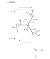
- FIG. 6 is a plan view showing an example of the flow of fluid flowing in the rotating device from the ⁇ X direction.
- the Y axis is the direction along the rotation axis 100
- the X axis and the Z axis are axes that intersect perpendicularly to the Y axis. 1 to 17, the same members will be described with the same numerals.
- the fluid means fresh water or seawater.
- the side of the rotating shaft 100 and the frame 130 in the direction of fluid flow may be referred to as the “downstream side”, and the side of the fluid flow direction may be referred to as the “upstream side”. ..
- the direction along the X axis may be referred to as “X direction”
- the direction along the Y axis may be referred to as “Y direction”
- the direction along the Z axis may be referred to as “Z direction”.
- the + side may be indicated by “+”
- the ⁇ side may be indicated by “ ⁇ ”.
- a section of the rectifying device which is sectioned by a plane including the X axis and the Z axis may be referred to as an “XZ section”.
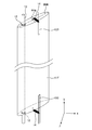
- FIG. 15 is a configuration diagram showing an example of the power generation device 1000.
- FIG. 16 is a perspective view showing an example of the rotating device 200 and the frame 130.
- FIG. 17 is a plan view showing an example of the flow of fluid flowing in the rotating device 200 from the ⁇ X direction.
- the rotating device 200 is a device that transmits a rotational force to the speed increasing gear 300 of the power generating device 1000 via the rotating shaft 100, for example.
- the speed increaser 300 is a device that increases the rotation speed of the rotating shaft 100 and transmits it to the generator 400.
- the power generation device 1000 is, for example, a hydroelectric power generation device including a tidal current power generation device.
- the tidal power generation device is a power generation device that generates electric power by rotating a water turbine using tidal energy generated by tidal power.
- a hydroelectric power generation device is a power generation device that converts kinetic energy of a water flow such as a tidal current into rotational energy to generate electric power.
- the rotating device 200 in which the rectifying device according to the present embodiment is arranged is, for example, the rotating device 200 of the vertical axis type power generating device 1000 such as the Darrieus type.
- the rotating device 200 includes a rotating shaft 100, an arm 110, and a blade 120.
- a rotating shaft 100 For example, one end of the rotary shaft 100 in the Y direction is connected to the speed increaser 300.
- the rotating shaft 100 transmits the rotational force to the speed increaser 300.
- the rotating shaft 100 rotates, for example, in a clockwise direction (hereinafter, referred to as “rotating direction”) when the blade 120 described below is viewed from the +Y direction.
- the arm 110 is a member that connects the rotating shaft 100 and the blade 120 to each other and transmits the lift in the rotating direction generated in the blade 120 to the rotating shaft 100.
- the arm 110 is, for example, radially extended from the rotary shaft 100, and the end portion on the opposite side of the rotary shaft 100 is connected to the blade 120.
- the blade 120 is a member that obtains a lift force in the rotation direction by the flow of fluid.
- the blade 120 rotates around the rotating shaft 100.
- the blade 120 transmits the lift force in the rotation direction via the arm 110 to the rotation shaft 100 as the rotation force in the rotation direction.
- the rotating device 200 is fixed to the frame 130 in water, for example.
- the frame 130 for example, one of the frame members 131 parallel to the rotating shaft 100 is fixed to a concrete structure such as a shore or a pier foundation.
- the frame 130 may be fixed on a foundation such as concrete installed on the sea floor, or may be fixed on a floating body installed on the sea surface.
- the frame 130 pivotally supports the rotating shaft 100 via bearings 140A and 140B so that the rotating shaft 100 can rotate.
- the rotating device 200 receives a flow of fluid.
- the fluid causes the blade 120 to lift. That is, since the rotating device 200 can obtain a larger lift by increasing the kinetic energy of the fluid reaching the blade 120, the power obtained from the fluid flow can be increased.
- the rectifying device according to the present embodiment is arranged so as to surround the rotating device 200 and collect the fluid in the rotating device 200.
- the rectifying device according to the present embodiment will be described in detail.
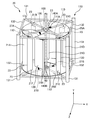
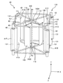
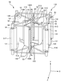
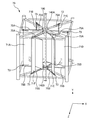
- FIG. 1 is a perspective view showing an example of a state in which the rectifying device 10 according to the first embodiment is arranged.
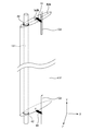
- FIG. 2 is a perspective view showing an enlarged example of the rectifying body 11F of the rectifying device 10 according to the first embodiment.
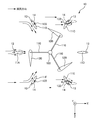
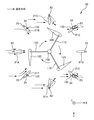
- FIG. 3A is a plan view seen from the +Y direction showing an example of a situation in which the rectifying device 10 according to the first embodiment rectifies the fluid flowing from the ⁇ X direction.
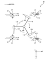
- FIG. 3B is a plan view seen from the +Y direction showing an example of a situation in which the rectifying device 10 according to the first embodiment rectifies the fluid flowing from the +X direction.
- the rectifying device 10 is a device that rectifies the fluid flowing from the upstream side toward the rotating device 200.
- the rectification by the rectification device 10 means, for example, changing the flow of the fluid in the direction toward the rotation shaft 100 so that the blade 120 of the rotation device 200 can efficiently generate a lift.
- the rectifier 10 includes rectifiers 11A to 11F, a bearing 12, a shaft support 13, a first rectifier spring 14, a first flat plate 15A, and a second flat plate 15B.
- the rectifying bodies 11A to 11F are members that rectify the fluid in the direction toward the rotating device 200. As shown in FIG. 1, the rectifying bodies 11A to 11F are composed of six pieces. The rectifying bodies 11A to 11F are arranged radially around the rotating shaft 100 so as to surround the rotating shaft 100. The rectifying bodies 11A to 11F are arranged so as not to contact the blade 120 of the rotating device 200. Further, the rectifying bodies 11A to 11F are arranged so as not to contact the frame 130 in the area surrounded by the frame 130.
- the rectifying bodies 11A to 11F are formed symmetrically with respect to the longest line segment passing through the center (hereinafter referred to as “long axis”) in the XY cross section when the XZ cross section is viewed from the +Y direction. In addition, in the XY cross section, they are formed symmetrically with the shortest line segment passing through the center (hereinafter, referred to as “short axis”) as a boundary. That is, the XY cross sections of the rectifying bodies 11A to 11F have a substantially elliptical shape. As a result, the rectifying bodies 11A to 11F can rectify the fluid toward the blades 120 and can suppress the turbulence and the vortex of the flow that may occur on the downstream side of the frame 130. Further, it is preferable that the rectifying bodies 11A to 11F are continuously formed along the Y direction and have at least the same length as the blade 120.
- the rectifying bodies 11A to 11F are made of, for example, a stainless material.
- the rectifying bodies 11A to 11F are arranged so that when the fluid is rectified toward the rotating shaft 100, for example, the extension line of the long axis intersects with the rotating shaft 100. More specifically, the rectifying bodies 11A and 11D are provided so as to face each other such that the direction along the flow of the fluid (X direction) and the long axis overlap with each other with the rotating shaft 100 interposed therebetween. There is. Further, the rectifying bodies 11B and 11F are provided at a predetermined angle with the rectifying body 11A in between, with the rotating shaft 100 as the center. In addition, the rectifying bodies 11C and 11E are provided at a predetermined angle with the rectifying body 11D as the center, with the rotating shaft 100 as the center. The predetermined angle is, for example, an acute angle.
- the rectifying bodies 11A to 11F are rotatably supported by, for example, a shaft support 13 described later through a bearing 12 described below. Accordingly, the rectifying bodies 11A to 11F can rotate when receiving a force from the fluid.
- the bearing 12 will be described in detail later.
- the rectifying bodies 11A to 11F are attached via the shaft support body 13 so as to be sandwiched by a first flat plate 15A and a second flat plate 15B, which will be described later, from the vertical direction (Y direction), for example.
- the rectifying bodies 11A to 11F are attached to the first flat plate 15A and the second flat plate 15B via the shaft support body 13, or are directly attached to the first flat plate 15A and the second flat plate 15B without the shaft support body 13. It may be attached to either.
- the first flat plate 15A, the second flat plate 15B, and the shaft support 13 will be described in detail later.
- the rectifying body 11F will be described as a representative as follows.
- the rectifying body 11F is connected to, for example, a first rectifying body spring 14 described later.
- the rectifying body 11F receives a force of fluid from one direction (-X direction)
- the side surface of the rectifying body 11F contacts the limiting plate 133, for example, so that the rectifying body 11F is restricted from rotating.
- the fluid flow direction ( ⁇ X direction) is resisted against the elastic bias of the first rectifying body spring 14.
- the first rectifying body spring 14 is also connected to at least the rectifying bodies 11B, 11C, and 11E.
- the limiting plate 133 is fixed to the frame 130.
- the first rectifying body spring 14 will be described in detail later. Further, the movements of the rectifying bodies 11A to 11F will also be described later in detail.
- the bearing 12 is provided between the shaft support 13 and the rectifying bodies 11A to 11F.
- the bearing 12 is a member that suppresses a rotational frictional force generated between the shaft support 13 and the rectifying bodies 11A to 11F. That is, the bearing 12 suppresses energy loss and heat generation that occur in the rectifying bodies 11A to 11F and the shaft support 13.
- the bearing 12 is a ball bearing made of, for example, a stainless material.
- the bearing 12 has, for example, at least one end (+Y end) and the other end ( ⁇ Y end) of the rectifiers 11A to 11F so that the rectifiers 11A to 11F can rotate without contacting the shaft support 13. It is provided in.
- the bearing 12 is preferably provided with, for example, a thrust collar in order to prevent the rectifying bodies 11A to 11F from moving in the axial direction (Y direction) of the shaft support body 13.
- the shaft support 13 is a member that supports the rectifying bodies 11A to 11F.
- the shaft support 13 is made of, for example, a stainless material and has a rod shape. As shown in FIG. 1, the shaft support 13 extends vertically from the circumferential portions of a first flat plate 15A and a second flat plate 15B, which will be described later, so as to connect them. Rectifiers 11A to 11F are axially supported on each of the shaft support bodies 13 from one end (+Y end) to the other end ( ⁇ Y end). As a result, the rectifying bodies 11A to 11F can rectify the fluid from the circumferential portions of the first flat plate 15A and the second flat plate 15B toward the rotary shaft 100.
- the first rectifying body spring 14 is a member that applies an elastic force to the rectifying bodies 11B, 11C, 11E, and 11F.
- the first rectifying body spring 14 is made of, for example, a stainless material.
- the first rectifying body spring 14 has one end connected to the rectifying body 11F and the other end connected to the limiting plate 133.
- the first rectifying body spring 14 applies an elastic force to the rectifying body 11F in a direction toward the limiting plate 133.
- the limiting plate 133 is a member that limits the rotation range of the rectifying body 11F.
- the first rectifying body spring 14 is similarly connected to the rectifying bodies 11B, 11C, and 11E.
- the rectifying bodies 11B and 11F rotate according to the elastic force of the first rectifying body spring 14.
- the downstream side (+X direction side) of the rectifying bodies 11B and 11F contacts the limiting plate 133.
- the rectifying bodies 11B and 11F are restricted from rotating in the direction of the fluid flow, and can be rectified so that the fluid flow is directed to the rotating shaft 100.
- the limiting plate 133 is provided on the downstream side (+X direction side) of the rectifying bodies 11B and 11F, and the rectifying bodies 11B and 11F rotate according to the elastic force of the first rectifying body spring 14. When it does, the rotation is restricted.
- the rectifying bodies 11C and 11E rotate against the elastic force of the first rectifying body spring 14 so that their major axes follow the flow of the fluid. Thereby, the rectifying bodies 11C and 11E can suppress the resistance of the fluid flow. Then, the rectifying bodies 11C and 11E return to their original positions according to the elastic force of the first rectifying body spring 14 when the flow of the fluid is stopped.
- the rectifying bodies 11C and 11E rotate according to the elastic force of the first rectifying body spring 14.
- the downstream side ( ⁇ X direction side) of the rectifying bodies 11C and 11E contacts the limiting plate 133.
- the rectifying bodies 11C and 11E are restricted from rotating in the direction of the fluid flow, and can be rectified so that the fluid flow is directed to the rotation shaft 100.
- the limiting plate 133 is provided on the downstream side ( ⁇ X direction side) of the rectifying bodies 11C and 11E, and the rectifying bodies 11C and 11E rotate according to the elastic force of the first rectifying body spring 14. When moving, it limits its rotation.
- the rectifying bodies 11B and 11F rotate against the elastic force of the first rectifying body spring 14 so that their long axes follow the flow of the fluid. As a result, the rectifying bodies 11B and 11F can suppress the resistance of the fluid flow. Then, the rectifying bodies 11B and 11F return to their original positions according to the elastic force of the first rectifying body spring 14 when the flow of the fluid is stopped.
- the first rectifying body spring 14 faces the limiting plate 133 with respect to any of the rectifying bodies 11B, 11C, 11E, and 11F arranged on the upstream side of the rotating shaft 100 in the fluid flow direction. It is a member that applies an elastic force to any of the rectifying bodies 11B, 11C, 11E, and 11F arranged on the downstream side in the direction opposite to the rotating direction.
- the rectifying bodies 11A, 11B, and 11F are provided, and the rectifying bodies 11C, 11D, and 11E include Flow resistance occurs.
- the rectifying bodies 11C, 11D, and 11E are provided, and the rectifying bodies 11A, 11B, and 11F include the fluid Flow resistance occurs. Therefore, at least the rectifying bodies 11B, 11C, 11E, 11F are provided with the first rectifying body spring 14 so as to rotate against the elastic force in order to suppress the resistance due to the tidal current in the X direction. Need to be
- the first flat plate 15A and the second flat plate 15B are members for holding the rectifying bodies 11A to 11F in the region surrounded by the frame 130.
- the first flat plate 15A and the second flat plate 15B are made of, for example, a stainless material and have a disc shape.
- the first flat plate 15A is axially supported by the bearing 140A on the +Y direction side.
- the second flat plate 15B is axially supported by the bearing 140B on the ⁇ Y direction side.
- the shaft support 13 is provided in the circumferential portion.
- the plane of the first flat plate 15A and the plane of the second flat plate 15B are arranged to face each other in the Y direction. That is, the first flat plate 15A and the second flat plate 15B are connected to each other by the shaft support 13.
- the first flat plate 15A and the second flat plate 15B are arranged in a region surrounded by the frame 130. Accordingly, when the flow straightening plates 11A to 11F are attached, they can be arranged without being affected by the structure of the frame 130.
- the first flat plate 15A and the second flat plate 15B have been described as being supported by the bearings 140A and 140B, they may be fixed to the frame 130, and the supporting method thereof is not limited.
- the first flat plate 15A and the second flat plate 15B may include bearings (not shown) and flat plate springs 16A and 16B. As a result, the first flat plate 15A and the second flat plate 15B can rotate about the rotation shaft 100 according to the flow of the fluid.
- One end of each of the flat plate springs 16A and 16B is connected to the first flat plate 15A and the second flat plate 15B, and the other end is connected to the frame 130.
- the flat plate springs 16A and 16B are members that give elastic force to the first flat plate 15A and the second flat plate 15B.
- the flat plate spring 16A is elastically biased, for example, in the counterclockwise direction when viewed from the +Y direction.
- the flat plate spring 16B is elastically biased clockwise, for example, when viewed from the +Y direction. That is, when the first flat plate 15B rotates counterclockwise, the elastic force in the clockwise direction acts to try to return it to the original position.
- the rotation range of the first flat plate 15A and the second flat plate 15B is limited regardless of the direction in which the rectifying bodies 11A to 11F receive the force of the fluid flow.
- FIG. 3A is a plan view seen from the +Y direction showing an example of a situation in which the rectifying device 10 according to the first embodiment rectifies the fluid flowing from the ⁇ X direction.
- FIG. 3B is a plan view seen from the +Y direction showing an example of a situation in which the rectifying device 10 according to the first embodiment rectifies the fluid flowing from the +X direction.
- the rectifiers 11B, 11A, 11F rectify the fluid toward the rotary shaft 100 on the upstream side of the rotary shaft 100.
- the rectifying bodies 11C, 11D, 11E rotate along the flow of the fluid so as not to generate resistance with the fluid.
- the major axis of the rectifying body 11A is the direction of the flow of the fluid (hereinafter, referred to as “tide direction”) so as to suppress the turbulence of the fluid and the generation of vortices such as Karman vortices. Rotate along.
- the rectifying bodies 11B and 11F rectify, on the upstream side of the rotating shaft 100, the fluid that should not hit the blade 120 in the direction toward the rotating shaft 100. At this time, the rectifiers 11B and 11F are restricted from rotating in the direction of fluid flow because the downstream side surface (+X direction side) is in contact with the restriction plate 133.
- the extension lines of the long axes of the rectifying bodies 11B and 11F and the rotating shaft 100 are maintained so as to intersect with each other. Further, the rectifying bodies 11C and 11E rotate against the elastic force of the first rectifying body spring 14 so as not to generate resistance with the fluid. In that state, since the elastic force is applied to the rectifying bodies 11C and 11E on the side opposite to the rotating direction, when the flow of the fluid is stopped, it returns to the original state according to the elastic force.
- the rectifying bodies 11C, 11D, and 11E rectify the fluid toward the rotating shaft 100 on the upstream side of the rotating shaft 100.
- the rectifying bodies 11B, 11A, 11F rotate so as not to generate resistance with the fluid.
- the rectifying body 11A to 11F in the movement of the rectifying body shown in FIG. 3A, the rectifying body 11A is replaced with the rectifying body 11D, and the rectifying bodies 11B and 11F are replaced with rectifying bodies 11C and 11E. Since it is equivalent to replacing the rectifying bodies 11C and 11E with the rectifying bodies 11B and 11F, the description thereof will be omitted.
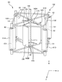
- FIG. 4 is a perspective view showing an example of a state in which the rectifying device 20 according to the second embodiment is arranged.
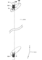
- FIG. 5 is a perspective view showing an enlarged example of the rectifying body 21H of the rectifying device 20 according to the second embodiment.
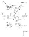
- FIG. 6A is a plan view seen from the +Y direction showing an example of a situation in which the rectifying device 20 according to the second embodiment rectifies the fluid flowing from the ⁇ X direction.
- FIG. 6B is a plan view seen from the +Y direction showing an example of a situation in which the rectifying device 20 according to the second embodiment rectifies the fluid flowing from the +X direction.
- the rectifying device 20 includes rectifying bodies 21A to 21H, a bearing 22, a shaft support 23, a first rectifying body spring 24, a first flat plate 25A, a second flat plate 25B, and a second flat plate 25B.
- Rectifier springs 26A and 26B are included.
- the flat plate springs 27A and 27B the rectifying bodies 11A to 11F of the rectifying device 10 according to the first embodiment, the bearing 12, the shaft support 13, the first rectifying body spring 14, and the first flat plate 15A.
- the rectifying bodies 21A to 21H are members that rectify the fluid in the direction toward the rotating device 200.
- the rectifying bodies 21A to 21H are composed of eight.
- the rectifying bodies 21A to 21H are arranged so as not to contact the blade 120 of the rotating device 200.
- the rectifying bodies 21A to 21H are arranged radially around the rotating shaft 100 so as to surround the rotating shaft 100. Further, the rectifying bodies 21A to 21H are arranged so as not to contact the frame 130 in the area surrounded by the frame 130.
- the rectifying bodies 21A to 21H are arranged so that, for example, when the fluid is rectified toward the rotating shaft 100, the extension line of the long axis intersects with the rotating shaft 100.
- the rectifying bodies 21A and 21D are provided so as to face each other such that the direction along the flow of the fluid (X direction) and the long axis overlap with each other with the rotating shaft 100 interposed therebetween.
- the rectifying bodies 21B and 21F are provided at a predetermined angle with the rectifying body 21A in between, with the rotation shaft 100 as the center.
- the rectifying bodies 21C and 21E are provided at a predetermined angle with the rectifying body 21D in between, with the rotating shaft 100 as the center.
- the predetermined angle is an acute angle.
- the rectifying bodies 21G and 21H are arranged such that the major axis thereof overlaps with the Z direction in the state where there is no fluid flow. That is, the rectifying bodies 21G and 21H are arranged so that the long axes thereof intersect perpendicularly to the tidal current direction so as to receive the fluid flow most strongly.
- second rectifying body springs 26A and 26B which will be described later, are connected to the rectifying body 21H, for example.
- the rectifying body 21H rotates against the flow of the fluid in the X direction against the elastic force of the second rectifying body springs 26A and 26B.
- the second rectifying body springs 26A and 26B will be described later in detail.
- the movements of the rectifying bodies 21A to 21H will also be described later in detail.
- the second rectifying body springs 26A and 26B are members that apply elastic force to the rectifying bodies 21G and 21H. By applying the elastic force, rotation of the rectifying bodies 21G and 21H is restricted with respect to the flow in the X direction.
- the second rectifying body springs 26A and 26B are made of, for example, a stainless material.
- the second rectifying body springs 26A and 26B have one end connected to the rectifying body 21H and the other end connected to the shaft support 23.
- the second rectifying body spring 26A gives an elastic force in the +X direction, for example.
- the second rectifying body spring 26B gives an elastic force in the ⁇ X direction, for example. That is, the second rectifying body spring 26A and the second rectifying body spring 26B give elastic forces in opposite directions. In other words, the rectifying body 21H rotates against the elastic force with respect to both the tidal current flowing from the +X direction to the ⁇ X direction and the tidal current flowing from the ⁇ X direction to the +X direction.
- the second rectifying body springs 26A and 26B incline the rectifying body 21H toward the X direction by a predetermined angle when receiving the fluid flow.
- the predetermined angle means, for example, 45 degrees.
- the second rectifying body springs 26A and 26B are similarly connected to the rectifying body 21G.
- FIG. 6A is a plan view seen from the +Y direction showing an example of a situation in which the rectifying device 20 according to the second embodiment rectifies the fluid flowing from the ⁇ X direction.
- FIG. 6B is a plan view seen from the +Y direction showing an example of a situation in which the rectifying device 20 according to the second embodiment rectifies the fluid flowing from the +X direction.
- the rectifying bodies 21A to 21H rectify the fluid toward the rotating shaft 100 on the upstream side of the rotating shaft 100 and rotate. On the downstream side of the shaft 100, the shaft 100 rotates so that resistance does not occur between the fluid and the rectifying body.
- the rectifier 21A has a major axis that rotates along the tide direction so as to suppress turbulence of the fluid flow and generation of vortices such as Karman vortices.
- the rectifying bodies 21B and 21F rectify the fluid, which originally should not correspond to the blade 120 and passes downstream, on the upstream side of the rotating shaft 100 in the direction toward the rotating shaft 100.
- the rectifying bodies 21B and 21F are restricted from rotating in the counterclockwise direction about the pivotal support body 23 because the side surface on the downstream side (+X direction side) contacts the limiting plate 133.
- the extended lines of the long axes of the rectifying bodies 21B and 21F and the rotating shaft 100 are maintained so as to intersect with each other.
- the rectifying bodies 21G and 21H rectify the fluid passing through the downstream side instead of the blade 120 in the direction toward the blade 120 at the boundary between the upstream side and the downstream side of the rotating shaft 100.
- the rectifying bodies 21G and 21H rotate against the elastic force of the second rectifying body springs 26A and 26B, and are maintained at a predetermined angle with respect to the tidal current direction.
- the rectifying bodies 21C and 21E rotate against the elastic force of the first rectifying body spring so as not to generate resistance with the fluid. In that state, since the elastic force is applied to the rectifying bodies 21C and 21E on the side opposite to the rotating direction, when the flow of the fluid is stopped, the rectifying bodies 21C and 21E return to the original state according to the elastic force.
- the rectifying bodies 21A to 21H when the fluid is flowing from the +X direction to the ⁇ X direction, the rectifying bodies 21A to 21H rectify the fluid toward the rotating shaft 100 on the upstream side of the rotating shaft 100 and rotate. On the downstream side of the shaft 100, the shaft 100 rotates so that resistance does not occur between the fluid and the rectifying body.
- the rectifying body 21A is replaced with the rectifying body 21D in the movement of the rectifying bodies 21A to 21H shown in FIG. 6A, and the rectifying bodies 21B and 21F are changed to the rectifying bodies 21C and 21E. Is the same as replacing the rectifying bodies 21C and 21E with the rectifying bodies 21B and 21F, and the description thereof will be omitted.
- the rectifying bodies 21G and 21H move in the same manner as the fluid shown in FIG. 6A.
- FIG. 7 is a perspective view showing an example of a state in which the rectifying device 30 according to the third embodiment is arranged.
- FIG. 8A is a plan view seen from the +Y direction showing an example of a situation in which the rectifying device 30 according to the third embodiment rectifies the fluid flowing from the ⁇ X direction.
- FIG. 8B is a plan view seen from the +Y direction showing an example of a situation in which the rectifying device 30 according to the third embodiment rectifies the fluid flowing from the +X direction.
- the rectifying device 30 according to the third embodiment includes rectifying bodies 31A to 31D, a bearing 32, a shaft support 33, a first rectifying body spring 34, a first flat plate 35A, and a second flat plate 35B. It is configured.
- the rectifying bodies 31A to 31D are members that rectify the fluid in the direction toward the rotating device 200.
- the rectifying bodies 31A to 31D are composed of four.
- the rectifying bodies 31A to 31D are arranged so as not to contact the blade 120 of the rotating device 200.
- the rectifying bodies 31A to 31D are radially arranged around the rotating shaft 100 so as to surround the rotating shaft 100. Further, the rectifying bodies 31A to 31D are arranged so as not to contact the frame 130 in the area surrounded by the frame 130.
- the rectifying bodies 31A to 31D are arranged so that, for example, when the fluid is rectified toward the rotating shaft 100, the extension line of the long axis intersects with the rotating shaft 100.
- the rectifying bodies 31A to 31D may be rotatably supported by the shaft support 33, or may be fixed by being sandwiched between the first flat plate 35A and the second flat plate 35B from the vertical direction (Y direction). Good.
- FIG. 8A is a plan view seen from the +Y direction showing an example of a situation in which the rectifying device 30 according to the third embodiment rectifies the fluid flowing from the ⁇ X direction.
- FIG. 8B is a plan view seen from the +Y direction showing an example of a situation in which the rectifying device 30 according to the third embodiment rectifies the fluid flowing from the +X direction.
- the rectifying bodies 31A to 31D rectify the fluid toward the rotating shaft 100 on the upstream side of the rotating shaft 100, and rotate. On the downstream side of the shaft 100, the fluid and the rectifying bodies 31A to 31D are rotated so as not to generate resistance.
- the rectifying bodies 31A and 31B rectify the fluid passing through the upstream side of the rotating shaft 100, which would normally not correspond to the blade 120 but toward the downstream side, toward the rotating shaft 100.
- the rectifying bodies 31A and 31B are restricted from rotating in the counterclockwise direction around the pivotal support body 33 because the downstream side surface (on the +X direction side) contacts the limiting plate 133.
- the extension lines of the long axes of the rectifying bodies 31A and 31B are maintained so as to intersect with the rotating shaft 100.
- the rectifying bodies 31C and 31D rotate against the elastic force of the first rectifying body spring 34 so as not to generate resistance with the fluid. In that state, since the elastic force is applied to the rectifying bodies 31C and 31D on the side opposite to the rotating direction, when the flow of the fluid is stopped, the rectifying bodies 31C and 31D return to the original state according to the elastic force.
- the rectifying bodies 31A to 31D when the fluid is flowing from the +X direction to the ⁇ X direction, the rectifying bodies 31A to 31D rectify the fluid toward the rotating shaft 100 on the upstream side of the rotating shaft 100 and rotate. On the downstream side of the shaft 100, the shaft 100 rotates so that resistance does not occur between the fluid and the rectifying body.
- the rectifying body 31A to 31D in the movement of the rectifying bodies 31A to 31D shown in FIG. 8A, the rectifying body 31A is replaced with the rectifying body 31C, and the rectifying body 31B is replaced with the rectifying body 31D. Since the fluid 31C is replaced with the rectifying body 31A and the rectifying body 31D is replaced with the rectifying body 31B, the description thereof will be omitted.
- FIG. 9 is a perspective view showing an example of a state in which the rectifying device 40 according to the fourth embodiment is arranged.
- FIG. 10 is a perspective view showing an enlarged example of the rectifying body of the rectifying device 40 according to the fourth embodiment.
- the rectification device 40 is a device that is arranged in the frame member 131 and the shaft support 43 to rectify the fluid.
- the rectifying device 40 includes rectifying bodies 41A to 41F, a bearing 42, a shaft support 43, and a first frame spring 44.
- the rectifying bodies 41A to 41F are members that rectify the fluid in the direction toward the rotating device 200. As shown in FIG. 9, the rectifying bodies 41A to 41F are provided between the rectifying bodies 41B, 41C, 41E, and 41F that are axially supported by the frame member 131 and the shaft supporting body 43 that is provided between the adjacent frame members 131. The rectifying bodies 41A and 41D are supported. The rectifying bodies 41A and 41D are arranged at equal distances from the adjacent frame members 131 in the Z direction. The rectifying bodies 41A to 41F are arranged so that, for example, when the fluid is rectified toward the rotating shaft 100, the extension line of the long axis intersects with the rotating shaft 100.
- the rectifying bodies 41A to 41F are formed symmetrically with respect to the longest long axis passing through the center in the XY cross section when the XZ cross section is viewed from the +Y direction. In addition, it is formed symmetrically within the XY section with the shortest short axis passing through the center as a boundary. That is, the XY cross sections of the flow control bodies 41A to 41F have a substantially elliptical shape. As a result, the rectifying bodies 41A to 41F can rectify the fluid toward the blade 120 while suppressing the turbulence and vortex of the flow that may occur on the downstream side of the frame 130.
- the rectifying bodies 41A to 41F are continuously formed along the Y direction and have at least the same length as the blade 120.
- the rectifying bodies 41A to 41F have a major axis length that does not contact the blade 120.
- the rectifying bodies 41A to 41F are made of, for example, a stainless material.
- the rectifying bodies 41A and 41D are rotatably supported by, for example, a shaft support body 43 described later via a bearing 42.
- the rectifying bodies 41B, 41C, 41E, 41F are rotatably supported by the frame member 131 via bearings 42. Accordingly, the rectifying bodies 41A to 41F can rotate when receiving a force from the fluid.
- the shaft support 43 will be described in detail later.
- the rectifier 41F will be described below as a representative.
- the rectifying body 41F is connected to, for example, a first frame spring 44 described later.
- the rectifying body 41F receives a fluid force from one direction (-X direction)
- the side surface of the rectifying body 41F contacts the limiting plate 133, for example, so that the rectifying body 41F is prevented from rotating.
- the fluid flow direction ( ⁇ X direction) is resisted against the elastic bias of the first rectifying body spring 44.
- the first frame spring 44 is similarly connected to at least the rectifying bodies 41B, 41C, and 41E. The movements of the rectifying bodies 41A to 41F will be described later in detail.
- the shaft support 43 is a member that supports the rectifying bodies 41A and 41D.
- the shaft support 43 is made of, for example, a stainless material and has a rod shape. As shown in FIG. 9, the shaft support 43 is provided so as to connect two frame members 132, which connect adjacent frame members 131 and extend in the Z direction, in the Y direction. Rectifiers 41A and 41D are axially supported by the respective shaft support members 43 from one end (+Y end) to the other end ( ⁇ Y end).
- the first frame spring 44 is a member that applies an elastic force to the rectifying bodies 41B, 41C, 41E, 41F.
- the first frame spring 44 is made of, for example, a stainless material.
- the first frame spring 44 has one end connected to the rectifying body 41F and the other end connected to the limiting plate 133.
- the first frame spring 44 applies an elastic force to the rectifying body 41F in the direction toward the limiting plate 133.
- the limiting plate 133 is a member that limits the rotation range of the rectifying body 41F.
- the first frame spring 44 is similarly connected to the rectifying bodies 41B, 41C, 41E.
- the rectifying bodies 41B and 41F rotate according to the elastic force of the first frame spring 44.
- the downstream side (+X direction side) of the rectifying bodies 41B and 41F contacts the limiting plate 133.
- the rectifying bodies 41B and 41F are restricted from rotating in the direction of the fluid flow, and can be rectified so that the fluid flow is directed to the rotating shaft 100.
- the limiting plate 133 is provided on the downstream side (+X direction side) of the rectifying bodies 41B and 41F, and the rectifying bodies 41B and 41F rotate according to the elastic force of the first frame spring 44. Sometimes, that rotation is limited.
- the rectifying bodies 41C and 41E rotate against the elastic force of the first frame spring 44 so that their major axes follow the flow of the fluid. Thereby, the rectifying bodies 41C and 41E can suppress the resistance of the fluid flow. Then, the rectifying bodies 41C and 41E return to their original positions according to the elastic force of the first frame spring 44 when the flow of the fluid is stopped.
- the rectifying bodies 41C and 41E rotate according to the elastic force of the first frame spring 44.
- the side faces of the rectifying bodies 41C and 41E on the downstream side ( ⁇ X direction side) contact the limiting plate 133.
- the rectifiers 41C and 41E are restricted from rotating in the direction of the fluid flow, and can be rectified so that the fluid flow is directed to the rotation shaft 100. That is, the limiting plate 133 is provided on the downstream side ( ⁇ X direction side) of the rectifying bodies 41C and 41E, and the rectifying bodies 41C and 41E rotate according to the elastic force of the first frame spring 44. When it does, the rotation is restricted.
- the rectifying bodies 41B and 41F rotate against the elastic force of the first frame spring 44 so that their major axes follow the flow of the fluid. As a result, the rectifying bodies 41B and 41F can suppress the resistance of the fluid flow. Then, the rectifying bodies 41B and 41F return to their original positions according to the elastic force of the first frame spring 44 when the flow of the fluid is stopped.
- the first frame spring 44 is elastic toward the limiting plate 133 with respect to any of the rectifying bodies 41B, 41C, 41E, 41F arranged on the upstream side of the rotary shaft 100 in the direction of fluid flow. It is a member that applies a force and applies an elastic force to any of the rectifying bodies 41B, 41C, 41E, and 41F arranged on the downstream side in a direction opposite to the rotating direction.
- FIG. 11 is a perspective view showing an example of a state in which the rectifying device 50 according to the fifth embodiment is arranged.
- FIG. 12 is a perspective view showing an enlarged example of the rectifying body 51H of the rectifying device 50 according to the fifth embodiment.
- the rectifying device 50 according to the fifth embodiment includes rectifying bodies 51A to 51H, a bearing 52, a shaft support 53, a first frame spring 54, and second frame springs 55A and 55B. There is.
- the rectifying bodies 51A to 51F, the bearing 52, the shaft support 53, and the first frame spring 54 of the rectifying device 50 according to the fifth embodiment the rectifying device 40 according to the fourth embodiment is adjusted. Since each of the fluids 41A to 41F, the bearing 42, the shaft support 43, and the first frame spring 44 has the same structure, description thereof will be omitted.
- the rectifying bodies 51G and 51H of the rectifying device 50 according to the fifth embodiment and the second frame springs 55A and 55B the rectifying bodies 21G and 21H of the rectifying device 20 according to the second embodiment and the Since it has the same structure as the two rectifying body springs 26A and 26B, description thereof will be omitted. Therefore, in the following description, only differences from the rectifying device 40 according to the fourth embodiment and the rectifying device 20 according to the second embodiment will be described, and matters not described will be described with respect to the rectifying device according to the fourth embodiment. 40 and the same rectification device 20 according to the second embodiment.
- the rectifying bodies 51A to 51H are members that rectify the fluid in the direction toward the rotating device 200.
- the rectifying bodies 51A to 51H are composed of eight.
- the rectifying bodies 51G and 51H are rotatably supported by, for example, a shaft support body 53 via a bearing 52.
- the rectifying bodies 51G and 51H are arranged at equal distances from the frame members 131 adjacent to each other in the Z direction.
- the rectifying bodies 51G and 51H are arranged such that the major axis thereof overlaps with the Z direction in the state where there is no fluid flow. That is, the rectifying bodies 51G and 51H are arranged such that the major axes thereof intersect perpendicularly to the tidal current direction so that a large amount of fluid flow can be received.
- the second rectifying body springs 55A and 55B are members that apply elastic force to the rectifying bodies 51G and 51H. By applying the elastic force, rotation of the rectifying bodies 51G and 51H is restricted with respect to the flow in the X direction.
- the second rectifying body springs 55A and 55B are made of, for example, a stainless material.
- the second rectifying body springs 55A and 55B have one end connected to the rectifying body 51H and the other end connected to the shaft support 53.
- the second rectifying body spring 55A gives an elastic force in the +X direction, for example.
- the second rectifying body spring 55B gives an elastic force in the ⁇ X direction, for example. That is, the second rectifying body spring 55A and the second rectifying body spring 55B apply elastic force in opposite directions. In other words, the rectifying body 21H rotates against the elastic force with respect to both the tidal current flowing from the +X direction to the ⁇ X direction and the tidal current flowing from the ⁇ X direction to the +X direction.
- the second rectifying body springs 55A and 55B incline the rectifying body 51H to the X direction side by a predetermined angle when receiving the flow of the fluid, and the predetermined angle means, for example, 45 degrees.
- the second rectifying body springs 55A and 55B are similarly connected to the rectifying body 51G.
- FIG. 13 is a perspective view showing an example of a state in which the rectifying device 60 according to the sixth embodiment is arranged.
- the rectifying device 60 according to the sixth embodiment includes rectifying bodies 61A to 61D, a bearing 62, and a first frame spring 63.
- the rectifying bodies 61A to 61D of the rectifying device 60 according to the sixth embodiment the bearing 62, and the spring 63 for the first frame
- 41E, the bearing 42, and the first frame spring 44 have the same structure, and thus the description thereof will be omitted. Therefore, in the following description, only differences from the rectifying device 40 according to the fourth embodiment will be described, and matters not described are the same as those of the rectifying device 40 according to the fourth embodiment.
- the rectifying bodies 61A to 61D are members that rectify the fluid in the direction toward the rotating device 200.
- the rectifying bodies 61A to 61D are composed of four.
- the rectifying bodies 61A to 61D are arranged so that, for example, when the fluid is rectified toward the rotating shaft 100, the extension line of the long axis intersects with the rotating shaft 100.
- the rectifying bodies 61A to 61D are rotatably supported by the frame member 131 via bearings 62. Accordingly, the rectifying bodies 61A to 61D can rotate when receiving a force from the fluid.
- the rectifying bodies 11A to 11F, 21A to 21H, 31A to 31D, 41A to 41F, 51A to 51H, and 61A to 61D have been described as having a substantially elliptical XZ section, but the present invention is not limited to this.
- a flat plate may be extended from the shaft support 13, 23, 33, 43, 53 or the frame member 131. Further, it may have a triangular shape whose width becomes narrower in the direction of rectification from the axis of the shaft support 13, 23, 33, 43, 53 or the frame member 131.
- the rectifiers 10 to 60 have been described as including the bearings 12, 22, 32, 42, 52, 62, but the invention is not limited thereto.
- the rectifiers 10 to 60 may not be provided with the bearings 12, 22, 32, 42, 52, 62, and the rectifiers (11A to 11F, 21A to 21H, 31A to 31D, 41A to 41F, 51A to 51H, 61A to 61D) at the +Y direction end and the ⁇ Y direction end so that they can be rotated with respect to the shaft support 13, 23, 33, 43, 53 or the frame member 131 so as not to move in the Y direction. Should be provided in.
- the rectifying devices 10, 20, 30 are described as including the first rectifying body springs 14, 24, 34, but are not limited thereto.
- the first rectifying body springs 14, 24, 34 may not be provided.
- a rectifying body (11A to 11F, 21A to 21H, 31A to 31D) is provided with such a movement is restricted when trying to rotate. May be.
- a rod-shaped restricting body (not shown) contacting a side surface opposite to the side surface contacting the restricting plate 133 is a predetermined part of the frame 130. It may be suspended from the location.
- the rectifying device 20 is described as including the second rectifying body springs 26A and 26B, but the present invention is not limited to this.
- the second rectifying body springs 26A and 26B may not be provided.
- a spring may be provided that restricts movement when the rectifying bodies 21G and 21H are about to rotate in the X direction.
- a rod-shaped limiting body (not shown) that abuts the side surface on the side where rotation is desired to be limited is suspended from the frame 130 in the state where there is no fluid flow. Good.
- the rectifying device is described as including and including the shaft supports 13, 23, 33, but the present invention is not limited to this.
- the shaft supports 13, 23, 33 may not be provided, and the first flat plates 15A, 25A, 35A and the second flat plates 15B, 25B, 35B may be used as the rectifying bodies (11A to 11F, 21A to 21H, 31A to 31D). ) May be sandwiched and fixed in the vertical direction (Y direction).
- the rectification devices 40, 50, 60 are described as including the first frame springs 44, 54, 63, but the present invention is not limited to this.
- the first frame springs 44, 54, 63 may not be provided. Instead of the first frame springs 44, 54, 63, for example, the movement is restricted when the rectifying body (41A to 41F, 51A to 51H, 61A to 61D) tries to rotate in one direction. May be provided.
- a rod-shaped restricting body (not shown) contacting a side surface opposite to the side surface contacting the restricting plate 133 is a predetermined part of the frame 130. It may be suspended from the location.
- the rectifying device 50 is described as including the second frame springs 55A and 55B, but the present invention is not limited to this.
- the second frame springs 55A and 55B may not be provided.
- a device that restricts the movement when the rectifying bodies 51G and 51H try to rotate in the X direction may be provided. Specifically, in a state in which there is no fluid flow, a rod-shaped restricting body (not shown) that abuts the side surface on the side where rotation is desired to be restricted is hung from the frame 130 in the rectifying bodies 51G and 51H. Good.
- the rectifiers 10 to 30 are described as including the first flat plates 15A, 25A, 35A and the second flat plates 15B, 25B, 35B, but the present invention is not limited thereto.
- the first flat plates 15A, 25A, 35A and the second flat plates 15B, 25B, 35B may not be provided.
- the shaft supporting bodies 13, 23, 33 may be connected to the frame 130 to support the rectifying bodies (11A to 11F, 21A to 21H, 31A to 31D).
- first flat plates 15A, 25A, 35A and the second flat plates 15B, 25B, 35B have been described as having a disc shape (flat plate shape), but the present invention is not limited to this.
- it may be a first frame member 75A and a second frame member 75B that extend radially around the rotation shaft 100 and have a rod shape, for example.
- the first and second frame members 75A and 75B support the respective rectifying bodies 71A to 71F so as to sandwich them from the vertical direction (Y direction).
- the rectifying bodies 71A to 71F are attached to the first and second frame members 75A and 75B via the shaft support body 73.
- first and second frame members 75A and 75B may be made of an elastic material.
- first and second frame members 75A and 75B that support the rectifying bodies 71B and 71F will be described.
- the first and second frame members 75A and 75B supporting the rectifying bodies 71B and 71F face the Z axis with the rotator 100 as the center along the XZ plane. To bend. Thereby, the flow of the fluid can be collected in the rotating device 200 while suppressing the resistance received from the running water.
- the rectifying devices 10 to 60 are in contact with the blade 120 in the rotating device 200 that has the blade 120 that is attached to the rotating shaft 100 and receives the flow of the fluid to rotate the rotating shaft 100.
- Rectifiers (11A to 11F, 21A to 21H, 31A to 31D, 41A) that are provided so as to surround the rotating device 200 and rectify the flow of fluid in the direction surrounding the rotating device 200 in the direction toward the rotating device 200.
- 41F 51A to 51H, 61A to 61D.
- the flow of fluid can be collected in the rotating device 200, so that the amount of power generation can be increased.
- the first flat plates 15A, 25A and 35A and the rectifying bodies are composed of the first flat plates 15A, 25A and 35A. It further comprises second flat plates 15B, 25B, 35B sandwiched and held. According to the present embodiment, the rectifying devices 10 to 30 can be arranged regardless of the structure of the frame 130, so that the manufacturing cost can be reduced.
- the rectifying bodies (11A to 11F, 21A to 21H, 31A) are provided between the first flat plates 15A, 25A, 35A and the second flat plates 15B, 25B, 35B.
- the shaft support members 13, 23, 33 that pivotally support the rectifying members (11A to 11F, 21A to 21H, 31A to 31D) are further provided so that the (.about.31D) rotate according to the flow of the fluid.
- the flow of the fluid can be collected by coping with the change in the flow of the fluid, so that the amount of generated electric power can be increased.
- a first frame member 75A and a second frame member 75B that holds the rectifying bodies 71A to 71F by sandwiching them between the first frame member 75A, Is further provided.
- the cost required for the material can be significantly reduced.
- the rectifying bodies 71A to 71F are provided between the first frame member 75A and the second frame member 75B and rotate according to the flow of water. And a shaft support 73 that supports the rectifying bodies 71A to 71F so as to move.
- the rectifying device 70 can be arranged regardless of the structure of the frame 130, so that the manufacturing cost can be reduced.
- the rectifiers (11A to 11F, 21A to 21H, 31A to 31D) rectify the flow of the fluid in the direction toward the rotating device 200.
- the rectifying bodies (11A to 11F, 21A to 21H, 31A to 31D) can be inclined so as to efficiently collect the flow of fluid, it is possible to increase the amount of generated power.
- the first flat plate 15A is configured so that the rectifying bodies (11A to 11F, 21A to 21H, 31A to 31D) rectify the fluid flow in the direction toward the rotating device 200.
- the first flat plates 15A, 25A, 35A and the second flat plates 15B, 25B, 35B can be rotated so that the flow of the fluid can be efficiently collected, the amount of generated power increases. Can be achieved.
- the first frame member 75A and the second frame member 75B flow the fluid so that the rectifying bodies 71A to 71F rectify the flow of the fluid in the direction toward the rotating device 200. It is made of an elastic material that deforms depending on the direction. According to the present embodiment, the first frame member 75A and the second frame member 75 can be elastically deformed so that the flow of the fluid can be efficiently collected, so that the amount of generated electric power can be increased.
- the rectifiers (11A to 11F, 21A) are rotated so that the rectifiers (11A to 11F, 21A to 21H, 31A to 31D) rotate along the flow of the fluid. ⁇ 21H, 31A to 31D) and the bearings 12, 22, 32 provided between the shaft supports 13, 23, 33. According to the present embodiment, the rectifying bodies (11A to 11F, 21A to 21H, 31A to 31D) can be smoothly rotated, so that the fluid flow can be efficiently collected.
- the rectifying bodies (41A to 41F, 51A to 51H, 61A to 61D) surround the rotating device 200 and configure the frame 130 for fixing the rotating device 200 in water.
- the frame member 131 provided in parallel with the rotating shaft 100 is pivotally supported. According to this embodiment, the cost can be reduced because it can be installed on the existing frame member 131.
- the rectifiers 40 to 60 rectify the flow of the fluid in the direction toward the rotating device 200.
- the rectifiers (41A to 41F, 51A to 51H, 61A to 61D) rectify the flow of the fluid in the direction toward the rotating device 200.
- the rectifying bodies (41A to 41F, 51A to 51H, 61A to 61D) can be inclined so as to efficiently collect the flow of fluid, it is possible to increase the amount of generated power.
- the rectifiers (41A to 41F, 51A) are rotated so that the rectifiers (41A to 41F, 51A to 51H, 61A to 61D) rotate along the flow of the fluid. (-51H, 61A-61D) and the bearings 42, 52, 62 provided between the frame member 131.
- the rectifying bodies (41A to 41F, 51A to 51H, 61A to 61D) can be smoothly rotated, so that the kinetic energy of the fluid can be efficiently collected.
- the rectifying bodies (41A to 41F, 51A to 51H, 61A to 61D) are rectified in the flow of the fluid, and as they move toward the rotating device 200,
- the frame member 131 is formed to have a small thickness in a direction orthogonal to the direction along the axis and the direction toward the rotating device 200. According to this embodiment, the kinetic energy of a fluid can be efficiently collected without causing fluid resistance.
Landscapes
- Engineering & Computer Science (AREA)
- Mechanical Engineering (AREA)
- General Engineering & Computer Science (AREA)
- Chemical & Material Sciences (AREA)
- Combustion & Propulsion (AREA)
- Life Sciences & Earth Sciences (AREA)
- Sustainable Energy (AREA)
- Sustainable Development (AREA)
- General Life Sciences & Earth Sciences (AREA)
- Oceanography (AREA)
- Hydraulic Turbines (AREA)
- Other Liquid Machine Or Engine Such As Wave Power Use (AREA)
- Wind Motors (AREA)
Abstract
【解決手段】 回転軸に取り付けられて水の流れを受けて前記回転軸を回転させるブレードを有する回転装置において、前記ブレードと接触せずに、前記回転装置を取り囲むように設けられ、前記回転装置を取り囲む領域において前記水の流れを前記回転装置へ向かう方向に整流する整流体を備えることを特徴とする。
Description
本発明は、整流装置に関する。
例えば、水力発電や潮流発電などは、流体の流れのエネルギーを利用して回転力を起こして発電している。水力発電および潮流発電においては、流体に対して回転軸が垂直に設けられるダリウス式などの垂直軸式の回転装置が一般的に用いられている。垂直軸式の回転装置には、回転軸から放射状に延びるアームの先端に流体を受けるブレードが設けられている。よって、垂直軸式の回転装置には、流体から回転軸に回転力を効率よく伝達するために、効率よく揚力を生じる形状のブレードが設けられる(例えば特許文献1)。
しかし、水力発電や潮流発電における回転装置の近くを流体が通過するときに、回転装置のブレードに揚力を与えることなく通過する流体が存在する。このような流体の流れの力を活用できていないために、回転装置の回転効率を向上できないという課題があった。
前述した課題を解決する主たる本発明は、回転軸に取り付けられて水の流れを受けて前記回転軸を回転させるブレードを有する回転装置において、前記ブレードと接触せずに、前記回転装置を取り囲むように設けられ、前記回転装置を取り囲む領域において前記水の流れを前記回転装置へ向かう方向に整流する整流体を備えることを特徴とする。
本発明の他の特徴については、添付図面及び本明細書の記載により明らかとなる。
本発明によれば、回転装置の近くを流れる流体をブレードに向けて集められることにより、回転装置のブレードに大きな揚力を与えることができるため、発電電力量の向上が図れる。
本明細書および添付図面の記載により、少なくとも以下の事項が明らかとなる。
尚、以下説明において、Y軸は回転軸100に沿う方向であり、X軸及びZ軸はY軸に垂直に交わる軸である。なお、図1~図17において、同一の部材については同一の数字を付して説明する。なお、以下説明において、流体とは淡水や海水をいう。また、特に条件を明示していなければ、回転軸100およびフレーム130において流体の流れる方向の側を「下流側」と示し、流体の流れてくる方向の側を「上流側」と示すことがある。また、X軸に沿う方向を「X方向」と示し、Y軸に沿う方向を「Y方向」と示し、Z軸に沿う方向を「Z方向」と示すこともある。また、「X方向」、「Y方向」、「Z方向」のそれぞれにおける+側には「+」を付けて示し、-側には「-」を付けて示すこともある。また、整流装置におけるX軸とZ軸とを含む平面で区切った断面を「XZ断面」と示すこともある。
===整流装置を配置する回転装置200===
<<回転装置200>>
図15、図16、図17を参照しつつ、本実施形態に係る整流装置が設置される回転装置200の構成について説明する。図15は、発電装置1000の一例を示す構成図である。図16は、回転装置200およびフレーム130の一例を示す斜視図である。図17は、回転装置200に-X方向から流れてくる流体の流れの一例を示す平面図である。
<<回転装置200>>
図15、図16、図17を参照しつつ、本実施形態に係る整流装置が設置される回転装置200の構成について説明する。図15は、発電装置1000の一例を示す構成図である。図16は、回転装置200およびフレーム130の一例を示す斜視図である。図17は、回転装置200に-X方向から流れてくる流体の流れの一例を示す平面図である。
図15に示すように、回転装置200は、例えば発電装置1000の増速機300に回転軸100を介して回転力を伝達する装置である。また、増速機300は、回転軸100の回転速度を増速して発電機400に伝達する装置である。発電装置1000とは、例えば潮流発電装置を含む水力発電装置である。潮流発電装置は、潮汐により生じる潮流エネルギーを利用して水車を回転させることにより発電する発電装置である。水力発電装置は、潮流をはじめとする水流の運動エネルギーを回転エネルギーに変換して発電する発電装置である。本実施形態に係る整流装置が配置される回転装置200とは、例えばダリウス式などの垂直軸式の発電装置1000の回転装置200をいう。
図16に示すように、回転装置200は、回転軸100、アーム110およびブレード120を含んで構成されている。回転軸100は、例えばY方向における一方の端部が増速機300に接続されている。回転軸100は、増速機300に回転力を伝達する。回転軸100は、後述するブレード120を+Y方向から見たときに、例えば時計周り方向(以下、「回転方向」と称する。)へ回転する。アーム110は、回転軸100とブレード120とをつないで、ブレード120に生じる回転方向への揚力を回転軸100に伝達する部材である。アーム110は、例えば回転軸100から放射状に延設され、回転軸100と反対側の端部がブレード120に接続されている。ブレード120は、流体の流れにより、回転方向への揚力を得る部材である。ブレード120は、回転軸100を中心に回転する。ブレード120は、アーム110を介して回転方向への揚力を、回転方向への回転力として回転軸100に伝達する。
回転装置200は、例えば水中でフレーム130に固定される。フレーム130は、例えば回転軸100と平行するいずれかのフレーム部材131が湾岸や橋脚基礎などのコンクリート構造物に固定される。なお、フレーム130は、海底に設置されたコンクリートなどの基礎上に固定されることや、海面に設置される浮体に固定されてもよい。フレーム130は、例えば回転軸100が回動できるように、軸受140A,140Bを介して回転軸100を軸支している。
図17に示すように、回転装置200は、流体の流れを受ける。流体は、回転装置200のブレード120に到達することにより、ブレード120に揚力を生じさせる。つまり、回転装置200は、ブレード120に到達する流体の運動エネルギーを多くすることにより、より大きな揚力を得られるため、流体の流れから得る動力を増大できる。
そこで、本実施形態に係る整流装置は、回転装置200を取り囲んで、流体を回転装置200に集めるように配置される。以下、本実施形態に係る整流装置について詳細に説明する。
===第1実施形態に係る整流装置10===
図1、図2、図3A、図3Bを参照しつつ、第1実施形態に係る整流装置10について説明をする。図1は、第1実施形態に係る整流装置10が配置された状態の一例を示す斜視図である。図2は、第1実施形態に係る整流装置10の整流体11Fを拡大した一例を示す斜視図である。図3Aは、第1実施形態に係る整流装置10が-X方向から流れてくる流体を整流している状況の一例を示す+Y方向から見た平面図である。図3Bは、第1実施形態に係る整流装置10が+X方向から流れてくる流体を整流している状況の一例を示す+Y方向から見た平面図である。
図1、図2、図3A、図3Bを参照しつつ、第1実施形態に係る整流装置10について説明をする。図1は、第1実施形態に係る整流装置10が配置された状態の一例を示す斜視図である。図2は、第1実施形態に係る整流装置10の整流体11Fを拡大した一例を示す斜視図である。図3Aは、第1実施形態に係る整流装置10が-X方向から流れてくる流体を整流している状況の一例を示す+Y方向から見た平面図である。図3Bは、第1実施形態に係る整流装置10が+X方向から流れてくる流体を整流している状況の一例を示す+Y方向から見た平面図である。
第1実施形態に係る整流装置10は、上流側から流れてくる流体を回転装置200に向かって整流する装置である。整流装置10による整流とは、回転装置200のブレード120に効率良く揚力が生じるように、例えば流体の流れを回転軸100へ向かう方向に変更することをいう。整流装置10は、整流体11A~11Fと、軸受12と、軸支体13と、第1整流体用バネ14と、第1平板15Aと、第2平板15Bとを含んで構成されている。
==整流装置10の構成==
<<整流体11A~11F>>
整流体11A~11Fは、回転装置200へ向かう方向に流体を整流する部材である。 図1に示すように、整流体11A~11Fは、六つで構成されている。整流体11A~11Fは、回転軸100を取り囲むように、回転軸100を中心にして放射状に林立して配置されている。整流体11A~11Fは、回転装置200のブレード120に接触しないように配置されている。また、整流体11A~11Fは、フレーム130で囲まれる領域において、フレーム130に接触しないように配置されている。
<<整流体11A~11F>>
整流体11A~11Fは、回転装置200へ向かう方向に流体を整流する部材である。 図1に示すように、整流体11A~11Fは、六つで構成されている。整流体11A~11Fは、回転軸100を取り囲むように、回転軸100を中心にして放射状に林立して配置されている。整流体11A~11Fは、回転装置200のブレード120に接触しないように配置されている。また、整流体11A~11Fは、フレーム130で囲まれる領域において、フレーム130に接触しないように配置されている。
整流体11A~11Fは、XZ断面を+Y方向から見たときに、XY断面内において、中心を通る最も長い線分(以下、「長軸」と称する。)を境として対称に形成される。また、XY断面内において、中心を通る最も短い線分(以下、「短軸」と称する。)を境として対称に形成される。つまり、整流体11A~11FのXY断面は、略楕円形状を呈する。これにより、整流体11A~11Fは、流体をブレード120に向うように整流するとともに、フレーム130の下流側で生じうる流れの乱れや渦を抑制することもできる。また、整流体11A~11Fは、Y方向に沿って連続的に形成され、少なくともブレード120と同じ長さであることが好ましい。整流体11A~11Fは、例えば、ステンレス材料で形成されている。
整流体11A~11Fは、流体を回転軸100に向かって整流するときに、例えば長軸の延長線と回転軸100とが交わるように配置されている。より具体的に述べると、整流体11A,11Dは、例えば、回転軸100を挟んで、流体の流れに沿う方向(X方向)と長軸とが重なるように、夫々が対向して設けられている。そして、整流体11B,11Fは、整流体11Aを挟んで、回転軸100を中心に所定の角度をなして設けられる。また、整流体11C,11Eは、整流体11Dを挟んで、回転軸100を中心に所定の角度をなして設けられる。所定の角度とは、例えば鋭角である。
整流体11A~11Fは、例えば後述する軸支体13に後述する軸受12を介して回動可能に軸支されている。これにより、整流体11A~11Fは、流体から力を受けたときに回動できる。軸受12については、詳細に後述する。
整流体11A~11Fは、例えば後述する第1平板15Aおよび第2平板15Bで上下方向(Y方向)から挟まれるように、軸支体13を介して取り付けられている。なお、整流体11A~11Fは、軸支体13を介して第1平板15Aおよび第2平板15Bに取り付けられるか、軸支体13を介さずに直接的に第1平板15Aおよび第2平板15Bに取り付けされるか、いずれでもよい。第1平板15A、第2平板15Bおよび軸支体13については、詳細に後述する。
図2に示すように、整流体11A~11Fのうち、整流体11Fを代表として、以下のとおり説明する。整流体11Fは、例えば、後述する第1整流体用バネ14と接続されている。整流体11Fは、一方向(-X方向)から流体の力を受けたときに、例えば制限板133に整流体11Fの側面が当接することにより、回動が制限される。また、一方向とは反対の他方向(+X方向)から流体の力を受けたときに、第1整流体用バネ14の弾性付勢に抗して、流体の流れの方向(-X方向)に沿って回動する。なお、少なくとも整流体11B,11C,11Eにも同様に、第1整流体用バネ14が接続されている。また、制限板133は、フレーム130に固設されている。また、第1整流体用バネ14については、詳細に後述する。また、整流体11A~11Fの動きについても、詳細に後述する。
<<軸受12>>
軸受12は、軸支体13と整流体11A~11Fとの間に設けられている。軸受12は、軸支体13と整流体11A~11Fとの間に生じる回転摩擦力を抑制する部材である。つまり、軸受12は、整流体11A~11Fおよび軸支体13に生じるエネルギー損失や発熱を抑制する。軸受12は、例えばステンレス材料で形成されるボールベアリングである。軸受12は、例えば整流体11A~11Fが軸支体13に接触せずに回動できるように、整流体11A~11Fの少なくとも一端部(+Y端部)および他端部(-Y端部)に設けられている。なお、軸受12は、整流体11A~11Fが軸支体13の軸方向(Y方向)への移動を防止するために、例えばスラストカラーを備えていることが好ましい。
軸受12は、軸支体13と整流体11A~11Fとの間に設けられている。軸受12は、軸支体13と整流体11A~11Fとの間に生じる回転摩擦力を抑制する部材である。つまり、軸受12は、整流体11A~11Fおよび軸支体13に生じるエネルギー損失や発熱を抑制する。軸受12は、例えばステンレス材料で形成されるボールベアリングである。軸受12は、例えば整流体11A~11Fが軸支体13に接触せずに回動できるように、整流体11A~11Fの少なくとも一端部(+Y端部)および他端部(-Y端部)に設けられている。なお、軸受12は、整流体11A~11Fが軸支体13の軸方向(Y方向)への移動を防止するために、例えばスラストカラーを備えていることが好ましい。
<<軸支体13>>
軸支体13は、整流体11A~11Fを軸支する部材である。軸支体13は、例えばステンレス材料で形成され、棒形状を呈している。図1に示すように、軸支体13は、後述する第1平板15Aと第2平板15Bを繋ぐように、それらの円周部から垂直に延設される。夫々の軸支体13には、一方の端部(+Y端部)からもう一方の端部(-Y端部)にかけて、整流体11A~11Fがそれぞれ軸支されている。これにより、整流体11A~11Fは、第1平板15Aおよび第2平板15Bの円周部から回転軸100に向かって流体を整流できる。
軸支体13は、整流体11A~11Fを軸支する部材である。軸支体13は、例えばステンレス材料で形成され、棒形状を呈している。図1に示すように、軸支体13は、後述する第1平板15Aと第2平板15Bを繋ぐように、それらの円周部から垂直に延設される。夫々の軸支体13には、一方の端部(+Y端部)からもう一方の端部(-Y端部)にかけて、整流体11A~11Fがそれぞれ軸支されている。これにより、整流体11A~11Fは、第1平板15Aおよび第2平板15Bの円周部から回転軸100に向かって流体を整流できる。
<<第1整流体用バネ14>>
第1整流体用バネ14は、整流体11B,11C,11E,11Fに弾性力を付与する部材である。第1整流体用バネ14は、例えばステンレス材料で形成されている。
第1整流体用バネ14は、整流体11B,11C,11E,11Fに弾性力を付与する部材である。第1整流体用バネ14は、例えばステンレス材料で形成されている。
図2に示すように、例えば整流体11Fにおいて、第1整流体用バネ14は、一端が整流体11Fに接続され、他端が制限板133に接続されている。第1整流体用バネ14は、整流体11Fに対して制限板133に向かう方向へ弾性力を付与している。制限板133は、整流体11Fの回動範囲を制限する部材である。なお、第1整流体用バネ14は、整流体11B,11C,11Eにも同様に接続されている。
図3Aに示すように、-X方向から+X方向に流れる流体中において、整流体11B,11Fは、第1整流体用バネ14の弾性力にしたがって回動する。その際、整流体11B,11Fは、下流側(+X方向側)の側面が制限板133に当接する。これにより、整流体11B,11Fは、流体の流れの方向への回動が制限されて、流体の流れを回転軸100に向かわせるように整流できる。つまり、制限板133は、整流体11B,11Fに対しては、その下流側(+X方向側)に設けられて、整流体11B,11Fが第1整流体用バネ14の弾性力にしたがって回動するときに、その回動を制限する。また、整流体11C,11Eは、その長軸が流体の流れに沿うように、第1整流体用バネ14の弾性力に抗して回動する。これにより、整流体11C,11Eは、流体の流れの抵抗を抑制できる。そして、整流体11C,11Eは、流体の流れが収まったときに、第1整流体用バネ14の弾性力にしたがって元の位置に戻る。
図3Bに示すように、+X方向から-X方向に流れる流体中において、整流体11C,11Eは、第1整流体用バネ14の弾性力にしたがって回動する。その際、整流体11C,11Eは、下流側(-X方向側)の側面が制限板133に当接する。これにより、整流体11C,11Eは、流体の流れの方向への回動が制限されて、流体の流れを回転軸100に向かわせるように整流できる。つまり、制限板133は、整流体11C,11Eに対しては、その下流側(-X方向側)に設けられて、整流体11C,11Eが第1整流体用バネ14の弾性力にしたがって回動するときに、その回動を制限する。また、整流体11B,11Fは、その長軸が流体の流れに沿うように、第1整流体用バネ14の弾性力に抗して回動する。これにより、整流体11B,11Fは、流体の流れの抵抗を抑制できる。そして、整流体11B,11Fは、流体の流れが収まったときに、第1整流体用バネ14の弾性力にしたがって元の位置に戻る。
まとめると、第1整流体用バネ14は、流体の流れの方向において、回転軸100における上流側に配置されるいずれかの整流体11B,11C,11E,11Fに対して、制限板133に向かう弾性力を与え、下流側に配置されるいずれかの整流体11B,11C,11E,11Fに対して、その回動する方向とは反対方向に弾性力を与える部材である。
また、-X方向から+X方向に流れる流体中において、流体の流れを整流するには、整流体11A,11B,11Fのみ設けられていればよく、整流体11C,11D,11Eには、流体の流れの抵抗が生じる。一方、+X方向から-X方向に流れる流体中において、流体の流れを整流するには、整流体11C,11D,11Eのみ設けられていればよく、整流体11A,11B,11Fには、流体の流れの抵抗が生じる。したがって、少なくとも整流体11B,11C,11E,11Fには、X方向の潮流による抵抗を抑制するために、弾性力に抗して回動するように、第1整流体用バネ14が設けられている必要がある。
<<第1平板15Aおよび第2平板15B>>
第1平板15Aおよび第2平板15Bは、フレーム130で囲まれる領域内で整流体11A~11Fを保持するための部材である。第1平板15Aおよび第2平板15Bは、例えば、ステンレス材料で形成され、円板形状を呈する。図1に示すように、第1平板15Aは、+Y方向側の軸受140Aに軸支されている。第2平板15Bは、-Y方向側の軸受140Bに軸支されている。第1平板15Aおよび第2平板15Bは、軸支体13が円周部に延設されている。第1平板15Aの平面と、第2平板15Bの平面とがY方向において対向するように配置されている。つまり、第1平板15Aと第2平板15Bとは、それぞれが軸支体13により繋がれている。第1平板15Aおよび第2平板15Bは、フレーム130で囲まれる領域内に配置されている。これにより、整流板11A~11Fを取り付ける際に、フレーム130の構造に影響されず配置できる。なお、第1平板15Aおよび第2平板15Bは、軸受140Aおよび軸受140Bに軸支されているとして説明したが、フレーム130に固定されていてもよく、その支持方法が限定されるものではない。
第1平板15Aおよび第2平板15Bは、フレーム130で囲まれる領域内で整流体11A~11Fを保持するための部材である。第1平板15Aおよび第2平板15Bは、例えば、ステンレス材料で形成され、円板形状を呈する。図1に示すように、第1平板15Aは、+Y方向側の軸受140Aに軸支されている。第2平板15Bは、-Y方向側の軸受140Bに軸支されている。第1平板15Aおよび第2平板15Bは、軸支体13が円周部に延設されている。第1平板15Aの平面と、第2平板15Bの平面とがY方向において対向するように配置されている。つまり、第1平板15Aと第2平板15Bとは、それぞれが軸支体13により繋がれている。第1平板15Aおよび第2平板15Bは、フレーム130で囲まれる領域内に配置されている。これにより、整流板11A~11Fを取り付ける際に、フレーム130の構造に影響されず配置できる。なお、第1平板15Aおよび第2平板15Bは、軸受140Aおよび軸受140Bに軸支されているとして説明したが、フレーム130に固定されていてもよく、その支持方法が限定されるものではない。
第1平板15Aおよび第2平板15Bは、軸受(不図示)と、平板用バネ16A,16Bと、を備えていてもよい。これにより、第1平板15Aおよび第2平板15Bは、流体の流れに応じて回転軸100を中心に回動することができる。平板用バネ16A,16Bは、例えば、一端が第1平板15Aおよび第2平板15Bに接続され、他端がフレーム130に接続される。平板用バネ16A,16Bは、第1平板15Aおよび第2平板15Bに弾性力を与える部材である。平板用バネ16Aは、+Y方向から見たときに、例えば反時計方向に弾性付勢されている。つまり、第1平板15Aが時計方向に回動するとき、反時計方向の弾性力が働いて元の位置に戻そうとする。平板用バネ16Bは、+Y方向から見たときに、例えば時計方向に弾性付勢されている。つまり、第1平板15Bが反時計方向に回動するとき、時計方向の弾性力が働いて元の位置に戻そうとする。これにより、整流体11A~11Fが流体の流れの力を受けたときに、いずれの方向に回動しようとも、第1平板15Aおよび第2平板15Bの回動範囲は制限される。
==整流装置10の動き==
図3A、図3Bを参照しつつ、整流装置10の動きについて説明をする。図3Aは、第1実施形態に係る整流装置10が-X方向から流れてくる流体を整流している状況の一例を示す+Y方向から見た平面図である。図3Bは、第1実施形態に係る整流装置10が+X方向から流れてくる流体を整流している状況の一例を示す+Y方向から見た平面図である。
図3A、図3Bを参照しつつ、整流装置10の動きについて説明をする。図3Aは、第1実施形態に係る整流装置10が-X方向から流れてくる流体を整流している状況の一例を示す+Y方向から見た平面図である。図3Bは、第1実施形態に係る整流装置10が+X方向から流れてくる流体を整流している状況の一例を示す+Y方向から見た平面図である。
図3Aに示すように、流体が-X方向から+X方向に向かって流れているとき、回転軸100の上流側において、整流体11B,11A,11Fは流体を回転軸100に向かうように整流し、回転軸100の下流側において、整流体11C,11D,11Eは流体との間で抵抗を生じさせないように流体の流れに沿って回動する。
より具体的に述べると、整流体11Aは、流体の流れの乱れやカルマン渦などの渦の発生を抑制するように、長軸が流体の流れの方向(以下、「潮流方向」と称する。)に沿って回動する。また、整流体11B,11Fは、回転軸100の上流側において、本来であればブレード120にあたることのない流体を回転軸100に向かう方向に整流する。その際、整流体11B,11Fは、下流側(+X方向側)の側面が制限板133に当接することにより、流体の流れの方向への回動が制限されている。これにより、整流体11B,11Fの長軸の延長線と回転軸100とが交わるように維持される。また、整流体11C,11Eは、流体との間で抵抗を生じさせないように、第1整流体用バネ14の弾性力に抗して回動する。その状態において、整流体11C,11Eは、回動した方向とは反対側に弾性力が与えられるため、流体の流れが収まると、弾性力にしたがって元の状態に戻る。
図3Bに示すように、流体が+X方向から-X方向に向かって流れているとき、回転軸100の上流側において、整流体11C,11D,11Eは流体を回転軸100に向かうように整流し、回転軸100の下流側において、整流体11B,11A,11Fは流体との間で抵抗を生じさせないように回動する。なお、整流体11A~11Fの具体的な動きについては、図3Aに示した整流体の動きにおける、整流体11Aを整流体11Dに置き換え、整流体11B,11Fを整流体11C,11Eに置き換え、整流体11C,11Eを整流体11B,11Fに置き換えたことと同等であるため、その説明を省略する。
===第2実施形態に係る整流装置20===
図4、図5、図6A、図6Bを参照しつつ、第2実施形態に係る整流装置20について説明をする。図4は、第2実施形態に係る整流装置20が配置された状態の一例を示す斜視図である。図5は、第2実施形態に係る整流装置20の整流体21Hを拡大した一例を示す斜視図である。図6Aは、第2実施形態に係る整流装置20が-X方向から流れてくる流体を整流している状況の一例を示す+Y方向から見た平面図である。図6Bは、第2実施形態に係る整流装置20が+X方向から流れてくる流体を整流している状況の一例を示す+Y方向から見た平面図である。
図4、図5、図6A、図6Bを参照しつつ、第2実施形態に係る整流装置20について説明をする。図4は、第2実施形態に係る整流装置20が配置された状態の一例を示す斜視図である。図5は、第2実施形態に係る整流装置20の整流体21Hを拡大した一例を示す斜視図である。図6Aは、第2実施形態に係る整流装置20が-X方向から流れてくる流体を整流している状況の一例を示す+Y方向から見た平面図である。図6Bは、第2実施形態に係る整流装置20が+X方向から流れてくる流体を整流している状況の一例を示す+Y方向から見た平面図である。
第2実施形態に係る整流装置20は、整流体21A~21Hと、軸受22と、軸支体23と、第1整流体用バネ24と、第1平板25A、第2平板25Bと、第2整流体用バネ26A,26Bと、を含んで構成されている。ここで、第2実施形態に係る整流装置20の整流体21A~21Fと、軸受22と、軸支体23と、第1整流体用バネ24と、第1平板25Aと、第2平板25Bと、平板用バネ27A,27Bについては、第1実施形態に係る整流装置10の整流体11A~11Fと、軸受12と、軸支体13と、第1整流体用バネ14と、第1平板15Aと、第2平板15Bと、平板用バネ16A,16Bの夫々と同じ構造のものであるため、その説明を省略する。よって、以下説明においては、第1実施形態に係る整流装置10と異なることのみ記載することとし、記載のない事項については、第1実施形態に係る整流装置10に同じものとする。
==整流装置20の構成==
<<整流体21A~21H>>
整流体21A~21Hは、回転装置200へ向かう方向に流体を整流する部材である。
<<整流体21A~21H>>
整流体21A~21Hは、回転装置200へ向かう方向に流体を整流する部材である。
図4に示すように、整流体21A~21Hは、八つで構成されている。整流体21A~21Hは、回転装置200のブレード120に接触しないように配置されている。整流体21A~21Hは、回転軸100を取り囲むように、回転軸100を中心にして放射状に林立して配置されている。また、整流体21A~21Hは、フレーム130で囲まれる領域において、フレーム130に接触しないように配置されている。整流体21A~21Hは、流体を回転軸100に向かって整流するときに、例えば長軸の延長線と回転軸100とが交わるように配置されている。
より具体的に述べると、整流体21A,21Dは、例えば、回転軸100を挟んで、流体の流れに沿う方向(X方向)と長軸とが重なるように、夫々が対向して設けられている。そして、整流体21B,21Fは、整流体21Aを挟んで、回転軸100を中心に所定の角度をなして設けられている。また、整流体21C,21Eは、整流体21Dを挟んで、回転軸100を中心に所定の角度をなして設けられている。所定の角度とは、鋭角である。また、整流体21G,21Hは、流体の流れがない状態において、長軸がZ方向と重なるように配置されている。つまり、整流体21G,21Hは、流体の流れを最も強く受けるように、潮流方向に対して長軸が垂直に交わるように配置されている。
図5に示すように、例えば整流体21Hには、後述する第2整流体用バネ26A,26Bが接続されている。整流体21Hは、X方向から流体の流れに対して、第2整流体用バネ26A,26Bによる弾性力に抗して回動する。第2整流体用バネ26A,26Bについては、詳細に後述する。また、整流体21A~21Hの動きについても、詳細に後述する。
<<第2整流体用バネ26A,26B>>
第2整流体用バネ26A,26Bは、整流体21G,21Hに弾性力を付与する部材である。弾性力を付与することにより、X方向からの流れに対して整流体21G,21Hの回動を制限する。第2整流体用バネ26A,26Bは、例えばステンレス材料で形成されている。
第2整流体用バネ26A,26Bは、整流体21G,21Hに弾性力を付与する部材である。弾性力を付与することにより、X方向からの流れに対して整流体21G,21Hの回動を制限する。第2整流体用バネ26A,26Bは、例えばステンレス材料で形成されている。
図5に示すように、例えば整流体21Hにおいて、第2整流体用バネ26A,26Bは、一端が整流体21Hに接続され、他端が軸支体23に接続されている。第2整流体用バネ26Aは、例えば+X方向に弾性力を付与している。第2整流体用バネ26Bは、例えば-X方向に弾性力を付与している。つまり、第2整流体用バネ26Aと、第2整流体用バネ26Bと、はそれぞれ反対方向に弾性力を付与している。言い換えると、+X方向から-X方向に向かう潮流、-X方向から+X方向に向かう潮流のいずれに対しても、整流体21Hは弾性力に抗して回動する。これにより、第2整流体用バネ26A,26Bは、流体の流れを受けたとき、整流体21HをX方向側に所定の角度だけ傾かせる。所定の角度とは、例えば45度をいう。なお、第2整流体用バネ26A,26Bは、整流体21Gにも同様に接続されている。
==整流装置20の動き==
図6A、図6Bを参照しつつ、整流装置20の動きについて説明する。図6Aは、第2実施形態に係る整流装置20が-X方向から流れてくる流体を整流している状況の一例を示す+Y方向から見た平面図である。図6Bは、第2実施形態に係る整流装置20が+X方向から流れてくる流体を整流している状況の一例を示す+Y方向から見た平面図である。
図6A、図6Bを参照しつつ、整流装置20の動きについて説明する。図6Aは、第2実施形態に係る整流装置20が-X方向から流れてくる流体を整流している状況の一例を示す+Y方向から見た平面図である。図6Bは、第2実施形態に係る整流装置20が+X方向から流れてくる流体を整流している状況の一例を示す+Y方向から見た平面図である。
図6Aに示すように、流体が-X方向から+X方向に向かって流れているとき、整流体21A~21Hは、回転軸100の上流側では流体が回転軸100に向かうように整流し、回転軸100の下流側では流体と整流体との間で抵抗が生じないように回動する。
より具体的に述べると、整流体21Aは、流体の流れの乱れやカルマン渦などの渦の発生を抑制するように、長軸が潮流方向に沿って回動する。また、整流体21B,21Fは、回転軸100の上流側において、本来であればブレード120にあたらず下流側に通過する流体を回転軸100に向かう方向に整流する。その際、整流体21B,21Fは、下流側(+X方向側)の側面が制限板133に当接することにより、軸支体23を中心にした反時計方向への回動が制限されている。これにより、整流体21B,21Fの長軸の延長線と回転軸100とが交わるように維持される。また、整流体21G,21Hは、回転軸100の上流側と下流側の境において、本来であればブレード120にあたらず下流側に通過する流体をブレード120に向かう方向に整流する。その際、整流体21G,21Hは、第2整流体用バネ26A,26Bの弾性力に抗して回動し、潮流方向に対して所定の角度を有して維持される。また、整流体21C,21Eは、流体との間で抵抗を生じさせないように、第1整流体用バネの弾性力に抗して回動する。その状態において、整流体21C,21Eは、回動した方向とは反対側に弾性力が与えられるため、流体の流れが収まると、弾性力にしたがって元の状態に戻る。
図6Bに示すように、流体が+X方向から-X方向に向かって流れているとき、整流体21A~21Hは、回転軸100の上流側では流体が回転軸100に向かうように整流し、回転軸100の下流側では流体と整流体との間で抵抗が生じないように回動する。なお、整流体21A~21Hの具体的な動きについては、図6Aに示した整流体21A~21Hの動きにおける、整流体21Aを整流体21Dに置き換え、整流体21B,21Fを整流体21C,21Eに置き換え、整流体21C,21Eを整流体21B,21Fに置き換えたことと同じであるため、その説明を省略する。なお、整流体21G,21Hについては、図6Aに示す流体に対する動きと同様の動きをする。
===第3実施形態に係る整流装置30===
図7、図8A、図8Bを参照しつつ、第3実施形態に係る整流装置30について説明する。図7は、第3実施形態に係る整流装置30が配置された状態の一例を示す斜視図である。図8Aは、第3実施形態に係る整流装置30が-X方向から流れてくる流体を整流している状況の一例を示す+Y方向から見た平面図である。図8Bは、第3実施形態に係る整流装置30が+X方向から流れてくる流体を整流している状況の一例を示す+Y方向から見た平面図である。
図7、図8A、図8Bを参照しつつ、第3実施形態に係る整流装置30について説明する。図7は、第3実施形態に係る整流装置30が配置された状態の一例を示す斜視図である。図8Aは、第3実施形態に係る整流装置30が-X方向から流れてくる流体を整流している状況の一例を示す+Y方向から見た平面図である。図8Bは、第3実施形態に係る整流装置30が+X方向から流れてくる流体を整流している状況の一例を示す+Y方向から見た平面図である。
第3実施形態に係る整流装置30は、整流体31A~31Dと、軸受32と、軸支体33と、第1整流体用バネ34と、第1平板35Aと、第2平板35Bを含んで構成されている。ここで、第3実施形態に係る整流装置30の整流体31A~31Dと、軸受32と、軸支体33と、第1整流体用バネ34と、第1平板35Aと、第2平板35B、平板用バネ36A,36Bについては、第1実施形態に係る整流装置10の整流体11B,11C,11E,11Fと、軸受12と、軸支体13と、第1整流体用バネ14と、第1平板15Aと、第2平板15Bと、平板用バネ16A,16Bと同じ構造のものであるため、その説明を省略する。よって、以下説明においては、第1実施形態に係る整流装置10と異なることのみ記載することとし、記載のない事項については、第1実施形態に係る整流装置10と同じものとする。
==整流装置30の構成==
<<整流体31A~31D>>
整流体31A~31Dは、回転装置200へ向かう方向に流体を整流する部材である。
<<整流体31A~31D>>
整流体31A~31Dは、回転装置200へ向かう方向に流体を整流する部材である。
図7に示すように、整流体31A~31Dは、四つで構成されている。整流体31A~31Dは、回転装置200のブレード120に接触しないように配置されている。整流体31A~31Dは、回転軸100を取り囲むように、回転軸100を中心にして放射状に林立して配置されている。また、整流体31A~31Dは、フレーム130で囲まれる領域において、フレーム130に接触しないように配置されている。整流体31A~31Dは、流体を回転軸100に向かって整流するときに、例えば長軸の延長線と回転軸100とが交わるように配置されている。整流体31A~31Dは、軸支体33に回動可能に軸支されていてもよいし、第1平板35Aおよび第2平板35Bに上下方向(Y方向)から挟まれて固定されていてもよい。
==整流装置30の動き==
図8A、図8Bを参照しつつ、整流装置30の動きについて説明する。図8Aは、第3実施形態に係る整流装置30が-X方向から流れてくる流体を整流している状況の一例を示す+Y方向から見た平面図である。図8Bは、第3実施形態に係る整流装置30が+X方向から流れてくる流体を整流している状況の一例を示す+Y方向から見た平面図である。
図8A、図8Bを参照しつつ、整流装置30の動きについて説明する。図8Aは、第3実施形態に係る整流装置30が-X方向から流れてくる流体を整流している状況の一例を示す+Y方向から見た平面図である。図8Bは、第3実施形態に係る整流装置30が+X方向から流れてくる流体を整流している状況の一例を示す+Y方向から見た平面図である。
図8Aに示すように、流体が-X方向から+X方向に向かって流れているとき、整流体31A~31Dは、回転軸100の上流側では流体が回転軸100に向かうように整流し、回転軸100の下流側では流体と整流体31A~31Dとの間で抵抗を生じさせないように回動する。
より具体的に述べると、整流体31A,31Bは、回転軸100の上流側において、本来であればブレード120にあたらず下流側に通過する流体を回転軸100に向かう方向に整流する。その際、整流体31A,31Bは、下流側(+X方向側)の側面が制限板133に当接することにより、軸支体33を中心にした反時計方向への回動が制限されている。これにより、整流体31A,31Bの長軸の延長線と回転軸100とが交わるように維持される。また、整流体31C,31Dは、流体との間で抵抗を生じさせないように、第1整流体用バネ34の弾性力に抗して回動する。その状態において、整流体31C,31Dは、回動した方向とは反対側に弾性力が与えられるため、流体の流れが収まると、弾性力にしたがって元の状態に戻る。
図8Bに示すように、流体が+X方向から-X方向に向かって流れているとき、整流体31A~31Dは、回転軸100の上流側では流体が回転軸100に向かうように整流し、回転軸100の下流側では流体と整流体との間で抵抗が生じないように回動する。なお、整流体31A~31Dの具体的な動きについては、図8Aに示した整流体31A~31Dの動きにおける、整流体31Aを整流体31Cに置き換え、整流体31Bを整流体31Dに置き換え、整流体31Cを整流体31Aに置き換え、整流体31Dを整流体31Bに置き換えたことと同じであるため、その説明を省略する。
===第4実施形態に係る整流装置40===
図9、図10を参照しつつ、第4実施形態に係る整流装置40について説明する。図9は、第4実施形態に係る整流装置40が配置された状態の一例を示す斜視図である。図10は、第4実施形態に係る整流装置40の整流体を拡大した一例を示す斜視図である。
図9、図10を参照しつつ、第4実施形態に係る整流装置40について説明する。図9は、第4実施形態に係る整流装置40が配置された状態の一例を示す斜視図である。図10は、第4実施形態に係る整流装置40の整流体を拡大した一例を示す斜視図である。
第4実施形態に係る整流装置40は、フレーム部材131および軸支体43に配置されて、流体を整流する装置である。整流装置40は、整流体41A~41Fと、軸受42と、軸支体43と、第1フレーム用バネ44とを含んで構成されている。
==整流装置40の構成==
<<整流体41A~41F>>
整流体41A~41Fは、回転装置200へ向かう方向に流体を整流する部材である。 図9に示すように、整流体41A~41Fは、フレーム部材131に軸支される整流体41B,41C,41E,41Fと、隣り合うフレーム部材131の間に設けられて軸支体43に軸支される整流体41A,41Dと、で構成されている。整流体41A,41Dは、Z方向で隣り合うフレーム部材131の夫々から等しい距離を隔てて配置されている。整流体41A~41Fは、流体を回転軸100に向かって整流するときに、例えば長軸の延長線と回転軸100とが交わるように配置されている。
<<整流体41A~41F>>
整流体41A~41Fは、回転装置200へ向かう方向に流体を整流する部材である。 図9に示すように、整流体41A~41Fは、フレーム部材131に軸支される整流体41B,41C,41E,41Fと、隣り合うフレーム部材131の間に設けられて軸支体43に軸支される整流体41A,41Dと、で構成されている。整流体41A,41Dは、Z方向で隣り合うフレーム部材131の夫々から等しい距離を隔てて配置されている。整流体41A~41Fは、流体を回転軸100に向かって整流するときに、例えば長軸の延長線と回転軸100とが交わるように配置されている。
整流体41A~41Fは、XZ断面を+Y方向から見たときに、XY断面内において、中心を通る最も長い長軸を境として対称に形成さる。また、XY断面内にいて、中心を通る最も短い短軸を境として対称に形成される。つまり、整流体41A~41FのXY断面は、略楕円形状を呈する。これにより、整流体41A~41Fは、フレーム130の下流側で生じうる流れの乱れや渦を抑制しつつ、流体をブレード120に向うように整流できる。また、整流体41A~41Fは、Y方向に沿って連続的に形成され、少なくともブレード120と同じ長さであることが好ましい。整流体41A~41Fは、ブレード120に接触しない程度の長軸の長さを有する。整流体41A~41Fは、例えば、ステンレス材料で形成されている。
整流体41A,41Dは、例えば後述する軸支体43に軸受42を介して回動可能に軸支されている。また、整流体41B,41C,41E,41Fは、フレーム部材131に軸受42を介して回動可能に軸支されている。これにより、整流体41A~41Fは、流体から力を受けたときに回動できる。なお、軸支体43については、詳細に後述する。
図10に示すように、整流体41A~41Fのうち、整流体41Fを代表として、以下のとおり説明する。整流体41Fは、例えば後述する第1フレーム用バネ44と接続されている。整流体41Fは、一方向(-X方向)から流体の力を受けたときに、例えば制限板133に整流体41Fの側面が当接することにより、回動が制限される。また、一方向とは反対の他方向(+X方向)から流体の力を受けたときに、第1整流体用バネ44の弾性付勢に抗して、流体の流れの方向(-X方向)に沿って回動する。なお、少なくとも整流体41B,41C,41Eにも同様に第1フレーム用バネ44が接続されている。なお、整流体41A~41Fの動きについては、詳細に後述する。
<<軸支体43>>
軸支体43は、整流体41A,41Dを軸支する部材である。軸支体43は、例えばステンレス材料で形成され、棒形状を呈している。図9に示すように、軸支体43は、隣接するフレーム部材131をつなぐZ方向に沿う二つのフレーム部材132をY方向に沿ってつなぐように設けられている。夫々の軸支体43には、一端部(+Y端部)から他端部(-Y端部)にかけて、整流体41A,41Dがそれぞれ軸支されている。
軸支体43は、整流体41A,41Dを軸支する部材である。軸支体43は、例えばステンレス材料で形成され、棒形状を呈している。図9に示すように、軸支体43は、隣接するフレーム部材131をつなぐZ方向に沿う二つのフレーム部材132をY方向に沿ってつなぐように設けられている。夫々の軸支体43には、一端部(+Y端部)から他端部(-Y端部)にかけて、整流体41A,41Dがそれぞれ軸支されている。
<<第1フレーム用バネ44>>
第1フレーム用バネ44は、整流体41B,41C,41E,41Fに弾性力を付与する部材である。第1フレーム用バネ44は、例えばステンレス材料で形成されている。
第1フレーム用バネ44は、整流体41B,41C,41E,41Fに弾性力を付与する部材である。第1フレーム用バネ44は、例えばステンレス材料で形成されている。
図10に示すように、例えば整流体41Fにおいて、第1フレーム用バネ44は、一端が整流体41Fに接続され、他端が制限板133に接続されている。第1フレーム用バネ44は、整流体41Fに対して制限板133に向かう方向へ弾性力を付与している。制限板133は、整流体41Fの回動範囲を制限する部材である。なお、第1フレーム用バネ44は、整流体41B,41C,41Eにも同様に接続されている。
-X方向から+X方向に流れる流体中において、整流体41B,41Fは、第1フレーム用バネ44の弾性力にしたがって回動する。その際、整流体41B,41Fは、下流側(+X方向側)の側面が制限板133に当接する。これにより、整流体41B,41Fは、流体の流れの方向への回動が制限されて、流体の流れを回転軸100に向かわせるように整流できる。つまり、制限板133は、整流体41B,41Fに対しては、その下流側(+X方向側)に設けられて、整流体41B,41Fが第1フレーム用バネ44の弾性力にしたがって回動するときに、その回動を制限する。また、整流体41C,41Eは、その長軸が流体の流れに沿うように、第1フレーム用バネ44の弾性力に抗して回動する。これにより、整流体41C,41Eは、流体の流れの抵抗を抑制できる。そして、整流体41C,41Eは、流体の流れが収まったときに、第1フレーム用バネ44の弾性力にしたがって元の位置に戻る。
+X方向から-X方向に流れる流体中において、整流体41C,41Eは、第1フレーム用バネ44の弾性力にしたがって回動する。その際、整流体41C,41Eは、下流側(-X方向側)の側面が制限板133に当接する。これにより、整流体41C,41Eは、流体の流れの方向への回動が制限されて、流体の流れを回転軸100に向かわせるように整流できる。つまり、制限板133は、整流体41C,41Eに対しては、その下流側(-X方向側)に設けられて、整流体41C,41Eが第1フレーム用バネ44の弾性力にしたがって回動するときに、その回動を制限する。また、整流体41B,41Fは、その長軸が流体の流れに沿うように、第1フレーム用バネ44の弾性力に抗して回動する。これにより、整流体41B,41Fは、流体の流れの抵抗を抑制できる。そして、整流体41B,41Fは、流体の流れが収まったときに、第1フレーム用バネ44の弾性力にしたがって元の位置に戻る。
まとめると、第1フレーム用バネ44は、流体の流れの方向における回転軸100における、上流側に配置されるいずれかの整流体41B,41C,41E,41Fに対して、制限板133に向かう弾性力を与え、下流側に配置されるいずれかの整流体41B,41C,41E,41Fに対して、その回動する方向とは反対方向に弾性力を与える部材である。
==整流装置40の動き==
第4実施形態に係る整流装置40の動きは、第1実施形態に係る整流装置10の動きにおける整流体11A~11Fを整流体41A~41Fに置き換えたことと同等であるため、その説明を省略する。
第4実施形態に係る整流装置40の動きは、第1実施形態に係る整流装置10の動きにおける整流体11A~11Fを整流体41A~41Fに置き換えたことと同等であるため、その説明を省略する。
===第5実施形態に係る整流装置50===
図11、図12を参照しつつ、第5実施形態に係る整流装置50について説明する。図11は、第5実施形態に係る整流装置50が配置された状態の一例を示す斜視図である。図12は、第5実施形態に係る整流装置50の整流体51Hを拡大した一例を示す斜視図である。
図11、図12を参照しつつ、第5実施形態に係る整流装置50について説明する。図11は、第5実施形態に係る整流装置50が配置された状態の一例を示す斜視図である。図12は、第5実施形態に係る整流装置50の整流体51Hを拡大した一例を示す斜視図である。
第5実施形態に係る整流装置50は、整流体51A~51Hと、軸受52と、軸支体53と、第1フレーム用バネ54と、第2フレーム用バネ55A,55Bを含んで構成されている。ここで、第5実施形態に係る整流装置50の整流体51A~51Fと、軸受52と、軸支体53と、第1フレーム用バネ54については、第4実施形態に係る整流装置40の整流体41A~41Fと、軸受42と、軸支体43と、第1フレーム用バネ44の夫々と同じ構造のものであるため、その説明を省略する。また、第5実施形態に係る整流装置50の整流体51G,51Hと、第2フレーム用バネ55A,55Bと、については、第2実施形態に係る整流装置20の整流体21G,21Hと、第2整流体用バネ26A,26Bと、同じ構造のものであるため、その説明を省略する。よって、以下説明においては、第4実施形態に係る整流装置40および第2実施形態に係る整流装置20と異なることのみ記載することとし、記載のない事項については、第4実施形態に係る整流装置40および第2実施形態に係る整流装置20に同じものとする。
==整流装置50の構成==
<<整流体51A~51H>>
整流体51A~51Hは、回転装置200へ向かう方向に流体を整流する部材である。
<<整流体51A~51H>>
整流体51A~51Hは、回転装置200へ向かう方向に流体を整流する部材である。
図11に示すように、整流体51A~51Hは、八つで構成されている。整流体51G,51Hは、例えば軸支体53に軸受52を介して回動可能に軸支されている。整流体51G,51Hは、Z方向で隣り合うフレーム部材131の夫々から等しい距離を隔てて配置されている。整流体51G,51Hは、流体の流れがない状態において、長軸がZ方向と重なるように配置されている。つまり、整流体51G,51Hは、流体の流れを多く受けられるように、潮流方向に対して長軸が垂直に交わるように配置されている。
<<第2フレーム用バネ55A,55B>>
第2整流体用バネ55A,55Bは、整流体51G,51Hに弾性力を付与する部材である。弾性力を付与することにより、X方向からの流れに対して整流体51G,51Hの回動を制限する。第2整流体用バネ55A,55Bは、例えばステンレス材料で形成されている。
第2整流体用バネ55A,55Bは、整流体51G,51Hに弾性力を付与する部材である。弾性力を付与することにより、X方向からの流れに対して整流体51G,51Hの回動を制限する。第2整流体用バネ55A,55Bは、例えばステンレス材料で形成されている。
図12に示すように、例えば整流体51Hにおいて、第2整流体用バネ55A,55Bは、一端が整流体51Hに接続され、他端が軸支体53に接続されている。第2整流体用バネ55Aは、例えば+X方向に弾性力を付与している。第2整流体用バネ55Bは、例えば-X方向に弾性力を付与している。つまり、第2整流体用バネ55Aと、第2整流体用バネ55Bとはそれぞれ反対方向に弾性力を付与している。言い換えると、+X方向から-X方向に向かう潮流、-X方向から+X方向に向かう潮流のいずれに対しても、整流体21Hは弾性力に抗して回動する。これにより、第2整流体用バネ55A,55Bは、流体の流れを受けたとき、整流体51HをX方向側に所定の角度だけ傾かせる所定の角度とは、例えば45度をいう。なお、第2整流体用バネ55A,55Bは、整流体51Gにも同様に接続されている。
==整流装置50の動き==
第5実施形態に係る整流装置50の動きは、第2実施形態に係る整流装置20の動きにおける整流体21A~21Hを整流体51A~51Hに置き換えたことと同等であるため、その説明を省略する。
第5実施形態に係る整流装置50の動きは、第2実施形態に係る整流装置20の動きにおける整流体21A~21Hを整流体51A~51Hに置き換えたことと同等であるため、その説明を省略する。
===第6実施形態に係る整流装置60===
図13を参照しつつ、第6実施形態に係る整流装置60について説明する。図13は、第6実施形態に係る整流装置60が配置された状態の一例を示す斜視図である。
図13を参照しつつ、第6実施形態に係る整流装置60について説明する。図13は、第6実施形態に係る整流装置60が配置された状態の一例を示す斜視図である。
第6実施形態に係る整流装置60は、整流体61A~61Dと、軸受62と、第1フレーム用バネ63を含んで構成されている。ここで、第6実施形態に係る整流装置60の整流体61A~61Dと、軸受62と、第1フレーム用バネ63については、第4実施形態に係る整流装置40の整流体41F,41B,41C,41Eと、軸受42と、第1フレーム用バネ44と同じ構造のものであるため、その説明を省略する。よって、以下説明においては、第4実施形態に係る整流装置40と異なることのみ記載することとし、記載のない事項については、第4実施形態に係る整流装置40と同じものとする。
==整流装置60の構成==
<<整流体61A~61D>>
整流体61A~61Dは、回転装置200へ向かう方向に流体を整流する部材である。
<<整流体61A~61D>>
整流体61A~61Dは、回転装置200へ向かう方向に流体を整流する部材である。
図13に示すように、整流体61A~61Dは、四つで構成されている。整流体61A~61Dは、流体を回転軸100に向かって整流するときに、例えば長軸の延長線と回転軸100とが交わるように配置されている。整流体61A~61Dは、フレーム部材131に軸受62を介して回動可能に軸支されている。これにより、整流体61A~61Dは、流体から力を受けたときに回動できる。
==整流装置60の動き==
第6実施形態に係る整流装置60の動きは、第4実施形態に係る整流装置40の動きにおける整流体41F,41B,41C,41Eを整流体61A,61B,61C,61Dに置き換えたことと同等であるため、その説明を省略する。
第6実施形態に係る整流装置60の動きは、第4実施形態に係る整流装置40の動きにおける整流体41F,41B,41C,41Eを整流体61A,61B,61C,61Dに置き換えたことと同等であるため、その説明を省略する。
尚、上記の実施形態は、本発明の理解を容易にするためのものであり、本発明を限定して解釈するためのものではない。本発明は、その趣旨を逸脱することなく、変更、改良され得るとともに、例えば、本発明には以下のようなものも含まれる。
===他の実施形態===
<<整流体11A~11F,21A~21H,31A~31D,41A~41F,51A~51H,61A~61D>>
上記において、整流体11A~11F,21A~21H,31A~31D,41A~41F,51A~51H,61A~61DのXZ断面が略楕円形状を呈しているとして説明したが、これに限定されない。例えば、軸支体13,23,33,43,53またはフレーム部材131から平板上のものが延設されていてもよい。また、軸支体13,23,33,43,53またはフレーム部材131の軸から整流する方向に向かうに従って幅が狭くなるような三角形状を呈するようなものでもよい。
<<整流体11A~11F,21A~21H,31A~31D,41A~41F,51A~51H,61A~61D>>
上記において、整流体11A~11F,21A~21H,31A~31D,41A~41F,51A~51H,61A~61DのXZ断面が略楕円形状を呈しているとして説明したが、これに限定されない。例えば、軸支体13,23,33,43,53またはフレーム部材131から平板上のものが延設されていてもよい。また、軸支体13,23,33,43,53またはフレーム部材131の軸から整流する方向に向かうに従って幅が狭くなるような三角形状を呈するようなものでもよい。
<<軸受12,22,32,42,52,62>>
上記において、整流装置10~60には軸受12,22,32,42,52,62が含まれて構成されるように説明したが、これに限定されない。例えば、整流装置10~60に軸受12,22,32,42,52,62が設けられていなくてもよく、整流体(11A~11F,21A~21H,31A~31D,41A~41F,51A~51H,61A~61D)の+Y方向の端部および-Y方向の端部で、軸支体13,23,33,43,53またはフレーム部材131に対してY方向に移動しないように回動可能に設けられていればよい。
上記において、整流装置10~60には軸受12,22,32,42,52,62が含まれて構成されるように説明したが、これに限定されない。例えば、整流装置10~60に軸受12,22,32,42,52,62が設けられていなくてもよく、整流体(11A~11F,21A~21H,31A~31D,41A~41F,51A~51H,61A~61D)の+Y方向の端部および-Y方向の端部で、軸支体13,23,33,43,53またはフレーム部材131に対してY方向に移動しないように回動可能に設けられていればよい。
<<第1整流体用バネ14,24,34>>
上記において、整流装置10,20,30には、第1整流体用バネ14,24,34が含まれて構成されるように説明したが、これに限定されない。第1整流体用バネ14,24,34は、設けられていなくてもよい。第1整流体用バネ14,24,34の代わりに、例えば整流体(11A~11F,21A~21H,31A~31D)が回動しようとするときに、動きが制限されるようなものを設けてもよい。具体的には、整流体(11A~11F,21A~21H,31A~31D)において、制限板133と当接する側面と反対側の側面に当接する棒状の制限体(不図示)がフレーム130の所定の箇所から吊り下げられていていてもよい。
上記において、整流装置10,20,30には、第1整流体用バネ14,24,34が含まれて構成されるように説明したが、これに限定されない。第1整流体用バネ14,24,34は、設けられていなくてもよい。第1整流体用バネ14,24,34の代わりに、例えば整流体(11A~11F,21A~21H,31A~31D)が回動しようとするときに、動きが制限されるようなものを設けてもよい。具体的には、整流体(11A~11F,21A~21H,31A~31D)において、制限板133と当接する側面と反対側の側面に当接する棒状の制限体(不図示)がフレーム130の所定の箇所から吊り下げられていていてもよい。
<<第2整流体用バネ26A,26B>>
上記において、整流装置20には、第2整流体用バネ26A,26Bが含まれて構成されるように説明したが、これに限定されない。第2整流体用バネ26A,26Bは、設けられていなくてもよい。第2整流体用バネ26A,26Bの代わりに、例えば整流体21G,21HがX方向に回動しようとするときに、動きが制限されるようなものを設けてもよい。具体的には、流体の流れがない状態において、整流体21G,21Hにおいて、回動を制限したい側の側面と当接する棒状の制限体(不図示)がフレーム130から吊り下げられていていてもよい。
上記において、整流装置20には、第2整流体用バネ26A,26Bが含まれて構成されるように説明したが、これに限定されない。第2整流体用バネ26A,26Bは、設けられていなくてもよい。第2整流体用バネ26A,26Bの代わりに、例えば整流体21G,21HがX方向に回動しようとするときに、動きが制限されるようなものを設けてもよい。具体的には、流体の流れがない状態において、整流体21G,21Hにおいて、回動を制限したい側の側面と当接する棒状の制限体(不図示)がフレーム130から吊り下げられていていてもよい。
<<軸支体13,23,33>>
上記において、整流装置には、軸支体13,23,33が含まれて構成されるように説明したが、これに限定されない。軸支体13,23,33は、設けられていなくてもよく、第1平板15A,25A,35Aおよび第2平板15B,25B,35Bで整流体(11A~11F,21A~21H,31A~31D)を上下方向(Y方向)から挟んで固定してもよい。
上記において、整流装置には、軸支体13,23,33が含まれて構成されるように説明したが、これに限定されない。軸支体13,23,33は、設けられていなくてもよく、第1平板15A,25A,35Aおよび第2平板15B,25B,35Bで整流体(11A~11F,21A~21H,31A~31D)を上下方向(Y方向)から挟んで固定してもよい。
<<第1フレーム用バネ44,54,63>>
上記において、整流装置40,50,60には、第1フレーム用バネ44,54,63が含まれて構成されるように説明したが、これに限定されない。第1フレーム用バネ44,54,63は、設けられていなくてもよい。第1フレーム用バネ44,54,63の代わりに、例えば整流体(41A~41F,51A~51H,61A~61D)が一方向に回動しようとするときに、動きが制限されるようなものを設けてもよい。具体的には、整流体(41A~41F,51A~51H,61A~61D)において、制限板133と当接する側面と反対側の側面に当接する棒状の制限体(不図示)がフレーム130の所定の箇所から吊り下げられていていてもよい。
上記において、整流装置40,50,60には、第1フレーム用バネ44,54,63が含まれて構成されるように説明したが、これに限定されない。第1フレーム用バネ44,54,63は、設けられていなくてもよい。第1フレーム用バネ44,54,63の代わりに、例えば整流体(41A~41F,51A~51H,61A~61D)が一方向に回動しようとするときに、動きが制限されるようなものを設けてもよい。具体的には、整流体(41A~41F,51A~51H,61A~61D)において、制限板133と当接する側面と反対側の側面に当接する棒状の制限体(不図示)がフレーム130の所定の箇所から吊り下げられていていてもよい。
<<第2フレーム用バネ55A,55B>>
上記において、整流装置50には、第2フレーム用バネ55A,55Bが含まれて構成されるように説明したが、これに限定されない。第2フレーム用バネ55A,55Bは、設けられていなくてもよい。第2フレーム用バネ55A,55Bの代わりに、例えば整流体51G,51HがX方向に回動しようとするときに、動きが制限されるようなものを設けてもよい。具体的には、流体の流れがない状態において、整流体51G,51Hにおいて、回動を制限したい側の側面と当接する棒状の制限体(不図示)がフレーム130から吊り下げられていていてもよい。
上記において、整流装置50には、第2フレーム用バネ55A,55Bが含まれて構成されるように説明したが、これに限定されない。第2フレーム用バネ55A,55Bは、設けられていなくてもよい。第2フレーム用バネ55A,55Bの代わりに、例えば整流体51G,51HがX方向に回動しようとするときに、動きが制限されるようなものを設けてもよい。具体的には、流体の流れがない状態において、整流体51G,51Hにおいて、回動を制限したい側の側面と当接する棒状の制限体(不図示)がフレーム130から吊り下げられていていてもよい。
<<第1平板15A,25A,35Aおよび第2平板15B,25B,35B>>
上記において、整流装置10~30には、第1平板15A,25A,35Aおよび第2平板15B,25B,35Bが含まれて構成されるように説明したが、これに限定されない。第1平板15A,25A,35Aおよび第2平板15B,25B,35Bは、設けられていなくてもよい。この場合、軸支体13,23,33をフレーム130に接続して整流体(11A~11F,21A~21H,31A~31D)を軸支して構成すればよい。
上記において、整流装置10~30には、第1平板15A,25A,35Aおよび第2平板15B,25B,35Bが含まれて構成されるように説明したが、これに限定されない。第1平板15A,25A,35Aおよび第2平板15B,25B,35Bは、設けられていなくてもよい。この場合、軸支体13,23,33をフレーム130に接続して整流体(11A~11F,21A~21H,31A~31D)を軸支して構成すればよい。
また、上記において、第1平板15A,25A,35Aおよび第2平板15B,25B,35Bは、円板形状(平板形状)を呈するとして説明したが、これに限定されない。例えば、図14に示すように、回転軸100を中心として放射状に延設される、例えば棒形状を呈する第1フレーム部材75Aおよび第2フレーム部材75Bであってもよい。この場合、第1,第2フレーム部材75A,75Bは、上下方向(Y方向)から挟むように、それぞれの整流体71A~71Fを支持する。整流体71A~71Fは、軸支体73を介して第1,第2フレーム部材75A,75Bに取り付けられている。
さらに、第1,第2フレーム部材75A,75Bは、弾性材料で形成されていてもよい。例えば、整流体71B,71Fを支持する第1,第2フレーム部材75A,75Bをとり上げて説明する。流体が-X方向から+X方向に流れている場合、整流体71B,71Fを支持する第1,第2フレーム部材75A,75Bは、XZ平面に沿って、回転体100を中心にZ軸に向かって湾曲する。これにより、流水から受ける抵抗を抑制しつつ、流体の流れを回転装置200に集めることができる。
===まとめ===
以上説明したように、本実施形態に係る整流装置10~60は、回転軸100に取り付けられて流体の流れを受けて回転軸100を回転させるブレード120を有する回転装置200において、ブレード120と接触せずに、回転装置200を取り囲むように設けられ、回転装置200を取り囲む領域において流体の流れを回転装置200へ向かう方向に整流する整流体(11A~11F,21A~21H,31A~31D,41A~41F,51A~51H,61A~61D)を備える。本実施形態によれば、流体の流れを回転装置200に集めることができるため、発電電力量の増大が図れる。
以上説明したように、本実施形態に係る整流装置10~60は、回転軸100に取り付けられて流体の流れを受けて回転軸100を回転させるブレード120を有する回転装置200において、ブレード120と接触せずに、回転装置200を取り囲むように設けられ、回転装置200を取り囲む領域において流体の流れを回転装置200へ向かう方向に整流する整流体(11A~11F,21A~21H,31A~31D,41A~41F,51A~51H,61A~61D)を備える。本実施形態によれば、流体の流れを回転装置200に集めることができるため、発電電力量の増大が図れる。
また、本実施形態に係る整流装置10~30において、第1平板15A,25A,35Aと、整流体(11A~11F,21A~21H,31A~31D)を第1平板15A,25A,35Aとで挟んで保持する第2平板15B,25B,35Bと、をさらに備える。本実施形態によれば、フレーム130の構造によらず整流装置10~30を配置できるため、製作コストの低減が図れる。
また、本実施形態に係る整流装置10~30において、第1平板15A,25A,35Aと第2平板15B,25B,35Bとの間に設けられ、整流体(11A~11F,21A~21H,31A~31D)が流体の流れに応じて回動するように、整流体(11A~11F,21A~21H,31A~31D)を軸支する軸支体13,23,33と、をさらに備える。本実施形態によれば、流体の流れの変化にも対応することにより、流体の流れを集めることができるため、発電電力量の増大が図れる。
また、本実施形態に係る整流装置70において、図14に示すように、第1フレーム部材75Aと、整流体71A~71Fを第1フレーム部材75Aとで挟んで保持する第2フレーム部材75Bと、をさらに備える。本実施形態によれば、第1平板15A,25A,35Aおよび第2平板15B,25B,35Bと比較して、材料に要するコストを著しく縮減できる。
また、本実施形態に係る整流装置70において、図14に示すように、第1フレーム部材75Aと第2フレーム部材75Bとの間に設けられ、整流体71A~71Fが水の流れに応じて回動するように、整流体71A~71Fを軸支する軸支体73と、をさらに備える。本実施形態によれば、フレーム130の構造によらず整流装置70を配置できるため、製作コストの低減が図れる。
また、本実施形態に係る整流装置10~30において、整流体(11A~11F,21A~21H,31A~31D)が流体の流れを回転装置200へ向かう方向に整流するように、整流体(11A~11F,21A~21H,31A~31D)に対して弾性付勢する第1整流体用バネ14,24,34または第2整流体用バネ26A,26Bの少なくとも一方をさらに備える。本実施形態によれば、流体の流れを効率よく集めるように整流体(11A~11F,21A~21H,31A~31D)を傾斜させることができるため、発電電力量の増大が図れる。
また、本実施形態に係る整流装置10~30において、整流体(11A~11F,21A~21H,31A~31D)が流体の流れを回転装置200へ向かう方向に整流するように、第1平板15A,25A,35Aおよび第2平板15B,25B,35Bに対して弾性付勢する平板用バネ16A,16B,27A,27B,36A,36Bと、をさらに備える。本実施形態によれば、流体の流れを効率よく集められるように、第1平板15A,25A,35Aおよび第2平板15B,25B,35Bを回動させることができるため、発電電力量の増大が図れる。
また、本実施形態に係る整流装置70において、第1フレーム部材75Aおよび第2フレーム部材75Bは、整流体71A~71Fが流体の流れを回転装置200へ向かう方向に整流するように、流体の流れの方向に応じて変形する弾性材料で形成される。本実施形態によれば、流体の流れを効率よく集められるように、第1フレーム部材75Aおよび第2フレーム部材75を弾性変形させることができるため、発電電力量の増大が図れる。
また、本実施形態に係る整流装置10~30において、流体の流れに沿って整流体(11A~11F,21A~21H,31A~31D)が回動するように、整流体(11A~11F,21A~21H,31A~31D)と軸支体13,23,33との間に設けられる軸受12,22,32と、をさらに備える。本実施形態によれば、スムーズに整流体(11A~11F,21A~21H,31A~31D)を回動させられるため、流体の流れを効率よく集めることができる。
また、本実施形態に係る整流装置40~60において、整流体(41A~41F,51A~51H,61A~61D)は、回転装置200を取り囲んで、回転装置200を水中に固定するフレーム130を構成する複数のフレーム部材のうち、回転軸100と平行に設けられるフレーム部材131に軸支される。本実施形態によれば、既存のフレーム部材131に設置することができるため、コスト縮減が図れる。
また、本実施形態に係る整流装置40~60において、整流体(41A~41F,51A~51H,61A~61D)が流体の流れを回転装置200へ向かう方向に整流するように、整流体(41A~41F,51A~51H,61A~61D)に対して弾性付勢する第1フレーム用バネ44,54,63または第2フレーム用バネ55A,55Bの少なくとも一方と、をさらに備える。本実施形態によれば、流体の流れを効率よく集めるように整流体(41A~41F,51A~51H,61A~61D)を傾斜させることができるため、発電電力量の増大が図れる。
また、本実施形態に係る整流装置40~60において、流体の流れに沿って整流体(41A~41F,51A~51H,61A~61D)が回動するように、整流体(41A~41F,51A~51H,61A~61D)とフレーム部材131との間に設けられる軸受42,52,62と、をさらに備える。本実施形態によれば、スムーズに整流体(41A~41F,51A~51H,61A~61D)を回動させられるため、流体の運動エネルギーを効率よく集めることができる。
また、本実施形態に係る整流装置40~60において、整流体(41A~41F,51A~51H,61A~61D)は、流体の流れを整流した状態において、回転装置200へ向かう方向に向かうにつれて、フレーム部材131の軸に沿う方向と回転装置200へ向かう方向とに直交する方向の厚みが薄くなるように形成される。本実施形態によれば、流体抵抗を生じさせることなく流体の運動エネルギーを効率よく集めることができる。
10,20,30,40,50,60,70 整流装置
11A~11F 整流体
21A~21H 整流体
31A~31D 整流体
41A~41F 整流体
51A~51H 整流体
61A~61D 整流体
71A~71F 整流体
13,23,33,73 軸支体
14,24,34 第1整流体用バネ
15A,25A,35A 第1平板
15B,25B,35B 第2平板
26A,26B 第2整流体用バネ
44,54,63 第1フレーム用バネ
55A,55B 第2フレーム用バネ
16A,16B,27A,27B,36A,36B 平板用バネ
75A 第1フレーム部材
75B 第2フレーム部材
100 回転軸
120 ブレード
130 フレーム
131 フレーム部材
200 回転装置
11A~11F 整流体
21A~21H 整流体
31A~31D 整流体
41A~41F 整流体
51A~51H 整流体
61A~61D 整流体
71A~71F 整流体
13,23,33,73 軸支体
14,24,34 第1整流体用バネ
15A,25A,35A 第1平板
15B,25B,35B 第2平板
26A,26B 第2整流体用バネ
44,54,63 第1フレーム用バネ
55A,55B 第2フレーム用バネ
16A,16B,27A,27B,36A,36B 平板用バネ
75A 第1フレーム部材
75B 第2フレーム部材
100 回転軸
120 ブレード
130 フレーム
131 フレーム部材
200 回転装置
Claims (13)
- 回転軸に取り付けられて水の流れを受けて前記回転軸を回転させるブレードを有する回転装置において、前記ブレードと接触せずに、前記回転装置を取り囲むように設けられ、前記回転装置を取り囲む領域において前記水の流れを前記回転装置へ向かう方向に整流する整流体
を備えることを特徴とする整流装置。 - 第1平板と、
前記整流体を前記第1平板とで挟んで保持する第2平板と、
をさらに備えることを特徴とする請求項1に記載の整流装置。 - 前記第1平板と前記第2平板との間に設けられ、前記整流体が前記水の流れに応じて回動するように、前記整流体を軸支する軸支体と、
をさらに備えることを特徴とする請求項2に記載の整流装置。 - 第1フレームと、
前記整流体を前記第1フレームとで挟んで保持する第2フレームと、
をさらに備えることを特徴とする請求項1に記載の整流装置。 - 前記第1フレームと前記第2フレームとの間に設けられ、前記整流体が前記水の流れに応じて回動するように、前記整流体を軸支する軸支体と、
をさらに備えることを特徴とする請求項4に記載の整流装置。 - 前記整流体が前記水の流れを前記回転装置へ向かう方向に整流するように、前記整流体に対して弾性付勢する整流体用バネ
をさらに備えることを特徴とする請求項1乃至請求項5の何れか一項に記載の整流装置。 - 前記整流体が前記水の流れを前記回転装置へ向かう方向に整流するように、前記第1平板および前記第2平板に対して弾性付勢する平板用バネと、
をさらに備えることを特徴とする請求項1乃至請求項3の何れか一項に記載の整流装置。 - 前記第1フレームおよび前記第2フレームは、前記整流体が前記水の流れを前記回転装置へ向かう方向に整流するように、前記水の流れの方向に応じて変形する弾性材料で形成される
ことを特徴とする請求項4乃至請求項6の何れか一項に記載の整流装置。 - 前記水の流れに沿って前記整流体が回動するように、前記整流体と前記軸支体との間に設けられる軸受と、
をさらに備えることを特徴とする請求項3、請求項5乃至請求項8の何れか一項に記載の整流装置。 - 前記整流体は、前記回転装置を取り囲んで、前記回転装置を水中に固定するフレームを構成する複数のフレーム部材のうち、前記回転軸と平行に設けられるフレーム部材に軸支される
ことを特徴とする請求項1に記載の整流装置。 - 前記整流体が前記水の流れを前記回転装置へ向かう方向に整流するように、前記整流体に対して弾性付勢するフレーム用バネと、
をさらに備えることを特徴とする請求項10に記載の整流装置。 - 前記水の流れに沿って前記整流体が回動するように、前記整流体と前記フレーム部材との間に設けられる軸受と、
をさらに備えることを特徴とする請求項10または請求項11に記載の整流装置。 - 前記整流体は、前記水の流れを整流した状態において、前記回転装置へ向かう方向に向かうにつれて、前記フレーム部材の軸に沿う方向と前記回転装置へ向かう方向とに直交する方向の厚みが薄くなるように形成される
ことを特徴とする請求項10乃至請求項12の何れか一項に記載の整流装置。
Priority Applications (2)
| Application Number | Priority Date | Filing Date | Title |
|---|---|---|---|
| PCT/JP2019/004210 WO2020161821A1 (ja) | 2019-02-06 | 2019-02-06 | 整流装置 |
| JP2019532149A JP6631757B1 (ja) | 2019-02-06 | 2019-02-06 | 整流装置 |
Applications Claiming Priority (1)
| Application Number | Priority Date | Filing Date | Title |
|---|---|---|---|
| PCT/JP2019/004210 WO2020161821A1 (ja) | 2019-02-06 | 2019-02-06 | 整流装置 |
Publications (1)
| Publication Number | Publication Date |
|---|---|
| WO2020161821A1 true WO2020161821A1 (ja) | 2020-08-13 |
Family
ID=69146689
Family Applications (1)
| Application Number | Title | Priority Date | Filing Date |
|---|---|---|---|
| PCT/JP2019/004210 Ceased WO2020161821A1 (ja) | 2019-02-06 | 2019-02-06 | 整流装置 |
Country Status (2)
| Country | Link |
|---|---|
| JP (1) | JP6631757B1 (ja) |
| WO (1) | WO2020161821A1 (ja) |
Citations (3)
| Publication number | Priority date | Publication date | Assignee | Title |
|---|---|---|---|---|
| JPS6133980U (ja) * | 1984-07-31 | 1986-03-01 | 浩 蓮井 | 風車装置 |
| JP2006022798A (ja) * | 2004-07-08 | 2006-01-26 | Yukio Hirata | 整流式風車 |
| JP2015007417A (ja) * | 2013-05-25 | 2015-01-15 | 吉二 玉津 | 風切羽開閉翼システムを用いた垂直軸式水風車原動機 |
-
2019
- 2019-02-06 WO PCT/JP2019/004210 patent/WO2020161821A1/ja not_active Ceased
- 2019-02-06 JP JP2019532149A patent/JP6631757B1/ja active Active
Patent Citations (3)
| Publication number | Priority date | Publication date | Assignee | Title |
|---|---|---|---|---|
| JPS6133980U (ja) * | 1984-07-31 | 1986-03-01 | 浩 蓮井 | 風車装置 |
| JP2006022798A (ja) * | 2004-07-08 | 2006-01-26 | Yukio Hirata | 整流式風車 |
| JP2015007417A (ja) * | 2013-05-25 | 2015-01-15 | 吉二 玉津 | 風切羽開閉翼システムを用いた垂直軸式水風車原動機 |
Also Published As
| Publication number | Publication date |
|---|---|
| JPWO2020161821A1 (ja) | 2021-02-18 |
| JP6631757B1 (ja) | 2020-01-15 |
Similar Documents
| Publication | Publication Date | Title |
|---|---|---|
| JP5466649B2 (ja) | 全揚力を低減する横断流型水力タービンを備えたタービンエンジン | |
| DK2469078T3 (en) | The wind power-hybridrotor | |
| JP2019523366A (ja) | 水力発電装置 | |
| EP0830515A1 (en) | Cable restrained reciprocating blade system for energy extraction | |
| CA2599120A1 (en) | Device for maintaining a hydraulic turbomachine | |
| WO2013124968A1 (ja) | セール型風力・水力発電機 | |
| WO2020161821A1 (ja) | 整流装置 | |
| JP6624349B1 (ja) | 整流装置 | |
| KR20060014267A (ko) | 이중 블레이드 헬리컬 터빈 | |
| JPH07224750A (ja) | 水力原動装置 | |
| JP2009275641A (ja) | 流面平行回転風車(水車) | |
| JP2005214142A (ja) | 発電装置 | |
| KR20170124942A (ko) | 유체 발전기 | |
| EP3152436B1 (en) | Hydroelectric turbine with horizontal axis | |
| JP6396674B2 (ja) | 波力発電装置 | |
| JP2005240632A (ja) | 風力発電装置用の風車 | |
| US20200011288A1 (en) | Turbine system for producing electrical energy and method therefor | |
| JP6624350B1 (ja) | 整流装置 | |
| KR102806295B1 (ko) | 조류 발전용 듀얼 하이브리드 터빈 시스템 | |
| JP6449372B2 (ja) | 水流制御板の設計方法 | |
| KR101355467B1 (ko) | 수직축 방식의 풍력발전장치 | |
| KR100837999B1 (ko) | 소수력발전의 수차 가속페달 | |
| KR100613129B1 (ko) | 흐름 발전기용 터빈 | |
| JP6648861B1 (ja) | フレーム構造体 | |
| KR100812136B1 (ko) | 발전기용 터빈 |
Legal Events
| Date | Code | Title | Description |
|---|---|---|---|
| ENP | Entry into the national phase |
Ref document number: 2019532149 Country of ref document: JP Kind code of ref document: A |
|
| 121 | Ep: the epo has been informed by wipo that ep was designated in this application |
Ref document number: 19914495 Country of ref document: EP Kind code of ref document: A1 |
|
| NENP | Non-entry into the national phase |
Ref country code: DE |
|
| 122 | Ep: pct application non-entry in european phase |
Ref document number: 19914495 Country of ref document: EP Kind code of ref document: A1 |