WO2020158593A1 - 金属粒子、それを用いた磁性体ペースト、圧粉磁心及びインダクタ、並びに金属粒子の製造方法 - Google Patents
金属粒子、それを用いた磁性体ペースト、圧粉磁心及びインダクタ、並びに金属粒子の製造方法 Download PDFInfo
- Publication number
- WO2020158593A1 WO2020158593A1 PCT/JP2020/002474 JP2020002474W WO2020158593A1 WO 2020158593 A1 WO2020158593 A1 WO 2020158593A1 JP 2020002474 W JP2020002474 W JP 2020002474W WO 2020158593 A1 WO2020158593 A1 WO 2020158593A1
- Authority
- WO
- WIPO (PCT)
- Prior art keywords
- metal particles
- volume
- metal
- magnetic
- less
- Prior art date
- Legal status (The legal status is an assumption and is not a legal conclusion. Google has not performed a legal analysis and makes no representation as to the accuracy of the status listed.)
- Ceased
Links
Images
Classifications
-
- B—PERFORMING OPERATIONS; TRANSPORTING
- B22—CASTING; POWDER METALLURGY
- B22F—WORKING METALLIC POWDER; MANUFACTURE OF ARTICLES FROM METALLIC POWDER; MAKING METALLIC POWDER; APPARATUS OR DEVICES SPECIALLY ADAPTED FOR METALLIC POWDER
- B22F1/00—Metallic powder; Treatment of metallic powder, e.g. to facilitate working or to improve properties
Definitions
- the present invention relates to metal particles, a magnetic paste using the same, a dust core and an inductor, and a method for producing metal particles.
- the inductors used for the devices are required to support large currents, that is, power inductors.
- a magnetic material having a high saturation magnetic flux density as a magnetic material forming the inductor.
- the magnetic material that has been conventionally used for the inductor is mainly ferrite, but in recent years, attention has been paid to a metal-based material having a higher saturation magnetic flux density than that.
- core-shell particles with an insulation coating are usually needed to reduce eddy current losses in the inductor.
- metal-based magnetic materials for example, alloys containing iron, silicon, chromium, aluminum, nickel, cobalt, etc. are known (see Patent Document 1).
- Patent Document 1 a combination of a plurality of types of metal-based magnetic particles having different particle diameters is used to reduce eddy current loss in the inductor and ensure high efficiency and high inductance.
- the first metal magnetic particles having an average particle diameter of 10 to 28 ⁇ m, the second metal magnetic particles having an average particle diameter of 1 to 4.5 ⁇ m, and the insulation disposed on the surface A magnetic material composition including a film and a third metal magnetic particle having a particle diameter of 300 nm or less has been proposed.
- the filling property of magnetic particles is one of the important factors.
- magnetic particles having a particle size of submicron size are easy to agglomerate because they are fine particles, which makes mixing difficult.
- the filling property of the particles is likely to decrease.
- the mixture of magnetic particles described in Patent Document 1 described above also has a problem in filling property. Therefore, an object of the present invention is to provide magnetic particles having a high packing property.
- the present invention is a metal particle containing a magnetic metal element, Ratio D 50 /D of the volume cumulative particle diameter D 50 at the cumulative volume of 50 volume% by the laser diffraction scattering type particle size distribution measurement method to the volume cumulative particle diameter D SEM50 at the cumulative volume of 50 volume% of the metal particles observed by a scanning electron microscope.
- SEM50 is 4 or less.
- a mother powder containing a magnetic metal element is supplied into a laminar flow plasma frame generated in the chamber to gasify the mother powder in the plasma frame, and the gasified mother powder is cooled to form metal particles.
- Has a step of generating Outside the chamber and immediately below the plasma torch the plasma flame is generated under the condition that an annular wall portion surrounding the plasma flame is arranged.
- a method for producing metal particles for generating a plasma flame such that the length of the annular wall portion with respect to the frame length of the plasma flame is 0.05 or more and 0.90 or less.
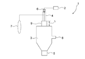
- FIG. 1 is a schematic view showing an example of a DC plasma device for producing the metal particles of the present invention.
- the metal particles of the present invention contain a magnetic metal element.
- the metal particles of the present invention may be composed of a single magnetic metal element, an alloy of two or more magnetic metal elements, or one or more magnetic metal elements and one or more magnetic metal elements. It may be composed of an alloy with the non-magnetic metal element.
- the magnetism referred to in the present invention means ferromagnetism. Therefore, the magnetic metal element used in the present invention has ferromagnetism.
- Fe when Fe is used, not only single Fe but also FeSi alloy (including FeSi, FeSiCr, FeSiAl, FeSiB), FeNi alloy (FeNi, FeNiMo, FeNiCr, FeNiCu, FeNiNb) is used as an alloy using Fe. And FeCo alloy (including FeCo, FeCoV, FeCoNi) and the like are preferably used.
- the metal particles of the present invention have a specific particle size distribution.
- the metal particles of the present invention have a volume cumulative particle diameter at a cumulative volume of 50 volume% measured by scanning electron microscope observation, and a volume cumulative volume at a cumulative volume of 50 volume% by a laser diffraction/scattering particle size distribution measurement method with respect to D SEM50 .
- the ratio D 50 /D SEM50 of the particle size D 50 is preferably 4 or less.
- D SEM 50 represents the particle size of the primary particles
- D 50 is the place that represents the particle size of the secondary particles is an aggregate of a plurality of primary particles
- D 50 / D SEM 50 is less than the above value
- the The metal particles of the invention have a low degree of aggregation between particles and a high proportion of primary particles. Due to this, the metal particles of the present invention have a good filling property, and it becomes easy to increase the saturation magnetic flux density.
- the primary particle is an object recognized as the minimum unit as a particle, judging from the geometrical appearance.
- the value of D 50 /D SEM50 is more preferably 3.0 or less, and further preferably 2.5 or less.
- the lower limit of D 50 /D SEM50 is theoretically 1, but 1.5 is realistic.
- the value of D 50 /D SEM50 is as described above, but the value of D 50 itself is preferably 3.0 ⁇ m or less, more preferably 2.0 ⁇ m or less, and further preferably 1.5 ⁇ m or less. More preferable.
- the lower limit is preferably 0.2 ⁇ m. It is preferable to set D 50 to this value or less, since it becomes easy to increase the saturation magnetic flux density while maintaining good handleability of the metal particles.
- the value of D SEM50 is preferably 0.20 ⁇ m or more, more preferably 0.25 ⁇ m or more, and further preferably 0.30 ⁇ m or more.
- the upper limit is preferably 1.5 ⁇ m, more preferably 1.0 ⁇ m, and even more preferably 0.8 ⁇ m.
- the metal particles of the present invention have a laser diffraction scattering for a volume cumulative particle diameter D SEM90 at a cumulative volume of 90% by volume measured by scanning electron microscope observation. It is preferable that the ratio D 90 /D SEM90 of the volume cumulative particle diameter D 90 at the cumulative volume of 90% by volume measured by the formula particle size distribution measurement method is 10 or less.
- D 90 /D SEM90 By setting D 90 /D SEM90 to 10 or less, when an inductor is manufactured using the metal particles of the present invention, the packing density of the metal particles can be increased, and an inductor having particularly high magnetism can be obtained. .. It is more preferable that D 90 /D SEM90 is 7 or less. The theoretical lower limit of D 90 /D SEM 90 is 1, but 2.5 is realistic.
- the value of D 90 /D SEM90 is as described above, and the value of D 90 itself is preferably 6.0 ⁇ m or less, more preferably 5.0 ⁇ m or less, and further preferably 4.5 ⁇ m or less. More preferable.
- the lower limit is preferably 0.3 ⁇ m. It is preferable to set the value of D 90 in this range because it becomes easy to increase the packing density of the metal particles.
- D SEM90 a condition that is greater than the value of D SEM 50 described above, it is preferably 0.3 ⁇ m or more, further preferably 0.4 ⁇ m or more, is 0.5 ⁇ m or more More preferably.
- the upper limit is preferably 3.0 ⁇ m, more preferably 2.5 ⁇ m, and even more preferably 1.5 ⁇ m. It is preferable to set the value of D SEM90 in this range because it becomes easy to increase the packing density of the metal particles.
- D SEM50 and D SEM90 were obtained by randomly selecting 1000 particles in which particles did not overlap each other from a scanning electron microscope image of metal particles and measuring the particle diameter (Haywood diameter). From the particle size, the volume when the particles are assumed to be spheres is calculated, and is defined as the volume cumulative particle size at 50% by volume and 90% by volume of the volume.
- the measurement of D 50 and D 90 can be performed, for example, by the following method. That is, 0.1 g of a measurement sample and 50 mL of water are mixed and dispersed with an ultrasonic homogenizer (manufactured by Nippon Seiki Seisakusho, US-300T) for 1 minute. Then, the particle size distribution is measured using, for example, MT3300 EXII manufactured by Microtrac Bell as a laser diffraction/scattering particle size distribution measuring device.
- an ultrasonic homogenizer manufactured by Nippon Seiki Seisakusho, US-300T
- the metal particles of the present invention having the above-mentioned structure have a particle size of submicron size without depending on the composition of the metal particles, but the particles are less likely to aggregate. Moreover, since the metal particles of the present invention have a particle size of submicron size and the particles do not agglomerate with each other, it is possible to enhance the filling property and, in turn, the saturation magnetic flux density.
- a method of blending a plurality of types of particles having different particle diameters in order to enhance the filling property of the particles.
- this method is not industrially and economically advantageous in that it is necessary to prepare a plurality of types of particles and that a mixing step is required.
- the metal particles of the present invention are industrially and economically advantageous in that the packing property of the particles can be improved by using only the metal particles.
- the crystallite size of the metal particles of the present invention is preferably 50 nm or more and 150 nm or less, more preferably 60 nm or more and 130 nm or less, and even more preferably 70 nm or more and 120 nm or less.
- metal particles having a large crystallite size in this way particles having few grain boundaries are formed and the purity is increased, so that the saturation magnetic flux density is improved, which is preferable.
- the metal particles having a crystallite size in this range can be suitably produced, for example, by the production method described below.
- the crystallite size varies depending on the type of metal particles used, but generally, from the peak width (half width) of the X-ray diffraction peak in the crystal plane with the highest intensity within the measurement range (20° to 150°), Calculated according to Scherrer's formula. For example, when FeCo alloy is used as the metal particles, CuK ⁇ rays are used to measure the X-ray diffraction of the metal particles at a measurement range (2 ⁇ : 20° to 150°), a sampling width of 0.01°, and a scan speed of 2°/min. It is calculated from the peak width (half-value width) of the X-ray diffraction peak on the crystal plane ⁇ 110> when the intensity is measured.
- the shape of the metal particles of the present invention is not particularly limited, and various shapes such as spherical shape, flake shape, and polyhedral shape can be adopted. From the viewpoint of enhancing the filling property of the metal particles and enhancing the saturation magnetic flux density, the shape of the metal particles is preferably spherical.
- the term “spherical” means that the circularity coefficient measured by the following method is preferably 0.85 or more, and more preferably 0.90 or more. The circularity coefficient is calculated by the following method. A scanning electron microscope image of metal particles is taken, and 1000 particles in which the particles do not overlap each other are randomly selected.
- the circularity coefficient of the particle is calculated from the formula of 4 ⁇ S/L 2 .
- the arithmetic mean value of the circularity coefficient of each particle is defined as the circularity coefficient described above.
- the circularity coefficient of the particle is 1.
- the metal particles of the present invention may further contain a non-magnetic metal element in addition to the magnetic metal material.
- the non-magnetic metal element is contained in the shell portion arranged on the surface of the core portion containing the magnetic metal element.
- the metal particle of the present invention comprises a core portion containing a magnetic metal element and a shell portion arranged on the surface of the core portion and containing an oxide of a non-magnetic metal element, which results in eddy current loss. Is more preferable from the viewpoint of further reduction.
- the shell portion containing the oxide of the non-magnetic metal element acts as an electrical insulating layer of the core portion, which further reduces eddy current loss.
- the shell part may be crystalline or amorphous as long as it has electric insulation.
- the non-magnetic metal element is at least one of Mg, Al, Si, Ca, Zr, Ti, Hf, Zn, Mn, rare earth elements (excluding those having magnetism), Ba and Sr. From the viewpoint of improving the electrical insulation of the shell portion, any one of Al, Si and Zr is more preferable. These non-magnetic metal elements may be used alone or in combination of two or more.
- the boiling point of the oxide of the element as the non-magnetic metal element constituting the shell portion is It is preferable to use the one having a boiling point lower than that from the viewpoint of easy production.
- the core part may be composed of only a magnetic metal element, or may be formed of an alloy containing both a magnetic metal element and a non-magnetic metal element.
- the shell portion is composed only of an oxide of a non-magnetic metal element and does not contain a magnetic metal element.
- the shell portion of the metal particle having the core portion and the shell portion uniformly covers the entire area of the core portion.
- an increase in the coating amount of the shell portion leads to a decrease in the magnetic force of the metal particles as a whole.
- the proportion of the shell portion in the whole metal particles is preferably 1.0% by mass or more and 5.0% by mass or less, and 1.0% by mass or more and 4.0% by mass or less. It is more preferable that the amount is 1.0% by mass or more and 3.0% by mass or less. With such a content ratio, the desired particle size distribution as referred to in the present invention can be facilitated.
- the ratio of the shell portion in the metal particles can be measured by converting the Si concentration obtained by ICP analysis to the SiO 2 concentration, for example, when the shell portion is made of SiO 2 . The same measurement can be performed when the shell portion is made of another substance.
- the thickness of the shell portion is preferably 0.5 nm or more and 40 nm or less, more preferably 0.5 nm or more and 30 nm or less, and 0.1. It is more preferably 5 nm or more and 20 nm or less.
- the thickness of the shell portion can be obtained by identifying the shell portion by observation of a cross section with a transmission electron microscope (TEM) and measurement with energy dispersive X-ray analysis (EDS), and measuring the thickness.
- TEM transmission electron microscope
- EDS energy dispersive X-ray analysis
- the mother powder containing a magnetic metal element is subjected to a direct current thermal plasma (hereinafter, also referred to as “DC plasma”) method to generate magnetic metal particles from the mother powder.
- DC plasma direct current thermal plasma
- the present manufacturing method supplies mother powder to a plasma flame in a laminar flow state generated in a chamber, gasifies the mother powder, and cools the gasified mother powder to produce magnetic metal particles.
- the magnetic metal particles are composed of a single magnetic metal element, as the mother powder, those composed of the single magnetic metal element may be used.
- the mother powder may be composed of the alloy.
- the mother powder made of FeCo alloy may be used.
- the method for producing the mother powder is not particularly limited, and for example, atomized powder, wet reduced powder, electrolytic powder, etc. can be used.
- the DC plasma device 1 includes a powder supply device 2, a chamber 3, a DC plasma torch 4, a recovery pot 5, a powder supply nozzle 6, a gas supply device 7, and a pressure adjusting device 8. Further, in the DC plasma device 1, an annular wall portion 9 surrounding the plasma flame is arranged outside the chamber 3 and directly below the plasma torch 4. In this device, the mother powder passes from the powder supply device 2 through the powder supply nozzle 6 into the DC plasma torch 4. A gas for generating thermal plasma (hereinafter also referred to as “plasma gas”) is supplied to the plasma torch 4 from the gas supply device 7, and a plasma flame is generated.
- plasma gas gas for generating thermal plasma
- the gasified mother powder is cooled and becomes a fine powder of magnetic metal particles in a recovery pot. It is accumulated in 5 and collected.
- the inside of the chamber 3 is controlled by the pressure adjusting device 8 so as to maintain a negative pressure relatively to the powder supply nozzle 6, thereby facilitating the supply of the mother powder to the DC plasma torch 4 and the plasma. It has a structure that stably generates a frame.
- the apparatus shown in FIG. 1 is an example of a DC plasma apparatus, and the production of metal particles of the present invention is not limited to this apparatus.
- the plasma flame it is preferable to adjust the plasma flame so that it becomes thick and long in the laminar flow state.
- Whether or not the plasma frame is in a laminar flow state is determined by observing the plasma frame from the side where the frame width is thickest and the aspect ratio of the frame length to the frame width (hereinafter, frame aspect ratio) is 3 or less. It can be determined by whether or not the above. Specifically, if the frame aspect ratio is 3 or more, it can be determined that the flow is laminar, and if it is less than 3, it can be determined that the flow is turbulent.
- the plasma output of the DC plasma device is preferably 2 kW or more and 100 kW or less, and more preferably 2 kW or more and 40 kW or less.
- the gas flow rate of the plasma gas is preferably 0.1 L/min or more and 25 L/min or less, and more preferably 0.5 L/min or more and 21 L/min or less.
- the plasma gas is preferably a reducing gas such as hydrogen gas or an inert gas such as nitrogen gas or argon gas.
- the plasma relative to the supply amount of mother powder is preferably 0.01 kW ⁇ min/g or more and 20 kW ⁇ min/g or less, and more preferably 0.05 kW ⁇ min/g or more and 15 kW ⁇ min/g or less.
- the plasma gas flow rate with respect to the plasma output Ratio (unit: L/(min ⁇ kW)) is preferably 0.50 or more and 2.00 or less, more preferably 0.70 or more and 1.70 or less, and still more preferably 0.75 or more and 1.50 or less.
- the plasma flame is generated under the condition that the annular wall portion 9 surrounding the plasma flame is arranged immediately below the plasma torch 4.
- the annular wall portion 9 refers to a portion different from the plasma torch 4 for generating plasma, and the annular wall portion 9 suppresses the temperature decrease of the plasma flame, thereby promoting grain growth, thereby having a desired particle size distribution.
- the metal particles can be obtained successfully.
- metal particles having a desired crystallite size can be successfully obtained.
- the ratio of the length of the annular wall portion 9 (the length indicated by the symbol L in FIG. 1) to the frame length of the plasma flame is 0. It is preferable to generate the plasma flame so as to be 0.05 or more and 0.90 or less, particularly 0.10 or more and 0.90 or less, and particularly 0.30 or more and 0.90 or less.
- the ratio of the inner diameter of the annular wall portion 9 to the diameter of the plasma frame is 0.03 or more and 0.55 or less, and particularly 0.06 or more and 0.55 or less. Particularly, it is preferable to generate the plasma flame so that the plasma flame becomes 0.15 or more and 0.55 or less.
- the annular wall portion 9 may be an annular body, and its cross-sectional shape is not particularly limited.
- an annular body having a circular or rectangular cross section can be used as the annular wall portion 9.
- the annular wall portion 9 is preferably an annular body, that is, a cylinder. In this case, it is preferable that the position of the center of the cross section of the torus and the position where the plasma flame is generated are substantially the same from the viewpoint of effectively suppressing the temperature decrease of the plasma flame.
- a base powder a first base powder containing a magnetic metal element and a non-magnetic powder are used.
- a mixture of a second mother powder made of an oxide of a metal element may be used.
- the particle diameter D 50 of the mother powder is preferably 3.0 ⁇ m or more and 50 ⁇ m or less, more preferably 5.0 ⁇ m in both the first mother powder and the second mother powder. It is 30 ⁇ m or less. Measurement of D 50 of the mother powder may be carried out in the same manner as the measurement of the D 50 of the above metal particles.
- the feed rate of the mother powder is preferably 5 g/min or more and 200 g/min or less, expressed as the total amount of the first mother powder and the second mother powder, and preferably 5 g/min. More preferably, it is 100 g/min or less.
- the ratio of the first mother powder and the second mother powder it is preferable that the total amount of the first mother powder and the second mother powder contains 1 to 5 mass% of the second mother powder.
- the shape of the mother powder is not particularly limited in both the first mother powder and the second mother powder, and examples thereof include a dendritic shape, a rod shape, a flake shape, a cubic shape, and a spherical shape. From the viewpoint of stabilizing the supply efficiency to the plasma torch, it is preferable to use spherical mother powder.
- the boiling points of the first mother powder and the second mother powder preferably have a specific relationship. Specifically, it is advantageous to use, as the first mother powder, one having a boiling point higher than that of the second mother powder.
- the mixed mother powder composed of the first mother powder and the second mother powder having such a temperature relationship, in the process of producing particles, first, the vaporized first mother powder is cooled and nucleation of the core portion is formed. , Agglomeration and condensation occur, and a core part is formed. Next, nucleation, aggregation and condensation of the evaporated and vaporized second mother powder (the second mother powder has a lower boiling point than that of the first mother powder) occur on the surface of the core portion to form a shell portion.
- a core portion containing a magnetic metal element by, for example, an atomization method, and form a non-magnetic metal element oxide layer on the surface thereof by a wet method.
- the surface of the core portion is easily oxidized during the formation of the oxide layer, which may reduce the magnetic force of the particles.
- the RF plasma method instead of the DC plasma method for forming the core portion, but the particles obtained by the RF plasma method are too small in size and easily agglomerate, so that the filling property of the particles is improved. I can't.
- the magnetic force decreases as the particle size decreases.
- the manufacturing method using the DC plasma method described above does not cause inconveniences such as a decrease in magnetic force and a decrease in filling property.
- the metal particles obtained in this way tend to be spherical in shape.
- the metal particles are suitably used as a raw material for a sintered body as a metal powder which is an aggregate thereof.
- This sintered body is preferably used as a core material of a power inductor, for example.
- the metal particles are composed of a core part and an electrically insulating shell part.
- a metal powder as an aggregate of metal particles may be mixed with a binder or a vehicle to be used as a magnetic paste.
- the above-mentioned metal powder or magnetic paste can be compression-molded into a dust core.
- a solidified molded product obtained by molding this paste into a predetermined shape and drying and solidifying it can be used as the core material of the power inductor.
- Example 1 Using the DC plasma device 1 shown in FIG. 1, metal particles composed of a core part made of a FeCo alloy and a shell part made of SiO 2 were manufactured as follows. Atomized powder (particle size 10 ⁇ m, spherical) made of FeCo alloy (Fe 50%, Co 50%) was used as the first mother powder. SiO 2 powder (specific surface area 50 m 2 /g, spherical) was used as the second mother powder. (Amount of second mother powder used)/(amount of first mother powder used+amount of second mother powder used) was 2.0%. The mixed mother powder obtained by mixing both mother powders was supplied to the apparatus 1.
- the supply amount was set to 12 g/min, and the mixed mother powder was supplied to the DC plasma torch 4 through the powder supply nozzle 6.
- a mixed gas of nitrogen gas and argon gas was used as the plasma gas.
- the flow rate of nitrogen gas was set to 6 L/min, and the flow rate of argon gas was set to 11 L/min.
- the plasma output was set to 22 kW.
- the plasma frame was photographed from the side where the frame width was observed thickest, and the image was binarized to measure the frame aspect ratio, which is the ratio of the frame length to the frame width. As a result, it was confirmed that the flame aspect ratio was 4 and the plasma flame was a laminar flow.
- a torus was used as the annular wall portion 9. Then, the ratio of the length of the annular wall portion 9 to the frame length of the plasma flame is 0.80, and the ratio of the inner diameter of the annular wall portion 9 to the diameter of the plasma flame is 0.50.
- a plasma flame was generated.
- Example 2 Metal particles in the same manner as in Example 1 except that the amount of (second mother powder used)/(first mother powder used+second mother powder used) was 1.5%.
- Example 1 In Example 1, (amount of second mother powder used)/(amount of first mother powder used+amount of second mother powder used) was set to 7%. Further, the annular wall portion 9 was not installed in the chamber 3 of the plasma device 1. Metal particles were obtained in the same manner as in Example 1 except for these.
- the saturation magnetization was measured using a vibrating sample magnetometer (VSM-5 manufactured by Toei Industry Co., Ltd.).
- the powder density was measured using a powder resistance measuring system (PD-51 manufactured by Mitsubishi Chemical Analytech) and a resistivity meter (MCP-T600 manufactured by Mitsubishi Chemical Analytech). 5 g of metal particles (sample) was put into the probe cylinder, and the probe unit was set on PD-51. The green compact density was calculated from the sample thickness when a load of 6.28 kN was applied by the hydraulic jack.
- the metal particles obtained in each example have a higher green density and a higher packing property than the metal particles obtained in the comparative example. Further, the metal particles obtained in each example were able to improve the saturation magnetization due to the fact that the ratio of the shell portion could be reduced as compared with the metal particles obtained in the comparative example.
- Example 3 In Example 1, the first mother powder was changed to atomized powder (particle diameter 10 ⁇ m, spherical) made of FeNi alloy (Fe 50%, Ni 50%). Further, (amount of second mother powder used)/(amount of first mother powder used+amount of second mother powder used) was changed to 1.5%. Except for these, in the same manner as in Example 1, metal particles were obtained.
- Example 3 In Example 3, the annular wall portion 9 was not installed in the chamber 3 of the plasma device 1. Otherwise in the same manner as in Example 3, metal particles were obtained.
- Example 3 As is clear from the results shown in Table 2, it can be seen that the metal particles obtained in Example 3 have a higher green compact density and a higher packing property than the metal particles obtained in Comparative Example 2.
Landscapes
- Powder Metallurgy (AREA)
- Manufacture Of Metal Powder And Suspensions Thereof (AREA)
- Soft Magnetic Materials (AREA)
Abstract
本発明は、充填性の高い金属粒子を提供することを目的とする。本発明の金属粒子は磁性金属元素を含有してなる。金属粒子の走査型電子顕微鏡観察による累積体積50容量%における体積累積粒径DSEM50に対するレーザー回折散乱式粒度分布測定法による累積体積50容量%における体積累積粒径D50の比D50/DSEM50が4以下である。DSEM50が0.2μm以上1.5μm以下である。金属粒子は、磁性金属元素を含有するコア部と、コア部の表面に配置され且つ非磁性金属元素の酸化物を含有するシェル部とを具備することが好適である。
Description
本発明は、金属粒子、それを用いた磁性体ペースト、圧粉磁心及びインダクタ、並びに金属粒子の製造方法に関する。
小型携帯機器の高機能化及び多機能化に伴い、当該機器に使用されるインダクタとして、大電流に対応したもの、すなわちパワーインダクタが必要となってきている。インダクタに大電流を流すためには、インダクタを構成する材料である磁性材料として、飽和磁束密度の高いものを用いることが有利である。インダクタに従来用いられてきた磁性材料は主としてフェライトであるところ、近年ではそれよりも飽和磁束密度の高い材料である金属系材料が注目されている。金属系を使用する際には、インダクタにおける渦電流損失を低減させるために絶縁コートを施したコアシェル粒子が通常必要とされている。
金属系の磁性材料としては、例えば、鉄、シリコン、クロム、アルミニウム、ニッケル、コバルトなどを含む合金が知られている(特許文献1参照)。同文献においては、粒子径の異なる複数種類の金属系の磁性粒子を組み合わせて用いることで、インダクタにおける渦電流損失を低減させ、高効率及び高インダクタンスを確保している。具体的には、同文献においては、平均粒径が10~28μmである第1金属磁性粒子と、平均粒径が1~4.5μmである第2金属磁性粒子と、表面に配置された絶縁膜を含み、粒径が300nm以下である第3金属磁性粒子とを含む、磁性体組成物が提案されている。
磁性材料の飽和磁束密度を高めるには、磁性粒子の充填性が重要な因子の一つである。この目的のためには、サブミクロンサイズの粒径を有する磁性粒子を用いることが有利である。しかしサブミクロンサイズの粒径を有する磁性粒子は、微粒であるがゆえに凝集しやすく、そのことに起因して混合が容易でない。その結果、粒子の充填性が低下しやすい。上述した特許文献1に記載の磁性粒子の混合物も充填性に課題を有するものである。したがって本発明の課題は、充填性の高い磁性粒子を提供することにある。
前記の課題を解決すべく本発明者は鋭意検討した結果、サブミクロンサイズの粒径を有する磁性粒子の粒度分布をコントロールすることが、粒子の充填性を高める点から有利であることを知見した。本発明はこの知見に基づきなされたものである。すなわち本発明は、磁性金属元素を含有してなる金属粒子であって、
前記金属粒子の走査型電子顕微鏡観察による累積体積50容量%における体積累積粒径DSEM50に対するレーザー回折散乱式粒度分布測定法による累積体積50容量%における体積累積粒径D50の比D50/DSEM50が4以下であり、
DSEM50が0.2μm以上1.5μm以下である金属粒子を提供することによって前記の課題を解決したものである。
前記金属粒子の走査型電子顕微鏡観察による累積体積50容量%における体積累積粒径DSEM50に対するレーザー回折散乱式粒度分布測定法による累積体積50容量%における体積累積粒径D50の比D50/DSEM50が4以下であり、
DSEM50が0.2μm以上1.5μm以下である金属粒子を提供することによって前記の課題を解決したものである。
また本発明は、前記の金属粒子の好適な製造方法として、
チャンバー内に発生させた層流状態のプラズマフレーム内に、磁性金属元素を含む母粉を供給して該プラズマフレーム内で該母粉をガス化し、ガス化した該母粉を冷却して金属粒子を生成させる工程を有し、
前記チャンバー外であって且つプラズマトーチの直下に、前記プラズマフレームを包囲する環状壁部を配置した状態下に前記プラズマフレームを発生させ、
前記プラズマフレームのフレーム長さに対する前記環状壁部の長さが0.05以上0.90以下となるように該プラズマフレームを発生させる金属粒子の製造方法を提供するものである。
チャンバー内に発生させた層流状態のプラズマフレーム内に、磁性金属元素を含む母粉を供給して該プラズマフレーム内で該母粉をガス化し、ガス化した該母粉を冷却して金属粒子を生成させる工程を有し、
前記チャンバー外であって且つプラズマトーチの直下に、前記プラズマフレームを包囲する環状壁部を配置した状態下に前記プラズマフレームを発生させ、
前記プラズマフレームのフレーム長さに対する前記環状壁部の長さが0.05以上0.90以下となるように該プラズマフレームを発生させる金属粒子の製造方法を提供するものである。
以下本発明を、その好ましい実施形態に基づき説明する。本発明の金属粒子は磁性金属元素を含有してなるものである。本発明の金属粒子は単一の磁性金属元素から構成されていてもよく、2種以上の磁性金属元素の合金から構成されていてもよく、あるいは1種以上の磁性金属元素と、1種以上の非磁性金属元素との合金から構成されていてもよい。本発明にいう磁性とは強磁性のことである。したがって本発明で用いられる磁性金属元素は強磁性を有する。本発明においては、強磁性を有する金属元素として、Fe、Co及びNiの少なくとも1種を用いることが、飽和磁束密度を高める観点及び経済性の観点から好ましい。これらの中でも、例えばFeを用いる場合、単一のFeだけでなく、Feを用いた合金としてFeSi合金(FeSi、FeSiCr、FeSiAl、FeSiBを含む)、FeNi合金(FeNi、FeNiMo、FeNiCr、FeNiCu、FeNiNbを含む)、FeCo合金(FeCo、FeCoV、FeCoNiを含む)などが好ましく用いられる。
本発明の金属粒子は、特定の粒度分布を有することを特徴の一つとするものである。詳細には、本発明の金属粒子は、走査型電子顕微鏡観察によって測定された累積体積50容量%における体積累積粒径DSEM50に対するレーザー回折散乱式粒度分布測定法による累積体積50容量%における体積累積粒径D50の比D50/DSEM50が4以下であることが好ましい。DSEM50は一次粒子の粒径を表し、D50は複数個の一次粒子の凝集体である二次粒子の粒径を表すところ、D50/DSEM50が上述した値以下であることによって、本発明の金属粒子は、粒子どうしの凝集の度合いが低く、一次粒子の割合が高いものとなる。このことに起因して、本発明の金属粒子は良好な充填性を有し、飽和磁束密度を高めることが容易となる。なお本発明において一次粒子とは、外見上の幾何学的形態から判断して、粒子としての最小単位と認められる物体のことである。
金属粒子の充填性を一層高める観点からD50/DSEM50の値は3.0以下であることが更に好ましく、2.5以下であることが一層好ましい。D50/DSEM50の下限値は理論的には1であるところ、1.5が現実的である。
D50/DSEM50の値は上述のとおりであるところ、D50そのものの値は3.0μm以下であることが好ましく、2.0μm以下であることが更に好ましく、1.5μm以下であることが一層好ましい。またその下限は、0.2μmであることが好ましい。D50をこの値以下に設定することで、金属粒子の取り扱い性を良好に維持しつつ、飽和磁束密度を高めることが容易となるので好ましい。
一方、DSEM50の値に関しては、0.20μm以上であることが好ましく、0.25μm以上であることが更に好ましく、0.30μm以上であることが一層好ましい。またその上限値は、1.5μmであることが好ましく、1.0μmであることが更に好ましく、0.8μmであることが一層好ましい。DSEM50の値をこの範囲に設定することで、金属粒子の取り扱い性を良好に維持しつつ、飽和磁束密度を高めることが容易となるので好ましい。
本発明の金属粒子は、D50/DSEM50の値が上述の範囲であることに加えて、走査型電子顕微鏡観察によって測定された累積体積90容量%における体積累積粒径DSEM90に対するレーザー回折散乱式粒度分布測定法による累積体積90容量%における体積累積粒径D90の比D90/DSEM90が10以下であることが好ましい。D90/DSEM90を10以下とすることで、本発明の金属粒子を用いてインダクタを製造した場合に、該金属粒子の充填密度を高めることができ、特に磁性の高いインダクタとすることができる。D90/DSEM90は7以下であることがより好ましい。D90/DSEM90の下限値は理論的には1であるところ、2.5が現実的である。
D90/DSEM90の値は上述のとおりであるところ、D90そのものの値は6.0μm以下であることが好ましく、5.0μm以下であることが更に好ましく、4.5μm以下であることが一層好ましい。またその下限は、0.3μmであることが好ましい。D90の値をこの範囲に設定することで、金属粒子の充填密度を高めることが容易となるので好ましい。
一方、DSEM90の値に関しては、上述したDSEM50の値よりも大きいことを条件として、0.3μm以上であることが好ましく、0.4μm以上であることが更に好ましく、0.5μm以上であることが一層好ましい。またその上限値は、3.0μmであることが好ましく、2.5μmであることが更に好ましく、1.5μmであることが一層好ましい。DSEM90の値をこの範囲に設定することで、金属粒子の充填密度を高めることが容易となるので好ましい。
本発明においてDSEM50及びDSEM90は、金属粒子の走査型電子顕微鏡像から、粒子どうしが重なり合っていないものを無作為に1000個選んで粒径(ヘイウッド径)を測定し、次いで、得られた粒径から、粒子が球であると仮定したときの体積を算出し、該体積の累積体積50容量%及び90容積%における体積累積粒径と定義される。
一方、D50及びD90の測定は、例えば以下の方法で行うことができる。すなわち、0.1gの測定試料と水50mLとを混合し、超音波ホモジナイザ(日本精機製作所製、US-300T)で1分間分散させる。その後、レーザー回折散乱式粒度分布測定装置として、例えばマイクロトラックベル製MT3300 EXIIを用いて粒度分布を測定する。
以上の構成を有する本発明の金属粒子は、金属粒子の組成に依存することなく、サブミクロンサイズの粒径を有しつつも、粒子どうしの凝集が少ないものである。また、本発明の金属粒子は、サブミクロンサイズの粒径を有し且つ粒子どうしの凝集が少ないので、充填性を高めることができ、ひいては飽和磁束密度を高めることができる。ところで、粒子の充填性を高めるために、粒径の異なる複数種類の粒子をブレンドする手法が知られている。しかしこの手法は、複数種類の粒子を用意する必要があるという点や、混合工程が必要であるという点で、工業的・経済的に有利とはいえない。これに対して本発明の金属粒子は、それのみを用いることで粒子の充填性を高め得るという点で、工業的・経済的に有利である。
本発明の金属粒子は、その結晶子サイズが50nm以上150nm以下であることが好ましく、60nm以上130nm以下であることが更に好ましく、70nm以上120nm以下であることが一層好ましい。このように結晶子サイズの大きい金属粒子とすることで粒界の少ない粒子となり純度が高くなるため、飽和磁束密度が向上するので好ましい。この範囲の結晶子サイズを有する金属粒子は、例えば後述する製造方法によって好適に製造することができる。
結晶子サイズは、用いる金属粒子の種類によってその測定方法が異なるが、概して測定範囲(20°~150°)内で最も強度の高い結晶面におけるX線回折ピークのピーク幅(半値幅)から下記のシェラーの式により算出する。例えば、金属粒子としてFeCo合金を用いる場合、CuKα線を使用して、測定範囲(2θ:20°~150°)、サンプリング幅0.01°、スキャンスピード 2°/minで金属粒子のX線回折強度を測定したときの結晶面<110>におけるX線回折ピークのピーク幅(半値幅)から算出される。
シェラーの式:D=Kλ/βcosθ
D:結晶子サイズ(単位:nm)
K:シェラー定数(0.9400)
λ:X線の波長(単位:Kα1 1.54056Å)
β:半値幅(単位:rad)
θ:回折角(単位:rad)
シェラーの式:D=Kλ/βcosθ
D:結晶子サイズ(単位:nm)
K:シェラー定数(0.9400)
λ:X線の波長(単位:Kα1 1.54056Å)
β:半値幅(単位:rad)
θ:回折角(単位:rad)
本発明の金属粒子の形状に特に制限はなく、例えば球状、フレーク状、多面体状など種々の形状を採用することができる。金属粒子の充填性を高め、飽和磁束密度を高める観点から、金属粒子の形状は、球状であることが好ましい。球状であるとは、以下の方法で測定した円形度係数が好ましくは0.85以上、更に好ましくは0.90以上であることをいう。円形度係数は、次の方法で算出される。金属粒子の走査型電子顕微鏡像を撮影し、粒子どうしが重なり合っていないものを無作為に1000個選び出す。粒子の二次元投影像の面積をSとし、周囲長をLとしたときに、粒子の円形度係数を4πS/L2の式から算出する。各粒子の円形度係数の算術平均値を上述した円形度係数とする。粒子の二次元投影像が真円である場合は、粒子の円形度係数は1となる。
本発明の金属粒子は、磁性金属材料を含むことに加えて、非磁性金属元素を更に含んでいてもよい。特に、非磁性金属元素は、磁性金属元素を含有するコア部の表面に配置されるシェル部に含有されていることが、渦電流損失の低減の観点から有利である。とりわけ、本発明の金属粒子は、磁性金属元素を含有するコア部と、該コア部の表面に配置され且つ非磁性金属元素の酸化物を含有するシェル部とを具備することが、渦電流損失の更に一層の低減の観点から好ましい。この非磁性金属元素の酸化物を含有するシェル部は、コア部の電気絶縁層として作用するので、そのことに起因して渦電流損失が一層低減する。シェル部は電気絶縁性を有する限りにおいて結晶質であってもよく、あるいは非晶質であってもよい。
前記の非磁性金属元素は、Mg、Al、Si、Ca、Zr、Ti、Hf、Zn、Mn、希土類元素(ただし磁性を有するものを除く。)、Ba及びSrの少なくとも1種であることが、シェル部の電気絶縁性を高める観点から好ましく、Al、Si及びZrのいずれかであることが一層好ましい。これらの非磁性金属元素は1種を単独で用いることもでき、あるいは2種以上を組み合わせて用いることもできる。
特に、後述する方法で、コア部及びシェル部を有する金属粒子を製造する場合には、シェル部を構成する非磁性金属元素として、該元素の酸化物の沸点が、コア部を構成する金属の沸点よりも低いものを用いることが、製造の容易さの点から好ましい。
コア部は、磁性金属元素のみから構成されていてもよく、あるいは磁性金属元素及び非磁性金属元素の双方を含む合金から形成されていてもよい。一方、シェル部は非磁性金属元素の酸化物のみからなり、磁性金属元素を非含有であることが好ましい。
コア部及びシェル部を有する金属粒子におけるシェル部は、電気絶縁性の観点からは、コア部の全域を満遍なく被覆していることが好ましい。しかし一方で、シェル部の被覆量が多くなることは、金属粒子全体としての磁力の低下につながる。これらの事項を勘案すると、金属粒子全体におけるシェル部の占める割合は、1.0質量%以上5.0質量%以下であることが好ましく、1.0質量%以上4.0質量%以下であることが更に好ましく、1.0質量%以上3.0質量%以下であることが一層好ましい。かかる含有割合とすることで、本発明でいう所望の粒度分布にしやすくすることもできる。金属粒子におけるシェル部の占める割合は、例えばシェル部がSiO2からなる場合には、ICP分析により得られるSi濃度からSiO2濃度に換算することによって測定することができる。シェル部が他の物質からなる場合も同様に測定できる。
シェル部がコア部の表面全域を被覆しているか否かにかかわらず、シェル部の厚みは0.5nm以上40nm以下であることが好ましく0.5nm以上30nm以下であることが更に好ましく、0.5nm以上20nm以下であることが一層好ましい。シェル部の厚みは、透過型電子顕微鏡(TEM)による断面観察、及びエネルギー分散型X線分析(EDS)による測定でシェル部を特定し、その厚みを測定することで求められる。
次に本発明の磁性粒子の好適な製造方法について説明する。本製造方法では、磁性金属元素を含む母粉を直流熱プラズマ(以下、「DCプラズマ」ともいう。)法に付して、該母粉から磁性金属粒子を生成させる。詳細には、本製造方法は、チャンバー内に発生させた層流状態のプラズマフレームに母粉を供給して、該母粉をガス化させ、ガス化した母粉を冷却して磁性金属粒子を生成させる工程を有する。磁性金属粒子が単一の磁性金属元素から構成される場合には、母粉として、当該単一の磁性金属元素からなるものを用いればよい。磁性金属粒子が2種以上の磁性金属元素の合金から構成される場合には、母粉として、当該合金からなるものを用いればよい。例えば目的とする磁性金属粒子がFeCo合金からなる場合には、FeCo合金からなる母粉を用いればよい。母粉の製造方法に特に制限はなく、例えばアトマイズ粉、湿式還元粉、電解粉等を用いることができる。
本製造方法に好適に用いられるDCプラズマ装置を図1に示す。同図に示すように、DCプラズマ装置1は、粉末供給装置2、チャンバー3、DCプラズマトーチ4、回収ポット5、粉末供給ノズル6、ガス供給装置7及び圧力調整装置8を備えている。更にDCプラズマ装置1には、チャンバー3外であって且つプラズマトーチ4の直下に、プラズマフレームを包囲する環状壁部9が配置されている。この装置においては、母粉は、粉末供給装置2から粉末供給ノズル6を通じてDCプラズマトーチ4内部を通過する。プラズマトーチ4には、熱プラズマ発生用のガス(以下「プラズマガス」ともいう。)がガス供給装置7から供給されプラズマフレームが発生する。また、DCプラズマトーチ4で発生させたプラズマフレーム内で母粉がガス化され、チャンバー3に放出された後、ガス化された母粉が冷却され、磁性金属粒子の微粉末となって回収ポット5内に蓄積回収される。チャンバー3の内部は、圧力調整装置8によって粉末供給ノズル6よりも相対的に陰圧が保持されるように制御されており、母粉のDCプラズマトーチ4への供給を容易にするとともに、プラズマフレームを安定して発生する構造をとっている。なお図1に示す装置は、DCプラズマ装置の一例であって、本発明の金属粒子の製造はこの装置に限定されるものではない。
プラズマフレーム内で母粉に十分なエネルギーを供給して、サブミクロンオーダーの微粒子を首尾よく形成する観点から、プラズマフレームが層流状態で太く長くなるように調整することが好ましい。プラズマフレームが層流状態であるか否かは、プラズマフレームを、フレーム幅が最も太く観察される側面から観察したときに、フレーム幅に対するフレーム長さの縦横比(以下、フレームアスペクト比)が3以上であるか否かによって判断することができる。具体的には、フレームアスペクト比が3以上であれば層流状態と判断することができ、3未満であれば乱流状態と判断することができる。
プラズマフレームが層流状態で太く長くなるようにするためには、プラズマ出力とプラズマガス流量を調整することが有利である。詳細には、DCプラズマ装置のプラズマ出力は、2kW以上100kW以下、更に2kW以上40kW以下であることが好ましい。プラズマガスのガス流量に関しては、0.1L/min以上25L/min以下であることが好ましく、0.5L/min以上21L/min以下であることが更に好ましい。プラズマガスとしては、水素ガス等の還元ガスや、窒素ガス及びアルゴンガス等の不活性ガスが好ましい。
プラズマフレーム内で十分な熱エネルギーを母粉に供給し、サブミクロンオーダーの微粒子を首尾よく形成する観点に加えて、粗粒の母粉を残存しにくくする観点から、母粉の供給量に対するプラズマ出力の比は、好ましくは0.01kW・min/g以上20kW・min/g以下であり、更に好ましくは0.05kW・min/g以上15kW・min/g以下である。
また、プラズマフレームを層流状態に安定的に保ちつつ、母粉のガス化に必要な流速を確実に得る観点から、上述の範囲のプラズマ出力及びガス流量を保ちつつ、プラズマ出力に対するプラズマガス流量の比(単位:L/(min・kW))を、好ましくは0.50以上2.00以下、より好ましくは0.70以上1.70以下、更に好ましくは0.75以上1.50以下に設定する。
特に本製造方法においては、図1に示すとおり、プラズマトーチ4の直下に、プラズマフレームを包囲する環状壁部9を配置した状態下にプラズマフレームを発生させるようにしている。環状壁部9はプラズマを発生させるプラズマトーチ4とは異なる部位をいい、この環状壁部9によってプラズマフレームの温度低下を抑制し、それによって粒成長を促進させることで、所望の粒度分布を有する金属粒子を首尾よく得ることができるものである。また、所望の結晶子サイズを有する金属粒子を首尾よく得ることができる。
環状壁部9を用いることでプラズマフレームの温度低下を一層抑制する観点から、プラズマフレームのフレーム長さに対する環状壁部9の長さ(図1中、符号Lで示す長さ)の比が0.05以上0.90以下、特に0.10以上0.90以下、とりわけ0.30以上0.90以下となるようにプラズマフレームを発生させることが好ましい。
同様の観点から、環状壁部9が円環体である場合、プラズマフレームの直径に対する環状壁部9の内径の比が、0.03以上0.55以下、特に0.06以上0.55以下、とりわけ0.15以上0.55以下となるようにプラズマフレームを発生させることが好ましい。
環状壁部9は、環状体であればよく、その断面形状に特に制限はない。例えば断面が円形や矩形の環状体を環状壁部9として用いることができる。プラズマフレームの温度低下を効果的に抑制する観点からは、環状壁部9は円環体、つまり円筒であることが好ましい。この場合、円環体における横断面の中心の位置と、プラズマフレームの発生位置とが概ね一致していることが、プラズマフレームの温度低下を効果的に抑制する観点から好ましい。
図1に示すDCプラズマ装置1を用いて、コア部と電気絶縁性のシェル部とを有する金属粒子を製造する場合には、母粉として、磁性金属元素を含む第1母粉と、非磁性金属元素の酸化物からなる第2母粉とを混合したものを用いればよい。母粉のプラズマ噴射性とコストの観点から、母粉の粒径D50は、第1母粉及び第2母粉のいずれにおいても、好ましくは3.0μm以上50μm以下、更に好ましくは5.0μm以上30μm以下である。母粉のD50の測定は、上述した金属粒子のD50の測定と同様の方法で行うことができる。
得られる金属粒子の製造効率の観点から、母粉の供給量は、第1母粉及び第2母粉の合計量で表して5g/min以上200g/min以下であることが好ましく、5g/min以上100g/min以下であることが更に好ましい。また、第1母粉と第2母粉との割合に関しては、第1母粉と第2母粉との合計中に第2母粉が1~5質量%含まれることが好ましい。
母粉の形状は、第1母粉及び第2母粉のいずれにおいても特に制限はなく、例えば樹枝状、棒状、フレーク状、キュービック状、球状などが挙げられる。プラズマトーチへの供給効率を安定化させる観点から、球状の母粉を用いることが好ましい。
第1母粉と第2母粉とはそれらの沸点が特定の関係にあることが好ましい。詳細には、第1母粉としてその沸点が第2母粉の沸点よりも高いものを用いることが有利である。このような温度関係を有する第1母粉及び第2母粉からなる混合母粉を用いることで、粒子の生成過程において、先ず、蒸発気化した第1母粉が冷却されてコア部の核形成、凝集及び凝縮が起こり、コア部が形成される。次いで、蒸発気化した第2母粉(第2母粉は第1母粉よりも沸点が低い。)の冷却による核形成、凝集及び凝縮が、コア部の表面で起こりシェル部が形成される。
上述した方法以外にも、例えばアトマイズ法によって磁性金属元素を含むコア部を形成し、その表面に湿式で非磁性金属元素の酸化物層を形成することも可能である。しかし、その場合には、酸化物層の形成時にコア部の表面が酸化されやすく、そのことに起因して、粒子の磁力が低下するおそれがある。また、コア部の形成にDCプラズマ法ではなく、RFプラズマ法を用いることも可能であるが、RFプラズマ法で得られた粒子は粒径が小さ過ぎて凝集しやすく、粒子の充填性を高めることができない。また粒径が小さくなるほど磁力が低下するという不都合もある。これらの方法に対して、上述のDCプラズマ法を用いた製造方法では、磁力の低下や充填性の低下などの不都合は生じない。
このようにして得られた金属粒子は、その形状が球状となりやすい。この金属粒子はその集合体である金属粉として、焼結体の原料に好適に用いられる。この焼結体は例えばパワーインダクタのコア材として好適に用いられる。この場合、渦電流損失の低減の観点から、金属粒子は、コア部と電気絶縁性のシェル部とから構成されていることが有利である。一方、金属粒子の集合体としての金属粉にバインダやビヒクルを含有させて磁性体ペーストの状態にして用いることもできる。また、上述した金属粉や磁性体ペーストを圧縮成形して圧粉磁心にすることもできる。更に、このペーストを所定形状に成形して乾燥固化させた固化成形体を、パワーインダクタのコア材として用いることもできる。
以下、実施例により本発明を更に詳細に説明する。しかしながら本発明の範囲は、かかる実施例に制限されない。特に断らない限り、「%」は「質量%」を意味する。
〔実施例1〕
図1に示すDCプラズマ装置1を用いて、下記に従いFeCo合金からなるコア部と、SiO2からなるシェル部とから構成される金属粒子を製造した。
第1母粉としてFeCo合金(Fe50%、Co50%)からなるアトマイズ粉(粒径10μm、球状)を用いた。第2母粉としてSiO2粉(比表面積50m2/g、球状)を用いた。(第2母粉の使用量)/(第1母粉の使用量+第2母粉の使用量)を2.0%とした。両母粉を混合して得られた混合母粉を装置1に供給した。供給量を12g/分に設定し、粉末供給ノズル6を通じてDCプラズマトーチ4に混合母粉を供給した。プラズマガスとしては、窒素ガスとアルゴンガスとの混合ガスを用いた。窒素ガスの流量は6L/分に設定し、アルゴンガスの流量は11L/分に設定した。また、プラズマ出力は22kWに設定した。生成したプラズマフレームについて、フレーム幅が最も太く観察される側面から該プラズマフレームを写真撮影し、画像を二値化してフレーム幅に対するフレーム長さの比であるフレームアスペクト比を測定した。その結果、フレームアスペクト比は4であり、プラズマフレームは層流であることが確認された。また、環状壁部9としては円環体を用いた。そして、プラズマフレームのフレーム長さに対する環状壁部9の長さの比が0.80となるように、且つプラズマフレームの直径に対する環状壁部9の内径の比が、0.50となるようにプラズマフレームを発生させた。
図1に示すDCプラズマ装置1を用いて、下記に従いFeCo合金からなるコア部と、SiO2からなるシェル部とから構成される金属粒子を製造した。
第1母粉としてFeCo合金(Fe50%、Co50%)からなるアトマイズ粉(粒径10μm、球状)を用いた。第2母粉としてSiO2粉(比表面積50m2/g、球状)を用いた。(第2母粉の使用量)/(第1母粉の使用量+第2母粉の使用量)を2.0%とした。両母粉を混合して得られた混合母粉を装置1に供給した。供給量を12g/分に設定し、粉末供給ノズル6を通じてDCプラズマトーチ4に混合母粉を供給した。プラズマガスとしては、窒素ガスとアルゴンガスとの混合ガスを用いた。窒素ガスの流量は6L/分に設定し、アルゴンガスの流量は11L/分に設定した。また、プラズマ出力は22kWに設定した。生成したプラズマフレームについて、フレーム幅が最も太く観察される側面から該プラズマフレームを写真撮影し、画像を二値化してフレーム幅に対するフレーム長さの比であるフレームアスペクト比を測定した。その結果、フレームアスペクト比は4であり、プラズマフレームは層流であることが確認された。また、環状壁部9としては円環体を用いた。そして、プラズマフレームのフレーム長さに対する環状壁部9の長さの比が0.80となるように、且つプラズマフレームの直径に対する環状壁部9の内径の比が、0.50となるようにプラズマフレームを発生させた。
〔実施例2〕
実施例1において、(第2母粉の使用量)/(第1母粉の使用量+第2母粉の使用量)を1.5%とした以外は実施例1と同様にして金属粒子を得た。
実施例1において、(第2母粉の使用量)/(第1母粉の使用量+第2母粉の使用量)を1.5%とした以外は実施例1と同様にして金属粒子を得た。
〔比較例1〕
実施例1において、(第2母粉の使用量)/(第1母粉の使用量+第2母粉の使用量)を7%とした。また、プラズマ装置1のチャンバー3内に環状壁部9を設置しなかった。これら以外は実施例1と同様にして金属粒子を得た。
実施例1において、(第2母粉の使用量)/(第1母粉の使用量+第2母粉の使用量)を7%とした。また、プラズマ装置1のチャンバー3内に環状壁部9を設置しなかった。これら以外は実施例1と同様にして金属粒子を得た。
〔評価〕
実施例及び比較例で得られた金属粒子について、上述の方法でDSEM50、D50、DSEM90、D90、円形度係数、コア部の結晶子サイズ及びシェル部の厚みを測定した。更に以下の方法で飽和磁化及び圧粉密度を測定した。それらの結果を以下の表1に示す。
実施例及び比較例で得られた金属粒子について、上述の方法でDSEM50、D50、DSEM90、D90、円形度係数、コア部の結晶子サイズ及びシェル部の厚みを測定した。更に以下の方法で飽和磁化及び圧粉密度を測定した。それらの結果を以下の表1に示す。
〔飽和磁化の測定方法〕
振動試料型磁力計(東英工業社製 VSM-5)を用いて飽和磁化を測定した。
振動試料型磁力計(東英工業社製 VSM-5)を用いて飽和磁化を測定した。
〔圧粉密度の測定方法〕
圧粉抵抗測定システム(三菱化学アナリテック社製 PD-51)と抵抗率測定器(三菱化学アナリテック社製 MCP-T600)を用いて圧粉密度を測定した。金属粒子(サンプル)5gをプローブシリンダへ投入し、プローブユニットをPD-51へセットした。油圧ジャッキによって6.28kNの荷重をかけたときの試料厚みから、圧粉密度を算出した。
圧粉抵抗測定システム(三菱化学アナリテック社製 PD-51)と抵抗率測定器(三菱化学アナリテック社製 MCP-T600)を用いて圧粉密度を測定した。金属粒子(サンプル)5gをプローブシリンダへ投入し、プローブユニットをPD-51へセットした。油圧ジャッキによって6.28kNの荷重をかけたときの試料厚みから、圧粉密度を算出した。

表1に示す結果から明らかなとおり、各実施例で得られた金属粒子は、比較例で得られた金属粒子に比べて圧粉密度が高く、充填性が高いものであることが判る。また、各実施例で得られた金属粒子は、比較例で得られた金属粒子に比べてシェル部の割合を低減することができたことに起因して、飽和磁化も改善できた。
〔実施例3〕
実施例1において、第1母粉をFeNi合金(Fe50%、Ni50%)からなるアトマイズ粉(粒径10μm、球状)に変更した。また、(第2母粉の使用量)/(第1母粉の使用量+第2母粉の使用量)を1.5%に変更した。これら以外は実施例1と同様にして、金属粒子を得た。
実施例1において、第1母粉をFeNi合金(Fe50%、Ni50%)からなるアトマイズ粉(粒径10μm、球状)に変更した。また、(第2母粉の使用量)/(第1母粉の使用量+第2母粉の使用量)を1.5%に変更した。これら以外は実施例1と同様にして、金属粒子を得た。
〔比較例2〕
実施例3において、プラズマ装置1のチャンバー3内に環状壁部9を設置しなかった。これ以外は実施例3と同様にして、金属粒子を得た。
実施例3において、プラズマ装置1のチャンバー3内に環状壁部9を設置しなかった。これ以外は実施例3と同様にして、金属粒子を得た。
〔評価〕
実施例3及び比較例2で得られた金属粒子について、上述の方法でDSEM50、D50、DSEM90、D90、円形度係数、コア部の結晶子サイズ、飽和磁化及び圧粉密度を測定した。それらの結果を以下の表2に示す。
実施例3及び比較例2で得られた金属粒子について、上述の方法でDSEM50、D50、DSEM90、D90、円形度係数、コア部の結晶子サイズ、飽和磁化及び圧粉密度を測定した。それらの結果を以下の表2に示す。
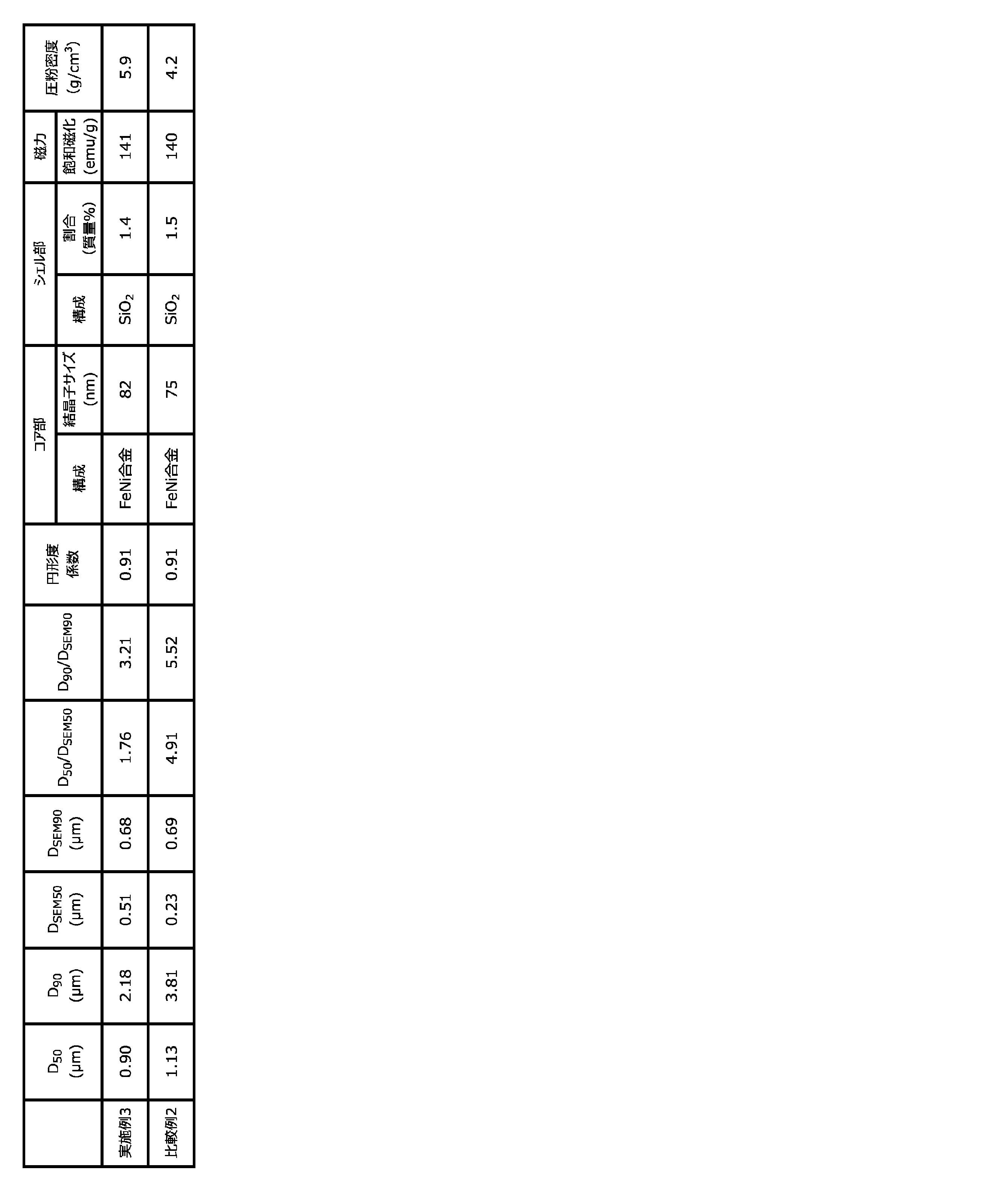
表2に示す結果から明らかなとおり、実施例3で得られた金属粒子は、比較例2で得られた金属粒子に比べて圧粉密度が高く、充填性が高いものであることが判る。
本発明によれば、充填性の高い金属粒子が得られる。この金属粒子を用いることで、飽和磁束密度の高いインダクタを容易に得ることが可能となる。
1 DCプラズマ装置
2 粉末供給装置
3 チャンバー
4 DCプラズマトーチ
5 回収ポット
6 粉末供給ノズル
7 ガス供給装置
8 圧力調整装置
9 環状壁部
2 粉末供給装置
3 チャンバー
4 DCプラズマトーチ
5 回収ポット
6 粉末供給ノズル
7 ガス供給装置
8 圧力調整装置
9 環状壁部
Claims (13)
- 磁性金属元素を含有してなる金属粒子であって、
前記金属粒子の走査型電子顕微鏡観察による累積体積50容量%における体積累積粒径DSEM50に対するレーザー回折散乱式粒度分布測定法による累積体積50容量%における体積累積粒径D50の比D50/DSEM50が4以下であり、
DSEM50が0.2μm以上1.5μm以下である金属粒子。 - D50が3.0μm以下である請求項1に記載の金属粒子。
- 前記金属粒子の走査型電子顕微鏡観察による累積体積90容量%における体積累積粒径DSEM90に対するレーザー回折散乱式粒度分布測定法による累積体積90容量%における体積累積粒径D90の比D90/DSEM90が10以下である請求項1又は2に記載の金属粒子。
- 結晶子サイズが50nm以上150nm以下である請求項1ないし3のいずれか一項に記載の金属粒子。
- 球状である請求項1ないし4のいずれか一項に記載の金属粒子。
- 前記磁性金属元素は、Fe、Co及びNiの少なくとも1種を含む請求項1ないし5のいずれか一項に記載の金属粒子。
- 非磁性金属元素を更に含んでなり、
前記非磁性金属元素は、Mg、Al、Si、Ca、Zr、Ti、Hf、Zn、Mn、希土類元素(ただし磁性を有するものを除く。)、Ba及びSrの少なくとも1種である請求項1ないし6のいずれか一項に記載の金属粒子。 - 磁性金属元素を含有するコア部と、
前記コア部の表面に配置され且つ非磁性金属元素の酸化物を含有するシェル部とを具備する請求項7に記載の金属粒子。 - 金属粒子におけるシェル部の占める割合が、1.0質量%以上5.0質量%以下である請求項8に記載の金属粒子。
- 請求項1ないし9のいずれか一項に記載の金属粒子を含んでなる磁性体ペースト。
- 請求項1ないし9のいずれか一項に記載の金属粒子を含んでなる圧粉磁心。
- 請求項1ないし9のいずれか一項に記載の金属粒子を含んでなるインダクタ。
- チャンバー内に発生させた層流状態のプラズマフレーム内に、磁性金属元素を含む母粉を供給して該プラズマフレーム内で該母粉をガス化し、ガス化した該母粉を冷却して金属粒子を生成させる工程を有し、
前記チャンバー外であって且つプラズマトーチの直下に、前記プラズマフレームを包囲する環状壁部を配置した状態下に前記プラズマフレームを発生させ、
前記プラズマフレームのフレーム長さに対する前記環状壁部の長さの比が0.05以上0.90以下となるように該プラズマフレームを発生させる金属粒子の製造方法。
Priority Applications (2)
| Application Number | Priority Date | Filing Date | Title |
|---|---|---|---|
| JP2020569575A JP7374932B2 (ja) | 2019-01-28 | 2020-01-24 | 金属粒子、それを用いた磁性体ペースト、圧粉磁心及びインダクタ、並びに金属粒子の製造方法 |
| CN202080006577.7A CN113165067B (zh) | 2019-01-28 | 2020-01-24 | 金属粒子、使用了其的磁性体膏糊、压粉磁心及感应器以及金属粒子的制造方法 |
Applications Claiming Priority (2)
| Application Number | Priority Date | Filing Date | Title |
|---|---|---|---|
| JP2019012581 | 2019-01-28 | ||
| JP2019-012581 | 2019-01-28 |
Publications (1)
| Publication Number | Publication Date |
|---|---|
| WO2020158593A1 true WO2020158593A1 (ja) | 2020-08-06 |
Family
ID=71842224
Family Applications (1)
| Application Number | Title | Priority Date | Filing Date |
|---|---|---|---|
| PCT/JP2020/002474 Ceased WO2020158593A1 (ja) | 2019-01-28 | 2020-01-24 | 金属粒子、それを用いた磁性体ペースト、圧粉磁心及びインダクタ、並びに金属粒子の製造方法 |
Country Status (3)
| Country | Link |
|---|---|
| JP (1) | JP7374932B2 (ja) |
| CN (1) | CN113165067B (ja) |
| WO (1) | WO2020158593A1 (ja) |
Citations (1)
| Publication number | Priority date | Publication date | Assignee | Title |
|---|---|---|---|---|
| JP2013089929A (ja) * | 2011-10-24 | 2013-05-13 | Tdk Corp | 軟磁性粉末、圧粉磁芯、及び磁気デバイス |
Family Cites Families (6)
| Publication number | Priority date | Publication date | Assignee | Title |
|---|---|---|---|---|
| JP4942333B2 (ja) * | 2005-11-29 | 2012-05-30 | 住友金属鉱山株式会社 | ニッケル粉およびその製造方法、ならびに該ニッケル粉を用いたポリマーptc素子 |
| JP5365487B2 (ja) * | 2008-12-11 | 2013-12-11 | 東ソー株式会社 | 表面が平滑なセラミックビーズおよびその製造方法 |
| JP6352731B2 (ja) * | 2013-09-20 | 2018-07-04 | 株式会社東芝 | 磁性金属粒子集合体及び電波吸収体 |
| WO2015122251A1 (ja) * | 2014-02-14 | 2015-08-20 | 三井金属鉱業株式会社 | 銅粉 |
| JP6250853B2 (ja) * | 2016-03-31 | 2017-12-20 | 本田技研工業株式会社 | 非水系電解質二次電池用正極活物質 |
| JP2018070935A (ja) * | 2016-10-27 | 2018-05-10 | 株式会社東北マグネットインスティテュート | ナノ結晶合金粉末及び磁性部品 |
-
2020
- 2020-01-24 WO PCT/JP2020/002474 patent/WO2020158593A1/ja not_active Ceased
- 2020-01-24 CN CN202080006577.7A patent/CN113165067B/zh active Active
- 2020-01-24 JP JP2020569575A patent/JP7374932B2/ja active Active
Patent Citations (1)
| Publication number | Priority date | Publication date | Assignee | Title |
|---|---|---|---|---|
| JP2013089929A (ja) * | 2011-10-24 | 2013-05-13 | Tdk Corp | 軟磁性粉末、圧粉磁芯、及び磁気デバイス |
Also Published As
| Publication number | Publication date |
|---|---|
| CN113165067A (zh) | 2021-07-23 |
| JP7374932B2 (ja) | 2023-11-07 |
| CN113165067B (zh) | 2023-03-14 |
| JPWO2020158593A1 (ja) | 2021-12-02 |
Similar Documents
| Publication | Publication Date | Title |
|---|---|---|
| JP5710427B2 (ja) | 磁性材料、磁性材料の製造方法および磁性材料を用いたインダクタ素子 | |
| CN104685582B (zh) | 软磁性混合粉末 | |
| CN104658733B (zh) | 磁性材料及磁性材料的制造方法 | |
| US20100207052A1 (en) | Method for producing magnetic particle | |
| CN105934532B (zh) | 磁控溅射用靶 | |
| Marinca et al. | Synthesis and characterization of the NiFe2O4/Ni3Fe nanocomposite powder and compacts obtained by mechanical milling and spark plasma sintering | |
| CN112105472B (zh) | 磁芯用粉末、使用其的磁芯和线圈部件 | |
| JP2004259807A (ja) | 圧粉磁芯用磁性粉末、および圧粉磁芯 | |
| Volodchenkov et al. | Nanoscale integration of oxides and metals in bulk 3D composites: leveraging SrFe12O19/Co interfaces for magnetic exchange coupling | |
| JP7374932B2 (ja) | 金属粒子、それを用いた磁性体ペースト、圧粉磁心及びインダクタ、並びに金属粒子の製造方法 | |
| JP7742238B2 (ja) | 金属粒子の製造方法 | |
| TW200301308A (en) | Ni-Fe base alloy powder | |
| JP7177393B2 (ja) | 軟磁性金属粉末 | |
| Luong et al. | Co–Pt nanoparticles encapsulated in carbon cages prepared by sonoelectrodeposition | |
| JP2025151177A (ja) | 金属粉末及びその製造方法 | |
| Zhang et al. | Characterization of magnetic FeCo particles with controlled bimetallic composition | |
| Suetsuna et al. | Synthesis of self-forming core/shell nanoparticles of magnetic metal/nonmagnetic oxide | |
| Genc et al. | Synthesis of AlNiCo core/shell nanopowders | |
| JP7133666B2 (ja) | 軟磁性扁平粉末 | |
| JP2019196526A (ja) | 鉄系合金粒子及びその製造方法 | |
| JP2010024479A (ja) | 鉄合金扁平微粒子及びその製造方法 | |
| JP2025060427A (ja) | 磁性金属粉末及びその製造方法 | |
| JP2023032113A (ja) | 合金粒子 | |
| JP7776984B2 (ja) | 希土類系磁石粉末、ボンド磁石、ボンド磁石用コンパウンド、焼結磁石、希土類系磁石粉末の製造方法および希土類系永久磁石の製造方法 | |
| US20220293310A1 (en) | Rare-earth-based magnet powder, bonded magnet, bonded magnet compound, sintered magnet, method of manufacturing rare-earth-based magnet powder, and method of manufacturing rare-earth based permanent magnet |
Legal Events
| Date | Code | Title | Description |
|---|---|---|---|
| 121 | Ep: the epo has been informed by wipo that ep was designated in this application |
Ref document number: 20749221 Country of ref document: EP Kind code of ref document: A1 |
|
| ENP | Entry into the national phase |
Ref document number: 2020569575 Country of ref document: JP Kind code of ref document: A |
|
| NENP | Non-entry into the national phase |
Ref country code: DE |
|
| 122 | Ep: pct application non-entry in european phase |
Ref document number: 20749221 Country of ref document: EP Kind code of ref document: A1 |