WO2020158152A1 - ブレーキ制御装置 - Google Patents
ブレーキ制御装置 Download PDFInfo
- Publication number
- WO2020158152A1 WO2020158152A1 PCT/JP2019/046721 JP2019046721W WO2020158152A1 WO 2020158152 A1 WO2020158152 A1 WO 2020158152A1 JP 2019046721 W JP2019046721 W JP 2019046721W WO 2020158152 A1 WO2020158152 A1 WO 2020158152A1
- Authority
- WO
- WIPO (PCT)
- Prior art keywords
- liquid passage
- control device
- brake control
- brake
- discharge
- Prior art date
- Legal status (The legal status is an assumption and is not a legal conclusion. Google has not performed a legal analysis and makes no representation as to the accuracy of the status listed.)
- Ceased
Links
Images






Classifications
-
- B—PERFORMING OPERATIONS; TRANSPORTING
- B60—VEHICLES IN GENERAL
- B60T—VEHICLE BRAKE CONTROL SYSTEMS OR PARTS THEREOF; BRAKE CONTROL SYSTEMS OR PARTS THEREOF, IN GENERAL; ARRANGEMENT OF BRAKING ELEMENTS ON VEHICLES IN GENERAL; PORTABLE DEVICES FOR PREVENTING UNWANTED MOVEMENT OF VEHICLES; VEHICLE MODIFICATIONS TO FACILITATE COOLING OF BRAKES
- B60T7/00—Brake-action initiating means
- B60T7/02—Brake-action initiating means for personal initiation
- B60T7/04—Brake-action initiating means for personal initiation foot actuated
- B60T7/042—Brake-action initiating means for personal initiation foot actuated by electrical means, e.g. using travel or force sensors
-
- B—PERFORMING OPERATIONS; TRANSPORTING
- B60—VEHICLES IN GENERAL
- B60T—VEHICLE BRAKE CONTROL SYSTEMS OR PARTS THEREOF; BRAKE CONTROL SYSTEMS OR PARTS THEREOF, IN GENERAL; ARRANGEMENT OF BRAKING ELEMENTS ON VEHICLES IN GENERAL; PORTABLE DEVICES FOR PREVENTING UNWANTED MOVEMENT OF VEHICLES; VEHICLE MODIFICATIONS TO FACILITATE COOLING OF BRAKES
- B60T13/00—Transmitting braking action from initiating means to ultimate brake actuator with power assistance or drive; Brake systems incorporating such transmitting means, e.g. air-pressure brake systems
- B60T13/10—Transmitting braking action from initiating means to ultimate brake actuator with power assistance or drive; Brake systems incorporating such transmitting means, e.g. air-pressure brake systems with fluid assistance, drive, or release
- B60T13/12—Transmitting braking action from initiating means to ultimate brake actuator with power assistance or drive; Brake systems incorporating such transmitting means, e.g. air-pressure brake systems with fluid assistance, drive, or release the fluid being liquid
- B60T13/14—Transmitting braking action from initiating means to ultimate brake actuator with power assistance or drive; Brake systems incorporating such transmitting means, e.g. air-pressure brake systems with fluid assistance, drive, or release the fluid being liquid using accumulators or reservoirs fed by pumps
- B60T13/142—Systems with master cylinder
- B60T13/145—Master cylinder integrated or hydraulically coupled with booster
- B60T13/146—Part of the system directly actuated by booster pressure
-
- B—PERFORMING OPERATIONS; TRANSPORTING
- B60—VEHICLES IN GENERAL
- B60T—VEHICLE BRAKE CONTROL SYSTEMS OR PARTS THEREOF; BRAKE CONTROL SYSTEMS OR PARTS THEREOF, IN GENERAL; ARRANGEMENT OF BRAKING ELEMENTS ON VEHICLES IN GENERAL; PORTABLE DEVICES FOR PREVENTING UNWANTED MOVEMENT OF VEHICLES; VEHICLE MODIFICATIONS TO FACILITATE COOLING OF BRAKES
- B60T13/00—Transmitting braking action from initiating means to ultimate brake actuator with power assistance or drive; Brake systems incorporating such transmitting means, e.g. air-pressure brake systems
- B60T13/10—Transmitting braking action from initiating means to ultimate brake actuator with power assistance or drive; Brake systems incorporating such transmitting means, e.g. air-pressure brake systems with fluid assistance, drive, or release
- B60T13/66—Electrical control in fluid-pressure brake systems
- B60T13/662—Electrical control in fluid-pressure brake systems characterised by specified functions of the control system components
-
- B—PERFORMING OPERATIONS; TRANSPORTING
- B60—VEHICLES IN GENERAL
- B60T—VEHICLE BRAKE CONTROL SYSTEMS OR PARTS THEREOF; BRAKE CONTROL SYSTEMS OR PARTS THEREOF, IN GENERAL; ARRANGEMENT OF BRAKING ELEMENTS ON VEHICLES IN GENERAL; PORTABLE DEVICES FOR PREVENTING UNWANTED MOVEMENT OF VEHICLES; VEHICLE MODIFICATIONS TO FACILITATE COOLING OF BRAKES
- B60T13/00—Transmitting braking action from initiating means to ultimate brake actuator with power assistance or drive; Brake systems incorporating such transmitting means, e.g. air-pressure brake systems
- B60T13/10—Transmitting braking action from initiating means to ultimate brake actuator with power assistance or drive; Brake systems incorporating such transmitting means, e.g. air-pressure brake systems with fluid assistance, drive, or release
- B60T13/66—Electrical control in fluid-pressure brake systems
- B60T13/68—Electrical control in fluid-pressure brake systems by electrically-controlled valves
- B60T13/686—Electrical control in fluid-pressure brake systems by electrically-controlled valves in hydraulic systems or parts thereof
-
- B—PERFORMING OPERATIONS; TRANSPORTING
- B60—VEHICLES IN GENERAL
- B60T—VEHICLE BRAKE CONTROL SYSTEMS OR PARTS THEREOF; BRAKE CONTROL SYSTEMS OR PARTS THEREOF, IN GENERAL; ARRANGEMENT OF BRAKING ELEMENTS ON VEHICLES IN GENERAL; PORTABLE DEVICES FOR PREVENTING UNWANTED MOVEMENT OF VEHICLES; VEHICLE MODIFICATIONS TO FACILITATE COOLING OF BRAKES
- B60T17/00—Component parts, details, or accessories of power brake systems not covered by groups B60T8/00, B60T13/00 or B60T15/00, or presenting other characteristic features
- B60T17/02—Arrangements of pumps or compressors, or control devices therefor
-
- B—PERFORMING OPERATIONS; TRANSPORTING
- B60—VEHICLES IN GENERAL
- B60T—VEHICLE BRAKE CONTROL SYSTEMS OR PARTS THEREOF; BRAKE CONTROL SYSTEMS OR PARTS THEREOF, IN GENERAL; ARRANGEMENT OF BRAKING ELEMENTS ON VEHICLES IN GENERAL; PORTABLE DEVICES FOR PREVENTING UNWANTED MOVEMENT OF VEHICLES; VEHICLE MODIFICATIONS TO FACILITATE COOLING OF BRAKES
- B60T8/00—Arrangements for adjusting wheel-braking force to meet varying vehicular or ground-surface conditions, e.g. limiting or varying distribution of braking force
- B60T8/32—Arrangements for adjusting wheel-braking force to meet varying vehicular or ground-surface conditions, e.g. limiting or varying distribution of braking force responsive to a speed condition, e.g. acceleration or deceleration
- B60T8/34—Arrangements for adjusting wheel-braking force to meet varying vehicular or ground-surface conditions, e.g. limiting or varying distribution of braking force responsive to a speed condition, e.g. acceleration or deceleration having a fluid pressure regulator responsive to a speed condition
- B60T8/40—Arrangements for adjusting wheel-braking force to meet varying vehicular or ground-surface conditions, e.g. limiting or varying distribution of braking force responsive to a speed condition, e.g. acceleration or deceleration having a fluid pressure regulator responsive to a speed condition comprising an additional fluid circuit including fluid pressurising means for modifying the pressure of the braking fluid, e.g. including wheel driven pumps for detecting a speed condition, or pumps which are controlled by means independent of the braking system
- B60T8/404—Control of the pump unit
-
- B—PERFORMING OPERATIONS; TRANSPORTING
- B60—VEHICLES IN GENERAL
- B60T—VEHICLE BRAKE CONTROL SYSTEMS OR PARTS THEREOF; BRAKE CONTROL SYSTEMS OR PARTS THEREOF, IN GENERAL; ARRANGEMENT OF BRAKING ELEMENTS ON VEHICLES IN GENERAL; PORTABLE DEVICES FOR PREVENTING UNWANTED MOVEMENT OF VEHICLES; VEHICLE MODIFICATIONS TO FACILITATE COOLING OF BRAKES
- B60T8/00—Arrangements for adjusting wheel-braking force to meet varying vehicular or ground-surface conditions, e.g. limiting or varying distribution of braking force
- B60T8/32—Arrangements for adjusting wheel-braking force to meet varying vehicular or ground-surface conditions, e.g. limiting or varying distribution of braking force responsive to a speed condition, e.g. acceleration or deceleration
- B60T8/34—Arrangements for adjusting wheel-braking force to meet varying vehicular or ground-surface conditions, e.g. limiting or varying distribution of braking force responsive to a speed condition, e.g. acceleration or deceleration having a fluid pressure regulator responsive to a speed condition
- B60T8/40—Arrangements for adjusting wheel-braking force to meet varying vehicular or ground-surface conditions, e.g. limiting or varying distribution of braking force responsive to a speed condition, e.g. acceleration or deceleration having a fluid pressure regulator responsive to a speed condition comprising an additional fluid circuit including fluid pressurising means for modifying the pressure of the braking fluid, e.g. including wheel driven pumps for detecting a speed condition, or pumps which are controlled by means independent of the braking system
- B60T8/4072—Systems in which a driver input signal is used as a control signal for the additional fluid circuit which is normally used for braking
- B60T8/4081—Systems with stroke simulating devices for driver input
- B60T8/409—Systems with stroke simulating devices for driver input characterised by details of the stroke simulating device
-
- B—PERFORMING OPERATIONS; TRANSPORTING
- B60—VEHICLES IN GENERAL
- B60T—VEHICLE BRAKE CONTROL SYSTEMS OR PARTS THEREOF; BRAKE CONTROL SYSTEMS OR PARTS THEREOF, IN GENERAL; ARRANGEMENT OF BRAKING ELEMENTS ON VEHICLES IN GENERAL; PORTABLE DEVICES FOR PREVENTING UNWANTED MOVEMENT OF VEHICLES; VEHICLE MODIFICATIONS TO FACILITATE COOLING OF BRAKES
- B60T8/00—Arrangements for adjusting wheel-braking force to meet varying vehicular or ground-surface conditions, e.g. limiting or varying distribution of braking force
- B60T8/32—Arrangements for adjusting wheel-braking force to meet varying vehicular or ground-surface conditions, e.g. limiting or varying distribution of braking force responsive to a speed condition, e.g. acceleration or deceleration
- B60T8/34—Arrangements for adjusting wheel-braking force to meet varying vehicular or ground-surface conditions, e.g. limiting or varying distribution of braking force responsive to a speed condition, e.g. acceleration or deceleration having a fluid pressure regulator responsive to a speed condition
- B60T8/48—Arrangements for adjusting wheel-braking force to meet varying vehicular or ground-surface conditions, e.g. limiting or varying distribution of braking force responsive to a speed condition, e.g. acceleration or deceleration having a fluid pressure regulator responsive to a speed condition connecting the brake actuator to an alternative or additional source of fluid pressure, e.g. traction control systems
Definitions
- the present invention relates to a brake control device.
- Patent Document 1 discloses a brake control device including a hydraulic pressure source having a plurality of plunger pumps.
- An object of the present invention is to provide a brake control device that can suppress an increase in power consumption.
- a brake control device includes a connection fluid passage that is connected to a braking force application unit that applies a braking force to wheels according to brake fluid pressure, and a hydraulic pressure source that supplies brake fluid to the connection fluid passage. Therefore, a hydraulic pressure source having a motor and a variable displacement pump unit capable of changing the discharge amount of the brake fluid per one rotation of the motor is provided.
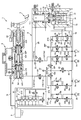
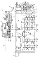
- FIG. 1 is a configuration diagram of a brake control device 1 of Embodiment 1.
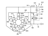
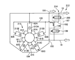
- FIG. 3 is a schematic diagram of a variable displacement pump section 212 of Embodiment 1.
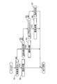
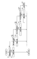
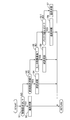
- FIG. It is a flow chart which shows the flow of recirculation valve opening/closing processing according to brake fluid pressure. It is a flow chart which shows the flow of recirculation valve opening/closing processing according to motor current. It is a flow chart which shows the flow of recirculation valve opening/closing processing according to battery voltage.
- 7 is a flowchart showing the flow of a reflux valve opening/closing process according to the amount of heat generated by a motor 211.
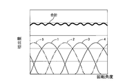
- FIG. 9 is a relationship diagram between a rotation angle of a motor 211 and a discharge amount when there is no cylinder deactivation.
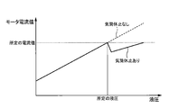
- FIG. 6 is a relationship diagram between a rotation angle of a motor 211 and a discharge amount when cylinders are deactivated. It is a relationship diagram of a hydraulic pressure and a motor current value.
- FIG. 11 is a relationship diagram between the rotation angle of the motor 211 and the discharge amount when the cylinders of the third plunger pump 213C and the fourth plunger pump 213D are deactivated. It is a time chart which shows the operation of the return valve opening/closing processing according to the brake fluid pressure. It is a time chart which shows the operation of the reflux valve opening/closing processing according to the motor current.
- FIG. 7 is a configuration diagram of a brake control device 1 of Embodiment 2.
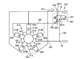
- FIG. 7 is a schematic diagram of a variable displacement pump section 212 of Embodiment 2.
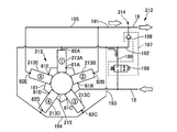
- FIG. 9 is a schematic diagram of a variable displacement pump section 212 of Embodiment 3.
- FIG. It is a schematic diagram of the 2nd state in 3 port switching valve 201.
- 9 is a schematic diagram of a variable displacement pump section 212 of Embodiment 4.
- FIG. It is a principal part enlarged view of the pump 21 of Embodiment 5.
- 9 is a configuration diagram of a brake control device 1 of Embodiment 6.
- FIG. 6 is a configuration diagram of a brake control device 1 of Embodiment 6.
- FIG. 1 is a configuration diagram of a brake control device 1 according to the first embodiment.
- the brake control device 1 is a general vehicle having only an internal combustion engine (engine) as a prime mover for driving the wheels FL to RR, a hybrid vehicle having an electric motor (generator) in addition to the internal combustion engine, and the like. It is mounted on an electric vehicle equipped with only an electric motor.
- the brake control device 1 is installed on each wheel (left front wheel FL, right front wheel FR, left rear wheel RL, right rear wheel RR) as a wheel unit, and depending on the hydraulic pressure of the wheel cylinder (braking force applying unit) 2. It has a working disc brake.
- the brake control device 1 applies a braking force to each of the wheels FL to RR by adjusting the hydraulic pressure of the wheel cylinder 2.
- the brake control device 1 has two systems (primary P system and secondary S system) of brake piping.
- the brake piping type is, for example, the X piping type.
- P system primary system
- S system secondary system
- suffixes P and S are added to the end of the reference numerals.
- suffixes a to d are added to the end of the reference numerals.
- the brake pedal 3 is a brake operation member that receives a driver's brake operation input.
- the push rod 4 makes a stroke according to the operation of the brake pedal 3.
- the master cylinder 5 operates according to the stroke amount of the push rod 4 to generate brake hydraulic pressure (master cylinder hydraulic pressure).
- the master cylinder 5 is replenished with brake fluid from a reservoir tank 6 that stores the brake fluid.
- the master cylinder 5 is a tandem type, and has a primary piston 51P and a secondary piston 51S that stroke according to the stroke of the push rod 4. Both pistons 51P and 51S are arranged in series along the axial direction of the push rod 4.
- the primary piston 51P is connected to the push rod 4.
- the secondary piston 51S is a free piston type.
- a stroke sensor 60 is attached to the master cylinder 5. The stroke sensor 60 detects the stroke amount of the primary piston 51P as the pedal stroke amount of the brake pedal 3.
- Stroke simulator 7 operates according to the driver's brake operation.
- the stroke simulator 7 generates a pedal stroke when the brake fluid flowing out of the master cylinder 5 flows in according to the driver's brake operation.
- the piston 71 of the stroke simulator 7 is axially operated in the cylinder 72 against the biasing force of the spring 73 by the brake fluid supplied from the master cylinder 5. As a result, the stroke simulator 7 generates an operation reaction force according to the driver's brake operation.
- the hydraulic unit 8 can apply braking force to each wheel FL-RR independently of the driver's braking operation.
- the hydraulic unit 8 receives the supply of brake fluid from the master cylinder 5 and the reservoir tank 6.
- the hydraulic unit 8 is installed between the master cylinder 5 and the wheel cylinder 2.
- the hydraulic unit 8 has a motor 211 of a pump (hydraulic pressure source) 21 and a plurality of solenoid valves (cutoff valve 12 and the like) as an actuator for generating a control hydraulic pressure.
- the pump 21 sucks the brake fluid from the reservoir tank 6 and discharges it toward the wheel cylinder 2.
- the pump 21 is, for example, a plunger pump.
- the motor 211 is, for example, a DC brush motor.
- the shutoff valve 12 and the like open and close according to the control signal, and control the flow of the brake fluid by switching the communication state of the fluid passage 11 and the like.
- the hydraulic unit 8 pressurizes the wheel cylinder 2 by the brake hydraulic pressure generated by the pump in a state where the communication between the master cylinder 5 and the wheel cylinder 2 is cut off.
- the hydraulic unit 8 also has hydraulic sensors 35 to 37 for detecting the hydraulic pressure at various places.
- the control unit 9 controls the operation of the hydraulic unit 8.
- the control unit 9 performs information processing according to a built-in program based on the input various information, and calculates a target wheel cylinder hydraulic pressure of the wheel cylinder 2.
- the control unit 9 outputs a command signal to each actuator of the hydraulic unit 8 so that the wheel cylinder hydraulic pressure of the wheel cylinder 2 becomes the target wheel cylinder hydraulic pressure.
- various brake controls boost control, antilock control (ABS), brake control for vehicle motion control, automatic brake control, regenerative cooperative brake control, etc.
- the boost control assists the brake operation by generating a brake fluid pressure that is insufficient with the driver's brake pedal force.
- the anti-lock control suppresses braking slip (lock tendency) of each wheel FL to RR.
- the vehicle motion control is vehicle behavior stabilization control that prevents skidding and the like.
- the automatic brake control is the following vehicle follow-up control, automatic emergency braking, or the like.
- the regenerative cooperative brake control controls the wheel cylinder hydraulic pressure so as to achieve the target deceleration in cooperation with the regenerative brake.
- Both pistons 51P and 51S of the master cylinder 5 are housed in the cylinder 54.
- a primary hydraulic chamber 52P is defined between the pistons 51P and 51S of the master cylinder 5.
- a compression coil spring 53P is installed in the primary hydraulic chamber 52P.
- a secondary hydraulic chamber 52S is defined between the secondary piston 51S and the bottom portion 541 of the cylinder 54.
- a compression coil spring 53S is installed in the secondary hydraulic chamber 52S.
- a liquid passage (connection liquid passage) 11 opens in each of the liquid pressure chambers 52P and 52S.
- Each of the hydraulic chambers 52P and 52S is connected to the hydraulic unit 8 via the liquid passage 11 and can communicate with the wheel cylinder 2.
- the piston 51 strokes when the driver depresses the brake pedal 3, and master cylinder hydraulic pressure is generated as the volume of the hydraulic chamber 52 decreases. Almost the same master cylinder hydraulic pressure is generated in both hydraulic chambers 52P and 52S.
- the brake fluid is supplied from the fluid pressure chamber 52 to the wheel cylinder 2 via the fluid passage 11.
- the master cylinder 5 pressurizes the wheel cylinders 2a, 2d of the P system by the master cylinder hydraulic pressure generated in the primary hydraulic chamber 52P via the liquid path of the P system (liquid path 11P). Further, the master cylinder 5 pressurizes the wheel cylinders 2b, 2c of the S system via the liquid path of the S system (liquid path 11S) by the master cylinder hydraulic pressure generated in the secondary hydraulic chamber 52S.
- the stroke simulator 7 has a cylinder 72, a piston 71, a spring 73 and a damper 74.
- the cylinder 72 has a cylindrical inner peripheral surface.
- the cylinder 72 has a piston housing portion 721 and a spring housing portion 722.
- the piston housing 721 has a smaller diameter than the spring housing 722.
- a liquid passage 27, which will be described later, is always open on the inner peripheral surface of the spring accommodating portion 722.
- the piston 71 is movable in the piston housing portion 721 in the axial direction.
- the piston 71 separates the inside of the cylinder 72 into a positive pressure chamber 711 and a back pressure chamber 712.
- the liquid passage 26 is always open to the positive pressure chamber 711.
- the liquid passage 27 always opens in the back pressure chamber 712.
- a piston seal 75 is installed on the outer circumference of the piston 71.
- the piston seal 75 is in sliding contact with the inner peripheral surface of the piston housing portion 721 and seals between the inner peripheral surface of the piston housing portion 721 and the outer peripheral surface of the piston 71.
- the piston seal 75 is a separation seal member that liquid-tightly separates the positive pressure chamber 711 and the back pressure chamber 712 by sealing them, and complements the function of the piston 71.
- the spring 73 is a compression coil spring installed in the back pressure chamber 712, and biases the piston 71 from the back pressure chamber 712 side toward the positive pressure chamber 711 side.
- the spring 73 generates a reaction force according to the amount of compression.
- the spring 73 is arranged between the piston 71 and the retainer member 78.
- the damper 74 is an elastic member such as rubber and is formed in a cylindrical shape.
- the damper 74 is arranged between the retainer member 78 and the plug member 76 that closes the spring accommodating chamber 722.
- a stopper member 77 is fixed to the retainer member 78.
- the stroke simulator 7 operates when the brake fluid flows into the positive pressure chamber 711 in response to the driver's braking operation, and when a fluid pressure above a predetermined level (master cylinder fluid pressure) acts on the pressure receiving surface of the piston 71 in the positive pressure chamber 711. 71 moves toward the back pressure chamber 712 side while compressing the spring 73 and the damper 74. At this time, the volume of the positive pressure chamber 711 increases and at the same time the volume of the back pressure chamber 712 decreases. As a result, the brake fluid flowing out from the secondary hydraulic chamber 52S flows into the positive pressure chamber 711, and at the same time, the brake fluid flows out from the back pressure chamber 712 and the brake fluid in the back pressure chamber 712 is discharged. When the pressure in the positive pressure chamber 711 decreases below a predetermined value, the piston 71 returns to the initial position by the biasing force of the spring 73 and the damper 74.
- a fluid pressure above a predetermined level master cylinder fluid pressure
- the hydraulic unit 8 has a housing 8a.
- the housing 8a has a plurality of liquid passages (such as the liquid passage 11).
- the pump 21, the motor 211, and the plurality of solenoid valves (such as the shutoff valve 12) are fixed to the housing 8a.
- the fluid passage 11 connects between the fluid pressure chamber 52 of the master cylinder 5 and the wheel cylinder 2.
- the liquid passage 11P branches into a liquid passage 11a and a liquid passage 11d.
- the liquid passage 11S branches into a liquid passage 11b and a liquid passage 11d.
- the shutoff valve (solenoid valve) 12 is a normally open (propagated in a non-energized state) electromagnetic proportional valve provided in the liquid passage 11.
- the solenoid proportional valve can realize any opening according to the current supplied to the solenoid.
- the liquid passage 11 is separated by a shutoff valve 12 into a liquid passage 11A on the master cylinder 5 side and a liquid passage 11B on the wheel cylinder 2 side.
- the solenoid-in valve 13 is a normally open solenoid proportional valve provided on the wheel cylinder 2 side (liquid paths 11a to 11d) of the shutoff valve 12 in the liquid path 11 and corresponding to each wheel FL to RR.
- a bypass liquid passage 14 that bypasses the solenoid-in valve 13 is provided in the liquid passage 11.
- a check valve 15 is provided in the bypass liquid passage 14. The check valve 15 allows only the flow of brake fluid from the wheel cylinder 2 side to the master cylinder 5 side.
- the suction pipe 16 connects the reservoir tank 6 and the internal reservoir 17 formed in the housing 8a.
- the liquid passage (suction liquid passage) 18 connects the internal reservoir 17 and the suction side of the pump 21.
- the liquid passage (discharge liquid passage) 19 connects the discharge side of the pump 21 and the cutoff valve 12 and the solenoid-in valve 13 in the liquid passage 11B.
- the liquid passage 19 branches into a liquid passage 19P of the P system and a liquid passage 19S of the S system. Both liquid paths 19P and 19S are connected to the liquid paths 11P and 11S. Both liquid passages 19P and 19S function as a communication passage that connects the liquid passages 11P and 11S to each other.
- the communication valve 20 is a normally closed (closed in a non-energized state) on/off valve provided in the liquid passage 19. The opening/closing of the on/off valve is binary-switched according to the current supplied to the solenoid.
- the pump 21 generates a hydraulic pressure in the hydraulic passage 11 by the brake fluid supplied from the reservoir tank 6 to generate a wheel cylinder hydraulic pressure.
- the pump 21 is connected to the wheel cylinders 2a to 2d via the liquid passage 19 and the liquid passages 11P and 11S, and pressurizes the wheel cylinder 2 by discharging the brake fluid to the liquid passage 19. Details of the pump 21 will be described later.
- the liquid passage 22 connects the branch point of both the liquid passages 19P and 19S and the liquid passage 23.
- a pressure regulating valve 24 is provided in the liquid passage 22.
- the pressure regulating valve 24 is a normally open solenoid proportional valve.
- the liquid path 23 connects the wheel cylinder 2 side of the liquid path 11B with respect to the solenoid-in valve 13 and the internal reservoir 17.
- the solenoid-out valve 25 is a normally closed on/off valve provided in the liquid passage 23.
- the liquid passage 26 branches from the liquid passage 11A of the P system and is connected to the positive pressure chamber 711 of the stroke simulator 7.
- the liquid passage 26 may directly connect the primary hydraulic chamber 52P and the positive pressure chamber 711 without the liquid passage 11P (11A).
- the liquid passage 27 connects the back pressure chamber 712 of the stroke simulator 7 and the liquid passage 11P (11A). Specifically, the liquid passage 27 branches from between the shutoff valve 12P and the solenoid-in valve 13 in the liquid passage 11P (11B) to connect to the back pressure chamber 712.
- the stroke simulator-in valve 28 is a normally closed on/off valve provided in the liquid passage 27.
- the liquid passage 27 is separated by a stroke simulator-in valve 28 into a liquid passage 27A on the back pressure chamber 712 side and a liquid passage 27B on the liquid passage 11 side.
- a bypass liquid passage 29 is provided in parallel with the liquid passage 27.
- the bypass liquid passage 29 connects between the liquid passage 27A and the liquid passage 27B.
- a check valve 30 is provided in the bypass liquid passage 29.
- the check valve 30 allows the flow of the brake fluid from the fluid passage 27A toward the fluid passage 11 (27B) side and suppresses the flow of the brake fluid in the opposite direction.
- the liquid passage 31 connects the back pressure chamber 712 of the stroke simulator 7 and the liquid passage 23.
- the stroke simulator out valve 32 is a normally closed on/off valve provided in the liquid passage 31. Bypassing the stroke simulator out valve 32, a bypass liquid passage 33 is provided in parallel with the liquid passage 31.
- a check valve 34 is provided in the bypass liquid passage 33. The check valve 34 allows the flow of the brake fluid from the fluid passage 23 side toward the back pressure chamber 712 side and suppresses the brake fluid flow in the opposite direction.
- a master cylinder hydraulic pressure sensor 35 that detects the hydraulic pressure at this location is provided between the shutoff valve 12P and the master cylinder 5 in the hydraulic passage 11P (fluid path 11A).
- a wheel cylinder fluid pressure sensor (P system pressure sensor, S system pressure sensor) 36 for detecting the fluid pressure (wheel cylinder fluid pressure) at this location is provided between the shutoff valve 12 and the solenoid-in valve 13 in the fluid path 11. It is provided.
- a discharge pressure sensor 37 is provided between the discharge side of the pump 21 and the communication valve 20 in the liquid path 19 to detect the liquid pressure at this location (pump discharge pressure).
- the brake system (fluid path 11) connecting the hydraulic chamber 52 of the master cylinder 5 and the wheel cylinder 2 constitutes the first system.
- This first system can realize pedaling brake (non-boosting control) by generating wheel cylinder hydraulic pressure by master cylinder hydraulic pressure generated by using pedaling force.
- the brake system (the liquid passage 19, the liquid passage 22, the liquid passage 23, etc.) that includes the pump 21 and connects the reservoir tank 6 and the wheel cylinder 2 is the second system.
- This second system constitutes a so-called brake-by-wire device that generates wheel cylinder hydraulic pressure by the hydraulic pressure generated by using the pump 21, and realizes boost control etc. as brake-by-wire control. It is possible.
- the stroke simulator 7 generates an operation reaction force associated with the driver's braking operation.
- the pump 21 of the first embodiment includes a motor 211 and a variable displacement pump section 212.
- the variable displacement pump unit 212 is of a variable displacement type, that is, it can change the discharge amount of the brake fluid per one rotation of the motor 211, and has a constant displacement pump unit 213 and an adjustment mechanism 214.
- the constant volume pump unit 213 has a constant discharge amount of the brake fluid per one rotation of the motor 211.
- the adjusting mechanism 214 realizes a variable capacity by adjusting the discharge amount of the brake fluid discharged from the constant volume pump unit 213.
- FIG. 2 is a schematic diagram of the variable displacement pump unit 212 according to the first embodiment.
- the constant capacity pump unit 213 has five cylinder plunger pumps (a plurality of constant capacity pumps) 213A to 213E.
- the plunger pumps 213A to 213E are housed in five cylinder housing holes formed in the housing 8a.
- Each of the plunger pumps 213A to 213E has a first plunger pump (first plunger pump) 213A, a second plunger pump (second plunger pump) 213B, in a direction (circumferential direction) around the rotation axis of the motor 211.
- the third plunger pump (third plunger pump) 213C, the fourth plunger pump 213D, and the fifth plunger pump (fourth plunger pump) 213E are arranged in this order at equal intervals (72 degrees (360 degrees/5 pieces)).
- Each cylinder accommodating hole is connected to a cam chamber in which the eccentric cam 215 is accommodated.
- the eccentric cam 215 is fixed to the rotation shaft of the motor 211 and is rotated by the rotation drive of the motor 211.
- the eccentric cam 215 overlaps with the operation axis of each of the plunger pumps 213A to 213E in the direction of the rotation axis of the motor 211.
- the adjusting mechanism 214 includes a liquid passage (first discharge liquid passage) 191, a liquid passage (second discharge liquid passage) 192, a liquid passage (third discharge liquid passage) 193, a liquid passage 194, a liquid passage (fourth discharge liquid passage).
- Liquid discharge path) 195 a liquid path (reflux liquid path) 196, and an adjusting unit 197.
- the suction portions 81A to 81E of the plunger pumps 213A to 213E communicate with each other via the liquid passage 181 and are connected to the liquid passage 18.
- the liquid passage 191 connects the discharge portion 82A of the first plunger pump 213A and the liquid passage 19.
- the liquid passage 192 connects the discharge portion 82B of the second plunger pump 213B and the liquid passage 19.
- the liquid passage 193 connects the discharge portion 82C of the third plunger pump 213C and the liquid passage 191.
- the liquid passage 194 connects the discharge portion 82D of the fourth plunger pump 213D and the liquid passage 193.
- the liquid passage 195 connects the discharge portion 82E of the fifth plunger pump 213E and the liquid passage 192.
- the liquid passage 196 branches from the liquid passage 192 and is connected to the liquid passage 18.
- the adjusting unit 197 supplies the brake fluid discharged from the second plunger pump 213B and the fifth plunger pump 213E to the liquid passage 19 via the liquid passage 192 and the flow amount to the reservoir tank 6 via the liquid passage 196. And can be adjusted.
- the adjusting unit 197 has a check valve 198 and a return valve 199.
- the check valve 198 is provided in the liquid passage 192 and allows only the flow of the brake fluid from the discharge portions 82B, 82E side to the liquid passage 19 side.
- the reflux valve 199 is a normally closed on
- the brake fluid that has flowed out from the discharge portions 82A, 82C, 82D of the first plunger pump 213A, the third plunger pump 213C, and the fourth plunger pump 213D merges in the fluid passage 191. After that, it is sent from the liquid path 19 to the liquid path 11. Further, the brake fluid that has flowed out from the discharge portions 82B and 82E of the second plunger pump 213B and the fifth plunger pump 213E joins in the fluid passage 192.
- the return valve 199 when the return valve 199 is operated in the opening direction, the liquid passage 192 is in communication with the liquid passage 18, and the pressure of the liquid passage 192 ( ⁇ atmospheric pressure) is lower than the pressure of the liquid passage 19.
- the check valve 198 remains closed, and the brake fluid in the fluid passage 192 passes through the fluid passage 196 and the fluid passage 18 and is returned to the suction portions 81B and 81E. That is, by opening the return valve 199, the discharge portions 82B, 82E and the suction portions 81B, 81E of the second plunger pump 213B and the fifth plunger pump 213E are connected, so the second plunger pump 213B and the fifth plunger pump 213B.
- the adjusting unit 197 of the first embodiment includes a flow path for sending the brake fluid discharged from the second plunger pump 213B and the fifth plunger pump 213E to the liquid passage 19 via the liquid passage 192, and a reservoir via the liquid passage 196. It is a switching unit that switches between the flow path to be sent to the tank 6.
- the control unit 9 switches the state without cylinder deactivation and the state with cylinder deactivation by controlling the return valve 199 according to a predetermined condition.
- a specific method of controlling the return valve 199 by the control unit 9 will be described.
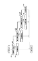
- FIG. 3 is a flowchart showing the flow of the return valve opening/closing processing according to the brake fluid pressure. This process is repeatedly executed at a predetermined calculation cycle.
- step S1 it is determined whether there is a braking request. If YES, the process proceeds to step S2, and if NO, the process proceeds to step S3.
- the braking request includes a request for a brake operation by the driver as well as a request for automatic brake control without the driver's intention.
- the return valve 199 is operated in the valve closing direction.
- step S3 it is determined whether the return valve 199 was operating in the valve opening direction in the previous calculation cycle. If YES, the process proceeds to step S4, and if NO, the process proceeds to step S5.
- the determination in step S3 is to maintain the cylinder deactivated state until the end of braking when the cylinder deactivated operation is performed during one braking.
- the pump discharge pressure ⁇ brake hydraulic pressure
- the pump discharge pressure is the wheel on the dry road surface. It is possible to suppress sound vibration due to repeated opening and closing of the return valve 199 when there is a pressure request around the predetermined hydraulic pressure P1 corresponding to the lock pressure (for example, about 9 MPa).
- step S4 the return valve 199 is operated in the valve opening direction.
- step S5 it is determined whether the pump discharge pressure detected by the discharge pressure sensor 37 is equal to or higher than the predetermined hydraulic pressure P1. If YES, the process proceeds to step S6, and if NO, the process proceeds to step S7.
- the determination in step S5 is to carry out the cylinder deactivation at a pressure higher than the response required (for example, the wheel lock pressure on the dry road surface), and the response is emphasized until the predetermined fluid pressure P1. Do not pause.
- step S6 the return valve 199 is operated in the valve opening direction.
- step S7 the return valve 199 is operated in the valve closing direction.
- FIG. 4 is a flowchart showing the flow of the return valve opening/closing processing according to the motor current. It should be noted that steps that perform the same processing as the steps shown in FIG. 3 are assigned the same step numbers and description thereof is omitted.
- step S8 it is determined whether the motor has just started. If YES, the process proceeds to step S9, and if NO, the process proceeds to step S10. Immediately after starting the motor, the judgment in step S8 is often performed with high torque to improve the responsiveness of the rotation speed, and high current is likely to occur even under low load (low pressure). The purpose is not to carry out suspension.
- step S9 the return valve 199 is operated in the valve closing direction.
- step S10 it is determined whether the motor terminal current is equal to or greater than a predetermined current value I1. If YES, the process proceeds to step S6, and if NO, the process proceeds to step S7.
- the determination in step S10 is for performing cylinder deactivation when it is assumed that the load (pressure) is equal to or higher than the pressure required for responsiveness (for example, wheel lock pressure on a dry road surface), and the predetermined current Cylinder deactivation is not performed with emphasis on responsiveness up to the value I1.
- the pump discharge pressure is the predetermined hydraulic pressure P1. That is, the predetermined current value I1 is the motor terminal current corresponding to the wheel lock pressure on the dry road surface.
- FIG. 5 is a flow chart showing the flow of the return valve opening/closing processing according to the battery voltage.
- step S11 it is determined whether the battery voltage of the vehicle-mounted battery that supplies electric power to the motor 211 is equal to or lower than a predetermined voltage value V1. If YES, the process proceeds to step S6, and if NO, the process proceeds to step S7.
- the determination in step S11 is for carrying out cylinder deactivation when the battery voltage drops and output limitation (including current limitation) is required.
- FIG. 6 is a flowchart showing the flow of the return valve opening/closing processing according to the heat generation amount of the motor 211. It should be noted that steps that perform the same processing as the steps shown in FIG. 3 are assigned the same step numbers and description thereof is omitted.
- step S12 it is determined whether the heat generation amount (temperature) of the motor 211 is equal to or higher than a predetermined amount (predetermined temperature) H1. If YES, the process proceeds to step S6, and if NO, the process proceeds to step S7.
- the determination in step S12 is for performing cylinder deactivation when limiting the current for reducing heat generation of the motor 211 during overload operation by repeating high load operation.
- the brake control device 1 lowers the discharge amount of the pump 21 by suspending the two-cylinder plunger pumps 213B and 213E among the five-cylinder plunger pumps 213A to 213E when the load is high. Suppresses an increase in power consumption of the motor 211.
- FIG. 7 is a relationship diagram between the rotation angle and the discharge amount of the motor 211 without cylinder deactivation
- FIG. 8 is a relationship diagram between the rotation angle and the discharge amount of the motor 211 with cylinder deactivation.
- 1 corresponds to the first plunger pump 213A
- 2 corresponds to the second plunger pump 213B
- 3 corresponds to the third plunger pump 213C
- 4 corresponds to the fourth plunger pump 213D
- 5 corresponds to the fifth plunger pump 213E.
- the total discharge amount is 5 cylinders. Since the load torque is proportional to the total discharge amount, the load torque is always maintained at a high value.
- the total discharge amount is reduced by the amount of deactivation of two cylinders, so the load torque is reduced to 3/5 compared to the case without cylinder deactivation except for the no-load torque (current).
- FIG. 9 is a relationship diagram between the hydraulic pressure and the motor current value.
- the motor current value increases at a constant gradient as the hydraulic pressure increases.
- the motor current value once decreases due to cylinder deactivation, and then with a smaller gradient (3/5 times) than without cylinder deactivation. Gradient). Therefore, when the cylinder is deactivated, the motor current value can be made smaller than when the cylinder is deactivated, and the increase in power consumption can be suppressed.
- the motor 211 can be reduced in size and weight, and the heat dissipation structure in the control unit 9 can be simplified, so that cost reduction and reduction in size and weight of the brake control device 1 can be realized.
- the second plunger pump 213B and the fifth plunger pump 213E which deactivate the cylinder when the load is high, are arranged so as not to be adjacent to each other in the circumferential direction.
- FIG. 10 is a relationship diagram between the rotation angle of the motor 211 and the discharge amount when the cylinders of the third plunger pump 213C and the fourth plunger pump 213D are deactivated.
- the third plunger pump 213C and the fourth plunger pump 213D are adjacent to each other in the circumferential direction. Therefore, when the cylinders are deactivated, the load torques generated in the plunger pumps 213A, 213B, and 213E of the remaining three cylinders that continue to discharge are unevenly input to the eccentric cam 215 in the circumferential direction.
- the fluctuation range of the load torque generated during one rotation of the motor 211 becomes large, resulting in deterioration of quietness.
- the load torque generated in the plunger pumps 213A, 213C, and 213D of the remaining three cylinders that continue to discharge the load torque with respect to the eccentric cam 215. Input approximately evenly in the circumferential direction.
- the discharge timing of each plunger pump 213A, 213C, 213D is divided into approximately three equal parts by one rotation of the motor 211, as shown in FIG. It is possible to suppress the accompanying deterioration of quietness.
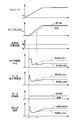
- FIG. 11 is a time chart showing the action of the reflux valve opening/closing processing according to the brake fluid pressure.
- the specific discharge amount of the pump 21 decreases from 5 cylinders to 3 cylinders, so the pressure regulating valve 24 is operated in the closing direction as compared with the case of 5 cylinders, and the leak amount of the brake fluid from the fluid passage 22 is adjusted. By doing so, the target wheel cylinder hydraulic pressure is realized.
- the frequency of operation under a high load where the pump discharge pressure exceeds the predetermined hydraulic pressure P1 is low, if the specifications of the motor 211 and the control unit 9 are determined so as to satisfy the maximum generated hydraulic pressure (for example, about 17 MPa) required by the system.
- the load is low (normal operation range), which accounts for most of the operation frequency, it becomes over-spec.
- the cylinder deactivation is performed to suppress the motor current at the time of high load, and the excessive motor output becomes unnecessary. Therefore, it is possible to suppress an increase in power consumption more than necessary.
- FIG. 12 is a time chart showing the operation of the reflux valve opening/closing processing according to the motor current.
- FIG. 13 is a time chart showing the operation of the reflux valve opening/closing processing according to the battery voltage.
- the recirculation valve 199 is actuated in the opening direction, and at this time, the two-cylinder plunger pumps 213B and 213E are stopped.
- the target wheel cylinder hydraulic pressure is realized by operating the pressure regulating valve 24 in the valve closing direction as compared with the case of 5 cylinders and adjusting the leak amount of the brake fluid.
- the pump 21 may not be sufficiently operated because the load torque is large.
- the plunger pumps 213B and 213E are stopped, the driving torque becomes small, so that the operation of the pump 21 can be continued. In other words, the brake control can be continued without stopping the pump 21 by deactivating the cylinder when the current is limited.
- the first embodiment has the following effects.
- the variable displacement pump section 212 has five-cylinder plunger pumps 213A to 213E, and the operation of each plunger pump 213A to 213E can be selectively switched according to a predetermined condition. Therefore, the discharge amount of the brake fluid per one rotation of the motor 211 changes depending on the number of plunger pumps that operate, so that a variable displacement can be realized by using a plunger pump that is a constant displacement pump.
- the variable displacement pump unit 212 adjusts the constant displacement pump unit 213 in which the discharge amount of the brake fluid per one rotation of the motor 211 is constant and the discharge amount of the brake fluid discharged from the constant displacement pump unit 213. And an adjusting mechanism 214 for adjusting. Therefore, a variable displacement can be realized by using a constant displacement pump.
- the constant capacity pump unit 213 has a first plunger pump 213A and a second plunger pump 213B. Therefore, the variable displacement can be realized by using the two plunger pumps 213A and 213B which are constant displacement pumps.
- the adjusting mechanism 214 includes the liquid passage 191 that connects the discharge portion 82A of the first plunger pump 213A and the liquid passage 19, and the discharge portion 82B of the second plunger pump 213B and the liquid passage 19.
- the liquid passage 192, the liquid passage 196 branched from the liquid passage 192 and connected to the liquid passage 18, and the brake fluid discharged from the discharge portion 82B of the second plunger pump 213B are supplied to the liquid passage 19 via the liquid passage 192.
- An adjusting unit 197 that can adjust the flow rate to be sent and the flow rate to be sent to the reservoir tank 6 via the liquid path 196 is provided. Therefore, since the adjusting unit 197 can adjust the discharge amount of the second plunger pump 213B, a variable capacity can be realized.
- the adjusting unit 197 supplies the brake fluid discharged from the discharge unit 82B of the second plunger pump 213B to the liquid passage 19 via the liquid passage 192 and the reservoir tank 6 via the liquid passage 196. It is a switching unit for switching between the flow path and the flow path. Therefore, the discharge amount of the second plunger pump 213B can be changed to a predetermined amount or zero by switching the flow path.
- the switching unit (adjustment unit 197) is provided in the liquid passage 192, and is provided in the liquid passage 196 and the check valve 198 that allows only the flow from the discharge portion 82B of the second plunger pump 213B to the liquid passage 19. And a recirculation valve 199. Therefore, by opening/closing the return valve 199, the flow path of the brake fluid discharged from the second plunger pump 213B can be switched.
- the control unit 9 for controlling the pump 21 is provided. The control unit 9 controls the wheel when the pump discharge pressure ( ⁇ the brake hydraulic pressure generated in the wheel cylinder 2) exceeds the predetermined hydraulic pressure P1 or the predetermined hydraulic pressure P1.
- the pump 21 is controlled so as to reduce the flow rate of the brake fluid supplied to the fluid passage 11 as compared with the case where the brake fluid pressure generated in the cylinder 2 is lower than the predetermined fluid pressure P1. Therefore, the motor current at the time of high load is suppressed, and the increase in power consumption can be suppressed.
- the control unit 9 for controlling the pump 21 is provided.When the current between the terminals of the motor 211 exceeds the predetermined current value I1 or the predetermined current value I1, the control unit 9 controls the current between the terminals of the motor 211 to the predetermined current value.
- the pump 21 is controlled so as to reduce the flow rate of the brake fluid supplied to the fluid passage 11 as compared with the case where the flow rate is lower than I1. Therefore, the motor current at the time of high load is suppressed, and the increase in power consumption can be suppressed.
- the control unit 9 for controlling the pump 21 is provided, and the control unit 9 controls the battery voltage when the battery voltage is lower than the predetermined voltage value V1 or the predetermined voltage value V1, as compared to when the battery voltage exceeds the predetermined voltage value V1.
- the pump 21 is controlled so as to reduce the flow rate of the brake fluid supplied to the fluid passage 11. Therefore, it is possible to prevent the brake control function from being limited (the pump 21 is stopped) even when the current is limited.
- the control unit 9 for controlling the pump 21 is provided.When the heat generation amount of the motor 211 is the predetermined amount H1 or exceeds the predetermined amount H1, the heat generation amount of the motor 211 is lower than the predetermined amount H1.
- the pump 21 is controlled so as to reduce the flow rate of the brake fluid supplied to the fluid passage 11 as compared with the above. Therefore, heat generation of the motor 211 is suppressed, and an excessive temperature rise can be suppressed. As a result, the heat dissipation structure of the control unit 9 can be simplified, so that the brake control device 1 can be reduced in cost and reduced in size and weight.
- the constant-volume pump unit 213 has a third plunger pump 213C and a fifth plunger pump 213E, and the adjusting mechanism 214 connects the discharge unit 82C of the third plunger pump 213C and the liquid passage 191. It has a liquid passage 193 for connection, a discharge portion 82E of the fifth plunger pump 213E, and a liquid passage 195 for connecting the liquid passage 192. Therefore, a variable displacement can be realized by using the four plunger pumps 213A to 213C and 213E which are constant displacement pumps.
- the first plunger pump 213A, the second plunger pump 213B, the third plunger pump 213C, and the fifth plunger pump 213E are arranged in this order in the direction around the rotation axis of the motor 211. Therefore, since the plunger pumps 213B and 213E that deactivate the cylinders are not adjacent to each other in the circumferential direction of the rotation axis of the motor 211, the load torque generated during one rotation of the motor 211 when the plunger pumps 213B and 213E are deactivated. The fluctuation range of can be reduced, and the deterioration of quietness due to cylinder deactivation can be suppressed.
- a shutoff valve 12 provided in the liquid passage 11 is provided, the liquid passage 11 connects the master cylinder 5 and the wheel cylinder 2, and the variable displacement pump section 212 is a shutoff valve in the liquid passage 11. Brake fluid is supplied to the fluid path between 12 and the wheel cylinder 2. Therefore, it is possible to suppress an increase in power consumption in the brake-by-wire control.
- FIG. 14 is a configuration diagram of the brake control device 1 of the second embodiment
- FIG. 15 is a schematic diagram of the variable displacement pump unit 212 of the second embodiment.
- the adjusting unit 197 of the second embodiment has a return valve 199 and a shutoff valve 200.
- the shutoff valve 200 is a normally open type on/off valve provided in the liquid path 192.
- the control unit 9 operates the shutoff valve 200 in the opening direction when operating the return valve 199 in the closing direction. As a result, the brake fluid in the fluid passage 192 is sent from the fluid passage 19 to the fluid passage 11.
- the control unit 9 operates the shutoff valve 200 in the closing direction when operating the return valve 199 in the opening direction. As a result, the communication between the liquid passage 192 and the liquid passage 19 is cut off, so that the brake fluid in the liquid passage 192 is returned from the liquid passage 196 to the liquid passage 18.
- control unit 9 operates the return valve 199 in the valve opening direction and the shutoff valve 200 in the valve closing direction in the scene where the pressure reduction response is required.
- a motor having a large inertia such as a DC brush motor is adopted as the motor 211
- the pressure regulating valve 24 alone may not be able to sufficiently reduce the pressure in a scene where pressure reduction responsiveness is required.
- By performing the cylinder deactivation in a scene where the pressure reduction response is required it is possible to reduce the discharge amount of the pump 21 and improve the pressure reduction response.
- the return valve 199 and the shutoff valve 200 as an electromagnetic proportional valve, the flow rate of the brake fluid in the fluid passages 192 and 196 can be freely adjusted.
- both the return valve 199 and the shutoff valve 200 are electromagnetic proportional valves, and the opening degree is gradually changed at the start and end of the cylinder deactivation, whereby it is possible to suppress the occurrence of an oil hammer noise due to a sudden change in the pump discharge pressure.
- the adjusting unit 197 includes the shutoff valve 200 provided in the liquid passage 192 and the return valve 199 provided in the liquid passage 196. Therefore, by opening/closing the shutoff valve 200 and the return valve 199, the flow path of the brake fluid discharged from the second plunger pump 213B can be switched. Further, since the shutoff valve 200 can be opened and closed at any timing, the air bleeding property of the second plunger pump 213B and the fifth plunger pump 213E is improved, and the failure diagnosis of the return valve 199 is facilitated.
- FIG. 16 is a schematic diagram of the variable displacement pump unit 212 according to the third embodiment.
- the adjusting unit (switching unit) 197 of the third embodiment has a 3-port switching valve 201.
- the 3-port switching valve 201 is a 3-port 2-position valve having a supply port 2011, an output port 2012 and an exhaust port 2013.
- the supply port 2011 is connected to the liquid passage 192
- the output port 2012 is connected to the liquid passage 191
- the exhaust port 2013 is connected to the liquid passage 196.
- the 3-port switching valve 201 has a first state shown in FIG. 16 and a first state shown in FIG.
- the adjusting unit 197 is a three-port switching valve 201 that switches the communication state between the liquid passage 192 and the liquid passage 19 and the communication state between the liquid passage 192 and the reservoir tank 6. Therefore, by switching the state of the 3-port switching valve 201, the discharge amount of the second plunger pump 213B can be changed to a predetermined amount or zero. Further, since the number of parts can be reduced with respect to the adjusting unit 197 of the first and second embodiments, it is possible to reduce the cost and size and weight of the brake control device 1.
- FIG. 18 is a schematic diagram of the variable displacement pump section 212 of the fourth embodiment.
- the liquid passage 191 connects the discharge portion 82B of the second plunger pump 213B and the liquid passage 19.
- the liquid passage 192 connects the discharge portion 82A of the first plunger pump 213A and the liquid passage 19.
- the liquid passage 193 connects the discharge portion 82C of the third plunger pump 213C and the liquid passage 192.
- the liquid passage 194 connects the discharge portion 82D of the fourth plunger pump 213D and the liquid passage 193.
- the liquid passage 195 connects the discharge portion 82E of the fifth plunger pump 213E and the liquid passage 191.
- the adjusting unit 197 supplies the brake fluid discharged from the first plunger pump 213A, the third plunger pump 213C, and the fourth plunger pump 213D to the liquid passage 19 via the liquid passage 192 and the liquid passage 196.
- the flow rate sent to the reservoir tank 6 can be adjusted.
- the brake control device 1 of the fourth embodiment when the return valve 199 is operated in the valve opening direction, the first plunger pump 213A, the third plunger pump 213C and the fourth plunger pump 213D are in the cylinder deactivated state. Therefore, compared to the configuration of the first embodiment, the number of plunger pumps in which the cylinders are deactivated is large, so that the motor current at high load can be further reduced.
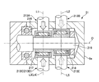
- FIG. 19 is an enlarged view of a main part of the pump 21 according to the fifth embodiment.
- Two eccentric cams 217 and 218 are housed in the cam chamber 216 of the housing 8a.
- the two eccentric cams 217 and 218 are aligned in the direction of the rotation axis O of the motor 211 and are fixed to the rotation shaft 219 of the motor 211.
- the second eccentric cam 218 is arranged so as to face the motor 211 with the first eccentric cam 217 interposed therebetween.
- the first eccentric cam 217 overlaps the operating axes L1, L3, L4 of the first plunger pump 213A, the third plunger pump 213C and the fourth plunger pump 213D, and the second eccentric cam 218 is It overlaps with the operating axes L2 and L5 of the second plunger pump 213B and the fifth plunger pump 213E.
- the first plunger pump 213A, the third plunger pump 213C, and the fourth plunger pump 213D are arranged at equal intervals (120° pitch) in the circumferential direction, and the second plunger pump 213B and the fifth plunger pump 213E are arranged facing each other in the circumferential direction. (180° pitch).
- the rotary shaft 219 of the motor 211 receives bending moment from each of the plunger pumps 213A to 213E. Since the second eccentric cam 218 is located closer to the tip side of the rotary shaft 219 than the first eccentric cam 217 (far from the motor 211), the bending moment received at the position of the second eccentric cam 218 is the first eccentric cam 218. It is larger than the bending moment at the position of 217. Therefore, in the fifth embodiment, the plunger pumps 213B and 213E for deactivating the cylinder are configured to be operated by the second eccentric cam 218 of the two rows of the eccentric cams 217 and 218 that is farther from the motor 211.
- the number of plunger pumps assigned to the first eccentric cam 217 and the second eccentric cam 218 is not limited to the above-described 3 cylinders and 2 cylinders, and may be 3 cylinders and 3 cylinders or 2 cylinders and 2 cylinders. .. Also, the circumferential distance between the cylinders at that time may be arbitrarily set, such as 120 degrees or 180 degrees, depending on the number of cylinders.
- the first eccentric cam 217 that overlaps with the operation axis L1 of the first plunger pump 213A in the direction of the rotation axis O of the motor 211 and the motor 211 that sandwiches the first eccentric cam 217 in the direction of the rotation axis O of the motor 211.
- a second eccentric cam 218 that is disposed so as to face the operating axis L2 of the second plunger pump 213B. Therefore, the bending moment that acts on the rotating shaft 219 of the motor 211 when the cylinder is deactivated can be relaxed, and the durability of the second eccentric cam 218 can be improved.
- FIG. 20 is a configuration diagram of the brake control device 1 according to the sixth embodiment.
- the pump 21 of the sixth embodiment has a motor 211 and a variable displacement pump section 220.
- the variable displacement pump section 220 is a known variable displacement pump in which the discharge amount of the brake fluid per one rotation of the motor 211 can be changed according to a command from the control unit 9. Therefore, when the load is high, the discharge amount of the variable displacement pump section 220 is reduced as compared with the case where the load is low, so that the motor current at the time of high load can be suppressed and an increase in power consumption can be suppressed.
- the embodiment for carrying out the present invention has been described above, but the specific configuration of the present invention is not limited to the configuration of the embodiment, and there are design changes and the like within the scope not departing from the gist of the invention. Are also included in the present invention.
- the present invention can be applied to a brake control device in a brake-by-wire device in which a master cylinder and a wheel cylinder are not connected by a liquid path, and has the same effects as the embodiment. At least two plunger pumps may be used.
- the cylinder deactivation may be performed when the load is low, and the cylinder deactivation may be terminated when a high response and a large flow rate are required.
- the brake control device includes a connection fluid passage connected to a braking force application unit that applies a braking force to wheels according to the brake fluid pressure, and a hydraulic pressure source that supplies the brake fluid to the connection fluid passage.
- the hydraulic pressure source includes a motor and a variable displacement pump unit capable of changing a discharge amount of the brake fluid per one rotation of the motor.
- the variable displacement pump section has a plurality of constant displacement pumps, and the plurality of constant displacement pumps are selectively switched and operated according to a predetermined condition.
- variable displacement pump unit is a constant displacement pump unit in which the discharge amount of the brake fluid per one rotation of the motor is a constant amount, and the variable displacement pump unit discharges from the constant displacement pump unit. And an adjusting mechanism for adjusting the discharged amount of the brake fluid.
- the constant displacement pump section includes a first plunger pump and a second plunger pump.
- a discharge liquid passage that connects the connection liquid passage and a discharge side of the variable displacement pump unit, a reservoir tank, and a suction side of the variable displacement pump unit. And a suction liquid passage connecting the discharge mechanism of the first plunger pump and the discharge liquid passage, the first discharge liquid passage connecting the discharge unit of the first plunger pump and the discharge liquid passage, A second discharge liquid passage connecting the discharge portion of the plunger pump and the discharge liquid passage, a reflux liquid passage branched from the second discharge liquid passage and connected to the suction liquid passage, and the second discharge liquid passage.
- the adjusting section is configured to cause the flow path of the brake fluid discharged from the discharge section of the second plunger pump to pass through the second discharge fluid path.
- a switching unit that switches between a flow path for sending to the discharge liquid path and a flow path for sending to the reservoir tank via the reflux liquid path.
- the switching unit is provided in the second discharge liquid passage, and allows only the flow from the discharge unit of the second plunger pump to the discharge liquid passage.
- Check valve and a reflux valve provided in the reflux liquid passage.
- the switching unit connects the second discharge liquid passage with the discharge liquid passage, and connects the second discharge liquid passage with the reservoir tank. It is a 3-port switching valve that switches the communication state.
- the adjusting unit includes a shutoff valve provided in the second discharge liquid passage and a reflux valve provided in the reflux liquid passage.
- a control unit for controlling the hydraulic pressure source is provided, and the control unit is configured such that when the brake hydraulic pressure generated in the braking force applying section is a predetermined hydraulic pressure, or When the predetermined hydraulic pressure is exceeded, the flow rate of the brake fluid supplied to the connection hydraulic passage is reduced as compared with the case where the brake hydraulic pressure generated in the braking force applying section is lower than the predetermined hydraulic pressure. Control the hydraulic pressure source.
- a control unit that controls the hydraulic pressure source is provided, and the control unit is when the current value of the motor is a predetermined current value or exceeds the predetermined current value.
- the hydraulic pressure source is controlled so as to reduce the flow rate of the brake fluid supplied to the connection fluid passage as compared with the case where the current value of the motor is lower than the predetermined current value.
- a control unit for controlling the hydraulic pressure source is provided, and the control unit has a voltage value of a battery supplying electric power to the motor is a predetermined voltage value, or When the voltage value is lower than the predetermined voltage value, the fluid pressure source is controlled so as to reduce the flow rate of the brake fluid supplied to the connection fluid passage, as compared with the case where the voltage value of the battery exceeds the predetermined voltage value. ..
- a control unit for controlling the hydraulic pressure source is provided, and the control unit, when the temperature of the motor is a predetermined temperature or exceeds the predetermined temperature, The hydraulic pressure source is controlled so as to reduce the flow rate of the brake fluid supplied to the connection fluid passage as compared with the case where the temperature of the motor is lower than the predetermined temperature.
- the constant displacement pump section includes a third plunger pump and a fourth plunger pump
- the adjustment mechanism includes the third plunger pump.
- a third discharge liquid passage connecting the first discharge liquid passage to the first discharge liquid passage, a discharge portion of the fourth plunger pump, and a second discharge liquid passage. And a discharge liquid path.
- a first eccentric cam that overlaps an operation axis of the first plunger pump in a direction along a rotation axis of the motor, and a direction along a rotation axis of the motor.
- a second eccentric cam that is arranged so as to face the motor with the first eccentric cam interposed therebetween and that overlaps with the operation axis of the second plunger pump.
- an electromagnetic valve provided in the connection fluid passage is provided, and the connection fluid passage connects the master cylinder and the braking force applying portion, The displacement pump section supplies the brake fluid to a fluid passage between the electromagnetic valve and the braking force applying section in the connection fluid passage.
- the present invention is not limited to the above-described embodiment, and various modifications are included.
- the above-described embodiments have been described in detail in order to explain the present invention in an easy-to-understand manner, and are not necessarily limited to those including all the configurations described.
- a part of the configuration of one embodiment can be replaced with the configuration of another embodiment, and the configuration of another embodiment can be added to the configuration of one embodiment.
Landscapes
- Engineering & Computer Science (AREA)
- Transportation (AREA)
- Mechanical Engineering (AREA)
- Physics & Mathematics (AREA)
- Fluid Mechanics (AREA)
- Regulating Braking Force (AREA)
- Valves And Accessory Devices For Braking Systems (AREA)
Abstract
ブレーキ液圧に応じて車輪に制動力を付与するホイルシリンダに接続される接続液路と、接続液路にブレーキ液を供給するポンプであって、モータと、モータの一回転当たりのブレーキ液の吐出量を変更可能な可変容量ポンプ部と、を有するポンプと、を備える。
Description
本発明は、ブレーキ制御装置に関する。
特許文献1には、複数のプランジャポンプを有する液圧源を備えたブレーキ制御装置が開示されている。
しかしながら、上記従来技術にあっては、液圧源のモータの一回転当たりのブレーキ液の吐出量が定容量であるため、高負荷時の要求仕様を満たすために高出力のモータを要し、必要以上に消費電力が増大するおそれがあった。
本発明の目的の一つは、消費電力の増大を抑制できるブレーキ制御装置を提供することにある。
本発明の一実施形態におけるブレーキ制御装置は、ブレーキ液圧に応じて車輪に制動力を付与する制動力付与部に接続する接続液路と、接続液路にブレーキ液を供給する液圧源であって、モータと、モータの一回転当たりのブレーキ液の吐出量が変えられる可変容量ポンプ部と、を有する液圧源と、を備える。
本発明の一実施形態におけるブレーキ制御装置は、ブレーキ液圧に応じて車輪に制動力を付与する制動力付与部に接続する接続液路と、接続液路にブレーキ液を供給する液圧源であって、モータと、モータの一回転当たりのブレーキ液の吐出量が変えられる可変容量ポンプ部と、を有する液圧源と、を備える。
よって、本発明の一実施形態によれば、消費電力の増大を抑制できる。
〔実施形態1〕
図1は、実施形態1のブレーキ制御装置1の構成図である。
ブレーキ制御装置1は、各車輪FL~RRを駆動する原動機として内燃機関(エンジン)のみを備えた一般的な車両のほか、内燃機関に加えて電動式のモータ(ジェネレータ)を備えたハイブリッド車や、電動式のモータのみを備えた電気自動車等に搭載されている。ブレーキ制御装置1は、車輪部としての各車輪(左前輪FL、右前輪FR、左後輪RL、右後輪RR)に設置され、ホイルシリンダ(制動力付与部)2の液圧に応じて作動するディスクブレーキを有する。ブレーキ制御装置1は、ホイルシリンダ2の液圧を調整することにより、各車輪FL~RRに制動力を付与する。ブレーキ制御装置1は、2系統(プライマリP系統およびセカンダリS系統)のブレーキ配管を有する。ブレーキ配管形式は、例えばX配管形式である。以下、プライマリ系統(以下P系統)に対応する部材とセカンダリ系統(以下、S系統)に対応する部材を区別する場合には、符号の末尾に添字P,Sを付す。また、各車輪FL~RRに対応する部材を区別する場合には、その符号の末尾に添字a~dを付す。
ブレーキペダル3は、ドライバのブレーキ操作の入力を受けるブレーキ操作部材である。プッシュロッド4は、ブレーキペダル3の操作に応じてストロークする。マスタシリンダ5は、プッシュロッド4のストローク量により作動し、ブレーキ液圧(マスタシリンダ液圧)を発生する。
マスタシリンダ5は、ブレーキ液を貯留するリザーバタンク6からブレーキ液が補給される。マスタシリンダ5は、タンデム型であり、プッシュロッド4のストロークに応じてストロークするプライマリピストン51Pおよびセカンダリピストン51Sを有する。両ピストン51P,51Sは、プッシュロッド4の軸方向に沿って直列に並ぶ。プライマリピストン51Pはプッシュロッド4に接続されている。セカンダリピストン51Sはフリーピストン型である。マスタシリンダ5には、ストロークセンサ60が取り付けられている。ストロークセンサ60は、ブレーキペダル3のペダルストローク量として、プライマリピストン51Pのストローク量を検出する。
マスタシリンダ5は、ブレーキ液を貯留するリザーバタンク6からブレーキ液が補給される。マスタシリンダ5は、タンデム型であり、プッシュロッド4のストロークに応じてストロークするプライマリピストン51Pおよびセカンダリピストン51Sを有する。両ピストン51P,51Sは、プッシュロッド4の軸方向に沿って直列に並ぶ。プライマリピストン51Pはプッシュロッド4に接続されている。セカンダリピストン51Sはフリーピストン型である。マスタシリンダ5には、ストロークセンサ60が取り付けられている。ストロークセンサ60は、ブレーキペダル3のペダルストローク量として、プライマリピストン51Pのストローク量を検出する。
ストロークシミュレータ7は、ドライバのブレーキ操作に応じて作動する。ストロークシミュレータ7は、ドライバのブレーキ操作に応じてマスタシリンダ5の内部から流出したブレーキ液が流入することで、ペダルストロークを発生させる。ストロークシミュレータ7のピストン71は、マスタシリンダ5から供給されたブレーキ液により、シリンダ72内をスプリング73の付勢力に抗して軸方向に作動する。これにより、ストロークシミュレータ7は、ドライバのブレーキ操作に応じた操作反力を生成する。
液圧ユニット8は、ドライバのブレーキ操作とは独立して各車輪FL~RRに制動力を付与可能である。液圧ユニット8は、マスタシリンダ5およびリザーバタンク6からブレーキ液の供給を受ける。液圧ユニット8は、マスタシリンダ5およびホイルシリンダ2間に設置されている。液圧ユニット8は、制御液圧を発生するためのアクチュエータとして、ポンプ(液圧源)21のモータ211および複数の電磁弁(遮断弁12等)を有している。ポンプ21は、リザーバタンク6からブレーキ液を吸入し、ホイルシリンダ2へ向けて吐出する。ポンプ21は、例えばプランジャポンプである。モータ211は、例えばDCブラシ付きモータである。遮断弁12等は、制御信号に応じて開閉動作し、液路11等の連通状態を切り替えることにより、ブレーキ液の流れを制御する。液圧ユニット8は、マスタシリンダ5およびホイルシリンダ2間の連通を遮断した状態で、ポンプが発生するブレーキ液圧によりホイルシリンダ2を加圧する。また、液圧ユニット8は、各所の液圧を検出する液圧センサ35~37を有する。
コントロールユニット9は、液圧ユニット8の作動を制御する。コントロールユニット9には、ストロークセンサ60および液圧センサ35~37から送られる検出値に加え、車両側から送られる走行状態に関する情報(車輪速等)が入力される。コントロールユニット9は、入力された各種情報に基づき、内蔵されるプログラムに従って情報処理を行い、ホイルシリンダ2の目標ホイルシリンダ液圧を演算する。コントロールユニット9は、ホイルシリンダ2のホイルシリンダ液圧が目標ホイルシリンダ液圧となるように液圧ユニット8の各アクチュエータに指令信号を出力する。これにより、各種ブレーキ制御(倍力制御、アンチロック制御(ABS)、車両運動制御のためのブレーキ制御、自動ブレーキ制御および回生協調ブレーキ制御等)を実現できる。倍力制御は、ドライバのブレーキ踏力では不足するブレーキ液圧を発生してブレーキ操作を補助する。アンチロック制御は、各車輪FL~RRの制動スリップ(ロック傾向)を抑制する。車両運動制御は、横滑り等を防止する車両挙動安定化制御である。自動ブレーキ制御は、先行車追従制御や自動緊急ブレーキ等である。回生協調ブレーキ制御は、回生ブレーキと協調して目標減速度を達成するようにホイルシリンダ液圧を制御する。
マスタシリンダ5の両ピストン51P,51Sは、シリンダ54に収容されている。マスタシリンダ5の両ピストン51P,51S間には、プライマリ液圧室52Pが画成されている。プライマリ液圧室52Pには、圧縮コイルスプリング53Pが設置されている。セカンダリピストン51Sおよびシリンダ54の底部541間には、セカンダリ液圧室52Sが画成されている。セカンダリ液圧室52Sには、圧縮コイルスプリング53Sが設置されている。各液圧室52P,52Sには、液路(接続液路)11が開口する。各液圧室52P,52Sは、液路11を介して液圧ユニット8に接続すると共に、ホイルシリンダ2と連通可能である。
ドライバによるブレーキペダル3の踏み込み操作によってピストン51がストロークし、液圧室52の容積の減少に応じてマスタシリンダ液圧が発生する。両液圧室52P,52Sにはほぼ同じマスタシリンダ液圧が発生する。これにより、液圧室52から液路11を介してホイルシリンダ2へ向けてブレーキ液が供給される。マスタシリンダ5は、プライマリ液圧室52Pに発生したマスタシリンダ液圧によりP系統の液路(液路11P)を介してP系統のホイルシリンダ2a,2dを加圧する。また、マスタシリンダ5は、セカンダリ液圧室52Sに発生したマスタシリンダ液圧によりS系統の液路(液路11S)を介してS系統のホイルシリンダ2b,2cを加圧する。
ストロークシミュレータ7は、シリンダ72、ピストン71、スプリング73およびダンパ74を有する。シリンダ72は円筒状の内周面を有する。シリンダ72は、ピストン収容部721およびスプリング収容部722を有する。ピストン収容部721はスプリング収容部722よりも小径である。スプリング収容部722の内周面には、後述する液路27が常時開口する。ピストン71は、ピストン収容部721内を軸方向に移動可能である。ピストン71は、シリンダ72内を正圧室711と背圧室712とに分離する。正圧室711には、液路26が常時開口する。背圧室712には、液路27が常時開口する。ピストン71の外周には、ピストンシール75が設置されている。ピストンシール75は、ピストン収容部721の内周面に摺接し、ピストン収容部721の内周面およびピストン71の外周面間をシールする。ピストンシール75は、正圧室711および背圧室712間をシールすることでこれらを液密に分離する分離シール部材であり、ピストン71の機能を補完する。
スプリング73は、背圧室712内に設置された圧縮コイルスプリングであり、ピストン71を背圧室712側から正圧室711側へ向かって付勢する。スプリング73は、圧縮量に応じて反力を発生する。スプリング73は、ピストン71およびリテーナ部材78間に配置されている。ダンパ74は、ゴム等の弾性部材であり、円筒状に形成されている。ダンパ74は、リテーナ部材78およびスプリング収容室722を塞ぐプラグ部材76間に配置されている。リテーナ部材78には、ストッパ部材77が固定されている。
ストロークシミュレータ7は、ドライバのブレーキ操作に応じて正圧室711にブレーキ液が流入し、正圧室711におけるピストン71の受圧面に所定以上の液圧(マスタシリンダ液圧)が作用すると、ピストン71がスプリング73およびダンパ74を押し縮めつつ背圧室712の側に向かって移動する。このとき正圧室711の容積が拡大すると同時に、背圧室712の容積が縮小する。これにより、セカンダリ液圧室52Sから流れ出たブレーキ液が正圧室711の内部に流入すると同時に、背圧室712からブレーキ液が流出し、背圧室712のブレーキ液が排出される。正圧室711内の圧力が所定未満に減少すると、スプリング73およびダンパ74の付勢力によりピストン71が初期位置に復帰する。
ストロークシミュレータ7は、ドライバのブレーキ操作に応じて正圧室711にブレーキ液が流入し、正圧室711におけるピストン71の受圧面に所定以上の液圧(マスタシリンダ液圧)が作用すると、ピストン71がスプリング73およびダンパ74を押し縮めつつ背圧室712の側に向かって移動する。このとき正圧室711の容積が拡大すると同時に、背圧室712の容積が縮小する。これにより、セカンダリ液圧室52Sから流れ出たブレーキ液が正圧室711の内部に流入すると同時に、背圧室712からブレーキ液が流出し、背圧室712のブレーキ液が排出される。正圧室711内の圧力が所定未満に減少すると、スプリング73およびダンパ74の付勢力によりピストン71が初期位置に復帰する。
液圧ユニット8は、ハウジング8aを有する。ハウジング8aは、複数の液路(液路11等)を有する。ポンプ21、モータ211および複数の電磁弁(遮断弁12等)は、ハウジング8aに固定されている。液路11は、マスタシリンダ5の液圧室52およびホイルシリンダ2間を接続する。液路11Pは液路11aと液路11dに分岐する。液路11Sは液路11bと液路11dに分岐する。遮断弁(電磁弁)12は、液路11に設けられた常開型の(非通電状態で開弁する)電磁比例弁である。電磁比例弁は、ソレノイドに供給される電流に応じて任意の開度を実現できる。液路11は、遮断弁12によって、マスタシリンダ5側の液路11Aとホイルシリンダ2側の液路11Bとに分離されている。
ソレノイドイン弁13は、液路11における遮断弁12よりもホイルシリンダ2側(液路11a~11d)に、各車輪FL~RRに対応して設けられた常開型の電磁比例弁である。液路11には、ソレノイドイン弁13をバイパスするバイパス液路14が設けられている。バイパス液路14には、チェック弁15が設けられている。チェック弁15は、ホイルシリンダ2側からマスタシリンダ5側へのブレーキ液の流れのみを許容する。
ソレノイドイン弁13は、液路11における遮断弁12よりもホイルシリンダ2側(液路11a~11d)に、各車輪FL~RRに対応して設けられた常開型の電磁比例弁である。液路11には、ソレノイドイン弁13をバイパスするバイパス液路14が設けられている。バイパス液路14には、チェック弁15が設けられている。チェック弁15は、ホイルシリンダ2側からマスタシリンダ5側へのブレーキ液の流れのみを許容する。
吸入配管16は、リザーバタンク6とハウジング8aに形成された内部リザーバ17とを接続する。液路(吸入液路)18は、内部リザーバ17とポンプ21の吸入側とを接続する。液路(吐出液路)19は、ポンプ21の吐出側と、液路11Bにおける遮断弁12とソレノイドイン弁13との間とを接続する。液路19は、P系統の液路19PとS系統の液路19Sとに分岐する。両液路19P,19Sは液路11P,11Sに接続する。両液路19P,19Sは、液路11P,11Sを互いに接続する連通路として機能する。連通弁20は、液路19に設けられた常閉型の(非通電状態で閉弁する)オンオフ弁である。オンオフ弁は、ソレノイドに供給される電流に応じて開閉が2値的に切り替えられる。
ポンプ21は、リザーバタンク6から供給されるブレーキ液により液路11に液圧を発生させてホイルシリンダ液圧を発生させる。ポンプ21は、液路19および液路11P,11Sを介してホイルシリンダ2a~2dと接続しており、液路19にブレーキ液を吐出することでホイルシリンダ2を加圧する。ポンプ21の詳細については後述する。
液路22は、両液路19P,19Sの分岐点と液路23とを接続する。液路22には、調圧弁24が設けられている。調圧弁24は、常開型の電磁比例弁である。液路23は、液路11Bにおけるソレノイドイン弁13よりもホイルシリンダ2側と、内部リザーバ17とを接続する。ソレノイドアウト弁25は、液路23に設けられた常閉型のオンオフ弁である。
液路26は、P系統の液路11Aから分岐してストロークシミュレータ7の正圧室711に接続する。なお、液路26が、液路11P(11A)を介さずにプライマリ液圧室52Pと正圧室711とを直接的に接続するようにしてもよい。
液路22は、両液路19P,19Sの分岐点と液路23とを接続する。液路22には、調圧弁24が設けられている。調圧弁24は、常開型の電磁比例弁である。液路23は、液路11Bにおけるソレノイドイン弁13よりもホイルシリンダ2側と、内部リザーバ17とを接続する。ソレノイドアウト弁25は、液路23に設けられた常閉型のオンオフ弁である。
液路26は、P系統の液路11Aから分岐してストロークシミュレータ7の正圧室711に接続する。なお、液路26が、液路11P(11A)を介さずにプライマリ液圧室52Pと正圧室711とを直接的に接続するようにしてもよい。
液路27は、ストロークシミュレータ7の背圧室712および液路11P(11A)間を接続する。具体的には、液路27は、液路11P(11B)における遮断弁12Pとソレノイドイン弁13との間から分岐して背圧室712に接続する。ストロークシミュレータイン弁28は、液路27に設けられた常閉型のオンオフ弁である。液路27は、ストロークシミュレータイン弁28によって、背圧室712側の液路27Aと液路11側の液路27Bとに分離されている。ストロークシミュレータイン弁28をバイパスして液路27と並列にバイパス液路29が設けられている。バイパス液路29は、液路27Aおよび液路27B間を接続する。バイパス液路29にはチェック弁30が設けられている。チェック弁30は、液路27Aから液路11(27B)側へ向うブレーキ液の流れを許容し、逆方向へのブレーキ液の流れを抑制する。
液路31は、ストロークシミュレータ7の背圧室712および液路23間を接続する。ストロークシミュレータアウト弁32は、液路31に設けられた常閉型のオンオフ弁である。ストロークシミュレータアウト弁32をバイパスして、液路31と並列にバイパス液路33が設けられている。バイパス液路33には、チェック弁34が設けられている。チェック弁34は、液路23側から背圧室712側へ向うブレーキ液の流れを許容し、逆方向へのブレーキ液の流れを抑制する。
液路31は、ストロークシミュレータ7の背圧室712および液路23間を接続する。ストロークシミュレータアウト弁32は、液路31に設けられた常閉型のオンオフ弁である。ストロークシミュレータアウト弁32をバイパスして、液路31と並列にバイパス液路33が設けられている。バイパス液路33には、チェック弁34が設けられている。チェック弁34は、液路23側から背圧室712側へ向うブレーキ液の流れを許容し、逆方向へのブレーキ液の流れを抑制する。
液路11Pにおける遮断弁12Pとマスタシリンダ5との間(液路11A)には、この箇所の液圧(マスタシリンダ液圧)を検出するマスタシリンダ液圧センサ35が設けられている。液路11における遮断弁12とソレノイドイン弁13との間には、この箇所の液圧(ホイルシリンダ液圧)を検出するホイルシリンダ液圧センサ(P系統圧センサ、S系統圧センサ)36が設けられている。液路19におけるポンプ21の吐出側と連通弁20との間には、この箇所の液圧(ポンプ吐出圧)を検出する吐出圧センサ37が設けられている。
遮断弁12が開弁した状態で、マスタシリンダ5の液圧室52およびホイルシリンダ2間を接続するブレーキ系統(液路11)は、第1の系統を構成する。この第1の系統は、踏力を用いて発生させたマスタシリンダ液圧によりホイルシリンダ液圧を発生させることで、踏力ブレーキ(非倍力制御)を実現可能である。一方、遮断弁12が閉弁した状態で、ポンプ21を含み、リザーバタンク6およびホイルシリンダ2間を接続するブレーキ系統(液路19、液路22、液路23等)は、第2の系統を構成する。この第2の系統は、ポンプ21を用いて発生させた液圧によりホイルシリンダ液圧を発生させる、いわゆるブレーキ・バイ・ワイヤ装置を構成し、ブレーキ・バイ・ワイヤ制御として倍力制御等を実現可能である。ブレーキ・バイ・ワイヤ制御時、ストロークシミュレータ7は、ドライバのブレーキ操作に伴う操作反力を生成する。
実施形態1のポンプ21は、モータ211および可変容量ポンプ部212を有する。可変容量ポンプ部212は、可変容量型、すなわち、モータ211の一回転当たりのブレーキ液の吐出量を変更可能であり、定容量ポンプ部213および調整機構214を有する。定容量ポンプ部213は、モータ211の一回転当たりのブレーキ液の吐出量が一定量である。調整機構214は、定容量ポンプ部213から吐出されたブレーキ液の吐出量を調整することにより、可変容量を実現する。
図2は、実施形態1の可変容量ポンプ部212の模式図である。
定容量ポンプ部213は、5気筒のプランジャポンプ(複数の定容量ポンプ)213A~213Eを有する。各プランジャポンプ213A~213Eは、ハウジング8aに形成された5つのシリンダ収容孔に収容されている。各プランジャポンプ213A~213Eは、モータ211の回転軸線の周回りの方向(周方向)で、第1プランジャポンプ(第1のプランジャポンプ)213A、第2プランジャポンプ(第2のプランジャポンプ)213B、第3プランジャポンプ(第3のプランジャポンプ)213C、第4プランジャポンプ213D、第5プランジャポンプ(第4のプランジャポンプ)213Eの順に等間隔(72度(360度/5本))で並ぶ。各シリンダ収容孔は、偏心カム215が収容されたカム室と接続する。偏心カム215は、モータ211の回転軸に固定され、モータ211の回転駆動により回転する。偏心カム215は、モータ211の回転軸線の方向で、各プランジャポンプ213A~213Eの作動軸線とそれぞれ重なる。
調整機構214は、液路(第1の吐出液路)191、液路(第2の吐出液路)192、液路(第3の吐出液路)193、液路194、液路(第4の吐出液路)195、液路(還流液路)196および調整部197を有する。
各プランジャポンプ213A~213Eの吸入部81A~81Eは、液路181を介して互いに連通し、液路18と接続する。液路191は、第1プランジャポンプ213Aの吐出部82Aと液路19とを接続する。液路192は、第2プランジャポンプ213Bの吐出部82Bと液路19とを接続する。液路193は、第3プランジャポンプ213Cの吐出部82Cと液路191とを接続する。液路194は、第4プランジャポンプ213Dの吐出部82Dと液路193とを接続する。液路195は、第5プランジャポンプ213Eの吐出部82Eと液路192とを接続する。
液路196は、液路192から分岐し、液路18と接続する。調整部197は、第2プランジャポンプ213Bおよび第5プランジャポンプ213Eから吐出されたブレーキ液を、液路192を介して液路19に送る流量と、液路196を介してリザーバタンク6に送る流量とを調整可能である。調整部197は、チェック弁198および還流弁199を有する。チェック弁198は、液路192に設けられ、吐出部82B,82Eの側から液路19の側へのブレーキ液の流れのみを許容する。還流弁199は、液路196に設けられた常閉型のオンオフ弁である。
モータ211の回転駆動によりポンプ21が作動すると、第1プランジャポンプ213A、第3プランジャポンプ213Cおよび第4プランジャポンプ213Dの各吐出部82A,82C,82Dから流出したブレーキ液は、液路191で合流後、液路19から液路11へと送られる。また、第2プランジャポンプ213Bおよび第5プランジャポンプ213Eの各吐出部82B,82Eから流出したブレーキ液は、液路192で合流する。このとき、還流弁199を閉弁方向に作動させた場合、液路192および液路18間は非連通状態であるため、液路191(つまり、液路19)と液路192との差圧がチェック弁198に設定された開弁圧を超えると、チェック弁198が開弁し、液路192のブレーキ液は液路19から液路11へと送られる。
一方、還流弁199を開弁方向に作動させた場合、液路192は液路18と連通状態であり、かつ、液路192の圧力(≒大気圧)は液路19の圧力よりも低いため、チェック弁198は閉弁状態を維持し、液路192のブレーキ液は液路196および液路18を通過して各吸入部81B,81Eへと戻される。つまり、還流弁199の開弁により、第2プランジャポンプ213Bおよび第5プランジャポンプ213Eの吐出部82B,82Eと吸入部81B,81Eとが接続されるため、第2プランジャポンプ213Bおよび第5プランジャポンプ213Eは内部循環によって気筒休止状態となる。これにより、2気筒の気筒休止分だけポンプ負荷が低減されるため、モータ211の負荷トルクを低減でき、電流消費が抑えられる。
実施形態1の調整部197は、第2プランジャポンプ213Bおよび第5プランジャポンプ213Eから吐出されたブレーキ液を、液路192を介して液路19に送る流路と、液路196を介してリザーバタンク6に送る流路とを切り替える切り替え部である。
コントロールユニット9は、所定の条件に応じて還流弁199を制御することにより、気筒休止なしの状態と気筒休止ありの状態とを切り替える。以下、コントロールユニット9による還流弁199の具体的な制御方法を説明する。
実施形態1の調整部197は、第2プランジャポンプ213Bおよび第5プランジャポンプ213Eから吐出されたブレーキ液を、液路192を介して液路19に送る流路と、液路196を介してリザーバタンク6に送る流路とを切り替える切り替え部である。
コントロールユニット9は、所定の条件に応じて還流弁199を制御することにより、気筒休止なしの状態と気筒休止ありの状態とを切り替える。以下、コントロールユニット9による還流弁199の具体的な制御方法を説明する。
図3は、ブレーキ液圧に応じた還流弁開閉処理の流れを示すフローチャートである。この処理は、所定の演算周期で繰り返し実行される。
ステップS1では、制動要求がないか判定する。YESの場合はステップS2へ進み、NOの場合はステップS3へ進む。制動要求とは、ドライバによるブレーキ操作の他、ドライバの意思を伴わない自動ブレーキ制御等による要求を含む。
ステップS2では、還流弁199を閉弁方向に作動させる。
ステップS3では、前回の演算周期において還流弁199が開弁方向に作動していたかを判定する。YESの場合はステップS4へ進み、NOの場合はステップS5へ進む。ステップS3の判断は、一制動中に気筒休止を実施した場合、制動終了まで気筒休止状態を維持するためのものであり、例えば、ポンプ吐出圧(≒ブレーキ液圧)が、ドライ路面での車輪ロック圧(例えば、9MPa程度)に対応する所定液圧P1付近を前後する圧力要求があった場合の還流弁199の開閉の繰り返しによる音振を抑制できる。
ステップS4では、還流弁199を開弁方向に作動させる。
ステップS5では、吐出圧センサ37により検出されたポンプ吐出圧が所定液圧P1以上であるかを判定する。YESの場合はステップS6へ進み、NOの場合はステップS7へ進む。ステップS5の判断は、応答性が要求される圧力(例えば、ドライ路面での車輪ロック圧)以上で気筒休止を実施するためのものであり、所定液圧P1までは応答性を重視して気筒休止を実施しない。
ステップS6では、還流弁199を開弁方向に作動させる。
ステップS7では、還流弁199を閉弁方向に作動させる。
ステップS5では、吐出圧センサ37により検出されたポンプ吐出圧が所定液圧P1以上であるかを判定する。YESの場合はステップS6へ進み、NOの場合はステップS7へ進む。ステップS5の判断は、応答性が要求される圧力(例えば、ドライ路面での車輪ロック圧)以上で気筒休止を実施するためのものであり、所定液圧P1までは応答性を重視して気筒休止を実施しない。
ステップS6では、還流弁199を開弁方向に作動させる。
ステップS7では、還流弁199を閉弁方向に作動させる。
図4は、モータ電流に応じた還流弁開閉処理の流れを示すフローチャートである。なお、図3に示した各ステップと同じ処理を行うステップには、同一のステップ番号を付して説明は省略する。
ステップS8では、モータ始動直後かを判定する。YESの場合はステップS9へ進み、NOの場合はステップS10へ進む。ステップS8の判断は、モータ始動直後は、回転数の応答性向上のために、高トルクで制御することが多く、低負荷(低圧)でも高電流になりやすいので、応答性を重視し、気筒休止を実施しないためのものである。
ステップS9では、還流弁199を閉弁方向に作動させる。
ステップS10では、モータ端子間電流が所定電流値I1以上であるかを判定する。YESの場合はステップS6へ進み、NOの場合はステップS7へ進む。ステップS10の判断は、応答性が要求される圧力(例えば、ドライ路面での車輪ロック圧)相当以上の負荷(圧力)と想定される場合に気筒休止を実施するためのものであり、所定電流値I1までは応答性を重視して気筒休止を実施しない。モータ端子間電流が所定電流値I1のとき、ポンプ吐出圧は所定液圧P1となる。つまり、所定電流値I1は、ドライ路面での車輪ロック圧に対応するモータ端子間電流である。
図5は、バッテリ電圧に応じた還流弁開閉処理の流れを示すフローチャートである。なお、図3または図4に示した各ステップと同じ処理を行うステップには、同一のステップ番号を付して説明は省略する。
ステップS11では、モータ211に電力を供給する車載バッテリのバッテリ電圧が所定電圧値V1以下であるかを判定する。YESの場合はステップS6へ進み、NOの場合はステップS7へ進む。ステップS11の判断は、バッテリ電圧が低下して出力制限(電流制限を含む。)が必要となる場合に気筒休止を実施するためのものである。
ステップS11では、モータ211に電力を供給する車載バッテリのバッテリ電圧が所定電圧値V1以下であるかを判定する。YESの場合はステップS6へ進み、NOの場合はステップS7へ進む。ステップS11の判断は、バッテリ電圧が低下して出力制限(電流制限を含む。)が必要となる場合に気筒休止を実施するためのものである。
図6は、モータ211の発熱量に応じた還流弁開閉処理の流れを示すフローチャートである。なお、図3に示した各ステップと同じ処理を行うステップには、同一のステップ番号を付して説明は省略する。
ステップS12では、モータ211の発熱量(温度)が所定量(所定温度)H1以上であるかを判定する。YESの場合はステップS6へ進み、NOの場合はステップS7へ進む。ステップS12の判断は、高負荷作動の繰り返しによる過負荷作動時に、モータ211の発熱を低減するための電流制限を行う際、気筒休止を実施するためのものである。
ステップS12では、モータ211の発熱量(温度)が所定量(所定温度)H1以上であるかを判定する。YESの場合はステップS6へ進み、NOの場合はステップS7へ進む。ステップS12の判断は、高負荷作動の繰り返しによる過負荷作動時に、モータ211の発熱を低減するための電流制限を行う際、気筒休止を実施するためのものである。
実施形態1のブレーキ制御装置1において、気筒休止を実施しないシーンを以下に列挙する。・昇圧応答性が要求さるとき(例えば、モータ始動直後等、制御指令液圧に対して実圧が追従していないとき)・モータ始動直後の突入電流の影響で高電流となっているとき・何らかのフェールが発生しているとき(ただし、低電圧時は除く。)・停車時(気筒休止やバルブ開閉に伴う脈動、音振の発生を避けるため。)
従来、プランジャポンプを多気筒化したブレーキ制御装置が知られている。多気筒化により大流量、負荷平準化が図れるため、昇圧応答性および静粛性を向上できる。ところが、各プランジャポンプは固定容量型、すなわちモータの一回転当たりのブレーキ液の吐出量が定容量であるため、高負荷(高温・高圧)時の要求仕様を満足するようにモータの仕様を決めると、モータ特性が不必要に高出力化してしまう。この結果、必要以上に消費電力が増大するという問題があった。消費電力の増大は、バッテリ端子の大型化やハーネスの線径アップ、駆動素子の大量化を要するため、それに伴いコントロールユニットの放熱構造も大型化および複雑化するという問題があった。
これに対し、実施形態1のブレーキ制御装置1は、高負荷時等に5気筒のプランジャポンプ213A~213Eのうち2気筒のプランジャポンプ213B,213Eを休止させることにより、ポンプ21の吐出量を下げてモータ211の消費電力の増大を抑制する。図7は気筒休止なしの場合のモータ211の回転角度と吐出量との関係図、図8は気筒休止ありの場合のモータ211の回転角度と吐出量との関係図である。図7および図8において、1は第1プランジャポンプ213A、2は第2プランジャポンプ213B、3は第3プランジャポンプ213C、4は第4プランジャポンプ213D、5は第5プランジャポンプ213Eに対応する。気筒休止なしの場合、合計吐出量は5気筒分となる。負荷トルクは合計吐出量に比例するため、負荷トルクは常に高い値に維持される。一方、気筒休止ありの場合は、2気筒の休止分だけ合計吐出量は減少するため、負荷トルクは気筒休止なしの場合と比べて、無負荷トルク(電流)を除き、3/5に低減される。また、モータ電流値は負荷トルクに比例するため、気筒休止ありの場合は気筒休止なしの場合よりもモータ電流値を抑えられる。図9は、液圧とモータ電流値との関係図である。気筒休止なしの場合、液圧の上昇に対してモータ電流値は一定の勾配で増大する。一方、気筒休止ありの場合、所定の液圧以上の領域では、液圧の上昇に対してモータ電流値は気筒休止によって一旦低下した後、気筒休止なしの場合よりも小さな勾配(3/5倍の勾配)で増大する。よって、気筒休止ありの場合には、気筒休止なしの場合と比べてモータ電流値を小さくでき、消費電力の増大を抑制できる。この結果、モータ211の小型軽量化およびコントロールユニット9における放熱構造の簡素化を図れるため、ブレーキ制御装置1の低コスト化および小型軽量化を実現できる。
高負荷時に気筒休止する第2プランジャポンプ213Bおよび第5プランジャポンプ213Eは、周方向において、互いに隣り合わないように配置されている。図10は、第3プランジャポンプ213Cおよび第4プランジャポンプ213Dを気筒休止させた場合のモータ211の回転角度と吐出量との関係図である。第3プランジャポンプ213Cおよび第4プランジャポンプ213Dは、周方向において、互いに隣り合っている。このため、気筒休止した際、吐出を継続する残り3気筒のプランジャポンプ213A,213B,213Eで生じる負荷トルクは、偏心カム215に対して周方向に不均等に入力される。よって、モータ211の一回転中に生じる負荷トルクの変動幅(≒吐出脈動)が大きくなるため、静粛性の悪化を招く。一方、実施形態1では、第2プランジャポンプ213Bおよび第5プランジャポンプ213Eが気筒休止した際、吐出を継続する残り3気筒のプランジャポンプ213A,213C,213Dで生じる負荷トルクは、偏心カム215に対して周方向に略均等に入力される。これにより、各プランジャポンプ213A,213C,213Dの吐出タイミングは、図8に示したように、モータ211の一回転で略3等分されるため、負荷トルクの変動幅を小さくでき、気筒休止に伴う静粛性の悪化を抑制できる。
図11は、ブレーキ液圧に応じた還流弁開閉処理の作用を示すタイムチャートである。ドライバがブレーキペダル3を操作し、時刻t1でストロークがS1になったとき、制動要求ありと判定する。ポンプ吐出圧(≒ブレーキ液圧)は所定液圧P1未満であるため、還流弁199は閉弁状態に維持する。時刻t2では、ポンプ吐出圧が所定液圧P1に到達したため、還流弁199を開弁方向に作動させる。これにより、2気筒が休止状態となり、ポンプ吐出圧に対するモータ軸トルクが5気筒相当から3気筒相当へ低減した状態となり、モータ電流値が抑えられる。時刻t2以降は、ポンプ21の固有吐出量が5気筒から3気筒に低下するため、調圧弁24を5気筒時よりも閉弁方向に作動させ、液路22からのブレーキ液のリーク量を調整することにより、目標ホイルシリンダ液圧を実現する。ポンプ吐出圧が所定液圧P1を超えるような高負荷での作動頻度は少ないが、システム要求の最大発生液圧(例えば、17MPa程度)を満たすようにモータ211やコントロールユニット9の仕様を決めると、作動頻度のほとんどを占める低負荷時(常用作動域)においてはオーバースペックとなる。よって、ドライ路面における車輪ロック圧を満たすポンプ吐出圧(所定液圧P1)を超える領域では、気筒休止を実施することにより、高負荷時におけるモータ電流が抑えられ、過度なモータ出力が不要となるため、必要以上の消費電力の増大を抑制できる。
図12は、モータ電流に応じた還流弁開閉処理の作用を示すタイムチャートである。ドライバがブレーキペダル3を操作し、時刻t1でストロークがS1になったとき、制動要求ありと判定する。モータ端子間電流は所定電流値I1未満であるため、還流弁199は閉弁状態に維持する。時刻t2では、モータ端子間電流が所定電流値I1に到達したため、還流弁199を開弁方向に作動させる。時刻t2以降は、調圧弁24を5気筒時よりも閉弁方向に作動させ、ブレーキ液のリーク量を調整することで目標ホイルシリンダ液圧を実現する。モータ端子間電流が所定電流値I1を超えるような高負荷での作動頻度は少ないため、その場合は気筒休止を実施することにより、高負荷時におけるモータ電流が抑えられ、過度なモータ出力が不要となるため、必要以上の消費電力の増大を抑制できる。
図13は、バッテリ電圧に応じた還流弁開閉処理の作用を示すタイムチャートである。ドライバがブレーキペダル3を操作し、時刻t1でストロークがS1になったとき、制動要求ありと判定する。時刻t1直後でバッテリ電圧が所定電圧値V1を下回るが、モータ駆動直後の突入電流により一時的に発生するものなので、還流弁199は閉弁状態を維持し、2気筒のプランジャポンプ213B,213Eを休止させない。時刻t2からバッテリ電圧が減少し始め、時刻t3で再び所定電圧値V1を下回った時に還流弁199を開弁方向に作動させ、このとき初めて2気筒のプランジャポンプ213B,213Eを休止させる。時刻t3以降は、調圧弁24を5気筒時よりも閉弁方向に作動させ、ブレーキ液のリーク量を調整することで目標ホイルシリンダ液圧を実現する。バッテリ電圧低下時のような電流制限時には、全て(5気筒)のプランジャポンプ213A~213Eを駆動する場合、負荷トルクが大きいため、ポンプ21を十分に作動させられないおそれがあるが、2気筒のプランジャポンプ213B,213Eを休止させた場合は駆動トルクが小さくなるため、ポンプ21の作動を継続できる。つまり、電流制限時に気筒休止を行うことにより、ポンプ21を停止させることなくブレーキ制御を継続できる。
実施形態1にあっては、以下の効果を奏する。
(1) ブレーキ液圧に応じて車輪FL~RRに制動力を付与するホイルシリンダ2に接続する接続液路11と、接続液路11にブレーキ液を供給するポンプ21であって、モータ211と、モータ211の一回転当たりのブレーキ液の吐出量が変えられる可変容量ポンプ部212と、を有するポンプ21と、を備える。
よって、高負荷時には低負荷時よりもモータ211の一回転当たりのブレーキ液の吐出量を減らすことにより、高負荷時のモータ電流が抑えられるため、消費電力の増大を抑制できる。
(2) 可変容量ポンプ部212は、5気筒のプランジャポンプ213A~213Eを有し、各プランジャポンプ213A~213Eは、所定の条件に応じて選択的に作動を切り替えられる。
よって、作動するプランジャポンプの数に応じてモータ211の一回転当たりのブレーキ液の吐出量が変わるため、定容量ポンプであるプランジャポンプを用いて可変容量を実現できる。
(3) 可変容量ポンプ部212は、モータ211の一回転当たりのブレーキ液の吐出量が一定量である定容量ポンプ部213と、定容量ポンプ部213から吐出されたブレーキ液の吐出量を調整する調整機構214と、を有する。
よって、定容量ポンプを用いて可変容量を実現できる。
(4) 定容量ポンプ部213は、第1プランジャポンプ213Aと、第2プランジャポンプ213Bと、を有する。
よって、定容量ポンプである2つのプランジャポンプ213A,213Bを用いて可変容量を実現できる。
よって、定容量ポンプを用いて可変容量を実現できる。
(4) 定容量ポンプ部213は、第1プランジャポンプ213Aと、第2プランジャポンプ213Bと、を有する。
よって、定容量ポンプである2つのプランジャポンプ213A,213Bを用いて可変容量を実現できる。
(5) 液路11と、可変容量ポンプ部212の吐出側と、を接続する液路19と、リザーバタンク6と、可変容量ポンプ部212の吸入側と、を接続する液路18と、を備え、調整機構214は、第1プランジャポンプ213Aの吐出部82Aと、液路19と、を接続する液路191と、第2プランジャポンプ213Bの吐出部82Bと、液路19と、を接続する液路192と、液路192から分岐し、液路18と接続する液路196と、第2プランジャポンプ213Bの吐出部82Bから吐出されたブレーキ液を、液路192を介して液路19に送る流量と、液路196を介してリザーバタンク6に送る流量と、を調整可能な調整部197と、を有する。
よって、調整部197により第2プランジャポンプ213Bの吐出量を調整できるため、可変容量を実現できる。
(6) 調整部197は、第2プランジャポンプ213Bの吐出部82Bから吐出されたブレーキ液を、液路192を介して液路19に送る流路と、液路196を介してリザーバタンク6に送る流路と、を切り替える切り替え部である。
よって、流路の切り替えにより、第2プランジャポンプ213Bの吐出量を所定量またはゼロに変更できる。
よって、調整部197により第2プランジャポンプ213Bの吐出量を調整できるため、可変容量を実現できる。
(6) 調整部197は、第2プランジャポンプ213Bの吐出部82Bから吐出されたブレーキ液を、液路192を介して液路19に送る流路と、液路196を介してリザーバタンク6に送る流路と、を切り替える切り替え部である。
よって、流路の切り替えにより、第2プランジャポンプ213Bの吐出量を所定量またはゼロに変更できる。
(7) 切り替え部(調整部197)は、液路192に設けられ、第2プランジャポンプ213Bの吐出部82Bから液路19への流れのみを許容するチェック弁198と、液路196に設けられた還流弁199と、を有する。
よって、還流弁199の開閉により、第2プランジャポンプ213Bから吐出されたブレーキ液の流路切り替えを実現できる。
(8) ポンプ21を制御するコントロールユニット9を備え、コントロールユニット9は、ポンプ吐出圧(≒ホイルシリンダ2に発生させるブレーキ液圧)が所定液圧P1または所定液圧P1を超える場合は、ホイルシリンダ2に発生させるブレーキ液圧が所定液圧P1よりも低い場合に比べて、液路11に供給するブレーキ液の流量を少なくするようにポンプ21を制御する。
よって、高負荷時のモータ電流が抑えられるため、消費電力の増大を抑制できる。
よって、還流弁199の開閉により、第2プランジャポンプ213Bから吐出されたブレーキ液の流路切り替えを実現できる。
(8) ポンプ21を制御するコントロールユニット9を備え、コントロールユニット9は、ポンプ吐出圧(≒ホイルシリンダ2に発生させるブレーキ液圧)が所定液圧P1または所定液圧P1を超える場合は、ホイルシリンダ2に発生させるブレーキ液圧が所定液圧P1よりも低い場合に比べて、液路11に供給するブレーキ液の流量を少なくするようにポンプ21を制御する。
よって、高負荷時のモータ電流が抑えられるため、消費電力の増大を抑制できる。
(9) ポンプ21を制御するコントロールユニット9を備え、コントロールユニット9は、モータ211の端子間電流が所定電流値I1または所定電流値I1を超える場合は、モータ211の端子間電流が所定電流値I1よりも低い場合に比べて、液路11に供給するブレーキ液の流量を少なくするようにポンプ21を制御する。
よって、高負荷時のモータ電流が抑えられるため、消費電力の増大を抑制できる。
(10) ポンプ21を制御するコントロールユニット9を備え、コントロールユニット9は、バッテリ電圧が所定電圧値V1または所定電圧値V1よりも低い場合は、バッテリ電圧が所定電圧値V1を超える場合に比べて、液路11に供給するブレーキ液の流量を少なくするようにポンプ21を制御する。
よって、電流制限時であってもブレーキ制御の機能が制限(ポンプ21の停止)されるのを抑制できる。
よって、高負荷時のモータ電流が抑えられるため、消費電力の増大を抑制できる。
(10) ポンプ21を制御するコントロールユニット9を備え、コントロールユニット9は、バッテリ電圧が所定電圧値V1または所定電圧値V1よりも低い場合は、バッテリ電圧が所定電圧値V1を超える場合に比べて、液路11に供給するブレーキ液の流量を少なくするようにポンプ21を制御する。
よって、電流制限時であってもブレーキ制御の機能が制限(ポンプ21の停止)されるのを抑制できる。
(11) ポンプ21を制御するコントロールユニット9を備え、コントロールユニット9は、モータ211の発熱量が所定量H1または所定量H1を超える場合は、モータ211の発熱量が所定量H1よりも低い場合に比べて、液路11に供給するブレーキ液の流量を少なくするようにポンプ21を制御する。
よって、モータ211の発熱が抑えられるため、過度な温度上昇を抑制できる。この結果、コントロールユニット9の放熱構造を簡素化できるため、ブレーキ制御装置1の低コスト化および小型軽量化を実現できる。
(12) 定容量ポンプ部213は、第3プランジャポンプ213Cと、第5プランジャポンプ213Eと、を有し、調整機構214は、第3プランジャポンプ213Cの吐出部82Cと、液路191と、を接続する液路193と、第5プランジャポンプ213Eの吐出部82Eと、液路192と、を接続する液路195と、を有する。
よって、定容量ポンプである4つのプランジャポンプ213A~213C,213Eを用いて可変容量を実現できる。
(13) モータ211の回転軸線の周回りの方向で、第1プランジャポンプ213A、第2プランジャポンプ213B、第3プランジャポンプ213C、第5プランジャポンプ213E、の順に配置されている。
よって、気筒休止するプランジャポンプ213B,213E同士がモータ211の回転軸線の周回りの方向において隣り合っていないため、プランジャポンプ213B,213Eの気筒休止時において、モータ211の一回転中に生じる負荷トルクの変動幅を小さくでき、気筒休止に伴う静粛性の悪化を抑制できる。
(14) 液路11に設けられた遮断弁12を備え、液路11は、マスタシリンダ5と、ホイルシリンダ2と、を接続し、可変容量ポンプ部212は、液路11のうちの遮断弁12とホイルシリンダ2との間の液路にブレーキ液を供給する。
よって、ブレーキ・バイ・ワイヤ制御において、消費電力の増大を抑制できる。
よって、気筒休止するプランジャポンプ213B,213E同士がモータ211の回転軸線の周回りの方向において隣り合っていないため、プランジャポンプ213B,213Eの気筒休止時において、モータ211の一回転中に生じる負荷トルクの変動幅を小さくでき、気筒休止に伴う静粛性の悪化を抑制できる。
(14) 液路11に設けられた遮断弁12を備え、液路11は、マスタシリンダ5と、ホイルシリンダ2と、を接続し、可変容量ポンプ部212は、液路11のうちの遮断弁12とホイルシリンダ2との間の液路にブレーキ液を供給する。
よって、ブレーキ・バイ・ワイヤ制御において、消費電力の増大を抑制できる。
〔実施形態2〕
実施形態2の基本的な構成は実施形態1と同じであるため、実施形態1と相違する部分のみ説明する。
図14は実施形態2のブレーキ制御装置1の構成図、図15は実施形態2の可変容量ポンプ部212の模式図である。
実施形態2の調整部197は、還流弁199および遮断弁200を有する。遮断弁200は、液路192に設けられた常開型のオンオフ弁である。
コントロールユニット9は、還流弁199を閉弁方向に作動させる際、遮断弁200を開弁方向に作動させる。これにより、液路192のブレーキ液は液路19から液路11へと送られる。コントロールユニット9は、還流弁199を開弁方向に作動させる際、遮断弁200を閉弁方向に作動させる。これにより、液路192と液路19との連通が遮断されるため、液路192のブレーキ液は液路196から液路18へと戻される。
また、コントロールユニット9は、減圧応答性が要求されるシーンにおいて、還流弁199を開弁方向に作動させると共に遮断弁200を閉弁方向に作動させる。モータ211として、DCブラシ付きモータのようにイナーシャが大きいモータを採用している場合、減圧応答性が必要なシーンにおいて、調圧弁24のみでは十分に減圧しきれないことがある。減圧応答性が要求されるシーンにおいて、気筒休止を実施することにより、ポンプ21の吐出量を下げて減圧応答性を改善できる。
なお、還流弁199と遮断弁200の一方または双方を電磁比例弁とすることにより、液路192および液路196におけるブレーキ液の流量を自由に調整可能となる。例えば、還流弁199および遮断弁200の双方を電磁比例弁とし、気筒休止開始および終了時において徐々に開度を変化させることにより、ポンプ吐出圧の急変に伴う油撃音の発生を抑制できる。
なお、還流弁199と遮断弁200の一方または双方を電磁比例弁とすることにより、液路192および液路196におけるブレーキ液の流量を自由に調整可能となる。例えば、還流弁199および遮断弁200の双方を電磁比例弁とし、気筒休止開始および終了時において徐々に開度を変化させることにより、ポンプ吐出圧の急変に伴う油撃音の発生を抑制できる。
実施形態2にあっては、以下の効果を奏する。
(15) 調整部197は、液路192に設けられた遮断弁200と、液路196に設けられた還流弁199と、を備える。
よって、遮断弁200および還流弁199の開閉により、第2プランジャポンプ213Bから吐出されたブレーキ液の流路切り替えを実現できる。また、遮断弁200は任意のタイミングで開閉できるため、第2プランジャポンプ213Bおよび第5プランジャポンプ213Eのエア抜き性が向上すると共に、還流弁199の故障診断が容易となる。
(15) 調整部197は、液路192に設けられた遮断弁200と、液路196に設けられた還流弁199と、を備える。
よって、遮断弁200および還流弁199の開閉により、第2プランジャポンプ213Bから吐出されたブレーキ液の流路切り替えを実現できる。また、遮断弁200は任意のタイミングで開閉できるため、第2プランジャポンプ213Bおよび第5プランジャポンプ213Eのエア抜き性が向上すると共に、還流弁199の故障診断が容易となる。
〔実施形態3〕
実施形態3の基本的な構成は実施形態1と同じであるため、実施形態1と相違する部分のみ説明する。
図16は、実施形態3の可変容量ポンプ部212の模式図である。
実施形態3の調整部(切り替え部)197は、3ポート切り替え弁201を有する。3ポート切り替え弁201は、供給ポート2011、出力ポート2012および排気ポート2013を有する3ポート2位置弁である。供給ポート2011は液路192と接続し、出力ポート2012は液路191と接続し、排気ポート2013は液路196と接続する。3ポート切り替え弁201は、バルブボディ内に軸方向へ摺動自在に設けられた図外のスプール弁体を軸方向に移動させることにより、図16に示す第1の状態と、図17に示す第2の状態とを切り替える。第1の状態では液路192と液路191とが連通し、第2の状態は液路192と液路196とが連通する。
コントロールユニット9は、第2プランジャポンプ213Bおよび第5プランジャポンプ213Eを気筒休止させる際、3ポート切り替え弁201を第1の状態から第2の状態へ切り替える。
実施形態3にあっては、以下の効果を奏する。
(16) 調整部197は、液路192と液路19との連通状態、および液路192とリザーバタンク6との連通状態を切り替える、3ポート切り替え弁201である。
よって、3ポート切り替え弁201の状態を切り替えることにより、第2プランジャポンプ213Bの吐出量を所定量またはゼロに変更できる。また、実施形態1および実施形態2の調整部197に対して部品点数を削減できるため、ブレーキ制御装置1の低コスト化および小型軽量化を実現できる。
(16) 調整部197は、液路192と液路19との連通状態、および液路192とリザーバタンク6との連通状態を切り替える、3ポート切り替え弁201である。
よって、3ポート切り替え弁201の状態を切り替えることにより、第2プランジャポンプ213Bの吐出量を所定量またはゼロに変更できる。また、実施形態1および実施形態2の調整部197に対して部品点数を削減できるため、ブレーキ制御装置1の低コスト化および小型軽量化を実現できる。
〔実施形態4〕
実施形態4の基本的な構成は実施形態1と同じであるため、実施形態1と相違する部分のみ説明する。
図18は、実施形態4の可変容量ポンプ部212の模式図である。
液路191は、第2プランジャポンプ213Bの吐出部82Bと液路19とを接続する。液路192は、第1プランジャポンプ213Aの吐出部82Aと液路19とを接続する。液路193は、第3プランジャポンプ213Cの吐出部82Cと液路192とを接続する。液路194は、第4プランジャポンプ213Dの吐出部82Dと液路193とを接続する。液路195は、第5プランジャポンプ213Eの吐出部82Eと液路191とを接続する。
実施形態4の基本的な構成は実施形態1と同じであるため、実施形態1と相違する部分のみ説明する。
図18は、実施形態4の可変容量ポンプ部212の模式図である。
液路191は、第2プランジャポンプ213Bの吐出部82Bと液路19とを接続する。液路192は、第1プランジャポンプ213Aの吐出部82Aと液路19とを接続する。液路193は、第3プランジャポンプ213Cの吐出部82Cと液路192とを接続する。液路194は、第4プランジャポンプ213Dの吐出部82Dと液路193とを接続する。液路195は、第5プランジャポンプ213Eの吐出部82Eと液路191とを接続する。
調整部197は、第1プランジャポンプ213A、第3プランジャポンプ213Cおよび第4プランジャポンプ213Dから吐出されたブレーキ液を、液路192を介して液路19に送る流量と、液路196を介してリザーバタンク6に送る流量とを調整可能である。
実施形態4のブレーキ制御装置1では、還流弁199を開弁方向に作動させたとき、第1プランジャポンプ213A、第3プランジャポンプ213Cおよび第4プランジャポンプ213Dが気筒休止状態となる。よって、実施形態1の構成と比べて気筒休止するプランジャポンプの数が多いため、高負荷時のモータ電流をさらに低減できる。
実施形態4のブレーキ制御装置1では、還流弁199を開弁方向に作動させたとき、第1プランジャポンプ213A、第3プランジャポンプ213Cおよび第4プランジャポンプ213Dが気筒休止状態となる。よって、実施形態1の構成と比べて気筒休止するプランジャポンプの数が多いため、高負荷時のモータ電流をさらに低減できる。
〔実施形態5〕
実施形態5の基本的な構成は実施形態1と同じであるため、実施形態1と相違する部分のみ説明する。
図19は、実施形態5のポンプ21の要部拡大図である。
ハウジング8aのカム室216には、2つの偏心カム217,218が収容されている。2つの偏心カム217,218は、モータ211の回転軸線Oの方向に並び、モータ211の回転軸219に固定されている。回転軸線Oの方向において、第2偏心カム218は、第1偏心カム217を挟んでモータ211と対向して配置されている。回転軸線Oに沿う方向において、第1偏心カム217は、第1プランジャポンプ213A、第3プランジャポンプ213Cおよび第4プランジャポンプ213Dの作動軸線L1,L3,L4と重なり、第2偏心カム218は、第2プランジャポンプ213Bおよび第5プランジャポンプ213Eの作動軸線L2,L5と重なる。第1プランジャポンプ213A、第3プランジャポンプ213Cおよび第4プランジャポンプ213Dは、周方向に等間隔(120°ピッチ)で並び、第2プランジャポンプ213Bおよび第5プランジャポンプ213Eは、周方向に対向配置(180°ピッチ)されている。
ポンプ21の作動時、モータ211の回転軸219は各プランジャポンプ213A~213Eから曲げモーメントを受ける。ここで、第2偏心カム218は第1偏心カム217よりも回転軸219の先端側に位置する(モータ211から遠い)ため、第2偏心カム218の位置で受ける曲げモーメントは、第1偏心カム217の位置で受ける曲げモーメントよりも大きくなる。そこで、実施形態5では、気筒休止させるプランジャポンプ213B,213Eを、2列の偏心カム217,218のうち、モータ211から遠い側の第2偏心カム218により作動する構成とした。これにより、プランジャポンプ213B,213Eを第1偏心カム217により作動させる場合と比べて、気筒休止時において回転軸219に作用する曲げモーメントを緩和できる。
なお、第1偏芯カム217、第2偏芯カム218に割り当てるプランジャポンプの数は上記記載の3気筒と2気筒に限らず、3気筒と3気筒、或いは、2気筒と2気筒としても良い。また、その際の各気筒間の周方向の間隔についても、気筒数に応じて120度や180度等、任意に設定しても良い
なお、第1偏芯カム217、第2偏芯カム218に割り当てるプランジャポンプの数は上記記載の3気筒と2気筒に限らず、3気筒と3気筒、或いは、2気筒と2気筒としても良い。また、その際の各気筒間の周方向の間隔についても、気筒数に応じて120度や180度等、任意に設定しても良い
実施形態5にあっては、以下の効果を奏する。
(17) モータ211の回転軸線Oの方向で、第1プランジャポンプ213Aの作動軸線L1と重なる第1偏心カム217と、モータ211の回転軸線Oの方向で第1偏心カム217を挟んでモータ211と対向して配置され、第2プランジャポンプ213Bの作動軸線L2と重なる第2偏心カム218と、を備える。
よって、気筒休止時においてモータ211の回転軸219に作用する曲げモーメントを緩和できるため、第2偏心カム218の耐久性を向上できる。
(17) モータ211の回転軸線Oの方向で、第1プランジャポンプ213Aの作動軸線L1と重なる第1偏心カム217と、モータ211の回転軸線Oの方向で第1偏心カム217を挟んでモータ211と対向して配置され、第2プランジャポンプ213Bの作動軸線L2と重なる第2偏心カム218と、を備える。
よって、気筒休止時においてモータ211の回転軸219に作用する曲げモーメントを緩和できるため、第2偏心カム218の耐久性を向上できる。
〔実施形態6〕
実施形態6の基本的な構成は実施形態1と同じであるため、実施形態1と相違する部分のみ説明する。
図20は、実施形態6のブレーキ制御装置1の構成図である。
実施形態6のポンプ21は、モータ211および可変容量ポンプ部220を有する。可変容量ポンプ部220は、コントロールユニット9からの指令に応じて、モータ211の一回転当たりのブレーキ液の吐出量が変えられる公知の可変容量ポンプである。
よって、高負荷時には低負荷時よりも可変容量ポンプ部220の吐出量を減らすことにより、高負荷時のモータ電流が抑えられ、消費電力の増大を抑制できる。
実施形態6の基本的な構成は実施形態1と同じであるため、実施形態1と相違する部分のみ説明する。
図20は、実施形態6のブレーキ制御装置1の構成図である。
実施形態6のポンプ21は、モータ211および可変容量ポンプ部220を有する。可変容量ポンプ部220は、コントロールユニット9からの指令に応じて、モータ211の一回転当たりのブレーキ液の吐出量が変えられる公知の可変容量ポンプである。
よって、高負荷時には低負荷時よりも可変容量ポンプ部220の吐出量を減らすことにより、高負荷時のモータ電流が抑えられ、消費電力の増大を抑制できる。
〔他の実施形態〕
以上、本発明を実施するための実施形態を説明したが、本発明の具体的な構成は実施形態の構成に限定されるものではなく、発明の要旨を逸脱しない範囲の設計変更等があっても本発明に含まれる。
本発明は、マスタシリンダとホイルシリンダとが液路で接続されていないブレーキ・バイ・ワイヤ装置におけるブレーキ制御装置にも適用可能であり、実施形態と同様の作用効果を奏する。
プランジャポンプは少なくとも2つ以上であればよい。
低負荷時に気筒休止を実施し、高応答、大流量が必要になると気筒休止を終了する構成としてもよい。
以上、本発明を実施するための実施形態を説明したが、本発明の具体的な構成は実施形態の構成に限定されるものではなく、発明の要旨を逸脱しない範囲の設計変更等があっても本発明に含まれる。
本発明は、マスタシリンダとホイルシリンダとが液路で接続されていないブレーキ・バイ・ワイヤ装置におけるブレーキ制御装置にも適用可能であり、実施形態と同様の作用効果を奏する。
プランジャポンプは少なくとも2つ以上であればよい。
低負荷時に気筒休止を実施し、高応答、大流量が必要になると気筒休止を終了する構成としてもよい。
以上説明した実施形態から把握し得る技術的思想について、以下に記載する。
ブレーキ制御装置は、その一つの態様において、ブレーキ液圧に応じて車輪に制動力を付与する制動力付与部に接続される接続液路と、前記接続液路にブレーキ液を供給する液圧源であって、モータと、前記モータの一回転当たりのブレーキ液の吐出量を変更可能な可変容量ポンプ部と、を有する前記液圧源と、を備える。
より好ましい上記態様において、前記可変容量ポンプ部は、複数の定容量ポンプを有し、前記複数の定容量ポンプは、所定の条件に応じて選択的に切り替えて作動される。
別の好ましい態様では、上記態様のいずれかにおいて、前記可変容量ポンプ部は、前記モータの一回転当たりのブレーキ液の吐出量が一定量である定容量ポンプ部と、前記定容量ポンプ部から吐出されたブレーキ液の吐出量を調整する調整機構と、を有する。
さらに別の好ましい態様では、上記態様のいずれかにおいて、前記定容量ポンプ部は、第1のプランジャポンプと、第2のプランジャポンプと、を有する。
さらに別の好ましい態様では、上記態様のいずれかにおいて、前記接続液路と、前記可変容量ポンプ部の吐出側と、を接続する吐出液路と、リザーバタンクと、前記可変容量ポンプ部の吸入側と、を接続する吸入液路と、を備え、前記調整機構は、前記第1のプランジャポンプの吐出部と、前記吐出液路と、を接続する第1の吐出液路と、前記第2のプランジャポンプの吐出部と、前記吐出液路と、を接続する第2の吐出液路と、前記第2の吐出液路から分岐し、前記吸入液路と接続する還流液路と、前記第2のプランジャポンプの吐出部から吐出されたブレーキ液について、前記第2の吐出液路を介して前記吐出液路に送る流量と、前記還流液路を介して前記リザーバタンクに送る流量と、を調整可能な調整部と、を有する。
さらに別の好ましい態様では、上記態様のいずれかにおいて、前記調整部は、前記第2のプランジャポンプの吐出部から吐出されたブレーキ液の流路を、前記第2の吐出液路を介して前記吐出液路に送る流路と、前記還流液路を介して前記リザーバタンクに送る流路と、に切り替える切り替え部である。
さらに別の好ましい態様では、上記態様のいずれかにおいて、前記調整部は、前記第2のプランジャポンプの吐出部から吐出されたブレーキ液の流路を、前記第2の吐出液路を介して前記吐出液路に送る流路と、前記還流液路を介して前記リザーバタンクに送る流路と、に切り替える切り替え部である。
さらに別の好ましい態様では、上記態様のいずれかにおいて、前記切り替え部は、前記第2の吐出液路に設けられ、前記第2のプランジャポンプの吐出部から前記吐出液路への流れのみを許容するチェック弁と、前記還流液路に設けられた還流弁と、を有する。
さらに別の好ましい態様では、上記態様のいずれかにおいて、前記切り替え部は、前記第2の吐出液路と前記吐出液路との連通状態、および前記第2の吐出液路と前記リザーバタンクとの連通状態を切り替える、3ポート切り替え弁である。
さらに別の好ましい態様では、上記態様のいずれかにおいて、前記調整部は、前記第2の吐出液路に設けられた遮断弁と、前記還流液路に設けられた還流弁と、を有する。
さらに別の好ましい態様では、上記態様のいずれかにおいて、前記液圧源を制御するコントロールユニットを備え、前記コントロールユニットは、前記制動力付与部に発生させるブレーキ液圧が所定液圧である場合または前記所定液圧を超える場合は、前記制動力付与部に発生させるブレーキ液圧が前記所定液圧よりも低い場合に比べて、前記接続液路に供給するブレーキ液の流量を少なくするように前記液圧源を制御する。
さらに別の好ましい態様では、上記態様のいずれかにおいて、前記液圧源を制御するコントロールユニットを備え、前記コントロールユニットは、前記モータの電流値が所定電流値である場合または前記所定電流値を超える場合は、前記モータの電流値が前記所定電流値よりも低い場合に比べて、前記接続液路に供給するブレーキ液の流量を少なくするように前記液圧源を制御する。
さらに別の好ましい態様では、上記態様のいずれかにおいて、前記液圧源を制御するコントロールユニットを備え、前記コントロールユニットは、前記モータに電力を供給するバッテリの電圧値が所定電圧値である場合または前記所定電圧値よりも低い場合は、前記バッテリの電圧値が前記所定電圧値を超える場合に比べて、前記接続液路に供給するブレーキ液の流量を少なくするように前記液圧源を制御する。
さらに別の好ましい態様では、上記態様のいずれかにおいて、前記液圧源を制御するコントロールユニットを備え、前記コントロールユニットは、前記モータの温度が所定温度である場合または前記所定温度を超える場合は、前記モータの温度が前記所定温度よりも低い場合に比べて、前記接続液路に供給するブレーキ液の流量を少なくするように前記液圧源を制御する。
さらに別の好ましい態様では、上記態様のいずれかにおいて、前記定容量ポンプ部は、第3のプランジャポンプと、第4のプランジャポンプと、を有し、前記調整機構は、前記第3のプランジャポンプの吐出部と、前記第1の吐出液路と、を接続する第3の吐出液路と、前記第4のプランジャポンプの吐出部と、前記第2の吐出液路と、を接続する第4の吐出液路と、を有する。
さらに別の好ましい態様では、上記態様のいずれかにおいて、前記モータの回転軸線の周回りの方向で、前記第1のプランジャポンプ、前記第2のプランジャポンプ、前記第3のプランジャポンプ、前記第4のプランジャポンプ、の順に配置されている。
さらに別の好ましい態様では、上記態様のいずれかにおいて、前記モータの回転軸線に沿う方向で、前記第1のプランジャポンプの作動軸線と重なる第1偏心カムと、前記モータの回転軸線に沿う方向で前記第1偏心カムを挟んで前記モータと対向して配置され、前記第2のプランジャポンプの作動軸線と重なる第2偏心カムと、を備える。
さらに別の好ましい態様では、上記態様のいずれかにおいて、前記接続液路に設けられた電磁弁を備え、前記接続液路は、マスタシリンダと、前記制動力付与部と、を接続し、前記可変容量ポンプ部は、前記接続液路のうちの前記電磁弁と前記制動力付与部との間の液路にブレーキ液を供給する。
なお、本発明は上記した実施形態に限定されるものではなく、様々な変形例が含まれる。例えば、上記した実施形態は本発明を分かりやすく説明するために詳細に説明したものであり、必ずしも説明した全ての構成を備えるものに限定されるものではない。また、ある実施形態の構成の一部を他の実施形態の構成に置き換えることが可能であり、また、ある実施形態の構成に他の実施形態の構成を加えることも可能である。また、各実施形態の構成の一部について、他の構成の追加・削除・置換をすることが可能である。
本願は、2019年1月29日付出願の日本国特許出願第2019-012987号に基づく優先権を主張する。2019年1月29日付出願の日本国特許出願第2019-012987号の明細書、特許請求の範囲、図面、および要約書を含む全開示内容は、参照により本願に全体として組み込まれる。
FL~RR 車輪1 ブレーキ制御装置2 ホイルシリンダ(制動力付与部)5 マスタシリンダ6 リザーバタンク9 コントロールユニット11 液路(接続液路)12 遮断弁(電磁弁)18 液路(吸入液路)19 液路(吐出液路)21 ポンプ(液圧源)191 液路(第1の吐出液路)192 液路(第2の吐出液路)193 液路(第3の吐出液路)195 液路(第4の吐出液路)196 液路(還流液路)197 調整部198 チェック弁199 還流弁200 遮断弁201 3ポート切り替え弁211 モータ212 可変容量ポンプ部213 定容量ポンプ部213A 第1プランジャポンプ(第1のプランジャポンプ)213B 第2プランジャポンプ(第2のプランジャポンプ)213C 第3プランジャポンプ(第3のプランジャポンプ)213E 第5プランジャポンプ(第4のプランジャポンプ)214 調整機構217 第1偏心カム218 第2偏心カム
Claims (17)
- ブレーキ制御装置であって、
ブレーキ液圧に応じて車輪に制動力を付与する制動力付与部に接続される接続液路と、
前記接続液路にブレーキ液を供給する液圧源であって、モータと、前記モータの一回転当たりのブレーキ液の吐出量を変更可能な可変容量ポンプ部と、を有する前記液圧源と、
を備えるブレーキ制御装置。 - 請求項1に記載のブレーキ制御装置であって、
前記可変容量ポンプ部は、複数の定容量ポンプを有し、
前記複数の定容量ポンプは、所定の条件に応じて選択的に切り替えて作動される、
ブレーキ制御装置。 - 請求項1に記載のブレーキ制御装置であって、
前記可変容量ポンプ部は、
前記モータの一回転当たりのブレーキ液の吐出量が一定量である定容量ポンプ部と、
前記定容量ポンプ部から吐出されたブレーキ液の吐出量を調整する調整機構と、
を有するブレーキ制御装置。 - 請求項3に記載のブレーキ制御装置であって、
前記定容量ポンプ部は、
第1のプランジャポンプと、
第2のプランジャポンプと、
を有するブレーキ制御装置。 - 請求項4に記載のブレーキ制御装置であって、
前記接続液路と、前記可変容量ポンプ部の吐出側と、を接続する吐出液路と、
リザーバタンクと、前記可変容量ポンプ部の吸入側と、を接続する吸入液路と、
を備え、
前記調整機構は、
前記第1のプランジャポンプの吐出部と、前記吐出液路と、を接続する第1の吐出液路と、
前記第2のプランジャポンプの吐出部と、前記吐出液路と、を接続する第2の吐出液路と、
前記第2の吐出液路から分岐し、前記吸入液路と接続する還流液路と、
前記第2のプランジャポンプの吐出部から吐出されたブレーキ液について、前記第2の吐出液路を介して前記吐出液路に送る流量と、前記還流液路を介して前記リザーバタンクに送る流量と、を調整可能な調整部と、
を有するブレーキ制御装置。 - 請求項5に記載のブレーキ制御装置であって、
前記調整部は、
前記第2のプランジャポンプの吐出部から吐出されたブレーキ液の流路を、前記第2の吐出液路を介して前記吐出液路に送る流路と、前記還流液路を介して前記リザーバタンクに送る流路と、に切り替える切り替え部である、
ブレーキ制御装置。 - 請求項6に記載のブレーキ制御装置であって、
前記切り替え部は、
前記第2の吐出液路に設けられ、前記第2のプランジャポンプの吐出部から前記吐出液路への流れのみを許容するチェック弁と、
前記還流液路に設けられた還流弁と、
を有するブレーキ制御装置。 - 請求項6に記載のブレーキ制御装置であって、
前記切り替え部は、
前記第2の吐出液路と前記吐出液路との連通状態、および前記第2の吐出液路と前記リザーバタンクとの連通状態を切り替える、3ポート切り替え弁である、
ブレーキ制御装置。 - 請求項5に記載のブレーキ制御装置であって、
前記調整部は、
前記第2の吐出液路に設けられた遮断弁と、
前記還流液路に設けられた還流弁と、
を有するブレーキ制御装置。 - 請求項1に記載のブレーキ制御装置であって、
前記液圧源を制御するコントロールユニットを備え、
前記コントロールユニットは、前記制動力付与部に発生させるブレーキ液圧が所定液圧である場合または前記所定液圧を超える場合は、前記制動力付与部に発生させるブレーキ液圧が前記所定液圧よりも低い場合に比べて、前記接続液路に供給するブレーキ液の流量を少なくするように前記液圧源を制御する、
ブレーキ制御装置。 - 請求項1に記載のブレーキ制御装置であって、
前記液圧源を制御するコントロールユニットを備え、
前記コントロールユニットは、前記モータの電流値が所定電流値である場合または前記所定電流値を超える場合は、前記モータの電流値が前記所定電流値よりも低い場合に比べて、前記接続液路に供給するブレーキ液の流量を少なくするように前記液圧源を制御する、
ブレーキ制御装置。 - 請求項1に記載のブレーキ制御装置であって、
前記液圧源を制御するコントロールユニットを備え、
前記コントロールユニットは、前記モータに電力を供給するバッテリの電圧値が所定電圧値である場合または前記所定電圧値よりも低い場合は、前記バッテリの電圧値が前記所定電圧値を超える場合に比べて、前記接続液路に供給するブレーキ液の流量を少なくするように前記液圧源を制御する、
ブレーキ制御装置。 - 請求項1に記載のブレーキ制御装置であって、
前記液圧源を制御するコントロールユニットを備え、
前記コントロールユニットは、前記モータの温度が所定温度である場合または前記所定温度を超える場合は、前記モータの温度が前記所定温度よりも低い場合に比べて、前記接続液路に供給するブレーキ液の流量を少なくするように前記液圧源を制御する、
ブレーキ制御装置。 - 請求項5に記載のブレーキ制御装置であって、
前記定容量ポンプ部は、第3のプランジャポンプと、第4のプランジャポンプと、を有し、
前記調整機構は、
前記第3のプランジャポンプの吐出部と、前記第1の吐出液路と、を接続する第3の吐出液路と、
前記第4のプランジャポンプの吐出部と、前記第2の吐出液路と、を接続する第4の吐出液路と、
を有するブレーキ制御装置。 - 請求項14に記載のブレーキ制御装置であって、
前記モータの回転軸線の周回りの方向で、前記第1のプランジャポンプ、前記第2のプランジャポンプ、前記第3のプランジャポンプ、前記第4のプランジャポンプ、の順に配置されている、
ブレーキ制御装置。 - 請求項4に記載のブレーキ制御装置であって、
前記モータの回転軸線に沿う方向で、前記第1のプランジャポンプの作動軸線と重なる第1偏心カムと、
前記モータの回転軸線に沿う方向で前記第1偏心カムを挟んで前記モータと対向して配置され、前記第2のプランジャポンプの作動軸線と重なる第2偏心カムと、
を備えるブレーキ制御装置。 - 請求項1に記載のブレーキ制御装置であって、
前記接続液路に設けられた電磁弁を備え、
前記接続液路は、マスタシリンダと、前記制動力付与部と、を接続し、
前記可変容量ポンプ部は、前記接続液路のうちの前記電磁弁と前記制動力付与部との間の液路にブレーキ液を供給する、
ブレーキ制御装置。
Priority Applications (1)
| Application Number | Priority Date | Filing Date | Title |
|---|---|---|---|
| DE112019006757.5T DE112019006757T5 (de) | 2019-01-29 | 2019-11-29 | Bremssteuervorrichtung |
Applications Claiming Priority (2)
| Application Number | Priority Date | Filing Date | Title |
|---|---|---|---|
| JP2019012987A JP7177716B2 (ja) | 2019-01-29 | 2019-01-29 | ブレーキ制御装置 |
| JP2019-012987 | 2019-01-29 |
Publications (1)
| Publication Number | Publication Date |
|---|---|
| WO2020158152A1 true WO2020158152A1 (ja) | 2020-08-06 |
Family
ID=71842108
Family Applications (1)
| Application Number | Title | Priority Date | Filing Date |
|---|---|---|---|
| PCT/JP2019/046721 Ceased WO2020158152A1 (ja) | 2019-01-29 | 2019-11-29 | ブレーキ制御装置 |
Country Status (3)
| Country | Link |
|---|---|
| JP (1) | JP7177716B2 (ja) |
| DE (1) | DE112019006757T5 (ja) |
| WO (1) | WO2020158152A1 (ja) |
Citations (5)
| Publication number | Priority date | Publication date | Assignee | Title |
|---|---|---|---|---|
| JP2008207759A (ja) * | 2007-02-28 | 2008-09-11 | Nissin Kogyo Co Ltd | 車両用ブレーキ液圧制御装置 |
| JP2012224213A (ja) * | 2011-04-20 | 2012-11-15 | Caterpillar Sarl | 作業用車両におけるブレーキ装置 |
| DE102013217855A1 (de) * | 2013-09-06 | 2015-03-12 | Robert Bosch Gmbh | Schlupfgeregelte hydraulische Fahrzeugbremsanlage |
| JP2016113878A (ja) * | 2014-12-18 | 2016-06-23 | 日立建機株式会社 | 作業車両 |
| WO2018104049A1 (de) * | 2016-12-09 | 2018-06-14 | Continental Teves Ag & Co. Ohg | Verfahren zum betreiben einer bremsanlage und bremsanlage |
Family Cites Families (2)
| Publication number | Priority date | Publication date | Assignee | Title |
|---|---|---|---|---|
| DE102012215573B4 (de) | 2012-09-03 | 2025-03-20 | Robert Bosch Gmbh | Hydraulikaggregat einer Fahrzeugbremsanlage |
| JP2019012987A (ja) | 2017-06-29 | 2019-01-24 | 有限会社ピエデック技術研究所 | 圧電振動子と圧電ユニット |
-
2019
- 2019-01-29 JP JP2019012987A patent/JP7177716B2/ja active Active
- 2019-11-29 DE DE112019006757.5T patent/DE112019006757T5/de active Pending
- 2019-11-29 WO PCT/JP2019/046721 patent/WO2020158152A1/ja not_active Ceased
Patent Citations (5)
| Publication number | Priority date | Publication date | Assignee | Title |
|---|---|---|---|---|
| JP2008207759A (ja) * | 2007-02-28 | 2008-09-11 | Nissin Kogyo Co Ltd | 車両用ブレーキ液圧制御装置 |
| JP2012224213A (ja) * | 2011-04-20 | 2012-11-15 | Caterpillar Sarl | 作業用車両におけるブレーキ装置 |
| DE102013217855A1 (de) * | 2013-09-06 | 2015-03-12 | Robert Bosch Gmbh | Schlupfgeregelte hydraulische Fahrzeugbremsanlage |
| JP2016113878A (ja) * | 2014-12-18 | 2016-06-23 | 日立建機株式会社 | 作業車両 |
| WO2018104049A1 (de) * | 2016-12-09 | 2018-06-14 | Continental Teves Ag & Co. Ohg | Verfahren zum betreiben einer bremsanlage und bremsanlage |
Also Published As
| Publication number | Publication date |
|---|---|
| JP2020121582A (ja) | 2020-08-13 |
| DE112019006757T5 (de) | 2021-10-21 |
| JP7177716B2 (ja) | 2022-11-24 |
Similar Documents
| Publication | Publication Date | Title |
|---|---|---|
| KR102261066B1 (ko) | 차량의 회생 브레이크 시스템의 작동 방법, 차량의 회생 브레이크 시스템용 제어 장치, 및 회생 브레이크 시스템 | |
| US9656646B2 (en) | Integrated electro-hydraulic brake system | |
| US9499149B2 (en) | Brake hydraulic pressure generator | |
| US9428168B2 (en) | Brake device | |
| US9688258B2 (en) | Method for operating a braking system of a vehicle, and control device for a braking system of a vehicle | |
| KR101337231B1 (ko) | 통합 전자제어 유압제동 시스템 | |
| US20030020327A1 (en) | Braking system having pressure control cylinder whose piston is displaceable by controlled drive source | |
| US9988028B2 (en) | Brake apparatus | |
| US20080236959A1 (en) | Vehicle brake system | |
| KR102099815B1 (ko) | 제동 제어 장치 | |
| KR20180002825A (ko) | 브레이크 제어 장치 및 브레이크 시스템 | |
| US20190217834A1 (en) | Hydraulic Control Apparatus and Brake System | |
| CN107107895A (zh) | 制动装置 | |
| JP6657540B2 (ja) | ブレーキ装置およびブレーキ制御方法 | |
| WO2017068968A1 (ja) | ブレーキ制御装置 | |
| JP6337325B2 (ja) | ブレーキ制御装置 | |
| JP6399341B2 (ja) | ブレーキ制御装置 | |
| JP5927093B2 (ja) | ブレーキ装置 | |
| JP2019051838A (ja) | ブレーキ制御装置、ブレーキ制御方法およびブレーキシステム | |
| JP7177716B2 (ja) | ブレーキ制御装置 | |
| JP2020069808A (ja) | ブレーキ制御装置 | |
| JP6291655B2 (ja) | ブレーキシステム | |
| JP7121677B2 (ja) | ブレーキ制御装置 | |
| KR101447463B1 (ko) | 유압 브레이크 시스템 | |
| JP2020090144A (ja) | ブレーキ制御装置 |
Legal Events
| Date | Code | Title | Description |
|---|---|---|---|
| 121 | Ep: the epo has been informed by wipo that ep was designated in this application |
Ref document number: 19912309 Country of ref document: EP Kind code of ref document: A1 |
|
| 122 | Ep: pct application non-entry in european phase |
Ref document number: 19912309 Country of ref document: EP Kind code of ref document: A1 |